Embed Size (px)
Citation preview

38 BARC HIGHLIGHTS Reactor Technology & Engineering
A d v a n c e d H e a v y Wa t e r Re a c t o r
1.7 DESIGN OF COMPONENTS AND PROCESS
SYSTEMS OF THE AHWR
. Design of Process & Safety Systems of
the AHWR
Process design of major reactor systems in the AHWR nuclear
island and steam cycle involves finalisation of process
parameters, design of process equipment, analysis for system
behaviour under various conditions (normal, upset, accident,
faulted), preparation of flow sheets, Piping and Instrument
Diagrams (P&ID), system & equipment layout.
The Design Basis Reports (DBRs) and Detailed Project Report (DPR)
of process and safety systems of 920 MWt AHWR have been
prepared. Peer review of detailed project report of AHWR has been
completed by NPCIL and review comments have been incorporated
in the design.
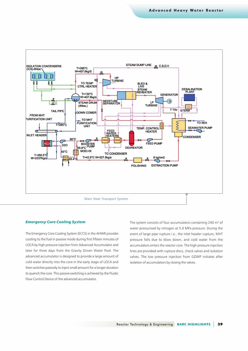
. Main Heat Transport System
The Main Heat Transport (MHT) System of AHWR transports
heat from fuel rods to steam drum. AHWR uses boiling light
water as the coolant in the high-pressure MHT system and heavy
water as the moderator in a low-pressure system. The coolant
recirculation in the primary system is achieved by two-phase
natural circulation, which depends on the density difference
between the hot and cold legs of the primary loop. This mode
of core cooling is adopted not only during normal operation
but also during transients and accidental conditions.
The MHT system consists of a common reactor inlet header
from which 452 inlet feeders branch out to an equal number
of fuel channels in the core. The outlets from the fuel channels
are connected to tail pipes, 113 of which are connected to
each of the four steam drums. From each steam drum, four
down comer pipes are connected to the common inlet header.
During normal operating conditions, the steam drum pressure
is maintained at 7 MPa. The water level in the steam drum at
nominal operating conditions is 2.2 m. The primary loop
circulation rate maintained by the density difference is
approximately 2237 kg/s at nominal operating conditions.
The average core exit quality is about 18.7 % for the rated reactor
operating conditions.
The two-phase mixture leaving the core is separated into steam and
water in the steam drum. The steam-water separation in the AHWR
steam drum is achieved naturally by gravity without the use of
mechanical separators. During hot shut down condition, the decay
heat is removed using main condenser. However, in case of non-
availability of main condenser, Isolation Condensers will remove the
decay heat in passive mode.
Handing over of AHWR Detailed Project Report toDr. Anil Kakodkar, Chairman, AEC by
Mr R.K. Sinha, Director, RD&DG
39 Reactor Technology & Engineering BARC HIGHLIGHTS
A d v a n c e d H e a v y W a t e r R e a c t o r
Emergency Core Cooling System
The Emergency Core Cooling System (ECCS) in the AHWR provides
cooling to the fuel in passive mode during first fifteen minutes of
LOCA by high pressure injection from Advanced Accumulator and
later for three days from the Gravity Driven Water Pool. The
advanced accumulator is designed to provide a large amount of
cold water directly into the core in the early stage of LOCA and
then switches passively to inject small amount for a longer duration
to quench the core. This passive switching is achieved by the Fluidic
Flow Control Device of the advanced accumulator.
The system consists of four accumulators containing 240 m3 of
water pressurised by nitrogen at 5.0 MPa pressure. During the
event of large pipe rupture i.e., the inlet header rupture, MHT
pressure falls due to blow down, and cold water from the
accumulators enters the reactor core. The high pressure injection
lines are provided with rupture discs, check valves and isolation
valves. The low pressure injection from GDWP initiates after
isolation of accumulators by closing the valves.
Main Heat Transport System

40 BARC HIGHLIGHTS Reactor Technology & Engineering
A d v a n c e d H e a v y Wa t e r Re a c t o r
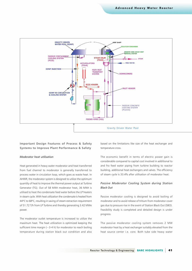
. Gravity Driven Water Pool
The Gravity Driven Water Pool (GDWP) functions as a heat sink
for Passive Concrete Cooling System, condenses the steam
flowing through the isolation condensers during reactor
shutdown and sources low pressure Emergency Core Cooling
(ECC) injection for removing decay heat for three days following
LOCA. The GDWP also functions as a suppression pool to cool
the steam and air mixture during LOCA.
The GDWP is located in the dome region of the reactor building
and contains 6000 m3 of water inventory. Stainless steel lining
of 6 mm thickness is provided inside the GDWP. There are eight
compartments in the GDWP which are interconnected to each
other. Each compartment of GDWP contains one Isolation
Condenser for core decay heat removal during shutdown and
is provided with outlet nozzles at various elevations for flow of
water into the core during LOCA. The Passive Containment
Coolers are located below the GDWP for containment heat
removal during and after LOCA.
The GDWP recirculation and cooling system consists of four
loops. Each loop consists of a heat exchanger, a pump, a filter,
an ion exchanger and a chemical addition tank for maintaining
water chemistry. These loops operate in rotation with two of
them operating at a time. A bypass purification line, consisting
of a filter and an ion exchanger, is provided to remove the
suspended and ionic impurities so as to maintain the crud
concentration within limits.
To prevent biological growth in GDWP, its water will be
continuously recirculated by the re-circulating pumps. The re-
circulation flow will be maintained by two pumps operating at
a time on rotation basis. The GDWP re-circulation system takes
care of re-circulating, filling and draining the water in each
compartment. Each compartment has a separate inlet and
outlet line for supply and drain of pool water respectively.
Emergency Core Cooling System (ECCS)
41 Reactor Technology & Engineering BARC HIGHLIGHTS
A d v a n c e d H e a v y W a t e r R e a c t o r
Important Design Features of Process & Safety
Systems to Improve Plant Performance & Safety
Moderator heat utilisation
Heat generated in heavy water moderator and heat transferred
from fuel channel to moderator is generally transferred to
process water in circulation loop, which goes as waste heat. In
AHWR, the moderator system is designed to utilize the optimum
quantity of heat to improve the thermal power output at Turbine
Generator (TG). Out of 58 MWt moderator heat, 36 MWt is
utilised to heat the condensate feed water before the LP heaters
in steam cycle. With heat utilization the condensate is heated from
44ºC to 68ºC, resulting in saving of steam extraction requirement
of 51.72 T/h from LP Turbine and thereby generating 3.42 MWe
power.
The moderator outlet temperature is increased to utilize the
maximum heat. The heat utilization is optimized keeping the
sufficient time margin (~3-4 h) for moderator to reach boiling
temperature during station black out condition and also
Gravity Driven Water Pool
based on the limitations like size of the heat exchanger and
temperature cross.
The economic benefit in terms of electric power gain is
considerable compared to capital cost involved in additional to
and fro feed water piping from turbine building to reactor
building, additional heat exchangers and valves. The efficiency
of steam cycle is 33.4% after utilisation of moderator heat.
Passive Moderator Cooling System during Station
Black Out
Passive moderator cooling is designed to avoid boiling of
moderator and to avoid release of tritium from moderator cover
gas due to pressure rise in the event of Station Black Out (SBO).
Feasibility study is completed and detailed design is under
progress.
The passive moderator cooling system removes 2 MW
moderator heat by a heat exchanger suitably elevated from the
heat source center i.e. core. Both tube side heavy water

42 BARC HIGHLIGHTS Reactor Technology & Engineering
A d v a n c e d H e a v y Wa t e r Re a c t o r
moderator and shell side Gravity Driven Water Pool (GDWP) water
circulate in the heat exchanger by buoyancy force. GDWP with
6000 m3 water inventory serves as heat sink. Heat exchanger and
the connecting piping are designed to minimise the pressure drop
to achieve the required flow by natural circulation.
During Station Black Out (SBO) condition due to unavailability
of forced circulation & cooling, moderator temperature starts
increasing due to heat generation in moderator and heat
transfer from hot main heat transport system (MHT) at 285°C.
MHT temperature remains hot during station blackout without
any crash cooling provision while Isolation Condensers (ICs)
removing core decay heat by passive valves in operation.
Analytical estimation shows a moderator bulk mean
temperature of 90°C in 1 h 45 min and cover gas pressure
reaches relief valve set pressure of 1.5 kg/cm2 (abs.). The
temperature further rises to 100°C in three hours and continues to
rise with time in the absence of cooling provision. With the passive
cooling provision and 2 MW moderator heat removal, the cover
gas pressure and moderator temperature of the system is maintained
below the relief pressure setting and saturation temperature.
steam pressure. A rupture disc is provided between the passive
valve and the steam drum for releasing the steam to valve by rupture
action at over pressure above the trip set pressures for SDS#1 or
SDS#2.
Passive Moderator Cooling System - Schematic
Passive concrete cooling system
Passive concrete cooling system protects the reactor V1 volume
concrete surface from high temperature MHT, by natural
circulation of water in tubes near the concrete structure.
This passive concrete cooling system has eliminated blowers
and associated power supply failure events. The concrete
temperature is maintained below 55°C by the optimum number of
cooling pipelines, over the conventional cabinet insulation panel
surrounding MHT The natural circulation of water from gravity
driven water pool, in the pipes, maintains the concrete temperature.
Corrugated plate outside the insulation panel gives a better heat
transfer contact with the cooling pipes. Water circulation stabilizes
due to density difference between the cold supply line connecting
GDWP from outside V1 volume and cooling pipes, which picks up
heat transferred through insulation panel.
Passive concrete cooling system design is completed and
experimental facility is being planned to validate the
analytical results.
Schematic flow sheet of Passive Shutdown Device
Passive Shutdown Device
The Passive Shutdown Device (PSD) is an additional provision
to effect shutdown in the event of over pressure in the MHT
system due to the failure of wired mechanical ShutDown System
(SDS-1) and liquid poison injection in moderator (SDS-2) due to any
malefficient activity. PSD adds liquid poison to moderator from a
pressurized poison tank, by actuating a valve passively driven by

43 Reactor Technology & Engineering BARC HIGHLIGHTS
A d v a n c e d H e a v y W a t e r R e a c t o r
Waste heat utilisation from MHT purification circuit to
produce D.M. water
Purification flow is normally cooled in regenerative mode and
later by non-regenerative coolers before passing it to Ion
exchange columns. Non-regenerative cooling is usually provided
at the last stages of cooling which otherwise requires
uneconomical number of regenerative coolers in series with
associated temperature cross in heat exchanger design. In
AHWR, Purification flow 2000 lpm is cooled to 100°C in
regenerative mode and further temperature reduction to 42°C
is achieved in non-regenerative cooler, leading to transfer 8
MWth heat load to process water as waste heat.
Schematic and typical cross sectional views ofPassive Concrete Cooling System
Waste heat utilisation from MHT purification circuitfor desalination - Schematic flow sheet
Time taken by MHT System to Reach 285°C withDifferent Core Power and Different Purification Flow
Sudhir Bhatia <[email protected]>
. Design of Coolant Channel of the Advanced
Heavy Water Reactor
Coolant channel forms the heart of pressure tube type nuclear
reactor. Coolant channel houses the fuel assembly along with
shields and seal plugs. The coolant flows past the fuel assembly
removing the nuclear heat from the fuel pins.
The purification system cooling circuit is modified to utilise the
optimum quantity of waste heat of 5 MWth to produce 300
m3/day Demineralised water by providing an isolation heat
exchanger, which transfers heat from 100°C to 64 °C to Low
Temperature Evaporation (LTE) Desalination Plant. This design
feature lowers the heat load on process water besides producng
300 m3/day D.M. water.
Thermal Analysis for Estimation of Rate of MHT
Temperature Rise
The heating of Main Heat Transport (MHT) system from 35ºC to
285ºC during start up from cold shutdown condition has been
studied by utilising core heat from 2% to 5% Full Power (FP), after
attaining criticality. Analytical estimates shows that the heating time
varies from 5 hrs to 26 hrs for core heat varying from 2% to 5% FP
and purification flow varying from 0 to 100%. These analytical
estimates consider heat capacities of structural, fuel and water
inventory, losses to surrounding moderator, top and bottom end
shield, air surrounding MHT piping in V1 area.

44 BARC HIGHLIGHTS Reactor Technology & Engineering
A d v a n c e d H e a v y Wa t e r Re a c t o r
Coolant Channel Assembly
The AHWR coolant channel has many features which facilitates on-
power fuelling, direct injection of cold water from emergency core
cooling system to hot fuel pins in the event of LOCA, easy
replaceability of pressure tube, suitable interfaces with Main
Heat Transport (MHT) system, as well as annular gap to separate
the hot pressure tube ( 285oC ) from surrounding cold moderator
( 65oC ).
Design Description
Coolant channel consists of cold worked Zr-2.5Nb pressure tube
in the reactor core region, which is extended by stainless steel
end fittings at the top and the bottom. The coolant channel is
located and locked in its position by anti-torque hardware and
yoke assembly attached to top and bottom end fittings
respectively. Bottom end fittings are provided with feeder
couplings to connect it with feeders, which are welded to Inlet
Header. Lower ends of tail pipes are welded to top end fittings
and top ends of tail pipes are connected to steam drum.
Fuel assembly is located inside the pressure tube and is inserted and
taken out of the channel through the top end fitting. The top end
fitting has suitable features to support and locate the fuel assembly
along with the shield plugs in its designed location and to interface
with the fuelling machine to carry out fuelling operations. After
fuelling is over, the top end fitting is closed using a seal plug which
butts against a seal face provided in the bore of the end fitting.

45 Reactor Technology & Engineering BARC HIGHLIGHTS
A d v a n c e d H e a v y W a t e r R e a c t o r
Operational Details
Light water coolant from MHT System enters the coolant channels
through bottom end fittings, which are connected to feeders.
Coolant at 259OC flows past the fuel assembly by removing the
heat generated by nuclear reaction and flows out as steam-water
mixture at 285OC through the tail pipe to the steam drums where
steam is separated and sent to turbine.
Easy Replaceability of Pressure Tube
The estimated life of pressure tube in this reactor is about 30 years
due to various degrading mechanisms such as irradiation creep,
corrosion and hydrogen pick up. Easier replaceability of Pressure
tube is taken into consideration in the design to reduce the duration
of shut down of the reactor, man-rem exposure and the cost of
replacement. Certain features are provided in its design for the
above purpose and are described below.
Pressure tube
Replacement of pressure tube has been planned by removing it
along with bottom end fitting, through the bore of the top end
fitting. This has been achieved by keeping the bore of the top end
fitting more than the maximum outside diameter of pressure tube,
after considering the irradiation induced diametrical creep of 4 %
and the outside diameter of the bottom end fitting. In view of this
and the rolled joint
requirements, pressure tube is
designed to have an out side
diameter of 133 mm and
thickness of 6.1 mm at the top
end and 90 mm outside
diameter at the bottom end.
Rolled Joint
Pressure tube is joined to top end fitting with a rolled joint, which
can be assembled and tested remotely. The rolled joint can be
detached by shock heat method. Top end fitting which is not planned
to be removed during pressure tube replacement, is provided with
an additional set of rolled joint grooves which could be used for
making the second joint.
Pressure tube
Rolled Joint End of Top End Fitting
Feeder Coupling
Feeders are connected to the bottom end fittings by feeder couplings.
This is a special compact mechanical coupling with a self-energising
metal seal as sealing element which requires lower tightening load
than other mechanical couplings. The effectiveness of sealing increases
with pressure in this coupling. The bottom end of the bottom end
fitting is provided with an in-built hub and the feeder is also ending
with a suitable hub. These hubs are provided with a taper on its
outer portion and the inner side of clamp is provided with a matching
taper. When the clamp is tightened over the hubs, they become
closer and the required amount of tightening load is applied on the
sealing element. The feeder coupling has been designed and
developed on the basis of performance tests.

46 BARC HIGHLIGHTS Reactor Technology & Engineering
A d v a n c e d H e a v y Wa t e r Re a c t o r
Composite Sleeve rolled Joint
The tail pipe is of SS304L and is required to be welded to top
end fitting. Hence, it is preferable to have top end fitting of
SS304L in order to avoid a dissimilar metal welding in the nozzle
region. Due to large difference in thermal expansion coefficients
of SS304L and pressure tube material, a rolled joint between
pressure tube and SS304L end fitting operating at high
temperature is not feasible. Hence, a composite sleeve is
designed consisting of outer sleeve of SS403 material which is
having lower thermal expansion coefficient, shrink fitted over
inner sleeve of SS304L material. At higher temperatures, outer
sleeve will introduce compressive stresses on the inner sleeve, which
will partially compensate for the relaxation of contact pressure,
between the pressure tube and the inner sleeve.
Annulus Leak Monitoring System
The Annulus Leak Monitoring System (ALMS) is incorporated in the
design of the coolant channel to ensure ‘Leak Before Break Criterion’.
It is designed to detect leaks from pressure tube, its joints and from
moderator system into the annulus between pressure tube and
Composite Sleeve Rolled Joint
V. Joemon <[email protected]>
. Development of rolled joint detachment
technology
One of the major design features of AHWR is the replaceability
of pressure tube during the lifetime of the reactor. In order to
demonstrate this aspect, a technique for detachment of rolled
joint between end fitting and pressure tube is being pursued.
The technique is based on radio frequency induction heating,
in which the pressure tube in the rolled joint area is rapidly
heated using an induction coil and then suddenly cooled. A
schematic of the technique is shown in the figure. During
heating, as the pressure tube temperature starts increasing and
the stress developed reaches the yield stress, there will be no
further increase of the contact pressure between pressure tube
and end fitting. During subsequent cooling, a gap will be
generated between the end fitting and pressure tube. After
two to four cycles, the joint will become free. During subsequent
heating, an axial load is applied, which will contract the
pressure tube radially and finally it will come out of the rolling
grooves. Variation of contact pressure with temperature
Feeder Coupling
calandria tube sufficiently in advance so that the reactor can be
safely shut down before any catastrophic failure occurs. The annulus
is closed at the top end and open at the bottom.

47 Reactor Technology & Engineering BARC HIGHLIGHTS
A d v a n c e d H e a v y W a t e r R e a c t o r
in the case of 220 MWe PHWR calandria tube rolled joint, as
estimated analytically is given in the Figure.
In order to estimate the various parameters involved and to
optimize their values, a mock up facility is being set up. To
reduce transmission loss, coaxial cable is being purchased, which
Schematic of detachment work.
Variation of radial gap during detachment work
will be used to transfer power from the induction-heating machine
to the work coil. In order to apply axial load during detachment
work, a tool has been designed, as illustrated in figure.
K Madhusoodan <[email protected]>

48 BARC HIGHLIGHTS Reactor Technology & Engineering
A d v a n c e d H e a v y Wa t e r Re a c t o r
. Containment Isolation Devices for Nuclear
Reactors
The peripheral RCC wall of the nuclear reactor is termed as
containment and is the ultimate barrier between the reactor
and the atmosphere. Utilities are fed in and out of the reactor
through pipe penetrations. The largest such penetrations pertain
to ventilation system. The dampers provided for closing these
penetrations and bottling up of the containment are thus critical
equipment of the dynamic containment system. Dampers
provided in such penetrations are required to close in a perfectly
leak-tight manner within few seconds in case of any abnormal
situation. The safety and reliability of entire containment system
depends mainly on these dampers.
Most of the existing systems utilize butterfly valves for this
purpose. These butterfly valves are basically designed for fluid
duty at a system pressure of 5 kg/ cm2 whereas in reactors the
pressure of not more than 2 kg/cm2 is expected even under severe
accidental condition like LOCA. When these valves are used for low
pressure systems handling atmospheric air the performance does
not remain satisfactory. Unequal seal compression, unequal wearing
of seal, different behavior of seal material in water and air, inadequate
deflection and sealing force due to low pressure, accumulation of
dust on sealing surface aggravating the seal compression etc. are
the problems being faced in butterfly valves.
Hence there was a need to design these isolation devices
specifically for the intended application instead of just trying
to adapt available valves in a unsuitable manner. The isolation
devices can be either active type i.e. through external actuation
by means of an electro-pneumatic circuit or passive type i.e.
self-actuating by the fluctuation in system parameters viz.
pressure & velocity of air in the duct during LOCA. Work is
being carried out on both the fronts.
On the active damper side an electro-pneumatically operating,
lightweight, positive seal, airtight damper, with rotary cum axial
motion was developed in TSD. The axial motion provides perfect
sealing by overcoming inherent defects of butterfly valves. This
damper has compressed air to open and spring to close on
active signals. Thus it is termed as active damper. Initial design
utilizes multi-four bar mechanism to achieve the rotary-cum-
axial motion. Efforts are being made to reduce the number of
Pulling tool for detachment work.

49 Reactor Technology & Engineering BARC HIGHLIGHTS
A d v a n c e d H e a v y W a t e r R e a c t o r
linkages. The test results are highly encouraging.
On the passive damper side simple spring loaded disc critically
designed to allow a particular range of flow is being developed.
The disc automatically closes when there are instantaneous
increases in air velocity in the duct.
The active damper along with passive dampers in series can
provide a perfect solution to the need of positive and reliable
isolation of any nuclear reactors. The major works involved are
conception of design, development of prototype working model,
development of testing set up, fabrication and testing prototype
model, test data interpretations and subsequent design
modifications. Presently work is being carried out to design, fabricate
& test a damper suitable for the conditions specified in AHWR
reactors and also to fabricate a damper to establish the design
principles of Passive Dampers.
Various Positions of LinkagesVarious Positions of Linkages

50 BARC HIGHLIGHTS Reactor Technology & Engineering
A d v a n c e d H e a v y Wa t e r Re a c t o r
P. S. Shetty <[email protected]>