Embed Size (px)
Citation preview
1
Date of Issue: November 2014 Affected Publication: API Specification 16F, Specification for Marine Drilling Riser Equipment, First Edition, August 2004
ADDENDUM 2 (includes Addendum 1, issued September 2014)
Page 20, Section 7.6 TENSIONER FOUNDATIONS, replace:
Design loads of all tensioner foundations and all sheave foundations shall be based on the minimum breaking strength of the wire rope, plus the weight of the device and its contents. The foundation shall be designed according to AISC or other nationally or internationally recognized standard. The manufacturer shall provide the mounting and installation information to designer/purchasers, including design load, orientation, alignment, allowable fleet angle, and minimum clearances.
with
The manufacturer shall provide the mounting and installation information to the designer/purchaser, including design load, orientation, alignment, allowable fleet angle, and minimum clearances.
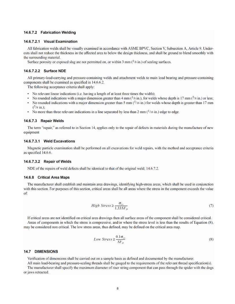
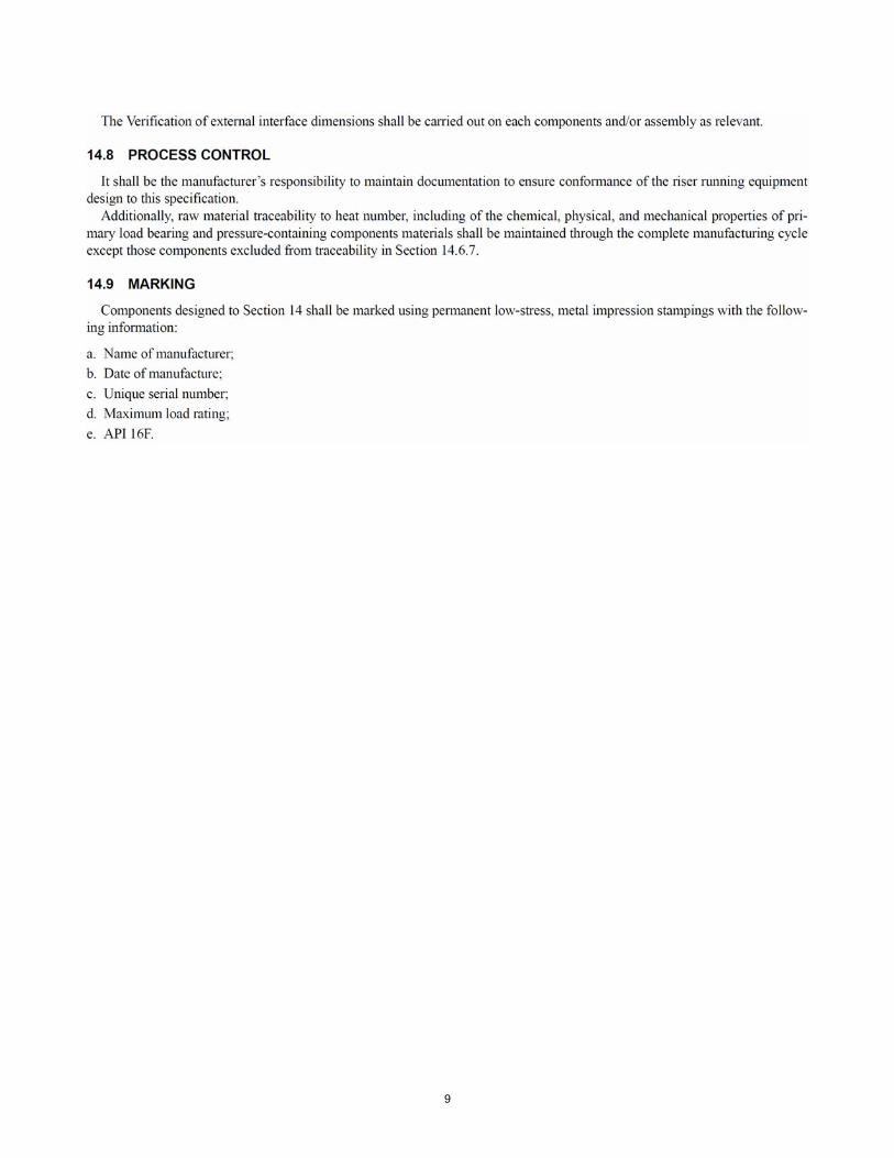
Page 32, Section 14, replace the entire section as follows:
2
3
4
5
6
7
8
9