Embed Size (px)
Citation preview

16/5/2003SCT PAR, Georg Viehhauser 1
Assembly of Modules to Cylinders
Georg Viehhauser

16/5/2003SCT PAR, Georg Viehhauser 2
Assembly at Oxford and KEK• Barrels come to Oxford/KEK from RAL with all the services mounted
and tested.• Modules are only items left to be added at Oxford/KEK to complete
cylinders:– Limited space → high precision during mounting required.– Tasks:
• Mechanical location & fixing of module, • Thermal & mechanical connection to cooling system, • Alignment & connection of dogleg.
• After mounting: performance has to be verified.– Use all final (or very close to it) ATLAS SCT components (power
supplies, off-detector electronics, DCS, cooling).– Compare performance to checks after module assembly.– System studies.
• After passing final acceptance checks: Barrels are shipped to CERN for final 4-barrel assembly.
16/5/2003SCT PAR, Georg Viehhauser 3
Transport
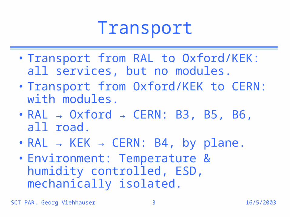
• Transport from RAL to Oxford/KEK: all services, but no modules.
• Transport from Oxford/KEK to CERN: with modules.
• RAL → Oxford → CERN: B3, B5, B6, all road.
• RAL → KEK → CERN: B4, by plane.• Environment: Temperature & humidity
controlled, ESD, mechanically isolated.

16/5/2003SCT PAR, Georg Viehhauser 4
Transport Box
• Two box design• Inner box:
– Al protective frame with conductive plastic panels,
– Central part stays around barrels all time (even during assembly),
– Wrapped air-tight during transport.• Outer box:
– Steel structure and panels, – Handling points for shipping.
• Mechanical coupling through wire rope isolators.
• Plane transports might need different setup.
B3 inner box
Box assembly

16/5/2003SCT PAR, Georg Viehhauser 5
Service Cages
• All services, which will later be fanned out on the thermal enclosure, have to be stored safely for assembly and transport (LMTs, capillaries, readout fibres, DCS sensor wires).
• Storage assembly has to – satisfy ESD and grounding requirements for checks, – provide temporary connections for services during
assembly checks,– clear adjacent barrels for 4-barrel assembly.

16/5/2003SCT PAR, Georg Viehhauser 6
Oxford Assembly Area- Heavy Lab
Cold Room
Control RoomClean
Room Cooling/UPS/Services

16/5/2003SCT PAR, Georg Viehhauser 7
Module Reception - Storage
• ~1500 modules will be shipped from all over the world to Oxford
• Shipping box, which – protects during transport,– provides safe environment for module checks
(thermal and electrical connections, so that module can be checked without opening),
– has mechanical fiducials to align module for module mounting.
• Each module gets tested at Oxford after reception (same tests as at module production site).
• Storage in shipping box in humidity & statically controlled area (up to 400 modules).
• Modules will be kept in shipping box until immediately before mounting.
Module
Connector
Position fiducials

16/5/2003SCT PAR, Georg Viehhauser 8
Barrel Reception
• Barrels will be delivered to tent outside of the heavy lab.• After removal of outer box transfer to lifting cart.• Wheel into clean room, lift to cold room floor level and
move into cold room. • Remove ends of inner transport box, install cable and
fibre supports, connect barrel DCS sensors.• Preassembly checks:
– Verify DCS sensor operation.– Connect cooling system and operate cooling system (cold).
Verify operation.– Confirm harness integrity.

16/5/2003SCT PAR, Georg Viehhauser 9
Assembly Overview
• Tight schedules require parallel operation of 1. and 2. on two assembly stations.
• But: switch between them is complex.→ Do assembly in groups of 96 modules. First 16 rows of
lower modules (16×6 = 96), which then get checked. Then mount upper modules and check them out.
1. Mount modules & make thermal and electrical connections.
2. Verify performance after mounting.3. After completion of barrel: final
acceptance test

16/5/2003SCT PAR, Georg Viehhauser 10
Module Mounting
• High 3d-precision during insertion required → robot.
• Additional operations:1. Align dogleg to pigtail.2. Apply thermal grease on cooling block.3. Mate pigtail and dogleg connector.4. Mount module cooling block clip.Done by hand with tools held by a tooling frame.
Done row-by-row (first lower, than upper):First 1. & 2., then module insertion, then 3. & 4.

16/5/2003SCT PAR, Georg Viehhauser 11
Tooling support and alignment
• Tooling frame with vertical and horizontal travel, attached to front of transport box.
• Positioning of tools by stages, aligned by hand with small lasers.
• Alignment of robot automatically. Survey of brackets on barrel with laser sensors. Coordinates kept in database for retrieval during mounting.
Fine adjustment of tool position
Tooling frame

16/5/2003SCT PAR, Georg Viehhauser 12
Procedure I: Align Dogleg
• Remove tab with circuit board from module box (module stays covered).
• Transfer pigtail connector position to template using position fiducials.
• Position template using alignment rods onto barrel. • Adjust dogleg position (align to module mounting bushes) and fix.
Template
Connector
Position fiducials
Alignment rods

16/5/2003SCT PAR, Georg Viehhauser 13
Procedure II: Apply Thermal Grease
• A rectangular mask covers cooling block (maintains thickness of grease joint).
• Opening of mask just slightly smaller than cooling block surface.
• Back of cooling block supported from tool.
• Grease squeezed out of reservoir by piston lever.
• Applicator moves over mask, scrapes off excess grease.
Piston
Grease reservoir
Mask
Travel

16/5/2003SCT PAR, Georg Viehhauser 14
Done by robot (one program):1. Pick up module from box2. Survey module optically –
verify correct pickup, envelope.
3. Insert module (robot knows where to put it).
4. Drive in screws (limited torque).
Procedure III: Mount Module
Control by touch-screen
Module box

16/5/2003SCT PAR, Georg Viehhauser 15
Procedure IV: Apply Clips
• Same tool used for clip removal.

16/5/2003SCT PAR, Georg Viehhauser 16
Procedure V: Electrical Connection
• Template aligns connectors on pigtail and dogleg.• Pliers force connectors together.• Same template also used for disconnecting.

16/5/2003SCT PAR, Georg Viehhauser 17
Clearances
• Exposed wirebonds on modules demand great care.• All components and module (3-point constrained) must satisfy space envelope
as given in SCT drawings.• Clearances during insertion ~1-2mm on each side (depending on barrel).
Lower module – upper module: ~1.9mm
Component – dogleg: ~1mm
Component – connector: >1.7mm
Hybrid – Optopackage: ~1.2mmIn situ:

16/5/2003SCT PAR, Georg Viehhauser 18
Fault recovery
• Care has been taken to isolate robot from external faults.– Separate UPS.– Compressed air?
• Emergency stop button for operator.• Recovery software will return the module into
box after retracing approach path.• Ongoing task: more failure modes will show
during shake-down before B3 arrival and will be taken care of.
16/5/2003SCT PAR, Georg Viehhauser 19
Dismounting Modules
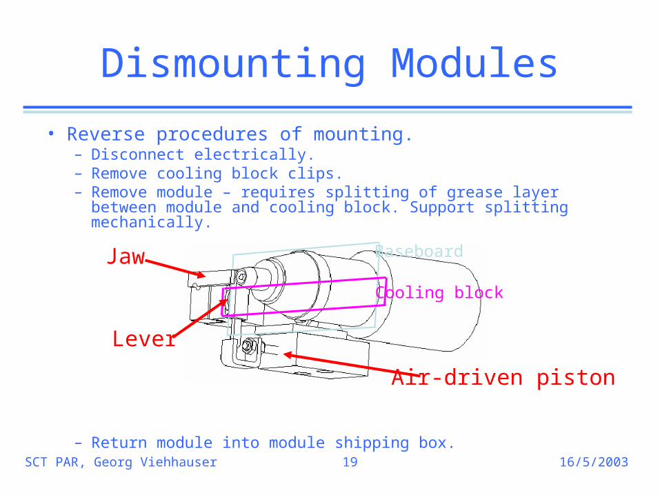
• Reverse procedures of mounting.– Disconnect electrically.– Remove cooling block clips.– Remove module – requires splitting of grease layer between
module and cooling block. Support splitting mechanically.
– Return module into module shipping box.
Jaw
Lever
Air-driven piston
Baseboard
Cooling block

16/5/2003SCT PAR, Georg Viehhauser 20
Time estimates
• Estimated times for assembly:– ~5h for 6 modules (1 row of lower or upper modules) =
~45min/module– 96 modules in 80h = 1 week (5d) of 2 daily shifts (8h) each.
• → During established assembly: mount modules on one barrel for one week, while testing the other, then swap.

16/5/2003SCT PAR, Georg Viehhauser 21
Manpower
• Assembly:– 2 ATLAS assembly techs– Up to 1 tech from electronics workshop– 2 staff from Oxford, 1 staff from UCL.
• Testing: – 1 postdoc and 1 grad student from Oxford.
• Additional manpower from Oxford and other SCT collaborators can be found for limited periods.

16/5/2003SCT PAR, Georg Viehhauser 22
Mechanical QA

16/5/2003SCT PAR, Georg Viehhauser 23
Cooling System
• Evaporative system (cooling capacity ?).
• Drives up to 16 cooling loops (B6 + 2).• Two operation modes:
– C3F8: about -15° (‘cold’) as in ATLAS.– C4F10: about 10° (‘warm’).
• Control as in ATLAS: – Mass flows & pressure drops adjusted
so that cooling power exceeds heat load of detector at any time.
– Heaters after the detector controlled by simple T-feedback so that remaining liquid evaporates.
– No sophisticated control structures, just monitoring (→ DCS).
Compressor
Condensor
Storage
16/5/2003SCT PAR, Georg Viehhauser 24
Electrical QA
• Repeat measurements as at production sites and after reception (allows for direct comparison).

16/5/2003SCT PAR, Georg Viehhauser 25
DCS
• Similar system as in ATLAS• Sensor readout (all SCT barrel
sensors, system status and environment) using ELMBs.
• Control and monitoring of power supplies (14 crates) through ELMB-based crate controllers.
• Distributed PVSS system.• Hardware interlock of cooling loop
temperature through IBOXs, interlock matrix and interlock card in PS crates.
• Additional interlocks for personal safety.
Environment sensors:
ELMBs
IBOXs

16/5/2003SCT PAR, Georg Viehhauser 26
Off-Detector Electronics
• Optical readout (control & data).• One 9U VME crate with VME
CPU, up to 14 RODs and TIM.• One ROD reads 48 modules.• For assembly checks: need 4
RODs. • Only for final acceptance test:
– B3: 8 RODs– B5: 12 RODs– B6: 14 RODs
• Read out histograms from ROD memory for various characterisation checks.
REV C Rod Rev B ROD
TIM
CPUSCTLV2 PS

16/5/2003SCT PAR, Georg Viehhauser 27
Power supplies
• Supply HV and LV.• Crate holds also controller
(ELMB-based, connected through CAN bus to DCS) and interlock card.
• One crate supplies 48 modules.
• Assembly checks need 2(4) crates.
• Final acceptance tests need 8 (B3), 12 (B5) and 14 (B6) crates.
Interlock card Controller
LV cards HV cards

16/5/2003SCT PAR, Georg Viehhauser 28
Power, ESD and Grounding
• Power to critical components (power supplies etc.) backed up by UPS.
• Special care has been taken to provide clean ground to allow meaningful electrical checks of assembled barrels.
• All items in the cold room conductive and grounded, standard ESD procedures followed.

16/5/2003SCT PAR, Georg Viehhauser 29
Status I
• Transport infrastructure:– B3 inner transport box complete and at RAL. Outer box needs
finishing design and construction. – B3 service cages: mechanical parts are ready. Mock assembly
under way. Electrical components to be delivered soon.
• Heavy Lab infrastructure:– Clean room ready, used for power supply tests. Ready to
receive and store modules.– Still to be done: reception tools (lifting cart etc.)– Cold room: service supports being installed. After that: clean &
close. – Power cables: ordered. To be delivered in May.– Readout fibres: ordered. To be delivered in May. – Cooling system: Pipework being installed.

16/5/2003SCT PAR, Georg Viehhauser 30
Status II
• Tooling:– Most tools have been built and are being tested in the cold room.– Robot: routinely mounting modules. Now programming recovery
procedures. – Wait for sector prototype to practise procedures in realistic
environment.
• Read out and power supplies:– Power supplies: 1 crate with cards in Oxford, ironing out
problems with ELMB crate controller.– DCS: Environment monitoring operating, working on power
supply control and monitoring.– Off-detector electronics: crate with CPU, TIME and 2 RODs in
Oxford. Reads out optically one module on bench (SCTLV2 power supplies). Standard checks working.

16/5/2003SCT PAR, Georg Viehhauser 31
Schedule
• Until arrival of B3 (expect end of June):– Finish all remaining transport infrastructure. – Finish all the remaining tasks to build infrastructure
(cooling system, cables, cold room, etc.). – Test mounting procedures with sector prototype.
Shake down procedures. Train technicians.– Get power supplies with control software and off-
detector electronics with DAQ software working.– Start receiving modules.
• After B3 arrival:– Barrel reception checks.– Start mounting (production ramps up from 6
modules /wk to 96 modules/wk)