Embed Size (px)
Citation preview

ENGINEERING CHANGE NOTICE Pa@ 1 Of 2
1.~~~644049 ..... ...... ... . . . . ........ . . . . . . . . . . . . h i . ECN
I. ECN Category (mark one)
Direct Revision @ 0 Change ECN
0 Temporary Standby Supersedure 0 CancsWoid 0
Supplemental 0
3s. Deauiptlon of Change rhis ECN revises "Design Package Test Weights for Fuel Retrieval System" HNF-4460 from rev 0 :o rev 1 and adds the following information:
1)verification results from testing !)test/calabration test specification and data sheets in Appendix B
13b. Design Beseline Document7 @ Ye8 0 No
3. Orbhatots Name. Organlzstion. MSIN, and Telephone No. 4. USQRequlmd 5. Date David Tedeschi E6-15, 372-1485 @Yea HN#SepteInber WI 10, 1999
8. Prcjed T"o.Mlork Order No. Fuel Retieval System /SNF
9. Dowment Numben Changed by this ECN (Includes
HNF-4460 rev 0 N/A N/A
7. Bldg.lSys.Fsc. No. 8. Approval Designator
105 KE 105 KW Q 10. Related ECN No@). 11. Related PO No.
sheet no. and rev.)
954 : K - 99 - I 2 O L
Criteria Change
Environmental FadlHy DeaCUvaUon 0 As-Found Fadlltate Const.
7RS Working Files X3-88 1 3 . M . Koons X3-88 1 1.R. Jackson K5-22 1 r . 1 Dielh x3-80 1
4-7900-013-2 (10197) A-7900.013 1
~
28. Modkatlon Work 0 Ye8 (RII out Elk. 12b) 0 No NA Blks. lZb,
{Zc. 1Zd)
1Zd. Restored to lnil Condition (Temp. or Standby Eods only)
12b. Work Package No. 1Zc. Mcdiication Work Completed
N/A N I A N/ A Desbn Authoritylc Engineer Signature 6 Design AuthorityKc&Erqlnr Signature (L
??ate te

Page2of 2 ENGINEERING CHANGE NOTICE
8. Des@ Verification 17. Cost Impact ENGINEERING CONSTRUCTION Required
0 Yes I Additional 0 t N/A Additional 0 $ N/A I Improvement 0 N/A
1. ECN (use no. from p ~ . 1)
6 4 4 0 4 9
18. Schedule Impact (days)
@ No I Savings 0 s N/A Savings 0 $ N/A
- SDDDD 0 Functional Design Criteria 0 Operating Spechlcation 0 Criticality SpecMcatiin 0 Conceptual Design Report 0 Equipment Spec. 0 Const. Spec. 0 Procurement Spec. 0 Vendor Information 0 OM Manual 0 F M S A R 0 Safety Equipment List 0 Radiation Work Permit 0 Environmental Impact Statement 0 Environmental Report 0
Delay 0 N/A
SeismldStress Analysis 0 StresrlDesign Report 0 Interface Control Drawing 0 Calibration Procedure 0 Installation Procedure 0 Maintenanca Procedure 0 Engineering Procedure 0 Operating Instruction 0 Operating Procedure 0
IEFD Drawing 0 Cell Arrangement Drawing 0
Fac. Proc. Samp. Schedule 0 Inspection Plan 0
Operational Safety Requlrement 0
Essential Material Spedfication 0
Tank Calibration Manual 0 Health Physics Procedure 0 Spares Multiple Unit Listing 0
Component Index 0 ASME Coded Item 0
Computer Software 0 Ebctrlc Circuit Schedule 0 ICRS Procedure 0
Process Flow Chart 0 Purchase Requisition 0 Tickler Fib 0 None E4
Test ProcedureslSpecMcation 0
Human Fador Consaeration 0
Process Control ManuaVPlan 0
Environmental Permit 0 Inventory Adjustment ~equest 0 0 0. Other Affided Documants: (NOTE: Documents listed below will not be revised by this ECN.) Signatures below indicate that the signing
organization has been notified of other afficted documents listed below. Dowment NumberRevlsion Document NumberRevision Document NumberRevisiin
None
1. Approvals Signature Date
Design Authority 0 . D. Groth
Cog. Eng.
Cog. Mgr.
lo17191
QA J.I . Diehl X3-80
Safety
Environ.
Other
PE ”.
QA Y
Safety
Deslgn
Environ.
Other - Signature or a Control Number that tracks the Approval Signature
ADDlTlONAL
A-7900-013-3 (10197;

a HNF-4460, Rev. 1
Design Package Test Weights For Fuel Retrieval System (OCRWM)
David Tedeschl for Duke Engineering and Services Hanford, Richland, WA 99352 US. Department of Energy Contract DE-AC06-96RLl3200
EDT/ECN:=j., 6+'16Y9 UC: 2050 105363 G A 3 0 Org Code: 21371 Charge Code: CACN: %54% C O A : M / / M F s Q 0 J l B&R Code: EW 7040000 Total Pages: 71 r- F
Key Words: Spent Nuclear Fuel, Fuel Retrieval System, Weights, Test
Abstract: This is a design package that documents the development of test weights used in the Spent Nuclear Fuels subproject Fuel Retrieval System.
TRADEMARK DISCLAIMER. Reference herein to any m c commercial prcduct, procass, or service by trade name, trademark, manufacturer, or otherwise, does not necessarily constitute or imply its endorsement, recommendation, or favoring by the United S$$s Government or any agency thereof or its oon~actm or subcontmton.
Printed in the United States of America. To obtain wpies of this document, mntaet: Document Contml Services, P.O. Box 954, Mailstop H6-08, Richland WA 99352, Phone (509) 372-2420; Fax (509) 376-4989.
/Q-a6-9? Dale Release Stamp
Approved for Public Release A-€400473 (01197) GEF321

Design Package Test Weights for Fuel Retrieval System
A-7320-005 (10/97)

Design Package
Test Weights for Fuel Retrieval System (OCRWM) HNF-4460, Rev 1
August 25,1999
By H L. Roach . Of
F1 uorDaniel Northwest 1200 Jadwin
Richland, WA 99352
For Bruce Groth Reuresenting 2 P.O. Box 350
Richland, WA 99352

Fuel Retrieval System Small Tools Design Package Test Weights
HNF-4460, Rev 1 August 25,1999
1.0 Introduction Page 2
The K Basins Spent Nuclear Fuel (SNF) project consists of the safe retrieval, preparation, and repackaging of the spent fuel stored at the K East (KE) and K West (KW) Basins for interim safe storage in the Canister Storage Building (CSB).
Multi-Canister Overpack (MCO) scrap baskets and fuel baskets will be loaded and weighed under water. The equipment used to weigh the loaded fuel baskets requires daily calibration checks, using test weights traceable to National Institute of Standards Testing (NIST) standards. The test weights have been designated as OCRWM related in accordance with HNF-SD-SNF-RF'T-007 (McCormack).
2.0 Scope
2.1 Objectives
The scope of this design package is to document the design and fabrication of two NIST traceable test weights to be used for the daily calibration of the load measuring equipment on the monorail mounted MCO StiMback grapple.
2.2 Products Delivered
This package will deliver the following:
Documents
a) This document, which includes product requirements, design analysis, graphical depictions, and calibrations reports.
b) Hanford formatted detail and assembly drawings.
Hardware
a) NIST traceable test weight. Dry weight will be 1560.4 kg (- 3437 Ibs.). Underwater weight will be 1362 kg (-3000 Ibs.). Weight will be fabricated to +/- 0.5 % of the underwater weight.
b) NIST traceable test weight. Dry weight will be 654 kg (- 1440 Ibs.). Underwater weight will be 570 kg (-1256 Ibs.). Weight will be fabricated to +/- 0.5 % of the underwater weight.
c) Lifting beam to place the test weights in their storage locations at K Basins using a standard 1 ton chain fall or hoist with standard hook.

Fuel Retrieval System Small Tools Design Package Test Weights
HNF-4460, Rev 1 August 25,1999
3.0 Products Requirements and Constraints Page 3
The general design requirementskriteria for the Spent Nuclear Fuel Project Fuel Retrieval subproject is in HNF-S-0461, p. The following are additional requirements:
3.1 DimensionaWhysical Constraints
a) Diameter of test weights will be 22.25 +/- .010 inches.
b) Maximum height shall be less than 33.75 inches (See figure 1).
c) No part of the test weights may weigh more than 771.8 kg (1700 Ibs.). (HNF-2229, Appendix J).
d) Weights must fit storage locations along monorail no. 27 on the Process Support Table, BNFL drawing DW-327, rev. 6.
3.2 Material Requirements
K Basins Design Guidelines (Roe 1995) shall be used as the source document for establishing material design requirements. Material requirements that pertain to the test weight construction are as follows:
Carbon steel is an acceptable material for K Basin equipment. Carbon steel, if used, shall be coated to prevent corrosion andor ease decontamination. Coating shall consist of a general AmercoatlM epoxy system consisting of AmercoatTM Number 64 primer and AmercoatTM Number 66 seal gloss topcoat.'
300 Series Stainless Steel (SST) is an acceptable material. 300 Series SST shall be used for lifting beams andor strongbacks.
If lead is used it will be encapsulated to prevent contamination of the lead.
3.3 Environmental Constraints
a) Test weight material must be able to withstand the effects of high radiation field of 40 rem I hr.
I AmercoatTU is a registered trademark of Ameron protective Coatings Group, Brea Calif.

Fuel Retrieval System Small Tools Design Package Test Weights
HNF-4460, Rev 1 August 25, 1999 Page 4
b) Test weight design shall accommodate 46-53 OF basin water temperatures.
c) Test weight materials shall be compatible with the deionizeddemineralized water.
3.4 Operational Requirements
a) Test weights will be designed for low corrosion during continuous underwater storage at K-Basin.
b) The weight accuracy tolerance will not be exceeded from corrosion of the test weights over the design life of the test weights.
c) Weights will be lowered into the K-Basin, moved and placed in their storage location using a monorail hoist system with a standard 1 ton chain fall or hoist with a standard hook.
d) Weights must interface with the fuel basket grapple, H-1-82864, rev. 0, sheets 1 and 2, and BNFL drawing DW-209. Fuel basket grapple will be used to lift test weight during load cell calibration.
e) Specified test weight, 1362 kg (3000 Ib.) and 570 kg (1256 Ib.) shall be as measured under water. Fabrication shall be to +/- 0.5% of the specified weight. Design shall take into account the buoyant effect of displaced water.
r) Design life shall be 10 years. Frequency of use will be daily.
3.5 Equipment Marking Requirements
a) Below the hook lifting devices used with the test weights shall be marked as follows:
The number(s) of the H-1 drawing used for the equipment design and construction.
Weight (If over 100 Ibs.)
Rated load.

Fuel Retrieval System Small Tools Design Package Test Weights
HNF-4460, Rev I August 25,1999 Page 5
% r - ~. .
1
T- ' I.
d
1
6
5
r

Fuel Retrieval System Small Tools Design Package Test Weights
HNF-4460. Rev 1
3.6
3.7
3.8
3.9
3.10
August 25, 1999 Page 6
Calibration Requirements
a) Weights shall be certified for underwater weight using a source traceable to NIST standards.
b) Test weights shall be certified to +/- 0.5% of its rated underwater weight.
Design Stress Criteria
a) Test weights shall be designed with a design factor of 3.0 based on the yield stress of the material.
b) Below the hook lifting devices will be designed in accordance ANSI B30.20, Below the Hook Lifting Devices.
Welding Requirements
All welding shall be in accordance with ANSVAWS D1 .l , Structural Welding code.
Maintenance Requirements
Equipment shall be designed for no maintenance.
Applicable Laws, Regulations, and Standards
The applicable Fluor Daniel Hanford Engineering procedures for documenting design, review, and approval of engineering documents shall be used.
4.0 Development of Product
4.1 Management of Task
4.1.1 Engineering
Engineering design, design analysis, and preparation of Hanford formatted H-1 drawings will be done by Fluor Daniel Northwest (FDNW). Documents will be reviewed and approved by Duke Engineering & Services Hanford.

Fuel Retrieval System Small Tools Design Package Test Weights
HNF-4460, Rev 1 August 25, 1999
4.1.2 Fabrication I Calibration Page I
FDNW will be responsible for fabrication of the test weights and supporting equipment. In addition FDNW will be responsible for initial certification of the test weights.
4.2 Development
4.2.1 Conceptual Design
The conceptual design for the two test weight assemblies are shown in Appendix A of the calculation and is listed as Figures Al, and A2.
The 1362-kg (3000 Ib. measured underwater) test weight assembly is showed in Appendix A, Figure Al . It is fabricated entirely of 304 SST. It is necessary to fabricate this weight in three pieces to meet the requirement that no part of the test weight can weigh more than 1700 Ibs. (in air). Size, shape, dry and underwater weight, and surface areas are shown. It is anticipated that the test weight can be fabricated from thick plate or solid billet (if available).
The 570-kg (1256 Ib. measured underwater) test weight assembly is showed in Appendix A, Figure A2. It is also fabricated entirely of 304 SST. Size and shape, dry and underwater weight, and surface areas are shown. Method of fabrication will be the same as for the other test weight.
The Lifting beam is used to lower the test weight sections into the K-Basin using a standard 1 ton crane or chain hoist and is shown in Appendix A, Figure A3. The largest weight that will be lifted using this lifting beam is 1700 Ibs. It was designed for a 1800 Ib maximum load to give it a capacity slightly larger than what is required. It is constructed entirely of 304 SST as required by the K Basin design guidelines (Roe 1995).
4.2.2 Final Design
The final design was documented on a drawing titled “FRS In-Pool Equipment Test Weights” and its number is H-1-83994. It was fabricated in the DYN C o p (Hanford site fabrication shops) under work package number 2H9903763. It was tested and certified at the Numatec operated 305 test facility.

Fuel Retrieval System Small Tools Design Package Test Weights
HNF-4460, Rev 1 August 25, 1999 Page 8
Of significant note is that the third piece of the 3000 Ib. weight was removed from the design in order to improve ease of installation. This resulted in a calibrated weight of 2954 Ibs. in water. This is acceptable as long as it is certified to within k 0.5% of actual weight.
4.3 Verification of Product Design
The test weights were verified through testing and calculations. Calculations were used to verify those items, which could not be reasonably tested. The calculations focused on the environmental issues such as corrosion. The testing verified that the design weight was met in and out of water. The test verification produced a documented certified calibration for each piece if the weight.
4.3.1 Design Calculations
Design calculations are included in Appendix A. The following calculations were made:
Calculations were made to evaluate the impact of corrosion of the test weight during the IO-year design life of the test weights on the accuracy of the test weights. The calculations showed that the corrosion of the test weights over a 10-year design life resulted in a 0.08 % (max) decrease in the weight of the test weight. This will not impact the required accuracy of the test weights (see Appendix A, 2.6). If the test weights are re-calibrated during the 10 year period corrosion will be even more insignificant since re- calibration will account for material loss since the last calibration.
Likewise the variation of the basin water temperature proved to have a very small impact on the measured weight of the test weights. Temperature variations will result in a 0.008% variation in measured weight. The calculation made is in Appendix A, 2.6, and shows that basin water temperature can be ignored.
Evaluation of corrosion on accuracy of test weights
Evaluation of basin water temperature on test weight accuracy
Evaluation of material and weld stresses

Fuel Retrieval System Small Tools Design Package Test Weights
HNF-4460. Rev 1 _ _ August 25; 1999 Page 9
4.3.2 Testing/Calibration
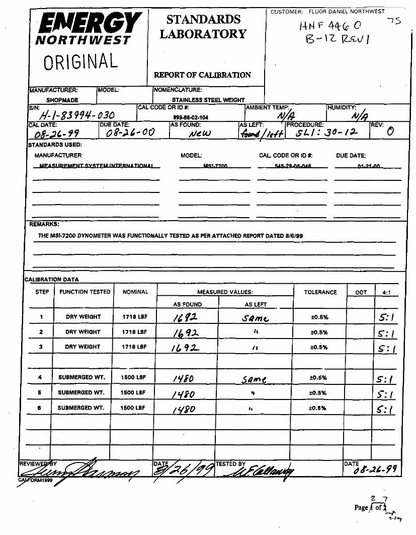
Testingkalibration was performed by Energy Northwest Standards Laboratory. A Fluor Daniel Northwest (FDNW) Design engineer provided a statement of work which provide the testing steps that they needed to perform. The FDNW engineer observed all the steps in the performance of the calibration. The statement of work along with the data sheet is in Appendix B.
The weights were weighed three times with a calibrated dynamometer in dry air and in the water and an average weight was calculated. The calibration data for the dynamometer is in Appendix B. The average weight for each of the weights did not deviate at all. For instance, if 1436 Ibf was measured, then the next two measurements showed the same value. All the measurements showed the weights were in tolerance too. See Table 1 for test data. The actual data sheets are listed in Appendix B. Final test data is as follows:
4.4
* Weights shown are the average weight.
Conclusion
The test weights were designed as specified by the requirements and are documented on the drawing numbered H-1-83994. The weights have been calibrated and verified to meet the designed weight within tolerance. The Energy Northwest calibration recall numbers are 999-86-02-103,999-86- 02-104. and 999-86-02-105.

Fuel Retrieval System Small Tools Design Package Test Weights
HNF-4460, Rev 1 August 25, 1999
5.0 References Page 10
AWS, 1996, Structural Welding Code, AWS D1.1, D1.2, D1.3, American Welding Society, Miami, Florida
ANSI, 1985, Below the HookLifting Devices, ANSI B30.20-85, American National Standards Institute, New York, NY
Drawing, K-Basin SNF Storage Basket Mark IA, H-2-828060, Rev 1, Duke Engineering & Services Hanford, Richland Washington
Drawing, Fuel Basket Grapple End Effector Assembly, H-1-82864, Rev 0, MCE Engineering, Richland Washington
Drawing, FRS In-Pool Equipment Process Table Supports Arrangement, DW-327, Rev 6, British Nuclear Fuels Ltd., Richland, WA
Duncan, D.R., 1998, Submerged Weight of Scrap Baskets Issue Closure Package, HNF-3058, Rev. 0, Duke Engineering & Services Hanford, Richland Washington
Henderson, J.M., 1998, Fuel Retrieval Sub Project Project Analysis Report for Safety Class in Pool Equipment, HNF-2229, Rev 0, British Nuclear Fuels Ltd., Richland, WA
Groth, B.D., 1998, Specification for Design of the SNF Project Fuel Retrieval Subproject, HNF-S-0461, Rev. 1, Duke Engineering & Services Hanford, Richland, Washington
Roe, N.R., 1995, K Basins Design Guidelines, WHC-SD-SNF-DGS-001, rev. 0, Westinghouse Hanford Company, Richland, Washington
McCormack, R.L., 1999, HNF-SD-SNF-RF'T-007, Application of the Office of Civilian Radioactive Waste Management QA Requirements to the Hanford Spent Nuclear Fuel Project, Duke Engineering and Services Hanford, Richland, Washington

Fuel Retrieval System Small Tools Design Package Test Weights
HNF-4460, Rev 1 August 25,1999 Page A-0
Appendix A
Design Calculations

HNF-4460 Rev 1 Page A-1
The following analyses are verifications for the design of the test weights for the Fuel Retrieval System.

FLUOR DANIEL NORTHWEST, INC. HNF-4460, 1 & CALCULATIONS AND SKETCHES SHEET
DEPARTMENT: Mechanisms ORIGINATED BY: Engineering
ENG COMM NO: CHECKED BY:
AREA: 100 K REVISED BY
SUBJECT: Test Weights for K-Bash
Client: Duke Engineering 8 Services Company Hanford
Task Order Number: 65100331 2F04
Deslan Calculations for K-Basin Test Weiahts
ORIGINATED BY: H.L. Roach
CHECKED BY: R.G. Holienbeck

-- FLUOR DANIEL NORTHWEST, INC. HNF-4460, wv I
CALCULATIONS AND SKETCHES SHEET
DEPARTMENT: Mechanisms ORlGiNATED BY: Engineering
ENG COMM NO: CHECKED BY:
AREA: 100 K REVISED BY:
SUBJECT: Test Weights for K-Basin
1.0
The purpose of these calculations is to calculate the following for the Fuel Retrieval System test weights.
rn Conceptual design of 304 Stainless Steel (SST) 3000 Ib. test weight. Calculate dry weight, underwater weight, and surface areas.
rn Conceptual design of 304 SST 1256 Ib. (570 kg). test weight. Calculate dry weight, underwater weight, and surface areas.
Conceptual design of lifting beam for test weights.
Evaluate effect of corrosion on accuracy of test weights
rn Evaluate effect of basin water temperature on accuracy of test weights.
Evaluate material and weld stresses for conceptual Design.
2.0 2 2.1 Conceptual Design and Physical Properties of 3000 LB Test Weight
Figure A I shows the proposed conceptual design for a 3000-LB test Weight. The following summarizes the physical properties of this design:
rn All stainless steel construction rn Three part design
No part weighs over 1700 LBS. Overall height is 32.62"
rn Diameter is 22.25" rn Combined underwater weight is - 3000 Ibs. rn Total exposed surface areas is - 4912.2 in2. rn Volume is - 12042 in3

FLUOR DANIEL NORTHWEST, INC. HNF-4460, Rev 1
CALCULATIONS AND SKETCHES SHEET
Mechanisms DATE: 5r/16/94 DEPARTMENT: Engineering
ENG COMM N O CHECKED BY: DATE:
AREA: 100 K REVISED BY:
SUBJECT: Test Welghts for K-Basfn
. DATE: v-4
C4-l m-
I r n m
.-- .
Page A4

FLUOR DANIEL NORTHWEST, INC. HNF-4460, -1 CALCULATIONS AND SKETCHES SHEET
DATE: 5/24 /G9 5 / z 4
DEPARTMENT Mechanlsrns Engineering
ENG COMM NO: CHECKED BY: DATE:
AREA: 100 K REVISED BY: DATE:
SUBJECT: Test Welghts for K-Basin
Helgm 18 11.875”
Body Displaced Water
Check WelgM Change per inch ,
Need to add: New Height
Check New Height
1nA3 1nA3 Maln Plate
4485.047 0.000 4510.265
408.508 Ib Under 109.236 lbAn
3.740 in 15.615 In
15.615 in
lnA3 lnA3 Maln Plate
1nA3 lnA3 Lugs Total Wt Ibs
1 1.41 8 4496.465 1281.492 11.418 4521.883 -162.781
Totala 1281.492 Dry Total-> 1118.712 Wet
lnA3 1nA3 Lugs Total Wt Ibs
.. .

FLUOR DANIEL NORTHWEST, INC. HNF-4460, *V 1
CALCULATIONS AND SKETCHES SHEET
DEPARTMENT:
SUBJECT: Test Weghts for K-Basin
11.418 5921.979 11.418 5947.197
Total -> 1473.665
Check New Helght
11.418 5922.022 11.418 5922.022
Total -> 1687.776
Total First Two Parts 2948.248 Ibs (Wet) 3000.000 Ibs (Wet) 61.762 Ibs (Wet) 0.576 inches - Estimate
Height is 0.676 In
lnA3 lnA3 lnA3 1nA3 Maln Plate Lugs Total Wt Ibs
6481.881 0.000 11.418 6473.299 1844.890 6461.881 11.418 6473.299 -233.039
Total-> 1844.890 Dry Total -> 1611.851 Wet
1690.000 Ib (dry) 154.890 Ib Over 102.756 lbnn
-1.507 In 18.493 In
16.493 In
__.-- . . Page A6

FLUOR DANIEL NORTHWEST, INC.
CALCULATIONS AND SKETCHES SHEET
HNF-4460, Rev 1
DEPARTMENT: Mechanisms DATE: 6/ZO& Engineering
ENG COMM NO: DATE:
AREA io0 K REVISED BY: DATE: ?+-0/99
; UBJECT:
issaced Water 207.675 0.000 207.675 -7.476 '
Total -> 59.187 Dry Total -> 51.711 Wet
Tarqet Weight 51.762 ib(Wet) . -ck Weight -0.041 Ib aiculate W n 89.776 lbnn
dd additional height 0.000 In ew Helaht 0.576 In
I
t welght iht 2999.959 Ibs
-- - . . . Page A7

FLUOR DANIEL NORTHWEST, INC. HNF-4460, piet I CALCULATIONSANDSKETCHESSHEET
DEPARTMENT:
ENG COMM NO: DATE:
DATE
SUBJECT: Test Weights for K-Basin
2.2 Conceptual Design and Physical Properties of 1256 Ib. (570 kg) Test Weight
Figure A2 shows the proposed conceptual design for a 1256 Ib. (570 kg) test Weight. The following summarizes the physical properties of this design:
All stainless steel construction One piece design Test weight weighs 1439.8 LBS in air. Overall height is 26.19” Diameter is 22.25” Combined underwater weight is - 570 kg 1256 Ibs.). Total exposed surface areas is 1861.64 in Volume is - 5044.43 in3
1

- FLUOR DANIEL NORTHWEST, INC. HNF-4460. b1
CALCULATIONS AND SKETCHES SHEET
DEPARTMENT: Mechanisms DATE: 9/26/Gf)
s/‘Lo/s9 Engineering
ENG COMM NO: DATE:
AREA: 100 K DATE:
SUBJECT: lest Welghts for K-Basin
- DRY WIGHT: 1459.72 LBS UNDERWAER WRMT: 125&62 LBS SURFACE AREA - 1861.64 IN”2
.. Page A9

FLUOR DANIEL NORTHWEST, INC. HNF-4460. *'I CALCULATIONS AND SKETCHES SHEET
Engineering DEPARTMENT: Mechanisms DATE: GfZd/fi ENG COMM NO: DATE:
AREA: 100 K RNISED BY: DATE
SUBJECT: Test Weights for K-Basin

FLUOR DANIEL NORTHWEST, INC. HNF-4460,1 Rev 1
CALCULATIONS AND SKETCHES SHEET
DEPARTMENT: Mechanisms Engineering
ENO COMM NO: DATE: AREA: 100 K REVISED B Y DATE: 5/.../44
i .
SUBJECT: Test Welghts for K-Basin
11.418 5000.865 Total-> 1418.059 Dry Total -> 1238.028 Wet
18.612 lUh&
95.453 lbAn 119.316 Ib e- OK
Check New Helght of 13.306"
Steel Shell with cutout 5033.577 11.418 5070.213
Total-> 1437.824 Dry Total -> 1255.296 Wet
0.211 Ibpnder <-OK
95.401 lbAn 17.268 Ib <- OK
Helght of 13.306 is OK1
- - ., .. .... --
. PageAll''.+ . _

FLUOR DANIEL NORTHWEST, INC. HNF-4460, I Rev 1 CALCULATIONS AND SKETCHES SHEET
DEPARTMENT: Mechanisms Engineering
ENG COMM NO: DATE:
AREA: 100 K DATE * a 4
SUBJECT Test Weights for K-Basin
2.3 Conceptual Design and Physical Properties of Lifting Beam for Test . Weights
Figure A3 shows a conceptual design for a liiing beam designed to allow the test weight sections to be lowered into the K-basin.
Construction is all 304 Stainless Steel. Load capacity is 1800 Ibs.
Page A12

FLUOR DANIEL NORTHWEST, INC. HNF-4460, Rev 1 ._ - - --
CALCULATIONS AND SKETCHES SHEET
DEPARTMENT: Mechanisms Engineering
ENG COMM NO: AREA: 100 K DATE: 4
-0.50
FIGURE A3 - TFST WIGHT SPRFADFR BFAM
1800 LB LOAD CAPACITY ALL 304 STAINLESS STEEL
4 (1.00) -
0.44 R
.- .. .-
Page A13 1.50

FLUOR DANIEL NORTHWEST, INC. " F - 4 4 6 0 , Rev 1
CALCULATIONS AND SKETCHES SHEET
DEPARTMENT: Mechanisms Engineering
ENG COMM NO: AREA: 100 K
SUBJECT: Test Weights for K-Basin
. . : I
* . : , . : .... .. . . . . . . . . . . . . . . , . . . - _._.
. . . . . . . . . . . . . .
.. .- ....- .2 .-.a- L
. . . . . . . . I
I- n
--i------
Page A14

FLUOR DANIEL NORTHWEST, INC. m-4460, Rev 1 CALCULATIONS AND SKETCHES SHEET
Engineering DATE qlia l 5 5 DEPARTMENT: Mechanisms ORIGINATED BY:
ENG COMM NO: DATE
DATE: P 5 /ze/q
SUBJECT: Test Welghts for K-Bash
. . ..:- . - I - . . .-
. . . . . . . .- 1 :

~ - __
FLUOR DANIEL NORTHWEST, INC.
CALCULATIONS AND SKETCHES SHEET
DEPARTMENT Mechanisms DATE: 6 / 9 h ENG COMM NO: DATE:
DATE:
SUBJECT Test Weights for K-Basin
. . . I
. . . . . . . .
2 . . !.. __ [Reference: Republic Steel Corporation, 1976, Mean Coefficient @ 32-212Oqe ' .
-. . . . . . . . . .
= ;036 'bAf13 Page A16 ...

FLUOR DANIEL NORTHWEST, INC. . "F-4460, 1 Rev 1 CALCULATIONS AND SKETCHES SHEET
DEPARTMENT: Mechanisms DATE: 5fU/f5 ENG COMM NO:- DATE:
AREA: I00 K REVISED BY: DATE:
Engineering
i --: - Test Welghts for K-Basin L -
. . SUBJECT: * ! , ! : ' . : . . j .i . . - I . !-..:. !.-+.!..-A- .. -.--+-,
. . . . . . . . . . . . . . . . . . . . ... I . . _ ..... -. :. . . . ; : . . : . . r ... ! :+-. . . . . : . .
i . .
.. .............. . . . . . . . . .
~ ....... ;... .:" i . ._I .......... - ..... , . _. . . . .,.. I . :
....... . . ._ --.- i.---:--:..- '2- ._ -..; - . . , I
.......
Page A17 '.


I , >
FLUOR DANIEL NORTHWEST, INC.

FLUOR DANIEL NORTHWEST, INC. HNF-4460 Rev. I
CALCULATIONS AND SKETCHES SHEET
DEPARTMENT: Mechanisms ORIGINATED B Y
ENG COMM NO: CHECKED BY: DATE:
AREA: 100 K RWISED BY: DATE
SUBJECT: Test Welghts for K-Basin
Engineering
t//7 &c
: I I i> , , . : , . ; -' ...(... - . - : _ I
. . . . . . . . . . . . . .... ... . . . . . . .- . , I 1 :
: . . # . A I
. . . . . . . ........ . .
. . . . . . . . . . _.
. , .. ._ .. . . . . . . . . . . . . : . ,..< .., . ' - _ _ . . . - . . , .
.. . . . . . . . . . . . ... i j
...... . . . . . . . . . . . . . . . . . . . . . . .
Page A20

FLUOR DANIEL NORTHWEST, INC. HNF-4460 Rev. 1
CALCULATIONS AND SKETCHES SHEET
& DATE: G h 7 1q5 DEPARTMENT Mechanisms ORIGINATED BY: H.L. Roach Engineering
ENG COMM NO:
AREA: 100 K REVISED BY:
CHECKED B Y DATE:
DATE: A e LA& 6/17 h4
SUBJECT: Test Weights for K-Basin
... .. .. ..
-- -r- -- - I I I I
, t . 1 ._.!_ .L - .-
I . -,... ~. t <
. .

FLUOR DANIEL NORTHWEST, INC. HNF-4460 Rev. I
CALCULATIONS AND SKETCHES SHEET
Engineering 94- DATE: 6 111 IcCi /2 u/l 4/t,/44
DEPARTMENT: Mechanisms ORIGINATED BY: H.L. Roach
ENG COMM NO: CHECKED BY: DATE:
AREA: 100 K REVISED BY: DATE: . SUBJECT: Test Weights for K-Basin
J-
Page A22 C / J K5.T
b K


FLUOR DANIEL NORTHWEST, INC. HNF-4460 Rev. 1
CALCULATIONS AND SKETCHES SHEET
DEPARTMENT: Mechanisms Engineering
ENG COMM N O CHECKED BY: DATE:
AREA: 100 K REVISED BY: DATE: . SUBJECT Test Welghb for K-Basin
ORIGINATED BY: H.L. DATE: b (17 Iff ncr/zdAM& /? 4 q
Lb
Page A24
FLUOR DANIEL NORTHWEST, INC. HNF-4460 Rev. I
CALCULATIONS AND SKETCHES SHEET
DEPARTMENT: Mechanisms ORIGINATED BY: H.L. Roach &DATE: 6/17 16 Engineering
ENG COMM NO: CHECKED BY: DATE:
AREA: 100 K REVISED BY: (7 hi

FLUOR DANIEL NORTHWEST, INC. HNF-4460 Rev. 1
CALCULATIONS AND SKETCHES SHEET
L A n A UI7M DEPARTMENT: Mechanisms ORIGINATED BY: H.L. Roach DATE:
Engineering DATE:
DATE: ' ' - ' ENG COMM NO: CHECKED BY:
AREA: 100 K REVISED BY:
- / 7 h c n;-n*,,
SUBJECT: Test Weights for K-Basin
4 i : : 4 .... . . . . .. . . . . . . . . . .! 8 . : _ I . .:. . . . + __ .. ,.. . . .
I i ! .. - , .
. . . . . . . . . . . . . . . . . . . - t i :
. . . . . . . ; . . . . . . . - .... -
I

FLUOR DANIEL NORTHWEST, INC. HNF-4460 Rev. 1
CALCULATIONS AND SKETCHES SHEET
Engineering ENG COMM NO: CHECKED BY:
AREA: 100 K REVISED BY:
DEPARTMENT: Mechanisms ORIGINATED BY: H.L. Roac DATE: Glllk'4 'V
//I, & R K/-& DATE:
DATE:
vP- -7 A' cam,/ a t \ I
.......... 8 ....
--T--- . I . . . . - ... a i ,_- ' . - I - . , , .
! I ..
... ' ! .- : _ _ i _ I ....
' , I i , .
#_. ..... __!__
r - -.- .... ,.-.... '
I ; I-- - , a ,
I ............. . .- ...
. ,
. I
' .......... .. , .
I
' -:- ..! - . / ! . . ..-I- . .
- -_ .. ........... . , . . : , ! +-.
. . : i . . . ..!... : !
l- . ._ . . . . . . . . . . .
..... .i .. I- ! ; .i
.. 7.-.+
H - I - 8 W C I Page A27

FLUOR DANIEL NORTHWEST, INC. HNF-4460 Rev. I
CALCULATIONS AND SKETCHES SHEET
Engineering DATE: 6 Irllsq DEPARTMENT: Mechanisms ORIGINATED BY: H.L.
ENG COMM NO: CHECKED BY: DATE:
AREA: 100 K REVISED BY: DATE:
SUBJECT: Test Welghte for K-Basin
- d/" /& A?FiL&u2
I I ' - I . ! I I
''[ - t -- _. .- -r-
, I - ..... , ......
. _. ~ .
.i '..
.: .. .
'1 . .... i ! -.
I .
- ..
. . . .. - . -. !
-! ... ! i ...... ,
. . 1
..
1 A662 Perimeter: 14.5708 Boundlna box: X: -1.1875 - 1.1875
I -
t
- I Y: -1.5OoO - 1.5000
X 0.0000 Y: 0.0000
X 2.6534 Y: 0.5633
Moments of inertia: c
I 0.25
l- -
3 X 2 - 3 / 8 X 1/4 304 SST I-BEAM
. . . . . I i . , . . . . . . . . . . . . . . . _; . :. . 1 - ....... I .. .~- -. p. .. - . . . . :,Bod:.-ct ... I
I : ! . , * . . . . , ... ~ ............. ...... L - l .. 1 L A L_: ..... . ..!

FLUOR DANIEL NORTHWEST, INC. HNF-4460 Rev. 1
CALCULATIONS AND SKETCHES SHEET
Engineering > & DATE: bll7fGG DEPARTMENT: Mechanisms ORIGINATED BY: H.L. Roach
ENG COMM NO: CHECKED BY: DATE:
AREA: 100 K REVISED BY: DATE:' . - '
SUBJECT: Test Weights for K-Basin
I"
+ d/ /7 /*c
. . . . . . . ...... _. ._: .- .......... ,. . . . . . . . . . . . .
. : ..... : , +. _ ^ .__-I_. . ... ....... . . . . ............ .
rb Page A29 6 900 = ~ 2 , 5 I V \ -

. . . . , . . 4. -1 ......... b .!.-I-:.. -:. ..!-.I .... I. .. :... I/ #/.i - 1 ..... ' _ . !- _. . :-
... - .... _ _ .- ... ....... -. . . ~,.. ... -. .. +. ... _,__ .... - _ _ j _ ._ ?-.I-'T." ., ..,.. I :
. . . . . .
...
. .
.. ..., . , ...
2 . . , , . .
_ .
....
.......
m...
. -
...
, : I , . .~ :. , . . : ! .
j l . - ._ . ,


HNF-4460 Rev. 1 FLUOR DANIEL NORTHWEST, INC.
CALCULATIONS'AND SKETCHES SHEET
DEPARTMENT: Mechanisms ORIGINATED BY: H.L. Roach Engineering
ENG COMM NO: CHECKED BY: DATE:
AREA: 100 K RWISED BY:
SUBJECT: Test Weighb for K-Basin
+ & DATE: 6/17 &q
-! j , ' I : ! . [ i ! ! I ! : ! . . . . . . . . . . . . . . I . I . . . . . . . . . :_ - . . . . . . . . . . . . . . . . . . . ! ._
. . . . . . . . . . . .......... ......... .... ...... .. . J . . . . . . . . . . . . . . . .
. . I ; . I . ! i ' . . - . .
# ' , I I
. . . . _ .._.. . . . . . . . . . . . . . . ,
, . :
... ! .... L. .
....
..... . . ..... --I-. -,
I , . > . . . i : . , . . I I ! i ...,
t , : ,
. . .... . .
, .
..... ...... .... ...... . . .
. . . . . . . ..... . . . . . . . . . . .. . . . . . . . . . . . . . . . . . . . . . . . . . . . . . . . . . . . _ . , I
! :
. -i.---i..-: .&-. > . . 8 . ) I : , . I
_' .:. __I.. A . .-I. - .
.... .. ......... . ... .... . ........... ....... . . . . . . . . . . .
... . . . . . . . . . . . . . . . . . . . . . . . . . . . . . . . . . . . . . . . . . . . . . . ......... . . . . . . . . . . . . . . . . . . . . . . . . . . . I. .- -: - I-.
~ . i i t
, / . , . , .: . . . . ' . . . . . . . ! . . . , . . . . I -+. - i - - - . , ;-..I I . -; -,-.. <
........ ..... l i . .
. . , - , . < : I
, .
I ......... ........... .................. ' / I , ;
7 - 7
I . . i ! , . : : I ; , ,
I !
. . / I " . , , - ~ -: 1 i ! . .
I . . , ! I . . : ... ... .... .. .......... ............. , . . 1 .. .............. ...... .. . ....
. , , : . . ._! . _ I _ : ..; ,_ d i. - :..-. A. ..: - L _I__ 2 A. ..x - ,.... i.
4 . .I...: :. i _ _ x _ _ ~L j :..>...: i ..-.: 4.. .L .- -: .:-.- _ ; _ _ _ _ _ : . . :- I-. , , , . , .
I , , . . ,
8 ,
, . .
.... . ... . . . . . . . . . . . . 8 .
. . . . . . . . . . . .......... . . . . . . . . . . . . . . . . . . . . . . . . . . ... . . . . . . . . . . . . . . . : - . ; .__I -. ! , /
, . , i
. . . . . . . . . . . . . . . . . . . . . . . . .. . . . . . .... ...... ~. . . . . . . . . . .... . .
-.: .. i. ....... .--...-, . . 1--'-..'_...._-..--_.. L L \ ...... ! . . . - , , I
' I ! : , , / ,
, . ,... ., _ _ ' . . .
. . . I
Page A32


Fuel Retrieval System Small Tools Design Package Test Weights
HNF-4460, Rev 1 August 25,1999
Appendix B
Test Weight TesWalibration
Page B-0

ORIGINAL EMERGY R.id I
NORTH WEST Standards Laboratory
Plant Suppat Fncility MDlMs,POBOx%8
Richlnnd, WA 99353-0968 Pbme (4w) 377-8131 FAX (SW) 377-8219
Certificate of Calibration Manufacturer: MSI Model: 72QO
Asset Number: 545-29-06-046 Ser ia lNumk 66669 Description: DYNAMOMETER
Report Number: 936278220 Ref. Number: 75 Customer: BOYD JAl
LIBRATION INFORMATION
Test Conditions: 1
Calibration Date: 2-Sep99 Temperalure: 74.0F Caliiration Due: 24ep00 Humidity: 30 % p r d m I Rev: SLI 3C-11 REV. 1 Technician: E. L. s n m Remark TESTED WITH TYPE "F" WEIGHT SEIS. NOTE: "F" CLASS
WEIGHTS ARE 0.01 %-RATIO OP STDS 1 0 1 MIN.
Test Results:
PaM: Y Incomplete: N Limited: N As Found: Pass As Left Pass
\STANDARDS USED FOR CALIBRATION
Asset Number Manufacturer Model Description Calibration Date D~~ ~~e c - -
W59369 RICELAKE NIA WEIGHT SET 5-Aug-99 5-Aug-00 44420 AKO NIA WEIGHT SET 11-Mar-99 11-Mar-00
NotedGeneral Conditions:
The standards and d i m t i o n program of tk h q y Northwest Slandards Laboratory um~~lis with tk mpkmmts of 10 CPRSO Appendix B and ANSIINCSL 2-540-1.
The standards used in this calbmion. dscrited in tk rrfexed calbration procedure with associatrd uwumhrie or t d m . an traceable to tk National Institute of Stpndards and Tshnology (NIST). There arc no special limaatiws of use bpxd on this item. lids Report may nd be wdw. except in full. withoa the permission of the hergy Norrhwest Stanislds Laboratory.
' U n b otbawis noted:

I
NORTHWEST
REMARKS
CALJBRATTN REPORT ~ 4 4 ~ ~ 468’ STANDARDS LABORATORY ORlGINL n o N C m n n w n o N TRACEABLE TO NET E;+,
MFG.
c y \ b b Q &
aTANDARDS USED MOD. NO. CAL CODE NO. DUE DATE
g - 9-00
TEMPERATURE 71.I ‘F HUMIDITY r’v %RH BARO. PRESS. NIA IN HG

IJI.(F-44bO 75 13- 3, ZCCJ I NORTH ENERGY W E S T
SLI w-1' Qu I STANDARDS LABORATORY INSTRUCTION
CALIBRATION REPORT DATA SHEET
ORIGINAL
page of - -
N I
Attachment 5.1 f . 3 Q

ORIGINAL Standards Labordory
Plalla suppat Facility MDlWPOBaX968
Richlsnd, W A 59353-0968 Pbme (W 377-8131 FAX (SOPI 37MZl9
Certificate of Ca I i b rat i o n Manufacture SHOPMADE Model: NIA
Asset Number: 999-86-02-103 Serial Number: H-1-83994440 Description: STAINLESS STEEL WEIGHT
Report N u m k 935663100 Ref. Number: 75 customer: STECKERSO
CALIBRATION INFORMATION c Test Conditions:
Calibration Dare: 2aAug-99 Wimtion Due: Humidity: 0 46 R& /Rev: SLI 30-12 w . 0 Technician: W. E. CWAWAY RCmarks:
Temperature: 0.0 C
CALIBRATED IN 305BLDG-USED AT K-BASlN
Test Results:
Pass: Y hompla: N Limited: N As Pound: Pass As 14: Pass
STANDARDS USED FOR CALIBRATION J Manufacturer Model Dew ri at inn Calibration Date Due Date
545-29-06-046 MSI 7200 DYNAMOMETER 21-Jan-99 21-Jail-00
NotesIGeneraJ Conditions:
The sumdsrds and wliiration program of tbe Pncrgy Nonhwcst StaDdardS Labmoly complies with thc rspuiremmtS of 10 c m
Thc sllmdards used m this Calibration. degclibed in tbe rcfcnnxd calibratim pmedm with a s s o d d mcmtamu ' 'cp ortolaancs. ale
Appends B and ANSIINCSL 2-540-1. U n h s dbewise noted:
&le to thc National Instiane of standards and Tcchuology (NISI?. Thm ale no spedal limitarions of use imposed on this item. ithou the permission of tbe Emgy Nonhwesf standards Labmoly.
9-/- 99 Date
P "L'

CUSTOMER: FLUOR DANIEL NORTHWEST 75 I4 I4 F-446 0
B--5 ENERGY NORTH WEST r
SHOPMADE 1 STAINLESS STEEL WEIGHT SIN: CAL CODE OR ID t: HUMIDITY:
REV: h’4- 83993 4 040 w~a80z-103
kAL DATE: DUE D A m AS FOUND: AS LEFF PROCEDURE
&-&- 9 ci 1 OB-21-00 ve4J SL ] : 30-12 0
MANUFACTURER IMODEL: (NOMENCLATURE: I
MANUFACTURER: MODEL: CAL. CODE OR ID X: DUE DATE: --- I
REMARKS:
THE MSI-7200 DYNOMETER WAS FUNCTIONALLY TESTED AS PER ATTACHED REPORT DATED 8/8/99
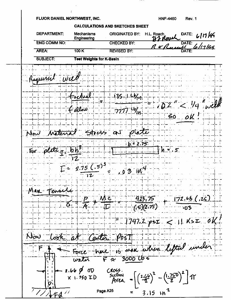
ORIGINAL FLUOR DANIEL
Fluor Daniel Hanfard, Inc. P.O. Box 1000 Richland, WA 99352
mil Z n w i c . To:
Fluor D.ni.1 Sanford ATTN: ACCOUNTS PAYABLE (31-80 Po Box 1000 RICBWIM) WA 99352
P1ra.m DSrsct Inquiriss to: STEVM 0. SlZclFER C.P.M. T i a m : CONTRACTING OFFICER Phon.: 509-373-7715 LXC:
F a : 509-376-9016
Vendor:
Michael L. Wilson WASRINGTON PUBLIC POWER SUPPLY PO BOX 968/MS-055 RICELAND WA 99352
Work Location:
Total VJu. : $5 .000 .00 VSSD Pric ing Idrthod: E S T m m
** NOT TO EXam **
/r D a h Signmd Dhonm Phons
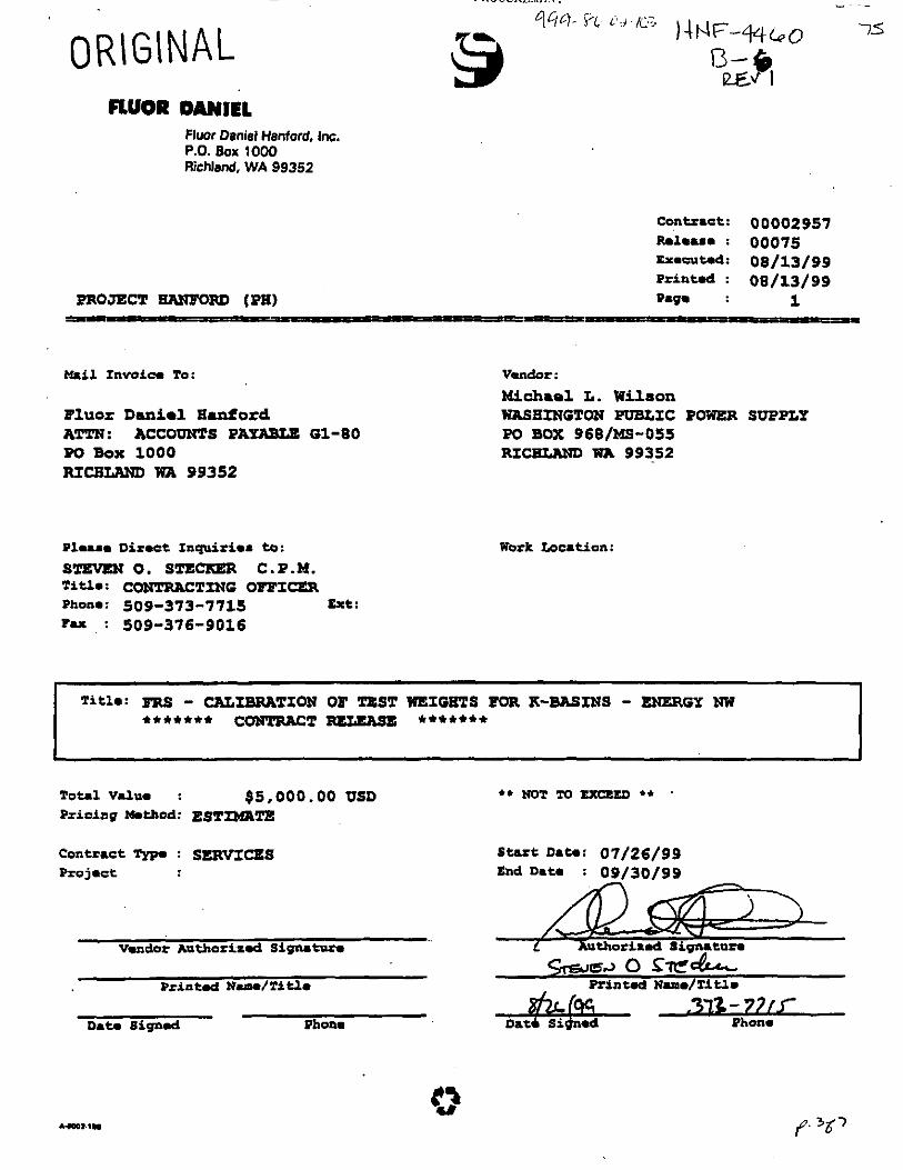
ORIGINAL 08/13/99 H.L. Roach/FDNW
STATEMENT OF WORK FOR
CaIibrtuootIon of Test Wekhts for &Basin
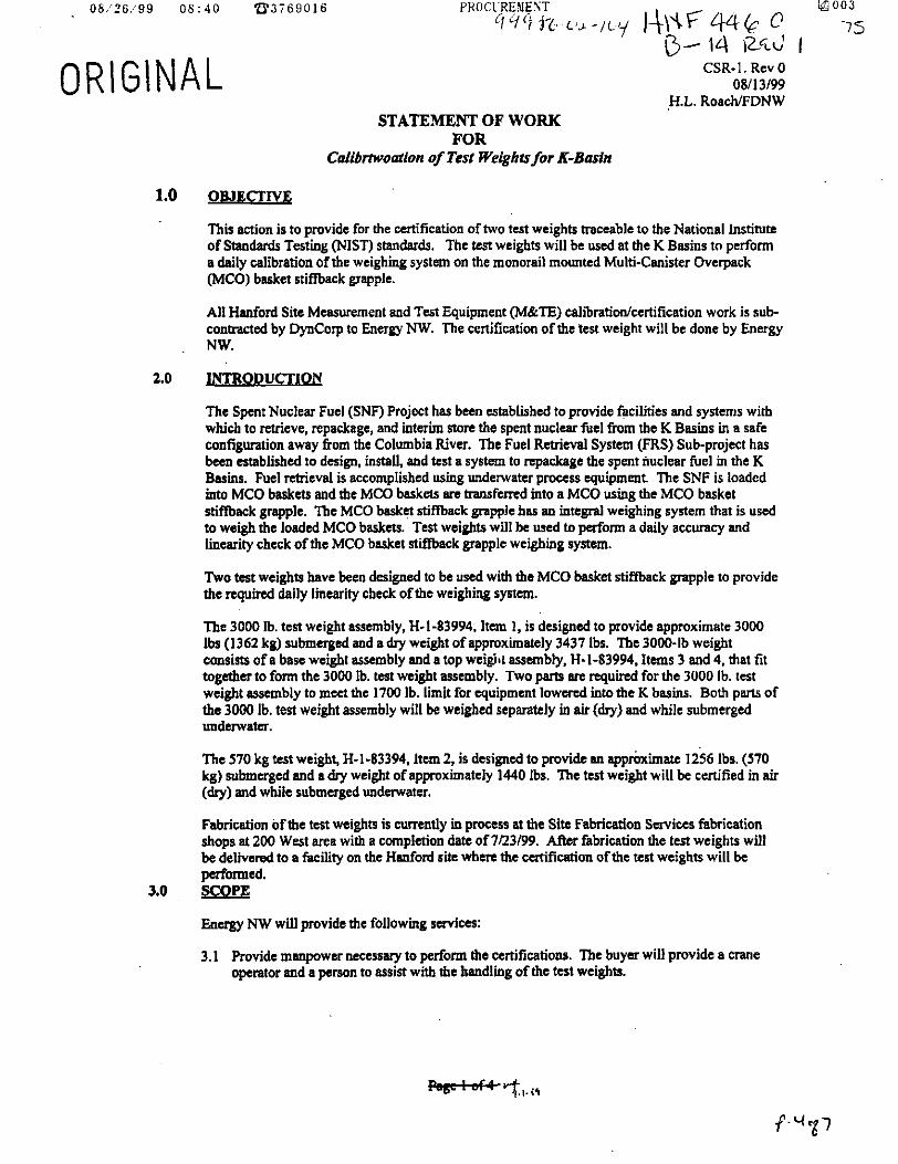
1.0 OBJECTIVE
This action is to provide for the certification of hvo test weights traceable to the National Institute of Standad Testing (NISI') standards. The test weights will be used at the K Basins to perform a daily calibration of the wcighiig system on the monorail mounted Multi-Canister Overpack (MCO) basket stiffbexk grapple.
AI1 Haford Site Measurement and Test Equipment @&IT) calibratiodcertificsaon work is sub- contracted by DynCorp to Energy NW. The cwtification of the test weight will be done by Energy NW.
2.0 INTRODUCTION
The Spent Nuclear Fuel (SNF) Project has been established to provide facilities and systms with which to retrieve. repackage, and interim store the spent nuclear fuel from the K Basins in a safe configauation away from the Columbia River. The Fuel Retrieval System (FRS) Subproject has been established to design, install, and test a system to repackage the spent nuclear fuel in the K Baris. Fuel ntrieval is accomplished using undewtcr p r o f n o equipment. The SNF is loaded into MCO baskets and the MCO baskets arc transferred into a MCO usig the MCO basket stiftback grapple. The MCO basket stiwack grapple has an integral weighing system that is used to weigh the loaded MCO bask-. Test weights will be used to paform a daily accuracy and lincsrity check of the MCO basket stifback grapple weighing system.
Two test weights have becn designed to be used with the MCO basket e a c k grapple to provide the required daily lincarny check of the weighing system.
'Ibe 3000 Ib. test weight asicmbly, H-1-83994. Item 1, is designed to provide approximate 3000 Ibs (1362 kg) submerged and a dry weight of appmximatcly 3437 Ibs. The 3000-lb weight consists of a tse weight assembly snd a top weight assembly, H-1-83994. Items 3 ann 4. that fit together to foran the 3000 Ib. test weight assembly. Two pam are required for the 3000 Ib. test weight wembly to men the 1700 Ib. limit for equipment lowered into the K basins. Both pans of the 3000 Ib. test weight assembly will be weighed sepmtely in air (dry) and while submerged underwater.
The 570 kg test weight, H-1-83394. ltun 2, is designed to provide an appmximate 1256 Ibs. (570 kg) mbmcrged and a dry weight of appmximately 1440 Ibs. The test weight will be certified in air (dry) and while submerged underwater.
Fabrication of the test weights is currently io pmcus at the Site Fabrication Services fibrication shops at 200 West area with a completion date of 7/23/99. After fabrication the test weights will be delivered to a ki l i ty on the Hanford sib w h m the certification ofthe test weights will be pwfomed.
Energy NW will provide me following rcm'ces:
3. I Rovide manpower me5sary to perform the certifications. The buyer will provide a crane operator and a penon to assist wtth the handling of the test weights.
3.0 SCopE

ORIGINAL CSR-I. Rev0 08/13/99
HJ,. RoaehlFDNw 3.2 Catify the tcn weights. 'Ihc tcn weights wiU be cntifitd for dry (in air) weight and for
Nbmcrgcd (underwater) weight The tCa weighb will be ccltified to +/4.5%. Tbe fOUOWing itenu will be C ~ l m t
0
0
€I-1-83994, Item 2.570 kg.Test Weight Asmbly
81-83994, Item 3, Bare Weight Asacmbly
61-83994, Item 4. Top Weight Assembly
3.3
3.4
3.5
Provide certification certificates for the two test weights items lined m 32. The certification catificster ahdll meet the quiremats of HNF-PRO-490, Rev I, Control ofMeasuring and Ta t Equipment.
The H a n f d Standads Lab (HSL) assigned ID number shall be marked on the top of each test might using %" high metal stamps.
The following outline rcpmcnts the major steps for test weight ccnifidm. A certification test plan wlll be written to dostanat the certification procedure.
3.5.1 The two test weights will be staged at the Hanford site facility selected by the buyer where the certification w& will be pntnmcd.
Buyer will provide a calibrated dynammeta that will be used for all ofthe wrtificstiOn testq. The dynamometer will be calibrated to NIST traceable Wdudr. HSL [Mt 545-29-06046.0-2000 Ib. w e , and be ~UXUEIC to +/- 0.1%.
Buyer will supply the d c d rigging device8 (slihgs, ttc) and water tank for
35.2
3.53 PerfOrmiPg mir w&
3.5.4 Ennpy NW will install the dynamometer on the ovuhead crane and prepare it for uac.
'ILC tcsf wcigl~f~ will be lifkd using the test weight sppsadp beam, H-I-83Y34, Itcm 7. 'Ihe buya will provide the spreader bwn.
The qxcader bum will be attached to the dynamometer and the dynamometer will be tared so that it indicatu zero load.
The test weigha will be lifted wing the spreader beam and the rlry weight will k m w d aad recorded. Thi will be repented three times.
Repsat steps 3.45 and 3.4.6 for the remaining two weights.
Remove the dynamometer and sprader bcam. Rccomcc4 the sprcdda bwn to the overhead m. Use the spreader beam to plncs the two test weights on the boaam of the watt% tank.
3.5.10 Disco~u~nst the spmdcr bar h the m e .
3.5.1 1 The spreader bar will be connected to a sling (>ZOO0 Ib capacity), the other ead of the ding will be e w n d to the bottom of the dynamometer and the c w c hook to the top of thc dynamornner. The sling must be of sufficient lm& to allow the dynamometer to be read when standing outside the water tanL.
3.5.5
3.5.6
3.5.7
3.5.8
3.5.9

CSR-I. Rev0 08/13/99
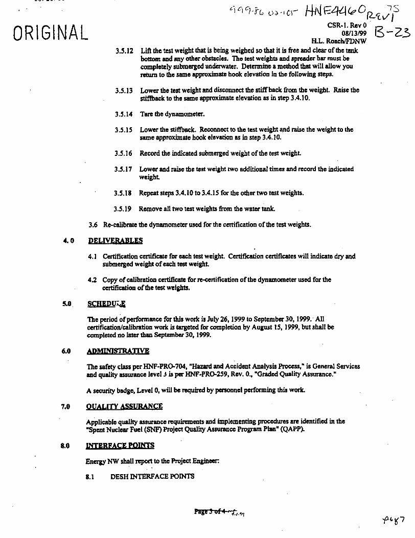
HL. RoachFDNW 3.5.12 Lift the test weight that is being weighed sa that it io free and clear of the t8nk
bottom and my other obstacles. The tost weights and 6pMdCr bar must be completely submerged undwwatcr. Determino a mcthod thnt will allow you return to the same approximate hook elevation in the following steps.
Lower the test weight and disconnect the stiff- fmn the weight. Raiie the RLftback to the same approximate elevation as in step 3.4.10.
3.5.13
3.5.14 Tare the dynamometer.
3.5.15 Lower the stiffback. Reconnect to the test weight and raise the weight to the same approximate hook elevation as in step 3.4.10.
3.5.16 Record the indicated submerged weight ofthe test weight.
3.5.17 Lower and raise the test weight two additional timu and record the indicated weight.
3.5.18 Repeatstq1~3.4.1Oto3.4.15forthcothatwo testweights.
3.5. I9 Remove all two test weights h m the water tank.
3.6 Re-calibrntc the dynamometer used for the certification of the test weights.
4.0 PELW-
4.1 Certification catif~iatc for each test weight. CatiGEation Certiticares will indicate dry and submerged weight of each ted weight.
4.2 Copy of Ealiiration ccrtificatc for re-certification of the dynamometer used for the catification of the test weights.
5.0 SCII&DULE
The period of pcrfomance for this work is July 26.1999 to September 30,1999. AI1 ontificatidcaliim work is targeted for completion by August 15.1999, but shall be completed no lata than September 30,1999.
6.0
The safety class per HNF-PRO-704, "Hazard and Accident Analysis Process," is Garral Services and quality assurance level 3 is pa "F-PRO-259, Rev. 0.. "Graded Quality Assurance."
A security badge, Lcvcl 0, wiil be nqvhrd by pasonacl pcrfonniag this work.
7.0 - B E Applicable quaIity assurance rcquimnents and implementing procedurt3 M identit& in the "Spent Nuclear Fuel (SNF) Project Quality Assurance Program Plan" (QAPP).
8.0 L Y T E R W O I N T S
Energy NW shall r r p ~ t to the hject Engineer:
8.1 DESH INTERFA'ACE POINTS

-' ofz.d P q & 4 - Y b O A - l Q 3 14 IW 44 68 CSR-I. Rev 0
08/13/99 H.L. RoacblFllNW
S.D.GodfrrY , 372-2927 J. M. Hmdasoa 376-8926 6. D. Gmth 313-6613
8.2 FDNW INTERFACE POINTS
FwEneineaing- Project Engiaccr
L. D. Kesole 376-1918 HL. Roach 376-5595
. p 'gl

ORIGINAL ) tdF 44G c
NORTH WEST Standards Laboratory
P b t Suppat Facility MDlols POBmW
Richlrd, WA 99353-0968 Phooe (SO9) 37-8131 FAX (909) 37%S2l9
Certificate of Cali brati on Manufacturer: SHOPMADE Model: NA
Asset Number: 999-8642-104 Serial Number: H-1-83994-030 Description: STAINLESS STEEL WEIGHT
Remrt Number: 935663880 Ref. Number: 75 Customer: STECKERSO
CALIBRATION INFORMATION L Test Conditions:
Calibration Date: 2aAug-99 Calibration Due: = A ~ ~ - o o Humidity: 0 !% Procedure I Rev: SLI 30-12 REV. 0 Technician: W. E. CALLAWAY Remarks: CALIBRATED IN 3OSBLDG-USED AT K-B.4SlN
TmperaNn: 0.0 C
Test Results:
Pass: Y Incomplete: N Limited: N As Pound: Pass As Left: Pass
ISTANDARDS USED FOR CALIBRATION h Asset Number hlWlfadWf? Model Description Calibration Date Due Date
545-29-06-046 MSI 7200 DYNAMOMETER . 21-Jan-99 2 1-Jan-00
NotdGeneral Conditions:
'Ik stlmdardc and caliiraion pmgram of the m y Noahwcst standards Labaatory complies with tk zquimnents of 10 CFR50 Appendix B a d ANSIINCSL 2-540-1. Unless d h e w i r n o t d The standards used in thir cdibration, desmi in the retatwed calibration prooccdurc with associated UnCcMlntl ' 'es o r l o l ~ . are vaccabl~ to thc ~ational la~tiane of sundards and ~ e c h ~ l o g y (NED. ~ b a c BR no spsial m o n s of use imposed on this item.
, exapt in ea withou uu pmission of tk ~ n p g y NOI~IIWCS~ standards ~abcaatory.
r 7-/- 99 , d D . H a r d M a n a g e r , Standards &ratory Date
p. 1537
NORTH WEST
ORIGINAL 1
CUSTOMER FLUOR DANIEL NORTHWEST
1 5 I4dF 4%G @ \3-12 ILW I
ANUFACTURER: MODEL'
SHOPMADE
EMARKS:
THE MSI-7200 DYNOMETER WAS FUNCTIONALLY TESTED AS PER AlTACHED REPORT DATED 8/6/99
NOMENCUNRE:
STAINLESS STEEL WEIGHT
.IBRATION DATA
SUBMERGED WT.
": 1-1-83 994- 030
2 7 Page ,of2 ' +
CAL CODE OR ID X: HUMIDITY: OSs-8(M2-104
4L DATE: DUE DATE: AS FOUND: AS LEFT: ' PROCEDURE:
0&3& 99 I 08-JL-00 New (&d/itlfl , S L l : 3 6 - 13- I rANDARDS USED:
MANUFACTURER: MODEL: CAL. CODE OR ID t: DUE DATE: ---

U M l l b / Y Y Ub:4U B 3 7 6 9 0 1 6
FLUOR DANIEL Fluor Daniel Hanford. Inc. P.O. Box 1 ow Richland, WA 99352
PROJZCT "FOIU, (PX)
Contract: 00002957 Releas- : 00075 Ex.nrt.d: 00/13/99 Printd : 08/13/99 Page : 1
m i l Invoice To:
Fluor Danio1 Iianford ATTN: ACCOVNTS PAYABLE 01-80 Po Box 1000 RICRLWD WA 99352
Phasm Diroct Inquiries to: s m m 0. sTEm C.P.M. Ti+h: CONTRACTING OFFICER Phone: 509-373-7715 Ext:
F a : 509-376-9016
Vendor : Michael L. Wilson WASHINGTON PUBLIC POWER SUPPLY PO BOX 968/MS-055 RICaWLND WA 99352
Work Loution:
T i t l e : FRS - CALIBRATION OF TEST WEIGHTS FOR X-BASINS - ENERGY NW ******* c-2 *******
Total Value : $5 ,000 .00 VSD Pricing Mmthod: EST^^
** NOT TO U a E D **
Contract Typa : SERVICES Star t Date: 07/26/99 Project End Date : 09/30/99
Vendor Authorized Signature < X t h o r i r d Siqnmture %%4Jor, 0 S t C L
Print& Name/Titlm - /J- Phon.
Printed Name/Title
D a t e B i g n d Pltone
p 3%7
08/26/99 0 8 : 4 0 2 3 3 7 6 9 0 1 6
ORIGINAL STATEMENT OF WORK
FOR Calibmodon of Test Weights for &Basin
CSR-I . Rev 0 08/13/99
H.L. RoacWFDNW
1.0 OBJECTIVE
This action is to provide for the certification of two test weights traceable to tbe National Institute of Standards Testing (NIST) standards. The test weights will be used at the K Basins to perform a daily calibration of the weighing system on the monorail mounted Multi-Canister Overpack (MCO) basket stiffback grapple.
All Hanford Site Measurement and Test Equipment (M&TE) calibratiodcertification work is sub- coneacted by DynCorp to Energy NW. The certification of the test weight will be done by Energy NW.
2.0 INTRODUCTION
The Spent Nuclear Fuel (SNF) Project has been established to provide facilities and systems with which to retrieve, repackage, and interim store the spent nuclear fuel from the K Basins in a safe configmtion away fiom the Columbia River. The Fuel Retrieval System (FRS) Subproject has been established to design, install, and test a system to repackage the spent nuclear fuel in the K Basins. Fuel retrieval is accomplished using undenvater process equipment. The SNF is loaded into MCO baskets and the MCO baskets arc transferred into a MCO using the MCO basket stif€back grapple. The MCO basket stiffback grapple has an integral weighing system that is used to weigh the loaded MCO baskets. Test weights will be used to perfom a daily accuracy and linearity check of the MCO basket stiffback grapple weighing system.
-0 test weights have been designed to be used with the MCO basket stiffback grapple to provide the required daily linearity check of the weighing system.
The 3000 Ib. test weight assembly, H-1-83994, Item 1, is designed to provide approximate 3000 Ibs (1362 kg) submerged and a dry weight of approximately 3437 Ibs. The 3000-lb weight consists of a base weight assembly and a top wei& assembly, H-1-83994, Items 3 and 4. that fit together to form the 3000 Ib. test weight assembly. Two parto are requited for the 3000 Ib. test weight assembly to meet the 1700 Ib. limit for equipment lowered into the K basins. Both p"s of the 3000 Ib. test weight assembly will be weighed separately in air (dry) and while submerged underwater.
The 570 kg test weight, H-1-83394. Item 2, is designed to provide an apprbximate 1256 Ibs. (570 kg) submerged and a dry weight of approximately 1440 Ibs. The test weight will be certified in air (dry) and while submerged underwater.
Fabrication of the test weight9 is c m U y in process at the Site Fabrication Services fabrication shops at 200 West area with a completion date of 7/23/99. ARct fabrication the test weights will be delivered to a facility on the Hdord site where the certification ofthe test weights will be performed.
3.0 SCopE
Energy NW will provide the following services:
3.1 Provide manpower nccesssry to perform the certifications. The buyer will provide a m e operator and a person to assist with the handling of the test weights.

08 /26 /99 08:41 8 3 7 6 9 0 1 6 PROCUEMEST @ 0 0 4
9yq-yL c&-/‘L~ 14NIzWbO&~’j 75 13- 1s
CSR-I . RCV 0 08/13/99
H.L. Roach/FDNW 0 R I GI NAL
3.2 Catify the test weighu. The test weights will be certified for dry (in air) weiglit and Tor submerged (Undcmater) weight. The test wcighb will be ccltifred to +/-0.5%. The following itmu will be certified:
H-1-83994, Itarm 2.570 kg.Te~I Weim Assably
H-1-83994, Item 3, Barc Weight Assembly
H-1-83994. Itan 4. Top Weight Assembly
3.3 Provide ccrtificution certificates for the two test weights items limed m 3.2. The certification certificdtca shdl mcct the rcquiremmts of HNF-PRO-490, Rev I, Control ojMurruing and Tar Egulpm~t .
3.4 The Hanford Smdards Lab (HSL) assigned ID number shall be marked on the top of each test weight using %” high metal stamps.
3 5 The followiq outline npnaents the major steps for test weight certification. A certification test plan will be written to document the ccrtlfication procedure.
3.5.1 The two tcst weights will be staged at the Hanford site facility selected by the buyer when the cdfication work will k performed.
Buyer will provide a cdibratcd dynamometer that will be used for all ofthe Ccrtificatirm tests. The dynamometer will be calibrated to NIST traceable stsodards, HSL IW1$45.29-060%, 0-2000 Ib. range, and b~ 0.1%.
Buyer will supply the mtified rigging devices (slings, ctc) and water tank for
3.52
to +I-
3.5.3 paformmg this work
3.5.4 Energy ?W will install the dynamometer on the ovd~ead crane and prepare it for use.
The ’mt wcighrs will be lifted using the test weight spreader b m , H-1-83994, ltan 7. The buyer will provide the spreader beam.
The sprrder beam will be attached to the dynamometer and the dynamomerm will be tand so that it indicates zero load.
The tcsl weights will be lifted wmg the spreader banm and the dry weight will k m c a S d and d e d . This will be repeated three thnes.
3.5.5
3.5.6
3.5.7
3.5.8
3.5.9
Repeat steps 3.4.5 acd3.4.6 forthe remaining two weigbts.
Remove the dynamom~ and spr?dder beam. Rcwnucct the s p d m beam to the ovahcad m e . Use the spadcrbsam to p l m the two test weights on the boaom of the water tank.
3.5.10 DiscoMwtthcspMderbarhtheaane.
3.5.1 I The spreader bar will be connected to a sling (>2000 Ib capacity), the other end of the sling will be connected to the botrom of the dynamometer and the m e hook to the top of the dynsmomcter. The sling must be of sufficient length to nllou, the dynamometer to be rend when standing outside the water rank

0 8 / 2 6 / 9 9 0 8 : 4 Z B3i69Ul6
0 R I GI NAL CSR-I.RW0 08/13/99
H.L. RoacWDNW 3.5.12 LiA the test weight that is being weighed so that it is free and clear of the tank
bottom and my other obstacles. The test weights and sprradcr bar must be completely submerged underwater. DacTmine a method that will allow you return to the same approximate hook elevation in the following steps.
3.5.13 Lower the test weight and discom.wl the stiffback from the weight. Raise the stiffback to the same approximate elevation as in step 3.4.10.
3.5.14 Tan the dynamometer.
3.5.15 Lower the stiffback. Reconnect to the test weight and raise the weight to the same approximate hook elevation as in step 3.4.10.
Record the indicated submerged weight of the test weight.
Lower and raise the test weight two additional times and record the indicated weight.
3.5.18 Repeat steps 3.4.10 to 3.4.15 for the other two test weights.
3.5.19 Remove all two test weights 6om the water tank.
3.6 Re-calibrate the dynamometer used for the certification of the test weights.
3.5.16
3.5.17
4.0
4.1 Certification cntificate for each test weight. Certification certificane will indicate dry and submerged weight of each test weight.
4.2 Copy of calibration certificate for n-certitication of the dynamometer used for the certification of the test weights.
5.0
The period of performance for this work is July 26,1999 to Scptembcr 30,1999. All &fication/ealibration work is targeted for completion by August 15, 1999. but shall be completed no later than September 30,1999.
6.0
'Ihe safety class per HNF-PRO-704, "Hazard and Accident Analysis Process." is General Services and quality a s ~ ~ a n c e level 3 is pn "F-PRO-259, Rev. 0.. "Graded Quality Assurance."
A scfurity badge, Level 0, will bc required by personnel pufwming this work
7.0 QUALITY ASSURA NCE
Applicable quality assurance requiransntr and lmplcmmting proccdurcs a n identified in the "Spcnt Nuclw Fuel (SNF) Project Quality Assurance Program Plan" (QAPP).
8.0 INTERFACE S
Energy NW shall report to the Pmject Engineer:
8.1 DESII INTERFACE POMTS

. 06 /26 /99 - 08:42 B 3 7 6 9 0 1 6
0 R I GI NAL
PRUCUHEMENT E4 006
qsq--SL? oa-toq 7s 13- 17 CSR-I. Rev 0
08/13/99 H.L. Roacb/FDNW
FRS DCPW Managm (Bw S.D.Godfrry . 312-2921
FRS Design Authority B. D. Groth 313-6613 1. M. Hendapon 376-8926 FRS Subproject Manager (Eiackup BTR)
8.2 FDNW INTERFACE POINTS
p W + f - k + 7 . I . ' f
L. D. Kesnie 376-1918 H.L. Roach 376-5595

ORIGINAL Q - 1% EMERGY NOR T i WEsf Standards Laboratory
Plant Supput Fscilily MD1OU,POBOx%8
Richlpld, WA 9935M968 Phme (W 371-8131 FAX (sos) 371-8219
Certificate of Calibration Manufacturer: SHOPMADE Model: NA
Asset Number: 999-86-02-105 Serial Number: H-143994420 Description: STAINLESS STEEL WEIGHT
Reuort Number: 935664420 Ref. Number: 75 customer: STECKERSO
lCALJBRAT1ON INFORMATION I Test Conditions:
Calibration Dare: 26Aug-99 Caliimion Due: 2 & ~ ~ ~ a Humidity: 0 % Pr&m / Rev: SLI 30-12 REV. 0 Technician: W. E. CALLAWAY Remarks: CALIBRATED AT 305BLDG-USED AT K-BASIN
Temperature: 0.0 C
Test Results
Pass: Y Incomplete: N Limited: N As Pound: pass As Left pass
ISTANDARDS USED FOR CALIBRATION b L I Asset Number Manufacturer Model Description Calibration Date Due Date - - 545-2%06-046 MSI 7200 DYNAMOMETER 21-lap99 21-lac-00
NotesIGened Conditions:
The standards and caliiration p m p m of the Energy Nonhwcst standards Laboratory complies with the r e q w of 10 CPR50 AppOaa B ami ANSINCSL Z - W l . Unhss dhewir noted: The aandards ustd m thir calibration, described in the r&'emxd falibratim pnxcdwe with assodroed unanamb ' 'es o r t o l m , are -le to tk Nntional Institme of standards and Technology (NIST). "e arc no spscial limairtim of use imposed on this ilem. Tbis Rep9 may nd bc rrprodycsa. except in ful l without tbe permission of the Energy Nonbwcst standards Laboratory.
y-/-PY Date

I ENERGY STANDARDS LABORATORY I NORTHWEST
CUSTOMER FLUOR DANIEL NORTHWEST
-75-
ORIGINAL
SHOPWDE STAINLESS STEEL WEIGHT sm: CAL CODE OR ID X: AMBIENT TEMP HUMIDITY:
CAL DATE: DUE DATE AS FOUND: AS LEFT: ' PROCEDURE: REV: &I- 839W-OJO I osk116-02-105 d/#
O J - J L - 94 08-2L-00 de& I h w d / w t l SLl: 30- 1 1 0 STANDARDS USED
MANUFACTURER MODEL: CAL. CODE OR ID #: DUE D A E --- MANUFACTURER; IMODEL
REPORT OF CALIBRATION
I REMARKS! , . .. .. ..
THE MSI-7200 DYNOMETER WAS FUNCTIONALLY l€STED AS PER AlTACHED REPORT DATED 8/6/99 I

ORIGINAL FLUOR DANIEL
Flwr Daniel Hanford, Inc. P.O. Box 1000 Richland, WA 99352
I D- 2 D
mil Invoic. To:
Fluor D a n i e l H d o r d
Po Box 1000 ATTN: ACCOUNTS PAYABLE G1-80
R I C R W WA 99352
Plm.8. Oimct Inquiri-a to: s- 0. STGCXER C . P . M . Titi*: CONTRACTING OFFICER Phon*: 509-373-7715 Ext: Fax : 509-376-9016
Vendor : Michaol L. Wilson WASHINGTON PUBLIC POWER SUPPLP PO BOX 968/MS-055 RIG- WA 99352
Work Location:
Total Value : $s,ooo.oo USD Pricing MdJaod: EST-m

ORIGINAL CSR- 1. Rev 0 08/13/99
H.L. RoachlFDNW STATEMENT OF WORK
FOR CaIibrtwootkm of Test Wetghtsfor K-Basin
1.0 OBJECTIVE
This action is to provide for the certification of two test weighk m e ~ b l e to the National Institute of Standards Testhg (NIST) standards. The test weights will be used at the K Basins to perform a daily calibration of the weighing system on the monorail mounted Multi-Canister Overpack (MCO) b d e t stiffbask grapple.
All Hanford Site Measurement and Test Equipment (MkTE) calibratiodccrtification work is sub- mhacted by DynCotp to Energy NW. The certification of the test weight will be done by Energy NW.
2.0 INTRODUCTION
The Spent Nuclear Fuel (SNF) Project has been established to provide facilities Md systems with which to retrieve. repackage, and interim smtc the spent nuclear fuel from the K Basins in a safe configuration away from the Columbia River. The Fuel Retrieval System (FRS) Subproject has been established to design, install, and test a system to repackage the spent nuclear fuel in the K Basins. Fuel retrieval is accomplished using underwater process equipment. The SNF is loaded mto MCO baskets and &e MCO bbskcts arc h a n s f d into a MCO using the MCO basket stif€back grapple. The MCO basket stifhck grapple has au integral weighing system that is used to weigh the loaded MCO baskets. Test weights will be used to perform a daily accuracy and linearity check of the MCO bslket stifback gra#le weighing system.
Two test weighk have b#n designed to be used with the MCO baske-t stiflback grapple to provide the required daily linearity check of the weighing system.
The 3000 Ib. test weight assembly, 81-83994, Itan 1, is designed to provide approximate 3000 Ibs (1362 kg) submerged and a dry weight of appmximatcly 3437 Ibs. The 3000-lb weight consists of a base weight azwaibly md a top weight assembly, H- 1-83994. Items 3 and 4. that tit together to form the 3000 ib. tost weight assembly. W o pans are q u k d for the 3000 Ib. test weight assembly to mea the I700 lb. limit for equipment lowered into the K basins. Both parts of the 3000 Ib. test weight assembly will be weigbcd separately in air (dry) and while submerged underwalcr.
The 570 kg test weighs H-1-83394. Item 2, is designed to provide M apprbximatc 1256 Ibs. (570 kg) submerged and a dry weight of approximately 1440 Ibs. The test weight will be certified in ab (dry) and while submerged underwater.
Fabrication of the test weights is currently in proceu at the Site Fabrication S m i c u fibtication shops at 200 West area with a completion date of 7/23/99. Alter fabrication the tm weights will be delivered to a facility on the Word site where the certification of the tcst weighk will be
Energy N W will provide the following services:
3.1 Provide manpowernccnsary to perfom the certifications. The buyer will provide a m e operator and a person to assist with the handling of the test weights.

" - - - - - - - . . - - .
M N c 4 4 w F id I 7 s Qi4Ci-%(, o r - /cs
CSR-I.Rev0 Gd22 08/13#9
ILL. RoachFDNW 3.2 C d f y the teat weight% The test weights will be certified for dry (in air) weight and for
submerged (underwater) weight The test weighb will be certified to +/4.5%. The following item will be certified:
ORIGINAL
H-1-83994, Itsm 2.570 kg Test Weight Assembly
H-1-83994, Item 3, Bare Weight Aambly
81-83994. Item 4. TOP Weight AasCmbly
3.3 Fmvide certification cmificates for the two tcst weights items lied in 3 2 . 'Ihe certification d u h r ahall meet the requirements of HNF-PRO-490, Rev 1, Control of Meuswing and rest Equipnulu.
3.4 The Hanford Standards Lab (HSL) assigned ID number &all be marked on the top of each test weight using %" high metal stamps.
3.5 The following outline represents the major steps for tmt weight ccnificdtion. A certification tat plan will be written to document the d c a t i o n procedure.
3.5.1 The two test weights will be staged at the Hanfwd slte facility selected by the buyer where. the catification wotlc will be performed.
Buyer will pron'de a calibrated dynamometer that will be used for all ofthe certification t e a . The dynamometer will be calibrated to NIST tractable StaD- HSL IWI 545-29.06046,0-2000 Ib. range, and be 0.1%.
Buycr will supply the Satified rigging devi- (slhgs, ctc) and water tank for
35.2
m +/-
3.5.3 paforming m u work
3.5.4 Energy NW will i n d l thc dynamometer on the ovuhcad crane and prepare it for ux.
35.5 The test weights will be lifted using the teat weight spMdcr bcam, H-I -83994. Item 7. The buyer will provide the sprradn beam.
Ibe Jpuda beam will be awhed to tho dynamometer and the dynamometer will be tand so that it indicakl zao load
The wt wcighb wlll be lifted using the s p d e r beam and the dry weight will k mcaaurui and rcwrdcd. l'hh will be repented three timu.
3.5.6
3.5.7
3.5.0 Rcpcatstepr3.4.5and3.4.6farthcmn*ningtwo weights.
3.5.9 Ranove the dynamometer and sprrader beam. Rcwmcct the s p d e r beam to the ovcrhcad cmw. Use the s p d e r beam to place the two test weights on the boaom of the water tank.
35.10 DtcoancatbespMderbarfmmd~eaane.
3.5.1 1 The s p d e r bar will be a m n d m a sling (>2000 Ib capaciy), the other end of the sling will be OOILntEbd to the bottom of the dynamometer and the crane hook to the top of the dynamometer. The sling must be of sufficient la& to d o w the dynamometer m be rend when standing outside the wntcr tank.
ORIGINAL CSR-I. Rev 0 08113f99 E-23 - -
H.L. RoachFDNW 3.5.12 Lift the test weight that is being weigbed so that it is h e aud clear of the tank
bottom md any other obstacles. The test weights and splradcr bar must be completely submerged undawater. Detcnniuc a mcthod that will allow you rrtum to the same approximate hook elevation In the following steps.
3.5.13 Lowex the test weight and ~ W C O M C C ~ the stiffback from the weight. Raise the stifltmk to the same approximate elevation as in stcp 3.4.10.
3.5.14 Tare the dynamometer.
3.5.15 Lower the stiffback. Reconnect to the test weight and raise the weight to the same approximate hook elevation 8s in step 3.4.10.
3.5.16 Record the indicated submerged weight ofthe test weight.
3.5.17 Lower and raise the test weight two additional times and record the indicated weight.
3.5.18 Repeat steps 3.4.10 to 3.4.15 for the other two test weights.
3.5.19 Remove all two test weights &om the water tank
3.6 Re-calibrate the dynamometer wed for the cmification of the test weights.
4.1 Certification cutifiicatc for each test weight. CcrtifKaton cmificatea will indicate dry and submerged weight of each tcJt weight.
43 Copy of calibration c d c a t c for re-certlfication of the dynamometer used for the cutificntion of the test weights.
5.0 ~ U ; ] e
The period of performance for this work h July 26,1999 to September 30,1999. All cerhficaliodcalibmtion work h targeted for complnion by August 15,1999, but shall be completed no later than septembu 30,1999.
6.0 ~ S l ' R A T M $
The safety class per "F-PRO-704, "Hazard and Accident Analysis Roccss." is General Services and guali assurance level J h par HNF-PRO-259, Rev. O., "Graded Quality Assurance."
A security badge, Level 0, will be required by personnel performing this w o k
7.0 - ! &
Applicable qualily assurance requirements and implementing proctduns arc identified in the "Spat Nuclsar Fuel (SNF) Project Quality Assurance Program Plan" (QAPP).
8.0 J N T E R W POINTS
Energy NW shall repon to the Project Engineer:
8.1 DESH INTERFACE POINTS

ORIGINAL S.D.Godfrry . 372-2921 J. M. Hmdapoa 376-8926 B. D. Glptb 373-6673
L. D. Kesoie 376-1918 H.L.. Roach 376-5595

![1 x Detection 10038 [P > 0.5 BAR] - Elfab · 2019. 1. 28. · 10038 [P > 0.5 BAR] 5 8 9 X3 Min X3 Min X3 Min X3 Min X3 X3 Ф T P Ф T T T T 1 x Detection 2 x Detection 6 7 Torque](https://img.pdfslide.us/doc/110x75/60ba177fcbcf900a842f11be/1-x-detection-10038-p-05-bar-elfab-2019-1-28-10038-p-05-bar.jpg)


![1173074 X3[1].1 Measurement Civil and Steel R_0, 02jan2012](https://img.pdfslide.us/doc/110x75/577cca0f1a28aba711a542ba/1173074-x311-measurement-civil-and-steel-r0-02jan2012.jpg)