Embed Size (px)
Citation preview
NOT A WALKWAY
N O T A W A L K W A Y
CLASS
CERTIFIED TO
CAN/CSA C22.2 NO. 247
CONFORMS TO
ANSI/UL-325
VEHICULAR GATE OPERATOR
HP
53382
MODEL
SERIAL
VOLTS
PHASE
AMPS
60 Hz
MAX GATE LOAD
DoorKing, Inc., I
nglewood, CA
MOVING ARM can
cause vehicle damage,
serious injury or d
eath.
STAY CLEAR of arm
at all tim
es.
NO: Pedestrians
Bicycles
Motorcycles
WARNING
Moving Gate Can Cause
Serious Injury or Death
KEEP CLEAR! Gate may move at any tim
e
without prior warning.
Do not let children operate the gate or p
lay
in the gate area.
This entrance is for vehicles only.
Pedestrians must use separate entra
nce.
MOVING ARM can
cause vehicle damage,
serious injury or d
eath.
STAY CLEAR of arm
at all tim
es.
NO: Pedestrians
Bicycles
Motorcycles
WARNING
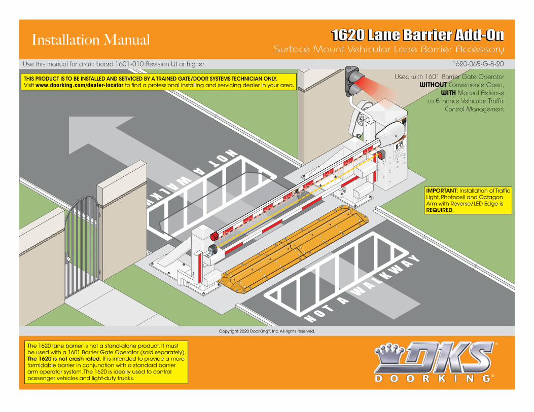
THIS PRODUCT IS TO BE INSTALLED AND SERVICED BY A TRAINED GATE/DOOR SYSTEMS TECHNICIAN ONLY. Visit www.doorking.com/dealer-locator to find a professional installing and servicing dealer in your area.
Used with 1601 Barrier Gate OperatorWITHOUT Convenience Open,
WITH Manual Releaseto Enhance Vehicular Traffic
Control Management
Installation Manual 1620 Lane Barrier Add-On1620 Lane Barrier Add-On1620 Lane Barrier Add-On1620 Lane Barrier Add-OnSurface Mount Vehicular Lane Barrier Accessory
Copyright 2020 DoorKing®, Inc. All rights reserved.
The 1620 lane barrier is not a stand-alone product. It must be used with a 1601 Barrier Gate Operator (sold separately).The 1620 is not crash rated. It is intended to provide a more formidable barrier in conjunction with a standard barrier arm operator system. The 1620 is ideally used to control passenger vehicles and light-duty trucks.
IMPORTANT: Installation of Traffic Light, Photocell and Octagon Arm with Reverse/LED Edge is REQUIRED.
Use this manual for circuit board 1601-010 Revision W or higher. 1620-065-G-8-20

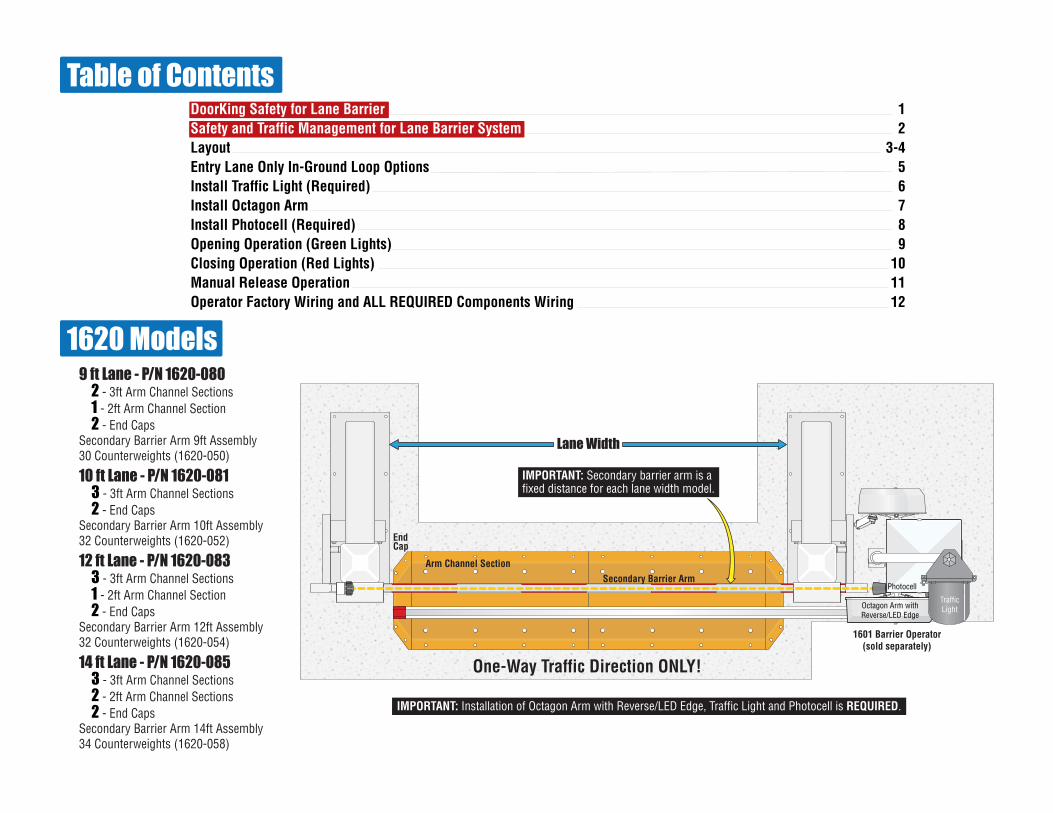
1620 Models
Table of Contents
Secondary Barrier Arm
1601 Barrier Operator(sold separately)
Lane Width
IMPORTANT: Secondary barrier arm is a fixed distance for each lane width model.
9 ft Lane - P/N 1620-080 2 - 3ft Arm Channel Sections 1 - 2ft Arm Channel Section 2 - End CapsSecondary Barrier Arm 9ft Assembly30 Counterweights (1620-050)
10 ft Lane - P/N 1620-081 3 - 3ft Arm Channel Sections 2 - End CapsSecondary Barrier Arm 10ft Assembly32 Counterweights (1620-052)
12 ft Lane - P/N 1620-083 3 - 3ft Arm Channel Sections 1 - 2ft Arm Channel Section 2 - End CapsSecondary Barrier Arm 12ft Assembly32 Counterweights (1620-054)
14 ft Lane - P/N 1620-085 3 - 3ft Arm Channel Sections 2 - 2ft Arm Channel Sections 2 - End CapsSecondary Barrier Arm 14ft Assembly34 Counterweights (1620-058)
12
3-456789
101112
DoorKing Safety for Lane BarrierSafety and Traffic Management for Lane Barrier SystemLayoutEntry Lane Only In-Ground Loop OptionsInstall Traffic Light (Required)Install Octagon ArmInstall Photocell (Required)Opening Operation (Green Lights)Closing Operation (Red Lights)Manual Release OperationOperator Factory Wiring and ALL REQUIRED Components Wiring
Arm Channel Section
EndCap
One-Way Traffic Direction ONLY!
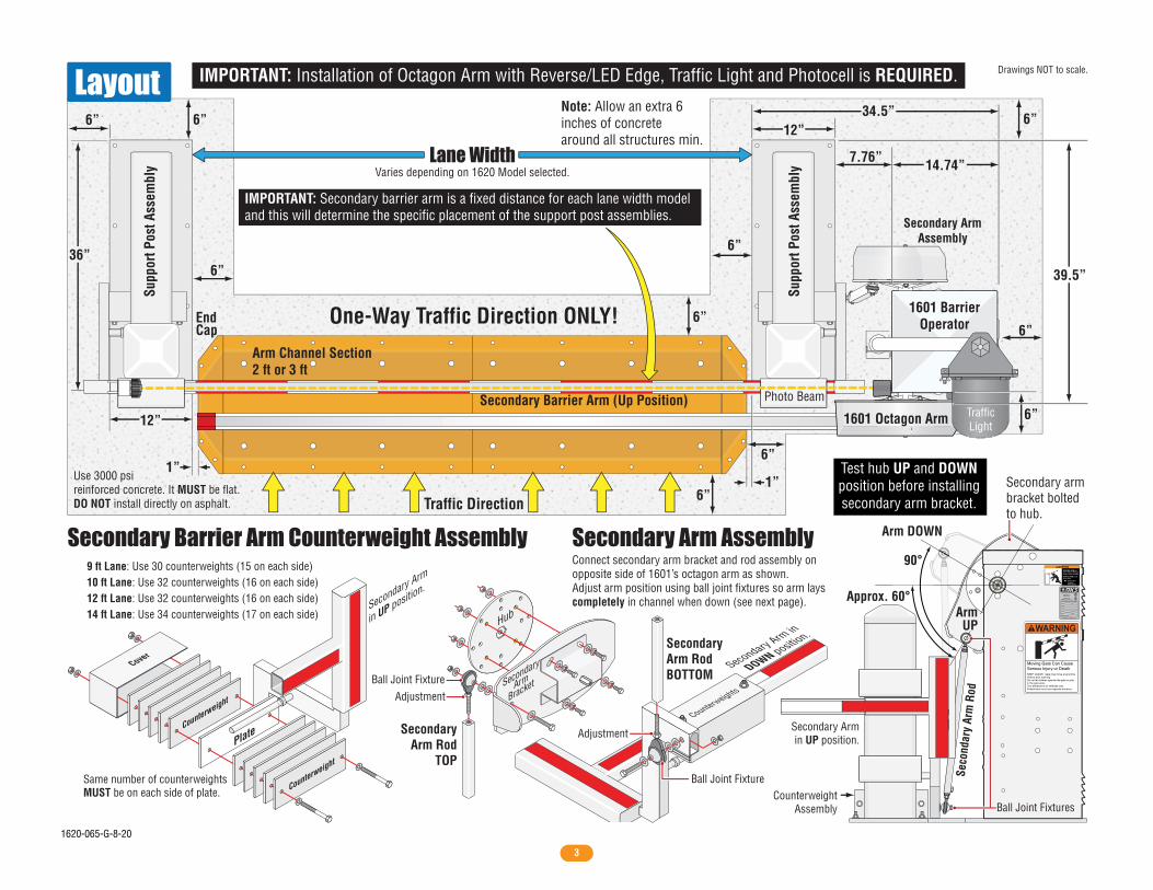
IMPORTANT: Installation of Octagon Arm with Reverse/LED Edge, Traffic Light and Photocell is REQUIRED.
Octagon Arm withReverse/LED Edge
Photocell
TrafficLight
1
1620-065-G-8-20
Moving Gate Can CauseSerious Injury or DeathKEEP CLEAR! Gate may move at any timewithout prior warning.Do not let children operate the gate or playin the gate area.This entrance is for vehicles only.Pedestrians must use separate entrance.
DoorKing Safety for Lane Barrier
NOT A WALKWAY
W A L K W A Y
CLASS
CERTIFIED TO
CAN/CSA C22.2 NO. 247
CONFORMS TO
ANSI/UL-325
VEHICULAR GATE OPERATOR
HP
53382
MODEL
SERIAL
VOLTS
PHASE
AMPS
60 Hz
MAX GATE LOAD
DoorKing, Inc., I
nglewood, CA
MOVING ARM can
cause vehicle damage,
serious injury or d
eath.
STAY CLEAR of arm
at all tim
es.
NO: Pedestrians
Bicycles
Motorcycles
WARNING
Moving Gate Can Cause
Serious Injury or Death
KEEP CLEAR! Gate may move at any tim
e
without prior warning.
Do not let children operate the gate or p
lay
in the gate area.
This entrance is for vehicles only.
Pedestrians must use separate entra
nce.
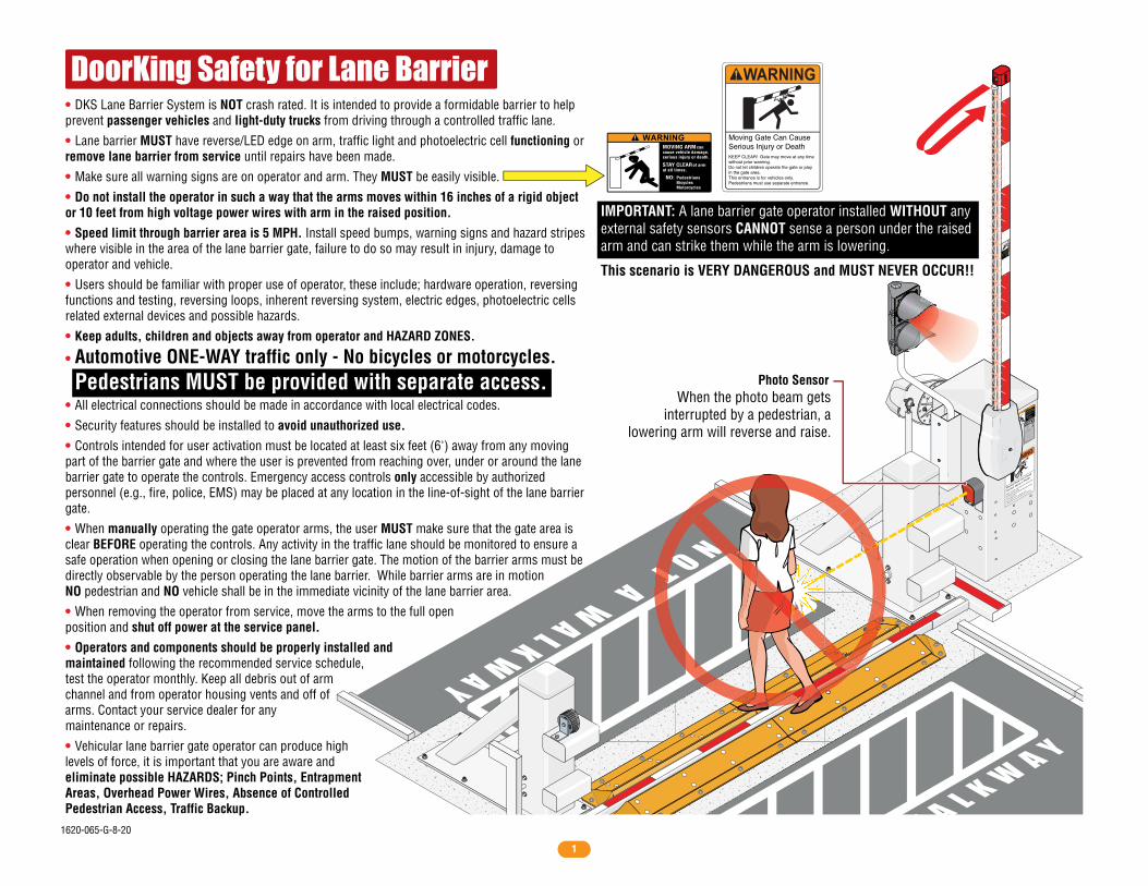
IMPORTANT: A lane barrier gate operator installed WITHOUT any external safety sensors CANNOT sense a person under the raised arm and can strike them while the arm is lowering.
This scenario is VERY DANGEROUS and MUST NEVER OCCUR!!
When the photo beam gets interrupted by a pedestrian, a
lowering arm will reverse and raise.
Photo Sensor
• DKS Lane Barrier System is NOT crash rated. It is intended to provide a formidable barrier to help prevent passenger vehicles and light-duty trucks from driving through a controlled traffic lane.
• Lane barrier MUST have reverse/LED edge on arm, traffic light and photoelectric cell functioning or remove lane barrier from service until repairs have been made.
• Make sure all warning signs are on operator and arm. They MUST be easily visible.
• Do not install the operator in such a way that the arms moves within 16 inches of a rigid object or 10 feet from high voltage power wires with arm in the raised position.
• Speed limit through barrier area is 5 MPH. Install speed bumps, warning signs and hazard stripes where visible in the area of the lane barrier gate, failure to do so may result in injury, damage to operator and vehicle.
• Users should be familiar with proper use of operator, these include; hardware operation, reversing functions and testing, reversing loops, inherent reversing system, electric edges, photoelectric cells related external devices and possible hazards.
• Keep adults, children and objects away from operator and HAZARD ZONES.
• Automotive ONE-WAY traffic only - No bicycles or motorcycles.Pedestrians MUST be provided with separate access.
• All electrical connections should be made in accordance with local electrical codes.
• Security features should be installed to avoid unauthorized use.
• Controls intended for user activation must be located at least six feet (6') away from any moving part of the barrier gate and where the user is prevented from reaching over, under or around the lane barrier gate to operate the controls. Emergency access controls only accessible by authorized personnel (e.g., fire, police, EMS) may be placed at any location in the line-of-sight of the lane barrier gate.
• When manually operating the gate operator arms, the user MUST make sure that the gate area is clear BEFORE operating the controls. Any activity in the traffic lane should be monitored to ensure a safe operation when opening or closing the lane barrier gate. The motion of the barrier arms must be directly observable by the person operating the lane barrier. While barrier arms are in motionNO pedestrian and NO vehicle shall be in the immediate vicinity of the lane barrier area.
• When removing the operator from service, move the arms to the full open position and shut off power at the service panel.
• Operators and components should be properly installed and maintained following the recommended service schedule, test the operator monthly. Keep all debris out of arm channel and from operator housing vents and off of arms. Contact your service dealer for any maintenance or repairs.
• Vehicular lane barrier gate operator can produce high levels of force, it is important that you are aware and eliminate possible HAZARDS; Pinch Points, Entrapment Areas, Overhead Power Wires, Absence of ControlledPedestrian Access, Traffic Backup.
OT
N
2
1620-065-G-8-20
Safety and Traffic Management for Lane Barrier System
NOT A WALKWAY
A W A L K W A Y
CLASS
CERTIFIED TO
CAN/CSA C22.2 NO. 247
CONFORMS TO
ANSI/UL-325
VEHICULAR GATE OPERATOR
HP
53382
MODEL
SERIAL
VOLTS
PHASE
AMPS
60 Hz
MAX GATE LOAD
DoorKing, Inc., I
nglewood, CA
MOVING ARM can
cause vehicle damage,
serious injury or d
eath.
STAY CLEAR of arm
at all tim
es.
NO: Pedestrians
Bicycles
Motorcycles
WARNING
Moving Gate Can Cause
Serious Injury or Death
KEEP CLEAR! Gate may move at any tim
e
without prior warning.
Do not let children operate the gate or p
lay
in the gate area.
This entrance is for vehicles only.
Pedestrians must use separate entra
nce.
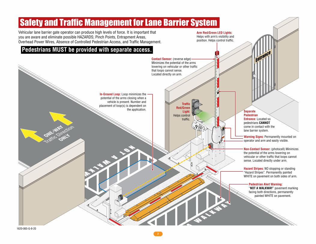
Non-Contact Sensor: (photocell) Minimizes the potential of the arms lowering on vehicular or other traffic that loops cannot sense. Located directly under arm.
Contact Sensor: (reverse edge) Minimizes the potential of the arms lowering on vehicular or other traffic that loops cannot sense.Located directly on arm.
Traffic Red/Green
Light:Helps control
traffic.
Arm Red/Green LED Lights: Helps with arm’s visibility and position. Helps control traffic.
SeparatePedestrianEntrance: Located so pedestrians CANNOT come in contact with the lane barrier system.
In-Ground Loop: Loop minimizes the potential of the arms closing when a
vehicle is present. Number and placement of loop(s) is dependent on
the application.
Warning Signs: Permanently mounted on operator and arm and easily visible.
Hazard Stripes: NO stopping or standing “Hazard Stripes”. Permanently painted WHITE on pavement on both sides of arm.
Pedestrian Alert Warning:“NOT A WALKWAY” pavement marking facing both directions, permanently
painted WHITE on pavement.
Vehicular lane barrier gate operator can produce high levels of force. It is important that you are aware and eliminate possible HAZARDS; Pinch Points, Entrapment Areas, Overhead Power Wires, Absence of Controlled Pedestrian Access, and Traffic Management.
ONE-WAY
Traffic Direction
ONLYEntrance
Pedestrians MUST be provided with separate access.
3
1620-065-G-8-20
SecondaryArm Rod
TOP
AdjustmentBall Joint Fixture
Traffic Direction
One-Way Traffic Direction ONLY!
Secondary ArmAssembly
Secondary Arm Assembly
Secondary armbracket boltedto hub.
Seco
ndar
y Ar
m R
od
Secondary Barrier Arm (Up Position)
Arm Channel Section2 ft or 3 ft
EndCap
1601 Octagon Arm
1601 BarrierOperator
Supp
ort P
ost A
ssem
bly
Supp
ort P
ost A
ssem
bly
Lane WidthVaries depending on 1620 Model selected.
12”
12”
36”
6”
6”
6”
6”
6”
6”
1”1”
6” 6” 6”
6”
Use 3000 psireinforced concrete. It MUST be flat.DO NOT install directly on asphalt.
Secondary Barrier Arm Counterweight Assembly
Same number of counterweightsMUST be on each side of plate.
9 ft Lane: Use 30 counterweights (15 on each side)10 ft Lane: Use 32 counterweights (16 on each side)12 ft Lane: Use 32 counterweights (16 on each side)14 ft Lane: Use 34 counterweights (17 on each side)
Photo Beam
Note: Allow an extra 6 inches of concrete around all structures min.
IMPORTANT: Secondary barrier arm is a fixed distance for each lane width model and this will determine the specific placement of the support post assemblies.
Connect secondary arm bracket and rod assembly on opposite side of 1601’s octagon arm as shown.Adjust arm position using ball joint fixtures so arm lays completely in channel when down (see next page).
Plate
Counterweight
Counterweight
Cover
39.5”
CLASS
CERTIFIED TOCAN/CSA C22.2 NO. 247
CONFORMS TOANSI/UL-325
VEHICULAR GATE OPERATOR
HP
53382
MODEL
SERIAL
VOLTS PHASE
AMPS 60 Hz
MAX GATE LOAD
DoorKing, Inc., Inglewood, CA
MOVING ARM cancause vehicle damage,serious injury or death.
STAY CLEAR of armat all times.
NO: PedestriansBicyclesMotorcycles
WARNING
Moving Gate Can CauseSerious Injury or DeathKEEP CLEAR! Gate may move at any timewithout prior warning.Do not let children operate the gate or playin the gate area.This entrance is for vehicles only.Pedestrians must use separate entrance.
Arm DOWN
ArmUP
90°
Approx. 60°
CounterweightAssembly
Secondary Armin UP position.
Ball Joint Fixtures
Test hub UP and DOWN position before installing secondary arm bracket.
Hub
Secondary
Arm
Bracket
TrafficLight
34.5”
14.74”7.76”
LayoutDrawings NOT to scale.
Adjustment
SecondaryArm RodBOTTOM
Ball Joint Fixture
CounterweightsSecondary Arm in
DOWN position.
Secondary Arm
in UP position.
IMPORTANT: Installation of Octagon Arm with Reverse/LED Edge, Traffic Light and Photocell is REQUIRED.
4
1620-065-G-8-20
Layout
Octagon Arm Down
Reverse/LED EdgeCLASS
CERTIFIED TOCAN/CSA C22.2 NO. 247
CONFORMS TOANSI/UL-325
VEHICULAR GATE OPERATOR
HP
53382
MODEL
SERIAL
VOLTS PHASE
AMPS 60 Hz
MAX GATE LOAD
DoorKing, Inc., Inglewood, CA
MOVING ARM cancause vehicle damage,serious injury or death.
STAY CLEAR of armat all times.
NO: PedestriansBicyclesMotorcycles
WARNING
Moving Gate Can CauseSerious Injury or DeathKEEP CLEAR! Gate may move at any timewithout prior warning.Do not let children operate the gate or playin the gate area.This entrance is for vehicles only.Pedestrians must use separate entrance.
Wire Mesh
Conduit
Wire Mesh
Arm ChannelArm Down
Secondary ArmSee previous page.
Seco
ndar
y Ar
m R
odSecondary Barrier Arm (Up Position)
6”Min
33.5”
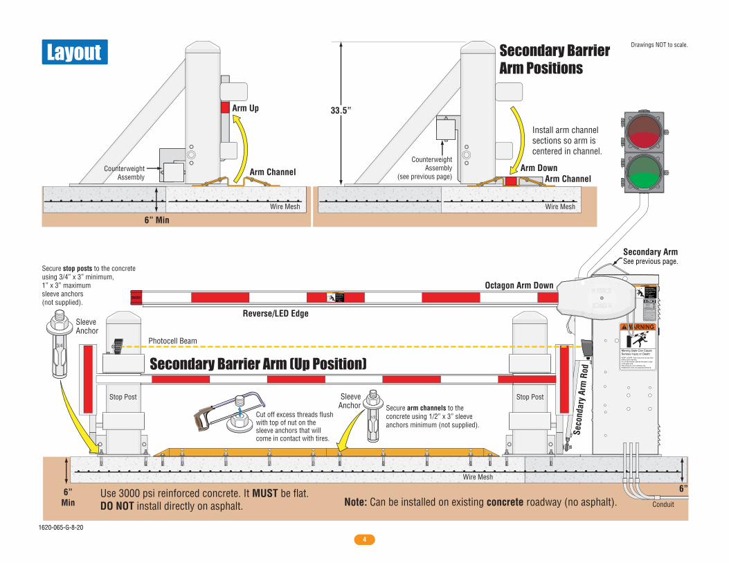
6”Use 3000 psi reinforced concrete. It MUST be flat.DO NOT install directly on asphalt. Note: Can be installed on existing concrete roadway (no asphalt).
Install arm channel sections so arm is centered in channel.
SleeveAnchor
SleeveAnchor
Photocell Beam3/4
1/2
Secure stop posts to the concrete using 3/4” x 3” minimum,1” x 3” maximumsleeve anchors(not supplied).
Secure arm channels to the concrete using 1/2” x 3” sleeve anchors minimum (not supplied).
Cut off excess threads flush with top of nut on the sleeve anchors that will come in contact with tires.
Drawings NOT to scale.
CounterweightAssembly
(see previous page)
Wire Mesh
Arm Channel
Arm Up
Secondary BarrierArm Positions
CounterweightAssembly
6” Min
MOVING ARM cancause vehicle damage,serious injury or death.
STAY CLEAR of armat all times.
NO: PedestriansBicyclesMotorcycles
WARNING
Stop Post Stop Post
5
1620-065-G-8-20
Arming Loopfor Access Control Device
(Optional)OR
Ticket Eject Loopfor Ticket Spitter (Required)
9409
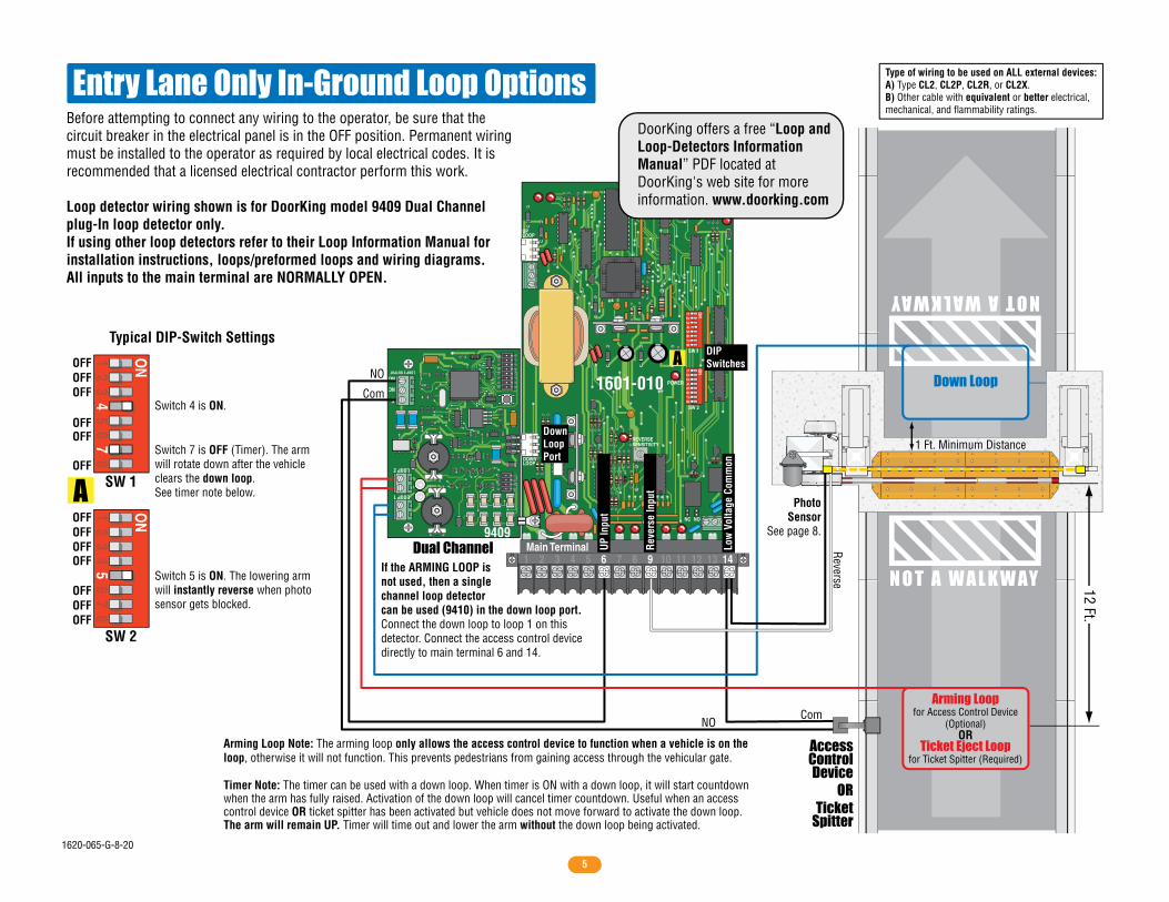
Entry Lane Only In-Ground Loop OptionsBefore attempting to connect any wiring to the operator, be sure that the circuit breaker in the electrical panel is in the OFF position. Permanent wiring must be installed to the operator as required by local electrical codes. It is recommended that a licensed electrical contractor perform this work.
Loop detector wiring shown is for DoorKing model 9409 Dual Channel plug-In loop detector only.If using other loop detectors refer to their Loop Information Manual for installation instructions, loops/preformed loops and wiring diagrams. All inputs to the main terminal are NORMALLY OPEN.
Dual Channel
REVERSESENSITIVITY
TIMEDELAY
SW 1
SW 2
POWER
1 ON2
34
56
78
1 ON2
34
56
78
NC NO
UPLOOP
DOWNLOOP
1 2 3 4 5 6 7 8 9 10 11 12 13 14
1601-010
AccessControlDevice
ORTicket
Spitter
ComNO
Com
NOA
A
If the ARMING LOOP is not used, then a single channel loop detector can be used (9410) in the down loop port. Connect the down loop to loop 1 on this detector. Connect the access control device directly to main terminal 6 and 14.
Arming Loop Note: The arming loop only allows the access control device to function when a vehicle is on the loop, otherwise it will not function. This prevents pedestrians from gaining access through the vehicular gate.
Timer Note: The timer can be used with a down loop. When timer is ON with a down loop, it will start countdown when the arm has fully raised. Activation of the down loop will cancel timer countdown. Useful when an access control device OR ticket spitter has been activated but vehicle does not move forward to activate the down loop.The arm will remain UP. Timer will time out and lower the arm without the down loop being activated.
Switch 4 is ON.
Switch 7 is OFF (Timer). The arm will rotate down after the vehicle clears the down loop.See timer note below.
Switch 5 is ON. The lowering arm will instantly reverse when photo sensor gets blocked.
SW 1
1 ON2
34
56
78
SW 2
1 ON2
34
56
78
Main Terminal
Type of wiring to be used on ALL external devices:A) Type CL2, CL2P, CL2R, or CL2X. B) Other cable with equivalent or better electrical,mechanical, and flammability ratings.
Down Loop
1 Ft. Minimum Distance
12 Ft.
N O T A W A L K W AYNOT A WALKWAY
DoorKing offers a free “Loop and Loop-Detectors Information Manual” PDF located at DoorKing's web site for more information. www.doorking.com
PhotoSensor
See page 8.
ReverseTypical DIP-Switch Settings
OFF
OFFOFF
OFFOFFOFF
OFFOFF
OFFOFF
OFFOFFOFF
Low
Vol
tage
Com
mon
Reve
rse
Inpu
t
UP In
put
DownLoopPort
DIPSwitches
6
1620-065-G-8-20
SupportPostBracket
Bracket
Cover
U-Bolt
Clamp
Access Door
U-Bolt
Clamp
Route6 ft cablethroughhole.
Elbow
Support Post
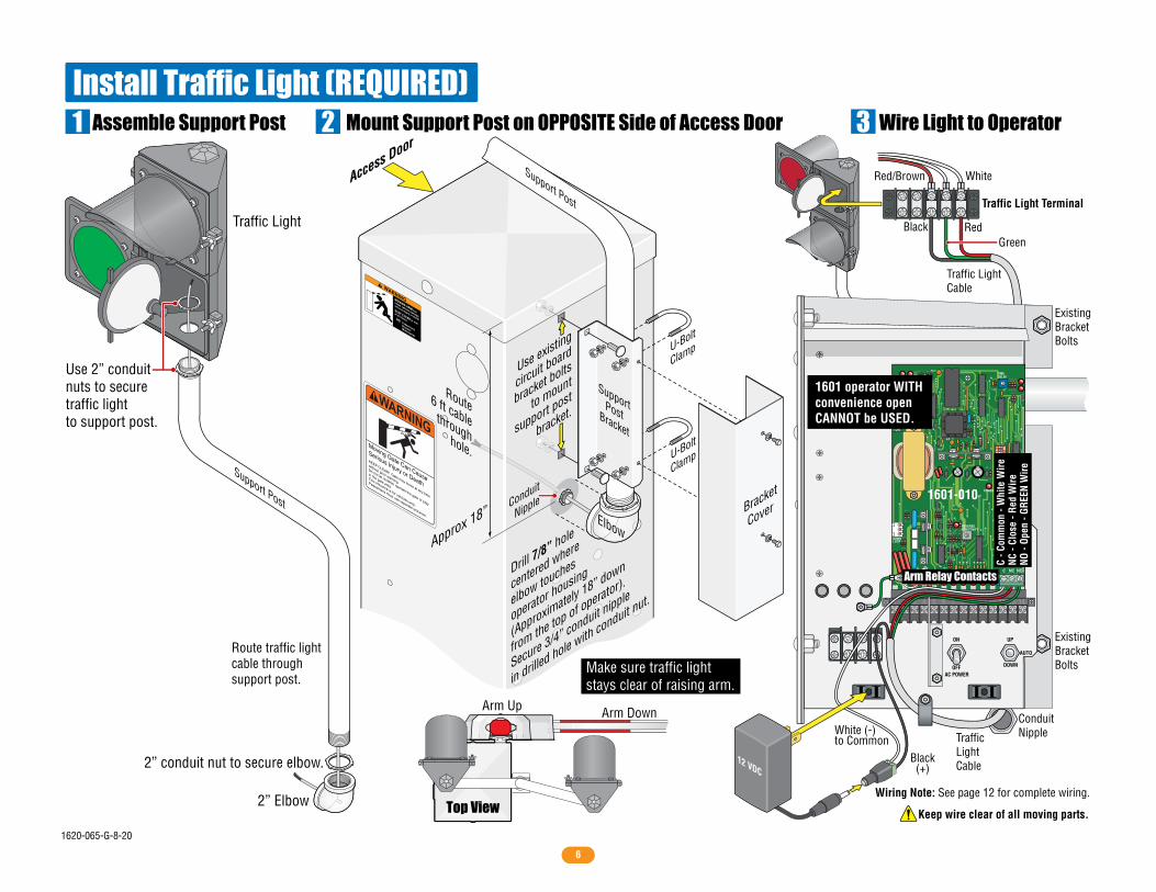
Use existing
circuit board
bracket bolts
to mount
support post
bracket.
Drill 7/8” hole
centered where
elbow touches
operator housing
(Approximately 18” down
from the top of operator).
Secure 3/4” conduit nipple
in drilled hole with conduit n
ut.
Route traffic lightcable throughsupport post.
Install Traffic Light (REQUIRED)Assemble Support Post Mount Support Post on OPPOSITE Side of Access Door Wire Light to Operator1 2 3
REVERSESENSITIVITY
TIMEDELAY
POWER
1 ON2
34
56
78
1 ON2
34
56
78
NCNO
UPLOOP
DOWNLOOP
1 2 3 4 5 6 7 8 9 10 11 12 13 14
SW 1
SW 2
ON
OFFAC POWER
AUTO
DOWN
UP
ConduitNipple
Traffic Light Terminal
Red
TrafficLightCable
Traffic LightCable
GreenBlack
Black(+)
Keep wire clear of all moving parts.
NONCC
Moving Gate Can Cause
Serious Injury or Death
KEEP CLEAR! Gate may move at any time
without prior warning.
Do not let children operate the gate or play
in the gate area.
This entrance is for vehicles only.
Pedestrians must use separate entrance.
Conduit
Nipple
ExistingBracketBolts
ExistingBracketBolts
1601 operator WITH convenience open CANNOT be USED.
C - C
omm
on -
Whi
te W
ireNC
- Cl
ose
- Red
Wire
NO -
Open
- GR
EEN
Wire
Arm Relay Contacts
1601-010
White (-)to Common
12 VDC
Approx 18”
Make sure traffic lightstays clear of raising arm.
Arm DownArm Up
2” conduit nut to secure elbow.
Use 2” conduitnuts to secure traffic lightto support post.
Traffic Light
Top View2” Elbow
Support Post
WhiteRed/Brown
Wiring Note: See page 12 for complete wiring.
7
1620-065-G-8-20
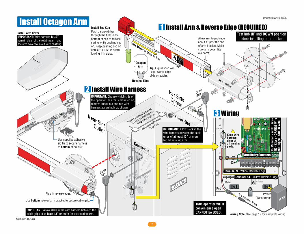
Slide Reverse Edge on Arm
Drawings NOT to scale.
Install Octagon Arm1
2
REVERSESENSITIVITY
TIMEDELAY
POWER
1 ON2
34
56
78
1 ON2
34
56
78
NCNO
UPLOOP
DOWNLOOP
1 2 3 4 5 6 7 8 10 11 12 13
SW 1
SW 2
ON
OFFAC POWER
AUTO
DOWN
UP
NONCC
Red+
Black-
PowerTransformer
(1601-345)
Transformer Plug
C - C
omm
on -
WHI
TE W
ireNC
- Cl
ose
- ORA
NGE
Wire
NO -
Open
- GR
EEN
Wire
Keep wireharnessclear ofall movingparts.
Arm Relay Contacts
Terminal 9 - Yellow Reverse Edge
Terminal 14 - Yellow Reverse EdgeCable
Grip
Cable
Grip
Cable
Grip
Knock-Out
Knock-Out
Far SideOption
Near SideOption
Use bottom hole on arm bracket to secure cable grip.
Plug in reverse edge.
Wire Harness Secured
to Top of Cabinet for
FAR side option
Included Adhesive
Zip Ties
Use supplied adhesive zip tie to secure harness to bottom of bracket.
IMPORTANT: Choose which side of the operator the arm is mounted on, remove knock-out and run wire harness accordingly as shown.
Test hub UP and DOWN position before installing arm bracket.Allow arm to protrude
about 1” past the end of arm bracket. Make sure arm cover fits over arm.
Arm Bracket
Hub
Reverse Edge
OctagonArm
Install End Cap
Install Wire Harness
Install Arm & Reverse Edge (REQUIRED)
Wiring
Push a screwdriver through the hole in the bottom of cap to release spring while pushing cap on. Keep pushing cap on until a “CLICK” is heard, locking it in place.
1601 operator WITH convenience open CANNOT be USED.
Install Arm CoverIMPORTANT: Wire harness MUST remain clear of the rotating arm and the arm cover to avoid wire chaffing.
3
Tip: Liquid soap will help reverse edge slide on easier.
Wiring Note: See page 12 for complete wiring.
1601-010IMPORTANT: Allow slack in the wire harness between the cable grips of at least 13” or more for the rotating arm.
IMPORTANT: Allow slack in the wire harness between the cable grips of at least 13” or more for the rotating arm.
9 14
12 VDC
8
1620-065-G-8-20
S6 AC10-25VDC12-30V
Power Relay
NO NC COM
NOT A WALKWAY
N O T A W A L K W A Y
REVERSESENSITIVITY
SW 2
POWER
23
45
67
8
NC NO
DOWNLOOP
1 2 3 4 5 6 7 8 9 10 11 12 13 14
1601
Main Terminal
CLASS
CERTIFIED TO
CAN/CSA C22.2 NO. 247
CONFORMS TO
ANSI/UL-325
VEHICULAR GATE OPERATOR
HP
53382
MODEL
SERIAL
VOLTS
PHASE
AMPS
60 Hz
MAX GATE LOAD
DoorKing, Inc., I
nglewood, CA
MOVING ARM can
cause vehicle damage,
serious injury or d
eath.
STAY CLEAR of arm
at all tim
es.
NO: Pedestrians
Bicycles
Motorcycles
WARNING
Moving Gate Can Cause
Serious Injury or Death
KEEP CLEAR! Gate may move at any tim
e
without prior warning.
Do not let children operate the gate or p
lay
in the gate area.
This entrance is for vehicles only.
Pedestrians must use separate entra
nce.
MOVING ARM can
cause vehicle damage,
serious injury or d
eath.
STAY CLEAR of arm
at all tim
es.
NO: Pedestrians
Bicycles
Motorcycles
WARNING
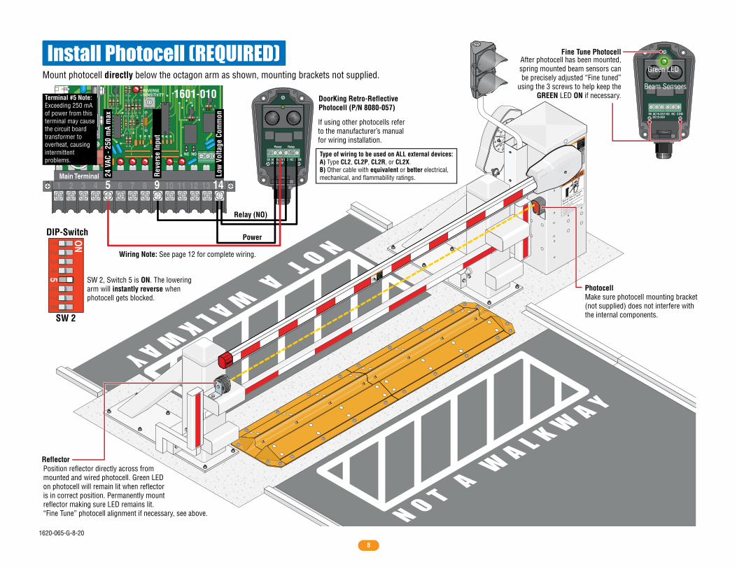
Install Photocell (REQUIRED)Mount photocell directly below the octagon arm as shown, mounting brackets not supplied.
Type of wiring to be used on ALL external devices:A) Type CL2, CL2P, CL2R, or CL2X. B) Other cable with equivalent or better electrical,mechanical, and flammability ratings.Lo
w V
olta
ge C
omm
on
Reve
rse
Inpu
t
24 V
AC -
250
mA
max
DoorKing Retro-ReflectivePhotocell (P/N 8080-057)
Relay (NO)
Power
If using other photocells refer to the manufacturer’s manual for wiring installation.
Reflector
SW 2, Switch 5 is ON. The lowering arm will instantly reverse when photocell gets blocked.
SW 2
1 ON2
34
56
78
DIP-Switch
1601-010
PhotocellMake sure photocell mounting bracket (not supplied) does not interfere with the internal components.
S6 AC10-25VDC12-30V
NO NC COM
Beam Sensors
After photocell has been mounted, spring mounted beam sensors can be precisely adjusted “Fine tuned”
using the 3 screws to help keep the GREEN LED ON if necessary.
Green LED
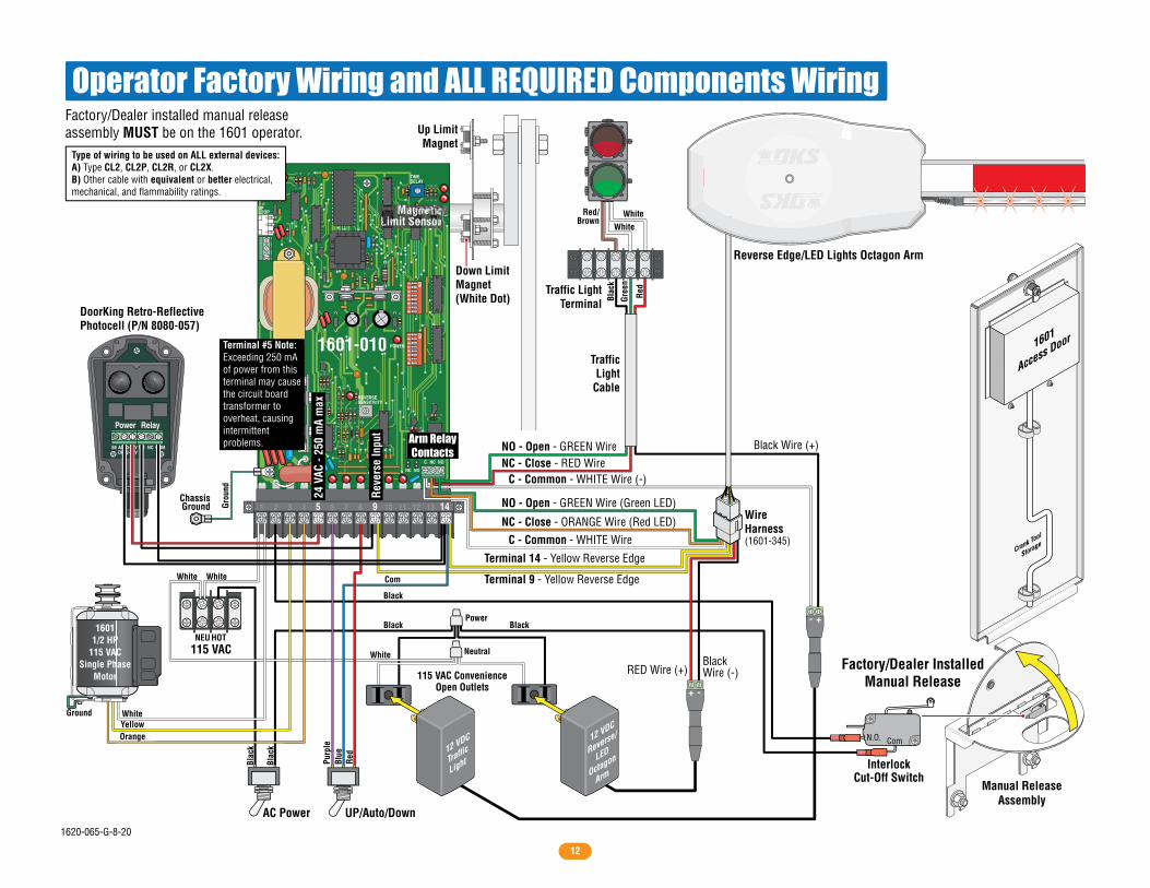
Terminal #5 Note:Exceeding 250 mA of power from this terminal may cause the circuit board transformer to overheat, causing intermittent problems.
Position reflector directly across from mounted and wired photocell. Green LED on photocell will remain lit when reflector is in correct position. Permanently mount reflector making sure LED remains lit. “Fine Tune” photocell alignment if necessary, see above.
Fine Tune Photocell
Wiring Note: See page 12 for complete wiring.
9
1620-065-G-8-20
NOT A WALKWAY
N O T A W A L K W A Y
ONE-WAY
Traffic Direction
ONLY
CLASS
CERTIFIED TO
CAN/CSA C22.2 NO. 247
CONFORMS TO
ANSI/UL-325
VEHICULAR GATE OPERATOR
HP
53382
MODEL
SERIAL
VOLTS
PHASE
AMPS
60 Hz
MAX GATE LOAD
DoorKing, Inc., I
nglewood, CA
MOVING ARM can
cause vehicle damage,
serious injury or d
eath.
STAY CLEAR of arm
at all tim
es.
NO: Pedestrians
Bicycles
Motorcycles
WARNING
Moving Gate Can Cause
Serious Injury or Death
KEEP CLEAR! Gate may move at any tim
e
without prior warning.
Do not let children operate the gate or p
lay
in the gate area.
This entrance is for vehicles only.
Pedestrians must use separate entra
nce.
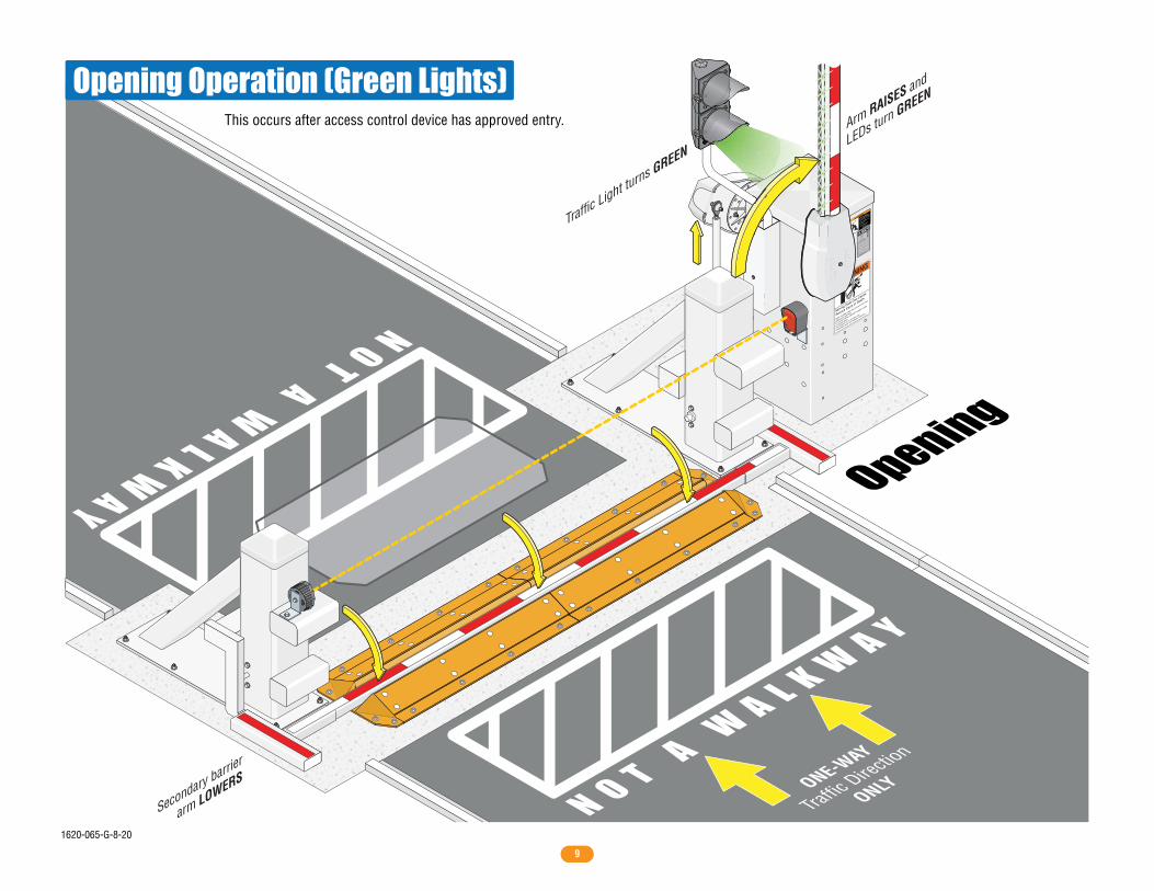
Opening
Traffic Light turns GREEN
Arm RAISES and
LEDs turn GREEN
Secondary barrier
arm LOWERS
Opening Operation (Green Lights)This occurs after access control device has approved entry.
10
1620-065-G-8-20
NOT A WALKWAY
N O T A W A L K W A Y
ONE-WAY
Traffic Direction
ONLY
CLASS
CERTIFIED TO
CAN/CSA C22.2 NO. 247
CONFORMS TO
ANSI/UL-325
VEHICULAR GATE OPERATOR
HP
53382
MODEL
SERIAL
VOLTS
PHASE
AMPS
60 Hz
MAX GATE LOAD
DoorKing, Inc., I
nglewood, CA
MOVING ARM can
cause vehicle damage,
serious injury or d
eath.
STAY CLEAR of arm
at all tim
es.
NO: Pedestrians
Bicycles
Motorcycles
WARNING
Moving Gate Can Cause
Serious Injury or Death
KEEP CLEAR! Gate may move at any tim
e
without prior warning.
Do not let children operate the gate or p
lay
in the gate area.
This entrance is for vehicles only.
Pedestrians must use separate entra
nce.
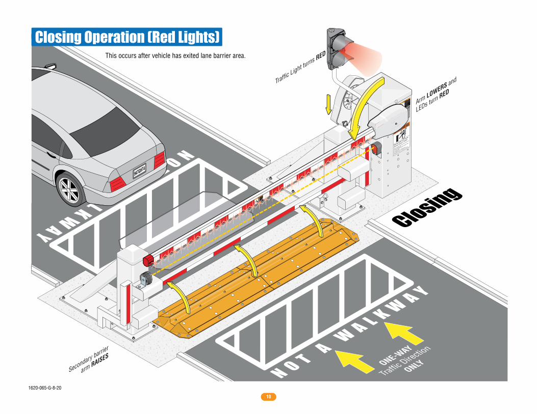
ClosingMOVING ARM can
cause vehicle damage,
serious injury or d
eath.
STAY CLEAR of arm
at all tim
es.
NO: Pedestrians
Bicycles
Motorcycles
WARNING
Traffic Light turns RED
Arm LOWERS and
LEDs turn RED
Secondary barrier
arm RAISES
This occurs after vehicle has exited lane barrier area.
947GHT4
Closing Operation (Red Lights)
11
1620-065-G-8-20
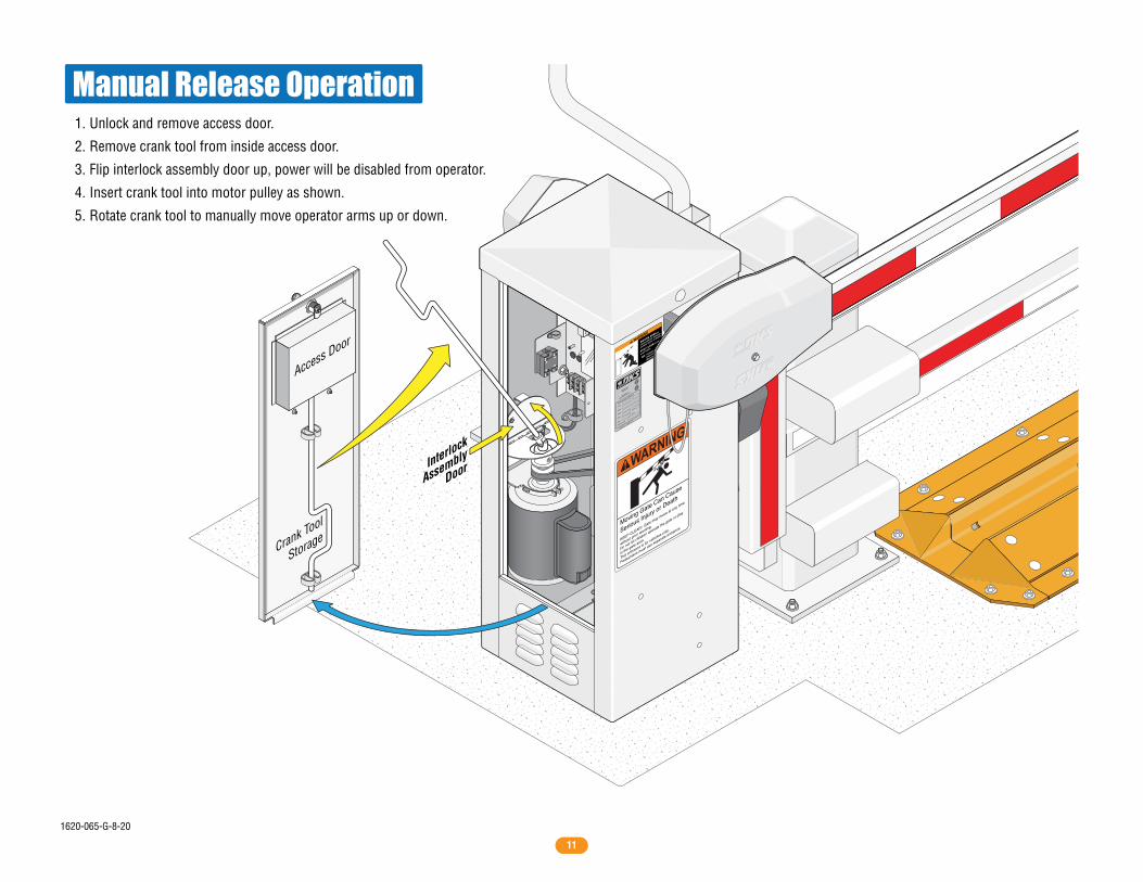
Manual Release Operation
Interlock
Assembly
Door
CLASS
CERTIFIED TO
CAN/CSA C22.2 NO. 247
CONFORMS TO
ANSI/UL-325
VEHICULAR GATE OPERATOR
HP
53382
MODEL
SERIAL
VOLTS
PHASE
AMPS
60 Hz
MAX GATE LOAD
DoorKing, Inc., I
nglewood, CA
MOVING ARM can
cause vehicle damage,
serious injury or d
eath.
STAY CLEAR of arm
at all tim
es.
NO: Pedestrians
Bicycles
Motorcycles
WARNING
Moving Gate Can Cause
Serious Injury or Death
KEEP CLEAR! Gate may move at any tim
e
without prior warning.
Do not let children operate the gate or p
lay
in the gate area.
This entrance is for vehicles only.
Pedestrians must use separate entra
nce.
1
2
4-
3+
Access Door
Crank Tool
Storage
1. Unlock and remove access door.
2. Remove crank tool from inside access door.
3. Flip interlock assembly door up, power will be disabled from operator.
4. Insert crank tool into motor pulley as shown.
5. Rotate crank tool to manually move operator arms up or down.
12
1620-065-G-8-20
S6 AC10-25VDC12-30V
Power Relay
NO NC COM
ChassisGround
Operator Factory Wiring and ALL REQUIRED Components Wiring
Down LimitMagnet(White Dot)
AC Power UP/Auto/Down
115 VAC ConvenienceOpen Outlets
Manual ReleaseAssembly
115 VACNEU HOT
Power
Neutral
Purp
le
Blac
k
Black
Black
Black
Blac
k
Blue
Com
Red
Grou
nd
Up LimitMagnet
REVERSESENSITIVITY
TIMEDELAY
POWER
1 ON2
34
56
78
1 ON2
34
56
78
NC NO
C NC NO
UPLOOP
DOWNLOOP
1 2 3 4 5 6 7 8 9 10 11 12 13 14
1601-010
White
White White
YellowWhite
Orange
Ground
16011/2 HP
115 VACSingle Phase
Motor
InterlockCut-Off Switch
ComN.O.
1601
Access Door
Crank Tool
Storage
Factory/Dealer installed manual release assembly MUST be on the 1601 operator.
MagneticLimit Sensor
12 VDC
Traffic
Light
12 VDC
Reverse/
LED
Octagon
Arm
Terminal 14 - Yellow Reverse Edge
Terminal 9 - Yellow Reverse Edge
NO - Open - GREEN Wire (Green LED)
Black Wire (+)
BlackWire (-)RED Wire (+)
NO - Open - GREEN Wire
NC - Close - ORANGE Wire (Red LED)
NC - Close - RED Wire
C - Common - WHITE Wire
C - Common - WHITE Wire (-)
+ -
Traffic LightTerminal
TrafficLight
Cable
Blac
k
Red/Brown
Gree
n
Red
WhiteWhite
Reve
rse
Inpu
t
24 V
AC -
250
mA
max
Factory/Dealer InstalledManual Release
Type of wiring to be used on ALL external devices:A) Type CL2, CL2P, CL2R, or CL2X. B) Other cable with equivalent or better electrical,mechanical, and flammability ratings.
DoorKing Retro-ReflectivePhotocell (P/N 8080-057)
+-
Reverse Edge/LED Lights Octagon Arm
Arm RelayContacts
WireHarness(1601-345)
Terminal #5 Note:Exceeding 250 mA of power from this terminal may cause the circuit board transformer to overheat, causing intermittent problems.
THIS PRODUCT IS TO BE INSTALLED AND SERVICED BY A TRAINED GATE/DOOR SYSTEMS TECHNICIAN ONLY. Visit www.doorking.com/dealer-locator to find a professional installing and servicing dealer in your area.
Used with 1601 Barrier Gate OperatorWITHOUT Convenience Open
to Enhance Traffic ControlManagement
Use this manual for circuit board 1601-010 Revision W or higher.
Installation Manual 1620 Lane Barrier Add-On1620 Lane Barrier Add-On1620 Lane Barrier Add-On1620 Lane Barrier Add-OnSurface Mount Lane Barrier Accessory
www.doorking.com
DoorKing, Inc.120 S. Glasgow Avenue
Inglewood, California 90301U.S.A.
Phone: 310-645-0023Fax: 310-641-1586
1620-065-G-8-20