Embed Size (px)
Citation preview
Owner’s ManualOwner’s Manual

E-MU 1616/1616m/1212m PCI Digital Audio System
Owner’s Manual© 2006 E-MU Systems
All Rights Reserved
E-MU World Headquarters
E-MU Systems
1500 Green Hills Road
Scotts Valley, CA 95066
USA
Europe
Creative Labs
Ballycoolin Business Park
Blanchardstown
Dublin 15
IRELAND
E-MU Japan
Creative Media K K
Kanda Eight Bldg., 3F
4-6-7 Soto-Kanda
Chiyoda-ku, Tokyo 101-0021
JAPAN
Asia Pacific, Africa, Middle East
Creative Technology Ltd
31 International Business Park
Creative Resource. Singapore 609921
SINGAPORE
Software Version: 2.00
2 Creative Professional
Table of Contents
1- Introduction ................................................................. 9Welcome! ............................................................................................................... 9
All Systems Include: ........................................................................................... 11E-MU 1212M System ......................................................................................... 11E-MU 1616 System ............................................................................................ 11E-MU 1616M System ......................................................................................... 11Sync Daughter Card .......................................................................................... 11PatchMIx DSP .................................................................................................... 12
Notes, Tips and Warnings .............................................................................. 12
2 - Installation ................................................................ 13Setting Up the Digital Audio System...................................................................... 13
Notes for Installation ..................................................................................... 13Safety First! .................................................................................................... 14
Connector Types ............................................................................................... 14Installing the E-MU 1010 PCI Card ........................................................................ 151212M Owners - Install the 0202 Daughter Card .................................................. 16Optional Sync Daughter Card Installation.............................................................. 16Connecting the MicroDock ................................................................................... 17
WARNING: E-MU 0202 & MicroDock .............................................................. 17Software Installation ............................................................................................. 18
Installing the E-MU 1010 PatchMix Software and Drivers ................................ 18Windows XP, Windows XP x64, Windows Vista, Windows Vista x64 .............. 18Uninstalling all Audio Drivers and Applications ............................................... 18Note About Windows Logo Testing ............................................................... 18
3 - PCI Card & Interfaces ................................................. 19The E-MU 1010 PCI Card ...................................................................................... 19
Important ...................................................................................................... 19Connections ..................................................................................................... 19
EDI Connector ............................................................................................... 19S/PDIF Digital Audio Input & Output .............................................................. 19ADAT Optical Digital Input & Output .............................................................. 19
The 0202 Daughter Card...................................................................................... 20Connections ..................................................................................................... 20
Analog Inputs and Outputs ........................................................................... 20MIDI In/Out ................................................................................................... 20
E-MU PCI Digital Audio Systems 3
The MicroDock ..................................................................................................... 21Front Panel Connections ................................................................................... 22
Preamp Section ............................................................................................. 22S/PDIF Digital Audio Input & Output .............................................................. 22ADAT Optical Digital Input & Output .............................................................. 23Headphone Output & Volume Control .......................................................... 23
Rear Panel Connections .................................................................................... 25Line Level Analog Inputs ................................................................................ 25Turntable Inputs & Ground Lug ..................................................................... 25Line Level Analog Outputs ............................................................................. 25Computer Speaker Analog Outputs ................................................................ 26MIDI 1 & 2 In/Outs ........................................................................................ 26EDI Connector (Card) .................................................................................... 26
4 - The PatchMix DSP Mixer ............................................. 29PatchMix DSP ....................................................................................................... 29Overview of the Mixer .......................................................................................... 29
Mixer Window .................................................................................................. 30Mixer Block Diagram ......................................................................................... 30
Pre Fader or Post Fader ................................................................................. 30E-MU Icon in the Windows Taskbar ....................................................................... 31The Toolbar .......................................................................................................... 31The Session .......................................................................................................... 32
New Session ..................................................................................................... 32Open Session .................................................................................................... 33Save Session ..................................................................................................... 33Session Settings ................................................................................................ 33
System Settings .............................................................................................. 33Using External Clock ...................................................................................... 34I/O Settings ................................................................................................... 34
Input Mixer Strips.................................................................................................. 36Input Type ..................................................................................................... 36
Mixer Strip Creation .............................................................................................. 37Multichannel WAVE Files ................................................................................... 38
Windows Media Player/DVD/Surround Sound Playback ................................. 38Insert Section .................................................................................................... 39
Working with Inserts ...................................................................................... 39The Insert Menu ............................................................................................ 40ASIO Direct Monitor Send/Return ................................................................... 41Meter Inserts ................................................................................................. 42
To Set the Input Levels of a Strip ........................................................................ 43Making the Best Possible Recording ............................................................... 43Trim Pot Insert ............................................................................................... 44Test Tone/Signal Generator Insert .................................................................. 45
Managing Your Inserts ...................................................................................... 46Aux Section ....................................................................................................... 47
Sidechain Diagram ........................................................................................ 47Pre or Post Fader Aux Sends .......................................................................... 48
Level, Pan, Solo & Mute Controls ....................................................................... 49Main Section......................................................................................................... 50
TV Screen & Selectors ........................................................................................ 51Effect ............................................................................................................ 51Input ............................................................................................................. 52Output .......................................................................................................... 52
4 Creative Professional
Auxiliary Effects & Returns ................................................................................. 53Sidechain Diagram ........................................................................................ 53
Sync/Sample Rate Indicators .............................................................................. 53Output Section ................................................................................................. 54
Main Inserts ................................................................................................... 54Main Output Fader ........................................................................................ 54Output Level Meters ...................................................................................... 54Monitor Output Level .................................................................................... 54Monitor Balance Control ................................................................................ 54Monitor Output Mute .................................................................................... 54
5 - Effects ....................................................................... 55Overview.............................................................................................................. 55The Effects Palette................................................................................................. 55
FX Insert Chains ................................................................................................ 56The Order of Effects .......................................................................................... 57
Creating, Renaming & Deleting Categories or Presets ..................................... 57Importing and Exporting Core FX Presets and FX Insert Chains ....................... 58
FX Edit Screen ...................................................................................................... 59User Preset Section ............................................................................................ 60Core Effects and Effects Presets ......................................................................... 61
List of Core Effects ................................................................................................ 62DSP Resource Usage ......................................................................................... 62
Core Effects Descriptions....................................................................................... 631-Band Para EQ ................................................................................................ 631-Band Shelf EQ ................................................................................................ 633-Band EQ ........................................................................................................ 644-Band EQ ........................................................................................................ 65Auto-Wah ......................................................................................................... 66Chorus .............................................................................................................. 67Compressor ...................................................................................................... 67
Basic Controls ................................................................................................ 68Distortion .......................................................................................................... 69Flanger ............................................................................................................. 70Freq Shifter ....................................................................................................... 71Leveling Amp .................................................................................................... 72Lite Reverb ........................................................................................................ 73Mono Delays - 100, 250, 500, 750, 1500, 3000 ................................................ 74Phase Shifter ..................................................................................................... 75Rotary ............................................................................................................... 75Speaker Simulator ............................................................................................. 76Stereo Delays - 100, 250, 500, 750, 1500 ......................................................... 77Vocal Morpher .................................................................................................. 79Gate ................................................................................................................. 80
Applications ................................................................................................... 80Parameters .................................................................................................... 81Threshold ...................................................................................................... 81Release Time ................................................................................................. 81Max Gain Reduction ...................................................................................... 81Lookahead .................................................................................................... 81Level Meter ................................................................................................... 82Gain Reduction Meter .................................................................................... 82
Reshaper .......................................................................................................... 83Applications ................................................................................................... 83
E-MU PCI Digital Audio Systems 5
Multimode EQ .................................................................................................. 86Applications ................................................................................................... 86Parameters .................................................................................................... 87Lowpass ........................................................................................................ 87Highpass ....................................................................................................... 87Highpass -> Lowpass ..................................................................................... 88Highpass || Lowpass ...................................................................................... 88Band Pass ...................................................................................................... 89Band Cut ....................................................................................................... 89
RFX Compressor ................................................................................................ 90Signal Flow ................................................................................................... 90Parameters .................................................................................................... 91Threshold ...................................................................................................... 91Gain Reduction Meter .................................................................................... 91Ratio ............................................................................................................. 91Attack ............................................................................................................ 91Release .......................................................................................................... 91Gain .............................................................................................................. 92Advanced Parameters .................................................................................... 92Soft Knee ....................................................................................................... 92Gate .............................................................................................................. 94Comp Lookahead/Delay ................................................................................ 94Auto-Release .................................................................................................. 95Max Compression .......................................................................................... 96Neg Compression .......................................................................................... 96Input Mode ................................................................................................... 97Example Settings ........................................................................................... 98Multimode EQ Settings ................................................................................ 100Compressor Settings .................................................................................... 100
E-MU PowerFX.................................................................................................... 101Automating E-MU PowerFX ............................................................................. 103E-MU PowerFX Resource Availability ................................................................ 103
Rendering Audio with E-MU PowerFX ................................................................. 105General Tips for Rendering using PowerFX .................................................. 105Tips for using Freeze Mode on Cubase LE .................................................... 105
Using E-MU PowerFX with WaveLab and SoundForge ..................................... 105E-MU VST E-Wire................................................................................................. 106
E-Delay Compensator ...................................................................................... 107E-Delay Compensator Use ............................................................................ 108E-Delay Units Parameter .............................................................................. 109Grouping Tracks .......................................................................................... 109
6 - Appendix ................................................................. 111Using High Sample Rates .................................................................................... 111
Overview ........................................................................................................ 111WDM Recording and Playback Behavior .......................................................... 113
Sync Daughter Card Supplement ........................................................................ 114SMPTE Conversion .......................................................................................... 114SMPTE Options ............................................................................................... 114SMPTE Modes of Operation ............................................................................. 115
Host Mode .................................................................................................. 115External Mode ............................................................................................. 115Flywheel Mode ............................................................................................ 115Flywheel Modes .......................................................................................... 115Stripe Mode ................................................................................................. 116
6 Creative Professional
Example SMPTE Connection ............................................................................ 116MIDI Time Code (MTC) ........................................................................................ 117Word Clock In/Out ............................................................................................. 117Getting in Sync................................................................................................... 119Useful Information.............................................................................................. 120
Cables - balanced or unbalanced? ................................................................... 120Balanced Cables .......................................................................................... 120Unbalanced Cables ...................................................................................... 120
Adapter Cables ............................................................................................... 1211/8” Mini-phone to 1/4” Adapters ................................................................ 121Cinch (RCA) to 1/4” Adapters ....................................................................... 121
Digital Cables .................................................................................................. 121AES/EBU to S/PDIF Cable Adapter ................................................................... 121Grounding ...................................................................................................... 122Phantom Power .............................................................................................. 122Appearance Settings in Windows .................................................................... 122
Technical Specifications....................................................................................... 123Internet References............................................................................................. 134
Forums ........................................................................................................ 134
Index ............................................................................ 137
E-MU PCI Digital Audio Systems 7

8 Creative Professional
1- IntroductionWelcome!
1- Introduction
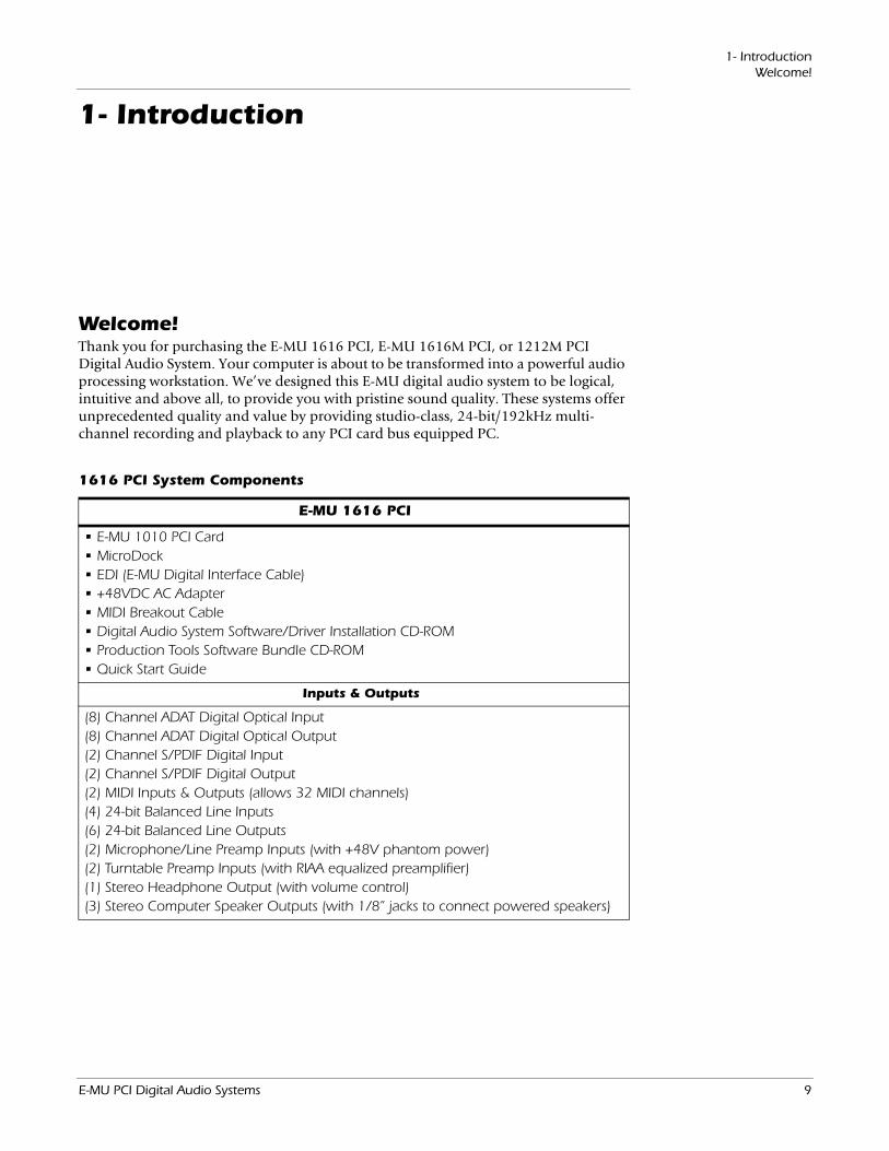
Welcome!Thank you for purchasing the E-MU 1616 PCI, E-MU 1616M PCI, or 1212M PCI Digital Audio System. Your computer is about to be transformed into a powerful audio processing workstation. We’ve designed this E-MU digital audio system to be logical, intuitive and above all, to provide you with pristine sound quality. These systems offer unprecedented quality and value by providing studio-class, 24-bit/192kHz multi-channel recording and playback to any PCI card bus equipped PC.
1616 PCI System Components
E-MU 1616 PCI
• E-MU 1010 PCI Card• MicroDock• EDI (E-MU Digital Interface Cable)• +48VDC AC Adapter• MIDI Breakout Cable• Digital Audio System Software/Driver Installation CD-ROM• Production Tools Software Bundle CD-ROM• Quick Start Guide
Inputs & Outputs
(8) Channel ADAT Digital Optical Input(8) Channel ADAT Digital Optical Output(2) Channel S/PDIF Digital Input(2) Channel S/PDIF Digital Output(2) MIDI Inputs & Outputs (allows 32 MIDI channels)(4) 24-bit Balanced Line Inputs(6) 24-bit Balanced Line Outputs(2) Microphone/Line Preamp Inputs (with +48V phantom power)(2) Turntable Preamp Inputs (with RIAA equalized preamplifier)(1) Stereo Headphone Output (with volume control)(3) Stereo Computer Speaker Outputs (with 1/8” jacks to connect powered speakers)
E-MU PCI Digital Audio Systems 9
1- IntroductionWelcome!
1616M PCI System Components
E-MU 1616M PCI
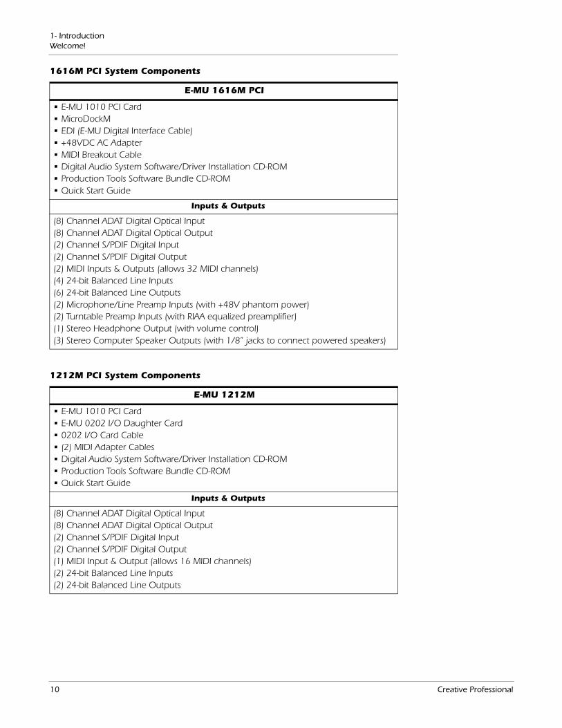
• E-MU 1010 PCI Card• MicroDockM• EDI (E-MU Digital Interface Cable)• +48VDC AC Adapter• MIDI Breakout Cable• Digital Audio System Software/Driver Installation CD-ROM• Production Tools Software Bundle CD-ROM• Quick Start Guide
Inputs & Outputs
(8) Channel ADAT Digital Optical Input(8) Channel ADAT Digital Optical Output(2) Channel S/PDIF Digital Input(2) Channel S/PDIF Digital Output(2) MIDI Inputs & Outputs (allows 32 MIDI channels)(4) 24-bit Balanced Line Inputs(6) 24-bit Balanced Line Outputs(2) Microphone/Line Preamp Inputs (with +48V phantom power)(2) Turntable Preamp Inputs (with RIAA equalized preamplifier)(1) Stereo Headphone Output (with volume control)(3) Stereo Computer Speaker Outputs (with 1/8” jacks to connect powered speakers)
1212M PCI System Components
E-MU 1212M
• E-MU 1010 PCI Card• E-MU 0202 I/O Daughter Card• 0202 I/O Card Cable• (2) MIDI Adapter Cables• Digital Audio System Software/Driver Installation CD-ROM• Production Tools Software Bundle CD-ROM• Quick Start Guide
Inputs & Outputs
(8) Channel ADAT Digital Optical Input(8) Channel ADAT Digital Optical Output(2) Channel S/PDIF Digital Input(2) Channel S/PDIF Digital Output(1) MIDI Input & Output (allows 16 MIDI channels)(2) 24-bit Balanced Line Inputs(2) 24-bit Balanced Line Outputs
10 Creative Professional
1- IntroductionWelcome!
All Systems Include:The E-MU 1010 PCI Card is the heart of all three systems. Its powerful hardware DSP processor allows you to use over 16 simultaneous hardware-based effects, which place minimal load on your computer’s CPU. The E-MU 1010 PCI Card also provides eight-channels of ADAT® optical digital input and output, as well as a S/PDIF stereo digital input and output.
The PatchMix DSP mixer application is included in all the systems. PatchMix DSP delivers unmatched flexibility in routing your audio between physical inputs and outputs, virtual (ASIO/WAVE) inputs and outputs and internal hardware effects and buses—no external mixer needed. You can add digital effects, EQs, meters, level controls and ASIO/WAVE sends anywhere you like in the signal chain.
Because the effects and mixing are hardware-based, there is no latency when you record. You can even record a dry signal while monitoring yourself with effects! Mixer setups can be saved and instantly recalled for specific purposes such as recording, mixdown, jamming, special effect setups, playing games, watching DVDs, or general computer use.
E-MU 1212M SystemThe E-MU 1212M includes the 0202 Daughter Card, which provides 2 line level, balanced analog inputs, 2 line level, balanced analog outputs, plus MIDI input and output. This is no-compromise audio interface, using ultra-high performance 24-bit/192kHz A/D - D/A converters to deliver an unbelievable 120dB dynamic range.
E-MU 1616 System Note: The digital I/O
on the 1010 PCI card are not used when you have the MicroDock.
The E-MU 1616 includes the MicroDock, which is a half rack-space, audio interface. The MicroDock adds the following input and output capabilities to the system: two mic/line inputs with custom low-noise preamps, 4 balanced line level analog inputs, an RIAA stereo turntable preamp, 6 balanced line level outputs, an assignable headphone output, two sets of MIDI I/O ports, an additional S/PDIF optical output, and four stereo mini phone jacks for easy connection to powered speaker systems. Of course, professional-quality, 24-bit A/D and D/A converters with automatic DC blocking are used throughout.
E-MU 1616M System The E-MU 1616M system includes the MicroDockM, a no compromise, mastering-grade system, which includes all the features of the 1616 system. The 1616M system is distinguished by the addition of ultra-high performance 24-bit/192kHz A/D - D/A converters which deliver an incredible 120dB of dynamic range.
Sync Daughter CardThe Sync Daughter Card can be purchased as an optional upgrade for the 1616M, 1616 MicroDock and 1212M systems. The Sync Card adds Word Clock in and out for sample-synchronizing outboard digital equipment and SMPTE longitudinal time code in/out for syncing other recording equipment. A separate MIDI Time Code output port on the Sync Card eliminates timing problems caused by combining MTC with MIDI performance data.
You’ll want to keep up with the latest software and options for your E-MU digital audio system. You can find all of this, plus other helpful information, at the E-MU Website: http://www.emu.com.
E-MU PCI Digital Audio Systems 11
1- IntroductionWelcome!
PatchMIx DSPPatchMix DSP offers unmatched flexibility in routing your audio between physical inputs/outputs, virtual (ASIO/WAVE) inputs/outputs, internal hardware effects and buses. No external mixer is needed. You can add digital effects, EQs, meters, level controls and ASIO/WAVE sends anywhere you like in the signal chain.
Because the effects and mixing are hardware-based, you can record using effects with near zero-latency. You can even record a dry signal while monitoring yourself with effects! Mixer setups can be saved and instantly recalled for specific purposes such as recording, mixdown, jamming, special effect setups, playing games, watching DVDs, or general computer use.
You’ll want to keep up with the latest software and options for your E-MU digital audio system. You can find all of this, plus other helpful information, at the E-MU Website: http://www.emu.com.
Notes, Tips and WarningsItems of special interest are presented in this document as notes, tips and warnings.
Notes provide additional information related to the topic being discussed. Often, notes describe the interaction between the topic and some other aspect of the system.
Tips describe applications for the topic under discussion.
Warnings are especially important, since they help you avoid activities that can cause damage to your files, your computer or yourself.
12 Creative Professional
2 - InstallationSetting Up the Digital Audio System
2 - Installation
Setting Up the Digital Audio SystemThere are six basic steps to installing your E-MU system:
1. Remove any other sound cards you have in your computer. (Once you are sure that the E-MU card works properly, your old sound card can be reinstalled if desired.)
2. Install the E-MU 1010 PCI card in your computer. Go there.
3. Install the 0202 Daughter Card or Sync Daughter Card (if applicable). Go there.
4. Connect the MicroDock (if applicable).
5. Install the PatchMix DSP software onto your computer.
6. Connect audio, MIDI and synchronization cables between the E-MU system and your other gear.
7. After Software Installation, click on the E-MU icon in the Windows SysTray to open PatchMix DSP, then click the ? in the upper right corner to open the complete operation manual.
Notes for Installation
• IF AT ANY TIME DURING THIS INSTALLATION YOU SEE NO RESPONSE: Use the Alt-Tab feature to select other applications. One of them may be the Microsoft Digital Signature warning. It is possible for this warning to appear behind the installation screen.
• Make sure you have the latest Windows Service Packs from Microsoft (Windows XP - SP 2 or higher).
• Disable onboard sound and uninstall all other sound cards. (If you wish to try using multiple sound cards in your system, do so after you have confirmed that your E-MU Digital Audio System is operating normally.)
• InstallShield “IKernel Application Error” on Windows XP: When installing this software on Windows XP, you may be confronted with a “kernel error” at the very end of installation. This is an issue with the InstallShield program, which is what we use to install software on your computer. Please do not be alarmed by this, as the error is innocuous.
To read more about this error, and obtain instructions on how to avoid getting the message, please visit this website: http://support.installshield.com/kb/view.asp?articleid=q108020
• Multiple Digital Audio System sound cards are not supported.
E-MU PCI Digital Audio Systems 13
2 - InstallationSetting Up the Digital Audio System
• To avoid possible permanent damage to your hardware, make sure that all connec-tions are made with the host computer’s power off. Unplug the computer’s power cable to make sure that the computer is not in sleep mode.
• Take care to avoid static damage to any components of your system. Internal computer surfaces, the E-MU 1010 PCI board and the interfaces are susceptible to electrostatic discharge, commonly known as “static.” Electrostatic discharge can damage or destroy electronic devices. Here are some procedures you can follow when handling electronic devices in order to minimize the possibility of causing electrostatic damage:
• Avoid any unnecessary movement, such as scuffing your feet when handling electronic devices, since most movement can generate additional charges of static electricity.
• Minimize the handling of the PCI card. Keep it in its static-free package until needed. Transport or store the board only in its protective package.
• When handling a PCI card, avoid touching its connector pins. Try to handle the board by its edges only.
• Before installing a PCI card into your computer, you should be grounded. Use a ground strap to discharge any static electric charge built up on your body. The ground strap attaches to your wrist and any unpainted metal surface within your computer. If you don’t have a ground strap, you can ground yourself by touching the metal case of another piece of grounded equipment.
Please read the following sections as they apply to your system as you install the E-MU 1010, paying special attention to the various warnings they include.
Prior to installing the hardware, take a few moments to write down the 18-digit serial number, which is located on the back of the box and on the 1010 PCI Card. This number can help EMU Customer Service troubleshoot any problems you may encounter—by writing the number down now, you’ll avoid having to open your computer to find it later on.
Safety First! As you install hardware components, observe the following general precautions to avoid damage to your equipment and yourself.
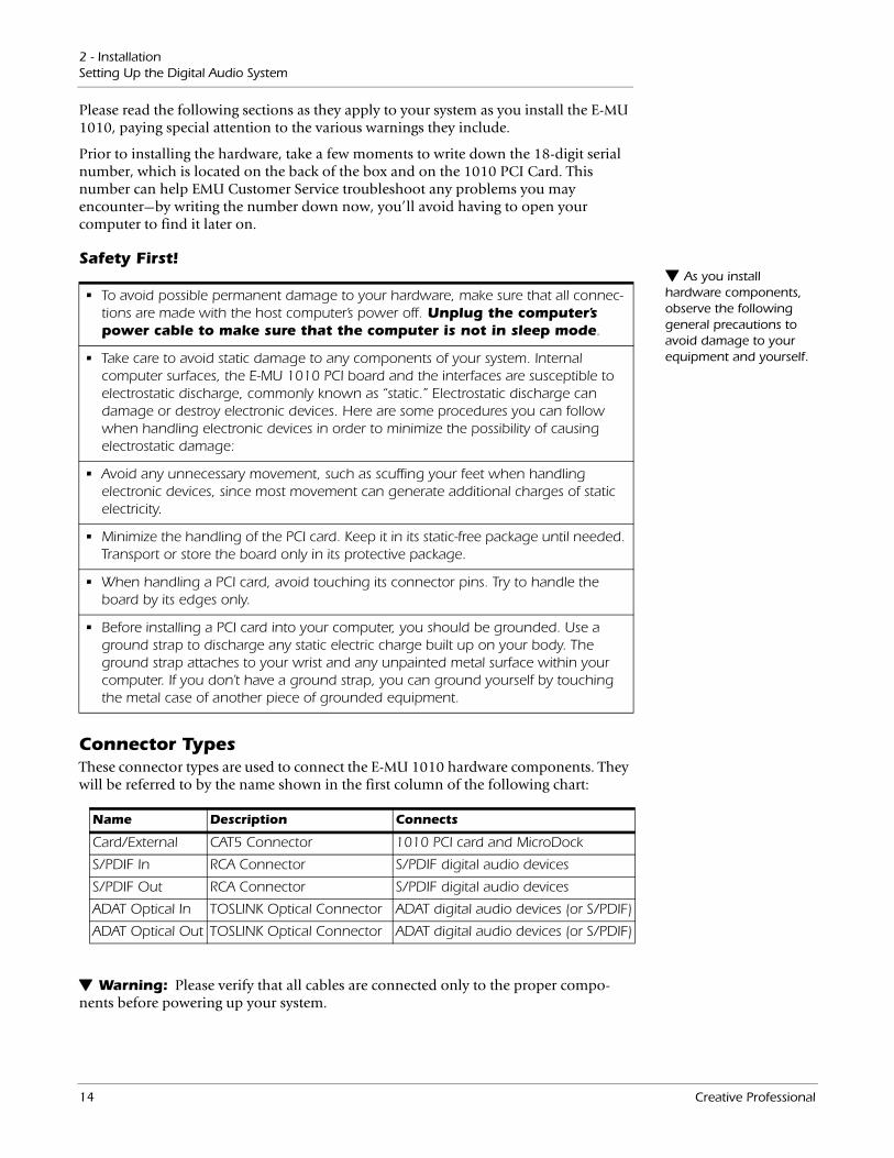
Connector TypesThese connector types are used to connect the E-MU 1010 hardware components. They will be referred to by the name shown in the first column of the following chart:
Name Description Connects
Card/External CAT5 Connector 1010 PCI card and MicroDock
S/PDIF In RCA Connector S/PDIF digital audio devices
S/PDIF Out RCA Connector S/PDIF digital audio devices
ADAT Optical In TOSLINK Optical Connector ADAT digital audio devices (or S/PDIF)
ADAT Optical Out TOSLINK Optical Connector ADAT digital audio devices (or S/PDIF)
Warning: Please verify that all cables are connected only to the proper compo-nents before powering up your system.
14 Creative Professional
2 - InstallationInstalling the E-MU 1010 PCI Card
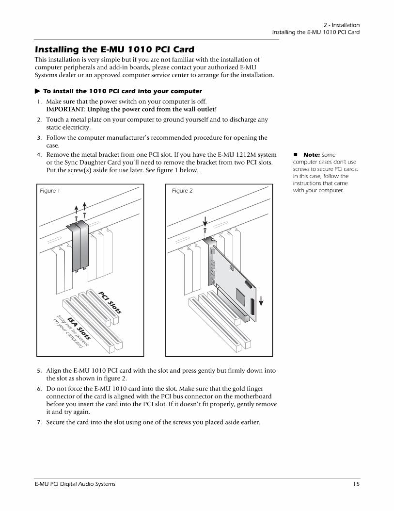
Installing the E-MU 1010 PCI CardThis installation is very simple but if you are not familiar with the installation of computer peripherals and add-in boards, please contact your authorized E-MU Systems dealer or an approved computer service center to arrange for the installation.
To install the 1010 PCI card into your computer
PCI Slots
ISA Slots
(may not be present
on your computer)
Figure 1 Figure 2
1. Make sure that the power switch on your computer is off. IMPORTANT: Unplug the power cord from the wall outlet!
2. Touch a metal plate on your computer to ground yourself and to discharge any static electricity.
3. Follow the computer manufacturer’s recommended procedure for opening the case.
Note: Some computer cases don’t use screws to secure PCI cards. In this case, follow the instructions that came with your computer.
4. Remove the metal bracket from one PCI slot. If you have the E-MU 1212M system or the Sync Daughter Card you’ll need to remove the bracket from two PCI slots. Put the screw(s) aside for use later. See figure 1 below.
5. Align the E-MU 1010 PCI card with the slot and press gently but firmly down into the slot as shown in figure 2.
6. Do not force the E-MU 1010 card into the slot. Make sure that the gold finger connector of the card is aligned with the PCI bus connector on the motherboard before you insert the card into the PCI slot. If it doesn’t fit properly, gently remove it and try again.
7. Secure the card into the slot using one of the screws you placed aside earlier.
E-MU PCI Digital Audio Systems 15
2 - Installation1212M Owners - Install the 0202 Daughter Card
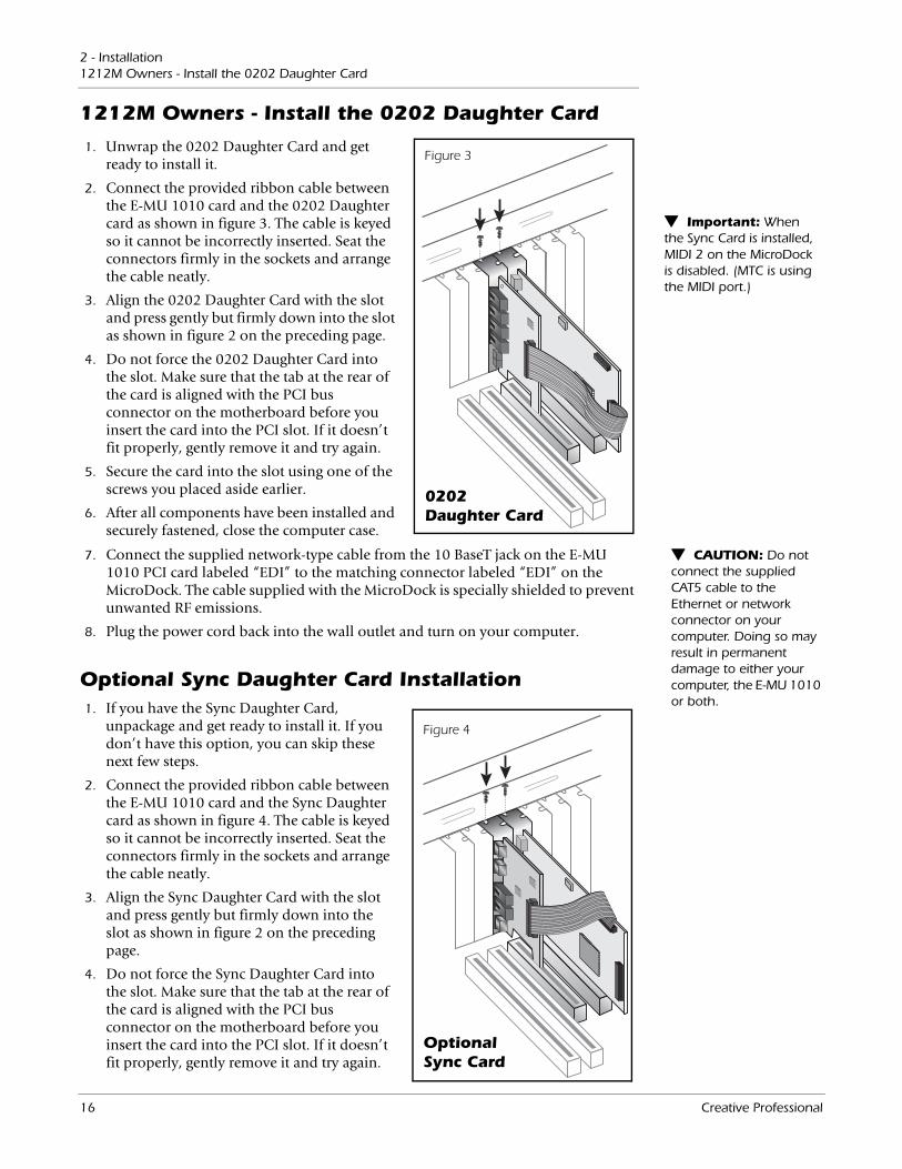
1212M Owners - Install the 0202 Daughter Card
Important: When the Sync Card is installed, MIDI 2 on the MicroDock is disabled. (MTC is using the MIDI port.)
Figure 3
0202 Daughter Card
1. Unwrap the 0202 Daughter Card and get ready to install it.
2. Connect the provided ribbon cable between the E-MU 1010 card and the 0202 Daughter card as shown in figure 3. The cable is keyed so it cannot be incorrectly inserted. Seat the connectors firmly in the sockets and arrange the cable neatly.
3. Align the 0202 Daughter Card with the slot and press gently but firmly down into the slot as shown in figure 2 on the preceding page.
4. Do not force the 0202 Daughter Card into the slot. Make sure that the tab at the rear of the card is aligned with the PCI bus connector on the motherboard before you insert the card into the PCI slot. If it doesn’t fit properly, gently remove it and try again.
5. Secure the card into the slot using one of the screws you placed aside earlier.
6. After all components have been installed and securely fastened, close the computer case.
CAUTION: Do not connect the supplied CAT5 cable to the Ethernet or network connector on your computer. Doing so may result in permanent damage to either your computer, the E-MU 1010 or both.
7. Connect the supplied network-type cable from the 10 BaseT jack on the E-MU 1010 PCI card labeled “EDI” to the matching connector labeled “EDI” on the MicroDock. The cable supplied with the MicroDock is specially shielded to prevent unwanted RF emissions.
8. Plug the power cord back into the wall outlet and turn on your computer.
Optional Sync Daughter Card Installation1. If you have the Sync Daughter Card,
unpackage and get ready to install it. If you don’t have this option, you can skip these next few steps.
2. Connect the provided ribbon cable between the E-MU 1010 card and the Sync Daughter card as shown in figure 4. The cable is keyed so it cannot be incorrectly inserted. Seat the connectors firmly in the sockets and arrange the cable neatly.
3. Align the Sync Daughter Card with the slot and press gently but firmly down into the slot as shown in figure 2 on the preceding page.
4. Do not force the Sync Daughter Card into the slot. Make sure that the tab at the rear of the card is aligned with the PCI bus connector on the motherboard before you insert the card into the PCI slot. If it doesn’t fit properly, gently remove it and try again.
Optional Sync Card
Figure 4
16 Creative Professional
2 - InstallationConnecting the MicroDock
5. Secure the card into the slot using one of the screws you placed aside earlier.
6. After all components have been installed and securely fastened, close the computer case.
7. Plug the power cord back into the wall outlet and turn on your computer.
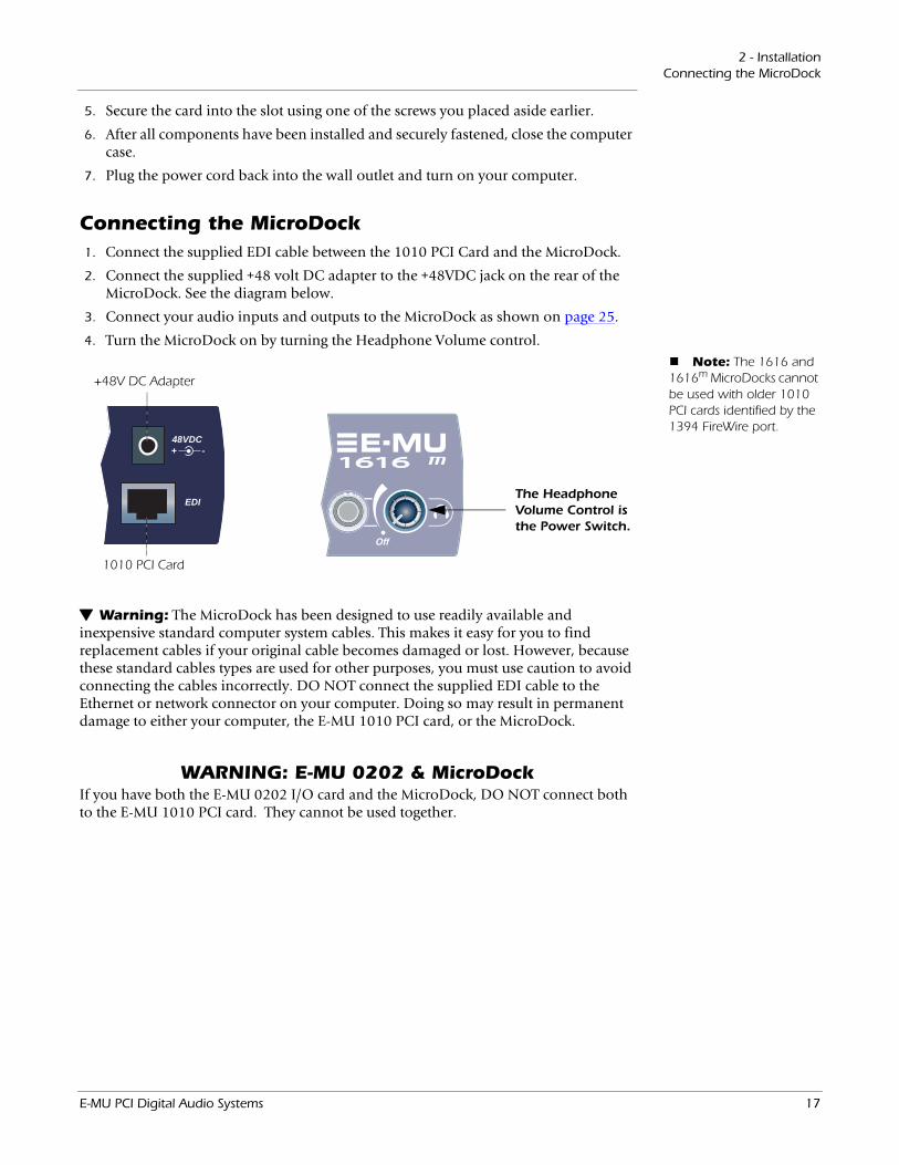
Connecting the MicroDock
EDI
48 VDC+ -
The Headphone Volume Control is the Power Switch.
+48V DC Adapter
1010 PCI Card
1. Connect the supplied EDI cable between the 1010 PCI Card and the MicroDock.
2. Connect the supplied +48 volt DC adapter to the +48VDC jack on the rear of the MicroDock. See the diagram below.
3. Connect your audio inputs and outputs to the MicroDock as shown on page 25.
4. Turn the MicroDock on by turning the Headphone Volume control. Note: The 1616 and
1616m MicroDocks cannot be used with older 1010 PCI cards identified by the 1394 FireWire port.
Warning: The MicroDock has been designed to use readily available and inexpensive standard computer system cables. This makes it easy for you to find replacement cables if your original cable becomes damaged or lost. However, because these standard cables types are used for other purposes, you must use caution to avoid connecting the cables incorrectly. DO NOT connect the supplied EDI cable to the Ethernet or network connector on your computer. Doing so may result in permanent damage to either your computer, the E-MU 1010 PCI card, or the MicroDock.
WARNING: E-MU 0202 & MicroDockIf you have both the E-MU 0202 I/O card and the MicroDock, DO NOT connect both to the E-MU 1010 PCI card. They cannot be used together.
E-MU PCI Digital Audio Systems 17
2 - InstallationSoftware Installation
Software InstallationInstalling the E-MU 1010 PatchMix Software and DriversThe first time you restart your PC after installing the E-MU 1010 PCI card, you will need to install the PatchMix DSP software and E-MU 1010 PCI card drivers.
Windows XP, Windows XP x64, Windows Vista, Windows Vista x64The software is not compatible with other versions of Windows.
Serial Number - During the registration process, you will be asked to enter your 18-digit serial number. The serial number is located on the back of the box and on the 1010 PCI Card.
1. After you have installed your Digital Audio System, turn on your computer. Windows automatically detects the Digital Audio System and searches for device drivers.
2. When prompted for the audio drivers, click the Cancel button.
3. Insert the E-MU software Installation CD into your CD-ROM drive. If Windows AutoPlay mode is enabled for your CD-ROM drive, the CD starts running automat-ically. If not, from your Windows desktop, click Start->Run and type d:\setup.exe (replace d:\ with the drive letter of your CD-ROM drive). You can also open the CD and double-click Setup.exe.
4. The installation splash screen appears. Follow the instructions on the screen to complete the installation.
5. Choose “Continue Anyway” when you encounter the “Windows Logo Testing” warning screen. See the note below for more information.
6. When prompted, restart your computer.
Uninstalling all Audio Drivers and Applications At times you may need to uninstall or reinstall some or all of the audio card's applica-tions and device drivers to correct problems, change configurations, or upgrade outdated drivers or applications. Before you begin, close all audio card applications. Applications still running during the uninstallation will not be removed.
1. Click Start -> Settings -> Control Panel.
2. Double-click the Add/Remove Programs icon.
3. Click the Install/Uninstall tab (or Change or Remove Programs button).
4. Select the E-MU driver/application entries and then click the Add/Remove (or Change/Remove) button.
5. In the InstallShield Wizard dialog box, select the Remove option.
6. Click the Yes button. Restart your computer when prompted.
7. You may now re-install existing or updated E-MU 1010 PCI card device drivers or applications.
Note About Windows Logo TestingWhen you install the 1616 PCI drivers, you will see a dialog box informing you either that the driver has not been certified by Windows Hardware Quality Labs (WHQL), or that the driver is signed by Creative Labs, Inc, and you will be asked if you would like to continue with the installation.
The 1616 PCI audio drivers are not certified by WHQL because the product does not support some of the features that the Microsoft Windows Logo Program requires, most notably Universal Audio Architecture (UAA) and Digital Rights Management (DRM).
Despite this, the 1616 PCI audio drivers have been rigorously tested using the same test procedures that a WHQL qualified driver requires, and it passes in all of the other important categories, including those that measure the relative stability of the driver. So, it is perfectly safe to install these drivers on your computer.
18 Creative Professional
3 - PCI Card & InterfacesThe E-MU 1010 PCI Card
3 - PCI Card & Interfaces
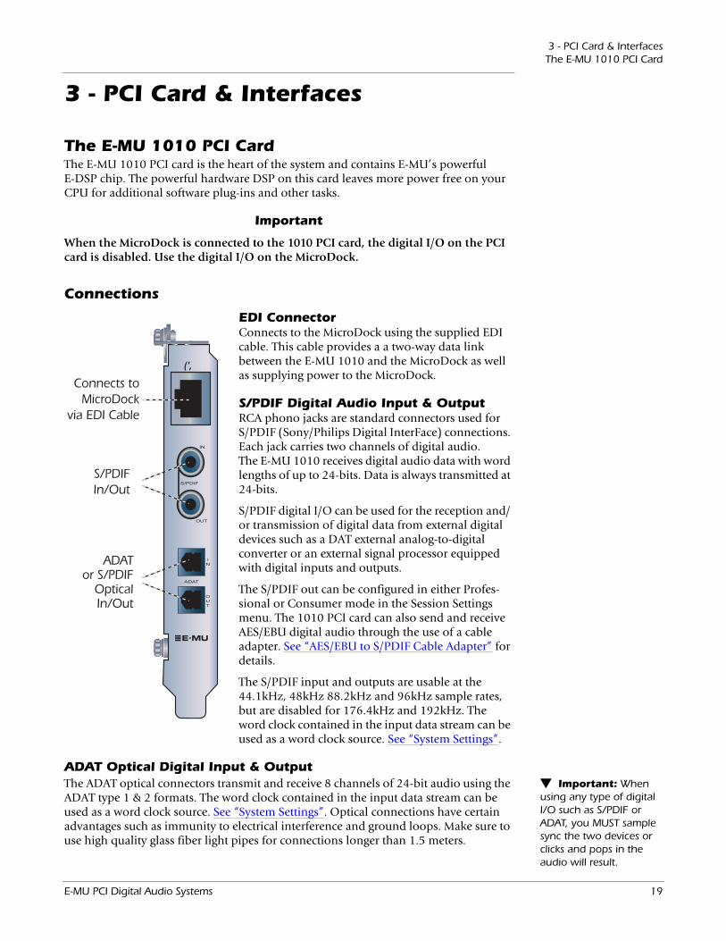
The E-MU 1010 PCI CardThe E-MU 1010 PCI card is the heart of the system and contains E-MU’s powerful E-DSP chip. The powerful hardware DSP on this card leaves more power free on your CPU for additional software plug-ins and other tasks.
Important
When the MicroDock is connected to the 1010 PCI card, the digital I/O on the PCI card is disabled. Use the digital I/O on the MicroDock.
Connections
EDI ConnectorConnects to the MicroDock using the supplied EDI cable. This cable provides a a two-way data link between the E-MU 1010 and the MicroDock as well as supplying power to the MicroDock.
S/PDIF Digital Audio Input & OutputRCA phono jacks are standard connectors used for S/PDIF (Sony/Philips Digital InterFace) connections. Each jack carries two channels of digital audio. The E-MU 1010 receives digital audio data with word lengths of up to 24-bits. Data is always transmitted at 24-bits.
S/PDIF digital I/O can be used for the reception and/ or transmission of digital data from external digital devices such as a DAT external analog-to-digital converter or an external signal processor equipped with digital inputs and outputs.
The S/PDIF out can be configured in either Profes-sional or Consumer mode in the Session Settings menu. The 1010 PCI card can also send and receive AES/EBU digital audio through the use of a cable adapter. See “AES/EBU to S/PDIF Cable Adapter” for details.
The S/PDIF input and outputs are usable at the 44.1kHz, 48kHz 88.2kHz and 96kHz sample rates, but are disabled for 176.4kHz and 192kHz. The word clock contained in the input data stream can be used as a word clock source. See “System Settings”.
ADAT Optical Digital Input & Output Important: When using any type of digital I/O such as S/PDIF or ADAT, you MUST sample sync the two devices or clicks and pops in the audio will result.
The ADAT optical connectors transmit and receive 8 channels of 24-bit audio using the ADAT type 1 & 2 formats. The word clock contained in the input data stream can be used as a word clock source. See “System Settings”. Optical connections have certain advantages such as immunity to electrical interference and ground loops. Make sure to use high quality glass fiber light pipes for connections longer than 1.5 meters.
(',
Connects toMicroDock
via EDI Cable
S/PDIFIn/Out
ADATor S/PDIF
OpticalIn/Out
E-MU PCI Digital Audio Systems 19
3 - PCI Card & InterfacesThe 0202 Daughter Card
At the 96kHz or 192kHz sample rates, the industry standard S/MUX interleaving scheme is used for ADAT input and output. S/MUX uses additional ADAT channels to achieve the required bandwidth. See the chart below or go here for additional infor-mation.
Sample Rate Number of Audio Channels
44kHz/48kHz 8 channels of 24-bit audio88.2kHz/96kHz 4 channels of 24-bit audio, using S/MUX standard176.4kHz/192kHz
2 channels of 24-bit audio, using S/MUX standard
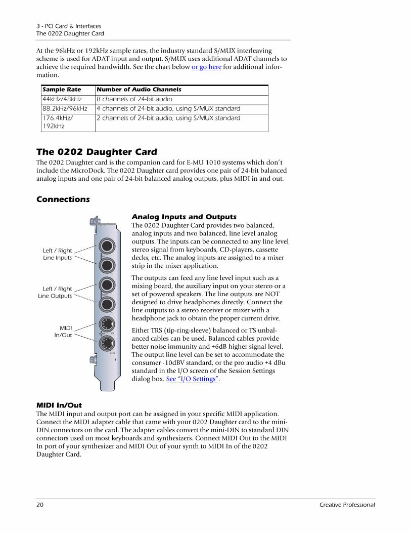
The 0202 Daughter CardThe 0202 Daughter card is the companion card for E-MU 1010 systems which don’t include the MicroDock. The 0202 Daughter card provides one pair of 24-bit balanced analog inputs and one pair of 24-bit balanced analog outputs, plus MIDI in and out.
Connections
Analog Inputs and OutputsThe 0202 Daughter Card provides two balanced, analog inputs and two balanced, line level analog outputs. The inputs can be connected to any line level stereo signal from keyboards, CD-players, cassette decks, etc. The analog inputs are assigned to a mixer strip in the mixer application.
The outputs can feed any line level input such as a mixing board, the auxiliary input on your stereo or a set of powered speakers. The line outputs are NOT designed to drive headphones directly. Connect the line outputs to a stereo receiver or mixer with a headphone jack to obtain the proper current drive.
Either TRS (tip-ring-sleeve) balanced or TS unbal-anced cables can be used. Balanced cables provide better noise immunity and +6dB higher signal level. The output line level can be set to accommodate the consumer -10dBV standard, or the pro audio +4 dBu standard in the I/O screen of the Session Settings dialog box. See “I/O Settings”.
MIDI In/OutThe MIDI input and output port can be assigned in your specific MIDI application. Connect the MIDI adapter cable that came with your 0202 Daughter card to the mini-DIN connectors on the card. The adapter cables convert the mini-DIN to standard DIN connectors used on most keyboards and synthesizers. Connect MIDI Out to the MIDI In port of your synthesizer and MIDI Out of your synth to MIDI In of the 0202 Daughter Card.
Left / RightLine Inputs
Left / RightLine Outputs
MIDIIn/Out
20 Creative Professional
3 - PCI Card & InterfacesThe MicroDock
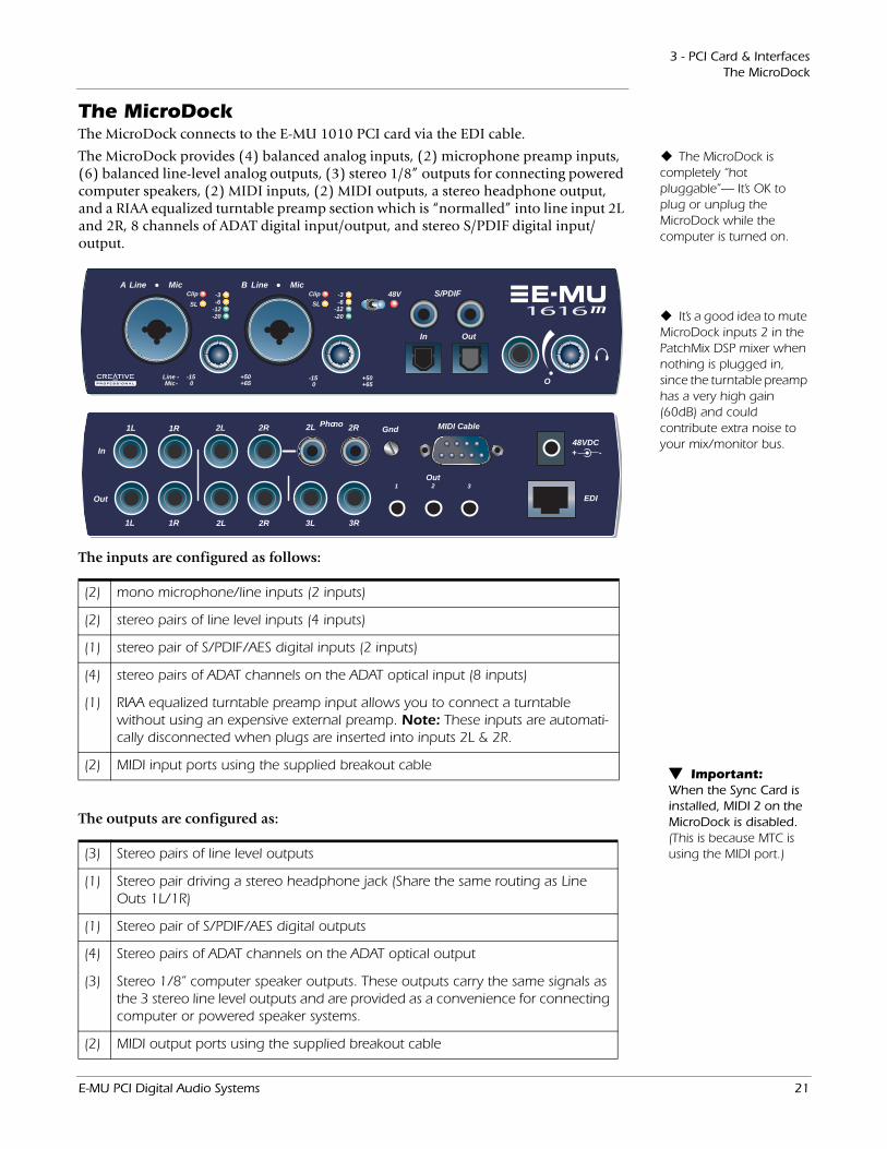
The MicroDockThe MicroDock connects to the E-MU 1010 PCI card via the EDI cable.
LineA Mic
-15 0
Line -Mic -
Clip
+50
LineB Mic
+65-15 0
48V
+50+65
S/PDIF
In Out
-3-6
-12-20
SL
Clip -3-6
-12-20
SL
O
EDI
In
1L 1R 2L 2R
3L 3R2L 2R
Out
1L 1R
PhonoGnd2L 2R
1 2Out
48 VDC+ -
MIDI Cable
3
(2) mono microphone/line inputs (2 inputs)
(2) stereo pairs of line level inputs (4 inputs)
(1) stereo pair of S/PDIF/AES digital inputs (2 inputs)
(4) stereo pairs of ADAT channels on the ADAT optical input (8 inputs)
(1) RIAA equalized turntable preamp input allows you to connect a turntable without using an expensive external preamp. Note: These inputs are automati-cally disconnected when plugs are inserted into inputs 2L & 2R.
(2) MIDI input ports using the supplied breakout cable
(3) Stereo pairs of line level outputs
(1) Stereo pair driving a stereo headphone jack (Share the same routing as Line Outs 1L/1R)
(1) Stereo pair of S/PDIF/AES digital outputs
(4) Stereo pairs of ADAT channels on the ADAT optical output
(3) Stereo 1/8” computer speaker outputs. These outputs carry the same signals as the 3 stereo line level outputs and are provided as a convenience for connecting computer or powered speaker systems.
(2) MIDI output ports using the supplied breakout cable
The MicroDock is completely “hot pluggable”— It’s OK to plug or unplug the MicroDock while the computer is turned on.
It’s a good idea to mute MicroDock inputs 2 in the PatchMix DSP mixer when nothing is plugged in, since the turntable preamp has a very high gain (60dB) and could contribute extra noise to your mix/monitor bus.
The MicroDock provides (4) balanced analog inputs, (2) microphone preamp inputs, (6) balanced line-level analog outputs, (3) stereo 1/8” outputs for connecting powered computer speakers, (2) MIDI inputs, (2) MIDI outputs, a stereo headphone output, and a RIAA equalized turntable preamp section which is “normalled” into line input 2L and 2R, 8 channels of ADAT digital input/output, and stereo S/PDIF digital input/output.
The inputs are configured as follows:
The outputs are configured as:
Important: When the Sync Card is installed, MIDI 2 on the MicroDock is disabled. (This is because MTC is using the MIDI port.)
E-MU PCI Digital Audio Systems 21
3 - PCI Card & InterfacesThe MicroDock
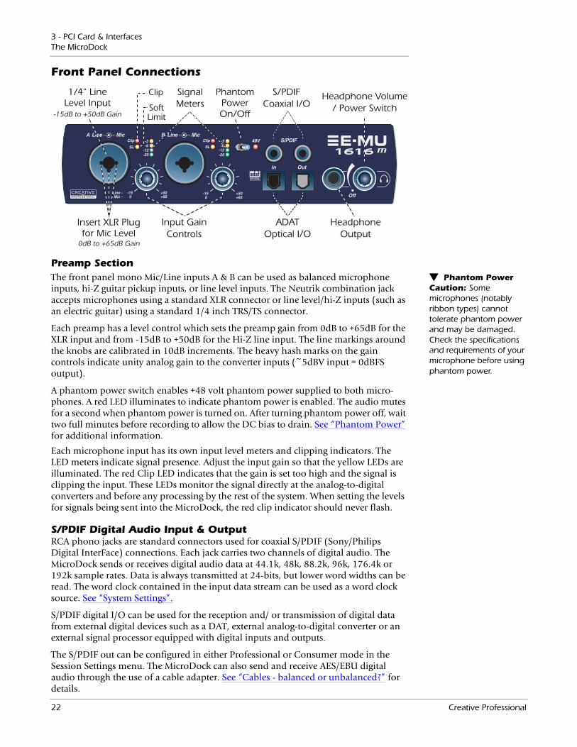
Front Panel Connections
Preamp Section Phantom Power Caution: Some microphones (notably ribbon types) cannot tolerate phantom power and may be damaged. Check the specifications and requirements of your microphone before using phantom power.
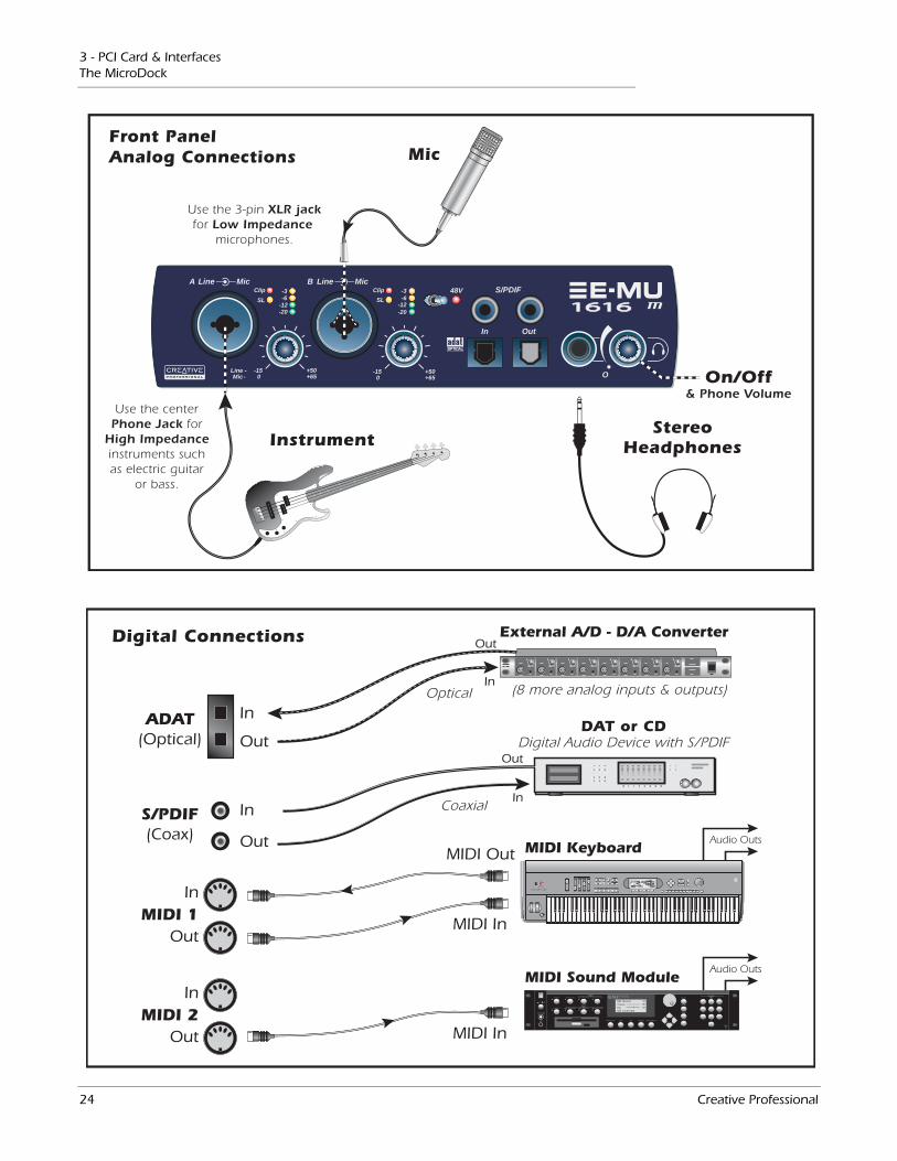
The front panel mono Mic/Line inputs A & B can be used as balanced microphone inputs, hi-Z guitar pickup inputs, or line level inputs. The Neutrik combination jack accepts microphones using a standard XLR connector or line level/hi-Z inputs (such as an electric guitar) using a standard 1/4 inch TRS/TS connector.
Each preamp has a level control which sets the preamp gain from 0dB to +65dB for the XLR input and from -15dB to +50dB for the Hi-Z line input. The line markings around the knobs are calibrated in 10dB increments. The heavy hash marks on the gain controls indicate unity analog gain to the converter inputs (~5dBV input = 0dBFS output).
A phantom power switch enables +48 volt phantom power supplied to both micro-phones. A red LED illuminates to indicate phantom power is enabled. The audio mutes for a second when phantom power is turned on. After turning phantom power off, wait two full minutes before recording to allow the DC bias to drain. See “Phantom Power” for additional information.
Each microphone input has its own input level meters and clipping indicators. The LED meters indicate signal presence. Adjust the input gain so that the yellow LEDs are illuminated. The red Clip LED indicates that the gain is set too high and the signal is clipping the input. These LEDs monitor the signal directly at the analog-to-digital converters and before any processing by the rest of the system. When setting the levels for signals being sent into the MicroDock, the red clip indicator should never flash.
S/PDIF Digital Audio Input & OutputRCA phono jacks are standard connectors used for coaxial S/PDIF (Sony/Philips Digital InterFace) connections. Each jack carries two channels of digital audio. The MicroDock sends or receives digital audio data at 44.1k, 48k, 88.2k, 96k, 176.4k or 192k sample rates. Data is always transmitted at 24-bits, but lower word widths can be read. The word clock contained in the input data stream can be used as a word clock source. See “System Settings”.
S/PDIF digital I/O can be used for the reception and/ or transmission of digital data from external digital devices such as a DAT, external analog-to-digital converter or an external signal processor equipped with digital inputs and outputs.
The S/PDIF out can be configured in either Professional or Consumer mode in the Session Settings menu. The MicroDock can also send and receive AES/EBU digital audio through the use of a cable adapter. See “Cables - balanced or unbalanced?” for details.
22 Creative Professional
3 - PCI Card & InterfacesThe MicroDock
ADAT Optical Digital Input & Output Important: When using any type of digital I/O such as S/PDIF or ADAT, you MUST sample sync the two devices or clicks and pops in the audio will result.
The ADAT optical connectors transmit and receive 8 channels of 24-bit audio using the ADAT type 1 & 2 formats. The word clock contained in the input data stream can be used as a word clock source. See “System Settings”. Optical connections have certain advantages such as immunity to electrical interference and ground loops. Make sure to use high quality glass fiber light pipes for connections longer than 1.5 meters.
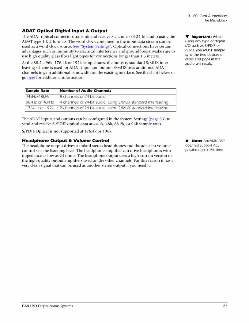
At the 88.2k, 96k, 176.4k or 192k sample rates, the industry standard S/MUX inter-leaving scheme is used for ADAT input and output. S/MUX uses additional ADAT channels to gain additional bandwidth on the existing interface. See the chart below or go here for additional information.
Sample Rate Number of Audio Channels
44kHz/48kHz 8 channels of 24-bit audio88kHz or 96kHz 4 channels of 24-bit audio, using S/MUX standard interleaving176kHz or 192kHz 2 channels of 24-bit audio, using S/MUX standard interleaving
The ADAT inputs and outputs can be configured in the System Settings (page 33) to send and receive S./PDIF optical data at 44.1k, 48k, 88.2k, or 96k sample rates.
S/PDIF Optical is not supported at 176.4k or 196k.
Note: PatchMix DSP does not support AC3 passthrough at this time.
Headphone Output & Volume ControlThe headphone output drives standard stereo headphones and the adjacent volume control sets the listening level. The headphone amplifier can drive headphones with impedance as low as 24 ohms. The headphone output uses a high-current version of the high-quality output amplifiers used on the other channels. For this reason it has a very clean signal that can be used as another stereo output if you need it.
E-MU PCI Digital Audio Systems 23
3 - PCI Card & InterfacesThe MicroDock
MIDI 1
S/PDIF(Coax)
ADAT(Optical)
MIDI Keyboard
EMULATOR
P R E S E T
S A M P L E
S E Q U E N C E R
P A G E
L E V E L
P R E S E T S E L E C T
R E A L T I M E C O N T R O L L E R SA S S I G N A B L E K E Y S
E N T E RE X I T
R E T U R N
0 .987654321
Digital Connections
DAT or CDDigital Audio Device with S/PDIF
(8 more analog inputs & outputs)
Coaxial
Optical
I
VOLUME
O
TRANSPOSE DIGITAL PROCESSINGSAMPLE MANAGEMENT
SAMPLE
PRESET
MASTER/GLOBAL
MULTIMODE PRESET MANAGEMENT DYNAMIC PROCESINGPRESET DEFINITION
DRIVE SELECT LOAD SAVE AUDITION TRIGGER MODEESCAPE
MIDI
ENTER
DEC/NO
INC/YES ABC
JKL
TUV
DEF
MNO
WXY
QZ
GHI
PRS
TRIGGERS
1 2 3
4 5 6
7 8 9
0
MIDI Sound Module
In
Out
In
MIDI 2Out
In
MIDI Out
In
In
Out
Out
MIDI In
Out
In
Out
MIDI In
1 2 3 4 5 6 7 8
External A/D - D/A Converter
Audio Outs
Audio Outs
LineA Mic
-15 0
Line -Mic -
Clip
+50
LineB Mic
+65-15 0
48V
+50+65
S/PDIF
In Out
-3-6
-12-20
SL
Clip -3-6
-12-20
SL
O
Instrument
Mic
StereoHeadphones
On/Off& Phone Volume
Front PanelAnalog Connections
Use the centerPhone Jack for
High Impedanceinstruments suchas electric guitar
or bass.
Use the 3-pin XLR jackfor Low Impedance
microphones.
24 Creative Professional
3 - PCI Card & InterfacesThe MicroDock
Rear Panel Connections
EDI
In
1L 1R 2L 2R
3L 3R2L 2R
Out
1L 1R
PhonoGnd2L 2R
1 2Out
48 VDC+ -
MIDI Cable
3
4 Balanced Line Level Inputs(configured as 2 stereo pairs)
Turntable Inputs(tied to line input 2)
TurntableGround
Alternate Outputs6 Balanced Line Level Outputs(configured as 3 stereo pairs)
MIDI PortConnector
48 Volt DCPower Input
Connect toE-MU 1010 PCI Card(same as outputs 1-3)
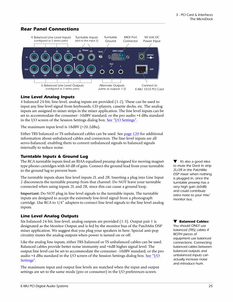
Line Level Analog Inputs4 balanced 24-bit, line-level, analog inputs are provided (1-2). These can be used to input any line level signal from keyboards, CD-players, cassette decks, etc. The analog inputs are assigned to mixer strips in the mixer application. The line level inputs can be set to accommodate the consumer -10dBV standard, or the pro audio +4 dBu standard in the I/O screen of the Session Settings dialog box. See “I/O Settings”.
The maximum input level is 18dBV (=20.2dBu).
Either TRS balanced or TS unbalanced cables can be used. See page 120 for additional information about unbalanced cables and connectors. The line-level inputs are all servo-balanced, enabling them to convert unbalanced signals to balanced signals internally to reduce noise.
Turntable Inputs & Ground Lug It’s also a good idea to mute the Dock In strip 2L/2R in the PatchMix DSP mixer when nothing is plugged in, since the turntable preamp has a very high gain (60dB) and could contribute extra noise to your mix/monitor bus.
The RCA turntable inputs feed an RIAA equalized preamp designed for moving magnet type phono cartridges with 60 dB of gain. Connect the ground lead from your turntable to the ground lug to prevent hum.
The turntable inputs share line level inputs 2L and 2R. Inserting a plug into Line Input 2 disconnects the turntable preamp from that channel. Do NOT leave your turntable connected when using inputs 2L and 2R, since this can cause a ground loop.
Important: Do NOT plug in line level signals to the turntable inputs. The turntable inputs are designed to accept the extremely low-level signal from a phonograph cartridge. Use RCA to 1/4” adapters to connect line level signals to the line level analog inputs.
Line Level Analog Outputs Balanced Cables: You should ONLY use balanced (TRS) cables if BOTH pieces of equipment use balanced connections. Connecting balanced cables between balanced outputs and unbalanced inputs can actually increase noise and introduce hum.
Six balanced 24-bit, line-level, analog outputs are provided (1-3). Output pair 1 is designated as the Monitor Output and is fed by the monitor bus of the PatchMix DSP mixer application. We suggest that you plug your speakers in here. Special anti-pop circuitry mutes the analog outputs when power is turned on or off.
Like the analog line inputs, either TRS balanced or TS unbalanced cables can be used. Balanced cables provide better noise immunity and +6dB higher signal level. The output line level can be set to accommodate the consumer -10dBV standard, or the pro audio +4 dBu standard in the I/O screen of the Session Settings dialog box. See “I/O Settings”.
The maximum input and output line levels are matched when the input and output settings are set to the same mode (pro or consumer) in the I/O preferences screen.
E-MU PCI Digital Audio Systems 25
3 - PCI Card & InterfacesThe MicroDock
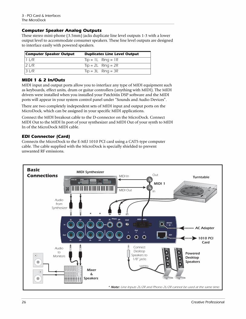
Computer Speaker Analog OutputsThese stereo mini-phone (3.5mm) jacks duplicate line level outputs 1-3 with a lower output level to accommodate consumer speakers. These line level outputs are designed to interface easily with powered speakers.
Computer Speaker Output Duplicates Line Level Output
1 L/R Tip = 1L Ring = 1R2 L/R Tip = 2L Ring = 2R3 L/R Tip = 3L Ring = 3R
MIDI 1 & 2 In/OutsMIDI input and output ports allow you to interface any type of MIDI equipment such as keyboards, effect units, drum or guitar controllers (anything with MIDI). The MIDI drivers were installed when you installed your PatchMix DSP software and the MIDI ports will appear in your system control panel under “Sounds and Audio Devices”.
There are two completely independent sets of MIDI input and output ports on the MicroDock, which can be assigned in your specific MIDI applications.
Connect the MIDI breakout cable to the D-connector on the MicroDock. Connect MIDI Out to the MIDI In port of your synthesizer and MIDI Out of your synth to MIDI In of the MicroDock MIDI cable.
EDI Connector (Card)Connects the MicroDock to the E-MU 1010 PCI card using a CAT5-type computer cable. The cable supplied with the MicroDock is specially shielded to prevent unwanted RF emissions.
EDI
In
1L 1R 2L 2R
3L 3R2L 2R
Out
1L 1R
PhonoGnd2L 2R
1 2Out
48 VDC+ -
MIDI Cable
3
BasicConnections Turntable
* *
MIDI 1
MIDI In
MIDI Out
PoweredDesktopSpeakers
MIDI Synthesizer
Mixer&
Speakers
Audiofrom
Synthesizer
Audioto
Monitors
ConnectDesktop
Speakers to1/8" jacks
1010 PCICard
AC Adapter
Stereo
In
Out
* Note: Line Inputs 2L/2R and Phono 2L/2R cannot be used at the same time.
26 Creative Professional

3 - PCI Card & InterfacesThe MicroDock
EDI
In
1L 1R 2L 2R
3L 3R2L 2R
Out
1L 1R
PhonoGnd2L 2R
1 2
Out
48 VDC+ -
MIDI Cable
3
Front Rear Ctr/Sub
LeftFront
RightFront
Center
Sub-Woofer
LeftRear
RightRear
5.1 Surround Speaker Connections
(with built-in power amps)
Multichannel WAVE to Surround Sound Speaker Channels (using the factory 5.1 DVD Playback Session)
WAVE Strip Surround Channels 1/4” Outputs 1/8” Outputs
E-DSP WAVE 1/2 Front Left/Front Right 1L = FL 1R = FR 1 (Tip = FL Ring = FR)
E-DSP WAVE 3/4 Center/Subwoofer 3L = C 3R = Sub 3 (Tip = C Ring = Sub)
E-DSP WAVE 5/6 Rear Left/Rear Right 2L = RL 2R = RR 2 (Tip = RL Ring = RR)
E-DSP WAVE 7/8 Side Left/Side Right N/A N/A
The 1/8” stereo jacks make it easy to connect to powered surround sound speakers. Only three stereo cables are necessary with many speaker systems (see above). The 1/8” jacks duplicate the 1/4” outputs.
You can connect the 1/8” stereo jacks to your surround speakers and connect the 1/4” outputs to your other gear for music creation. When you want to monitor in surround, simply open the 5.1 Session and turn on your surround speakers.
The chart below shows how to connect the outputs for 5.1 surround sound playback.
E-MU PCI Digital Audio Systems 27

3 - PCI Card & InterfacesThe MicroDock
28 Creative Professional
4 - The PatchMix DSP MixerPatchMix DSP
4 - The PatchMix DSP Mixer
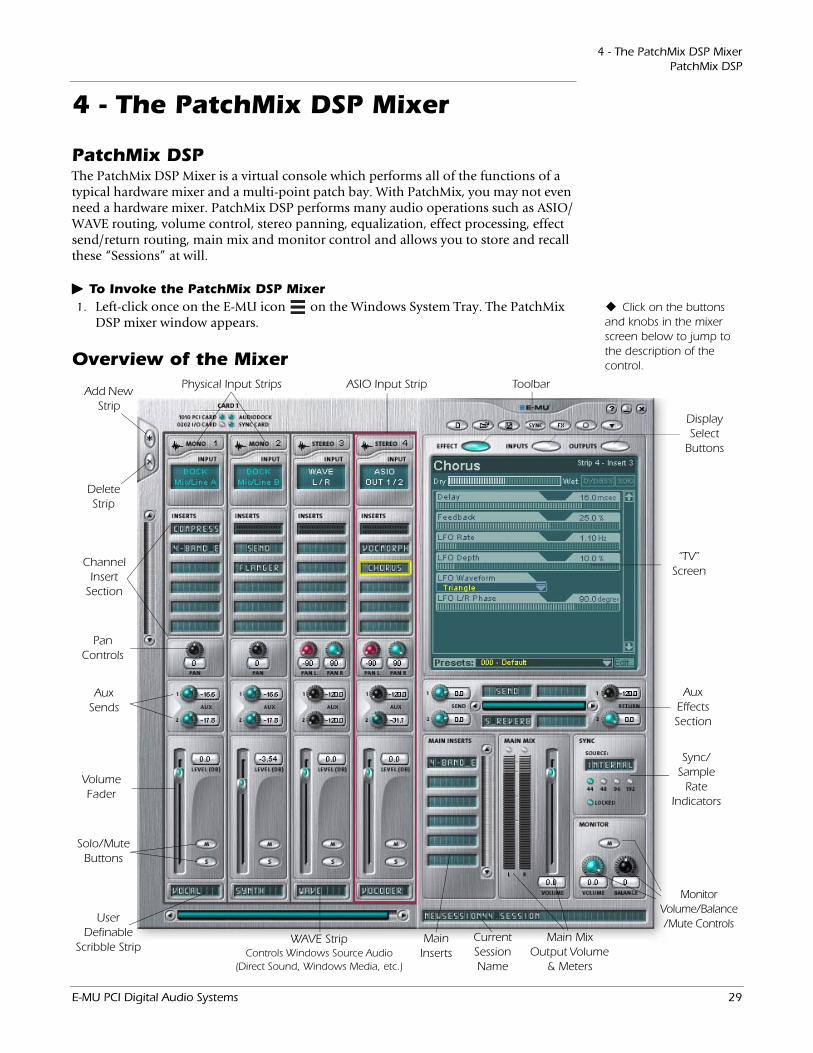
PatchMix DSPThe PatchMix DSP Mixer is a virtual console which performs all of the functions of a typical hardware mixer and a multi-point patch bay. With PatchMix, you may not even need a hardware mixer. PatchMix DSP performs many audio operations such as ASIO/WAVE routing, volume control, stereo panning, equalization, effect processing, effect send/return routing, main mix and monitor control and allows you to store and recall these “Sessions” at will.
To Invoke the PatchMix DSP MixerClick on the buttons
and knobs in the mixer screen below to jump to the description of the control.
1. Left-click once on the E-MU icon on the Windows System Tray. The PatchMix DSP mixer window appears.
Overview of the Mixer
Add New Strip
Aux Sends
Volume Fader
Pan Controls
Solo/Mute Buttons
Channel Insert
Section
Toolbar
Monitor Volume/Balance/Mute Controls
Main MixOutput Volume
& Meters
Main Inserts
UserDefinable
Scribble Strip
Display Select
Buttons
“TV” Screen
Aux Effects Section
Delete Strip
Sync/Sample
Rate Indicators
WAVE Strip Controls Windows Source Audio
(Direct Sound, Windows Media, etc.)
Physical Input Strips
CurrentSessionName
ASIO Input Strip
E-MU PCI Digital Audio Systems 29
4 - The PatchMix DSP MixerOverview of the Mixer
Mixer Window
Application Toolbar Lets you manage sessions and show/hide the various views.
Main Section Controls all the main levels, aux buses, and their inserts. This section also has a “TV” which shows parameters for the currently selected effect and the input/output patching. It also shows the session’s current sample rate and whether it’s set to internal or external clock.
Mixer Strips This section is located to the left of the Main Section and shows all the currently instantiated mixer strips. Mixer strips can represent Physical analog/digital inputs, or Host inputs such as ASIO or Direct Sound. Mixer strips can be added or deleted as necessary. This section can be resized by dragging the left edge of the frame.
Effects Palette This popup window is invoked by pressing the FX button in the toolbar. Iconic representations of all effects presets are shown here, organized by category. From this window, you can drag and drop effect presets into the insert slots available on the mixer strips and main section aux buses and main inserts.
The Mixer consists of four main sections.
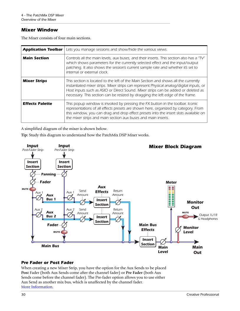
A simplified diagram of the mixer is shown below.
Tip: Study this diagram to understand how the PatchMix DSP Mixer works.
Pre Fader or Post FaderWhen creating a new Mixer Strip, you have the option for the Aux Sends to be placed Post Fader (both Aux Sends come after the channel fader) or Pre Fader (both Aux Sends come before the channel fader). The Pre-fader option allows you to use either Aux Send as another mix bus, which is unaffected by the channel fader. More Information.
AuxBus 1
Aux 2
Aux 1
Aux 2
AuxEffects
InsertSection
InsertSection
InsertSection
InsertSection
Input
AuxBus 2
Post-Fader StripInput
Pre-Fader Strip
ReturnAmount
Output 1L/1R& Headphones
SendAmount
ReturnAmount
SendAmount
Aux 1
Fader
Fader
Panning
Main Bus MainOut
MonitorOut
MainLevel
MonitorLevel
Meter
Main BusEffects
InsertSection
MUTE
MUTE
MUTE
Mixer Block Diagram
30 Creative Professional

4 - The PatchMix DSP MixerE-MU Icon in the Windows Taskbar
E-MU Icon in the Windows TaskbarRight-clicking on the E-MU icon in the Windows taskbar calls the following window.
Restore Defaults: Always try this option first if PatchMix is crashing or if you are having any other strange audio problems.
Opens the PatchMix DSP Mixer.
Calls the PatchMix DSP help system.
Disables the splash screen that appears at boot-up.
Restores the default PatchMix DSP and driver settings.
Closes the PatchMix DSP background program, disabling use of all audio I/O from the E-MU hardware. Open the Patch-Mix DSP application to start audio again.
Right-Click Here
When unchecked, FX are not loaded until needed, resulting in faster computer boot.
The Toolbar
New Session
Open Session
Save Session
Session Settings
Show/HideEffects
Global Prefs
“About”PatchMix DSP
New Session Calls up the “New Session” dialog box. New Session.
Open Session Calls up the standard “Open” dialog box, allowing you to open a saved Session.
Save Session Calls up the standard “Save” or “Save As…”þdialog boxes, allowing you to save the current Session.
Show/Hide Effects Toggle button that shows or hides the FX palette.
Session Settings Calls up the Sessions Settings window. Session Settings.
Global Preferences Calls up the Global Preferences window.
About PatchMix DSP
Right-Click on the E-MU logo to view the “About PatchMix DSP” screen, which provides the software and firmware version numbers and other information.
Click the buttons in the toolbar to learn about their function.
E-MU PCI Digital Audio Systems 31
4 - The PatchMix DSP MixerThe Session
The SessionThe current state of the PatchMix DSP mixer (fader settings, effects routings…every-thing!) can be saved as a Session. Whenever you create or modify a mixer setup, all you have to do is Save it to be able to recall it at a later time.
Before you begin using PatchMix DSP, you need to set it up to be compatible with the other software applications you may be running. The most important consideration is your system sample rate. PatchMix DSP and any applications or other digital gear you are using must be set to the same sample rate. PatchMix DSP can run at 44.1kHz, 48kHz, 88kHz, 96kHz, 176.4 kHz or 192kHz, but its complete set of features are only available at 44.1kHz or 48kHz. See “Using High Sample Rates” on page 111 for details.
Once the sample rate is set, you can only easily switch between 44.1k and 48k. You cannot switch between 44/48k and 88k/96k/176k/192k. With a change to these higher sample rates, you must start a new session.
Important: When using any form of digital input, you MUST synchronize the Digital Audio System to the external digital device (S/PDIF/ADAT).
You can also set up an external sync source, thereby obtaining the sample rate from some other device or application. External sync can be obtained from the ADAT input or S/PDIF input. If the session is set at 44.1kHz or 48kHz and the external source is coming in at a higher rate (such as 96k), the Sync Indicator will be extinguished (off), but PatchMix will attempt to receive the external data. The two units are NOT sample locked however, and you should correct this condition to avoid intermittent clicks in the audio. Always check for the presence of the LOCKED indicator whenever you are using a digital interface.
PatchMix DSP comes with several session templates to choose from so when you create a new session you can either create a “blank” session based around a designated sample rate, or select from a list of template starting points.
In a PatchMix DSP session the number of strips in the mixer is dynamically config-urable. This allows you to create only those strips you need up to a maximum number determined by available DSP resources and available inputs.
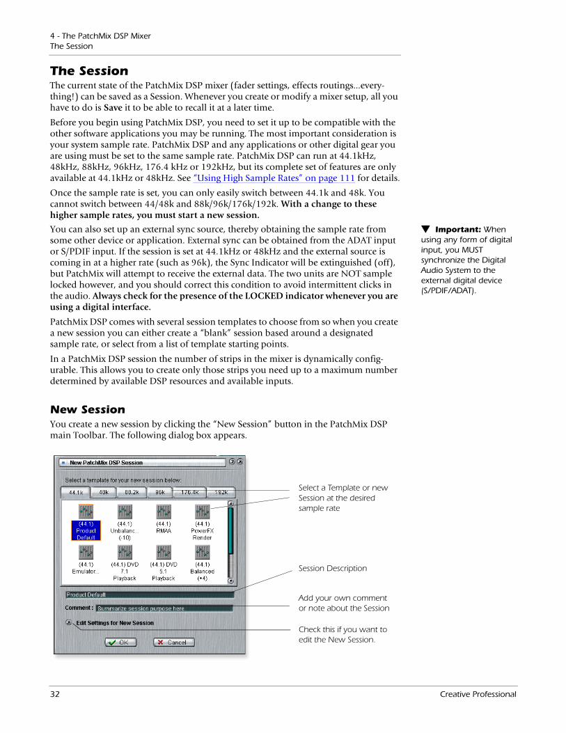
New SessionYou create a new session by clicking the “New Session” button in the PatchMix DSP main Toolbar. The following dialog box appears.
Select a Template or new Session at the desired sample rate
Session Description
Add your own comment or note about the Session
Check this if you want to edit the New Session.
32 Creative Professional

4 - The PatchMix DSP MixerThe Session
You can now select one of the factory template sessions. The factory templates are pre-programmed with specific setups such as audio recording or mixing. The selector tabs categorize Template Sessions into three groups based on sample rate, 44.1k/48k, 88k/96k, or 176k/192k.
You can create your own templates by simply copying or saving sessions into the “Session Templates” folder (Program Files\Creative Professional\E-MU PatchMix DSP\Session Templates).
There is also a Comment area that you can use to give yourself some clue as to what you were thinking when you created the session.
Selecting a Session at 176.4kHZ or 192kHzWhen operating at 176.4k or 192k sample rates, the number of I/O channels are slightly reduced. At these high sample rates you must select one of three types of sessions each containing a different I/O configuration. Please see page 111 for details.
Open SessionTo Open a saved session, click on the Open Session button. A dialog box appears allowing you to choose one of your saved Sessions to open. Choose one of your saved sessions and click on the Open button.
Save SessionTo Save a session, click on the Save Session button. A Save dialog box appears allowing you to choose a location in which to save the current Session. The “My Sessions” folder is chosen by default.
Get in the habit of saving the session whenever you have created a special mixer setup. This will make your life much easier as you can recall a setup for many different audio modes such as: recording, mixing, special ASIO routings, etc.
Session Settings
System SettingsPressing the Session Settings button on the toolbar brings up the System Settings window shown below. Click the tabs to select System or I/O options.
E-MU PCI Digital Audio Systems 33
4 - The PatchMix DSP MixerThe Session
• Internal/External Clock Selects between internal or external word clock source as the master clock source for the system
• Sample Rate Selects the sample rate when using internal clock. Your choices are: 44.1kHz, 48kHz, 88.2kHz, 96kHz, 176.4kHz, 192kHz.
• External Clock Source (ext. clock only)
Select from: ADAT, or S/PDIF as an external sample clock source.
The System Settings include the following: Note: if set to
“External” without an external clock present, PatchMix DSP defaults to the internal 48kHz clock rate.
Using External ClockWhenever you are using any digital I/O such as ADAT or S/PDIF, one of the digital devices MUST supply the master clock to the others. This master clock runs at the system sample rate and can be embedded into a data stream such as S/PDIF or ADAT. Common symptoms of unsynced digital audio include, random clicks or pops in the audio or failure of the digital stream to be recognized. Always check for the presence of the “LOCKED” indicator whenever you are using a digital interface.
If an External Clock is interrupted or switched after the Session has been created (except between 44.1k <-> 48k), the “LOCKED” indicator will be extinguished and PatchMix will attempt to receive the external data. The two units are NOT sample locked however, and you should correct this condition to avoid intermittent clicks in the audio.
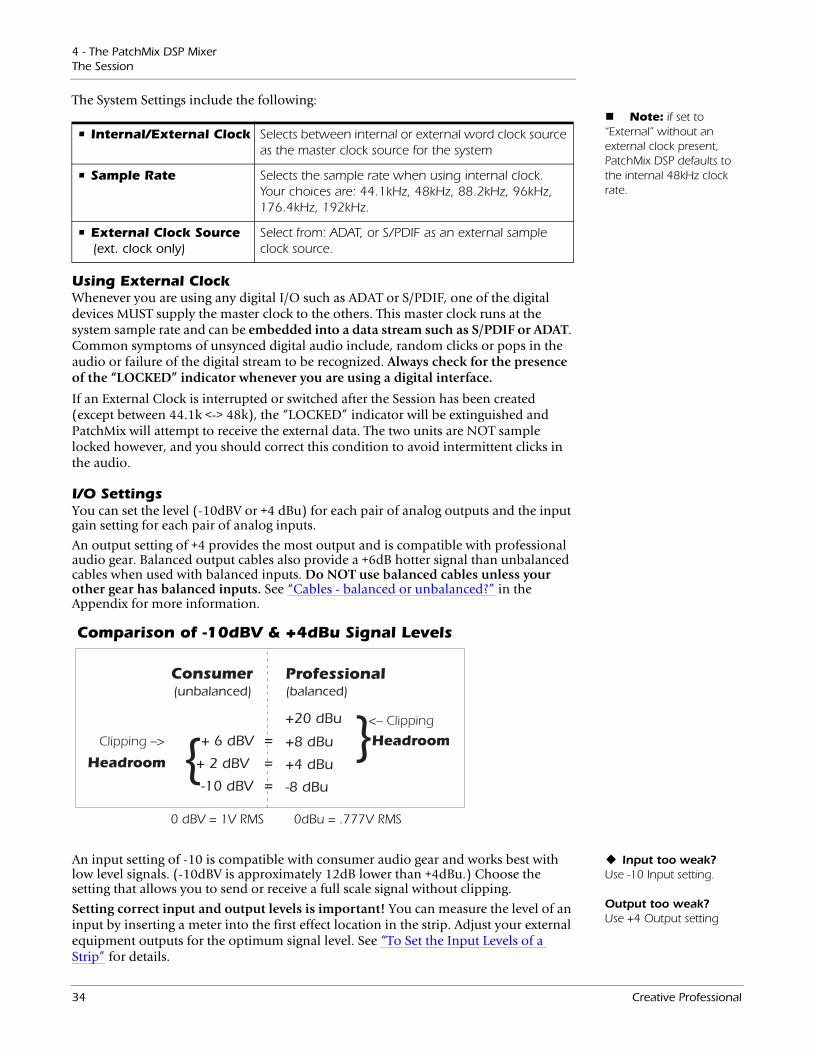
I/O SettingsYou can set the level (-10dBV or +4 dBu) for each pair of analog outputs and the input gain setting for each pair of analog inputs.
An output setting of +4 provides the most output and is compatible with professional audio gear. Balanced output cables also provide a +6dB hotter signal than unbalanced cables when used with balanced inputs. Do NOT use balanced cables unless your other gear has balanced inputs. See “Cables - balanced or unbalanced?” in the Appendix for more information.
Comparison of -10dBV & +4dBu Signal Levels
0 dBV = 1V RMS 0dBu = .777V RMS
Input too weak? Use -10 Input setting. Output too weak? Use +4 Output setting
An input setting of -10 is compatible with consumer audio gear and works best with low level signals. (-10dBV is approximately 12dB lower than +4dBu.) Choose the setting that allows you to send or receive a full scale signal without clipping.
Setting correct input and output levels is important! You can measure the level of an input by inserting a meter into the first effect location in the strip. Adjust your external equipment outputs for the optimum signal level. See “To Set the Input Levels of a Strip” for details.
34 Creative Professional
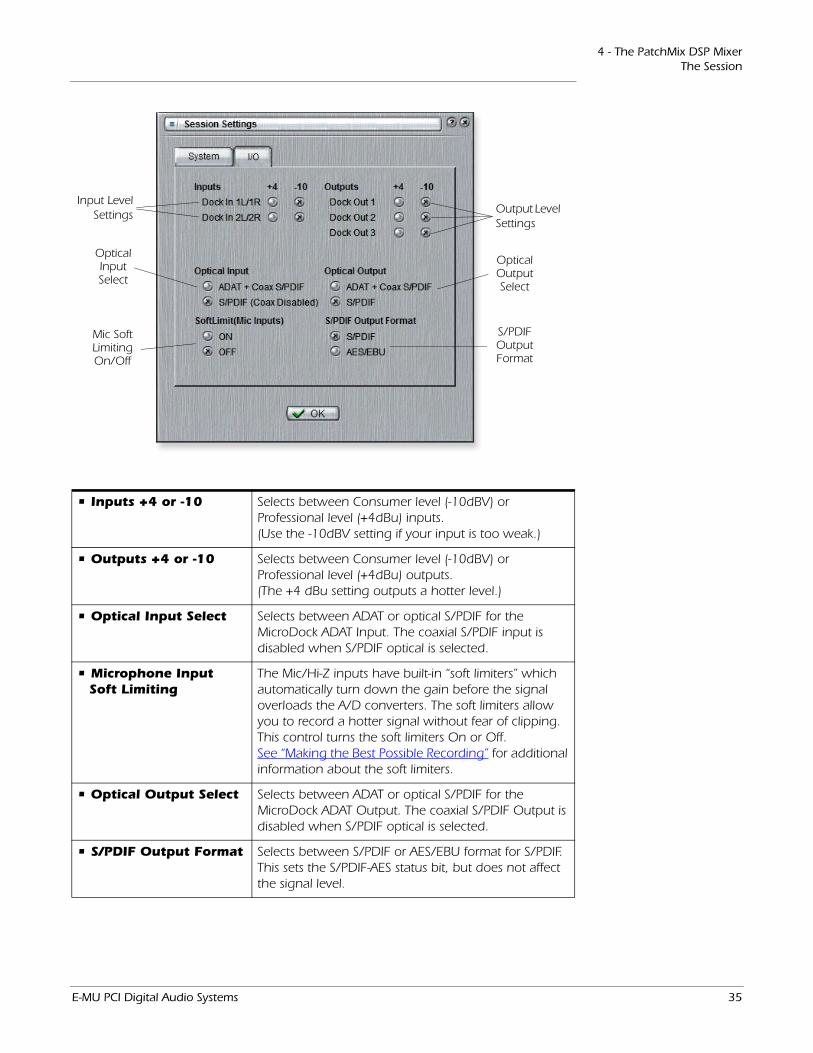
4 - The PatchMix DSP MixerThe Session
Output Level Settings
Input Level Settings
Optical OutputSelect
Optical InputSelect
S/PDIF Output Format
Mic SoftLimiting On/Off
• Inputs +4 or -10 Selects between Consumer level (-10dBV) or Professional level (+4dBu) inputs. (Use the -10dBV setting if your input is too weak.)
• Outputs +4 or -10 Selects between Consumer level (-10dBV) or Professional level (+4dBu) outputs. (The +4 dBu setting outputs a hotter level.)
• Optical Input Select Selects between ADAT or optical S/PDIF for the MicroDock ADAT Input. The coaxial S/PDIF input is disabled when S/PDIF optical is selected.
• Microphone Input Soft Limiting
The Mic/Hi-Z inputs have built-in “soft limiters” which automatically turn down the gain before the signal overloads the A/D converters. The soft limiters allow you to record a hotter signal without fear of clipping. This control turns the soft limiters On or Off. See “Making the Best Possible Recording” for additional information about the soft limiters.
• Optical Output Select Selects between ADAT or optical S/PDIF for the MicroDock ADAT Output. The coaxial S/PDIF Output is disabled when S/PDIF optical is selected.
• S/PDIF Output Format Selects between S/PDIF or AES/EBU format for S/PDIF. This sets the S/PDIF-AES status bit, but does not affect the signal level.
E-MU PCI Digital Audio Systems 35
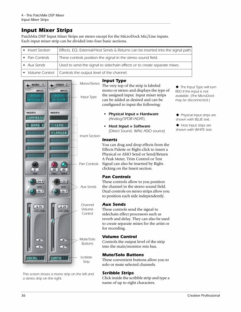
4 - The PatchMix DSP MixerInput Mixer Strips
Input Mixer StripsPatchMix DSP Input Mixer Strips are stereo except for the MicroDock Mic/Line inputs. Each input mixer strip can be divided into four basic sections.
• Insert Section Effects, EQ, External/Host Sends & Returns can be inserted into the signal path.
• Pan Controls These controls position the signal in the stereo sound field.
• Aux Sends Used to send the signal to sidechain effects or to create separate mixes.
• Volume Control Controls the output level of the channel.
Mono/Stereo
Input Type
Insert Section
Aux Sends
Channel Volume Control
Pan Controls
Mute/Solo Buttons
ScribbleStrip
This screen shows a mono strip on the left and a stereo strip on the right.
Input TypeThe very top of the strip is labeled mono or stereo and displays the type of the assigned input. Input mixer strips can be added as desired and can be configured to input the following:
• Physical Input = Hardware (Analog/SPDIF/ADAT).
• Host Input = Software (Direct Sound, WAV, ASIO source)
InsertsYou can drag and drop effects from the Effects Palette or Right-click to insert a Physical or ASIO Send or Send/Return A Peak Meter, Trim Control or Test Signal can also be inserted by Right-clicking on the Insert section.
Pan ControlsThese controls allow to you position the channel in the stereo sound field. Dual controls on stereo strips allow you to position each side independently.
Aux SendsThese controls send the signal to sidechain effect processors such as reverb and delay. They can also be used to create separate mixes for the artist or for recording.
Volume ControlControls the output level of the strip into the main/monitor mix bus.
Mute/Solo ButtonsThese convenient buttons allow you to solo or mute selected channels.
Scribble StripsClick inside the scribble strip and type a name of up to eight characters.
Physical input strips are shown with BLUE text.
Host input strips are shown with WHITE text.
The Input Type will turn RED if the input is not available. (The MicroDock may be disconnected.)
36 Creative Professional
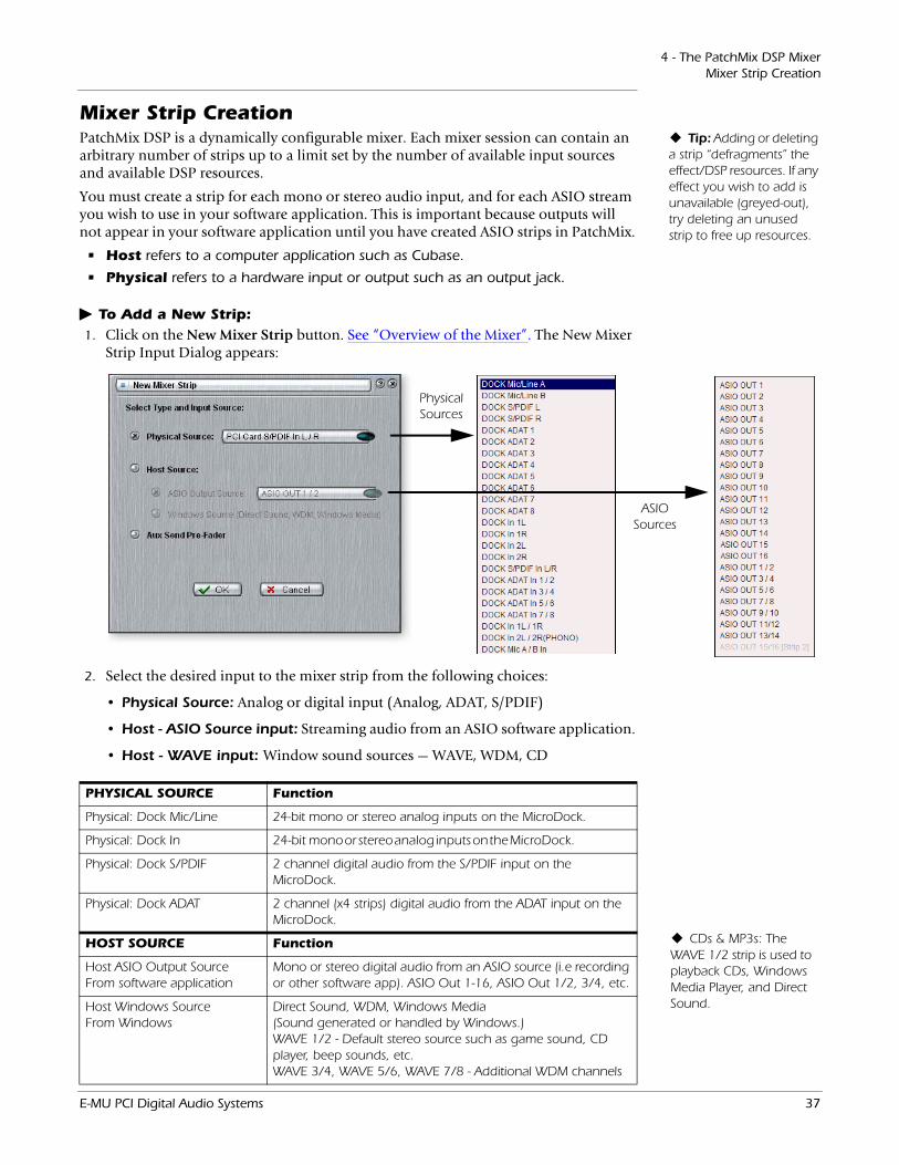
4 - The PatchMix DSP MixerMixer Strip Creation
Mixer Strip CreationTip: Adding or deleting
a strip “defragments” the effect/DSP resources. If any effect you wish to add is unavailable (greyed-out), try deleting an unused strip to free up resources.
PatchMix DSP is a dynamically configurable mixer. Each mixer session can contain an arbitrary number of strips up to a limit set by the number of available input sources and available DSP resources.
You must create a strip for each mono or stereo audio input, and for each ASIO stream you wish to use in your software application. This is important because outputs will not appear in your software application until you have created ASIO strips in PatchMix.
• Host refers to a computer application such as Cubase.
• Physical refers to a hardware input or output such as an output jack.
To Add a New Strip:
Physical Sources
ASIO Sources
1. Click on the New Mixer Strip button. See “Overview of the Mixer”. The New Mixer Strip Input Dialog appears:
2. Select the desired input to the mixer strip from the following choices:
• Physical Source: Analog or digital input (Analog, ADAT, S/PDIF)
• Host - ASIO Source input: Streaming audio from an ASIO software application.
• Host - WAVE input: Window sound sources — WAVE, WDM, CD
CDs & MP3s: The WAVE 1/2 strip is used to playback CDs, Windows Media Player, and Direct Sound.
PHYSICAL SOURCE Function
Physical: Dock Mic/Line 24-bit mono or stereo analog inputs on the MicroDock.
Physical: Dock In 24-bit mono or stereo analog inputs on the MicroDock.
Physical: Dock S/PDIF 2 channel digital audio from the S/PDIF input on the MicroDock.
Physical: Dock ADAT 2 channel (x4 strips) digital audio from the ADAT input on the MicroDock.
HOST SOURCE Function
Host ASIO Output Source From software application
Mono or stereo digital audio from an ASIO source (i.e recording or other software app). ASIO Out 1-16, ASIO Out 1/2, 3/4, etc.
Host Windows Source From Windows
Direct Sound, WDM, Windows Media (Sound generated or handled by Windows.)WAVE 1/2 - Default stereo source such as game sound, CD player, beep sounds, etc. WAVE 3/4, WAVE 5/6, WAVE 7/8 - Additional WDM channels
E-MU PCI Digital Audio Systems 37
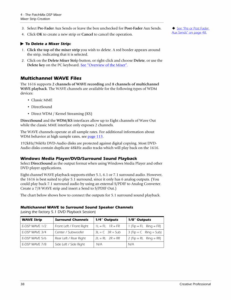
4 - The PatchMix DSP MixerMixer Strip Creation
See “Pre or Post Fader Aux Sends” on page 48.
3. Select Pre-Fader Aux Sends or leave the box unchecked for Post-Fader Aux Sends.
4. Click OK to create a new strip or Cancel to cancel the operation.
To Delete a Mixer Strip:
1. Click the top of the mixer strip you wish to delete. A red border appears around the strip, indicating that it is selected.
2. Click on the Delete Mixer Strip button, or right-click and choose Delete, or use the Delete key on the PC keyboard. See “Overview of the Mixer”.
Multichannel WAVE FilesThe 1616 supports 2 channels of WAVE recording and 8 channels of multichannel WAVE playback. The WAVE channels are available for the following types of WDM devices:
• Classic MME
• DirectSound
• Direct WDM / Kernel Streaming (KS)
DirectSound and the WDM/KS interfaces allow up to Eight channels of Wave Out while the classic MME interface only exposes 2 channels.
The WAVE channels operate at all sample rates. For additional information about WDM behavior at high sample rates, see page 113.
192kHz/96kHz DVD-Audio disks are protected against digital copying. Most DVD-Audio disks contain duplicate 48kHz audio tracks which will play back on the 1616.
Windows Media Player/DVD/Surround Sound PlaybackSelect DirectSound as the output format when using Windows Media Player and other DVD player applications.
Eight channel WAVE playback supports either 5.1, 6.1 or 7.1 surround audio. However, the 1616 is best suited to play 5.1 surround, since it only has 6 analog outputs. (You could play back 7.1 surround audio by using an external S/PDIF to Analog Converter. Create a 7/8 WAVE strip and insert a Send to S/PDIF Out.)
The chart below shows how to connect the outputs for 5.1 surround sound playback.
Multichannel WAVE to Surround Sound Speaker Channels (using the factory 5.1 DVD Playback Session)
WAVE Strip Surround Channels 1/4” Outputs 1/8” Outputs
E-DSP WAVE 1/2 Front Left / Front Right 1L = FL 1R = FR 1 (Tip = FL Ring = FR)
E-DSP WAVE 3/4 Center / Subwoofer 3L = C 3R = Sub 3 (Tip = C Ring = Sub)
E-DSP WAVE 5/6 Rear Left / Rear Right 2L = RL 2R = RR 2 (Tip = RL Ring = RR)
E-DSP WAVE 7/8 Side Left / Side Right N/A N/A
38 Creative Professional

4 - The PatchMix DSP MixerMixer Strip Creation
Insert SectionThe Insert Section is next in line. PatchMix DSP effects can be selected from the Effects Palette and dropped into the insert locations. See “The Effects Palette”. Any number of effects can be inserted in series.
The Inserts are also used to patch your audio inputs into ASIO/WAVE and external equipment. ASIO/WAVE Sends, External Sends and External Send/Returns can be dropped into the insert section to route the signal anywhere you want.
You have to create an ASIO strip or ASIO Send in order to activate these ASIO channels in your software.
The Insert/Patch Bay is incredibly flexible. Want to send the input of the strip to your software recording software? Just insert a HOST ASIO Send into the insert section of the strip. That input is now available in your ASIO software.
Suppose you wanted to record a submix of several inputs. Simply place a HOST ASIO SEND into the Aux Insert section and turn up the Aux sends on the input channels you want in the mix (as shown in the Mixer Overview on page 29). Note that Mic/Line A and B are routed to Aux Send 1, which has a HOST ASIO SEND insert to the recording application.
The following types of inserts can be selected.
Hardware Effect Reverb, EQ, Compressor, Flanger, etc. using PatchMix DSP’s effects which do not load your CPU.
Host ASIO Send Splits off the signal and sends it to an ASIO host input such as a software audio recorder or anything that uses ASIO.
ASIO Direct Monitor
Sends the signal to a selected ASIO host input, then returns a selected ASIO host output to the chain.
Ext. Send/Return Sends signal to a selected external output, then returns it to the chain via a physical input.
External Send Sends the signal to an external output. See “To Add a Send Insert:”.
Peak Meter Peak meters allow you to monitor the signal level anywhere in the chain. See “Meter Inserts”.
Trim Pot You can insert a gain control with up to 30 dB of gain or attenu-ation. A peak level meter and phase inverter are also included. See “Trim Pot Insert”.
Test Tone This special insert outputs a calibrated sine wave or noise source, which can be used to track down audio problems. See “Test Tone/Signal Generator Insert”.
Working with InsertsThe Inserts are one of most powerful features of the PatchMix DSP system as they allow you to configure the mixer for a wide variety of applications.
To Add an Effect to an Insert Location:
1. Press the FX button. The effects palette appears.
2. The effects are organized into categories. Click on a folder to open it.
3. Select the effect you want, drag it over the insert section, then drop it into an insert location.
4. To rearrange the order of effects, simply drag and drop them into the desired order.
E-MU PCI Digital Audio Systems 39
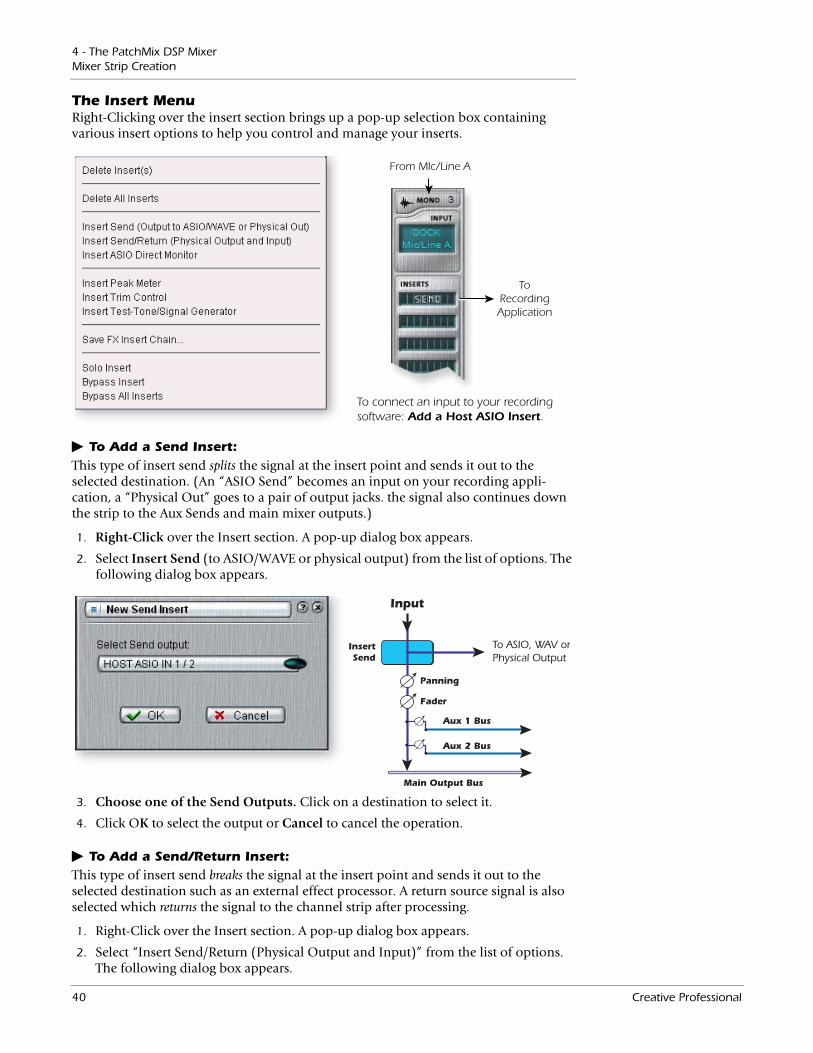
4 - The PatchMix DSP MixerMixer Strip Creation
The Insert MenuRight-Clicking over the insert section brings up a pop-up selection box containing various insert options to help you control and manage your inserts.
ToRecordingApplication
From MIc/Line A
To connect an input to your recording software: Add a Host ASIO Insert.
To Add a Send Insert:This type of insert send splits the signal at the insert point and sends it out to the selected destination. (An “ASIO Send” becomes an input on your recording appli-cation, a “Physical Out” goes to a pair of output jacks. the signal also continues down the strip to the Aux Sends and main mixer outputs.)
InsertSend
Input
Fader
Panning
Main Output Bus
Aux 1 Bus
Aux 2 Bus
To ASIO, WAV orPhysical Output
1. Right-Click over the Insert section. A pop-up dialog box appears.
2. Select Insert Send (to ASIO/WAVE or physical output) from the list of options. The following dialog box appears.
3. Choose one of the Send Outputs. Click on a destination to select it.
4. Click OK to select the output or Cancel to cancel the operation.
To Add a Send/Return Insert:This type of insert send breaks the signal at the insert point and sends it out to the selected destination such as an external effect processor. A return source signal is also selected which returns the signal to the channel strip after processing.
1. Right-Click over the Insert section. A pop-up dialog box appears.
2. Select “Insert Send/Return (Physical Output and Input)” from the list of options. The following dialog box appears.
40 Creative Professional
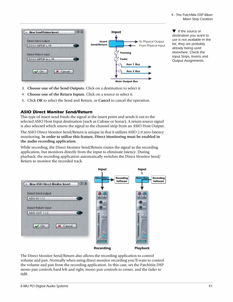
4 - The PatchMix DSP MixerMixer Strip Creation
InsertSend/Return
Input
Fader
Panning
Main Output Bus
Aux 1 Bus
Aux 2 Bus
To Physical OutputFrom Physical Input
If the source or destination you want to use is not available in the list, they are probably already being used elsewhere. Check the input Strips, Inserts and Output Assignments.
3. Choose one of the Send Outputs. Click on a destination to select it.
4. Choose one of the Return Inputs. Click on a source to select it.
5. Click OK to select the Send and Return, or Cancel to cancel the operation.
ASIO Direct Monitor Send/ReturnThis type of insert send breaks the signal at the insert point and sends it out to the selected ASIO Host Input destination (such as Cubase or Sonar). A return source signal is also selected which returns the signal to the channel strip from an ASIO Host Output.
The ASIO Direct Monitor Send/Return is unique in that it utilizes ASIO 2.0 zero-latency monitoring. In order to utilize this feature, Direct Monitoring must be enabled in the audio recording application.
While recording, the Direct Monitor Send/Return routes the signal to the recording application, but monitors directly from the input to eliminate latency. During playback, the recording application automatically switches the Direct Monitor Send/Return to monitor the recorded track.
Input Input
RecordingSoftware
RecordingSoftware
Direct MonDirect Mon
Recording Playback
The Direct Monitor Send/Return also allows the recording application to control volume and pan. Normally when using direct monitor recording you’ll want to control the volume and pan from the recording application. In this case, set the PatchMix DSP stereo pan controls hard left and right, mono pan controls to center, and the fader to 0dB.
E-MU PCI Digital Audio Systems 41
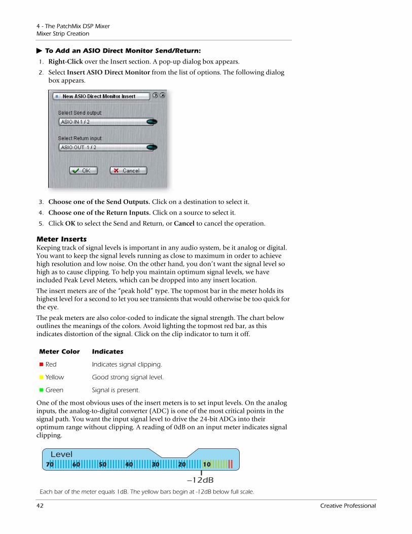
4 - The PatchMix DSP MixerMixer Strip Creation
To Add an ASIO Direct Monitor Send/Return:
1. Right-Click over the Insert section. A pop-up dialog box appears.
2. Select Insert ASIO Direct Monitor from the list of options. The following dialog box appears.
3. Choose one of the Send Outputs. Click on a destination to select it.
4. Choose one of the Return Inputs. Click on a source to select it.
5. Click OK to select the Send and Return, or Cancel to cancel the operation.
Meter InsertsKeeping track of signal levels is important in any audio system, be it analog or digital. You want to keep the signal levels running as close to maximum in order to achieve high resolution and low noise. On the other hand, you don’t want the signal level so high as to cause clipping. To help you maintain optimum signal levels, we have included Peak Level Meters, which can be dropped into any insert location.
The insert meters are of the “peak hold” type. The topmost bar in the meter holds its highest level for a second to let you see transients that would otherwise be too quick for the eye.
The peak meters are also color-coded to indicate the signal strength. The chart below outlines the meanings of the colors. Avoid lighting the topmost red bar, as this indicates distortion of the signal. Click on the clip indicator to turn it off.
Meter Color Indicates
Red Indicates signal clipping.
Yellow Good strong signal level.
Green Signal is present.
--12dB
Level10203040506070
Each bar of the meter equals 1dB. The yellow bars begin at -12dB below full scale.
One of the most obvious uses of the insert meters is to set input levels. On the analog inputs, the analog-to-digital converter (ADC) is one of the most critical points in the signal path. You want the input signal level to drive the 24-bit ADCs into their optimum range without clipping. A reading of 0dB on an input meter indicates signal clipping.
42 Creative Professional

4 - The PatchMix DSP MixerMixer Strip Creation
The insert meters are also useful to monitor incoming digital signals such as ADAT, ASIO or S/PDIF to make sure the mixer is receiving a proper signal level. They’re also great for troubleshooting, since you can place them virtually anywhere in the mixer.
To Insert a Meter
1. Right-Click on an Insert location of the mixer strip. A pop-up dialog box appears.
2. Select Insert Peak Meter. A stereo peak meter appears in the insert location.
3. Select Effect in the Main Section. The meters are now shown in high resolution in the TV screen.
To Set the Input Levels of a Strip
1. Select the topmost Insert location on a mixer strip and insert a meter (see above).
Input too weak? Use -10 Input setting. Output too weak? Use +4 Output setting
2. Left-click on the meter insert to see the meter in the TV screen.
3. Feed your audio signal to the input of the mixer strip. The meter should now show the signal level.
4. Adjust the output level of the external device (synthesizer, instrument, preamp, etc.) feeding the MicroDock. The meter should be in the yellow region most of the time with occasional forays into the red. If the clip indicator ever comes on, reduce the signal level.
5. Each analog input pair has its own Input Pad (-10dBV or +4dBu) which controls the input signal range. Changing the I/O settings can add or subtract 12dB. Check these settings if you cannot set the proper input level. See “I/O Settings”.
Making the Best Possible RecordingMaking a good digital recording is easier than ever thanks to the high resolution 24-bit A-D converters on your Digital Audio System. These converters are much more forgiving than the 12-bit or 16-bit converters of the past. Even so, to get the best perfor-mance possible, you'll need to follow a few basic guidelines.
First, whenever you input an analog signal to the Digital Audio System, make sure that you're feeding the A-D converters with an optimum signal level. The quality of a digital recording is directly related to the signal level you feed into the A-D converters. If the analog input level is set too low, you lose resolution—if it's set too high, the A-D converters will clip.
To measure the input level, simply add an insert meter to the channel strip in PatchMix DSP. These meters are accurately calibrated to display 1dB for each bar on the meter. You can enlarge the meter view by clicking on the insert meter in a strip and selecting the “Effect” button at the top of the TV screen.
The “I/O Settings” in the Digital Audio System allow you to set the input levels to -10dBV (consumer equipment level) or +4dBu (professional equipment level) for each analog input. This control sets the overall input level to match your other gear, but to get the best possible recording you need to fine tune the level further.
In order to supply the correct input level, you’ll need to adjust the output of your analog source (electric instrument or preamp) so that the input level comes close to 0dB without ever going over.
Play your input source signal while watching the insert meter in the strip. The signal should go into the yellow area frequently, but never into the red. Adjust the level of your source until you have a good level. If the signal is way too strong or too weak, you
E-MU PCI Digital Audio Systems 43
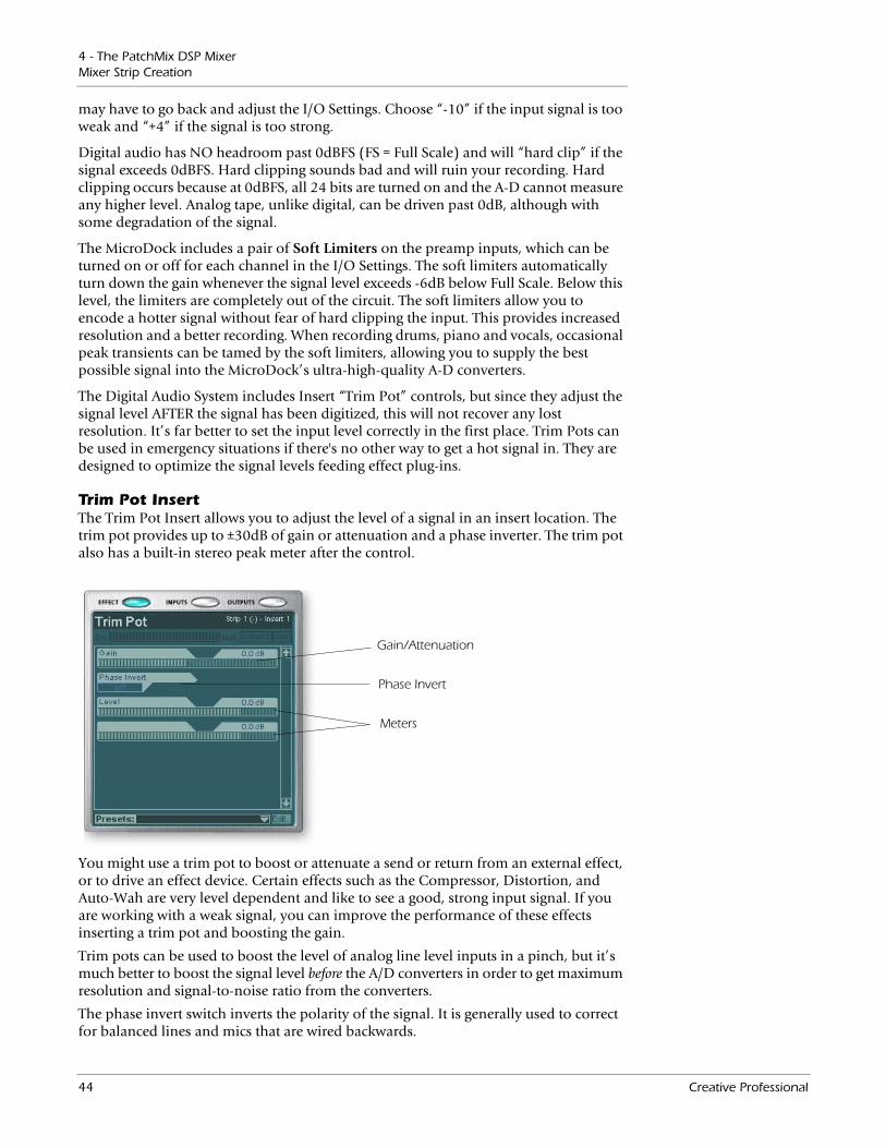
4 - The PatchMix DSP MixerMixer Strip Creation
may have to go back and adjust the I/O Settings. Choose “-10” if the input signal is too weak and “+4” if the signal is too strong.
Digital audio has NO headroom past 0dBFS (FS = Full Scale) and will “hard clip” if the signal exceeds 0dBFS. Hard clipping sounds bad and will ruin your recording. Hard clipping occurs because at 0dBFS, all 24 bits are turned on and the A-D cannot measure any higher level. Analog tape, unlike digital, can be driven past 0dB, although with some degradation of the signal.
The MicroDock includes a pair of Soft Limiters on the preamp inputs, which can be turned on or off for each channel in the I/O Settings. The soft limiters automatically turn down the gain whenever the signal level exceeds -6dB below Full Scale. Below this level, the limiters are completely out of the circuit. The soft limiters allow you to encode a hotter signal without fear of hard clipping the input. This provides increased resolution and a better recording. When recording drums, piano and vocals, occasional peak transients can be tamed by the soft limiters, allowing you to supply the best possible signal into the MicroDock’s ultra-high-quality A-D converters.
The Digital Audio System includes Insert “Trim Pot” controls, but since they adjust the signal level AFTER the signal has been digitized, this will not recover any lost resolution. It’s far better to set the input level correctly in the first place. Trim Pots can be used in emergency situations if there's no other way to get a hot signal in. They are designed to optimize the signal levels feeding effect plug-ins.
Trim Pot InsertThe Trim Pot Insert allows you to adjust the level of a signal in an insert location. The trim pot provides up to ±30dB of gain or attenuation and a phase inverter. The trim pot also has a built-in stereo peak meter after the control.
Gain/Attenuation
Phase Invert
Meters
You might use a trim pot to boost or attenuate a send or return from an external effect, or to drive an effect device. Certain effects such as the Compressor, Distortion, and Auto-Wah are very level dependent and like to see a good, strong input signal. If you are working with a weak signal, you can improve the performance of these effects inserting a trim pot and boosting the gain.
Trim pots can be used to boost the level of analog line level inputs in a pinch, but it’s much better to boost the signal level before the A/D converters in order to get maximum resolution and signal-to-noise ratio from the converters.
The phase invert switch inverts the polarity of the signal. It is generally used to correct for balanced lines and mics that are wired backwards.
44 Creative Professional
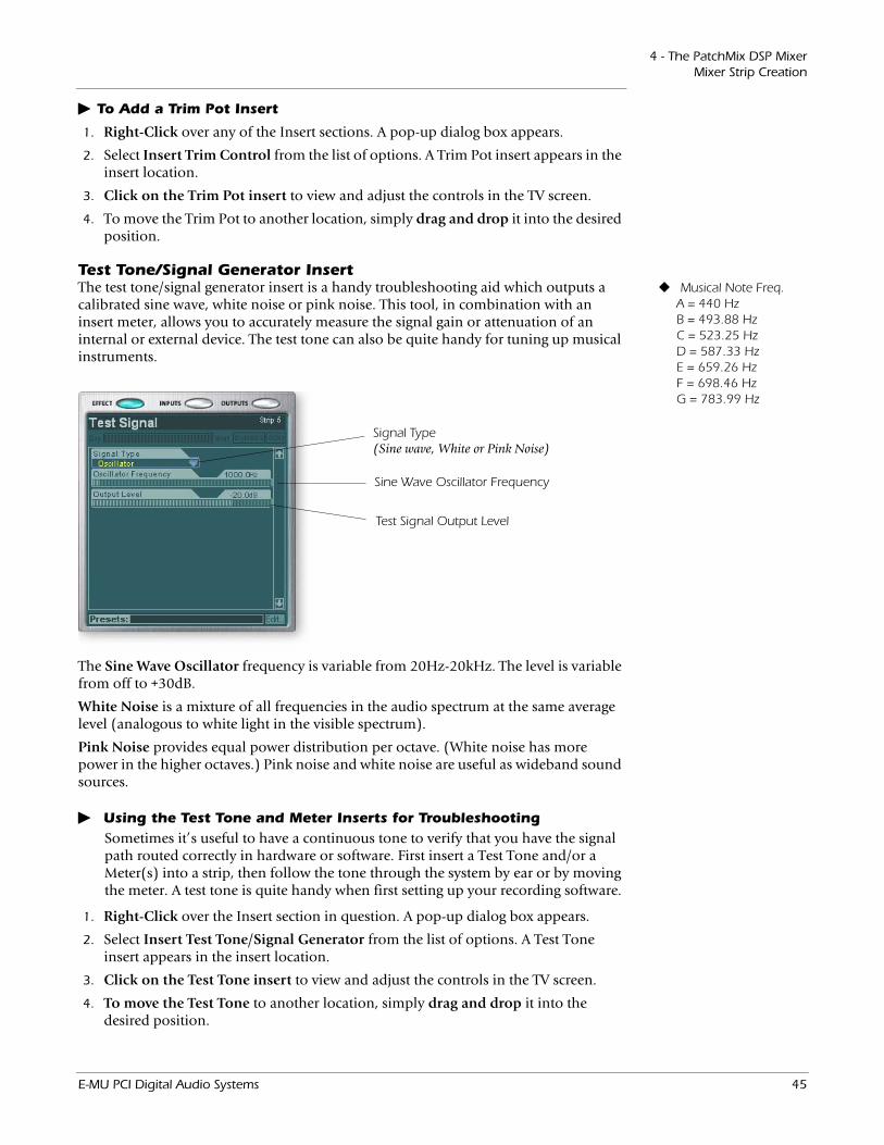
4 - The PatchMix DSP MixerMixer Strip Creation
To Add a Trim Pot Insert
1. Right-Click over any of the Insert sections. A pop-up dialog box appears.
2. Select Insert Trim Control from the list of options. A Trim Pot insert appears in the insert location.
3. Click on the Trim Pot insert to view and adjust the controls in the TV screen.
4. To move the Trim Pot to another location, simply drag and drop it into the desired position.
Test Tone/Signal Generator Insert Musical Note Freq. A = 440 Hz B = 493.88 Hz C = 523.25 Hz D = 587.33 Hz E = 659.26 Hz F = 698.46 Hz G = 783.99 Hz
The test tone/signal generator insert is a handy troubleshooting aid which outputs a calibrated sine wave, white noise or pink noise. This tool, in combination with an insert meter, allows you to accurately measure the signal gain or attenuation of an internal or external device. The test tone can also be quite handy for tuning up musical instruments.
Signal Type (Sine wave, White or Pink Noise)
Sine Wave Oscillator Frequency
Test Signal Output Level
The Sine Wave Oscillator frequency is variable from 20Hz-20kHz. The level is variable from off to +30dB.
White Noise is a mixture of all frequencies in the audio spectrum at the same average level (analogous to white light in the visible spectrum).
Pink Noise provides equal power distribution per octave. (White noise has more power in the higher octaves.) Pink noise and white noise are useful as wideband sound sources.
Using the Test Tone and Meter Inserts for TroubleshootingSometimes it’s useful to have a continuous tone to verify that you have the signal path routed correctly in hardware or software. First insert a Test Tone and/or a Meter(s) into a strip, then follow the tone through the system by ear or by moving the meter. A test tone is quite handy when first setting up your recording software.
1. Right-Click over the Insert section in question. A pop-up dialog box appears.
2. Select Insert Test Tone/Signal Generator from the list of options. A Test Tone insert appears in the insert location.
3. Click on the Test Tone insert to view and adjust the controls in the TV screen.
4. To move the Test Tone to another location, simply drag and drop it into the desired position.
E-MU PCI Digital Audio Systems 45
4 - The PatchMix DSP MixerMixer Strip Creation
Managing Your Inserts
To Delete an Insert:Tip: Select the Insert
and press the Delete key to delete the plug-in from the strip.
1. Right-Click over the Insert you wish to delete. A yellow line around the insert location indicates that it is selected. A pop-up dialog box appears.
2. Select Delete Insert to remove the selected insert or select Delete All Inserts to remove all inserts.
3. The insert(s) are deleted from the insert chain.
To Bypass an Insert:Inserts can be bypassed if you want to temporarily hear the audio without the effect or insert. Bypass can also be used to turn off a Send Insert.
Method #1
1. Click on the Effect (in the Insert section) and select Effect in the TV display.
2. Click the Bypass button.
Method #2
1. Right-Click over the Effect you want to bypass (in the Insert section). A pop-up dialog box appears.
2. Select Bypass Insert from the list of options.
To Bypass All Inserts:All Inserts in a strip can also be bypassed with a single command.
1. Right-Click over the Effect you want to bypass (in the Insert section). A pop-up dialog box appears.
2. Select Bypass All Inserts from the list of options.
To Solo an Insert:Inserts can also be soloed. Solo bypasses all the other inserts in the strip and allows you to hear only the soloed effect. This feature is very useful when adjusting the effect parameters.
Method #1
1. Click on the Effect (in the Insert section) and select Effect in the TV display.
2. Click the Solo button.
Method #2
1. Right-Click over the Effect you want to Solo (in the Insert section). A pop-up dialog box appears.
2. Select Solo Insert from the list of options.
46 Creative Professional
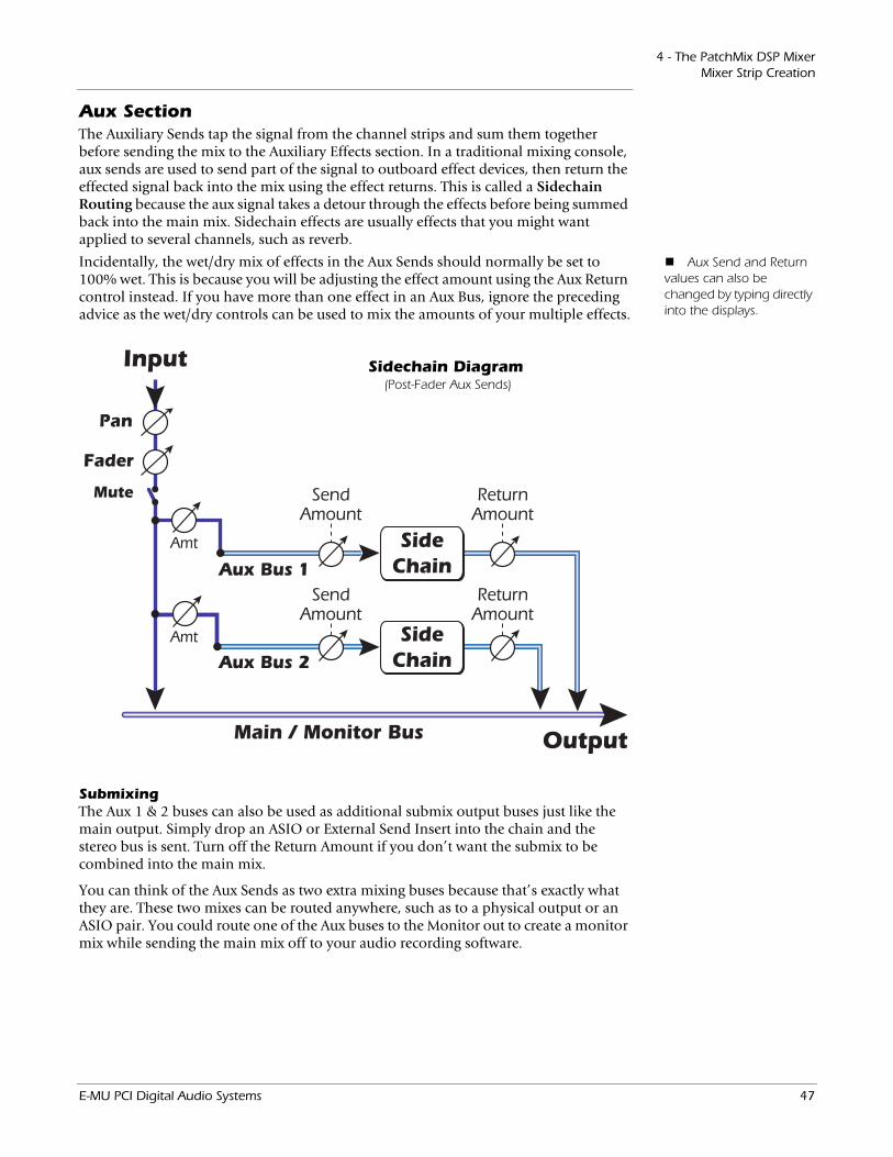
4 - The PatchMix DSP MixerMixer Strip Creation
Aux SectionThe Auxiliary Sends tap the signal from the channel strips and sum them together before sending the mix to the Auxiliary Effects section. In a traditional mixing console, aux sends are used to send part of the signal to outboard effect devices, then return the effected signal back into the mix using the effect returns. This is called a Sidechain Routing because the aux signal takes a detour through the effects before being summed back into the main mix. Sidechain effects are usually effects that you might want applied to several channels, such as reverb.
Aux Send and Return values can also be changed by typing directly into the displays.
Incidentally, the wet/dry mix of effects in the Aux Sends should normally be set to 100% wet. This is because you will be adjusting the effect amount using the Aux Return control instead. If you have more than one effect in an Aux Bus, ignore the preceding advice as the wet/dry controls can be used to mix the amounts of your multiple effects.
Main / Monitor Bus
SideChain
Output
ReturnAmount
SendAmount
Input
Amt
Amt
Aux Bus 1
Pan
Fader
Mute
SideChain
ReturnAmount
SendAmount
Aux Bus 2
Sidechain Diagram(Post-Fader Aux Sends)
SubmixingThe Aux 1 & 2 buses can also be used as additional submix output buses just like the main output. Simply drop an ASIO or External Send Insert into the chain and the stereo bus is sent. Turn off the Return Amount if you don’t want the submix to be combined into the main mix.
You can think of the Aux Sends as two extra mixing buses because that’s exactly what they are. These two mixes can be routed anywhere, such as to a physical output or an ASIO pair. You could route one of the Aux buses to the Monitor out to create a monitor mix while sending the main mix off to your audio recording software.
E-MU PCI Digital Audio Systems 47

4 - The PatchMix DSP MixerMixer Strip Creation
Pre or Post Fader Aux SendsWhen you create a New Mixer Strip you have the option to place both Aux Sends after the channel volume fader and mute control or you can place them before the fader and mute. Post-Fader turns down the send level as you lower the volume of the strip. With Pre-Fader selected, you may still hear the effected signal returning from one of the Aux Buses with the volume fader turned down.
With the Pre-Fader box selected, the Aux Send levels are completely unaffected by the Level Fader and Mute settings. The Pre-Fader setting allows you to create two completely different mixes using the Aux Buses since the signal levels of this mix won’t be affected by the fader settings.
Main / Monitor Bus
SideChain
Output
ReturnAmount
SendAmount
Input
Amt
Amt
Aux Bus 1
Pan
Fader
Mute
SideChain
ReturnAmount
SendAmount
Aux Bus 2
Main / Monitor Bus
SideChain
Output
ReturnAmount
SendAmount
Input
Amt
Mute
Amt
Aux Bus 1
Pan
Fader
SideChain
ReturnAmount
SendAmount
Aux Bus 2
Pre-Fader Aux SendVolume Fader & Mute does NOT affect Send Levels
Post-Fader Aux SendVolume Fader & Mute affects both Aux Send Levels
In order to change a strip from pre-fader to post-fader or vice-versa, you have to delete the strip and create a new one.
48 Creative Professional
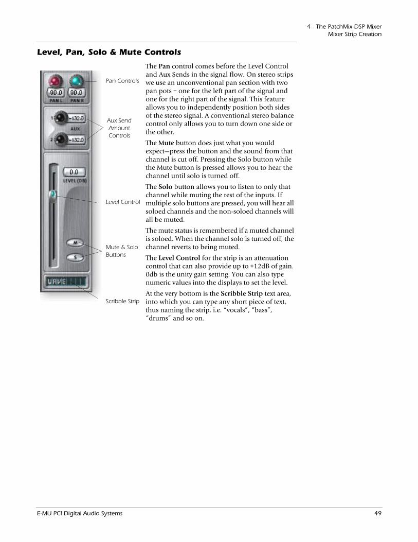
4 - The PatchMix DSP MixerMixer Strip Creation
Level, Pan, Solo & Mute Controls
Level Control
Pan Controls
Mute & Solo Buttons
Aux Send Amount Controls
Scribble Strip
The Pan control comes before the Level Control and Aux Sends in the signal flow. On stereo strips we use an unconventional pan section with two pan pots – one for the left part of the signal and one for the right part of the signal. This feature allows you to independently position both sides of the stereo signal. A conventional stereo balance control only allows you to turn down one side or the other.
The Mute button does just what you would expect—press the button and the sound from that channel is cut off. Pressing the Solo button while the Mute button is pressed allows you to hear the channel until solo is turned off.
The Solo button allows you to listen to only that channel while muting the rest of the inputs. If multiple solo buttons are pressed, you will hear all soloed channels and the non-soloed channels will all be muted.
The mute status is remembered if a muted channel is soloed. When the channel solo is turned off, the channel reverts to being muted.
The Level Control for the strip is an attenuation control that can also provide up to +12dB of gain. 0db is the unity gain setting. You can also type numeric values into the displays to set the level.
At the very bottom is the Scribble Strip text area, into which you can type any short piece of text, thus naming the strip, i.e. “vocals”, “bass”, “drums” and so on.
E-MU PCI Digital Audio Systems 49
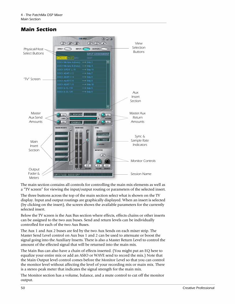
4 - The PatchMix DSP MixerMain Section
Main Section
View Selection Buttons
Aux Insert
Section
Output Fader & Meters
Sync &Sample Rate Indicators
“TV” Screen
Master Aux Send Amounts
Master Aux Return
Amounts
Physical/Host Select Buttons
Main Insert
Section
Monitor Controls
Session Name
The main section contains all controls for controlling the main mix elements as well as a “TV screen” for viewing the input/output routing or parameters of the selected insert.
The three buttons across the top of the main section select what is shown on the TV display. Input and output routings are graphically displayed. When an insert is selected (by clicking on the insert), the screen shows the available parameters for the currently selected insert.
Below the TV screen is the Aux Bus section where effects, effects chains or other inserts can be assigned to the two aux buses. Send and return levels can be individually controlled for each of the two Aux Buses.
The Aux 1 and Aux 2 buses are fed by the two Aux Sends on each mixer strip. The Master Send Level control on Aux bus 1 and 2 can be used to attenuate or boost the signal going into the Auxiliary Inserts. There is also a Master Return Level to control the amount of the effected signal that will be returned into the main mix.
The Main Bus can also have a chain of effects inserted. (You might put an EQ here to equalize your entire mix or add an ASIO or WAVE send to record the mix.) Note that the Main Output level control comes before the Monitor Level so that you can control the monitor level without affecting the level of your recording mix or main mix. There is a stereo peak meter that indicates the signal strength for the main mix.
The Monitor section has a volume, balance, and a mute control to cut off the monitor output.
50 Creative Professional
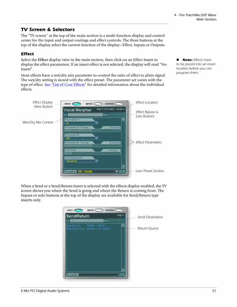
4 - The PatchMix DSP MixerMain Section
TV Screen & SelectorsThe “TV screen” at the top of the main section is a multi-function display and control center for the input and output routings and effect controls. The three buttons at the top of the display select the current function of the display—Effect, Inputs or Outputs.
Effect Note: Effects have
to be placed into an insert location before you can program them.
Select the Effect display view in the main section, then click on an Effect Insert to display the effect parameters. If an insert effect is not selected, the display will read “No Insert”.
Most effects have a wet/dry mix parameter to control the ratio of effect to plain signal. The wet/dry setting is stored with the effect preset. The parameter set varies with the type of effect. See “List of Core Effects” for detailed information about the individual effects.
Effect Display View Button
Effect Location
Wet/Dry Mix Control
Effect Parameters
Effect Bypass & Solo Buttons
User Preset Section
Send Destination
Return Source
When a Send or a Send/Return insert is selected with the effects display enabled, the TV screen shows you where the Send is going and where the Return is coming from. The bypass or solo buttons at the top of the display are available for Send/Return type inserts only.
E-MU PCI Digital Audio Systems 51
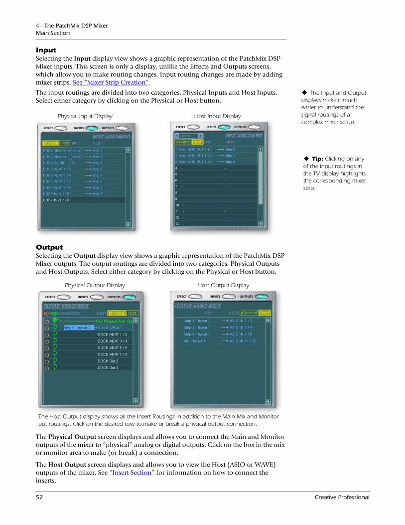
4 - The PatchMix DSP MixerMain Section
InputSelecting the Input display view shows a graphic representation of the PatchMix DSP Mixer inputs. This screen is only a display, unlike the Effects and Outputs screens, which allow you to make routing changes. Input routing changes are made by adding mixer strips. See “Mixer Strip Creation”.
The Input and Output displays make it much easier to understand the signal routings of a complex mixer setup.
The input routings are divided into two categories: Physical Inputs and Host Inputs. Select either category by clicking on the Physical or Host button.
Tip: Clicking on any of the input routings in the TV display highlights the corresponding mixer strip.
Physical Input Display Host Input Display
OutputSelecting the Output display view shows a graphic representation of the PatchMix DSP Mixer outputs. The output routings are divided into two categories: Physical Outputs and Host Outputs. Select either category by clicking on the Physical or Host button.
Physical Output Display Host Output Display
The Host Output display shows all the Insert Routings in addition to the Main Mix and Monitor out routings. Click on the desired row to make or break a physical output connection.
The Physical Output screen displays and allows you to connect the Main and Monitor outputs of the mixer to “physical” analog or digital outputs. Click on the box in the mix or monitor area to make (or break) a connection.
The Host Output screen displays and allows you to view the Host (ASIO or WAVE) outputs of the mixer. See “Insert Section” for information on how to connect the inserts.
52 Creative Professional
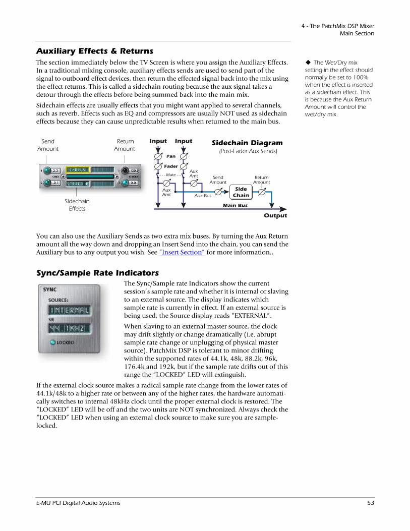
4 - The PatchMix DSP MixerMain Section
Auxiliary Effects & ReturnsThe Wet/Dry mix
setting in the effect should normally be set to 100% when the effect is inserted as a sidechain effect. This is because the Aux Return Amount will control the wet/dry mix.
The section immediately below the TV Screen is where you assign the Auxiliary Effects. In a traditional mixing console, auxiliary effects sends are used to send part of the signal to outboard effect devices, then return the effected signal back into the mix using the effect returns. This is called a sidechain routing because the aux signal takes a detour through the effects before being summed back into the main mix.
Sidechain effects are usually effects that you might want applied to several channels, such as reverb. Effects such as EQ and compressors are usually NOT used as sidechain effects because they can cause unpredictable results when returned to the main bus.
Main Bus
SideChain
Input
Fader
Mute
Output
ReturnAmount
SendAmount
Input
Pan
AuxAmt
AuxAmt
Aux Bus
Sidechain Diagram(Post-Fader Aux Sends)
Send Amount
Sidechain Effects
ReturnAmount
You can also use the Auxiliary Sends as two extra mix buses. By turning the Aux Return amount all the way down and dropping an Insert Send into the chain, you can send the Auxiliary bus to any output you wish. See “Insert Section” for more information.‚
Sync/Sample Rate IndicatorsThe Sync/Sample rate Indicators show the current session’s sample rate and whether it is internal or slaving to an external source. The display indicates which sample rate is currently in effect. If an external source is being used, the Source display reads “EXTERNAL”.
When slaving to an external master source, the clock may drift slightly or change dramatically (i.e. abrupt sample rate change or unplugging of physical master source). PatchMix DSP is tolerant to minor drifting within the supported rates of 44.1k, 48k, 88.2k, 96k, 176.4k and 192k, but if the sample rate drifts out of this range the “LOCKED” LED will extinguish.
If the external clock source makes a radical sample rate change from the lower rates of 44.1k/48k to a higher rate or between any of the higher rates, the hardware automati-cally switches to internal 48kHz clock until the proper external clock is restored. The “LOCKED” LED will be off and the two units are NOT synchronized. Always check the “LOCKED” LED when using an external clock source to make sure you are sample-locked.
E-MU PCI Digital Audio Systems 53
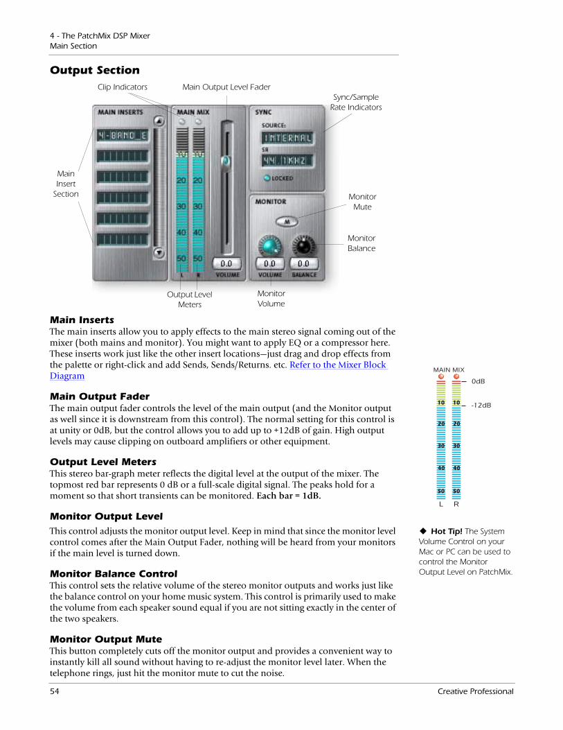
4 - The PatchMix DSP MixerMain Section
Output Section
MainInsert
Section
Output Level Meters
Main Output Level Fader
Monitor Mute
Monitor Volume
Monitor Balance
Sync/Sample Rate Indicators
Clip Indicators
Main InsertsThe main inserts allow you to apply effects to the main stereo signal coming out of the mixer (both mains and monitor). You might want to apply EQ or a compressor here. These inserts work just like the other insert locations—just drag and drop effects from the palette or right-click and add Sends, Sends/Returns. etc. Refer to the Mixer Block Diagram
Main Output FaderThe main output fader controls the level of the main output (and the Monitor output as well since it is downstream from this control). The normal setting for this control is at unity or 0dB, but the control allows you to add up to +12dB of gain. High output levels may cause clipping on outboard amplifiers or other equipment.
Output Level MetersThis stereo bar-graph meter reflects the digital level at the output of the mixer. The topmost red bar represents 0 dB or a full-scale digital signal. The peaks hold for a moment so that short transients can be monitored. Each bar = 1dB.
Monitor Output LevelHot Tip! The System
Volume Control on your Mac or PC can be used to control the Monitor Output Level on PatchMix.
This control adjusts the monitor output level. Keep in mind that since the monitor level control comes after the Main Output Fader, nothing will be heard from your monitors if the main level is turned down.
Monitor Balance ControlThis control sets the relative volume of the stereo monitor outputs and works just like the balance control on your home music system. This control is primarily used to make the volume from each speaker sound equal if you are not sitting exactly in the center of the two speakers.
Monitor Output MuteThis button completely cuts off the monitor output and provides a convenient way to instantly kill all sound without having to re-adjust the monitor level later. When the telephone rings, just hit the monitor mute to cut the noise.
L R
MAIN MIX
-12dB
0dB
10
20
30
40
50
10
20
30
40
50
54 Creative Professional
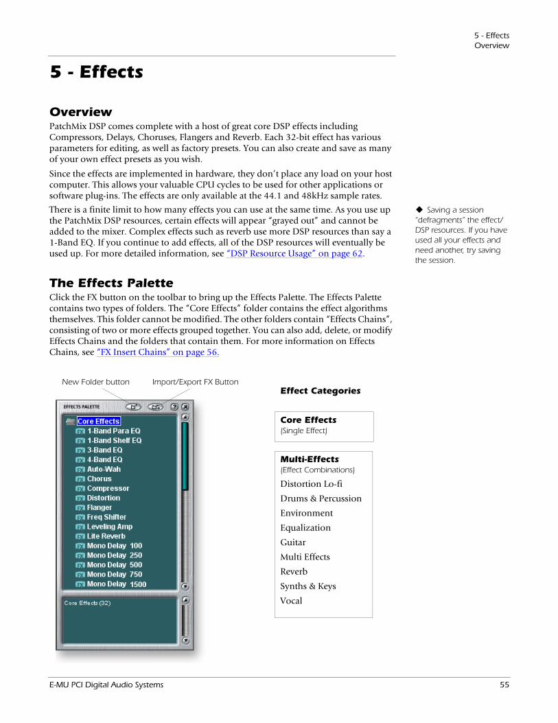
5 - EffectsOverview
5 - Effects
OverviewPatchMix DSP comes complete with a host of great core DSP effects including Compressors, Delays, Choruses, Flangers and Reverb. Each 32-bit effect has various parameters for editing, as well as factory presets. You can also create and save as many of your own effect presets as you wish.
Since the effects are implemented in hardware, they don’t place any load on your host computer. This allows your valuable CPU cycles to be used for other applications or software plug-ins. The effects are only available at the 44.1 and 48kHz sample rates.
Saving a session “defragments” the effect/DSP resources. If you have used all your effects and need another, try saving the session.
There is a finite limit to how many effects you can use at the same time. As you use up the PatchMix DSP resources, certain effects will appear “grayed out” and cannot be added to the mixer. Complex effects such as reverb use more DSP resources than say a 1-Band EQ. If you continue to add effects, all of the DSP resources will eventually be used up. For more detailed information, see “DSP Resource Usage” on page 62.
The Effects PaletteClick the FX button on the toolbar to bring up the Effects Palette. The Effects Palette contains two types of folders. The “Core Effects” folder contains the effect algorithms themselves. This folder cannot be modified. The other folders contain “Effects Chains”, consisting of two or more effects grouped together. You can also add, delete, or modify Effects Chains and the folders that contain them. For more information on Effects Chains, see “FX Insert Chains” on page 56.
Effect Categories
Core Effects (Single Effect)
Multi-Effects (Effect Combinations)
Distortion Lo-fi
Drums & Percussion
Environment
Equalization
Guitar
Multi Effects
Reverb
Synths & Keys
Vocal
New Folder button Import/Export FX Button
E-MU PCI Digital Audio Systems 55
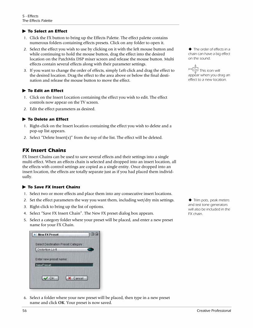
5 - EffectsThe Effects Palette
To Select an Effect
1. Click the FX button to bring up the Effects Palette. The effect palette contains numerous folders containing effects presets. Click on any folder to open it.
The order of effects in a chain can have a big effect on the sound.
2. Select the effect you wish to use by clicking on it with the left mouse button and while continuing to hold the mouse button, drag the effect into the desired location on the PatchMix DSP mixer screen and release the mouse button. Multi effects contain several effects along with their parameter settings.
This icon will appear when you drag an effect to a new location.
3. If you want to change the order of effects, simply Left-click and drag the effect to the desired location. Drag the effect to the area above or below the final desti-nation and release the mouse button to move the effect.
To Edit an Effect
1. Click on the Insert Location containing the effect you wish to edit. The effect controls now appear on the TV screen.
2. Edit the effect parameters as desired.
To Delete an Effect
1. Right-click on the Insert location containing the effect you wish to delete and a pop-up list appears.
2. Select “Delete Insert(s)” from the top of the list. The effect will be deleted.
FX Insert ChainsFX Insert Chains can be used to save several effects and their settings into a single multi-effect. When an effects chain is selected and dropped into an insert location, all the effects with control settings are copied as a single entity. Once dropped into an insert location, the effects are totally separate just as if you had placed them individ-ually.
To Save FX Insert Chains
1. Select two or more effects and place them into any consecutive insert locations.
Trim pots, peak meters and test tone generators will also be included in the FX chain.
2. Set the effect parameters the way you want them, including wet/dry mix settings.
3. Right-click to bring up the list of options.
4. Select “Save FX Insert Chain”. The New FX preset dialog box appears.
5. Select a category folder where your preset will be placed, and enter a new preset name for your FX Chain.
6. Select a folder where your new preset will be placed, then type in a new preset name and click OK. Your preset is now saved.
56 Creative Professional
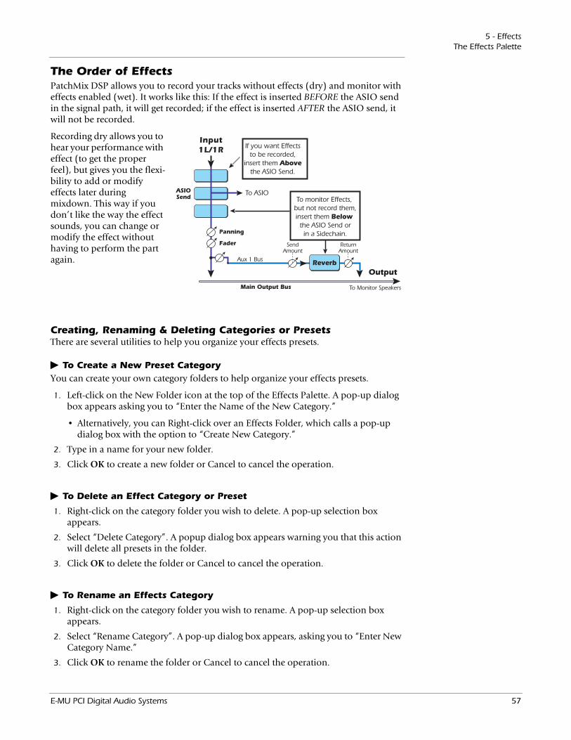
5 - EffectsThe Effects Palette
The Order of EffectsPatchMix DSP allows you to record your tracks without effects (dry) and monitor with effects enabled (wet). It works like this: If the effect is inserted BEFORE the ASIO send in the signal path, it will get recorded; if the effect is inserted AFTER the ASIO send, it will not be recorded.
Recording dry allows you to hear your performance with effect (to get the proper feel), but gives you the flexi-bility to add or modify effects later during mixdown. This way if you don’t like the way the effect sounds, you can change or modify the effect without having to perform the part again.
Creating, Renaming & Deleting Categories or PresetsThere are several utilities to help you organize your effects presets.
To Create a New Preset CategoryYou can create your own category folders to help organize your effects presets.
1. Left-click on the New Folder icon at the top of the Effects Palette. A pop-up dialog box appears asking you to “Enter the Name of the New Category.”
• Alternatively, you can Right-click over an Effects Folder, which calls a pop-up dialog box with the option to “Create New Category.”
2. Type in a name for your new folder.
3. Click OK to create a new folder or Cancel to cancel the operation.
To Delete an Effect Category or Preset
1. Right-click on the category folder you wish to delete. A pop-up selection box appears.
2. Select “Delete Category”. A popup dialog box appears warning you that this action will delete all presets in the folder.
3. Click OK to delete the folder or Cancel to cancel the operation.
To Rename an Effects Category
1. Right-click on the category folder you wish to rename. A pop-up selection box appears.
2. Select “Rename Category”. A pop-up dialog box appears, asking you to “Enter New Category Name.”
3. Click OK to rename the folder or Cancel to cancel the operation.
OutputReverb
ReturnAmount
To Monitor Speakers
SendAmount
Aux 1 Bus
ASIOSend
Input1L/1R
Fader
Panning
Main Output Bus
To ASIO
If you want Effectsto be recorded,
insert them Abovethe ASIO Send.
To monitor Effects, but not record them,insert them Below
the ASIO Send orin a Sidechain.
E-MU PCI Digital Audio Systems 57
5 - EffectsThe Effects Palette
Importing and Exporting Core FX Presets and FX Insert ChainsThese utilities make it easy to import or export your FX Presets and FX Insert Chains. You can share presets with your friends or download new presets from the Internet.
To Import Core FX PresetsThis option imports complete folders of Core FX presets into the E-MU PatchMix DSP folder (normally located here: “C:\Program Files\Creative Professional\E-MU PatchMix DSP\Core Effects”). If the name of an imported FX preset exactly matches a preset you already have, a number will be appended to end of the imported preset name.
1. Click the Import/Export FX Library button from the FX Palette.
2. Select Import FX Library. The “Browse for Folder” window appears.
3. Choose the folder where the Core FX presets you wish to import are located.
4. The selected folder of Core FX presets will be copied into the Core Effects folder of PatchMix DSP.
To Import FX Category FoldersThis option imports complete category folders of FX Chains into the E-MU PatchMix DSP folder (normally located here: “C:\Program Files\Creative Professional\E-MU PatchMix DSP\Effect Presets”). If the name of an imported FX preset exactly matches a preset you already have, a number will be appended to end of the imported preset name.
1. Click the Import/Export FX Library button from the FX Palette.
2. Select Import FX Category. The “Browse for Folder” window appears.
3. Choose the folder where the FX Chains you wish to import are located.
4. The selected folder of FX Chains will be copied into the Effect Presets folder of PatchMix DSP.
To Export your Core FX PresetsThis option exports your Core FX presets to a folder of your choice.
1. Click the Import/Export FX Library button from the FX Palette.
2. Select Export FX Library. The “Browse for Folder” window appears.
3. Choose a destination location for the Core FX presets, then press OK.
4. The Core FX presets will be copied to the selected destination.
To Export your FX Category Folders
This option exports a single category of FX chains to a folder of your choice.
1. Click the Import/Export FX Library button from the FX Palette.
2. Select Export FX Category. A pop-up dialog box appears asking you to “Choose the FX Category to be exported”.
3. Choose the desired FX Category to export. Press OK to continue or Cancel to cancel the operation.
4. The “Browse for Folder” window appears. Choose a destination location for the Core FX presets, then press OK.
5. The FX Chains will be copied to the selected destination.
58 Creative Professional
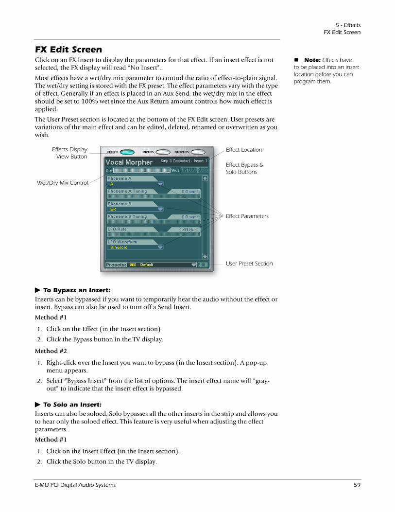
5 - EffectsFX Edit Screen
FX Edit Screen Note: Effects have
to be placed into an insert location before you can program them.
Click on an FX Insert to display the parameters for that effect. If an insert effect is not selected, the FX display will read “No Insert”.
Most effects have a wet/dry mix parameter to control the ratio of effect-to-plain signal. The wet/dry setting is stored with the FX preset. The effect parameters vary with the type of effect. Generally if an effect is placed in an Aux Send, the wet/dry mix in the effect should be set to 100% wet since the Aux Return amount controls how much effect is applied.
The User Preset section is located at the bottom of the FX Edit screen. User presets are variations of the main effect and can be edited, deleted, renamed or overwritten as you wish.
Effects Display View Button
Effect Location
Wet/Dry Mix Control
Effect Parameters
Effect Bypass & Solo Buttons
User Preset Section
To Bypass an Insert:Inserts can be bypassed if you want to temporarily hear the audio without the effect or insert. Bypass can also be used to turn off a Send Insert.
Method #1
1. Click on the Effect (in the Insert section)
2. Click the Bypass button in the TV display.
Method #2
1. Right-click over the Insert you want to bypass (in the Insert section). A pop-up menu appears.
2. Select “Bypass Insert” from the list of options. The insert effect name will “gray-out” to indicate that the insert effect is bypassed.
To Solo an Insert:Inserts can also be soloed. Solo bypasses all the other inserts in the strip and allows you to hear only the soloed effect. This feature is very useful when adjusting the effect parameters.
Method #1
1. Click on the Insert Effect (in the Insert section).
2. Click the Solo button in the TV display.
E-MU PCI Digital Audio Systems 59
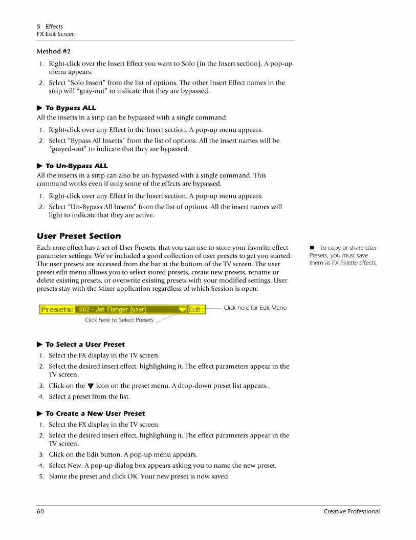
5 - EffectsFX Edit Screen
Method #2
1. Right-click over the Insert Effect you want to Solo (in the Insert section). A pop-up menu appears.
2. Select “Solo Insert” from the list of options. The other Insert Effect names in the strip will “gray-out” to indicate that they are bypassed.
To Bypass ALLAll the inserts in a strip can be bypassed with a single command.
1. Right-click over any Effect in the Insert section. A pop-up menu appears.
2. Select “Bypass All Inserts” from the list of options. All the insert names will be “grayed-out” to indicate that they are bypassed.
To Un-Bypass ALLAll the inserts in a strip can also be un-bypassed with a single command. This command works even if only some of the effects are bypassed.
1. Right-click over any Effect in the Insert section. A pop-up menu appears.
2. Select “Un-Bypass All Inserts” from the list of options. All the insert names will light to indicate that they are active.
User Preset Section To copy or share User
Presets, you must save them as FX Palette effects.
Each core effect has a set of User Presets, that you can use to store your favorite effect parameter settings. We’ve included a good collection of user presets to get you started. The user presets are accessed from the bar at the bottom of the TV screen. The user preset edit menu allows you to select stored presets, create new presets, rename or delete existing presets, or overwrite existing presets with your modified settings. User presets stay with the Mixer application regardless of which Session is open.
Click here for Edit Menu
Click here to Select Presets
To Select a User Preset
1. Select the FX display in the TV screen.
2. Select the desired insert effect, highlighting it. The effect parameters appear in the TV screen.
3. Click on the icon on the preset menu. A drop-down preset list appears.
4. Select a preset from the list.
To Create a New User Preset
1. Select the FX display in the TV screen.
2. Select the desired insert effect, highlighting it. The effect parameters appear in the TV screen.
3. Click on the Edit button. A pop-up menu appears.
4. Select New. A pop-up dialog box appears asking you to name the new preset.
5. Name the preset and click OK. Your new preset is now saved.
60 Creative Professional
5 - EffectsFX Edit Screen
To Delete a User Preset
1. Select the user preset you wish to delete from the user preset menu.
2. Click on the Edit button. A pop-up menu appears.
3. Select Delete. A pop-up dialog box appears asking you to confirm your action.
4. Click OK to delete the preset or No or Cancel to cancel the operation.
To Rename a User Preset
1. Select the user preset you wish to rename from the user preset menu.
2. Click on the Edit button. A pop-up menu appears.
3. Select Rename. A pop-up dialog box appears asking you to rename the preset.
4. Type in the new preset name, then click OK to rename the preset or Cancel to cancel the operation.
To Overwrite or Save a User PresetThis operation allows you to overwrite an existing preset with a newer version.
1. Select the user preset you wish to modify from the user preset menu and make any changes you wish.
2. Click on the Edit button. A pop-up menu appears.
3. Select Overwrite/Save. The current preset will be overwritten with the new settings.
Core Effects and Effects PresetsHint: You can open
the effects presets with “NotePad” or other word processor to view and edit the name and parameters.
The Core Effects cannot be removed or copied. Effect presets (stored in “C:\Program Files\Creative Professional\E-MU 1616\E-MU PatchMix DSP\Effect Presets”) can be copied, e-mailed or shared like any other computer file.
E-MU PCI Digital Audio Systems 61
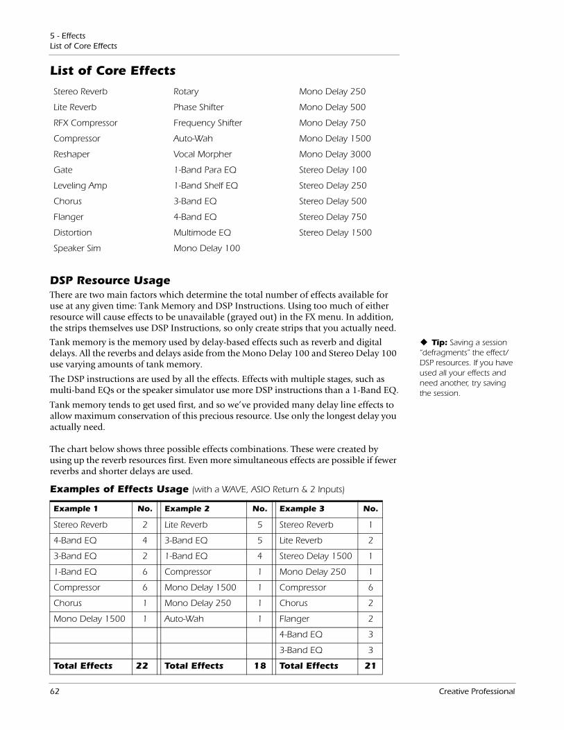
5 - EffectsList of Core Effects
List of Core Effects
Stereo Reverb Rotary Mono Delay 250
Lite Reverb Phase Shifter Mono Delay 500
RFX Compressor Frequency Shifter Mono Delay 750
Compressor Auto-Wah Mono Delay 1500
Reshaper Vocal Morpher Mono Delay 3000
Gate 1-Band Para EQ Stereo Delay 100
Leveling Amp 1-Band Shelf EQ Stereo Delay 250
Chorus 3-Band EQ Stereo Delay 500
Flanger 4-Band EQ Stereo Delay 750
Distortion Multimode EQ Stereo Delay 1500
Speaker Sim Mono Delay 100
DSP Resource UsageThere are two main factors which determine the total number of effects available for use at any given time: Tank Memory and DSP Instructions. Using too much of either resource will cause effects to be unavailable (grayed out) in the FX menu. In addition, the strips themselves use DSP Instructions, so only create strips that you actually need.
Tip: Saving a session “defragments” the effect/DSP resources. If you have used all your effects and need another, try saving the session.
Tank memory is the memory used by delay-based effects such as reverb and digital delays. All the reverbs and delays aside from the Mono Delay 100 and Stereo Delay 100 use varying amounts of tank memory.
The DSP instructions are used by all the effects. Effects with multiple stages, such as multi-band EQs or the speaker simulator use more DSP instructions than a 1-Band EQ.
Tank memory tends to get used first, and so we’ve provided many delay line effects to allow maximum conservation of this precious resource. Use only the longest delay you actually need.
The chart below shows three possible effects combinations. These were created by using up the reverb resources first. Even more simultaneous effects are possible if fewer reverbs and shorter delays are used.
Examples of Effects Usage (with a WAVE, ASIO Return & 2 Inputs)
Example 1 No. Example 2 No. Example 3 No.
Stereo Reverb 2 Lite Reverb 5 Stereo Reverb 1
4-Band EQ 4 3-Band EQ 5 Lite Reverb 2
3-Band EQ 2 1-Band EQ 4 Stereo Delay 1500 1
1-Band EQ 6 Compressor 1 Mono Delay 250 1
Compressor 6 Mono Delay 1500 1 Compressor 6
Chorus 1 Mono Delay 250 1 Chorus 2
Mono Delay 1500 1 Auto-Wah 1 Flanger 2
4-Band EQ 3
3-Band EQ 3
Total Effects 22 Total Effects 18 Total Effects 21
62 Creative Professional
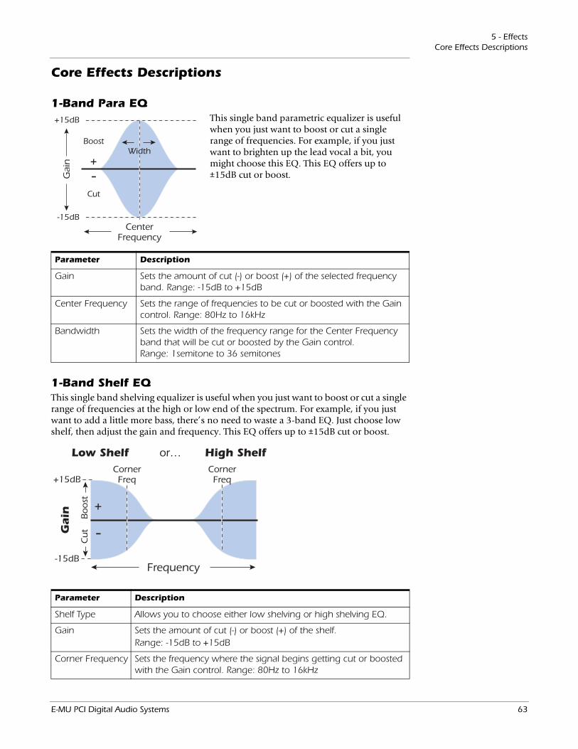
5 - EffectsCore Effects Descriptions
Core Effects Descriptions
1-Band Para EQThis single band parametric equalizer is useful when you just want to boost or cut a single range of frequencies. For example, if you just want to brighten up the lead vocal a bit, you might choose this EQ. This EQ offers up to ±15dB cut or boost.
CenterFrequency
Boost
Gai
n
Cut
-+
+15dB
-15dB
Width
Parameter Description
Gain Sets the amount of cut (-) or boost (+) of the selected frequency band. Range: -15dB to +15dB
Center Frequency Sets the range of frequencies to be cut or boosted with the Gain control. Range: 80Hz to 16kHz
Bandwidth Sets the width of the frequency range for the Center Frequency band that will be cut or boosted by the Gain control. Range: 1semitone to 36 semitones
1-Band Shelf EQThis single band shelving equalizer is useful when you just want to boost or cut a single range of frequencies at the high or low end of the spectrum. For example, if you just want to add a little more bass, there’s no need to waste a 3-band EQ. Just choose low shelf, then adjust the gain and frequency. This EQ offers up to ±15dB cut or boost.
Frequency
Low Shelf or… High Shelf
Boost
Gain
Cut
CornerFreq
CornerFreq
-
+
+15dB
-15dB
Parameter Description
Shelf Type Allows you to choose either low shelving or high shelving EQ.
Gain Sets the amount of cut (-) or boost (+) of the shelf.Range: -15dB to +15dB
Corner Frequency Sets the frequency where the signal begins getting cut or boosted with the Gain control. Range: 80Hz to 16kHz
E-MU PCI Digital Audio Systems 63
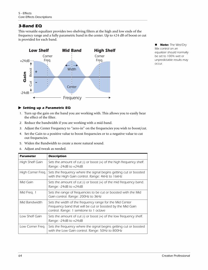
5 - EffectsCore Effects Descriptions
3-Band EQThis versatile equalizer provides two shelving filters at the high and low ends of the frequency range and a fully parametric band in the center. Up to ±24 dB of boost or cut is provided for each band.
Frequency
Low Shelf Mid Band High Shelf
Boost
Gain
Cut
CornerFreq.
CornerFreq.
-
+
Center
Width
+24dB
-24dB
Note: The Wet/Dry Mix control on an equalizer should normally be set to 100% wet or unpredictable results may occur.
Setting up a Parametric EQ
Parameter Description
High Shelf Gain Sets the amount of cut (-) or boost (+) of the high frequency shelf.Range: -24dB to +24dB
High Corner Freq. Sets the frequency where the signal begins getting cut or boosted with the High Gain control. Range: 4kHz to 16kHz
Mid Gain Sets the amount of cut (-) or boost (+) of the mid frequency band.Range: -24dB to +24dB
Mid Freq. 1 Sets the range of frequencies to be cut or boosted with the Mid Gain control. Range: 200Hz to 3kHz
Mid Bandwidth Sets the width of the frequency range for the Mid Center Frequency band that will be cut or boosted by the Mid Gain control. Range: 1 semitone to 1 octave
Low Shelf Gain Sets the amount of cut (-) or boost (+) of the low frequency shelf.Range: -24dB to +24dB
Low Corner Freq. Sets the frequency where the signal begins getting cut or boosted with the Low Gain control. Range: 50Hz to 800Hz
1. Turn up the gain on the band you are working with. This allows you to easily hear the effect of the filter.
2. Reduce the bandwidth if you are working with a mid-band.
3. Adjust the Center Frequency to “zero-in” on the frequencies you wish to boost/cut.
4. Set the Gain to a positive value to boost frequencies or to a negative value to cut out frequencies.
5. Widen the Bandwidth to create a more natural sound.
6. Adjust and tweak as needed.
64 Creative Professional
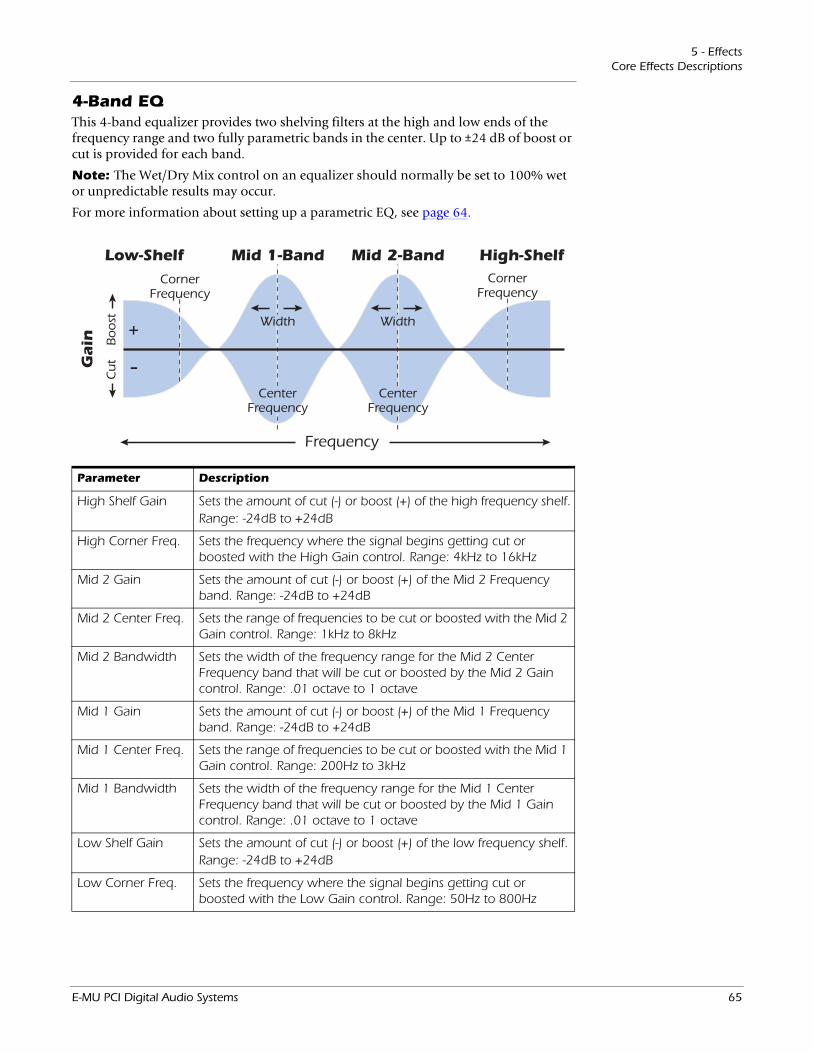
5 - EffectsCore Effects Descriptions
4-Band EQThis 4-band equalizer provides two shelving filters at the high and low ends of the frequency range and two fully parametric bands in the center. Up to ±24 dB of boost or cut is provided for each band.
Note: The Wet/Dry Mix control on an equalizer should normally be set to 100% wet or unpredictable results may occur.
For more information about setting up a parametric EQ, see page 64.
Frequency
Low-Shelf Mid 1-Band High-Shelf
Boost
Gain
Cut
CornerFrequency
CornerFrequency
-
+ Width
Mid 2-Band
Width
CenterFrequency
CenterFrequency
Parameter Description
High Shelf Gain Sets the amount of cut (-) or boost (+) of the high frequency shelf.Range: -24dB to +24dB
High Corner Freq. Sets the frequency where the signal begins getting cut or boosted with the High Gain control. Range: 4kHz to 16kHz
Mid 2 Gain Sets the amount of cut (-) or boost (+) of the Mid 2 Frequency band. Range: -24dB to +24dB
Mid 2 Center Freq. Sets the range of frequencies to be cut or boosted with the Mid 2 Gain control. Range: 1kHz to 8kHz
Mid 2 Bandwidth Sets the width of the frequency range for the Mid 2 Center Frequency band that will be cut or boosted by the Mid 2 Gain control. Range: .01 octave to 1 octave
Mid 1 Gain Sets the amount of cut (-) or boost (+) of the Mid 1 Frequency band. Range: -24dB to +24dB
Mid 1 Center Freq. Sets the range of frequencies to be cut or boosted with the Mid 1 Gain control. Range: 200Hz to 3kHz
Mid 1 Bandwidth Sets the width of the frequency range for the Mid 1 Center Frequency band that will be cut or boosted by the Mid 1 Gain control. Range: .01 octave to 1 octave
Low Shelf Gain Sets the amount of cut (-) or boost (+) of the low frequency shelf.Range: -24dB to +24dB
Low Corner Freq. Sets the frequency where the signal begins getting cut or boosted with the Low Gain control. Range: 50Hz to 800Hz
E-MU PCI Digital Audio Systems 65
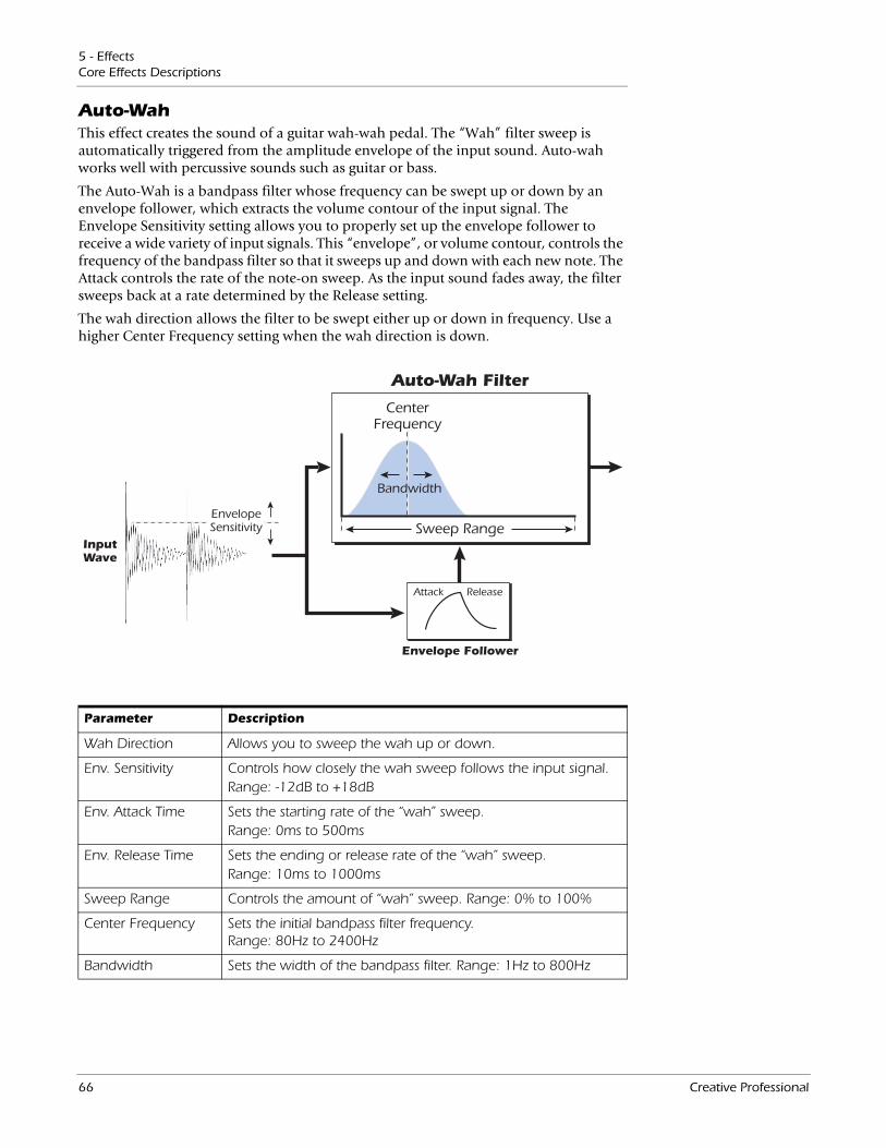
5 - EffectsCore Effects Descriptions
Auto-WahThis effect creates the sound of a guitar wah-wah pedal. The “Wah” filter sweep is automatically triggered from the amplitude envelope of the input sound. Auto-wah works well with percussive sounds such as guitar or bass.
The Auto-Wah is a bandpass filter whose frequency can be swept up or down by an envelope follower, which extracts the volume contour of the input signal. The Envelope Sensitivity setting allows you to properly set up the envelope follower to receive a wide variety of input signals. This “envelope”, or volume contour, controls the frequency of the bandpass filter so that it sweeps up and down with each new note. The Attack controls the rate of the note-on sweep. As the input sound fades away, the filter sweeps back at a rate determined by the Release setting.
The wah direction allows the filter to be swept either up or down in frequency. Use a higher Center Frequency setting when the wah direction is down.
CenterFrequency
Auto-Wah Filter
Attack Release
Sweep Range
Bandwidth
EnvelopeSensitivity
InputWave
Envelope Follower
Parameter Description
Wah Direction Allows you to sweep the wah up or down.
Env. Sensitivity Controls how closely the wah sweep follows the input signal.Range: -12dB to +18dB
Env. Attack Time Sets the starting rate of the “wah” sweep.Range: 0ms to 500ms
Env. Release Time Sets the ending or release rate of the “wah” sweep.Range: 10ms to 1000ms
Sweep Range Controls the amount of “wah” sweep. Range: 0% to 100%
Center Frequency Sets the initial bandpass filter frequency. Range: 80Hz to 2400Hz
Bandwidth Sets the width of the bandpass filter. Range: 1Hz to 800Hz
66 Creative Professional
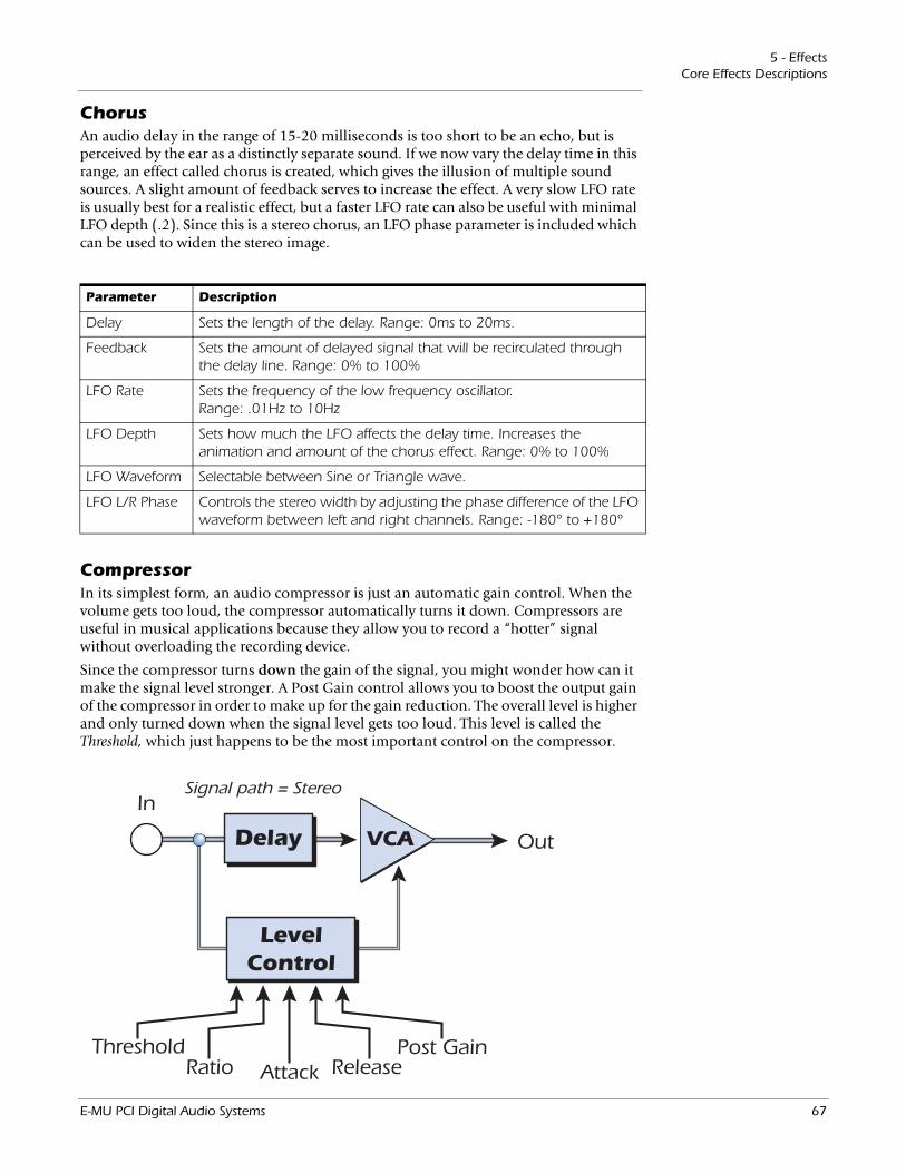
5 - EffectsCore Effects Descriptions
ChorusAn audio delay in the range of 15-20 milliseconds is too short to be an echo, but is perceived by the ear as a distinctly separate sound. If we now vary the delay time in this range, an effect called chorus is created, which gives the illusion of multiple sound sources. A slight amount of feedback serves to increase the effect. A very slow LFO rate is usually best for a realistic effect, but a faster LFO rate can also be useful with minimal LFO depth (.2). Since this is a stereo chorus, an LFO phase parameter is included which can be used to widen the stereo image.
Parameter Description
Delay Sets the length of the delay. Range: 0ms to 20ms.
Feedback Sets the amount of delayed signal that will be recirculated through the delay line. Range: 0% to 100%
LFO Rate Sets the frequency of the low frequency oscillator. Range: .01Hz to 10Hz
LFO Depth Sets how much the LFO affects the delay time. Increases the animation and amount of the chorus effect. Range: 0% to 100%
LFO Waveform Selectable between Sine or Triangle wave.
LFO L/R Phase Controls the stereo width by adjusting the phase difference of the LFO waveform between left and right channels. Range: -180° to +180°
CompressorIn its simplest form, an audio compressor is just an automatic gain control. When the volume gets too loud, the compressor automatically turns it down. Compressors are useful in musical applications because they allow you to record a “hotter” signal without overloading the recording device.
Since the compressor turns down the gain of the signal, you might wonder how can it make the signal level stronger. A Post Gain control allows you to boost the output gain of the compressor in order to make up for the gain reduction. The overall level is higher and only turned down when the signal level gets too loud. This level is called the Threshold, which just happens to be the most important control on the compressor.
In
Out
ThresholdRatio Attack Release
Post Gain
Signal path = Stereo
VCA
LevelControl
Delay
E-MU PCI Digital Audio Systems 67
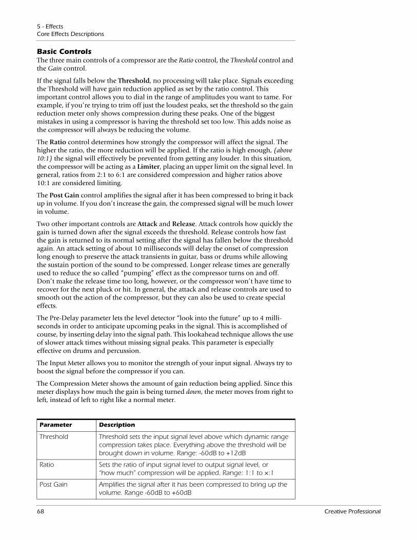
5 - EffectsCore Effects Descriptions
Basic ControlsThe three main controls of a compressor are the Ratio control, the Threshold control and the Gain control.
If the signal falls below the Threshold, no processing will take place. Signals exceeding the Threshold will have gain reduction applied as set by the ratio control. This important control allows you to dial in the range of amplitudes you want to tame. For example, if you’re trying to trim off just the loudest peaks, set the threshold so the gain reduction meter only shows compression during these peaks. One of the biggest mistakes in using a compressor is having the threshold set too low. This adds noise as the compressor will always be reducing the volume.
The Ratio control determines how strongly the compressor will affect the signal. The higher the ratio, the more reduction will be applied. If the ratio is high enough, (above 10:1) the signal will effectively be prevented from getting any louder. In this situation, the compressor will be acting as a Limiter, placing an upper limit on the signal level. In general, ratios from 2:1 to 6:1 are considered compression and higher ratios above 10:1 are considered limiting.
The Post Gain control amplifies the signal after it has been compressed to bring it back up in volume. If you don’t increase the gain, the compressed signal will be much lower in volume.
Two other important controls are Attack and Release. Attack controls how quickly the gain is turned down after the signal exceeds the threshold. Release controls how fast the gain is returned to its normal setting after the signal has fallen below the threshold again. An attack setting of about 10 milliseconds will delay the onset of compression long enough to preserve the attack transients in guitar, bass or drums while allowing the sustain portion of the sound to be compressed. Longer release times are generally used to reduce the so called “pumping” effect as the compressor turns on and off. Don’t make the release time too long, however, or the compressor won’t have time to recover for the next pluck or hit. In general, the attack and release controls are used to smooth out the action of the compressor, but they can also be used to create special effects.
The Pre-Delay parameter lets the level detector “look into the future” up to 4 milli-seconds in order to anticipate upcoming peaks in the signal. This is accomplished of course, by inserting delay into the signal path. This lookahead technique allows the use of slower attack times without missing signal peaks. This parameter is especially effective on drums and percussion.
The Input Meter allows you to monitor the strength of your input signal. Always try to boost the signal before the compressor if you can.
The Compression Meter shows the amount of gain reduction being applied. Since this meter displays how much the gain is being turned down, the meter moves from right to left, instead of left to right like a normal meter.
Parameter Description
Threshold Threshold sets the input signal level above which dynamic range compression takes place. Everything above the threshold will be brought down in volume. Range: -60dB to +12dB
Ratio Sets the ratio of input signal level to output signal level, or “how much” compression will be applied. Range: 1:1 to ×:1
Post Gain Amplifies the signal after it has been compressed to bring up the volume. Range -60dB to +60dB
68 Creative Professional

5 - EffectsCore Effects Descriptions
DistortionMost audio processors aim to provide low distortion, but not this one! The sole purpose of this effect is to add distortion, and lots of it. This effect provides “fuzz box” style, clipping distortion which is particularly effective on guitar, bass, organs, electric pianos or whatever.
The input signal first passes through a lowpass filter. The Lowpass Filter Cutoff Frequency allows you to control the number of new harmonics that will be generated by the distortion element. The distortion element has an Edge control which controls “how much” distortion will be added. A bandpass filter follows the distortion generator. The EQ Center control lets you select a particular band of frequencies to be output. The EQ Bandwidth controls the width of the center frequency band. Finally, a gain control allows you to make up for any gain loss through the effect.
Use the Wet/Dry mix control in conjunction with the Edge control to reduce the amount of distortion, or go wild and turn everything to 11!
In
Edge
LowpassFilter
BandpassFilter
EQ CenterLP FilterCutoff
GainEQ BW
OutDistortion
Signal path = Stereo
Parameter Description
Pre EQ LP Cutoff Controls the amount of high frequency audio admitted to the distortion. Range: 80Hz to 24kHz
Edge Sets the amount of distortion and new harmonics generated. Range: 0-100
Gain Sets the output volume of the effect. Range: -60dB to 0dB
Post EQ Center Freq. Sets the frequency of the output bandpass filter.Range: 80Hz to 24kHz
Post EQ Bandwidth Sets the width of the output bandpass filter. Range: 80Hz to 24kHz
Attack Time Controls how quickly the gain is turned down after the signal exceeds the threshold. Range .1ms to 500ms
Release Time Controls how fast the gain is returned to its normal setting after the signal has fallen below the threshold. Range: 50ms to 3000ms
Pre-Delay Allows the use of slower attack times without missing signal peaks.Range: 0ms to 3 ms
Input Meter Allows you to monitor the strength of the input signal.
Gain Reduction Meter Shows the amount of gain reduction being applied.
Parameter Description
E-MU PCI Digital Audio Systems 69
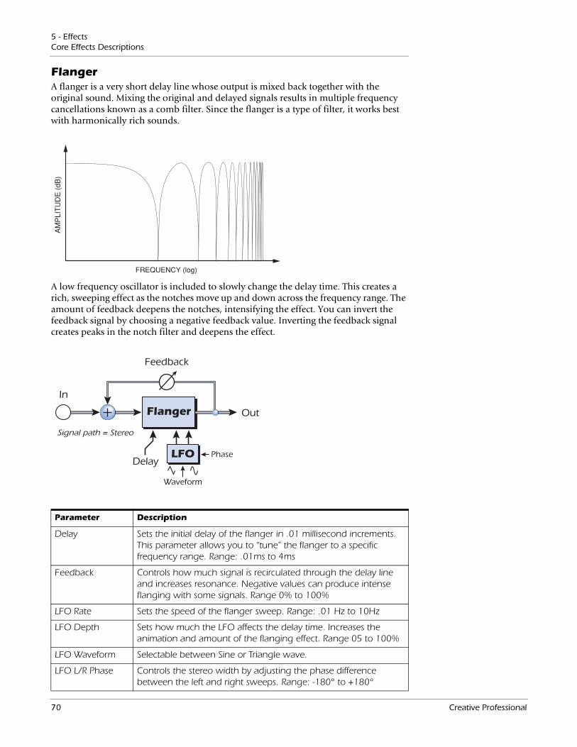
5 - EffectsCore Effects Descriptions
FlangerA flanger is a very short delay line whose output is mixed back together with the original sound. Mixing the original and delayed signals results in multiple frequency cancellations known as a comb filter. Since the flanger is a type of filter, it works best with harmonically rich sounds.
A low frequency oscillator is included to slowly change the delay time. This creates a rich, sweeping effect as the notches move up and down across the frequency range. The amount of feedback deepens the notches, intensifying the effect. You can invert the feedback signal by choosing a negative feedback value. Inverting the feedback signal creates peaks in the notch filter and deepens the effect.
Flanger
LFO
In
Out
Feedback
Delay
Waveform
Phase
Signal path = Stereo
Parameter Description
Delay Sets the initial delay of the flanger in .01 millisecond increments. This parameter allows you to “tune” the flanger to a specific frequency range. Range: .01ms to 4ms
Feedback Controls how much signal is recirculated through the delay line and increases resonance. Negative values can produce intense flanging with some signals. Range 0% to 100%
LFO Rate Sets the speed of the flanger sweep. Range: .01 Hz to 10Hz
LFO Depth Sets how much the LFO affects the delay time. Increases the animation and amount of the flanging effect. Range 05 to 100%
LFO Waveform Selectable between Sine or Triangle wave.
LFO L/R Phase Controls the stereo width by adjusting the phase difference between the left and right sweeps. Range: -180° to +180°
70 Creative Professional
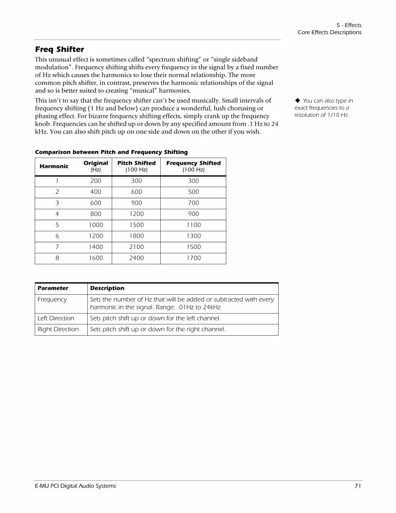
5 - EffectsCore Effects Descriptions
Freq ShifterThis unusual effect is sometimes called “spectrum shifting” or “single sideband modulation”. Frequency shifting shifts every frequency in the signal by a fixed number of Hz which causes the harmonics to lose their normal relationship. The more common pitch shifter, in contrast, preserves the harmonic relationships of the signal and so is better suited to creating “musical” harmonies.
You can also type in exact frequencies to a resolution of 1/10 Hz.
This isn’t to say that the frequency shifter can’t be used musically. Small intervals of frequency shifting (1 Hz and below) can produce a wonderful, lush chorusing or phasing effect. For bizarre frequency shifting effects, simply crank up the frequency knob. Frequencies can be shifted up or down by any specified amount from .1 Hz to 24 kHz. You can also shift pitch up on one side and down on the other if you wish.
Harmonic Original (Hz)
Pitch Shifted(100 Hz)
Frequency Shifted(100 Hz)
1 200 300 300
2 400 600 500
3 600 900 700
4 800 1200 900
5 1000 1500 1100
6 1200 1800 1300
7 1400 2100 1500
8 1600 2400 1700
Comparison between Pitch and Frequency Shifting
Parameter Description
Frequency Sets the number of Hz that will be added or subtracted with every harmonic in the signal. Range: .01Hz to 24kHz
Left Direction Sets pitch shift up or down for the left channel.
Right Direction Sets pitch shift up or down for the right channel.
E-MU PCI Digital Audio Systems 71
5 - EffectsCore Effects Descriptions
Leveling AmpThe first compressors developed in the 1950’s were based on a slow-acting optical gain cells which were able to control the signal level in a very subtle and musical way. This effect is a digital recreation of the leveling amps of yesteryear.
The leveling amp uses a large amount of “lookahead delay” to apply gentle gain reduction. Because of this delay, the leveling amp is not suitable for applications which require realtime monitoring of the signal. This smooth and gentle compressor is designed to be used in situations where delay does not pose a problem, such as mastering a mix or compressing prerecorded stereo material.
Post Gain Amplifies the signal after it has been compressed to bring up the volume. Range 0dB to 36dB
Post Gain is the only control on the leveling amp. This control is used to make up the volume lost by the compression. The Compression Ratio is fixed at about 2.5:1. If a large peak is detected, the effect will automatically increase the compression ratio to keep the audio output controlled.
The gain reduction meter shows you how much gain reduction is being applied. Since the gain reduction meter displays how much the gain is being turned down, the meter moves from right to left, instead of left to right like most meters.
72 Creative Professional

5 - EffectsCore Effects Descriptions
Lite ReverbReverberation is a simulation of a natural space such as a room or hall. The Lite Reverb algorithm is designed to simulate various rooms and reverberation plates while using fewer DSP resources than the Stereo Reverb. Up to five Lite Reverbs can be used at once.
TimeEarly Reflections
Late Reverb
Parameter Description
Decay Time Sets the reverb decay time. Range: 0% to 100%
HF Decay Factor Sets the rate at which high frequencies die away. The high frequencies last longer as the percentage is increased. Range: 0% to 100%
LF Decay Factor Sets the rate at which low frequencies die away. The low frequencies last longer as the percentage is increased.Range: 0% to 100%
Early Reflections Sets the volume of the initial wall reflections.Range: 0% to 100%
Reverberance Sets the amount of scattering of the early reflections and the reverberation cloud. Range: 0% to 100%
Decay time defines the time it takes for the reflected sound from the room to decay or die away. The diagram below shows a generalized reverberation envelope.
After a short pre-delay period, the echoes from the closest walls or ceiling are heard. These first echoes, or Early Reflections, vary greatly depending on the type of room. Some time after the early reflection cluster ends, the actual Reverberation (a dense cloud of complex wall reflections) begins and decays according to the time set by the Decay Time parameter. The Reverberance parameter controls the density and smearing of both the early reflections and the reverberation cloud.
High frequency energy tends to fade away first as a sound is dissipated in a room. The High Frequency Decay Factor adjusts the time it takes for the high frequency energy to die away and thus changes the characteristics of the room. Rooms with smooth, hard surfaces are more reflective and have less high frequency damping. Rooms filled with sound absorbing materials, such as curtains or people, have more high frequency damping.
The Low Frequency Decay Factor parameter adjusts the time it takes for the low frequencies to die away. This control adjusts the “boominess” of the room.
E-MU PCI Digital Audio Systems 73
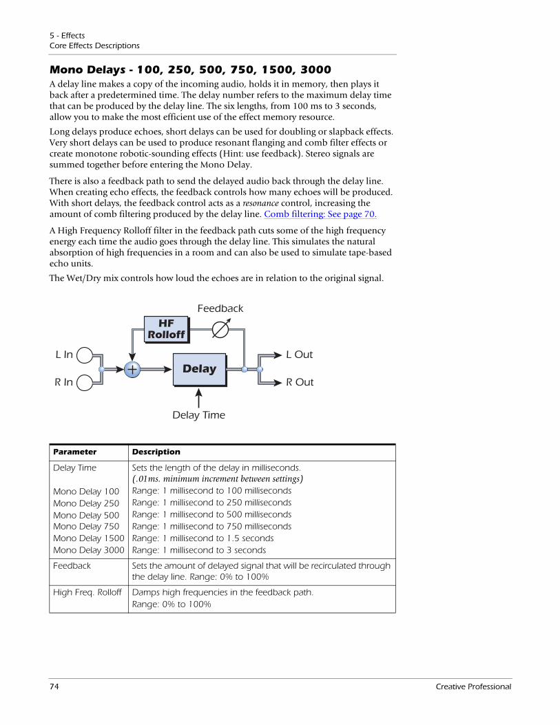
5 - EffectsCore Effects Descriptions
Mono Delays - 100, 250, 500, 750, 1500, 3000A delay line makes a copy of the incoming audio, holds it in memory, then plays it back after a predetermined time. The delay number refers to the maximum delay time that can be produced by the delay line. The six lengths, from 100 ms to 3 seconds, allow you to make the most efficient use of the effect memory resource.
Long delays produce echoes, short delays can be used for doubling or slapback effects. Very short delays can be used to produce resonant flanging and comb filter effects or create monotone robotic-sounding effects (Hint: use feedback). Stereo signals are summed together before entering the Mono Delay.
There is also a feedback path to send the delayed audio back through the delay line. When creating echo effects, the feedback controls how many echoes will be produced. With short delays, the feedback control acts as a resonance control, increasing the amount of comb filtering produced by the delay line. Comb filtering: See page 70.
A High Frequency Rolloff filter in the feedback path cuts some of the high frequency energy each time the audio goes through the delay line. This simulates the natural absorption of high frequencies in a room and can also be used to simulate tape-based echo units.
The Wet/Dry mix controls how loud the echoes are in relation to the original signal.
DelayL In
Feedback
Delay Time
R In
L Out
R Out
HFRolloff
Parameter Description
Delay Time
Mono Delay 100Mono Delay 250Mono Delay 500 Mono Delay 750Mono Delay 1500Mono Delay 3000
Sets the length of the delay in milliseconds. (.01ms. minimum increment between settings)Range: 1 millisecond to 100 millisecondsRange: 1 millisecond to 250 millisecondsRange: 1 millisecond to 500 millisecondsRange: 1 millisecond to 750 millisecondsRange: 1 millisecond to 1.5 secondsRange: 1 millisecond to 3 seconds
Feedback Sets the amount of delayed signal that will be recirculated through the delay line. Range: 0% to 100%
High Freq. Rolloff Damps high frequencies in the feedback path.Range: 0% to 100%
74 Creative Professional
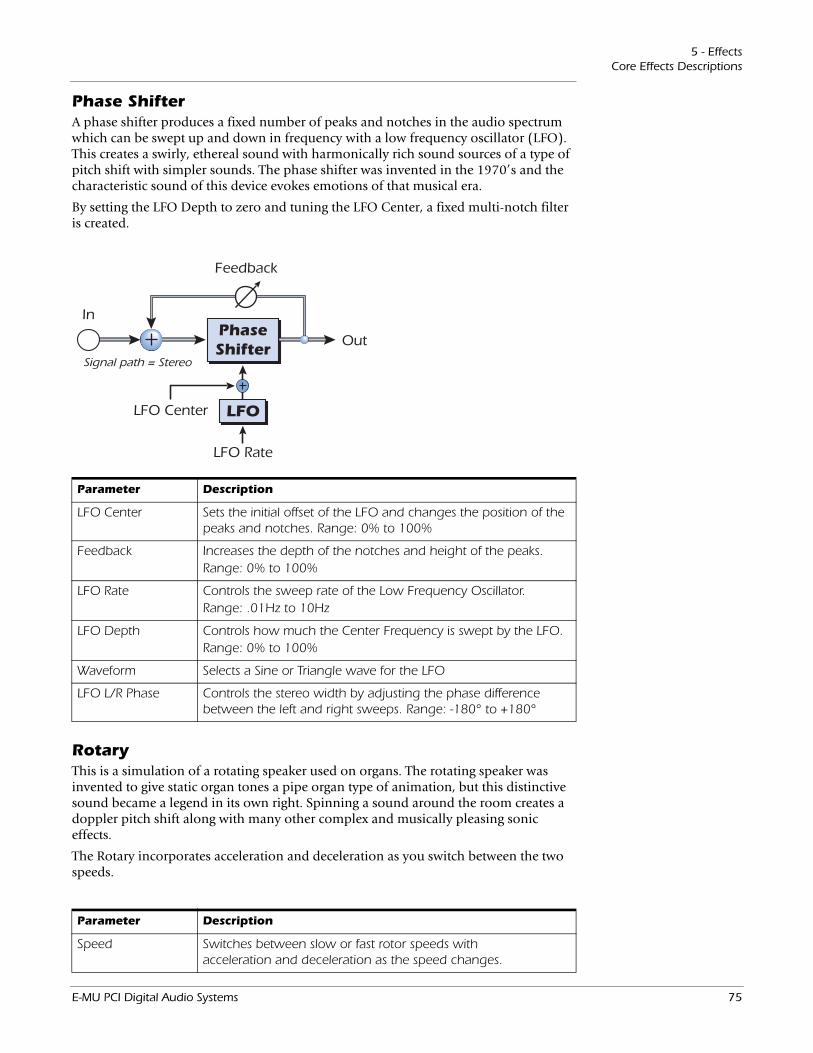
5 - EffectsCore Effects Descriptions
Phase ShifterA phase shifter produces a fixed number of peaks and notches in the audio spectrum which can be swept up and down in frequency with a low frequency oscillator (LFO). This creates a swirly, ethereal sound with harmonically rich sound sources of a type of pitch shift with simpler sounds. The phase shifter was invented in the 1970’s and the characteristic sound of this device evokes emotions of that musical era.
By setting the LFO Depth to zero and tuning the LFO Center, a fixed multi-notch filter is created.
PhaseShifter
LFO
In
Out
Feedback
LFO Center
LFO Rate
Signal path = Stereo
Parameter Description
LFO Center Sets the initial offset of the LFO and changes the position of the peaks and notches. Range: 0% to 100%
Feedback Increases the depth of the notches and height of the peaks.Range: 0% to 100%
LFO Rate Controls the sweep rate of the Low Frequency Oscillator.Range: .01Hz to 10Hz
LFO Depth Controls how much the Center Frequency is swept by the LFO.Range: 0% to 100%
Waveform Selects a Sine or Triangle wave for the LFO
LFO L/R Phase Controls the stereo width by adjusting the phase difference between the left and right sweeps. Range: -180° to +180°
RotaryThis is a simulation of a rotating speaker used on organs. The rotating speaker was invented to give static organ tones a pipe organ type of animation, but this distinctive sound became a legend in its own right. Spinning a sound around the room creates a doppler pitch shift along with many other complex and musically pleasing sonic effects.
The Rotary incorporates acceleration and deceleration as you switch between the two speeds.
Parameter Description
Speed Switches between slow or fast rotor speeds with acceleration and deceleration as the speed changes.
E-MU PCI Digital Audio Systems 75
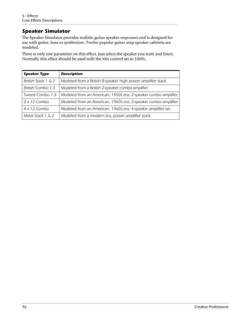
5 - EffectsCore Effects Descriptions
Speaker SimulatorThe Speaker Simulator provides realistic guitar speaker responses and is designed for use with guitar, bass or synthesizer. Twelve popular guitar amp speaker cabinets are modeled.
There is only one parameter on this effect. Just select the speaker you want and listen. Normally this effect should be used with the Mix control set to 100%.
Speaker Type Description
British Stack 1 & 2 Modeled from a British 8-speaker high power amplifier stack.
British Combo 1-3 Modeled from a British 2-speaker combo amplifier.
Tweed Combo 1-3 Modeled from an American, 1950’s era, 2-speaker combo amplifier.
2 x 12 Combo Modeled from an American, 1960’s era, 2-speaker combo amplifier.
4 x 12 Combo Modeled from an American, 1960’s era, 4-speaker amplifier set.
Metal Stack 1 & 2 Modeled from a modern era, power amplifier stack.
76 Creative Professional
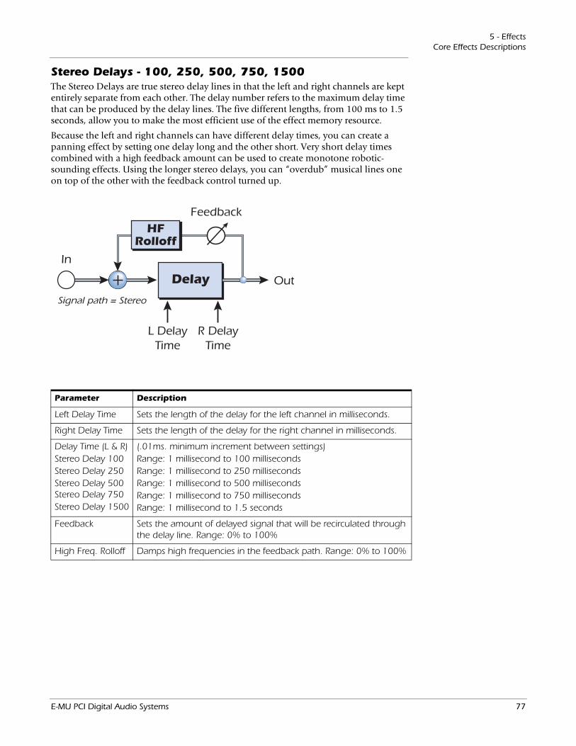
5 - EffectsCore Effects Descriptions
Stereo Delays - 100, 250, 500, 750, 1500The Stereo Delays are true stereo delay lines in that the left and right channels are kept entirely separate from each other. The delay number refers to the maximum delay time that can be produced by the delay lines. The five different lengths, from 100 ms to 1.5 seconds, allow you to make the most efficient use of the effect memory resource.
Because the left and right channels can have different delay times, you can create a panning effect by setting one delay long and the other short. Very short delay times combined with a high feedback amount can be used to create monotone robotic-sounding effects. Using the longer stereo delays, you can “overdub” musical lines one on top of the other with the feedback control turned up.
Delay
In
Out
Feedback
R DelayTime
L DelayTime
HFRolloff
Signal path = Stereo
Parameter Description
Left Delay Time Sets the length of the delay for the left channel in milliseconds.
Right Delay Time Sets the length of the delay for the right channel in milliseconds.
Delay Time (L & R)Stereo Delay 100Stereo Delay 250Stereo Delay 500 Stereo Delay 750Stereo Delay 1500
(.01ms. minimum increment between settings)Range: 1 millisecond to 100 millisecondsRange: 1 millisecond to 250 millisecondsRange: 1 millisecond to 500 millisecondsRange: 1 millisecond to 750 millisecondsRange: 1 millisecond to 1.5 seconds
Feedback Sets the amount of delayed signal that will be recirculated through the delay line. Range: 0% to 100%
High Freq. Rolloff Damps high frequencies in the feedback path. Range: 0% to 100%
E-MU PCI Digital Audio Systems 77
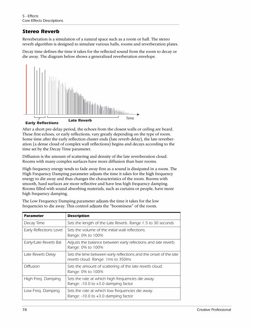
5 - EffectsCore Effects Descriptions
Stereo ReverbReverberation is a simulation of a natural space such as a room or hall. The stereo reverb algorithm is designed to simulate various halls, rooms and reverberation plates.
TimeEarly Reflections
Late Reverb
Parameter Description
Decay Time Sets the length of the Late Reverb. Range 1.5 to 30 seconds
Early Reflections Level Sets the volume of the initial wall reflections.Range: 0% to 100%
Early/Late Reverb Bal Adjusts the balance between early refections and late reverb. Range: 0% to 100%
Late Reverb Delay Sets the time between early reflections and the onset of the late reverb cloud. Range: 1ms to 350ms
Diffusion Sets the amount of scattering of the late reverb cloud.Range: 0% to 100%
High Freq. Damping Sets the rate at which high frequencies die away. Range: -10.0 to +3.0 damping factor
Low Freq. Damping Sets the rate at which low frequencies die away.Range: -10.0 to +3.0 damping factor
Decay time defines the time it takes for the reflected sound from the room to decay or die away. The diagram below shows a generalized reverberation envelope.
After a short pre-delay period, the echoes from the closest walls or ceiling are heard. These first echoes, or early reflections, vary greatly depending on the type of room. Some time after the early reflection cluster ends (late reverb delay), the late reverber-ation (a dense cloud of complex wall reflections) begins and decays according to the time set by the Decay Time parameter.
Diffusion is the amount of scattering and density of the late reverberation cloud. Rooms with many complex surfaces have more diffusion than bare rooms.
High frequency energy tends to fade away first as a sound is dissipated in a room. The High Frequency Damping parameter adjusts the time it takes for the high frequency energy to die away and thus changes the characteristics of the room. Rooms with smooth, hard surfaces are more reflective and have less high frequency damping. Rooms filled with sound absorbing materials, such as curtains or people, have more high frequency damping.
The Low Frequency Damping parameter adjusts the time it takes for the low frequencies to die away. This control adjusts the “boominess” of the room.
78 Creative Professional
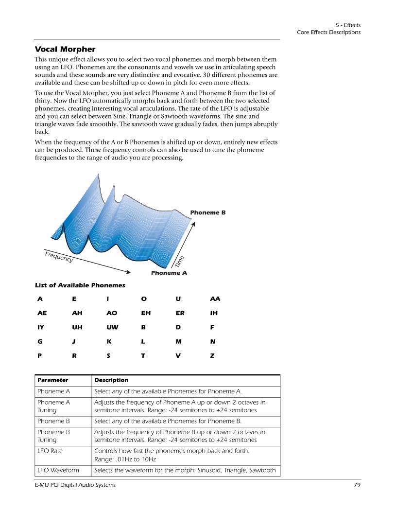
5 - EffectsCore Effects Descriptions
Vocal MorpherThis unique effect allows you to select two vocal phonemes and morph between them using an LFO. Phonemes are the consonants and vowels we use in articulating speech sounds and these sounds are very distinctive and evocative. 30 different phonemes are available and these can be shifted up or down in pitch for even more effects.
To use the Vocal Morpher, you just select Phoneme A and Phoneme B from the list of thirty. Now the LFO automatically morphs back and forth between the two selected phonemes, creating interesting vocal articulations. The rate of the LFO is adjustable and you can select between Sine, Triangle or Sawtooth waveforms. The sine and triangle waves fade smoothly. The sawtooth wave gradually fades, then jumps abruptly back.
When the frequency of the A or B Phonemes is shifted up or down, entirely new effects can be produced. These frequency controls can also be used to tune the phoneme frequencies to the range of audio you are processing.
Frequency
Tim
e
Phoneme A
Phoneme B
A E I O U AA
AE AH AO EH ER IH
IY UH UW B D F
G J K L M N
P R S T V Z
List of Available Phonemes
Parameter Description
Phoneme A Select any of the available Phonemes for Phoneme A.
Phoneme A Tuning
Adjusts the frequency of Phoneme A up or down 2 octaves in semitone intervals. Range: -24 semitones to +24 semitones
Phoneme B Select any of the available Phonemes for Phoneme B.
Phoneme B Tuning
Adjusts the frequency of Phoneme B up or down 2 octaves in semitone intervals. Range: -24 semitones to +24 semitones
LFO Rate Controls how fast the phonemes morph back and forth.Range: .01Hz to 10Hz
LFO Waveform Selects the waveform for the morph: Sinusoid, Triangle, Sawtooth
E-MU PCI Digital Audio Systems 79
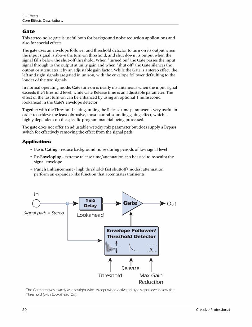
5 - EffectsCore Effects Descriptions
GateThis stereo noise gate is useful both for background noise reduction applications and also for special effects.
The gate uses an envelope follower and threshold detector to turn on its output when the input signal is above the turn-on threshold, and shut down its output when the signal falls below the shut-off threshold. When ”turned on” the Gate passes the input signal through to the output at unity gain and when “shut off” the Gate silences the output or attenuates it by an adjustable gain factor. While the Gate is a stereo effect, the left and right signals are gated in unison, with the envelope follower defaulting to the louder of the two signals.
In normal operating mode, Gate turn-on is nearly instantaneous when the input signal exceeds the Threshold level, while Gate Release time is an adjustable parameter. The effect of the fast turn-on can be enhanced by using an optional 1 millisecond lookahead in the Gate's envelope detector.
Together with the Threshold setting, tuning the Release time parameter is very useful in order to achieve the least-obtrusive, most natural-sounding gating effect, which is highly dependent on the specific program material being processed.
The gate does not offer an adjustable wet/dry mix parameter but does supply a Bypass switch for effectively removing the effect from the signal path.
Applications
• Basic Gating - reduce background noise during periods of low signal level
• Re-Enveloping - extreme release time/attenuation can be used to re-sculpt the signal envelope
• Punch Enhancement - high threshold+fast shuttoff+modest attenuation perform an expander-like function that accentuates transients
Out
Threshold Max GainReduction
Lookahead
Release
Gate1mSDelay
Signal path = Stereo
Envelope Follower/Threshold Detector
In
The Gate behaves exactly as a straight wire, except when activated by a signal level below the Threshold (with Lookahead Off).
80 Creative Professional
5 - EffectsCore Effects Descriptions
Parameters
ThresholdWhen the input signal rises above the level set by the Threshold parameter, the Gate is triggered to turn on and go from its maximum gain reduction level up to 0dB gain. The turn-on threshold is adjustable anywhere between -70dB and 0dB (below the PatchMix nominal operating point of -12dBFS.)
One of the keys to the smooth operation of the Gate is that the input Threshold level that turns on the Gate is always higher than the level that shuts off the gate. This means that the input signal level must descend substantially below the Threshold in order to turn off again.
This difference between turn-on and shut-off levels, or the hysteresis, is 10dB. That means that if the Threshold is -30dB, the signal level must fall to -40dB before the Gate will begin to shut off.
Release TimeThis parameter controls the time, in milliseconds, that is required for the Gate to shut off. More specifically, this is the time that will be required for the Gate control signal to go from unity gain at 0dB down to the Max Gain Reduction level.
The optimum value for the Release time is dependent on the program material as well as the effect you're trying to achieve. Optimum Release time is also highly dependent upon the settings of the Threshold and Max Gain Reduction parameters.
In general, times less than about 10 msec are prone to cause clicks in the output, while times longer than 30 msec may make the gating effect obvious if the background signal being gated out is very noisy.
Max Gain ReductionThis parameter sets the attenuation that will be applied to the signal when the Gate is shut off. The Gate control signal will swing between 0dB and this value as the Gate turns on and shuts off.
To perform a strict “gating” operation, Max Gain Reduction would normally be set to -infinity in order to completely silence the output of the Gate.
However, there are good reasons to set Max Gain Reduction to something less drastic than infinite attenuation. Sometimes the silence between gated signals is “too quiet” - especially when the signal represents a solo vocal or instrument, where the complete lack of any sound between voiced segments sounds unnatural. For these applications, setting Max Gain Reduction somewhere between -20dB and -40dB is more appropriate.
In tandem with a high Threshold, Max Gain Reduction can also be set to very modest values like -5 or -10dB in order to add a subtle “punch” enhancement to transients. This has an effect similar to an expander, where the attack transients which exceed the Threshold stand out by 5 or 10dB above the normal signal (you can make up for that 5 or 10dB attenuation by using a trim pot or boosting the channel strip gain after the Gate.)
LookaheadBy default, the Gate effect uses a fixed 1 millisecond lookahead to avoid clipping off the leading edge of signal transients when the Gate turns on. However, this is actually implemented by adding a 1 millisecond delay to the signal through the gate. For appli-cations where this additional 1 millisecond latency is a problem, the Lookahead can be turned Off.
E-MU PCI Digital Audio Systems 81
5 - EffectsCore Effects Descriptions
Level MeterThis meter represents the input signal level in dB, and is in fact the output of the Gate's envelope follower. Since the envelope follower is driven by the greater of the left or right channel, this monophonic meter represents the greater of the two input signals.
Gain Reduction MeterThis meter shows the value in dB of the gate control signal which is used to boost or attenuate the input signal. Its most-rightward maximum value of 0dB represents a unity gain path through the Gate in its turn-on state. Except for the possibility of the 1 millisecond lookahead latency, the Gate behaves exactly as a straight wire in this turned-on state. Values less than 0dB represent the amount by which the input signal is being attenuated as the Gate shuts off.
The most-leftward gain shutoff value achieved by the Gain meter is set by the Max Gain Reduction parameter (values from -70dB to -infinity are off the meter.) The speed with which the Gain signal decays from 0dB to the shutoff value can be observed to change according to the Release time parameter.
82 Creative Professional
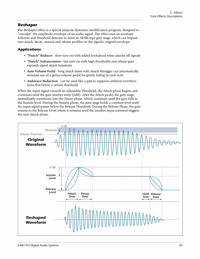
5 - EffectsCore Effects Descriptions
ReshaperThe Reshaper effect is a special purpose dynamics modification program, designed to “resculpt” the amplitude envelope of an audio signal. The effect uses an envelope follower and threshold detector to drive an ADSR-type gain stage, which can impose new attack, decay, sustain and release profiles on the signal's original envelope.
Applications
• “Punch” Reducer - slow turn-on with added lookahead trims attacks off signals
• “Punch” Enhancement - fast turn on with high thresholds and release gain expands signal attack transients
• Auto Volume Pedal - long attack times with Attack Retrigger can automatically simulate use of a guitar volume pedal for gently fading in each note.
• Ambience Reduction - can be used like a gate to suppress ambient reverbera-tions that below a certain threshold.
Threshold
Release Threshold
0 dB
ReleaseLevel
SustainLevel
AttackTime
DecayTime
HoldTime
ReleaseTime
0 dB
OriginalWaveform
ReshapedWaveform
When the input signal exceeds an adjustable Threshold, the Attack phase begins and continues until the gain reaches unity (0dB). After the Attack peaks, the gain stage immediately transitions into the Decay phase, which continues until the gain falls to the Sustain level. During the Sustain phase, the gain stage holds a constant level until the input signal passes below the Release Threshold. During the Release Phase, the gain returns to the Release Level where it remains until the another input transient triggers the next Attack phase.
E-MU PCI Digital Audio Systems 83
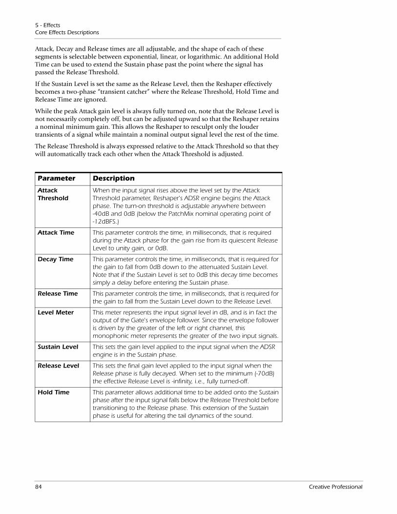
5 - EffectsCore Effects Descriptions
Attack, Decay and Release times are all adjustable, and the shape of each of these segments is selectable between exponential, linear, or logarithmic. An additional Hold Time can be used to extend the Sustain phase past the point where the signal has passed the Release Threshold.
If the Sustain Level is set the same as the Release Level, then the Reshaper effectively becomes a two-phase “transient catcher” where the Release Threshold, Hold Time and Release Time are ignored.
While the peak Attack gain level is always fully turned on, note that the Release Level is not necessarily completely off, but can be adjusted upward so that the Reshaper retains a nominal minimum gain. This allows the Reshaper to resculpt only the louder transients of a signal while maintain a nominal output signal level the rest of the time.
The Release Threshold is always expressed relative to the Attack Threshold so that they will automatically track each other when the Attack Threshold is adjusted.
Parameter Description
Attack Threshold
When the input signal rises above the level set by the Attack Threshold parameter, Reshaper's ADSR engine begins the Attack phase. The turn-on threshold is adjustable anywhere between -40dB and 0dB (below the PatchMix nominal operating point of -12dBFS.)
Attack Time This parameter controls the time, in milliseconds, that is required during the Attack phase for the gain rise from its quiescent Release Level to unity gain, or 0dB.
Decay Time This parameter controls the time, in milliseconds, that is required for the gain to fall from 0dB down to the attenuated Sustain Level. Note that if the Sustain Level is set to 0dB this decay time becomes simply a delay before entering the Sustain phase.
Release Time This parameter controls the time, in milliseconds, that is required for the gain to fall from the Sustain Level down to the Release Level.
Level Meter This meter represents the input signal level in dB, and is in fact the output of the Gate's envelope follower. Since the envelope follower is driven by the greater of the left or right channel, this monophonic meter represents the greater of the two input signals.
Sustain Level This sets the gain level applied to the input signal when the ADSR engine is in the Sustain phase.
Release Level This sets the final gain level applied to the input signal when the Release phase is fully decayed. When set to the minimum (-70dB) the effective Release Level is -infinity, i.e., fully turned-off.
Hold Time This parameter allows additional time to be added onto the Sustain phase after the input signal falls below the Release Threshold before transitioning to the Release phase. This extension of the Sustain phase is useful for altering the tail dynamics of the sound.
84 Creative Professional
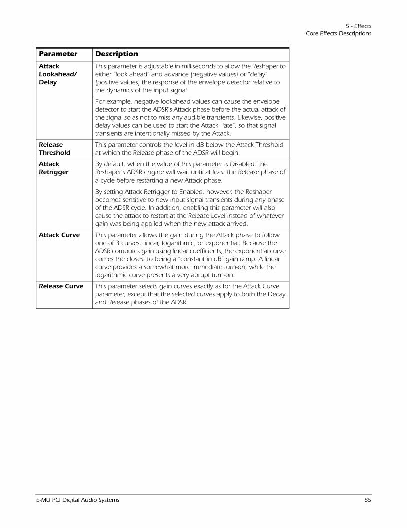
5 - EffectsCore Effects Descriptions
Attack Lookahead/Delay
This parameter is adjustable in milliseconds to allow the Reshaper to either “look ahead” and advance (negative values) or “delay” (positive values) the response of the envelope detector relative to the dynamics of the input signal.
For example, negative lookahead values can cause the envelope detector to start the ADSR's Attack phase before the actual attack of the signal so as not to miss any audible transients. Likewise, positive delay values can be used to start the Attack “late”, so that signal transients are intentionally missed by the Attack.
Release Threshold
This parameter controls the level in dB below the Attack Threshold at which the Release phase of the ADSR will begin.
Attack Retrigger
By default, when the value of this parameter is Disabled, the Reshaper's ADSR engine will wait until at least the Release phase of a cycle before restarting a new Attack phase.
By setting Attack Retrigger to Enabled, however, the Reshaper becomes sensitive to new input signal transients during any phase of the ADSR cycle. In addition, enabling this parameter will also cause the attack to restart at the Release Level instead of whatever gain was being applied when the new attack arrived.
Attack Curve This parameter allows the gain during the Attack phase to follow one of 3 curves: linear, logarithmic, or exponential. Because the ADSR computes gain using linear coefficients, the exponential curve comes the closest to being a “constant in dB” gain ramp. A linear curve provides a somewhat more immediate turn-on, while the logarithmic curve presents a very abrupt turn-on.
Release Curve This parameter selects gain curves exactly as for the Attack Curve parameter, except that the selected curves apply to both the Decay and Release phases of the ADSR.
Parameter Description
E-MU PCI Digital Audio Systems 85
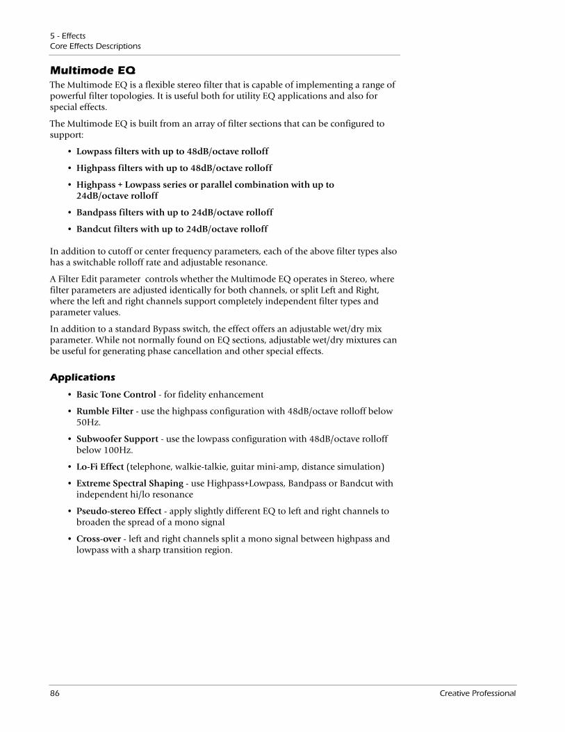
5 - EffectsCore Effects Descriptions
Multimode EQThe Multimode EQ is a flexible stereo filter that is capable of implementing a range of powerful filter topologies. It is useful both for utility EQ applications and also for special effects.
The Multimode EQ is built from an array of filter sections that can be configured to support:
• Lowpass filters with up to 48dB/octave rolloff
• Highpass filters with up to 48dB/octave rolloff
• Highpass + Lowpass series or parallel combination with up to 24dB/octave rolloff
• Bandpass filters with up to 24dB/octave rolloff
• Bandcut filters with up to 24dB/octave rolloff
In addition to cutoff or center frequency parameters, each of the above filter types also has a switchable rolloff rate and adjustable resonance.
A Filter Edit parameter controls whether the Multimode EQ operates in Stereo, where filter parameters are adjusted identically for both channels, or split Left and Right, where the left and right channels support completely independent filter types and parameter values.
In addition to a standard Bypass switch, the effect offers an adjustable wet/dry mix parameter. While not normally found on EQ sections, adjustable wet/dry mixtures can be useful for generating phase cancellation and other special effects.
Applications
• Basic Tone Control - for fidelity enhancement
• Rumble Filter - use the highpass configuration with 48dB/octave rolloff below 50Hz.
• Subwoofer Support - use the lowpass configuration with 48dB/octave rolloff below 100Hz.
• Lo-Fi Effect (telephone, walkie-talkie, guitar mini-amp, distance simulation)
• Extreme Spectral Shaping - use Highpass+Lowpass, Bandpass or Bandcut with independent hi/lo resonance
• Pseudo-stereo Effect - apply slightly different EQ to left and right channels to broaden the spread of a mono signal
• Cross-over - left and right channels split a mono signal between highpass and lowpass with a sharp transition region.
86 Creative Professional
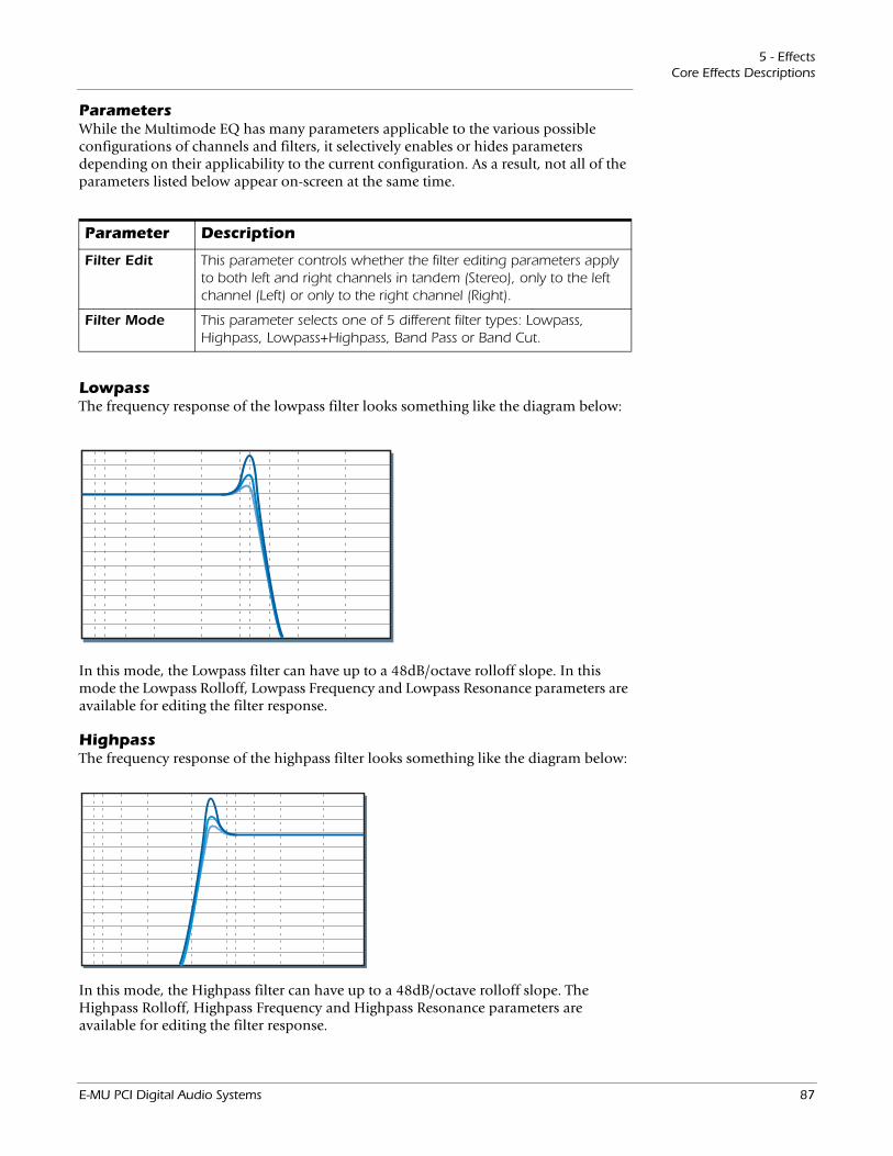
5 - EffectsCore Effects Descriptions
ParametersWhile the Multimode EQ has many parameters applicable to the various possible configurations of channels and filters, it selectively enables or hides parameters depending on their applicability to the current configuration. As a result, not all of the parameters listed below appear on-screen at the same time.
Parameter Description
Filter Edit This parameter controls whether the filter editing parameters apply to both left and right channels in tandem (Stereo), only to the left channel (Left) or only to the right channel (Right).
Filter Mode This parameter selects one of 5 different filter types: Lowpass, Highpass, Lowpass+Highpass, Band Pass or Band Cut.
LowpassThe frequency response of the lowpass filter looks something like the diagram below:
In this mode, the Lowpass filter can have up to a 48dB/octave rolloff slope. In this mode the Lowpass Rolloff, Lowpass Frequency and Lowpass Resonance parameters are available for editing the filter response.
HighpassThe frequency response of the highpass filter looks something like the diagram below:
In this mode, the Highpass filter can have up to a 48dB/octave rolloff slope. The Highpass Rolloff, Highpass Frequency and Highpass Resonance parameters are available for editing the filter response.
E-MU PCI Digital Audio Systems 87
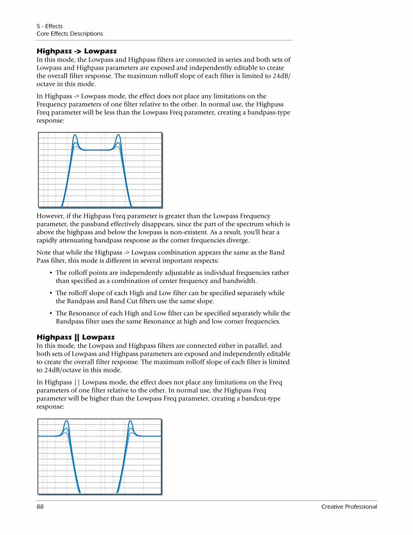
5 - EffectsCore Effects Descriptions
Highpass -> LowpassIn this mode, the Lowpass and Highpass filters are connected in series and both sets of Lowpass and Highpass parameters are exposed and independently editable to create the overall filter response. The maximum rolloff slope of each filter is limited to 24dB/octave in this mode.
In Highpass -> Lowpass mode, the effect does not place any limitations on the Frequency parameters of one filter relative to the other. In normal use, the Highpass Freq parameter will be less than the Lowpass Freq parameter, creating a bandpass-type response:
However, if the Highpass Freq parameter is greater than the Lowpass Frequency parameter, the passband effectively disappears, since the part of the spectrum which is above the highpass and below the lowpass is non-existent. As a result, you'll hear a rapidly attenuating bandpass response as the corner frequencies diverge.
Note that while the Highpass -> Lowpass combination appears the same as the Band Pass filter, this mode is different in several important respects:
• The rolloff points are independently adjustable as individual frequencies rather than specified as a combination of center frequency and bandwidth.
• The rolloff slope of each High and Low filter can be specified separately while the Bandpass and Band Cut filters use the same slope.
• The Resonance of each High and Low filter can be specified separately while the Bandpass filter uses the same Resonance at high and low corner frequencies.
Highpass || LowpassIn this mode, the Lowpass and Highpass filters are connected either in parallel, and both sets of Lowpass and Highpass parameters are exposed and independently editable to create the overall filter response. The maximum rolloff slope of each filter is limited to 24dB/octave in this mode.
In Highpass || Lowpass mode, the effect does not place any limitations on the Freq parameters of one filter relative to the other. In normal use, the Highpass Freq parameter will be higher than the Lowpass Freq parameter, creating a bandcut-type response:
88 Creative Professional
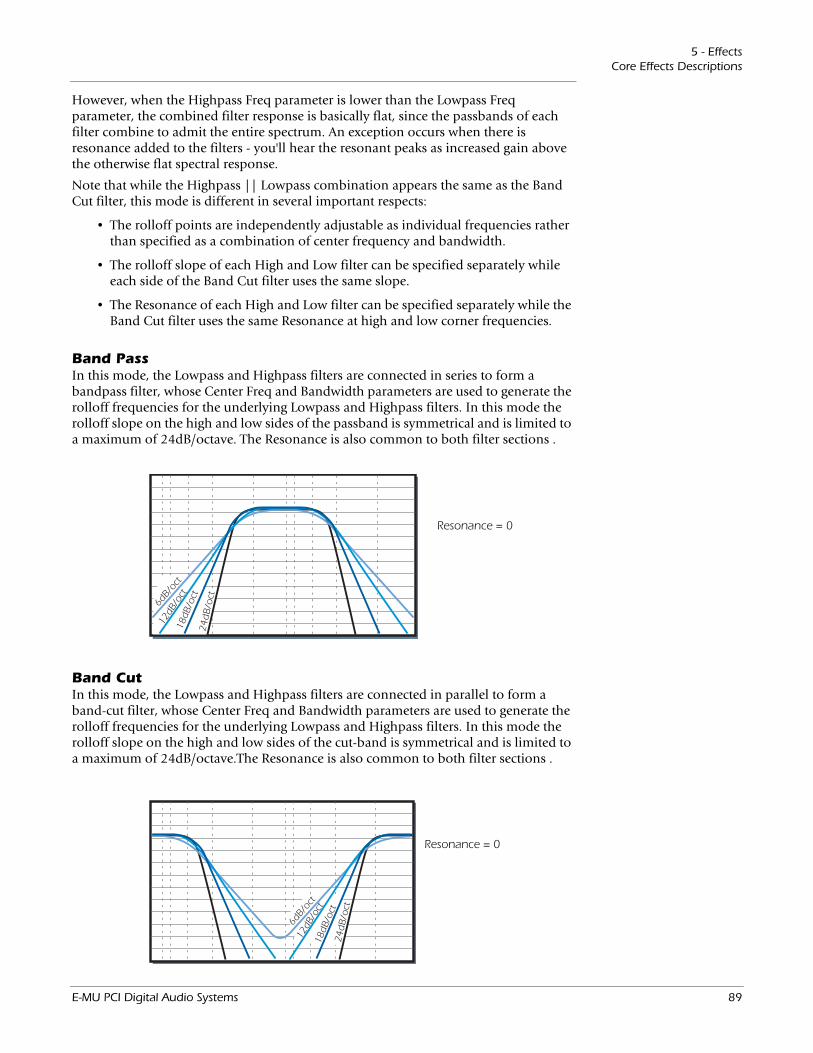
5 - EffectsCore Effects Descriptions
However, when the Highpass Freq parameter is lower than the Lowpass Freq parameter, the combined filter response is basically flat, since the passbands of each filter combine to admit the entire spectrum. An exception occurs when there is resonance added to the filters - you'll hear the resonant peaks as increased gain above the otherwise flat spectral response.
Note that while the Highpass || Lowpass combination appears the same as the Band Cut filter, this mode is different in several important respects:
• The rolloff points are independently adjustable as individual frequencies rather than specified as a combination of center frequency and bandwidth.
• The rolloff slope of each High and Low filter can be specified separately while each side of the Band Cut filter uses the same slope.
• The Resonance of each High and Low filter can be specified separately while the Band Cut filter uses the same Resonance at high and low corner frequencies.
Band PassIn this mode, the Lowpass and Highpass filters are connected in series to form a bandpass filter, whose Center Freq and Bandwidth parameters are used to generate the rolloff frequencies for the underlying Lowpass and Highpass filters. In this mode the rolloff slope on the high and low sides of the passband is symmetrical and is limited to a maximum of 24dB/octave. The Resonance is also common to both filter sections .
18dB
/oct
24d
B/oc
t
6dB/
oct
12dB
/oct
Resonance = 0
Band CutIn this mode, the Lowpass and Highpass filters are connected in parallel to form a band-cut filter, whose Center Freq and Bandwidth parameters are used to generate the rolloff frequencies for the underlying Lowpass and Highpass filters. In this mode the rolloff slope on the high and low sides of the cut-band is symmetrical and is limited to a maximum of 24dB/octave.The Resonance is also common to both filter sections .
18dB
/oct
24d
B/oc
t
6dB/
oct
12dB
/oct
Resonance = 0
E-MU PCI Digital Audio Systems 89
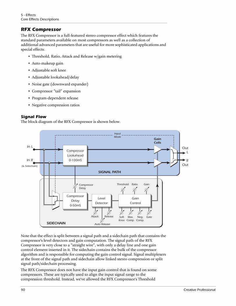
5 - EffectsCore Effects Descriptions
RFX CompressorThe RFX Compressor is a full-featured stereo compressor effect which features the standard parameters available on most compressors as well as a collection of additional advanced parameters that are useful for more sophisticated applications and special effects:
• Threshold, Ratio, Attack and Release w/gain metering
• Auto-makeup gain
• Adjustable soft knee
• Adjustable lookahead/delay
• Noise gate (downward expander)
• Compressor “tail” expansion
• Program-dependent release
• Negative compression ratios
Signal FlowThe block diagram of the RFX Compressor is shown below.
In L
In R
OutL
ROut
Compressor
Lookahead
0-100mS
CompressorDelay
Attack
Auto Release
Release SoftKnee
Max.Comp.
Neg.Comp.
Compressor
Delay
0-50mS
Level
Detector
Gain
Control
Threshold Ratio Gain
Gate
(& Sidechain)
InputMode
GainCells
SIGNAL PATH
SIDECHAIN
Note that the effect is split between a signal path and a sidechain path that contains the compressor's level detectors and gain computation. The signal path of the RFX Compressor is very close to a “straight wire”, with only a delay line and one gain control element inserted in it. The sidechain contains the bulk of the compressor algorithm and is responsible for computing the gain control signal. Signal multiplexers at the front of the signal path and sidechain allow linked stereo compression or split signal path/sidechain processing.
The RFX Compressor does not have the input gain control that is found on some compressors. These are typically used to align the input signal range to the compression threshold. Instead, we've allowed the RFX Compressor's Threshold
90 Creative Professional
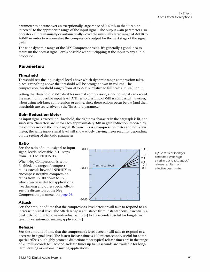
5 - EffectsCore Effects Descriptions
parameter to operate over an exceptionally large range of 0-60dB so that it can be “steered” to the appropriate range of the input signal. The output Gain parameter also operates - either manually or automatically - over the unusually large range of -60dB to +60dB in order to renormalize the compressor's output for the next stage of the signal path.
The wide dynamic range of the RFX Compressor aside, it's generally a good idea to maintain the hottest signal levels possible without clipping at the input to any audio processor.
Parameters
ThresholdThreshold sets the input signal level above which dynamic range compression takes place. Everything above the threshold will be brought down in volume. The compression threshold ranges from -0 to -60dB, relative to full scale (0dBFS) input.
Setting the Threshold to 0dB disables normal compression, since no signal can exceed the maximum possible input level. A Threshold setting of 0dB is still useful, however, when using soft-knee compression or gating, since these actions occur below (and their thresholds are set relative to) the Threshold parameter.
Gain Reduction MeterAs input signals exceed the Threshold, the rightness character in the bargraph is lit, and successive characters are lit for each approximately 3dB in gain reduction imposed by the compressor on the input signal. Because this is a compression meter and not a level meter, the same input signal level will show widely varying meter readings depending on the setting of the Ratio parameter.
0dB 1.1:1
1.5:12:13:110:1 :1-30dB
-80dB
Threshold: -30dB 8
Tip: A ratio of Infinity:1 combined with high threshold and fast attack/release results in an effective peak limiter.
RatioSets the ratio of output signal to input signal levels, selectable in 16 steps from 1:1.1 to 1:INFINITY.
When Neg Compression is set to Enabled, the range of compression ratios extends beyond INFINITY to encompass negative compression ratios from 1:-100 down to 1:-1, which can be useful for applications like ducking and other special effects. See the discussion of the Neg Compression parameter on page 96.
AttackSets the amount of time that the compressor's level detector will take to respond to an increase in signal level. The Attack range is adjustable from Instantaneous (essentially a peak detector that follows individual samples) to 10 seconds (useful for long-term leveling or automatic mixing applications.)
ReleaseSets the amount of time that the compressor's level detector will take to respond to a decrease in signal level. The fastest Release time is 100 microseconds, useful for some special effects but highly prone to distortion; more typical release times are in the range of 70 milliseconds to 1 second. Release times up to 10 seconds are available for long-term leveling or automatic mixing applications.
E-MU PCI Digital Audio Systems 91
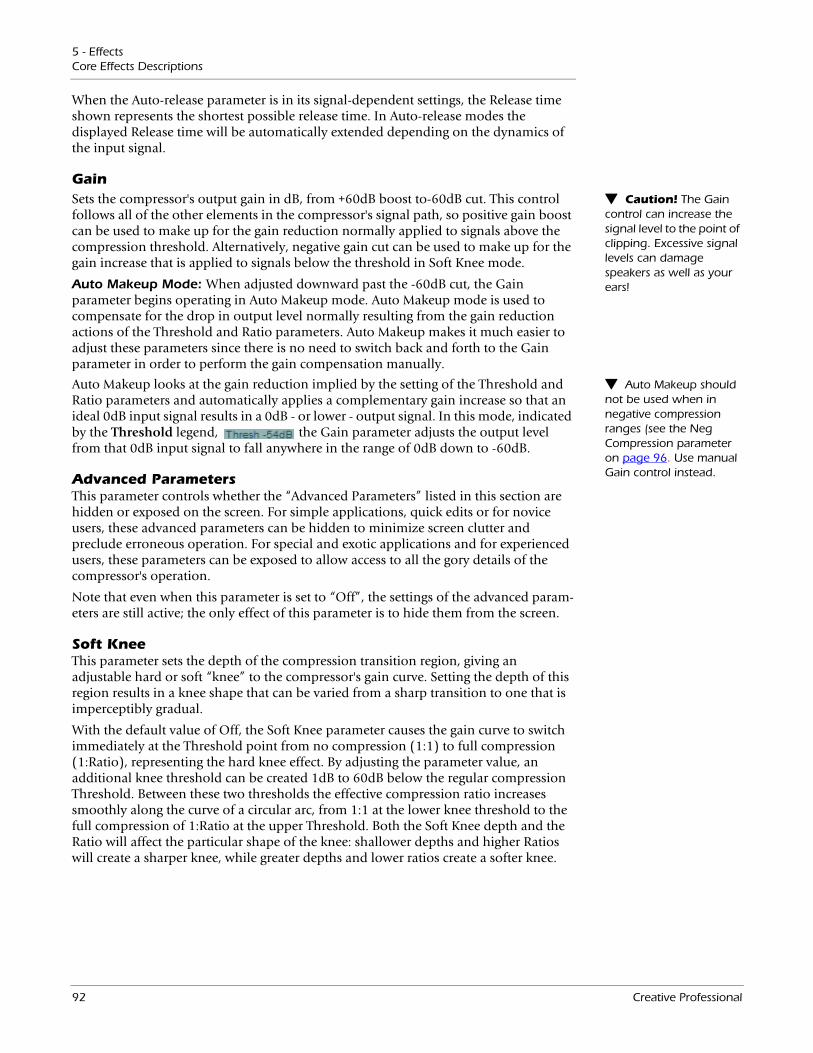
5 - EffectsCore Effects Descriptions
When the Auto-release parameter is in its signal-dependent settings, the Release time shown represents the shortest possible release time. In Auto-release modes the displayed Release time will be automatically extended depending on the dynamics of the input signal.
Gain Caution! The Gain control can increase the signal level to the point of clipping. Excessive signal levels can damage speakers as well as your ears!
Sets the compressor's output gain in dB, from +60dB boost to-60dB cut. This control follows all of the other elements in the compressor's signal path, so positive gain boost can be used to make up for the gain reduction normally applied to signals above the compression threshold. Alternatively, negative gain cut can be used to make up for the gain increase that is applied to signals below the threshold in Soft Knee mode.
Auto Makeup Mode: When adjusted downward past the -60dB cut, the Gain parameter begins operating in Auto Makeup mode. Auto Makeup mode is used to compensate for the drop in output level normally resulting from the gain reduction actions of the Threshold and Ratio parameters. Auto Makeup makes it much easier to adjust these parameters since there is no need to switch back and forth to the Gain parameter in order to perform the gain compensation manually.
Auto Makeup should not be used when in negative compression ranges (see the Neg Compression parameter on page 96. Use manual Gain control instead.
Auto Makeup looks at the gain reduction implied by the setting of the Threshold and Ratio parameters and automatically applies a complementary gain increase so that an ideal 0dB input signal results in a 0dB - or lower - output signal. In this mode, indicated by the Threshold legend, the Gain parameter adjusts the output level from that 0dB input signal to fall anywhere in the range of 0dB down to -60dB.
Advanced ParametersThis parameter controls whether the “Advanced Parameters” listed in this section are hidden or exposed on the screen. For simple applications, quick edits or for novice users, these advanced parameters can be hidden to minimize screen clutter and preclude erroneous operation. For special and exotic applications and for experienced users, these parameters can be exposed to allow access to all the gory details of the compressor's operation.
Note that even when this parameter is set to “Off”, the settings of the advanced param-eters are still active; the only effect of this parameter is to hide them from the screen.
Soft KneeThis parameter sets the depth of the compression transition region, giving an adjustable hard or soft “knee” to the compressor's gain curve. Setting the depth of this region results in a knee shape that can be varied from a sharp transition to one that is imperceptibly gradual.
With the default value of Off, the Soft Knee parameter causes the gain curve to switch immediately at the Threshold point from no compression (1:1) to full compression (1:Ratio), representing the hard knee effect. By adjusting the parameter value, an additional knee threshold can be created 1dB to 60dB below the regular compression Threshold. Between these two thresholds the effective compression ratio increases smoothly along the curve of a circular arc, from 1:1 at the lower knee threshold to the full compression of 1:Ratio at the upper Threshold. Both the Soft Knee depth and the Ratio will affect the particular shape of the knee: shallower depths and higher Ratios will create a sharper knee, while greater depths and lower ratios create a softer knee.
92 Creative Professional
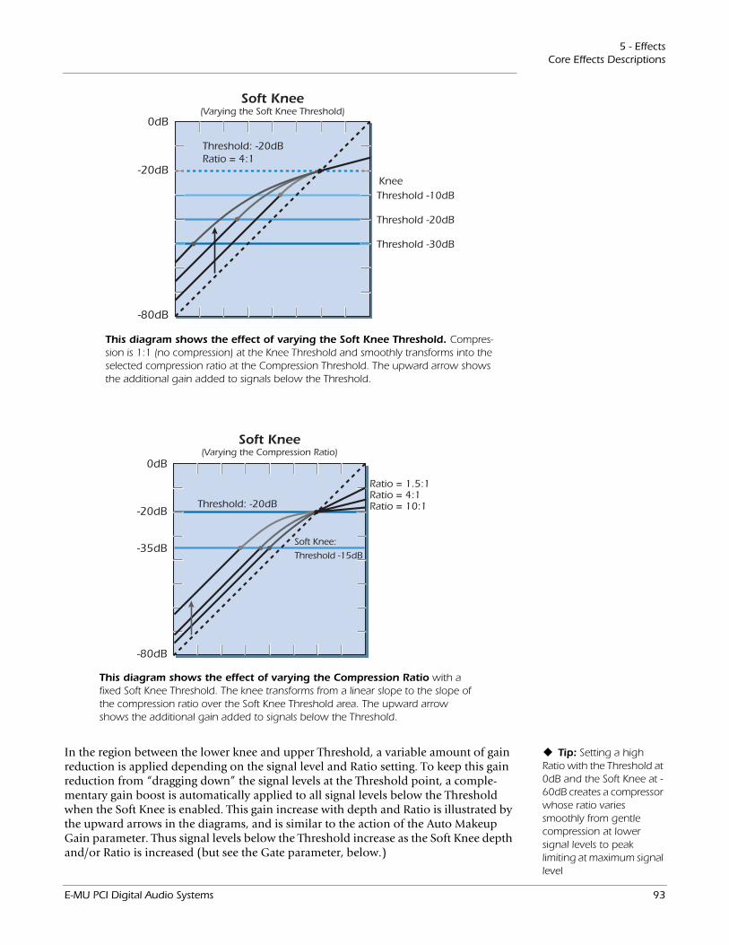
5 - EffectsCore Effects Descriptions
0dB
Threshold -10dB
Threshold -20dB
Threshold -30dB
Knee-20dB
-80dB
Threshold: -20dBRatio = 4:1
Soft Knee(Varying the Soft Knee Threshold)
0dB
Ratio = 1.5:1Ratio = 4:1Ratio = 10:1-20dB
-35dB
-80dB
Threshold: -20dB
Soft Knee(Varying the Compression Ratio)
Soft Knee:
Threshold -15dB
This diagram shows the effect of varying the Soft Knee Threshold. Compres-sion is 1:1 (no compression) at the Knee Threshold and smoothly transforms into the selected compression ratio at the Compression Threshold. The upward arrow shows the additional gain added to signals below the Threshold.
This diagram shows the effect of varying the Compression Ratio with a fixed Soft Knee Threshold. The knee transforms from a linear slope to the slope of the compression ratio over the Soft Knee Threshold area. The upward arrow shows the additional gain added to signals below the Threshold.
Tip: Setting a high Ratio with the Threshold at 0dB and the Soft Knee at -60dB creates a compressor whose ratio varies smoothly from gentle compression at lower signal levels to peak limiting at maximum signal level
In the region between the lower knee and upper Threshold, a variable amount of gain reduction is applied depending on the signal level and Ratio setting. To keep this gain reduction from “dragging down” the signal levels at the Threshold point, a comple-mentary gain boost is automatically applied to all signal levels below the Threshold when the Soft Knee is enabled. This gain increase with depth and Ratio is illustrated by the upward arrows in the diagrams, and is similar to the action of the Auto Makeup Gain parameter. Thus signal levels below the Threshold increase as the Soft Knee depth and/or Ratio is increased (but see the Gate parameter, below.)
E-MU PCI Digital Audio Systems 93
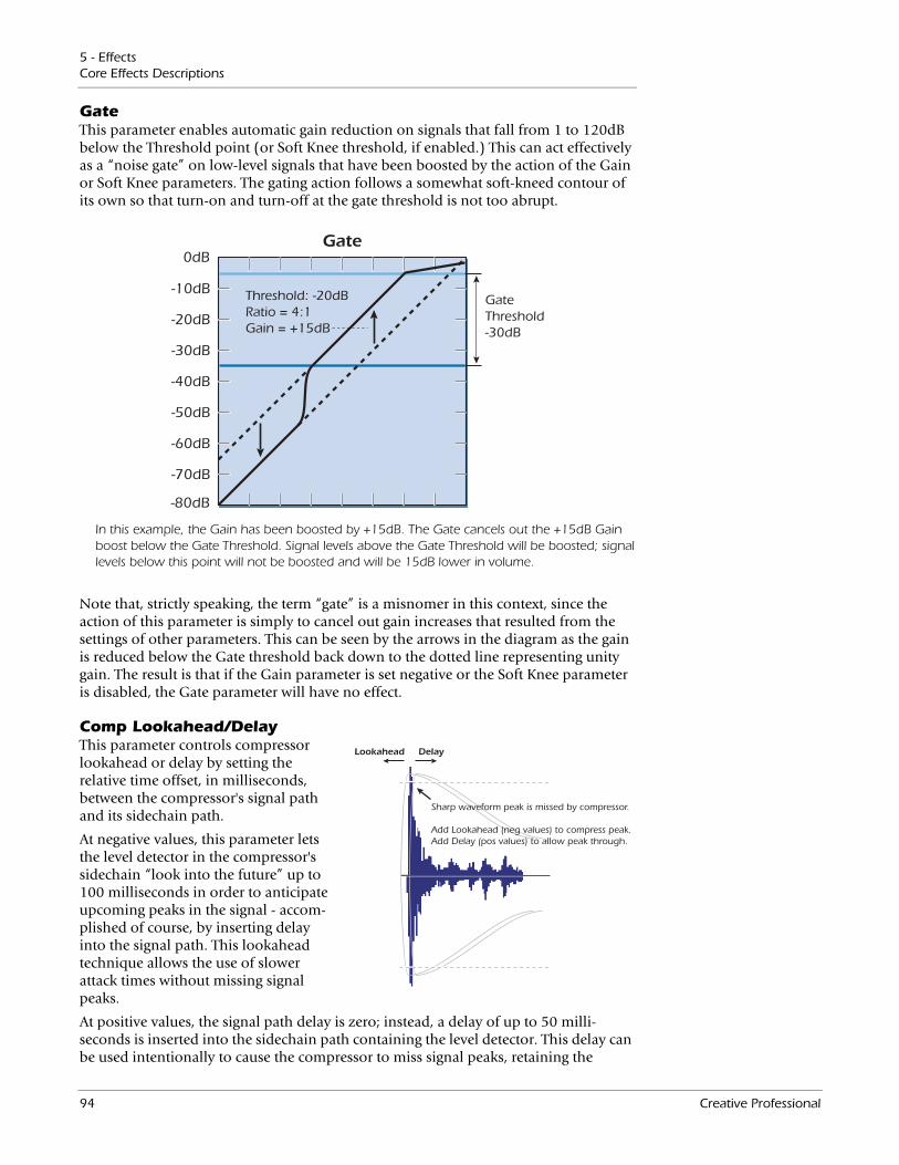
5 - EffectsCore Effects Descriptions
GateThis parameter enables automatic gain reduction on signals that fall from 1 to 120dB below the Threshold point (or Soft Knee threshold, if enabled.) This can act effectively as a “noise gate” on low-level signals that have been boosted by the action of the Gain or Soft Knee parameters. The gating action follows a somewhat soft-kneed contour of its own so that turn-on and turn-off at the gate threshold is not too abrupt.
0dB
-10dB
-20dB
-30dB
-40dB
-50dB
-60dB
-70dB
-80dB
Threshold: -20dBRatio = 4:1Gain = +15dB
Gate
GateThreshold-30dB
In this example, the Gain has been boosted by +15dB. The Gate cancels out the +15dB Gain boost below the Gate Threshold. Signal levels above the Gate Threshold will be boosted; signal levels below this point will not be boosted and will be 15dB lower in volume.
Note that, strictly speaking, the term “gate” is a misnomer in this context, since the action of this parameter is simply to cancel out gain increases that resulted from the settings of other parameters. This can be seen by the arrows in the diagram as the gain is reduced below the Gate threshold back down to the dotted line representing unity gain. The result is that if the Gain parameter is set negative or the Soft Knee parameter is disabled, the Gate parameter will have no effect.
Lookahead Delay
Sharp waveform peak is missed by compressor.
Add Lookahead (neg values) to compress peak.Add Delay (pos values) to allow peak through.
Comp Lookahead/DelayThis parameter controls compressor lookahead or delay by setting the relative time offset, in milliseconds, between the compressor's signal path and its sidechain path.
At negative values, this parameter lets the level detector in the compressor's sidechain “look into the future” up to 100 milliseconds in order to anticipate upcoming peaks in the signal - accom-plished of course, by inserting delay into the signal path. This lookahead technique allows the use of slower attack times without missing signal peaks.
At positive values, the signal path delay is zero; instead, a delay of up to 50 milli-seconds is inserted into the sidechain path containing the level detector. This delay can be used intentionally to cause the compressor to miss signal peaks, retaining the
94 Creative Professional
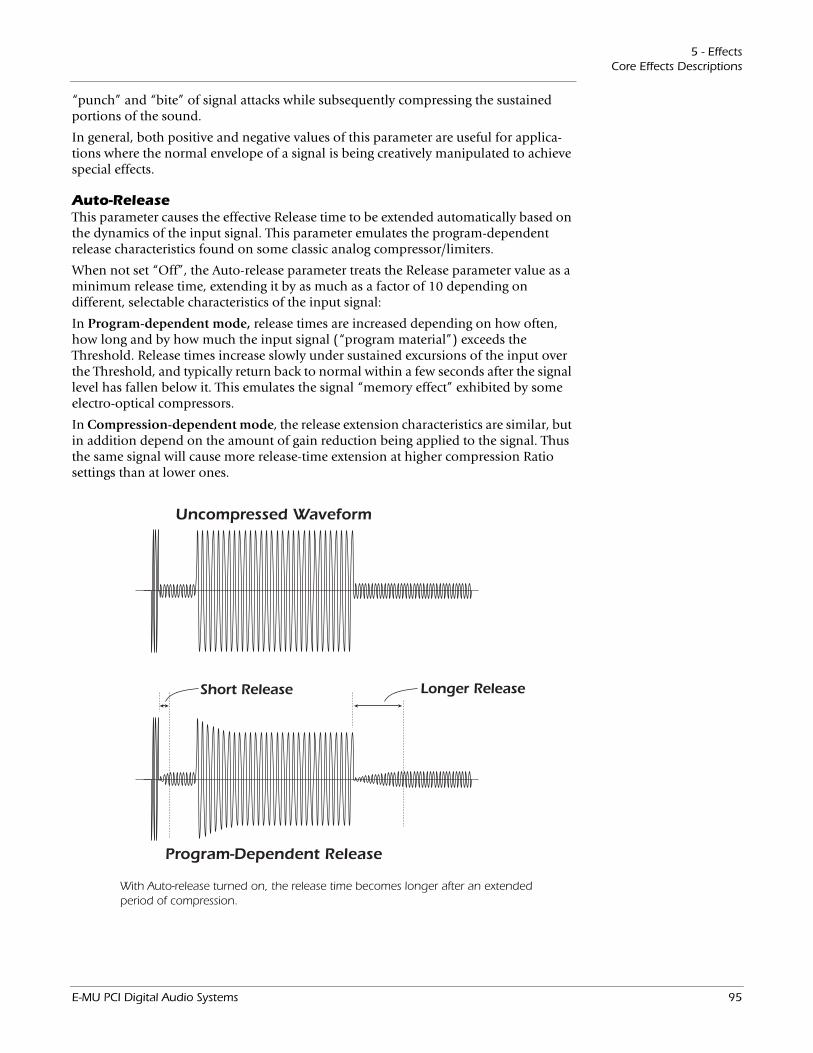
5 - EffectsCore Effects Descriptions
“punch” and “bite” of signal attacks while subsequently compressing the sustained portions of the sound.
In general, both positive and negative values of this parameter are useful for applica-tions where the normal envelope of a signal is being creatively manipulated to achieve special effects.
Auto-ReleaseThis parameter causes the effective Release time to be extended automatically based on the dynamics of the input signal. This parameter emulates the program-dependent release characteristics found on some classic analog compressor/limiters.
When not set “Off”, the Auto-release parameter treats the Release parameter value as a minimum release time, extending it by as much as a factor of 10 depending on different, selectable characteristics of the input signal:
In Program-dependent mode, release times are increased depending on how often, how long and by how much the input signal (“program material”) exceeds the Threshold. Release times increase slowly under sustained excursions of the input over the Threshold, and typically return back to normal within a few seconds after the signal level has fallen below it. This emulates the signal “memory effect” exhibited by some electro-optical compressors.
In Compression-dependent mode, the release extension characteristics are similar, but in addition depend on the amount of gain reduction being applied to the signal. Thus the same signal will cause more release-time extension at higher compression Ratio settings than at lower ones.
Uncompressed Waveform
Program-Dependent Release
Short Release Longer Release
With Auto-release turned on, the release time becomes longer after an extended period of compression.
E-MU PCI Digital Audio Systems 95
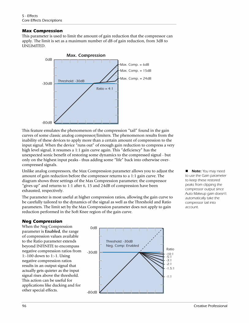
5 - EffectsCore Effects Descriptions
Max CompressionThis parameter is used to limit the amount of gain reduction that the compressor can apply. The limit is set as a maximum number of dB of gain reduction, from 3dB to UNLIMITED.
0dB
-30dB
-80dB
Threshold: -30dB
Max. Compression
Max. Comp. = 6dB
Max. Comp. = 15dB
Max. Comp. = 24dB
Ratio = 4:1
This feature emulates the phenomenon of the compression “tail” found in the gain curves of some classic analog compressor/limiters. The phenomenon results from the inability of these devices to apply more than a certain amount of compression to the input signal. When the device “runs out” of enough gain reduction to compress a very high level signal, it resumes a 1:1 gain curve again. This “deficiency” has the unexpected sonic benefit of restoring some dynamics to the compressed signal - but only on the highest input peaks - thus adding some “life” back into otherwise over-compressed signals.
Note: You may need to use the Gain parameter to keep these restored peaks from clipping the compressor output since Auto Makeup gain doesn't automatically take the compressor tail into account.
Unlike analog compressors, the Max Compression parameter allows you to adjust the amount of gain reduction before the compressor returns to a 1:1 gain curve. The diagram shows three settings of the Max Compression parameter; the compressor “gives up” and returns to 1:1 after 6, 15 and 24dB of compression have been exhausted, respectively.
The parameter is most useful at higher compression ratios, allowing the gain curve to be carefully tailored to the dynamics of the signal as well as the Threshold and Ratio parameters. The limit set by the Max Compression parameter does not apply to gain reduction performed in the Soft Knee region of the gain curve.
0dB
-30dB
-80dB
Threshold: -30dBNeg. Comp: Enabled
-10:1-5:1-3:1-2:1-1.5:1
-1:1
Ratio
Neg CompressionWhen the Neg Compression parameter is Enabled, the range of compression values available to the Ratio parameter extends beyond INFINITE to encompass negative compression ratios from 1:-100 down to 1:-1. Using negative compression ratios results in an output signal that actually gets quieter as the input signal rises above the threshold. This action can be useful for applications like ducking and for other special effects.
96 Creative Professional
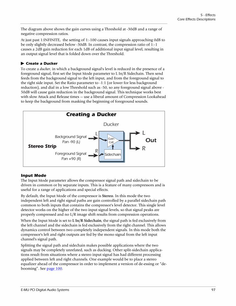
5 - EffectsCore Effects Descriptions
The diagram above shows the gain curves using a Threshold at -30dB and a range of negative compression ratios.
At just past 1:INFINITE, the setting of 1:-100 causes input signals approaching 0dB to be only slightly decreased below -30dB. In contrast, the compression ratio of 1:-1 causes a 2dB gain reduction for each 1dB of additional input signal level, resulting in an output signal level that is folded down over the Threshold.
Create a DuckerTo create a ducker, in which a background signal's level is reduced in the presence of a foreground signal, first set the Input Mode parameter to L In/R Sidechain. Then send feeds from the background signal to the left input, and from the foreground signal to the right side input. Set the Ratio parameter to -1:1 (or lower for less background reduction), and dial in a low Threshold such as -50, so any foreground signal above -50dB will cause gain reduction in the background signal. This technique works best with slow Attack and Release times — use a liberal amount of Compression Lookahead to keep the background from masking the beginning of foreground sounds.
Creating a Ducker
LLOut
RR
Ducker
Sidechain
GainCell
Foreground Signal Pan +90 (R)
Background Signal Pan -90 (L)
Stereo Strip
Input ModeThe Input Mode parameter allows the compressor signal path and sidechain to be driven in common or by separate inputs. This is a feature of many compressors and is useful for a range of applications and special effects.
By default, the Input Mode of the compressor is Stereo. In this mode the two independent left and right signal paths are gain controlled by a parallel sidechain path common to both inputs that contains the compressor's level detector. This single level detector works on the higher of the two input signal levels, so that signal peaks are properly compressed and no L/R image shift results from compression operations.
When the Input Mode is set to L In/R Sidechain, the signal path is fed exclusively from the left channel and the sidechain is fed exclusively from the right channel. This allows dynamics control between two completely independent signals. In this mode both the compressor's left and right outputs are fed by the mono signal from the left input channel's signal path.
Splitting the signal path and sidechain makes possible applications where the two signals may be completely unrelated, such as ducking. Other split-sidechain applica-tions result from situations where a stereo input signal has had different processing applied between left and right channels. One example would be to place a stereo equalizer ahead of the compressor in order to implement a version of de-essing or “de-booming”. See page 100.
E-MU PCI Digital Audio Systems 97

5 - EffectsCore Effects Descriptions
Example SettingsHere we have provided a few examples to show the varied uses of this useful tool. Bear in mind that these examples are simply starting points and that you will undoubtedly need to fine tune the parameters to fit the program material and to suit your own taste.
Increase Drum Punch:Adjust the Threshold control to control the amount of compression.
• Threshold: Adjust so that all hits are being compressed.
• Ratio: 4:1
• Attack: 8 msec (Increase the time to hear more “stick” sound.)
• Release: 60 msec (Adjust according to the tempo of song.)
• Gain: Adjust to make up for lost volume.
• Soft Knee: Adjust as desired.
• Comp. Lookahead: This can be used instead of the Attack control.
• Max. Compression: Unlimited
Smoothing out the Bass Guitar Level:This setup evens out the volume and prevents the bass guitar from wandering in and out of the mix.
• Threshold: -24dB (adjust according to the sound)
• Ratio: 4:1
• Attack: 8 msec
• Release: 70 msec
• Gain: +4dB (adjust according to the sound)
• Soft Knee: Threshold -8dB
• Gate: Off
• Comp. Lookahead: 0 msec
• Auto-release: Comp-dependent
• Max. Compression: 18dB
Peak Limiting:This setup trims only the very loudest peaks, leaving most of the signal intact.
• Threshold: -37dB (adjust according to the sound)
• Ratio: 2:1 or 3:1
• Attack: Instantaneous
• Release: 30 msec
• Gain: 0dB
• Soft Knee: Off
• Gate: Off
• Comp. Lookahead: -5 msec
• Max. Compression: Unlimited
98 Creative Professional
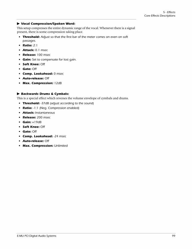
5 - EffectsCore Effects Descriptions
Vocal Compression/Spoken Word:This setup compresses the entire dynamic range of the vocal. Whenever there is a signal present, there is some compression taking place.
• Threshold: Adjust so that the first bar of the meter comes on even on soft passages.
• Ratio: 2:1
• Attack: 0.1 msec
• Release: 100 msec
• Gain: Set to compensate for lost gain.
• Soft Knee: Off
• Gate: Off
• Comp. Lookahead: 0 msec
• Auto-release: Off
• Max. Compression: 12dB
Backwards Drums & Cymbals:This is a special effect which reverses the volume envelope of cymbals and drums.
• Threshold: -37dB (adjust according to the sound)
• Ratio: -1:1 (Neg. Compression enabled)
• Attack: Instantaneous
• Release: 200 msec
• Gain: +19dB
• Soft Knee: Off
• Gate: Off
• Comp. Lookahead: -24 msec
• Auto-release: Off
• Max. Compression: Unlimited
E-MU PCI Digital Audio Systems 99
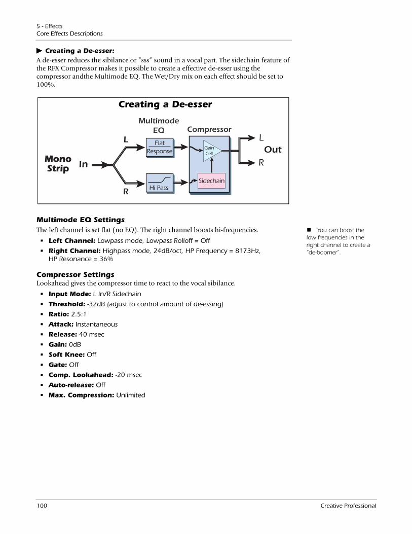
5 - EffectsCore Effects Descriptions
Creating a De-esser:A de-esser reduces the sibilance or “sss” sound in a vocal part. The sidechain feature of the RFX Compressor makes it possible to create a effective de-esser using the compressor andthe Multimode EQ. The Wet/Dry mix on each effect should be set to 100%.
In
L
R
MultimodeEQ Compressor
FlatResponse
Hi PassSidechain
GainCell
LOut
RMonoStrip
Creating a De-esser
Multimode EQ Settings You can boost the
low frequencies in the right channel to create a “de-boomer”.
The left channel is set flat (no EQ). The right channel boosts hi-frequencies.
• Left Channel: Lowpass mode, Lowpass Rolloff = Off
• Right Channel: Highpass mode, 24dB/oct, HP Frequency = 8173Hz, HP Resonance = 36%
Compressor SettingsLookahead gives the compressor time to react to the vocal sibilance.
• Input Mode: L In/R Sidechain
• Threshold: -32dB (adjust to control amount of de-essing)
• Ratio: 2.5:1
• Attack: Instantaneous
• Release: 40 msec
• Gain: 0dB
• Soft Knee: Off
• Gate: Off
• Comp. Lookahead: -20 msec
• Auto-release: Off
• Max. Compression: Unlimited
100 Creative Professional
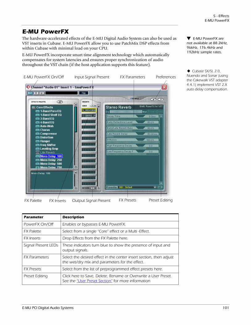
5 - EffectsE-MU PowerFX
E-MU PowerFX E-MU PowerFX are not available at 88.2kHz, 96kHz, 176.4kHz and 192kHz sample rates.
The hardware-accelerated effects of the E-MU Digital Audio System can also be used as VST inserts in Cubase. E-MU PowerFX allow you to use PatchMix DSP effects from within Cubase with minimal load on your CPU.
E-MU PowerFX incorporate smart time alignment technology which automatically compensates for system latencies and ensures proper synchronization of audio throughout the VST chain (if the host application supports this feature).
Input Signal Present
Output Signal Present FX Presets
FX Parameters
FX Palette
E-MU PowerFX On/Off Preferences
Preset EditingFX Inserts
Cubase SX/SL 2.0, Nuendo and Sonar (using the Cakewalk VST adapter 4.4.1) implement VST 2.X auto delay compensation.
Parameter Description
PowerFX On/Off Enables or bypasses E-MU PowerFX.
FX Palette Select from a single “Core” effect or a Multi -Effect.
FX Inserts Drop Effects from the FX Palette here.
Signal Present LEDs These indicators turn blue to show the presence of input and output signals.
FX Parameters Select the desired effect in the center insert section, then adjust the wet/dry mix and parameters for the effect.
FX Presets Select from the list of preprogrammed effect presets here.
Preset Editing Click here to Save, Delete, Rename or Overwrite a User Preset. See the “User Preset Section” for more information
E-MU PCI Digital Audio Systems 101
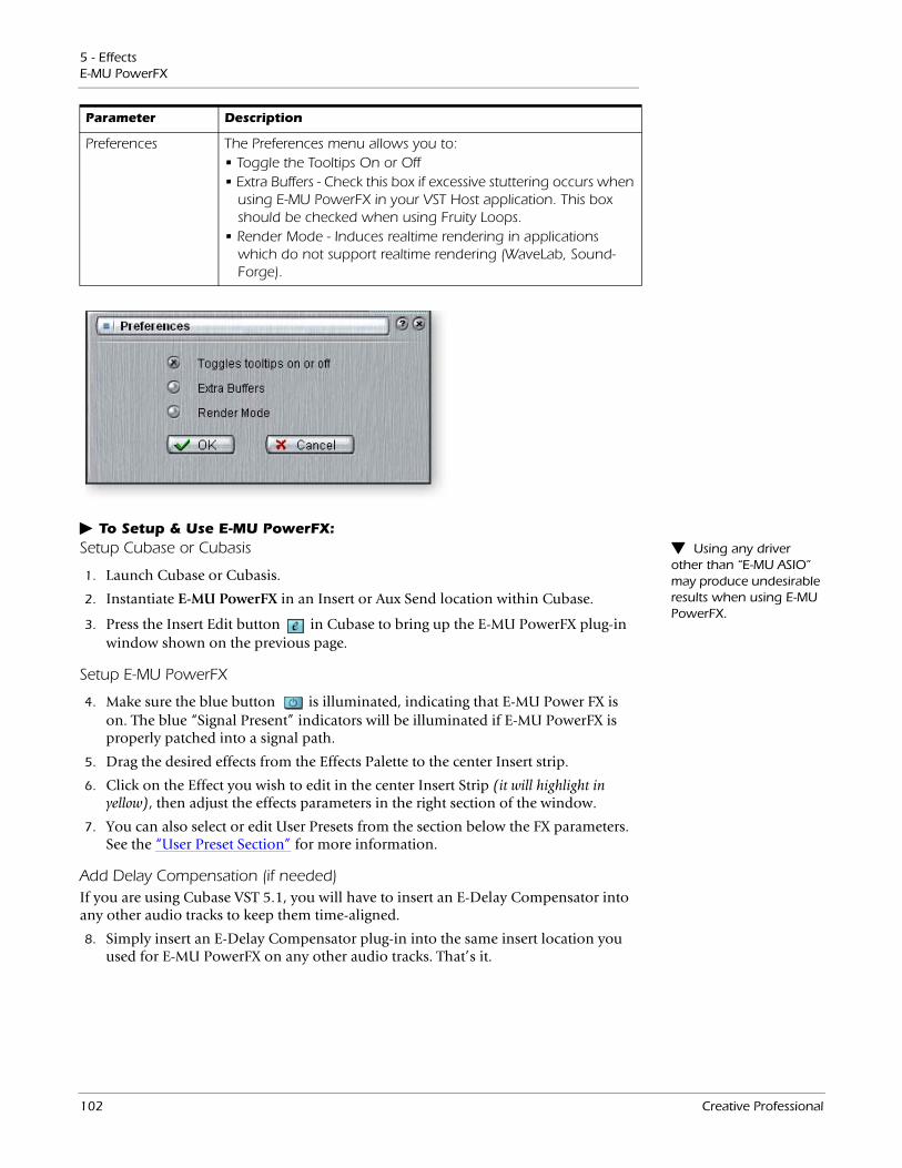
5 - EffectsE-MU PowerFX
To Setup & Use E-MU PowerFX: Using any driver other than “E-MU ASIO” may produce undesirable results when using E-MU PowerFX.
Setup Cubase or Cubasis
1. Launch Cubase or Cubasis.
2. Instantiate E-MU PowerFX in an Insert or Aux Send location within Cubase.
3. Press the Insert Edit button in Cubase to bring up the E-MU PowerFX plug-in window shown on the previous page.
Setup E-MU PowerFX
4. Make sure the blue button is illuminated, indicating that E-MU Power FX is on. The blue “Signal Present” indicators will be illuminated if E-MU PowerFX is properly patched into a signal path.
5. Drag the desired effects from the Effects Palette to the center Insert strip.
6. Click on the Effect you wish to edit in the center Insert Strip (it will highlight in yellow), then adjust the effects parameters in the right section of the window.
7. You can also select or edit User Presets from the section below the FX parameters. See the “User Preset Section” for more information.
Add Delay Compensation (if needed)If you are using Cubase VST 5.1, you will have to insert an E-Delay Compensator into any other audio tracks to keep them time-aligned.
8. Simply insert an E-Delay Compensator plug-in into the same insert location you used for E-MU PowerFX on any other audio tracks. That’s it.
Preferences The Preferences menu allows you to:• Toggle the Tooltips On or Off• Extra Buffers - Check this box if excessive stuttering occurs when
using E-MU PowerFX in your VST Host application. This box should be checked when using Fruity Loops.
• Render Mode - Induces realtime rendering in applications which do not support realtime rendering (WaveLab, Sound-Forge).
Parameter Description
102 Creative Professional

5 - EffectsE-MU PowerFX
Automating E-MU PowerFX Steinberg Cubasis does not have the control automation feature.
E-MU PowerFX can be automated in Cubase LE (or other recording host) just like any other VST effect. When “Write Automation” is activated in Cubase, control changes made in the PowerFX window during playback will be recorded on a special “Automation Subtrack”. When “Automation Read”is activated, the recorded control changes will be played back.
To Record E-MU PowerFX parameter changes in Cubase LE
1. Add E-MU PowerFX as a Channel Insert.
2. Rewind the song and enable “Automation Write” by pressing the WRITE button
on, illuminating it. (Refers to Cubase LE. If you are using another appli-cation, refer to the documentation.)
3. Bring the E-MU PowerFX window to the front and select the Effect you want to automate. The effect parameters appear in the TV screen. Make sure the blue “On” button is lit.
4. Press the Play button on the Cubase Transport control. The song begins playing.
5. Adjust the E-MU PowerFX controls to achieve the effect you want. Rewind the song when finished.
6. Disable “Automation Write” and enable “Automation Read” . Playback the song to hear and view your changes.
Once you have recorded or drawn automation, do not delete or move effects from the Insert Strip. Doing so will result in unpredictable behavior.
7. To edit Automation, first enable both “Automation Write” and “Automation Read” and press Play. Cubase LE begins overwriting as soon as you change a control.
8. If you don’t like the results and want to try again, select Show Used Automation from the Project menu. The Automation Subtrack appears. Next, click in the Parameter Display and select Remove Parameter. Note: This only erases one automation parameter from the Automation Subtrack. To erase multiple control edits, repeat the procedure above. See the Cubase LE manual for more specific information about automation editing.
E-MU PowerFX Resource AvailabilityBecause different collections of VST plug-ins and PatchMix Sessions can be run simul-taneously, it is possible to load a Cubase Song or PatchMix Session for which resources are not available. If DSP resources are NOT available for an existing setup:
• E-MU PowerFX loads a Hardware I/O Path and simply passes audio through without any effects. The effects insert slot(s) in E-MU PowerFX will be “redded out”.
• If no Hardware I/O Paths are available, the plug-in will be disabled and run in a soft pass-through mode. The effects insert slot(s) in E-MU PowerFX will be “grayed out”.
• If DSP resources ARE available, but no Hardware I/O Paths are available, the plug-in will run in soft pass-through mode.
• If the sample rate is changed in the middle of a E-MU PowerFX session, E-MU PowerFX plug-ins will be bypassed, since the hardware effects cannot operate at 88kHz, 96kHz, 176.4kHz or 192kHz.
E-MU PCI Digital Audio Systems 103
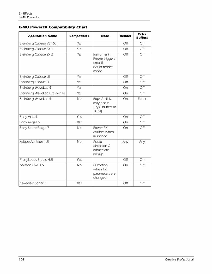
5 - EffectsE-MU PowerFX
E-MU PowerFX Compatibility Chart
Application Name Compatible? Note Render Extra Buffers
Steinberg Cubase VST 5.1 Yes Off Off
Steinberg Cubase SX 1 Yes Off Off
Steinberg Cubase SX 2 Yes Instrument Freeze triggers error if not in render mode.
Off Off
Steinberg Cubase LE Yes Off Off
Steinberg Cubase SL Yes Off Off
Steinberg WaveLab 4 Yes On Off
Steinberg WaveLab Lite (ver 4) Yes On Off
Steinberg WaveLab 5 No Pops & clicks may occur. (Try 8 buffers at 1024)
On Either
Sony Acid 4 Yes On Off
Sony Vegas 5 Yes On Off
Sony SoundForge 7 No Power FX crashes when launched.
On Off
Adobe Audition 1.5 No Audio distortion & immediate lockup.
Any Any
FruityLoops Studio 4.5 Yes Off On
Ableton Live 3.5 No Distortion when FX parameters are changed.
On Off
Cakewalk Sonar 3 Yes Off Off
104 Creative Professional
5 - EffectsRendering Audio with E-MU PowerFX
Rendering Audio with E-MU PowerFXRendering (sometimes called Export) is a mixdown process performed by the host application, which creates a new digital audio file from a multitrack song. Rendering allows a virtually unlimited number of VST effects to be used because the audio processing is performed out of realtime.
E-MU PowerFX and the PatchMix DSP effects are strictly realtime processes. When E-MU PowerFX are used while rendering audio, the rendering process must proceed at realtime rate. Some host applications are not designed to handle realtime rendering and this can cause problems. E-MU PowerFX can be used with these applications if you are willing to follow certain guidelines.
General Tips for Rendering using PowerFX• If an error message occurs, increase the “ASIO Buffer Latency” setting located in
the device Setup dialog box. Depending on your setup, you may have to increase or decrease the Buffer Latency settings to find the setting that works.
• Instead of rendering with E-MU PowerFX, bounce the E-MU PowerFX processed tracks to another track in realtime.
• Check “Realtime Render” in the Render dialog box when using Cubase LE, Cubase SX2 or Cubase SL2. This setting will give the best results.
Tips for using Freeze Mode on Cubase LE• Make the project length as short as possible. Freeze always renders the entire
project length, even if the MIDI track being rendered is shorter.
• Great Tip: Temporarily bypass E-MU PowerFX (and any other effects) even when “Freezing” another track. This will allow the track to Freeze faster than realtime.
Using E-MU PowerFX with WaveLab and SoundForgeStuttering in the audio can occur when rendering with SoundForge or any version of Steinberg WaveLab. This problem is caused by discontinuities in the first few audio buffers as they are fed by WaveLab to E-MU PowerFX. The problem can be eliminated by following these guidelines.
• Check “Render Mode” box in the E-MU PowerFX preferences. See page 102.
• We recommend that you only use the MME/WAVE E-DSP Wave [xxxx] drivers.
• Reduce the “Buffer Size” in the WaveLab, Audio Preferences dialog box. This moves the stuttering to beginning of the file.
• Pad the beginning (and/or end) of your audio file with silence (.5 to several seconds depending on the file). This action causes the buffer discontinuities to occur before the song begins.
E-MU PCI Digital Audio Systems 105
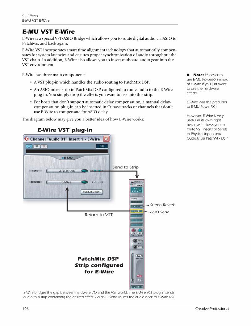
5 - EffectsE-MU VST E-Wire
E-MU VST E-WireE-Wire is a special VST/ASIO Bridge which allows you to route digital audio via ASIO to PatchMix and back again.
E-Wire VST incorporates smart time alignment technology that automatically compen-sates for system latencies and ensures proper synchronization of audio throughout the VST chain. In addition, E-Wire also allows you to insert outboard audio gear into the VST environment.
Note: It’s easier to use E-MU PowerFX instead of E-Wire if you just want to use the hardware effects. (E-Wire was the precursor to E-MU PowerFX.) However, E-Wire is very useful in its own right because it allows you to route VST inserts or Sends to Physical Inputs and Outputs via PatchMix DSP.
E-Wire has three main components:
• A VST plug-in which handles the audio routing to PatchMix DSP.
• An ASIO mixer strip in PatchMix DSP configured to route audio to the E-Wire plug-in. You simply drop the effects you want to use into this strip.
• For hosts that don’t support automatic delay compensation, a manual delay-compensation plug-in can be inserted in Cubase tracks or channels that don’t use E-Wire to compensate for ASIO delay.
Stereo Reverb
ASIO Send
E-Wire VST plug-in
PatchMix DSP Strip configured
for E-Wire
Send to Strip
Return to VST
E-Wire bridges the gap between hardware I/O and the VST world. The E-Wire VST plug-in sends audio to a strip containing the desired effect. An ASIO Send routes the audio back to E-Wire VST.
The diagram below may give you a better idea of how E-Wire works:
106 Creative Professional
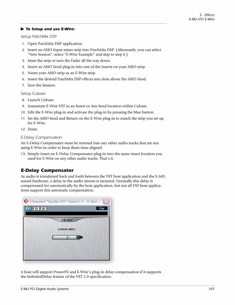
5 - EffectsE-MU VST E-Wire
To Setup and use E-Wire:
Setup PatchMix DSP
1. Open PatchMix DSP application.
2. Insert an ASIO Input mixer strip into PatchMix DSP. (Alternately, you can select “New Session”, select “E-Wire Example” and skip to step 6.)
3. Mute the strip or turn the Fader all the way down.
4. Insert an ASIO Send plug-in into one of the inserts on your ASIO strip.
5. Name your ASIO strip as an E-Wire strip.
6. Insert the desired PatchMix DSP effects into slots above the ASIO Send.
7. Save the Session.
Setup Cubase
8. Launch Cubase.
9. Instantiate E-Wire VST in an Insert or Aux Send location within Cubase.
10. Edit the E-Wire plug-in and activate the plug-in by pressing the blue button.
11. Set the ASIO Send and Return on the E-Wire plug-in to match the strip you set up for E-Wire.
12. Done.
E-Delay CompensationAn E-Delay Compensator must be inserted into any other audio tracks that are not using E-Wire in order to keep them time-aligned.
13. Simply insert an E-Delay Compensator plug-in into the same insert location you used for E-Wire on any other audio tracks. That’s it.
E-Delay CompensatorAs audio is transferred back and forth between the VST host application and the E-MU sound hardware, a delay in the audio stream is incurred. Normally this delay is compensated for automatically by the host application, but not all VST host applica-tions support this automatic compensation.
A host will support PowerFX and E-Wire’s plug-in delay compensation if it supports the SetInitialDelay feature of the VST 2.0 specification.
E-MU PCI Digital Audio Systems 107
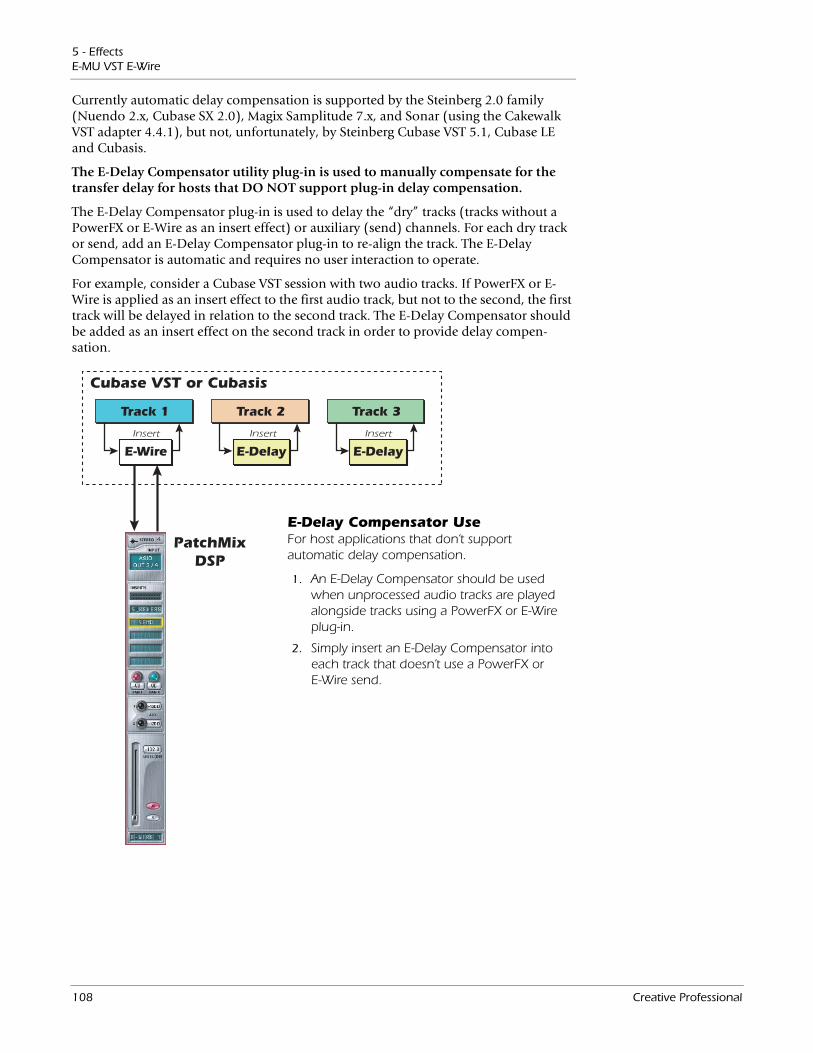
5 - EffectsE-MU VST E-Wire
Currently automatic delay compensation is supported by the Steinberg 2.0 family (Nuendo 2.x, Cubase SX 2.0), Magix Samplitude 7.x, and Sonar (using the Cakewalk VST adapter 4.4.1), but not, unfortunately, by Steinberg Cubase VST 5.1, Cubase LE and Cubasis.
Track 1
Cubase VST or Cubasis
PatchMixDSP
E-Wire
Track 2
E-Delay E-Delay
Track 3
Insert InsertInsert
E-Delay Compensator UseFor host applications that don’t support automatic delay compensation.
1. An E-Delay Compensator should be used when unprocessed audio tracks are played alongside tracks using a PowerFX or E-Wire plug-in.
2. Simply insert an E-Delay Compensator into each track that doesn’t use a PowerFX or E-Wire send.
The E-Delay Compensator utility plug-in is used to manually compensate for the transfer delay for hosts that DO NOT support plug-in delay compensation.
The E-Delay Compensator plug-in is used to delay the “dry” tracks (tracks without a PowerFX or E-Wire as an insert effect) or auxiliary (send) channels. For each dry track or send, add an E-Delay Compensator plug-in to re-align the track. The E-Delay Compensator is automatic and requires no user interaction to operate.
For example, consider a Cubase VST session with two audio tracks. If PowerFX or E-Wire is applied as an insert effect to the first audio track, but not to the second, the first track will be delayed in relation to the second track. The E-Delay Compensator should be added as an insert effect on the second track in order to provide delay compen-sation.
108 Creative Professional
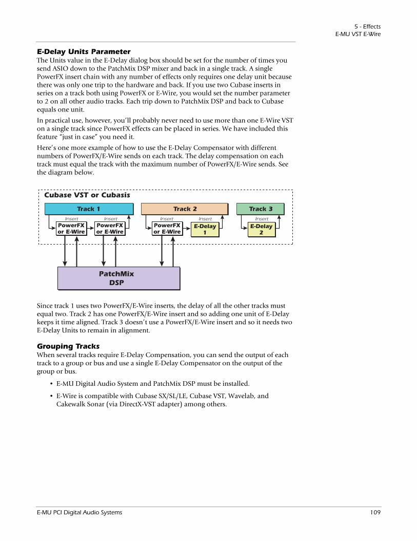
5 - EffectsE-MU VST E-Wire
E-Delay Units ParameterThe Units value in the E-Delay dialog box should be set for the number of times you send ASIO down to the PatchMix DSP mixer and back in a single track. A single PowerFX insert chain with any number of effects only requires one delay unit because there was only one trip to the hardware and back. If you use two Cubase inserts in series on a track both using PowerFX or E-Wire, you would set the number parameter to 2 on all other audio tracks. Each trip down to PatchMix DSP and back to Cubase equals one unit.
In practical use, however, you’ll probably never need to use more than one E-Wire VST on a single track since PowerFX effects can be placed in series. We have included this feature “just in case” you need it.
Here’s one more example of how to use the E-Delay Compensator with different numbers of PowerFX/E-Wire sends on each track. The delay compensation on each track must equal the track with the maximum number of PowerFX/E-Wire sends. See the diagram below.
Track 1
Cubase VST or Cubasis
PowerFXor E-Wire
PowerFXor E-Wire
Track 2
E-Delay1
Track 3
InsertInsertInsert Insert Insert
PowerFXor E-Wire
PatchMixDSP
E-Delay2
Since track 1 uses two PowerFX/E-Wire inserts, the delay of all the other tracks must equal two. Track 2 has one PowerFX/E-Wire insert and so adding one unit of E-Delay keeps it time aligned. Track 3 doesn’t use a PowerFX/E-Wire insert and so it needs two E-Delay Units to remain in alignment.
Grouping TracksWhen several tracks require E-Delay Compensation, you can send the output of each track to a group or bus and use a single E-Delay Compensator on the output of the group or bus.
• E-MU Digital Audio System and PatchMix DSP must be installed.
• E-Wire is compatible with Cubase SX/SL/LE, Cubase VST, Wavelab, and Cakewalk Sonar (via DirectX-VST adapter) among others.
E-MU PCI Digital Audio Systems 109

5 - EffectsE-MU VST E-Wire
110 Creative Professional
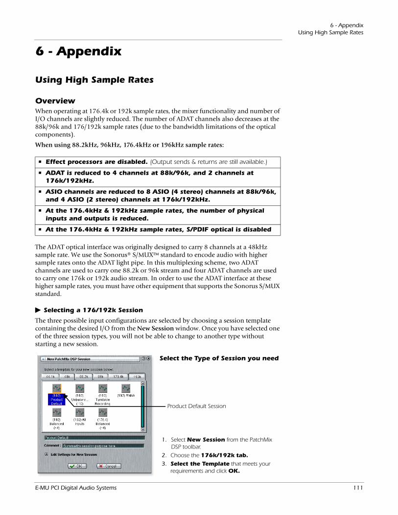
6 - AppendixUsing High Sample Rates
6 - Appendix
Using High Sample Rates
OverviewWhen operating at 176.4k or 192k sample rates, the mixer functionality and number of I/O channels are slightly reduced. The number of ADAT channels also decreases at the 88k/96k and 176/192k sample rates (due to the bandwidth limitations of the optical components).
When using 88.2kHz, 96kHz, 176.4kHz or 196kHz sample rates:
• Effect processors are disabled. (Output sends & returns are still available.)
• ADAT is reduced to 4 channels at 88k/96k, and 2 channels at 176k/192kHz.
• ASIO channels are reduced to 8 ASIO (4 stereo) channels at 88k/96k, and 4 ASIO (2 stereo) channels at 176k/192kHz.
• At the 176.4kHz & 192kHz sample rates, the number of physical inputs and outputs is reduced.
• At the 176.4kHz & 192kHz sample rates, S/PDIF optical is disabled
The ADAT optical interface was originally designed to carry 8 channels at a 48kHz sample rate. We use the Sonorus® S/MUX™ standard to encode audio with higher sample rates onto the ADAT light pipe. In this multiplexing scheme, two ADAT channels are used to carry one 88.2k or 96k stream and four ADAT channels are used to carry one 176k or 192k audio stream. In order to use the ADAT interface at these higher sample rates, you must have other equipment that supports the Sonorus S/MUX standard.
Selecting a 176/192k Session
Product Default Session
Select the Type of Session you need
1. Select New Session from the PatchMix DSP toolbar.
2. Choose the 176k/192k tab.3. Select the Template that meets your
requirements and click OK.
The three possible input configurations are selected by choosing a session template containing the desired I/O from the New Session window. Once you have selected one of the three session types, you will not be able to change to another type without starting a new session.
E-MU PCI Digital Audio Systems 111
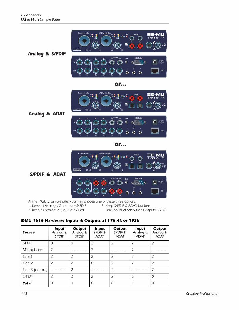
6 - AppendixUsing High Sample Rates
E-MU 1616 Hardware Inputs & Outputs at 176.4k or 192k
SourceInput
Analog & SPDIF
OutputAnalog &
SPDIF
InputSPDIF & ADAT
OutputSPDIF & ADAT
InputAnalog &
ADAT
OutputAnalog &
ADAT
ADAT 0 0 2 2 2 2
Microphone 2 - - - - - - - - 2 - - - - - - - - 2 - - - - - - - -
Line 1 2 2 2 2 2 2
Line 2 2 2 0 2 2 2
Line 3 (output) - - - - - - - - 2 - - - - - - - - 2 - - - - - - - - 2
S/PDIF 2 2 2 2 0 0
Total 8 8 8 8 8 8
or...
or...
&
&
&
At the 192kHz sample rate, you may choose one of these three options:1. Keep all Analog I/O, but lose S/PDIF 3. Keep S/PDIF & ADAT, but lose 2. Keep all Analog I/O, but lose ADAT Line Inputs 2L/2R & Line Outputs 3L/3R
112 Creative Professional
6 - AppendixUsing High Sample Rates
WDM Recording and Playback BehaviorWDM recording and playback is supported at all PatchMix sample rates. The behavior of the driver with respect to PatchMix sample rate is described below.
When PatchMix and the WDM audio content (.WAV file format, playback and record settings in WaveLab. etc.) are both running at the same sample rate, and when a Wave strip or send is present in the PatchMix mixer configuration, WDM audio will be played or recorded “bit accurate” without sample rate conversion or bit truncation.
When running PatchMix at 44kHz/48kHz, if there is a mismatch between the WDM playback audio content and the PatchMix sample rate, sample rate conversion is performed, so that WDM audio will always be heard or recorded. Also, such non-native-sample-rate audio is truncated to 16-bits.
When running PatchMix at the higher sample rates of 88.2kHz, 96kHz, 176.4kHz or 192kHz, WDM record or playback audio content must be running at the same sample rate as PatchMix. If the sample rates are mismatched, NO AUDIO will be produced or recorded. In other words, the WDM driver does not perform sample rate conversion of any kind when PatchMix is running at 88.2kHz, 96kHz, 176.4kHz or 192kHz.
E-MU PCI Digital Audio Systems 113
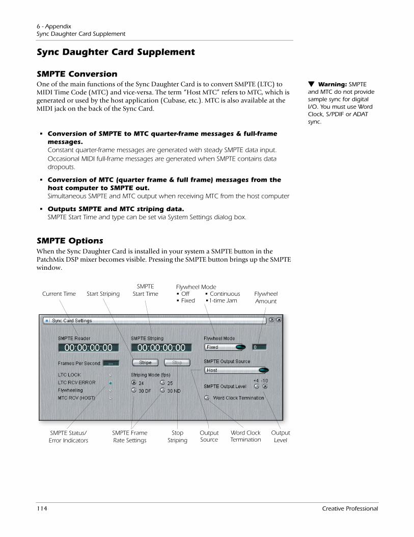
6 - AppendixSync Daughter Card Supplement
Sync Daughter Card Supplement
SMPTE Conversion Warning: SMPTE and MTC do not provide sample sync for digital I/O. You must use Word Clock, S/PDIF or ADAT sync.
One of the main functions of the Sync Daughter Card is to convert SMPTE (LTC) to MIDI Time Code (MTC) and vice-versa. The term “Host MTC” refers to MTC, which is generated or used by the host application (Cubase, etc.). MTC is also available at the MIDI jack on the back of the Sync Card.
• Conversion of SMPTE to MTC quarter-frame messages & full-frame messages.Constant quarter-frame messages are generated with steady SMPTE data input.Occasional MIDI full-frame messages are generated when SMPTE contains data dropouts.
• Conversion of MTC (quarter frame & full frame) messages from the host computer to SMPTE out.Simultaneous SMPTE and MTC output when receiving MTC from the host computer
• Outputs SMPTE and MTC striping data.SMPTE Start Time and type can be set via System Settings dialog box.
SMPTE OptionsWhen the Sync Daughter Card is installed in your system a SMPTE button in the PatchMix DSP mixer becomes visible. Pressing the SMPTE button brings up the SMPTE window.
SMPTE Frame Rate Settings
SMPTE Start Time
SMPTE Status/Error Indicators
Start Striping
StopStriping
Output Level
Flywheel Amount
Flywheel Mode • Off • Continuous • Fixed •1-time Jam
Current Time
OutputSource
Word Clock Termination
114 Creative Professional
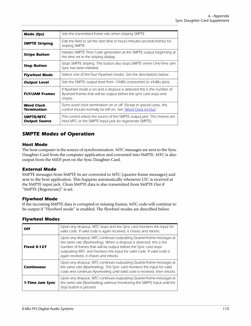
6 - AppendixSync Daughter Card Supplement
Mode (fps) Sets the transmitted frame rate when striping SMPTE.
SMPTE StripingEdit this field to set the start time in hours:minutes:seconds:frames for striping SMPTE.
Stripe ButtonInitiates SMPTE Time Code generation at the SMPTE output beginning at the time set in the striping display.
Stop ButtonStops SMPTE striping. This button also stops SMPTE when One-Time Jam Sync has been initiated.
Flywheel Mode Selects one of the four Flywheel modes. See the descriptions below.
Output Level Sets the SMPTE output level from -10dBV (consumer) to +4dBu (pro).
FLY/JAM FramesIf flywheel mode is on and a dropout is detected this is the number of flywheel frames that will be output before the sync card stops and chases.
Word Clock Termination
Turns word clock termination on or off. Except in special cases, this control should normally be left on. See “Word Clock In/Out”.
SMPTE/MTC Output Source
This control selects the source of the SMPTE output jack. The choices are: Host MTC or the SMPTE Input jack (to regenerate SMPTE).
SMPTE Modes of Operation
Host ModeThe host computer is the source of synchronization. MTC messages are sent to the Sync Daughter Card from the computer application and converted into SMPTE. MTC is also output from the MIDI port on the Sync Daughter Card.
External ModeSMPTE messages from SMPTE In are converted to MTC (quarter-frame messages) and sent to the host application. This happens automatically whenever LTC is received at the SMPTE input jack. Clean SMPTE data is also transmitted from SMPTE Out if “SMPTE (Regenerate)” is set.
Flywheel ModeIf the incoming SMPTE data is corrupted or missing frames, MTC code will continue to be output if “Flywheel mode” is enabled. The flywheel modes are described below.
Flywheel Modes
OffUpon any dropout, MTC stops and the Sync card monitors the input for valid code. If valid code is again received, it chases and relocks.
Fixed 0-127
Upon any dropout, MTC continues outputting Quarter-frame messages at the same rate (flywheeling). When a dropout is detected, this is the number of frames that will be output before the Sync card stops outputting MTC and monitors the input for valid code. If valid code is again received, it chases and relocks.
ContinuousUpon any dropout, MTC continues outputting Quarter-frame messages at the same rate (flywheeling). The Sync card monitors the input for valid code and continues flywheeling until valid code is received, then relocks.
1-Time Jam SyncUpon any dropout, MTC continues outputting Quarter-frame messages at the same rate (flywheeling) without monitoring the SMPTE input until the Stop button is pressed.
E-MU PCI Digital Audio Systems 115
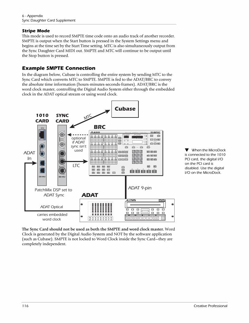
6 - AppendixSync Daughter Card Supplement
Stripe ModeThis mode is used to record SMPTE time code onto an audio track of another recorder. SMPTE is output when the Start button is pressed in the System Settings menu and begins at the time set by the Start Time setting. MTC is also simultaneously output from the Sync Daughter Card MIDI out. SMPTE and MTC will continue to be output until the Stop button is pressed.
Example SMPTE ConnectionIn the diagram below, Cubase is controlling the entire system by sending MTC to the Sync Card which converts MTC to SMPTE. SMPTE is fed to the ADAT/BRC to convey the absolute time information (hours-minutes-seconds-frames). ADAT/BRC is the word clock master, controlling the Digital Audio System either through the embedded clock in the ADAT optical stream or using word clock.
When the MicroDock is connected to the 1010 PCI card, the digital I/O on the PCI card is disabled. Use the digital I/O on the MicroDock.
SYNCCARD
1010CARD
ADAT Optical
carries embeddedword clock
EDI
ADATIn
LTC
BRC
ADAT
REWIND FAST FWD STOP PLAY RECORD EJECT
MTC
PatchMix DSP set to ADAT Sync
1
33
65
97
2
34
66
98
3
35
67
99
4
36
68
100
5
37
69
101
6
38
70
102
7
39
71
103
8
40
72
104
RECORDINPUT
9
41
73
105
10
42
74
106
11
43
75
107
12
44
76
108
13
45
77
109
14
46
78
110
15
47
79
111
16
48
80
112
RECORDINPUT
17
49
81
113
18
50
82
114
19
51
83
115
20
52
84
116
21
53
85
117
22
54
86
118
23
55
87
119
24
56
88
120
RECORDINPUT
25
57
89
121
26
58
90
122
27
59
91
123
28
60
92
124
29
61
93
125
30
62
94
126
31
63
95
127
32
64
96
128
RECORDINPUT
TRACK 1-32 TRACK 33-64 TRACK 65-96 TRACK 97-128
AUTO INPUT ALL SAFE ALL INPUT ALL CLEAR
GROUP 1 GROUP 2 GROUP 3 GROUP 4 SET GROUP LOCATE
SET LOCATE
LOCATE 0
SET LOCATELOCATE SONGLOAD SETUPFROM TAPE
COPY SONGDELETE SONGSAVE SETUP
TO TAPE
MIDI UTIL
PITCH MODE
PITCH DOWN
PITCH UP
NAME
SMPTE IN MIDI IN
FIXED VARIABLE
HOURS MINUTES SECONDS FRAMESCENTS
PITCH MODE
PITCH CONTROL TAPE LOCATION
CURSOR
AUTO-PUNCH
SMPTESMPTE START
OFFSET EXT SYNC
DISPLAY MODE RESET 0 FORMAT TAPE
DISPLAY TYPE EJECT
PRE-ROLL POST-ROLL
LOOP TAPE OFFSETTRACK DELAY
DIGITAL I/O
AUTO PLAY REHEARSE
GEN SYNC EDIT
COPY TAPELOCATION
7STUV
8WXYZ
0(CHARS)
4JKL
5MNO
6PQR
1ABC
2DEF
3GHI
TEMPO MAPRECORD XFADE
NORMAL
SMPTE
BARS
BARS BEATS SUB BEATS ABSOLUTE
RELATIVEE
DROP FRAME
30 FPS
29.97 FPS
25 FPS
24 FPS
M A S T E R R E M O T E C O N T R O L
RECORDPLAYSTOPFAST FORWARDREWIND
ADAT 9-pin
optionalif ADAT
sync isn'tused
Cubase
The Sync Card should not be used as both the SMPTE and word clock master. Word Clock is generated by the Digital Audio System and NOT by the software application (such as Cubase). SMPTE is not locked to Word Clock inside the Sync Card—they are completely independent.
116 Creative Professional
6 - AppendixMIDI Time Code (MTC)
MIDI Time Code (MTC) MTC and SMPTE do NOT synchronize at the sample rate and are not locked to word clock in any way. SMPTE and MTC are used to synchronize music but do not have the required resolution to sample-lock digital audio.
MIDI time code is basically SMPTE time code adapted to the world of MIDI. MTC specifies “absolute” location information in hours:minutes:seconds:frames, just like SMPTE. There are two main kinds of messages in MTC: Full-frame messages and Quarter-frame messages.
Full-frame messages are ten bytes long and are sent when SMPTE start, stops, or relocates. Full-frame messages contain the entire SMPTE number of, hours, minutes, seconds, frames, as well as the SMPTE type: 24fps, 25fps, 30fps non-drop, 30fps drop.
Quarter-frame messages are sent at each quarter of a SMPTE frame and only carry 1/8th of the SMPTE time message. Quarter-frame messages require two entire SMPTE frames to send the complete time stamp (h:m:s:f). Timing accuracy is maintained as long as the quarter-frame messages continue to come in at a constant rate.
To Enable MTC:MIDI Time code disables the use of MIDI port 2 on the MicroDock
1. Open Session Settings from the toolbar.
2. Select the MIDI tab and choose Sync Card/MTC from the MIDI options.
3. Click OK to close the window.Since it is important to have a stable timing reference for your song or sequence, we have given MTC its own MIDI output port on the Sync Daughter Card. This ensures that the timing information will not be affected by other MIDI data on the line.
Important Note: When the Sync Card is installed, MIDI 2 on the MicroDock is disabled. (This is because MTC is using the MIDI port.)
Word Clock In/OutWord clock, ADAT and
S/PDIF synchronize at the sample rate and are used to transfer digital data between machines.
Word clock provides a standardized means of synchronizing multiple digital audio devices so that data can be transferred digitally. In order to digitally transfer from one device to another, the two devices MUST be synchronized. Clicks and pops in the audio will result when transferring digital audio which is not synchronized.
The E-MU 1010 PCI card can be externally clocked from the ADAT input, S/PDIF input or from the Sync Daughter card (if installed). In a digital studio, all digital devices in the system should run off the same master Word Clock.
To Synchronize PatchMix DSP to an External Clock Source:
1. Make sure an external clock source is connected to the E-MU Digital Audio System hardware via the word clock, ADAT or S/PDIF input.
2. Open the Session Settings dialog box.
3. Under the System tab, select External Source, then select either word clock, ADAT or S/PDIF.
4. Press OK to close the dialog box.
5. Check the Sync section of PatchMix DSP to verify that the Locked indicator is illuminated.
Devices can be connected in daisy chain fashion (word clock out connected to the next unit’s word clock in) or in parallel for one or two devices, but professional digital studios normally use a master word clock generator or “House Sync” with a distri-bution system so that each device receives a phase-coherent and jitter-free word clock.
E-MU PCI Digital Audio Systems 117
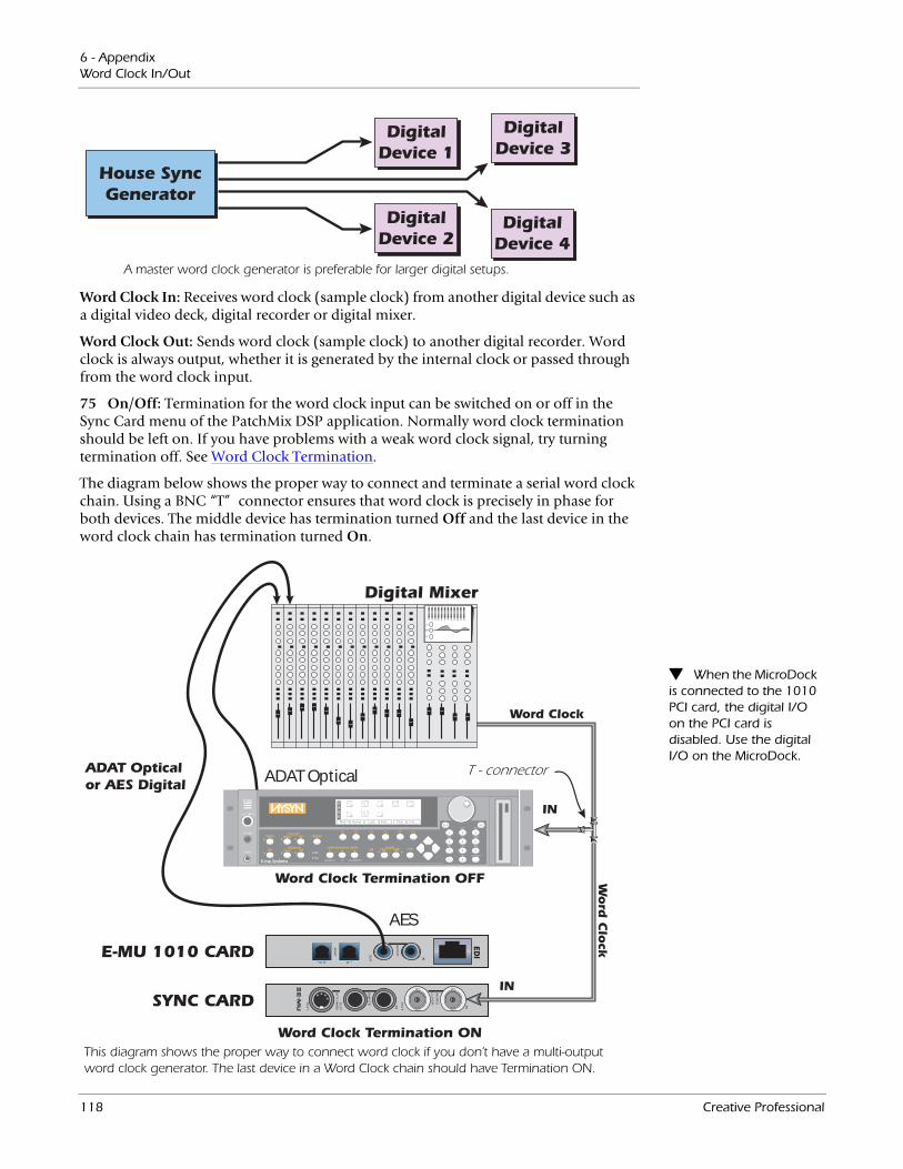
6 - AppendixWord Clock In/Out
House SyncGenerator
DigitalDevice 1
DigitalDevice 2
DigitalDevice 3
DigitalDevice 4
A master word clock generator is preferable for larger digital setups.
Word
Clo
ck
Word Clock
Word Clock Termination ON
Word Clock Termination OFF
SYNC CARD
E-MU 1010 CARD
IN
Digital Mixer
ADAT Opticalor AES Digital
EDI
IN
T - connector
AES
ADAT Optical
This diagram shows the proper way to connect word clock if you don’t have a multi-output word clock generator. The last device in a Word Clock chain should have Termination ON.
Word Clock In: Receives word clock (sample clock) from another digital device such as a digital video deck, digital recorder or digital mixer.
Word Clock Out: Sends word clock (sample clock) to another digital recorder. Word clock is always output, whether it is generated by the internal clock or passed through from the word clock input.
75 On/Off: Termination for the word clock input can be switched on or off in the Sync Card menu of the PatchMix DSP application. Normally word clock termination should be left on. If you have problems with a weak word clock signal, try turning termination off. See Word Clock Termination.
The diagram below shows the proper way to connect and terminate a serial word clock chain. Using a BNC “T”connector ensures that word clock is precisely in phase for both devices. The middle device has termination turned Off and the last device in the word clock chain has termination turned On.
When the MicroDock is connected to the 1010 PCI card, the digital I/O on the PCI card is disabled. Use the digital I/O on the MicroDock.
118 Creative Professional
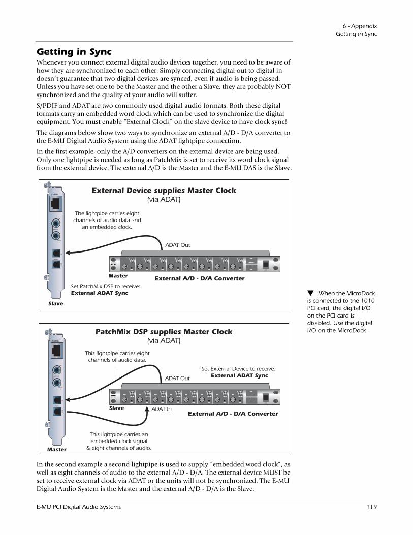
6 - AppendixGetting in Sync
Getting in SyncWhenever you connect external digital audio devices together, you need to be aware of how they are synchronized to each other. Simply connecting digital out to digital in doesn’t guarantee that two digital devices are synced, even if audio is being passed. Unless you have set one to be the Master and the other a Slave, they are probably NOT synchronized and the quality of your audio will suffer.
S/PDIF and ADAT are two commonly used digital audio formats. Both these digital formats carry an embedded word clock which can be used to synchronize the digital equipment. You must enable “External Clock” on the slave device to have clock sync!
The diagrams below show two ways to synchronize an external A/D - D/A converter to the E-MU Digital Audio System using the ADAT lightpipe connection.
In the first example, only the A/D converters on the external device are being used. Only one lightpipe is needed as long as PatchMix is set to receive its word clock signal from the external device. The external A/D is the Master and the E-MU DAS is the Slave.
When the MicroDock is connected to the 1010 PCI card, the digital I/O on the PCI card is disabled. Use the digital I/O on the MicroDock.
1 2 3 4 5 6 7 8
(;7(51$/
Set External Device to receive: External ADAT SyncADAT Out
ADAT In
PatchMix DSP supplies Master Clock(via ADAT)
1 2 3 4 5 6 7 8
Set PatchMix DSP to receive: External ADAT Sync
ADAT Out
External Device supplies Master Clock(via ADAT)
This lightpipe carries anembedded clock signal
& eight channels of audio.
The lightpipe carries eightchannels of audio data and
an embedded clock.
This lightpipe carries eightchannels of audio data.
Master
Slave
Master External A/D - D/A Converter
External A/D - D/A Converter
Slave
(;7(51$/
In the second example a second lightpipe is used to supply “embedded word clock”, as well as eight channels of audio to the external A/D - D/A. The external device MUST be set to receive external clock via ADAT or the units will not be synchronized. The E-MU Digital Audio System is the Master and the external A/D - D/A is the Slave.
E-MU PCI Digital Audio Systems 119
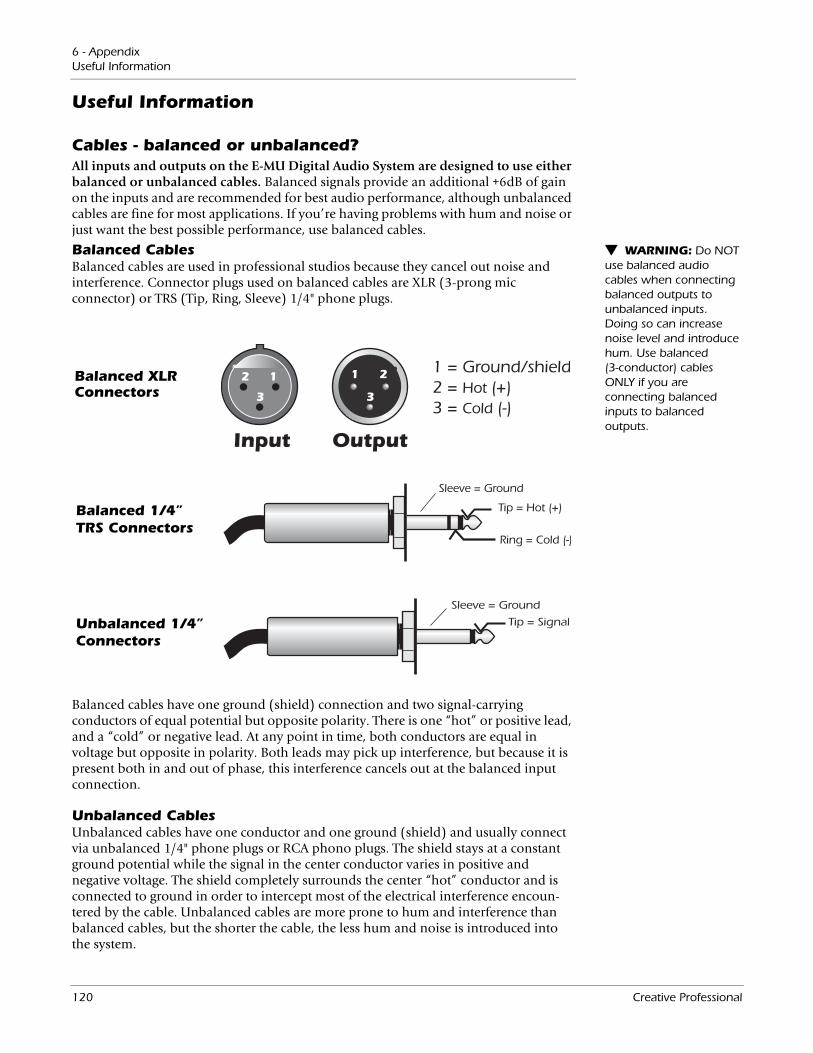
6 - AppendixUseful Information
Useful Information
Cables - balanced or unbalanced?All inputs and outputs on the E-MU Digital Audio System are designed to use either balanced or unbalanced cables. Balanced signals provide an additional +6dB of gain on the inputs and are recommended for best audio performance, although unbalanced cables are fine for most applications. If you’re having problems with hum and noise or just want the best possible performance, use balanced cables.
WARNING: Do NOT use balanced audio cables when connecting balanced outputs to unbalanced inputs. Doing so can increase noise level and introduce hum. Use balanced (3-conductor) cables ONLY if you are connecting balanced inputs to balanced outputs.
Balanced CablesBalanced cables are used in professional studios because they cancel out noise and interference. Connector plugs used on balanced cables are XLR (3-prong mic connector) or TRS (Tip, Ring, Sleeve) 1/4" phone plugs.
Balanced 1/4” TRS Connectors
Balanced XLR Connectors
Unbalanced 1/4” Connectors
Balanced cables have one ground (shield) connection and two signal-carrying conductors of equal potential but opposite polarity. There is one “hot” or positive lead, and a “cold” or negative lead. At any point in time, both conductors are equal in voltage but opposite in polarity. Both leads may pick up interference, but because it is present both in and out of phase, this interference cancels out at the balanced input connection.
Unbalanced CablesUnbalanced cables have one conductor and one ground (shield) and usually connect via unbalanced 1/4" phone plugs or RCA phono plugs. The shield stays at a constant ground potential while the signal in the center conductor varies in positive and negative voltage. The shield completely surrounds the center “hot” conductor and is connected to ground in order to intercept most of the electrical interference encoun-tered by the cable. Unbalanced cables are more prone to hum and interference than balanced cables, but the shorter the cable, the less hum and noise is introduced into the system.
120 Creative Professional
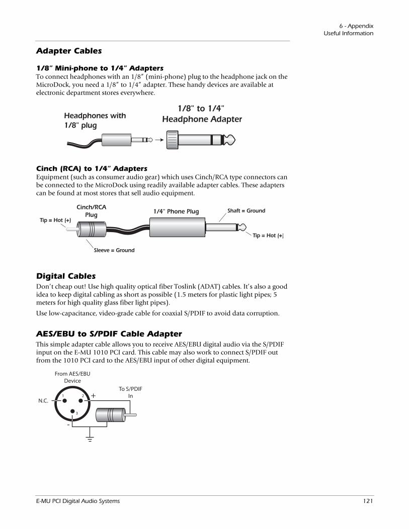
6 - AppendixUseful Information
Adapter Cables
1/8” Mini-phone to 1/4” AdaptersTo connect headphones with an 1/8” (mini-phone) plug to the headphone jack on the MicroDock, you need a 1/8” to 1/4” adapter. These handy devices are available at electronic department stores everywhere.
Cinch (RCA) to 1/4” AdaptersEquipment (such as consumer audio gear) which uses Cinch/RCA type connectors can be connected to the MicroDock using readily available adapter cables. These adapters can be found at most stores that sell audio equipment.
Digital CablesDon’t cheap out! Use high quality optical fiber Toslink (ADAT) cables. It’s also a good idea to keep digital cabling as short as possible (1.5 meters for plastic light pipes; 5 meters for high quality glass fiber light pipes).
Use low-capacitance, video-grade cable for coaxial S/PDIF to avoid data corruption.
AES/EBU to S/PDIF Cable Adapter This simple adapter cable allows you to receive AES/EBU digital audio via the S/PDIF input on the E-MU 1010 PCI card. This cable may also work to connect S/PDIF out from the 1010 PCI card to the AES/EBU input of other digital equipment.
E-MU PCI Digital Audio Systems 121

6 - AppendixUseful Information
GroundingIn order to obtain best results and lowest noise levels, make sure that your computer and any external audio devices are grounded to the same reference. This usually means that you should be using grounded AC cables on both systems and make sure that both systems are connected to the same grounded outlet. Failure to observe this common practice can result in a ground loop. 60 cycle hum in the audio signal is almost always caused by a ground loop.
Phantom PowerPhantom power is a dc voltage (+48 volts) which is normally used to power the pream-plifier of a condenser microphone. Some direct boxes also use phantom power.
Pins 2 and 3 of the MicroDock microphone inputs each carry +48 volts dc referenced to pin 1. Pins 2 and 3 also carry the audio signal which “rides” on top of the constant 48 volts DC. Coupling capacitors at the input of the MicroDock block the +48 volt DC component before the signal is converted into digital form. The audio mutes for a second when phantom power is turned on. After turning phantom power off, wait two full minutes before recording to allow the DC bias to drain from the coupling capacitors since the bias could affect the audio headroom.
1(grd)
3
2
+48V
Balanced dynamic microphones are not affected by phantom power. An unbalanced dynamic microphone may not work properly, but will probably not be damaged if phantom power is left on.
Ribbon microphones should NOT be used with phantom power on. Doing so can seriously damage the ribbon element. Since ribbon microphones are fairly specialized and generally
expensive, you’ll know if you own one. Most microphones are either of dynamic or condenser type and these are not harmed by phantom power.
Appearance Settings in WindowsAdjusting the “Performance Options”in Windows will improve the screen appearance when moving the mixer around on the screen.
To Improve the Appearance Settings:1. Open the Windows Control Panel. (Start, Settings, Control Panel).2. Select System. Select the Advanced Settings tab.3. Under Visual Effects, select Adjust for Best Performance. Click OK.
122 Creative Professional
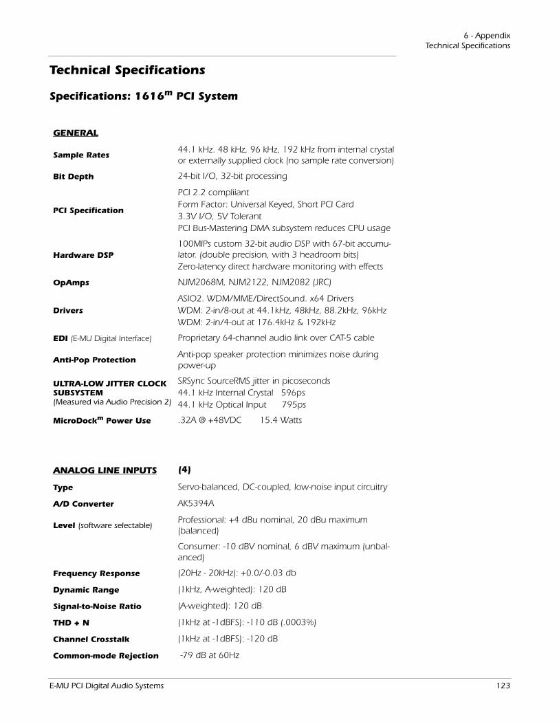
6 - AppendixTechnical Specifications
Technical Specifications
Specifications: 1616m PCI System
GENERAL
Sample Rates44.1 kHz. 48 kHz, 96 kHz, 192 kHz from internal crystal or externally supplied clock (no sample rate conversion)
Bit Depth 24-bit I/O, 32-bit processing
PCI Specification
PCI 2.2 compliiantForm Factor: Universal Keyed, Short PCI Card3.3V I/O, 5V TolerantPCI Bus-Mastering DMA subsystem reduces CPU usage
Hardware DSP100MIPs custom 32-bit audio DSP with 67-bit accumu-lator. (double precision, with 3 headroom bits)Zero-latency direct hardware monitoring with effects
OpAmps NJM2068M, NJM2122, NJM2082 (JRC)
DriversASIO2. WDM/MME/DirectSound. x64 DriversWDM: 2-in/8-out at 44.1kHz, 48kHz, 88.2kHz, 96kHzWDM: 2-in/4-out at 176.4kHz & 192kHz
EDI (E-MU Digital Interface) Proprietary 64-channel audio link over CAT-5 cable
Anti-Pop ProtectionAnti-pop speaker protection minimizes noise during power-up
ULTRA-LOW JITTER CLOCK SUBSYSTEM (Measured via Audio Precision 2)
SRSync SourceRMS jitter in picoseconds 44.1 kHz Internal Crystal 596ps 44.1 kHz Optical Input 795ps
MicroDockm Power Use .32A @ +48VDC 15.4 Watts
ANALOG LINE INPUTS (4)
Type Servo-balanced, DC-coupled, low-noise input circuitry
A/D Converter AK5394A
Level (software selectable)Professional: +4 dBu nominal, 20 dBu maximum (balanced)
Consumer: -10 dBV nominal, 6 dBV maximum (unbal-anced)
Frequency Response (20Hz - 20kHz): +0.0/-0.03 db
Dynamic Range (1kHz, A-weighted): 120 dB
Signal-to-Noise Ratio (A-weighted): 120 dB
THD + N (1kHz at -1dBFS): -110 dB (.0003%)
Channel Crosstalk (1kHz at -1dBFS): -120 dB
Common-mode Rejection -79 dB at 60Hz
E-MU PCI Digital Audio Systems 123
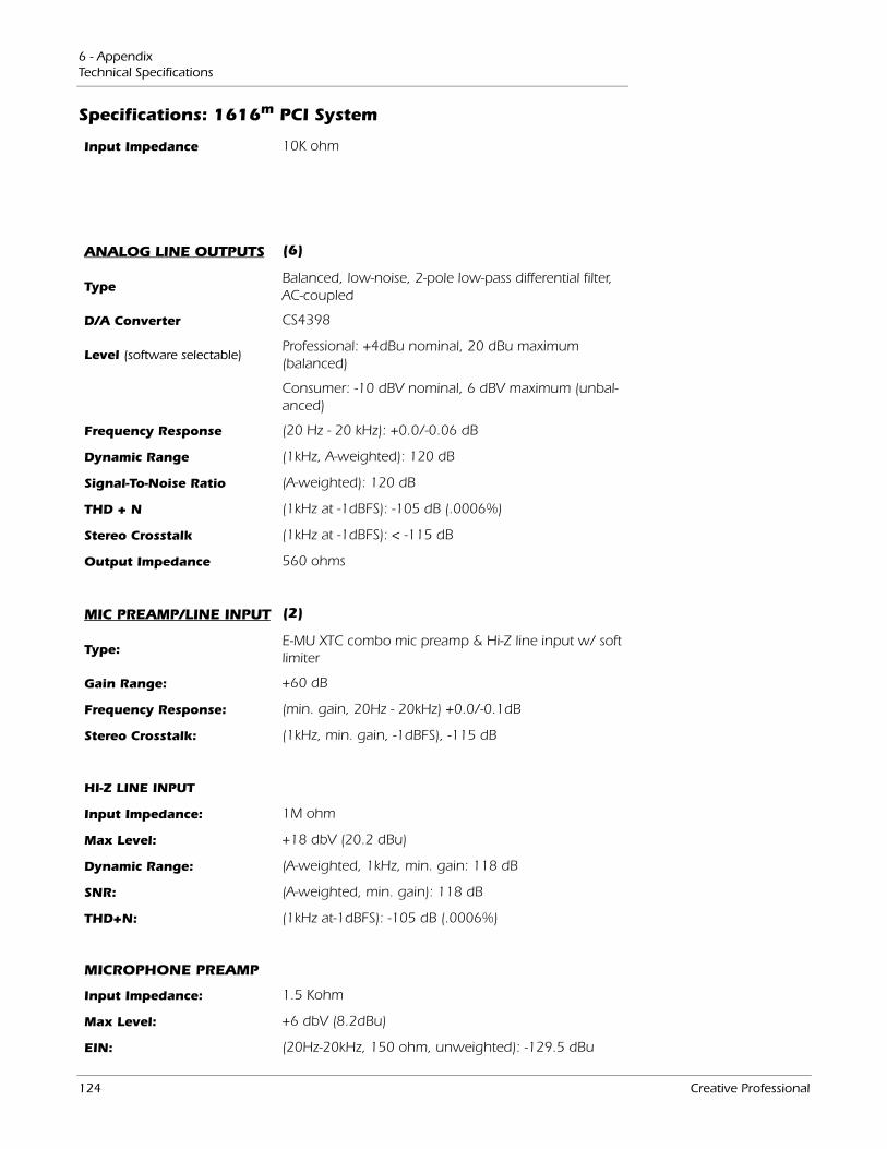
6 - AppendixTechnical Specifications
Input Impedance 10K ohm
ANALOG LINE OUTPUTS (6)
TypeBalanced, low-noise, 2-pole low-pass differential filter, AC-coupled
D/A Converter CS4398
Level (software selectable)Professional: +4dBu nominal, 20 dBu maximum (balanced)
Consumer: -10 dBV nominal, 6 dBV maximum (unbal-anced)
Frequency Response (20 Hz - 20 kHz): +0.0/-0.06 dB
Dynamic Range (1kHz, A-weighted): 120 dB
Signal-To-Noise Ratio (A-weighted): 120 dB
THD + N (1kHz at -1dBFS): -105 dB (.0006%)
Stereo Crosstalk (1kHz at -1dBFS): < -115 dB
Output Impedance 560 ohms
MIC PREAMP/LINE INPUT (2)
Type:E-MU XTC combo mic preamp & Hi-Z line input w/ soft limiter
Gain Range: +60 dB
Frequency Response: (min. gain, 20Hz - 20kHz) +0.0/-0.1dB
Stereo Crosstalk: (1kHz, min. gain, -1dBFS), -115 dB
HI-Z LINE INPUT
Input Impedance: 1M ohm
Max Level: +18 dbV (20.2 dBu)
Dynamic Range: (A-weighted, 1kHz, min. gain: 118 dB
SNR: (A-weighted, min. gain): 118 dB
THD+N: (1kHz at-1dBFS): -105 dB (.0006%)
MICROPHONE PREAMP
Input Impedance: 1.5 Kohm
Max Level: +6 dbV (8.2dBu)
EIN: (20Hz-20kHz, 150 ohm, unweighted): -129.5 dBu
Specifications: 1616m PCI System
124 Creative Professional
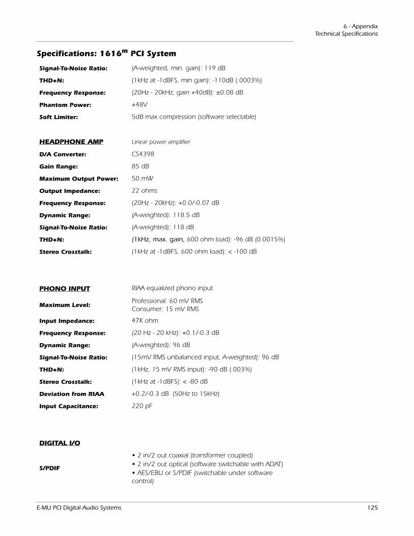
6 - AppendixTechnical Specifications
Signal-To-Noise Ratio: (A-weighted, min. gain): 119 dB
THD+N: (1kHz at -1dBFS, min gain): -110dB (.0003%)
Frequency Response: (20Hz - 20kHz, gain +40dB): ±0.08 dB
Phantom Power: +48V
Soft Limiter: 5dB max compression (software selectable)
HEADPHONE AMP Linear power amplifier
D/A Converter: CS4398
Gain Range: 85 dB
Maximum Output Power: 50 mW
Output Impedance: 22 ohms
Frequency Response: (20Hz - 20kHz): +0.0/-0.07 dB
Dynamic Range: (A-weighted): 118.5 dB
Signal-To-Noise Ratio: (A-weighted): 118 dB
THD+N: (1kHz, max. gain, 600 ohm load): -96 dB (0.0015%)
Stereo Crosstalk: (1kHz at -1dBFS, 600 ohm load): < -100 dB
PHONO INPUT RIAA equalized phono input
Maximum Level:Professional: 60 mV RMSConsumer: 15 mV RMS
Input Impedance: 47K ohm
Frequency Response: (20 Hz - 20 kHz): +0.1/-0.3 dB
Dynamic Range: (A-weighted): 96 dB
Signal-To-Noise Ratio: (15mV RMS unbalanced input, A-weighted): 96 dB
THD+N: (1kHz, 15 mV RMS input): -90 dB (.003%)
Stereo Crosstalk: (1kHz at -1dBFS): < -80 dB
Deviation from RIAA +0.2/-0.3 dB (50Hz to 15kHz)
Input Capacitance: 220 pF
DIGITAL I/O
S/PDIF
• 2 in/2 out coaxial (transformer coupled)• 2 in/2 out optical (software switchable with ADAT)• AES/EBU or S/PDIF (switchable under software control)
Specifications: 1616m PCI System
E-MU PCI Digital Audio Systems 125
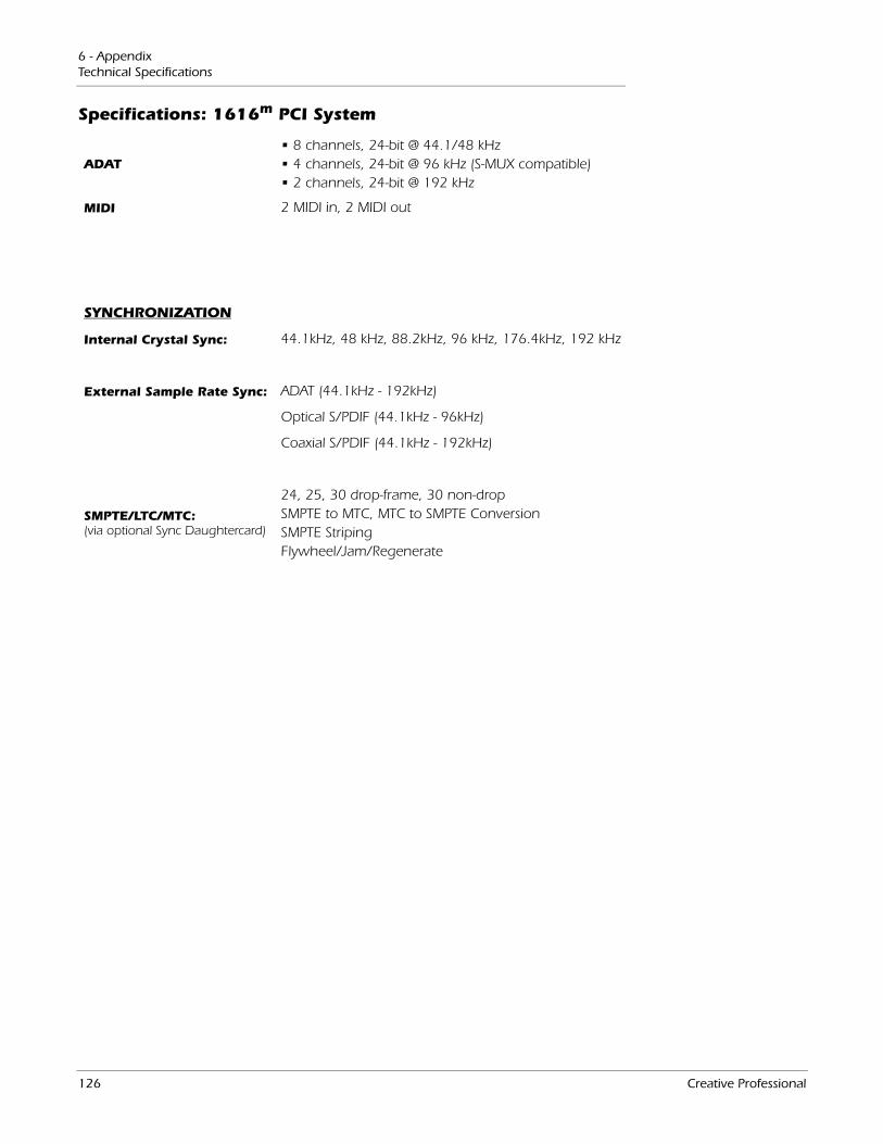
6 - AppendixTechnical Specifications
ADAT• 8 channels, 24-bit @ 44.1/48 kHz• 4 channels, 24-bit @ 96 kHz (S-MUX compatible)• 2 channels, 24-bit @ 192 kHz
MIDI 2 MIDI in, 2 MIDI out
SYNCHRONIZATION
Internal Crystal Sync: 44.1kHz, 48 kHz, 88.2kHz, 96 kHz, 176.4kHz, 192 kHz
External Sample Rate Sync: ADAT (44.1kHz - 192kHz)
Optical S/PDIF (44.1kHz - 96kHz)
Coaxial S/PDIF (44.1kHz - 192kHz)
SMPTE/LTC/MTC:(via optional Sync Daughtercard)
24, 25, 30 drop-frame, 30 non-dropSMPTE to MTC, MTC to SMPTE ConversionSMPTE StripingFlywheel/Jam/Regenerate
Specifications: 1616m PCI System
126 Creative Professional

6 - AppendixTechnical Specifications
Specifications: 1616 PCI System
GENERAL
Sample Rates:44.1 kHz. 48 kHz, 88.2kHz, 96 kHz, 176.4kHz & 192 kHz from internal crystal or externally supplied clock (no sample rate conversion)
Bit Depths: 16 or 24-bit I/O, 32-bit processing
PCI Specification
PCI 2.2 compliiantForm Factor: Universal Keyed, Short PCI Card3.3V I/O, 5V TolerantPCI Bus-Mastering DMA subsystem reduces CPU usage
Hardware DSP:100MIPs custom 32-bit audio DSP with 67-bit accumu-lator. (double precision, with 3 headroom bits)Zero-latency direct hardware monitoring with effects
OpAmps: NJM2068M, NJM2122, NJM2082 (JRC)
Drivers:ASIO2. WDM/MME/DirectSound. x64 DriversWDM: 2-in/8-out at 44.1kHz, 48kHz, 88.2kHz, 96kHzWDM: 2-in/4-out at 176.4kHz & 192kHz
EDI: (E-MU Digital Interface) Proprietary 64-channel audio link over CAT-5 cable
Anti-Pop Protection:Anti-pop speaker protection minimizes noise during power-up
Ultra Low Jitter Clock Subsystem: (Measured via Audio Precision 2)
SRSync SourceRMS jitter in picoseconds 44.1 kHz Internal Crystal 596ps 44.1 kHz Optical Input 795ps
MicroDock Power Use .20A @ +48VDC 10 Watts
ANALOG LINE INPUTS (4)
Type: Servo-balanced, DC-coupled, low-noise input circuitry
A/D Converter: PCM1804
Level (software selectable)Professional: +4 dBu nominal, 20 dBu maximum (balanced)
Consumer: -10 dBV nominal, 6 dBV maximum (unbal-anced)
Frequency Response (20Hz - 20kHz): +0.0/-0.03 db
Dynamic Range (1kHz, A-weighted): 112 dB
Signal-to-Noise Ratio (A-weighted): 112 dB
THD + N (1kHz at -1dBFS): -102.5 dB (.0012%)
Channel Crosstalk (1kHz at -1dBFS): -115 dB,
Input Impedance 10K ohm
E-MU PCI Digital Audio Systems 127
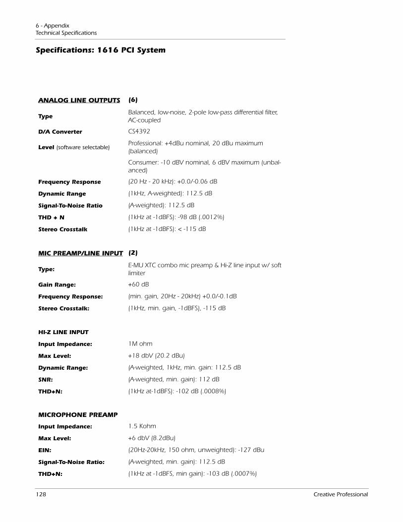
6 - AppendixTechnical Specifications
ANALOG LINE OUTPUTS (6)
TypeBalanced, low-noise, 2-pole low-pass differential filter, AC-coupled
D/A Converter CS4392
Level (software selectable)Professional: +4dBu nominal, 20 dBu maximum (balanced)
Consumer: -10 dBV nominal, 6 dBV maximum (unbal-anced)
Frequency Response (20 Hz - 20 kHz): +0.0/-0.06 dB
Dynamic Range (1kHz, A-weighted): 112.5 dB
Signal-To-Noise Ratio (A-weighted): 112.5 dB
THD + N (1kHz at -1dBFS): -98 dB (.0012%)
Stereo Crosstalk (1kHz at -1dBFS): < -115 dB
MIC PREAMP/LINE INPUT (2)
Type:E-MU XTC combo mic preamp & Hi-Z line input w/ soft limiter
Gain Range: +60 dB
Frequency Response: (min. gain, 20Hz - 20kHz) +0.0/-0.1dB
Stereo Crosstalk: (1kHz, min. gain, -1dBFS), -115 dB
HI-Z LINE INPUT
Input Impedance: 1M ohm
Max Level: +18 dbV (20.2 dBu)
Dynamic Range: (A-weighted, 1kHz, min. gain: 112.5 dB
SNR: (A-weighted, min. gain): 112 dB
THD+N: (1kHz at-1dBFS): -102 dB (.0008%)
MICROPHONE PREAMP
Input Impedance: 1.5 Kohm
Max Level: +6 dbV (8.2dBu)
EIN: (20Hz-20kHz, 150 ohm, unweighted): -127 dBu
Signal-To-Noise Ratio: (A-weighted, min. gain): 112.5 dB
THD+N: (1kHz at -1dBFS, min gain): -103 dB (.0007%)
Specifications: 1616 PCI System
128 Creative Professional
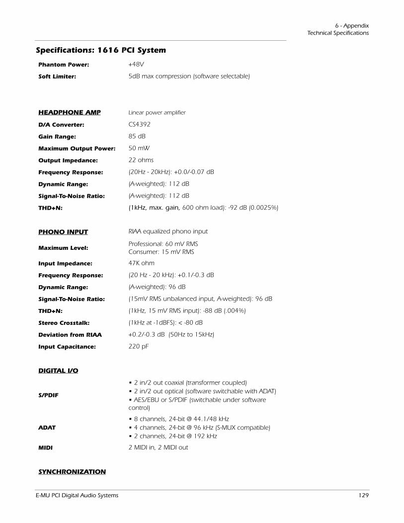
6 - AppendixTechnical Specifications
Phantom Power: +48V
Soft Limiter: 5dB max compression (software selectable)
HEADPHONE AMP Linear power amplifier
D/A Converter: CS4392
Gain Range: 85 dB
Maximum Output Power: 50 mW
Output Impedance: 22 ohms
Frequency Response: (20Hz - 20kHz): +0.0/-0.07 dB
Dynamic Range: (A-weighted): 112 dB
Signal-To-Noise Ratio: (A-weighted): 112 dB
THD+N: (1kHz, max. gain, 600 ohm load): -92 dB (0.0025%)
PHONO INPUT RIAA equalized phono input
Maximum Level:Professional: 60 mV RMSConsumer: 15 mV RMS
Input Impedance: 47K ohm
Frequency Response: (20 Hz - 20 kHz): +0.1/-0.3 dB
Dynamic Range: (A-weighted): 96 dB
Signal-To-Noise Ratio: (15mV RMS unbalanced input, A-weighted): 96 dB
THD+N: (1kHz, 15 mV RMS input): -88 dB (.004%)
Stereo Crosstalk: (1kHz at -1dBFS): < -80 dB
Deviation from RIAA +0.2/-0.3 dB (50Hz to 15kHz)
Input Capacitance: 220 pF
DIGITAL I/O
S/PDIF
• 2 in/2 out coaxial (transformer coupled)• 2 in/2 out optical (software switchable with ADAT)• AES/EBU or S/PDIF (switchable under software control)
ADAT• 8 channels, 24-bit @ 44.1/48 kHz• 4 channels, 24-bit @ 96 kHz (S-MUX compatible)• 2 channels, 24-bit @ 192 kHz
MIDI 2 MIDI in, 2 MIDI out
SYNCHRONIZATION
Specifications: 1616 PCI System
E-MU PCI Digital Audio Systems 129
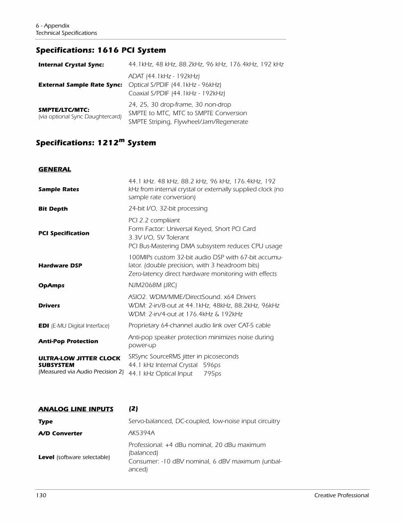
6 - AppendixTechnical Specifications
Internal Crystal Sync: 44.1kHz, 48 kHz, 88.2kHz, 96 kHz, 176.4kHz, 192 kHz
External Sample Rate Sync:ADAT (44.1kHz - 192kHz)Optical S/PDIF (44.1kHz - 96kHz)Coaxial S/PDIF (44.1kHz - 192kHz)
SMPTE/LTC/MTC:(via optional Sync Daughtercard)
24, 25, 30 drop-frame, 30 non-dropSMPTE to MTC, MTC to SMPTE ConversionSMPTE Striping, Flywheel/Jam/Regenerate
Specifications: 1212m System
GENERAL
Sample Rates44.1 kHz. 48 kHz, 88.2 kHz, 96 kHz, 176.4kHz, 192 kHz from internal crystal or externally supplied clock (no sample rate conversion)
Bit Depth 24-bit I/O, 32-bit processing
PCI Specification
PCI 2.2 compliiantForm Factor: Universal Keyed, Short PCI Card3.3V I/O, 5V TolerantPCI Bus-Mastering DMA subsystem reduces CPU usage
Hardware DSP100MIPs custom 32-bit audio DSP with 67-bit accumu-lator. (double precision, with 3 headroom bits)Zero-latency direct hardware monitoring with effects
OpAmps NJM2068M (JRC)
DriversASIO2. WDM/MME/DirectSound. x64 DriversWDM: 2-in/8-out at 44.1kHz, 48kHz, 88.2kHz, 96kHzWDM: 2-in/4-out at 176.4kHz & 192kHz
EDI (E-MU Digital Interface) Proprietary 64-channel audio link over CAT-5 cable
Anti-Pop ProtectionAnti-pop speaker protection minimizes noise during power-up
ULTRA-LOW JITTER CLOCK SUBSYSTEM (Measured via Audio Precision 2)
SRSync SourceRMS jitter in picoseconds 44.1 kHz Internal Crystal 596ps 44.1 kHz Optical Input 795ps
ANALOG LINE INPUTS (2)
Type Servo-balanced, DC-coupled, low-noise input circuitry
A/D Converter AK5394A
Level (software selectable)
Professional: +4 dBu nominal, 20 dBu maximum (balanced)Consumer: -10 dBV nominal, 6 dBV maximum (unbal-anced)
Specifications: 1616 PCI System
130 Creative Professional
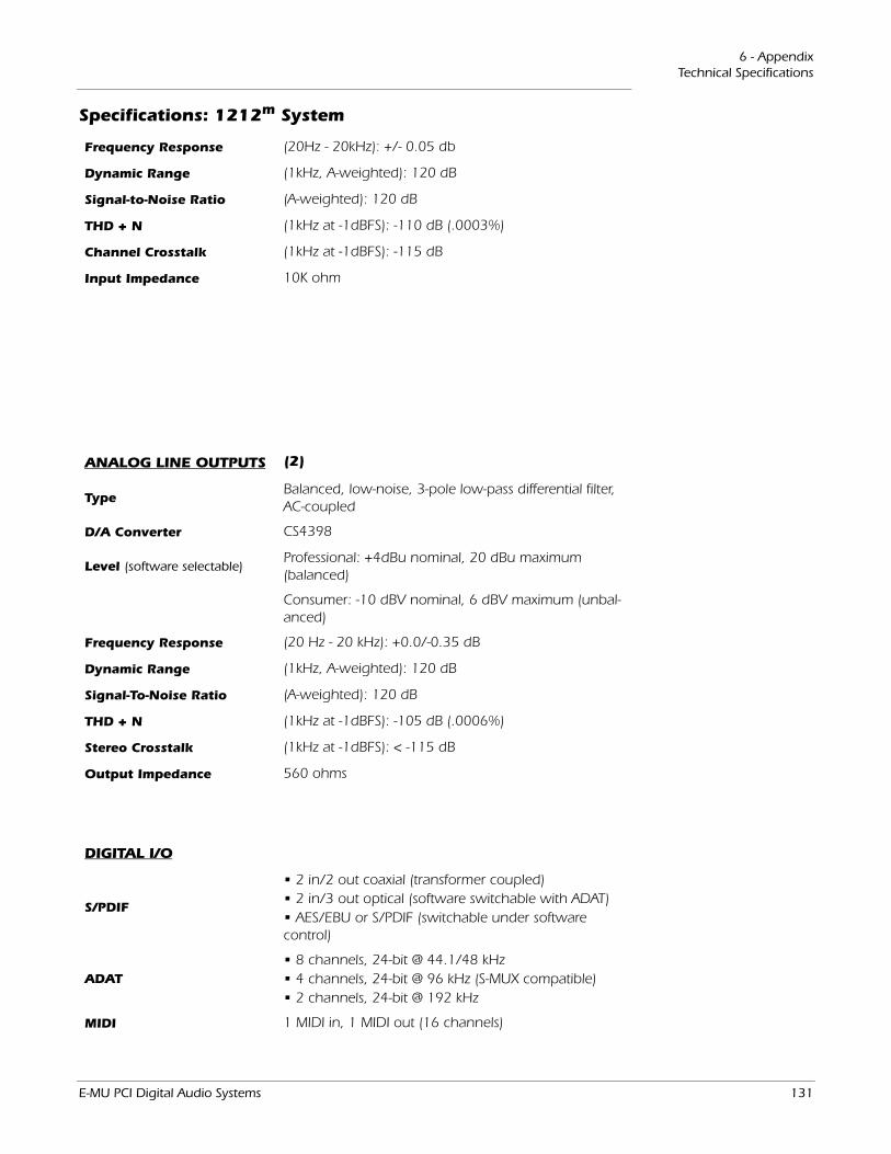
6 - AppendixTechnical Specifications
Frequency Response (20Hz - 20kHz): +/- 0.05 db
Dynamic Range (1kHz, A-weighted): 120 dB
Signal-to-Noise Ratio (A-weighted): 120 dB
THD + N (1kHz at -1dBFS): -110 dB (.0003%)
Channel Crosstalk (1kHz at -1dBFS): -115 dB
Input Impedance 10K ohm
ANALOG LINE OUTPUTS (2)
TypeBalanced, low-noise, 3-pole low-pass differential filter, AC-coupled
D/A Converter CS4398
Level (software selectable)Professional: +4dBu nominal, 20 dBu maximum (balanced)
Consumer: -10 dBV nominal, 6 dBV maximum (unbal-anced)
Frequency Response (20 Hz - 20 kHz): +0.0/-0.35 dB
Dynamic Range (1kHz, A-weighted): 120 dB
Signal-To-Noise Ratio (A-weighted): 120 dB
THD + N (1kHz at -1dBFS): -105 dB (.0006%)
Stereo Crosstalk (1kHz at -1dBFS): < -115 dB
Output Impedance 560 ohms
DIGITAL I/O
S/PDIF
• 2 in/2 out coaxial (transformer coupled)• 2 in/3 out optical (software switchable with ADAT)• AES/EBU or S/PDIF (switchable under software control)
ADAT• 8 channels, 24-bit @ 44.1/48 kHz• 4 channels, 24-bit @ 96 kHz (S-MUX compatible)• 2 channels, 24-bit @ 192 kHz
MIDI 1 MIDI in, 1 MIDI out (16 channels)
Specifications: 1212m System
E-MU PCI Digital Audio Systems 131
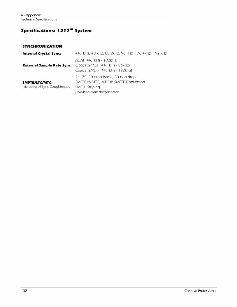
6 - AppendixTechnical Specifications
SYNCHRONIZATION
Internal Crystal Sync: 44.1kHz, 48 kHz, 88.2kHz, 96 kHz, 176.4kHz, 192 kHz
External Sample Rate Sync:ADAT (44.1kHz - 192kHz)Optical S/PDIF (44.1kHz - 96kHz)Coaxial S/PDIF (44.1kHz - 192kHz)
SMPTE/LTC/MTC:(via optional Sync Daughtercard)
24, 25, 30 drop-frame, 30 non-dropSMPTE to MTC, MTC to SMPTE ConversionSMPTE StripingFlywheel/Jam/Regenerate
Specifications: 1212m System
132 Creative Professional
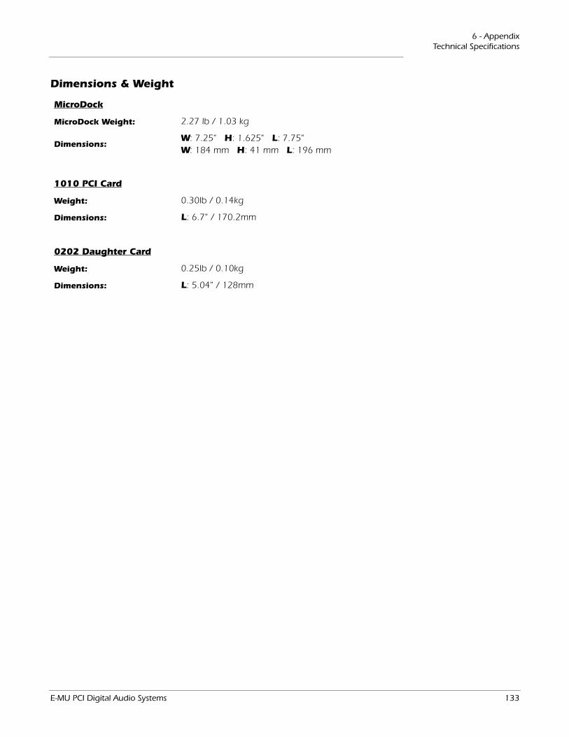
6 - AppendixTechnical Specifications
Dimensions & Weight
MicroDock
MicroDock Weight: 2.27 lb / 1.03 kg
Dimensions:W: 7.25" H: 1.625" L: 7.75" W: 184 mm H: 41 mm L: 196 mm
1010 PCI Card
Weight: 0.30lb / 0.14kg
Dimensions: L: 6.7" / 170.2mm
0202 Daughter Card
Weight: 0.25lb / 0.10kg
Dimensions: L: 5.04" / 128mm
E-MU PCI Digital Audio Systems 133
6 - AppendixInternet References
Internet ReferencesThe internet contains vast resources for the computer musician. A few useful sites are listed here, but there are plenty more. Check it out.
Software Updates, Tips & Tutorials............... http://www.emu.com
Setting up a PC for Digital Audio .................. http://www.musicxp.net
MIDI Basics ....................................................... Search for “MIDI Basics” (many sites)
MIDI & Audio Recording ................................ http://www.midiworld.com
MIDI & Audio Recording ................................ http://www.synthzone.com
ASIO, Cubase & Digital Audio ....................... http://www.steinberg.net
ASIO, Cubase & Digital Audio ....................... http://www.steinbergusers.com/cubasele/le_support.php
Cubase Users Group ........................................ http://www.groups.yahoo.com/group/cubase/messages
ForumsUnofficial E-MU Forum ........................... http://www.productionforums.com/emu/
KVR Forum ............................................. http://www.kvr-vst.com/forum/
Driver Heaven Forum............................. http://www.driverheaven.net/search.php?s
MIDI Addict Forum ................................ http://forum.midiaddict.com/search.php
Home Recording Forum ........................ http://homerecording.com/bbs/search.php?s=d866b60193933eb726660e7bd90dfb27
Sound-On-Sound Forum ....................... http://sound-on-sound.com/forum/
Studio-Central Cafe Forum.................... http://studio-central.com/phpbb/search.php
Sound Card Benchmarking.................... http://audio.rightmark.org
134 Creative Professional
6 - AppendixInternet References
Declaration of Conformity
Trade Name: E-MU Systems
Model No.: EM8850 EM8870 EM8871
Responsible Party: E-MU Systems
Address: 1500 Green Hills Road, Scotts Valley, CA 95066 U.S.A.
This device complies with Part 15 of the FCC rules. Operation is subject to the following two conditions: (1) This device may not cause harmful interference, and (2) this device must accept any interference received, including interference that may cause undesired operation.
CAUTIONYou are cautioned that any changes or modifications not expressly approved in this manual could void your authority to operate this equipment.
Note:This equipment has been tested and found to comply with the limits for a Class B digital device, pursuant to Part 15 of the FCC Rules. These limits are designed to provide reasonable protection against harmful interference in a residential installation. This equipment generates, uses, and can radiate radio frequency energy and, if not installed and used in accordance with the instructions, may cause harmful interference to radio communications. However, there is no guarantee that interference to radio or television reception, which can be determined by turning the equipment off and on, the user is encouraged to try to correct the interference by one or more of the following measures:
• Reorient or relocate the receiving antenna.
• Increase the separation between the equipment and receiver.
• Connect the equipment into an outlet on a circuit different from that to which the receiver is connected.
• Consult the dealer or an experienced radio/TV technician for help.
The supplied interface cables must be used with the equipment in order to comply with the limits for a digital device pursuant to Subpart B of Part 15 of FCC Rules.
E-MU PCI Digital Audio Systems 135
6 - AppendixInternet References
Compliance Information
United States Compliance Information
FCC Part 15 Subpart B Class B using:
CISPR 22 (1997) Class B
ANSI C63.4 (1992) method
FCC Site No.90479
Canada Compliance Information
ICES-0003 Class B using:
CISPR 22 (1997) Class B
ANSI C63.4 (1992) method
Industry of Canada File No.IC 3171-B
European Union Compliance Information
EN55024 (1998)
EN55022 (1998) Class B
EN61000-3-2 (2001)
EN61000-3-3 (1995 w/A1:98)
Australia/New Zealand Compliance Information
AS/NZS 3548(1995 w/A1 & A2:97) Class B
EN55022 (1998) Class B
Japan Compliance Information
VCCI (April 2000) Class B using:
CISPR 22(1997) Class B
VCCI Acceptance Nos. R-1233 & C-1297
Attention for the Customers in EuropeThis product has been tested and found compliant with the limits set out in the EMC Directive for using connection cables shorter than 3 meters (9.8 feet).
NoticeIf static electricity or electromagnetism causes data transfer to discontinue midway (fail), restart the application or disconnect and connect the Firewire cable again.
136 Creative Professional
IndexNumerics
Index
Numerics0202 Daughter Card 201010 PCI Card 191-Band Para EQ 631-Band Shelf EQ 631-Time Jam Sync, SMPTE 1153-Band EQ 6448 Volt DC Adapter 1748 Volt Phantom Power 22, 1224-Band EQ 655.1 Surround Connections 275.1/7.1 Surround 3888kHz/96kHz Sample Rate 111
AA/D Converter
1212M 1301616 1271616M 123
AC3 Passthrough 23ADAT Optical
at 96kHz & 192kHz 111connection example 119input/output connector 19, 23
ADSR, reshaper effect 84Advanced Parameters, RFX compressor 92AES/EBU to S/PDIF Adapter 121Ambience Reduction, using reshaper effect 83Analog I/O
0202 Daughter Card 20MicroDock 25
Anti-Pop Protection 123, 127, 130Appearance, improving 122ASIO
direct monitor 41send 39
Attackbasic compressor 68curve, reshaper 85threshold, reshaper 84
Auto Makeup, RFX compressor 92
Auto Volume Pedal, using reshaper effect 83Automating PowerFX 103Auto-Release, RFX compressor 95Auto-Wah 66Aux Bus 47Auxiliary Effects Assignment 53Auxiliary Returns 53Auxiliary Sends 47
used as extra mix busses 53
BBackground program, disabling 31Backward Cymbal Effect 99Balance Control, monitor 54Balanced Cables 25, 120Band Cut Filter 89Band Pass Filter 89Bit Depth 123Block Diagram, mixer 30Bypass
effect insert 59insert 46send/return insert 51
CCategory
create new preset 57delete effects 57rename effects 57
CDs, playing 37Chorus 67
using freq. shifter 71Clicks & Pops, in the audio 19, 23, 117Clipping Indicators 22Clock, external 34Comb Filter 70Compressor
basic 67RFX 90
Connecting, MicroDock 16Connection Diagrams 24, 26Connections
5.1 surround 27ADAT optical 23EDI cable 17front panel 22rear panel 25S/PDIF 22
Connectors, interface 14Core Effects
descriptions 63listing 62
Core FX Presets, importing/exporting 58Cross-over, creating with multimode filter 86
E-MU PCI Digital Audio Systems 137
IndexD
DD/A Converter
1212M 1311616 1281616M 124
Damping, high frequency 73, 78Decay Time, lite reverb 73Decay Time, reverb 78De-esser, creating 100Delete
folder 57FX user preset 61mixer strip 38
Diffusion 78Digital Cables 120Digital I/O Specs 125Digital Interface, S/PDIF 19, 22Direct Sound Source 37Distortion 69Doppler, effect using Rotary 75Drivers 123, 127, 130Drivers, installing 18Drum Punch 98Ducker 97DVD, playing in 5.1/7.1 surround 38Dynamic Range 124, 128, 131
EEcho, creating 74E-Delay Compensator 107Edge, distortion 69EDI 123, 127, 130EDI Cable 17EDI Connector 19, 26Effects
1-band para EQ 631-band shelf EQ 633-band EQ 644-band EQ 65auto wah 66chorus 67compressor 67create new folder 57creating robot voice 74descriptions 63display screen 51distortion 69edit 56flanger 70frequency shifter 71gate 80leveling amp 72lite reverb 73mono delays 74multimode eq 86
overview 55palette 55phase shifter 75placing into an insert location 39preset
create new 60delete 61overwrite 61rename 61
recording 57reshaper 83RFX compressor 90rotary 75selecting 56stereo delays 77stereo reverb 78using in VST host application 101vocal morpher 79
Effects, order of 57E-MU 0202 Daughter Card, description 20E-MU 1010 PCI Card
description 19installing 15
E-MU Icon, in taskbar 31Envelope, reverberation 73, 78E-Wire 106Exit PatchMix DSP Services 31Exporting Core FX & FX Insert Chains 58External Clock 34, 117, 119External Mode, SMPTE 115External Sync Source 34Extra Buffers 102
FFactory Templates 33Flanger 70Flywheel Mode, SMPTE 115Frequency Shifter 71Front Panel Connections, MicroDock 22Full-Frame Messages 117FX Edit Screen 59FX Insert Chains 56
importing/exporting 58
GGain Reduction Meter, gate effect 82Gain, compressor 68Gate
effect 80RFX compressor 94
Ground Loop, preventing 122Ground Lug, turntable 25Grounding 122
138 Creative Professional
IndexH
HHardware DSP 123, 130Headphone Amp Specs 125, 129Headphone Output 23Headphones, using with the 0202 20Help System 31High Frequency Damping, stereo reverb 78High Frequency Decay Factor, lite reverb 73High Frequency Rolloff
mono delays 74stereo delays 77
Highpass Filter 87Hold Time, reshaper effect 84Host Input Display 52Host Mode, SMPTE 115Host Output Display 52Hum, in the audio 122
IImporting Core FX & FX Insert Chains 58Increase Drum Punch 98Input
display 52level
line 25setting 43specs 123, 127, 130
typemixer strip 36red color 36
Insertadd effect 39add send 40add send/return 40, 41bypass 46, 59delete 46menu 40meter 43mixer strip 39solo 46, 59types 39
InstallingE-MU 0202 daughter card 16E-MU 1010 PCI card 15sync daughter card 16
InterfaceADAT 20, 23EDI 26MIDI 20, 26required cable 17S/PDIF 19, 22SMPTE 114word clock 117
Invert, polarity 44
JJitter Spec
1616 system 1301616M system 123
LLabel, scribble strip 49Latency, monitoring without 41LED indicators 22Level Fader 49Level Meter, gate effect 82Leveling Amp 72Levels, setting input 43LFO
flanger 70phase shifter 75vocal morpher 79
Limiter 68Limiting Peaks 98Line Level I/O
0202 daughter card 20MicroDock 25
Lite Reverb 73Lookahead
gate effect 81reshaper effect 85RFX compressor 94
Low Frequency Damping 78Low Frequency Decay Factor, lite reverb 73Lowpass Filter 87
MMain
bus 50inserts 54output fader 54section 50
Masterreturn level 50send level 50volume control 54
Max Compression, RFX compressor 96Max Gain Reduction, gate effect 81Meter
insert 42main output 54setting input levels using 43
MicroDockconnecting 17inputs/outputs 21power switch 17
MicroDock Power Use 127MicroDockM Power Usage 123Microphone Preamps 22
E-MU PCI Digital Audio Systems 139

IndexN
MIDIbreakout cable 26I/O jacks
0202 Daughter Card 20MicroDock 26
jacks 22time code 117
MIDI 2, not working 21Mini-Phone Outputs 26Mixer
block diagram 30overview 29strip 36
aux send 47fader 49insert 39label 49mute button 49new 37solo button 49type 37
viewing 29Mixer Strip
add new 37delete 38type 37
Monitorbalance control 54mix 50mute 50output 25
level control 54mute 54
Mono Delays 74MTC 117
enabling 117to SMPTE Conversion 114
Multimode Filter 86Mute
mixer strip 49monitor 50
NNeg Compression, RFX compressor 96New
mixer strip 37preset category 57session 31, 32
at 176k/192k 111user effect preset 60
Noise Gate 80Notes, Tips & Warnings 12
OOpAmps 123Optical Cables 121Optical S/PDIF 23, 35Order of Effects 57Output
fader, main 54level
line 25meters 54monitor 54SMPTE 115
routing display 52section 54
PPalette, effects 55Pan 49Pan Controls 36Parametric EQ, setting up 64PatchMix DSP, disabling 31PCI Specification 123, 127, 130Peak Limiter 91Peak Meters 42Phantom Power 22
description 122Phase Invert 44Phase Shifter 75Phoneme 79Phono Input Specs 125, 129Physical Input/Output Display 52Pink Noise Generator 45Playing CDs 37Post Gain, leveling amp 72Power Switch, MicroDock 17PowerFX 101
resource availability 103Preamp
microphone 22turntable 25
Pre-Delay, compressor 68Pre-Fader Aux Sends 50Preset
create new 60delete 61overwrite effects 61rename effects 61select user 60
Punch Enhancementreshaper effect 83using gate effect 80
Punch Reducer, using reshaper effect 83
140 Creative Professional
IndexQ
QQuarter-Frame Messages 117
RRatio
compressor 68RFX compressor 91
Recording Effects or Recording Dry 57Red Strip 36Reducing Noise 122Release Curve, reshaper effect 85Release Time, gate effect 81Release, compressor 68Render Mode 102Reshaper 83Reverb, envelope 73, 78Reverberation 78RFX Compressor 90RJ45 Connector 16Robot Voice Effects, creating 77Rotary, effect 75Rubber Feet, installing on Audio Dock 18Rumble Filter, using multimode filter 86
SS/MUX 111S/PDIF
cables 121inputs and outputs 19, 22optical 23
S/PDIF to AES/EBU Adapter 121Sample Rates 123
setting 32Save
effect user preset 60, 61FX Insert Chains 56session 33
Scribble Strip 49Send
/return insert 40, 41bypass or solo 51
auxiliary 47insert 40
Send/Return Levels 50Session 32
creating 176k/192k 33, 111creating new 32templates 33
at 176k/192k 33, 111Setting Up the E-MU Digital Audio System 13Settings
I/O 34input level 22system 33
Sibilance, reducing 100Sidechain
creating a de-esser 100creating a ducker 97effects routing 47, 53
Signal Generator Insert 45Signal Level Indicators
LEDs 22meters 54
Signal Level, increasing 20, 25Sine Wave Oscillator 45Smooth Bass Guitar Level 98SMPTE 114
example connection 116Soft Knee, RFX compressor 92Soft Limiters 44Software Installation 18Solo
button 49insert 46, 59, 60send/return insert 51
Specifications1212M System 1301616 System 1271616M System 123
Start Time, SMPTE 115Stereo Delays 77Stereo Reverb 78Strip
add new 37input type 36mixer 36
Striping SMPTE 116Submixing 47Subwoofer Filter, using multimode filter 86Surround Sound
channel chart 27, 38connections 27playback 38
Sync/Sample Rate Indicators 53Synchronization
ADAT example 119source 34
System Settings 33
TT-Connector, word clock 118Templates, session 33Termination, word clock 118Test Tone Insert 45Threshold
basic compressor 68gate effect 81RFX compressor 91
E-MU PCI Digital Audio Systems 141
IndexU
Time CodeMIDI 117SMPTE conversion 114
Toggle Tooltips 102Toolbar, overview 31Trim Pot Insert 44Troubleshooting, using test tone & meter inserts 45TRS Plugs & Jacks 120Turntable Inputs 25Tutorial
Automating PowerFX 103Getting in Sync 119Making the Best Possible Recording 43Setting up & using E-Wire 107Setting up & using PowerFX 102
TV Screen 50, 51
UUnbalanced Cables 120User Preset, effect 60
VVocal Morpher 79Volume Control 36
WWah-Wah 66WDM Recording & Playback Behavior 113Wet/Dry Mix, effects 59White Noise Generator 45Window Appearance Settings 122Windows Media Player 37Windows Media Player, multichannel 38Windows Taskbar, E-MU icon 31Word Clock In/Out 117
XXLR Connector 22
ZZero-Latency Monitoring 41
142 Creative Professional