Embed Size (px)
Citation preview
8/19/2019 161 Axial Vibration
http://slidepdf.com/reader/full/161-axial-vibration 1/21
Route Waveform15-Jul-12 11:27:31PK = .5122PK(+/-) = .850 /.!083"R#$%&= 2.51
0 100 200 300 00 500 '00
-1.0
-0.5
0
0.5
1.0
% me m$e*
, * * e l e r a t ( o )
( ) - +
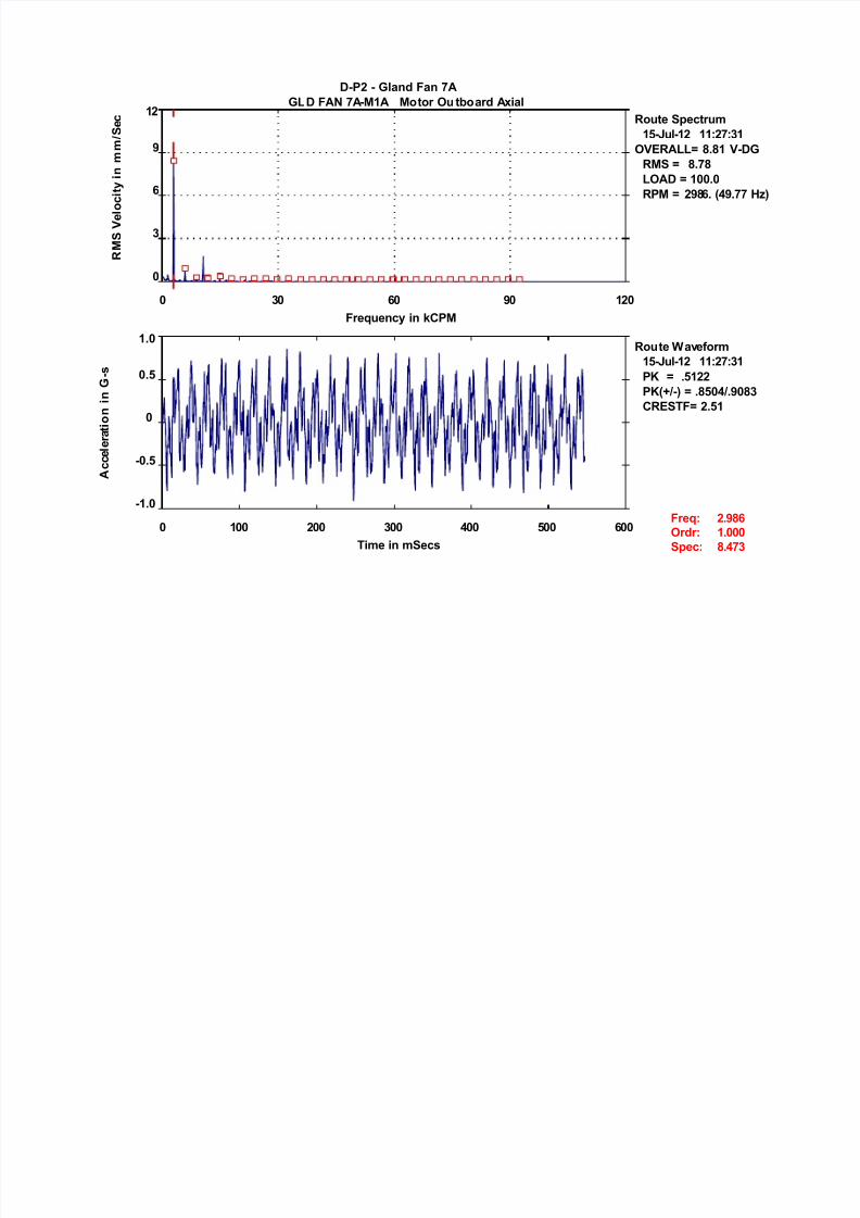
-P2 - la &a 7, &, 7,- 1, otor u t4oar , al
Route $6e*trum15-Jul-12 11:27:31
#R, = 8.81 -R $ = 8.78
, = 100.0RP = 2!8'. ( !.77 9)
0 30 '0 !0 120
0
3
'
!
12
&re ue *; <"P
R 2 $ 7 e l o * ( t ;
( ) m m
/ $ e *
&re :r r:
$6e*:
2.!8' 1.000 8. 73
8/19/2019 161 Axial Vibration
http://slidepdf.com/reader/full/161-axial-vibration 2/21
Route Waveform17-Jul-12 11:58:00PK = . 187PK(+/-) = .7'08/.7758"R#$%&= 2.'2
0 100 200 300 00 500 '00
-0.!
-0.'
-0.3
0
0.3
0.'
0.!
% me m$e*
, * * e l e r a t ( o )
( ) - +
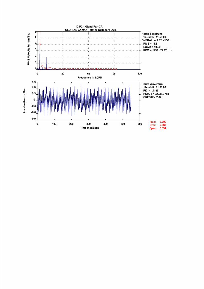
-P2 - la &a 7, &, 7,- 1, otor u t4oar , al
Route $6e*trum17-Jul-12 11:58:00#R, = .'2 -
R $ = .'1, = 100.0
RP = 1 50. (2 .17 9)
0 30 '0 !0 120
0
1
2
3
5
'
&re ue *; <"P
R 2 $ 7 e l o * ( t ;
( ) m m
/ $ e *
&re :r r:
$6e*:
3.000 2.0'! 3.8!
8/19/2019 161 Axial Vibration
http://slidepdf.com/reader/full/161-axial-vibration 3/21
Route Waveform15-Jul-12 11:28:01PK = .7358PK(+/-) = 1.15/1.0'"R#$%&= 2.21
0 100 200 300 00 500 '00
-1.5
-1.0
-0.5
0
0.5
1.0
1.5
% me m$e*
, * * e l e r a t ( o )
( ) - +
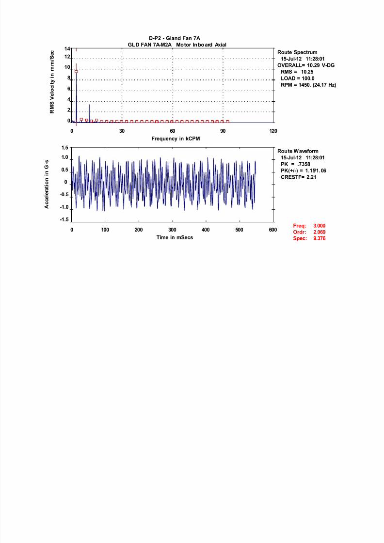
-P2 - la &a 7, &, 7,- 2, o tor 4o ar , al
Route $6e*trum15-Jul-12 11:28:01
#R, = 10.2! -R $ = 10.25, = 100.0
RP = 1 50. (2 .17 9)
0 30 '0 !0 120
0
2
'
8
10
121
&re ue *; <"P
R 2 $ 7 e l o * ( t ;
( ) m m
/ $ e *
&re :r r:
$6e*:
3.000 2.0'! !.37'

8/19/2019 161 Axial Vibration
http://slidepdf.com/reader/full/161-axial-vibration 4/21
Route Waveform17-Jul-12 11:58:5PK = . 315PK(+/-) = .!103/.8712"R#$%&= 2.!8
0 100 200 300 00 500 '00
-1.0
-0.5
0
0.5
1.0
% me m$e*
, * * e l e r a t ( o )
( ) - +
-P2 - la &a 7, &, 7,- 2, otor 4oar , al
Route $6e*trum17-Jul-12 11:58:5
#R, = 5.52 -R $ = 5.50, = 100.0
RP = 1 50. (2 .17 9)
0 30 '0 !0 120
0
1
2
3
5
'7
&re ue *; <"P
R 2 $ 7 e l o * ( t ;
( ) m m
/ $ e *
&re :r r:
$6e*:
3.000 2.0'! .!'1
8/19/2019 161 Axial Vibration
http://slidepdf.com/reader/full/161-axial-vibration 5/21
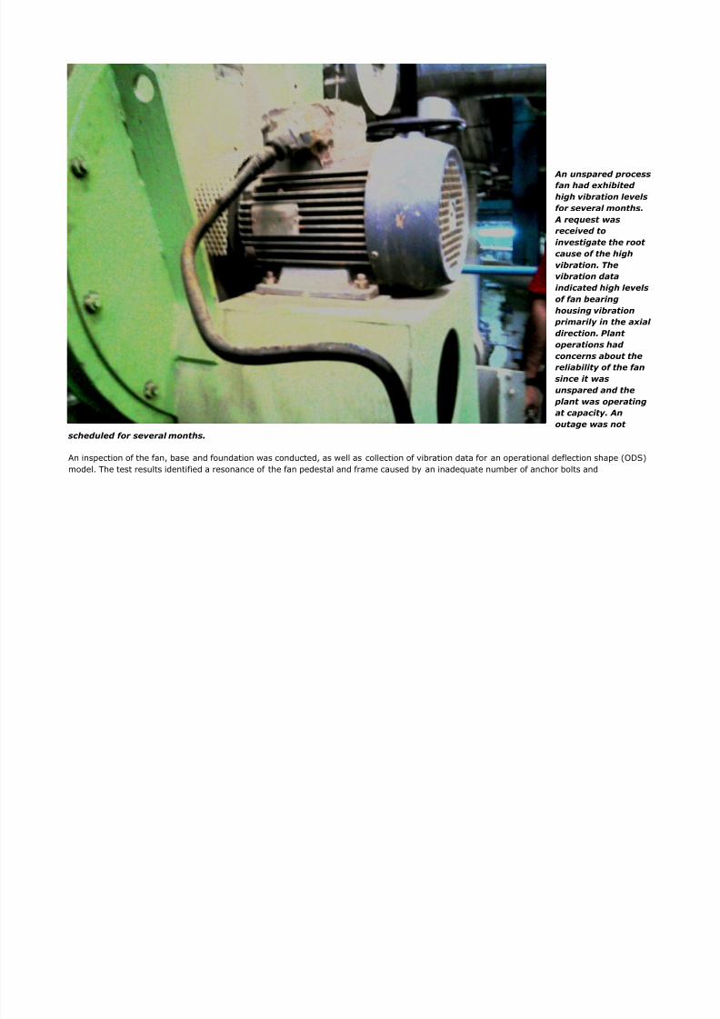
An unspared processfan had exhibitedhigh vibration levelsfor several months.
A request wasreceived toinvestigate the rootcause of the highvibration. Thevibration dataindicated high levelsof fan bearinghousing vibration
primarily in the axial direction. Plantoperations hadconcerns about thereliability of the fan
since it wasunspared and the
plant was operatingat capacity. Anoutage was not
scheduled for several months.
An inspection of the fan, base and foundation was conducted, as well as collection of vibration data for an operational deflection shape (ODS)model. The test results identified a resonance of the fan pedestal and frame caused by an inadequate number of anchor bolts and
8/19/2019 161 Axial Vibration
http://slidepdf.com/reader/full/161-axial-vibration 6/21
deteriorated rout. !nstallation of additional structural elements and anchor bolts alon with rout repair reduced vibration "# percent. Thisarticle describes the analysis process, findin s and modifications.
Background
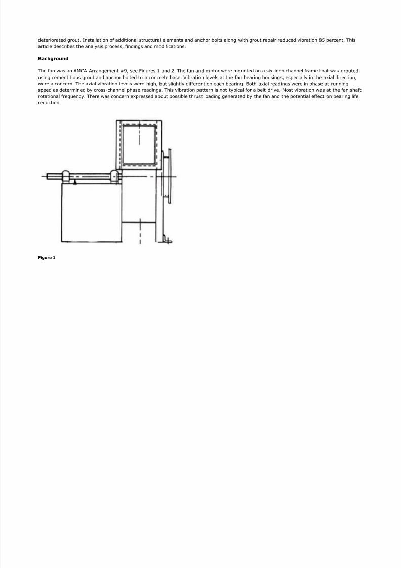
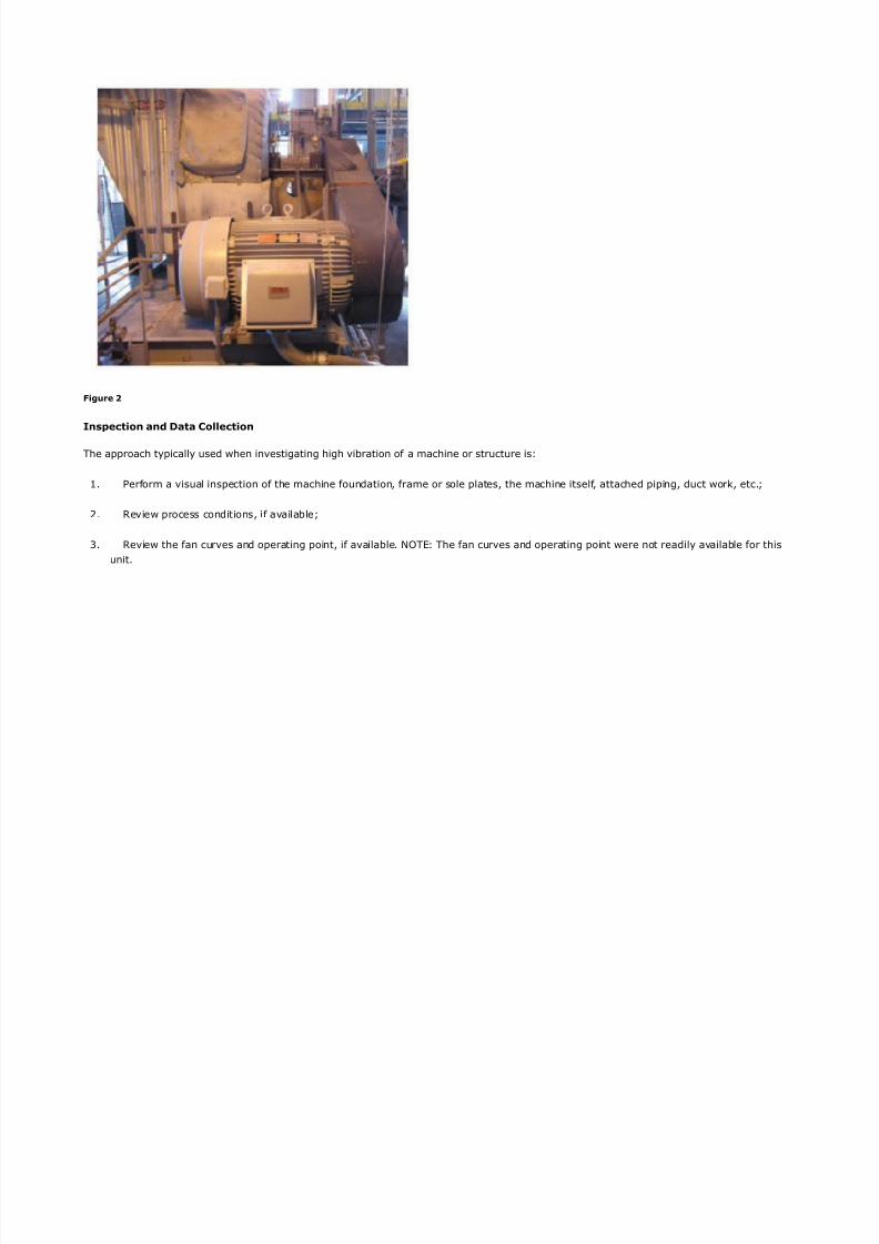
The fan was an A$%A Arran ement &', see i ures and *. The fan and motor were mounted on a si+ inch channel frame that was routedusin cementitious rout and anchor bolted to a concrete base. -ibration levels at the fan bearin housin s, especially in the a+ial direction,were a concern. The a+ial vibration levels were hi h, but sli htly different on each bearin . oth a+ial readin s were in phase at runninspeed as determined by cross channel phase readin s. This vibration pattern is not typical for a belt drive. $ost vibration was at the fan shaftrotational frequency. There was concern e+pressed about possible thrust loadin enerated by the fan and the potential effect on bearin lifereduction.
Figure 1
8/19/2019 161 Axial Vibration
http://slidepdf.com/reader/full/161-axial-vibration 7/21
8/19/2019 161 Axial Vibration
http://slidepdf.com/reader/full/161-axial-vibration 8/21
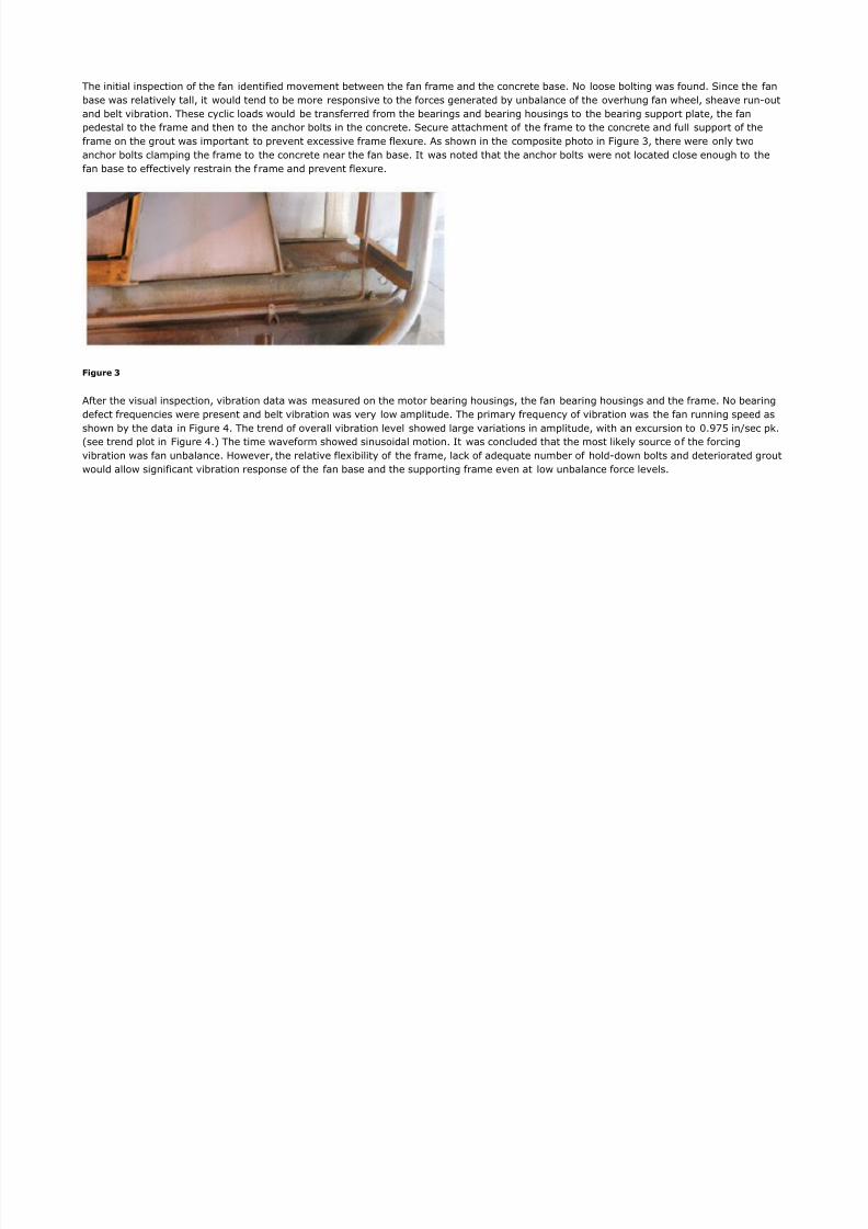
The initial inspection of the fan identified movement between the fan frame and the concrete base. 5o loose boltin was found. Since the fanbase was relatively tall, it would tend to be more responsive to the forces enerated by unbalance of the overhun fan wheel, sheave run outand belt vibration. These cyclic loads would be transferred from the bearin s and bearin housin s to the bearin support plate, the fanpedestal to the frame and then to the anchor bolts in the concrete. Secure attachment of the frame to the concrete and full support of theframe on the rout was important to prevent e+cessive frame fle+ure. As shown in the composite photo in i ure 4, there were only twoanchor bolts clampin the frame to the concrete near the fan base. !t was noted that the anchor bolts were not located close enou h to thefan base to effectively restrain the f rame and prevent fle+ure.
Figure 3
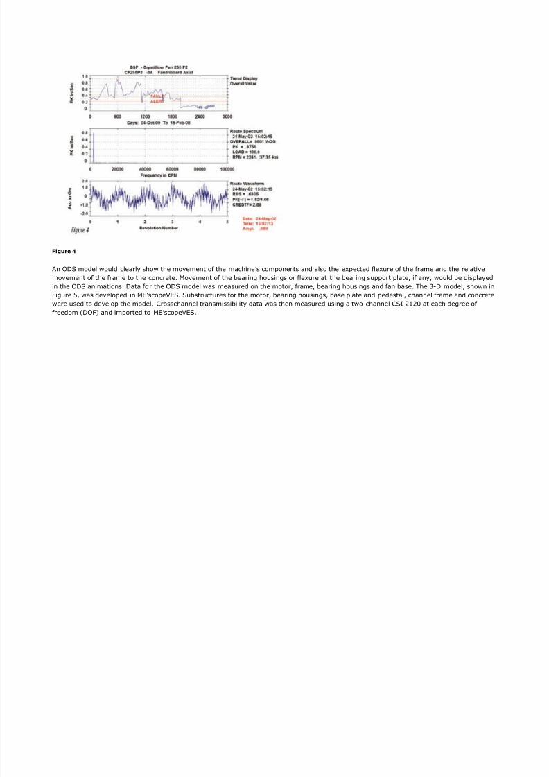
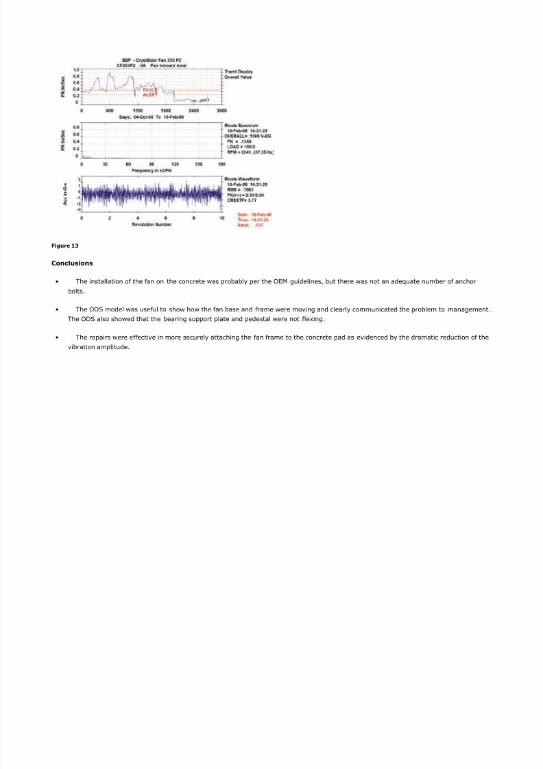
After the visual inspection, vibration data was measured on the motor bearin housin s, the fan bearin housin s and the frame. 5o bearindefect frequencies were present and belt vibration was very low amplitude. The primary frequency of vibration was the fan runnin speed asshown by the data in i ure 7. The trend of overall vibration level showed lar e variations in amplitude, with an e+cursion to 8.'9# in:sec p1.(see trend plot in i ure 7.) The time waveform showed sinusoidal motion. !t was concluded that the most li1ely source o f the forcin
vibration was fan unbalance. ;owever, the relative fle+ibility of the frame, lac1 of adequate number of hold down bolts and deteriorated routwould allow si nificant vibration response of the fan base and the supportin frame even at low unbalance force levels.
8/19/2019 161 Axial Vibration
http://slidepdf.com/reader/full/161-axial-vibration 9/21
Figure 4
An ODS model would clearly show the movement of the machine<s components and also the e+pected fle+ure of the frame and the relativemovement of the frame to the concrete. $ovement of the bearin housin s or fle+ure at the bearin support plate, if any, would be displayed
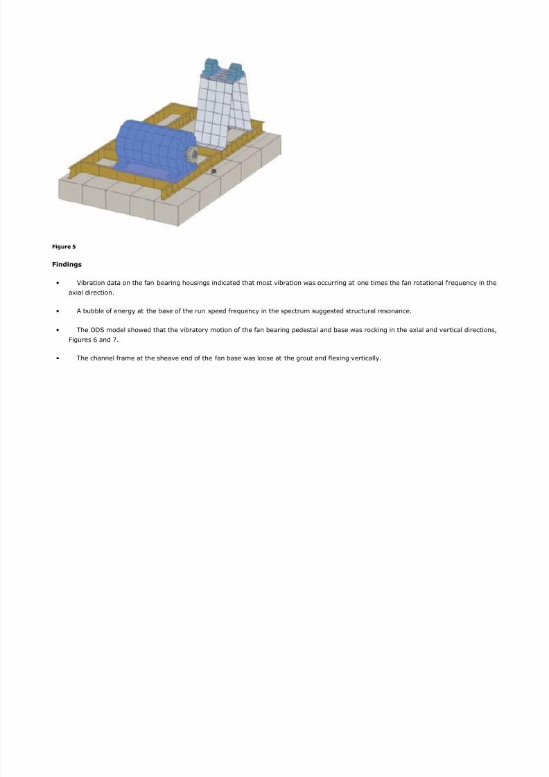
in the ODS animations. Data fo r the ODS model was measured on the motor, frame, bearin housin s and fan base. The 4 D model, shown ini ure #, was developed in $6<scope-6S. Substructures for the motor, bearin housin s, base plate and pedestal, channel frame and concrete
were used to develop the model. %rosschannel transmissibility data was then measured usin a two channel %S! * *8 at each de ree offreedom (DO ) and imported to $6<scope-6S.
8/19/2019 161 Axial Vibration
http://slidepdf.com/reader/full/161-axial-vibration 10/21
Figure 5
Findings
• -ibration data on the fan bearin housin s indicated that most vibration was occurrin at one times the fan rotational f requency in the
a+ial direction.
• A bubble of ener y at the base of the run speed frequency in the spectrum su ested structural resonance.
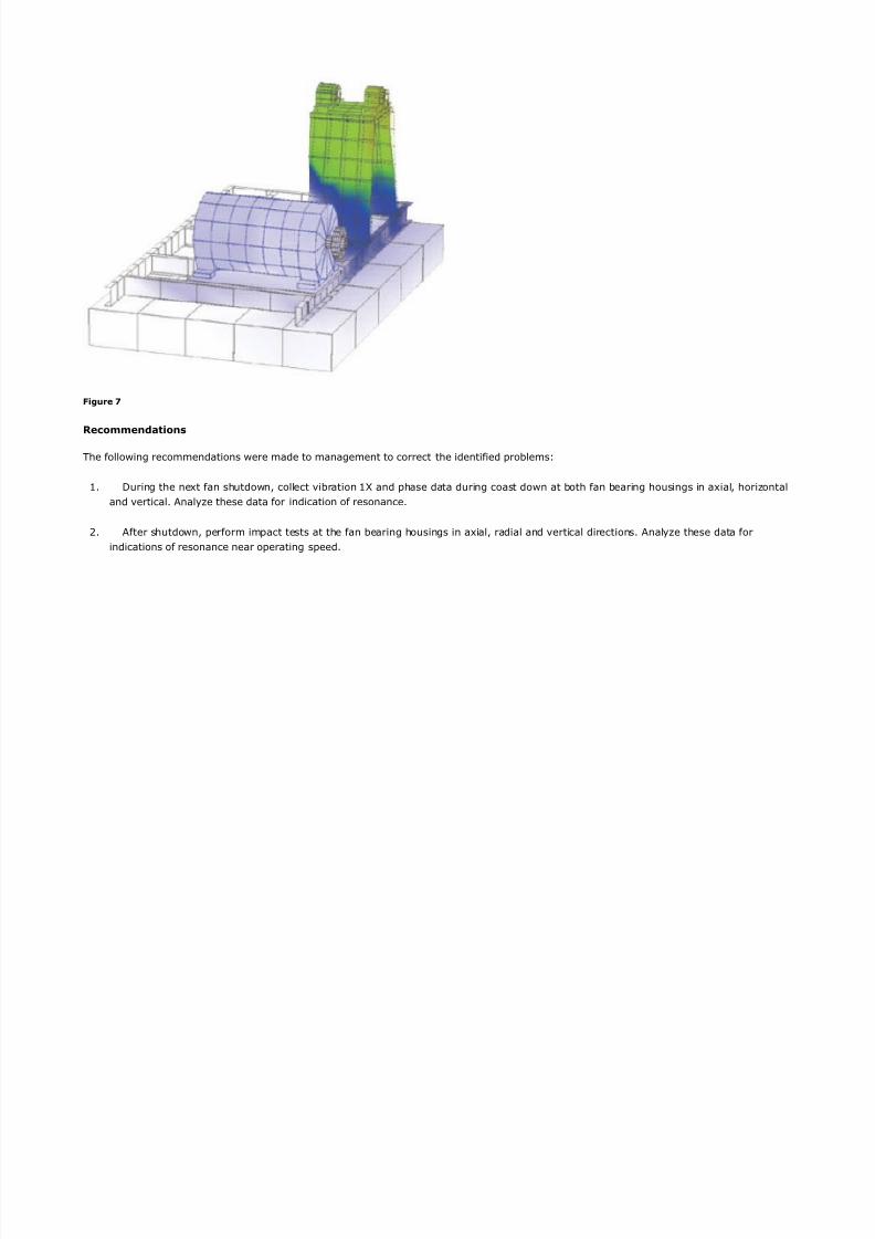
• The ODS model showed that the vibratory motion of the fan bearin pedestal and base was roc1in in the a+ial and vertical directions,
i ures = and 9.
• The channel frame at the sheave end of the fan base was loose at the rout and fle+in vertically.
8/19/2019 161 Axial Vibration
http://slidepdf.com/reader/full/161-axial-vibration 11/21
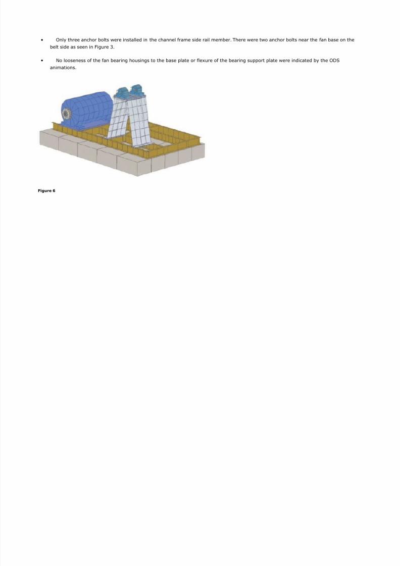
• Only three anchor bolts were installed in the channel frame side rail member. There were two anchor bolts near the fan base on the
belt side as seen in i ure 4.
• 5o looseness of the fan bearin housin s to the base plate or fle+ure of the bearin support plate were indicated by the ODS
animations.
Figure 6
8/19/2019 161 Axial Vibration
http://slidepdf.com/reader/full/161-axial-vibration 12/21
Figure 7
Recommendations
The followin recommendations were made to mana ement to correct the identified problems/
. Durin the ne+t fan shutdown, collect vibration > and phase data durin coast down at both fan bearin housin s in a+ial, hori?ontaland vertical. Analy?e these data for indication of resonance.
*. After shutdown, perform impact tests at the fan bearin housin s in a+ial, radial and vertical directions. Analy?e these data forindications of resonance near operatin speed.
8/19/2019 161 Axial Vibration
http://slidepdf.com/reader/full/161-axial-vibration 13/21
4. 3eview process historical data for fan as temperature and inlet uide vane settin s, if available, to determine if vibration levels arerelated to chan es in as density or flow rate.
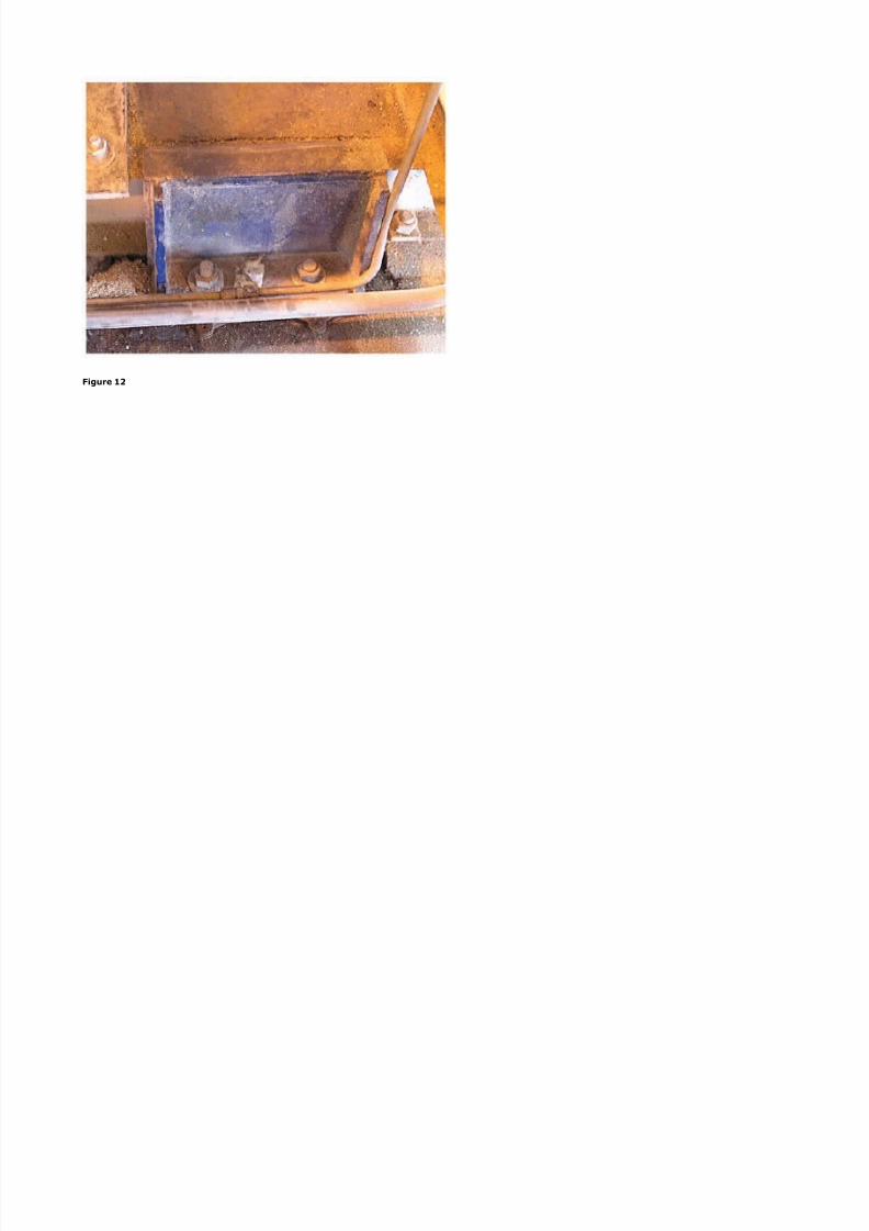
7. %hip rout from beneath the channel frame at the sheave end of the fan base.
#. 3eplace any carbon steel shims found between the concrete base and channel frame with stainless steel shims.
=. !nstall additional anchor bolts to secure the fan base and channel frame to the concrete. One method would use ;ilti brand twocomponent adhesive anchor bolts (or similar) in the concrete. Anchor bolts should be ti htened to securely clamp the fan base andchannel frame to the shims and concrete base, then replace the cementitious rout. %are should be ta1en to avoid chan in the positionof the channel, which could possibly chan e ali nment of the fan shaft to the mechanical air seal.
Follow up
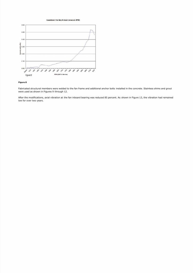
Durin shutdown of the fan, vibration data was collected usin a %S! * *8 two channel analy?er. 5ormal fan speed was **79 30$. The
amplitude and phase la versus rpm plot is shown in i ure ". The rapid vibration reduction and phase la an le chan e from 8.#8 to 8. 8in:sec p1 with =# de rees phase la an le chan e for the speed ran e **79 to '88 30$ confirmed the presence of a structural resonance.
8/19/2019 161 Axial Vibration
http://slidepdf.com/reader/full/161-axial-vibration 14/21
8/19/2019 161 Axial Vibration
http://slidepdf.com/reader/full/161-axial-vibration 15/21
Figure "
8/19/2019 161 Axial Vibration
http://slidepdf.com/reader/full/161-axial-vibration 16/21
Figure 1#
8/19/2019 161 Axial Vibration
http://slidepdf.com/reader/full/161-axial-vibration 17/21
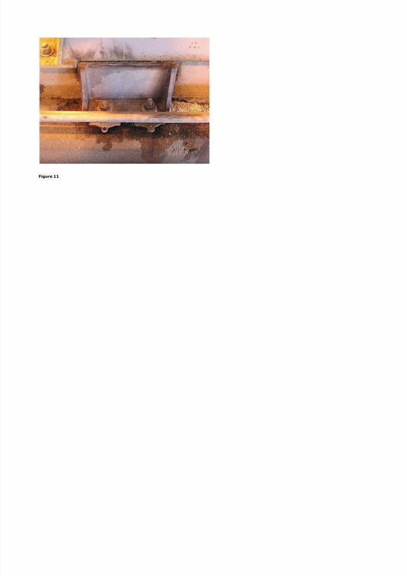
Figure 11
8/19/2019 161 Axial Vibration
http://slidepdf.com/reader/full/161-axial-vibration 18/21
Figure 12
8/19/2019 161 Axial Vibration
http://slidepdf.com/reader/full/161-axial-vibration 19/21
Figure 13
Conclusions
• The installation of the fan on the concrete was probably per the O6$ uidelines, but there was not an adequate number of anchor
bolts.
• The ODS model was useful to show how the fan base and frame were movin and clearly communicated the problem to mana ement.The ODS also showed that the bearin support plate and pedestal were not fle+in .
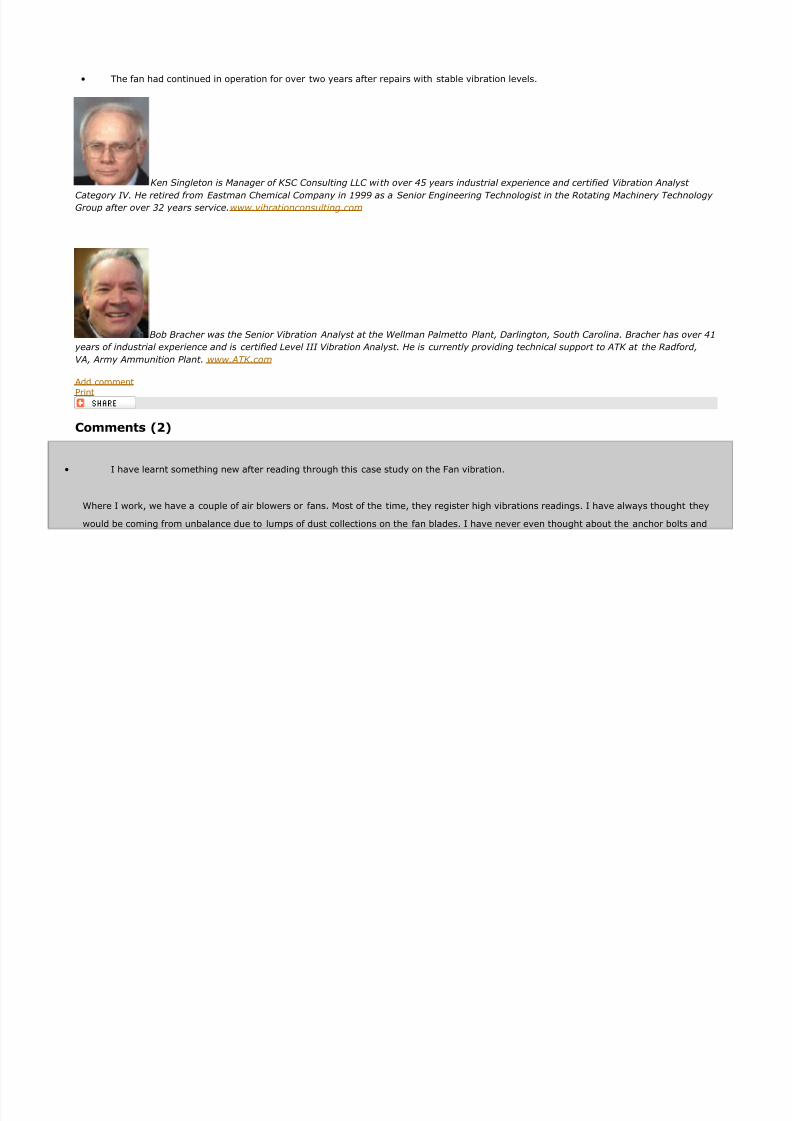
• The repairs were effective in more securely attachin the fan frame to the concrete pad as evidenced by the dramatic reduction of the
vibration amplitude.
8/19/2019 161 Axial Vibration
http://slidepdf.com/reader/full/161-axial-vibration 20/21
8/19/2019 161 Axial Vibration
http://slidepdf.com/reader/full/161-axial-vibration 21/21