Embed Size (px)
Citation preview
H214 Journal of The Electrochemical Society, 161 (4) H214-H219 (2014)0013-4651/2014/161(4)/H214/6/$31.00 © The Electrochemical Society
Hydrophobic Electrolyte Pastes for Highly Durable Dye-SensitizedSolar CellsTzu-Chien Wei,a,∗,z Han-Hsu Chen,b Ya-Huei Chang,c and Shien Ping Fengc
aDepartment of Chemical Engineering, National Tsing-Hua University, Hsin-Chu, TaiwanbDivision of R&D, Tripod Technology Corporation, Ping-Jen, TaiwancDepartment of Mechanical Engineering, The University of Hong Kong, Hong Kong
In this study, we report a simple but efficient way to improve the thermal stability of a dye-sensitized solar cell by adding a smallamount of commercial silica nano-powders in a non-volatile electrolyte system. The paste-like electrolyte not only shows betterwater repellence because of the hydrophobicity of silica powder but also allows film casting for replacing conventional injectionprocess. Compared with the device using liquid type electrolyte or paste-like electrolyte using hydrophilic nano-powders, the deviceusing hydrophobic paste shows superior thermal stability without costly sealing and extra encapsulation.© 2014 The Electrochemical Society. [DOI: 10.1149/2.057404jes] All rights reserved.
Manuscript submitted November 6, 2013; revised manuscript received January 9, 2014. Published February 11, 2014.
Dye-sensitized solar cell (DSSC) is a promising photovoltaic tech-nology which provides low cost solar electricity and shows uniqueperformance under low illumination.1–4 In the past 2 decades, tremen-dous efforts have been done on the synthesis of more efficient dyes,5–7
preparation of TiO2 mesoporous film structures with faster electrontransportation and slower recombination rate,8,9 more stable and effi-cient electrolyte systems10,11 and exploring earth-abundant materialswith good catalytic activities for redox couple regeneration.12–15 Todate, the power conversion efficiency (PCE) of DSSCs has reached12.4% for devices sensitizing with a zinc porphyrin and cobalt basedredox electrolyte.16 Despite the gap in PCE between the DSSC andmature silicon photovoltaic diminishes rapidly, the practicability of aDSSC remains debatable.
One of the major concerns of DSSCs for practical use is the long-time stability, which can be discussed from the following three aspects:
(1) Reliability of sealing materials or effectiveness of encapsulationstructures during long-time sunlight exposure.
(2) Self-degradation of active components such as dyes, redox cou-ples or counter electrodes inside a DSSC after hundreds of thou-sands operations.
(3) Poisoning of active components due to intrusion of externalmaterials such as oxygen or water.
Lots of symptoms are reported in a degraded DSSC. For instance,unreliable sealing usually leads to photo-current decay due to dry-out of the electrolyte, particularly in the device using low boiling-point organic solvent like acetonitrile (AN) even in a short period oftesting. In addition, for DSSCs equipped with dyes containing mono-dentate thiocyanate ligands (NCS) such as N719, it is usually observedsignificant photo-voltage decay in the accelerated aging test, which isa result of substitution reaction between dyes and solvents or additivesdue to weak bonding of NCS ligand;17,18 moreover, it has been reportedthat water content in a DSSC plays an important role on the stability ofa DSSC, Matsui and et al19 reported the water content should be lowerthan 1% to maintain the performance of a DSSC during acceleratedthermal test; otherwise the dye will be detached or degraded. Kato andet al.20 studied long-term stability of monolithically connected DSSCunder outdoor working condition and concluded that the decrease oftri-iodide in the electrolyte due to the irreversible reaction betweentri-iodide and intruded water is the root cause of the degradation. Theyalso suggest that an additional sealing and encapsulation of the DSSCis necessary to obtain a satisfactory durability.
To surmount above problems, several prescriptions have been pro-posed including replacing volatile AN with low viscous, non-volatileionic liquid (NVIL) to eliminate the volatilization of electrolytesystem;21,22 designing new dyes equipped with stronger bonding tometal center such as azolate derivatives23–25 to prevent them from
∗Electrochemical Society Active Member.zE-mail: [email protected]
self-decomposition and applying additional encapsulation structureto defense water intrusion under various operating conditions.26–28
These efforts are of course beneficial to the long-term stability of aDSSC, but on the other hand, they also sacrifice certain advantages of aDSSC such as of low cost materials or simple manufacture processes.
In order to alleviate the leakage of electrolyte, solidifying non-volatile ionic liquid electrolyte (NVILE) by dispersing a small amountof inorganic nano-powders29–31 or polymers32,33 in to NVILE is apromising method; in particular, mixing inorganic nano-powders suchas TiO2 with NVILE to form so called “ionic gel” is found to havebetter PCE than its original NVILE.27 However, the discussion of thehydrophilicities of nano-powders on the performance or stability ofDSSC is absent.
Aiming to find out a simple way to obtain a durable DSSC, wedevelop a printable electrolyte paste by adding a few amount (5%w.t%) of commercially-available, hydrophobic SiO2 nano-powder ina liquid NVILE to form a gel and then centrifuging the gel to obtain theclay-like non-volatile ionic paste (NVIP). The hydrophobic SiO2 in thepaste is found to serve as an efficient water repellent inside the paste.Compared with liquid type or other NVIPs composed of hydrophilicnano-powders, it exhibits excellent stability on the accelerated thermaltest under 60◦C over 1000 hours. Moreover, this hydrophobic NVIP isviscous enough for direct applying on photo-anode by various coatingtechniques so the tedious process relating to electrolyte injection inconventional liquid or quasi-solid type electrolyte such as hole drilling,injecting and hole sealing can be omitted or significantly simplified.
Experimental
Preparation of the mesoporous TiO2 photoanode.— A tri-layerfilm containing TiO2 under-layer, mesoporous and light scatteringlayer was prepared as follows: FTO glass (TEC11, Nippon SheetGlass) was cleaned and dried before it was immersed into a 40 mMTiCl4 aqueous solution at 70◦C for 30 min followed by washing withwater and ethanol, the purpose of this treatment was to form a thinand dense TiO2 underlayer to suppress dark current at this interface;then TiO2 paste (Eternal, 2105, solid content 18%, mean particlesize 20 nm) was repeatedly screen-printed on the TiCl4-treated FTOglass until the film thickness was 7 μm. Finally, light scattering paste(CCIC, PST400) was screen-printed over 7 μm-TiO2 film to make thetotal thickness of this tri-layer film was ca. 9 μm.
The tri-layer film was then sintered at 500◦C for 30 minutes in afurnace. In order to enhance the interconnection of the TiO2 nano-particles, the film was placed into a 40 mM TiCl4 solution at 70◦C for30 min again. After washed with water and ethanol, it was annealedagain at 450◦C for 30 min to complete the photo-anode preparation.Before dye soaking, a patterned hot-melt film (Surlyn, 30 μm, DuPont)was firstly attached on the photo-anode to facilitate electrolyte cast-ing in later step. Finally dye soaking was done by immersing the
) unless CC License in place (see abstract). ecsdl.org/site/terms_use address. Redistribution subject to ECS terms of use (see 158.132.160.61Downloaded on 2014-11-12 to IP
Journal of The Electrochemical Society, 161 (4) H214-H219 (2014) H215
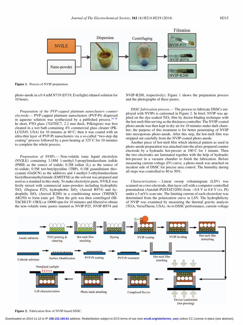
Figure 1. Process of NVIP preparation.
photo-anode in a 0.4 mM N719 (D719, Everlight) ethanol solution for10 hours.
Preparation of the PVP-capped platinum nanoclusters counterelectrode.— PVP-capped platinum nanoclusters (PVP-Pt) dispersedin aqueous solution was synthesized by a published process.34–36
In short, FTO glass (7�/TEC7, 2.2 mm thick, Pilkington) was firstcleaned in a wet bath containing 4% commercial glass cleaner (PK-LCG545, USA) for 10 minutes at 40◦C; then it was coated with anultra-thin layer of PVP-Pt nanoclusters via a so-called “two-step dipcoating” process followed by a post heating at 325◦C for 10 minutesto complete the whole process.
Preparation of NVIPs.— Non-volatile ionic liquid electrolyte(NVILE) containing 3.18M 1-methyl-3-propylimidazolium iodide(PMII) as the source of iodide; 0.2M iodine (I2) as the source oftri-iodide; 0.5M tert-butylpyridine (TBP), 0.1M guanidinium thio-cyanate (GuSCN) as the additives and 1-methyl-3-ethylimidazoliumbis(trifluoromethyl)imide (EMITFSI) as the solvent was prepared andused as a standard in this study. To make electrolyte paste, NVILE wasfirstly mixed with commercial nano-powders including hydrophilicTiO2 (Degussa P25), hydrophobic SiO2 (Aerosil R974) and hy-drophilic SiO2 (Aerosil R200) in a conditioning mixer (THINKYAR250) to form ionic gel. Then the gels was then centrifuged (HI-TACHI CF-15RX) at 10000 rpm for 10 minutes and filtered to obtainthe non-volatile ionic pastes (named as NVIP-P25, NVIP-R974 and
NVIP-R200, respectively). Figure 1 shows the preparation processand the photographs of these pastes.
DSSC fabrication process.— The process to fabricate DSSCs em-ployed with NVIPs is cartooned in Figure 2. In brief, NVIP was ap-plied on the dye-soaked TiO2 film by doctor-blading technique withthe hot-melt film serving as the thickness controller. The NVIP-coatedphoto-anode was then kept in dry air for 10 minutes under dark cham-ber; the purpose of this treatment is for better penetrating of NVIPinto mesoporous photo-anode. After this step, the hot-melt film wasstripped out carefully from the NVIP-coated photo-anode.
Another piece of hot-melt film which identical pattern as used inphoto-anode preparation was attached onto the afore-prepared counterelectrode by a hydraulic hot-presser at 100◦C for 1 minute. Thenthe two electrodes are laminated together with the help of hydraulichot-presser in a vacuum chamber to finish the fabrication. Beforemeasuring current-voltage (IV) curve, a photo-mask was attached onincident side of DSSC for precise area control. The humidity duringall steps was controlled to 40 to 50%.
Characterization.— Linear sweep voltammgram (LSV) wasscanned on a two-electrode, thin layer cell with a computer-controlledpotentialstat (Autolab PGSTAT320N) from −0.8 V to 0.8 V (vs. Pt)under a 5 mV/s scan rate. The limiting current of each electrolyte wasdetermined from the polarization curve in LSV. The hydrophilicityof NVIP was examined by measuring the thermal gravity analysis(TGA, VersaTherm, USA). As to DSSC performance, current-voltage
Figure 2. Fabrication flow of NVIP-based DSSC.
) unless CC License in place (see abstract). ecsdl.org/site/terms_use address. Redistribution subject to ECS terms of use (see 158.132.160.61Downloaded on 2014-11-12 to IP
H216 Journal of The Electrochemical Society, 161 (4) H214-H219 (2014)
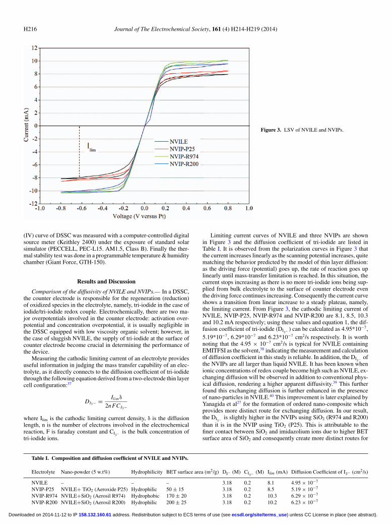
Figure 3. LSV of NVILE and NVIPs.
(IV) curve of DSSC was measured with a computer-controlled digitalsource meter (Keithley 2400) under the exposure of standard solarsimulator (PECCELL, PEC-L15. AM1.5, Class B). Finally the ther-mal stability test was done in a programmable temperature & humiditychamber (Giant Force, GTH-150).
Results and Discussion
Comparison of the diffusivity of NVILE and NVIPs.— In a DSSC,the counter electrode is responsible for the regeneration (reduction)of oxidized species in the electrolyte, namely, tri-iodide in the case ofiodide/tri-iodide redox couple. Electrochemically, there are two ma-jor overpotentials involved in the counter electrode: activation over-potential and concentration overpotential, it is usually negligible inthe DSSC equipped with low viscosity organic solvent; however, inthe case of sluggish NVILE, the supply of tri-iodide at the surface ofcounter electrode become crucial in determining the performance ofthe device.
Measuring the cathodic limiting current of an electrolyte providesuseful information in judging the mass transfer capability of an elec-trolyte, as it directly connects to the diffusion coefficient of tri-iodidethrough the following equation derived from a two-electrode thin layercell configuration:37
DI3− = Ilimδ
2nFCI3−
where Ilim is the cathodic limiting current density, δ is the diffusionlength, n is the number of electrons involved in the electrochemicalreaction, F is faraday constant and CI3− is the bulk concentration oftri-iodide ions.
Limiting current curves of NVILE and three NVIPs are shownin Figure 3 and the diffusion coefficient of tri-iodide are listed inTable I. It is observed from the polarization curves in Figure 3 thatthe current increases linearly as the scanning potential increases, quitematching the behavior predicted by the model of thin layer diffusion:as the driving force (potential) goes up, the rate of reaction goes uplinearly until mass-transfer limitation is reached. In this situation, thecurrent stops increasing as there is no more tri-iodide ions being sup-plied from bulk electrolyte to the surface of counter electrode eventhe driving force continues increasing. Consequently the current curveshows a transition from linear increase to a steady plateau, namely,the limiting current. From Figure 3, the cathodic limiting current ofNVILE, NVIP-P25, NVIP-R974 and NVIP-R200 are 8.1, 8.5, 10.3and 10.2 mA respectively; using these values and equation 1, the dif-fusion coefficient of tri-iodide (DI3− ) can be calculated as 4.95*10−7,5.19*10−7, 6.29*10−7 and 6.23*10−7 cm2/s respectively. It is worthnoting that the 4.95 × 10⁻⁷ cm2/s is typical for NVILE containingEMITFSI as the solvent,38 indicating the measurement and calculationof diffusion coefficient in this study is reliable. In addition, the DI3− ofthe NVIPs are all larger than liquid NVILE. It has been known whenionic concentrations of redox couple become high such as NVILE, ex-changing diffusion will be observed in addition to conventional phys-ical diffusion, rendering a higher apparent diffusivity.39 This furtherfound this exchanging diffusion is further enhanced in the presenceof nano-particles in NVILE.40 This improvement is later explained byYanagida et al27 for the formation of ordered nano-composite whichprovides more distinct route for exchanging diffusion. In our result,the DI3− is slightly higher in the NVIPs using SiO2 (R974 and R200)than it is in the NVIP using TiO2 (P25). This is attributable to thefiner contact between SiO2 and imidazolium ions due to higher BETsurface area of SiO2 and consequently create more distinct routes for
Table I. Composition and diffusion coefficient of NVILE and NVIPs.
Electrolyte Nano-powder (5 w.t%) Hydrophilicity BET surface area (m2/g) DI− (M) CI3− (M) Ilim (mA) Diffusion Coefficient of I3− (cm2/s)
NVILE – – – 3.18 0.2 8.1 4.95 × 10⁻⁷
NVIP-P25 NVILE+ TiO2 (Aeroxide P25) Hydrophilic 50 ± 15 3.18 0.2 8.5 5.19 × 10⁻⁷
NVIP-R974 NVILE+SiO2 (Aerosil R974) Hydrophobic 170 ± 20 3.18 0.2 10.3 6.29 × 10⁻⁷
NVIP-R200 NVILE+SiO2 (Aerosil R200) Hydrophilic 200 ± 25 3.18 0.2 10.2 6.23 × 10⁻⁷
) unless CC License in place (see abstract). ecsdl.org/site/terms_use address. Redistribution subject to ECS terms of use (see 158.132.160.61Downloaded on 2014-11-12 to IP

Journal of The Electrochemical Society, 161 (4) H214-H219 (2014) H217
Figure 4. Schematic pathways of NVIP-P25 and NVIP-R974 or R200.
exchanging diffusion; this mechanism is further enhanced since thespace between every specie in NVIPs shrinks in a significant mannerafter centrifugation. The schematic for ionic pathways of NVIP-P25and NVIP-R974 or NVIP-R200 nano-composites are illustrated inFigure 4.
Comparison of performance of DSSC composed of NVIPs.— Fig-ure 5 is the photographs of NVIPs and the corresponding devices. Itcan be seen on Figure 5 the non-fluidity appearance of the device;one thing worth noting is there are no injection holes on the counterelectrode side in these devices and this property is expected to bene-ficial in the stability test. Figure 6 is the IV curves DSSCs composedof NVILE and NVIPs and the IV parameters including short circuitcurrent density (JSC), open circuit voltage (VOC), fill factor (FF) andPCE of these curves are summarized in Table II. It can be seen that thePCE of DSSC using NVILE is 4.69%, we regard this as a benchmarkfor comparison. When NVILE is solidified, the PCEs increase from4.69% to 5.21%, 5.39% and 5.31% in the case of NVIP-P25, NVIP-R974 and NVIP-R200, respectively. As shown in Table II, JSC arerelatively stable in all samples, suggesting the solidified electrolyteshave negligible influence on the performance of photo-anode; a fur-ther interpretation of this result hints that the penetration of NVIPsin the ca. 9 μm deep TiO2 film is basically satisfactory. The increaseof PCE is then attributed to the improvement of VOC and FF. Wespeculate the improvement on VOC is due to that tri-iodides has beenconfined in the nano-composite so that the charge recombination issuppressed; while the significant FF improvement can be attributedto higher diffusivity if tri-iodide and consequently lower the internalresistance. The highest PCE, 5.39%, in this study is obtained in thesample using NVIP-R974.
Figure 5. Photographs of NVIPs and DSSC employed with these NVIPs,showing no injection hole is needed in this system.
Figure 6. IV curves of DSSC employed with NVILE and NVIPs.
Comparison of thermal stability of DSSC composed of differentNVIPs.— One of the major purposes of solidifying liquid electrolyteis to minimize the leakage of the electrolyte during prolonged storageso that the durability of DSSC can be improved. It is therefore the ther-mal stability of NVIP-DSSCs are examined. The test was conductedby placing as-prepared DSSCs employed with NVILE and NVIPswithout any additional sealing or encapsulation in a 60◦C oven con-stantly and measuring the IV curves every 100 hour until total agingtime reaching 1000 hours. Figure 7 is the curves of IV parametersvariation. It can be found that while the PCE of DSSCs using NVIPsshow minor different, their behaviors in thermal aging test exhibitsignificantly distinct. For DSSC employed with NVILE, the VOC andJSC decayed in the initial 200 hours by about 10%; the decay of VOC
is attributable for the evaporation of TBP28 and decrease of JSC is aresult of water intrusion.27 After 200 hours, the VOC decay alleviatedor even recovered, this can be explained by the fact of continuousdecrease of JSC, meaning the redox couples are constantly depleted byintruded water and as a result, the charge recombination reaction in theTiO2/Dye/tri-iodide is slows down due to insufficient tri-iodide con-centration. The FF increase 10% in the entire test is another evidenceof water intrusion, since water is a better solvent than EMITFSI forall ingredients in NVILE. In the end, DSSC employed with NVILEgave an acceptable stability of overall 13% PCE decay.
When the electrolyte system shifted to NVIPs, the behaviors wentto a surprising result. A first glimpse in Figure 7 for the stabilitiesfor DSSC employed with 3 NVIPs is that NVIP-R974 performedextremely robustly, while NVIP-P25 shows much fast decay. Learn-ing from the experience in NVILE, we understand water content isa key factor in determining a DSSC’s durability. To investigate thewater content in NVIPs, we arranged an off-line test by placing sameamount NVIP-P25, NVIP-R974 and NVIP-R200 in three uncoveredcontainers for water absorption under open-air condition for 1 weeks.The water content in each sample is then measured by thermogravi-metric analysis (TGA) shown in Figure 8. Analyzed from Figure 8, thewater contents in NVIP-P25, NVIP-R974 and NVIP-R200 are 9.5%,5.5% and 7.5%, respectively. Although the result cannot represent
Table II. IV parameters of DSSCs employed with NVILE andNVIPs.
Electrolyte JSC (mA/cm2) VOC (V) FF PCE (%)
NVILE 11.18 0.65 0.64 4.69NVIP-P25 11.40 0.65 0.69 5.21NVIP-R974 11.07 0.69 0.71 5.39NVIP-R200 11.08 0.67 0.71 5.31
) unless CC License in place (see abstract). ecsdl.org/site/terms_use address. Redistribution subject to ECS terms of use (see 158.132.160.61Downloaded on 2014-11-12 to IP

H218 Journal of The Electrochemical Society, 161 (4) H214-H219 (2014)
Figure 7. Stability test of DSSC employed with NVILE and NVIPs.
actual water amount in the DSSC employed with NVIPs, it still pro-vides useful information on the degree of water intrusion during thethermal stability test since there are no additional sealing structuresexcept a piece of hot-melt film. R974 is hydrophobic and when envi-ronmental moisture entered the cell through the hot-melt film duringthe thermal stability test, R974 could serve as a repellant to preventmoisture from reacting with redox species or dye cations; on the con-trary, P25 and R200 are both hydrophilic and expected to worsen thewater effect.
Knowing the relation between hydrophilicity and water contentin NVIPs provides straight forward explanation to the thermal stabil-ity test. DSSC employed with NVIP-R974 showed negligible loss onJSC over 1000 hours at 60◦C, indicating the water impact has beensignificantly suppressed; meanwhile, FF also maintained very steady,
Figure 8. TGA curves of various NVIPs exposed in air for 1 week.
Figure 9. Stability test of R974 based DSSC using N719 and Z907 assensitizers.
proving that the composition of NVIP-R974 was not affected by in-truded water during the whole test. Although VOC suffered from 2%loss because of TBP evaporation, PCE maintained astonishingly sta-ble (decayed from highest point, 5.57% to end point, 5.44%). To ourknowledge, this is a very impressive performance for the device with-out secondary sealing or external encapsulation. For the case of NVIP-R200 and NVIP-P25, once water is penetrated from atmosphere, theyare expected to attract intruded water due to the hydrophilic natureand then deplete tri-iodide. As a result, the JSC dropped monotonouslythrough the whole test. The final PCE of DSSC employed with NVIP-R200 is somewhat better than that of DSSC employed with NVIP-P25,this is probably due phase separation of NVIP-P25 was observed dur-ing the latter half of the test, while NVIP-R200 remained gel-like inthe entire test period.
Test on the thermal stability of NVIP-R974-based DSSC composedof different sensitizers.— Until now, the dye used in this study is Z907,which is known to more stable than N3 or N719 in the presence ofwater due to the introduction of aliphatic chains.41 Since NVIP-R974is also made hydrophobic and NVIP-R974 based DSSC using Z907 assensitizer performed extremely thermally stable as discussed above, itis interesting how it will perform if the moisture-sensitive N719 is em-ployed. Hence the NVIP-R974 based DSSC using N719 as sensitizerwas fabricated and the thermal aging test was repeated. The result wascompared in Figure 9. It can be seen that after 111 days continuousaging at 60◦C, the PCE of Z907-R974 maintained 97% of its initialvalue, indicating the combination of two hydrophobic ingredients,Z907 sensitizer and NVIP-R974 electrolyte, in a DSSC can signifi-cantly minimize the impact of hazardous water so that it can maintainthermally stable at 60◦C over more than 2664 hours under a very sim-ple sandwiched sealing structure. In the case of the hydrophilic N719
) unless CC License in place (see abstract). ecsdl.org/site/terms_use address. Redistribution subject to ECS terms of use (see 158.132.160.61Downloaded on 2014-11-12 to IP

Journal of The Electrochemical Society, 161 (4) H214-H219 (2014) H219
is used, the device still showed considerable thermal stability of 19.5%decay from its initial PCE at 60◦C over more than 2644 hours. Thisresult indicates that the introduction of hydrophobic nano-powderin the electrolyte like NVIP-R974 can provide acceptable durabil-ity of simple-sealed DSSC, even in the existence of water-sensitivesensitizer.
Conclusions
In conclusion, we have developed NVIPs by introducing commer-cial inorganic nano-powder in NVILEs. The NVIP is so viscous so thesteps involving electrolyte applying such as hole drilling, electrolyteinjecting and hole sealing can be replaced with a singular doctor-blading or similar casting techniques. Meanwhile, we also obtainedvery robust 5.39% energy conversion efficiency at 1 sun conditionby employing both a hydrophobic R974 and a hydrophobic Z907sensitizer. The durability of the device is found to connect with thesuperior water repellence of R974 and as a result, the unwanted re-action between active species and intruded water can be suppressed.This repellent property is also helpful to the thermal stability of aN719 based DSSC. The observed stable performance of R974-basedDSSC can further stimulate the practical applications and reduce themanufacturing cost of DSSC. Future application of this material willbe focused on the improvement of stability on plastic DSSC system.
Acknowledgments
The authors thank the National Science Council of Taiwan (ProjectNo. 102-2221-E-007-121) and Academia Sinica of Taiwan (ProjectNo. AS-102-SS-A11) for their financial support.
References
1. B. O’Regan and M. Gratzel, Nature, 353, 737 (1991).2. M. K. Nazeeruddin, A. Kay, R. Humphry-Baker, E. Muller, P. Liska,
N. Vlachopoulos, and M. Gratzel, J. Am. Chem. Soc., 115, 6382 (1993).3. A. Hagfeldt, G. Boschloo, L. Sun, L. Kloo, and H. Pettersson, Chem. Rev., 110, 6595
(2010).4. S. Ito, H. Matsui, K. Okada, S. Kusano, T. Kitamura, Y. Wada, and S. Yanagida, Sol.
Energy Mater. Sol. Cells, 82, 421 (2004).5. P. Wang, C. Klein, R. H. Baker, S. M. Zakeeruddin, and M. Gratzel, J. Am. Chem.
Soc., 127, 809 (2005).6. Q. Yu, S. Liu, M. Zhang, N. Cai, Y. Wang, and P. Wang, J. Phys. Chem. C, 113, 14559
(2009).7. J. G. Chen, C. Y. Chen, S. J. Wu, J. Y. Li, C. G. Wu, and K. C. Ho, Sol. Energy Mater.
Sol. Cells, 92, 1723 (2008).8. M. K. Nazeeruddin, P. Pechy, and M. Gratzel, Chem. Commun., 1705 (1997).9. S. Ito, P. Liska, P. Comte, R. Charvet, P. Pechy, U. Bach, L. Schmidt-Mende,
S. M. Zakeeruddin, A. Kay, M. K. Nazeeruddin, and M. Gratzel, Chem. Commun.,34, 4351 (2005).
10. P. Wang, S. M. Zakeeruddin, R. Humphry-Baker, and M. Gratzel, Chem. Mater., 16,2694 (2004).
11. P. Wang, C. Klein, R. Humphry-Baker, S. M. Zakeeruddin, and M. Gratzel, Appl.Phys. Lett., 86, 123508 (2005).
12. X. Lin, M. Wu, Y. Wang, A. Hagfeldt, and T. Ma, Chem. Commun., 47, 11489 (2011).13. T. C. Wei, C. C. Wan, Y. Y. Wang, C. M. Chen, and H. S. Shiu, J. Phys. Chem. C,
111(12), 4847 (2007).14. T. N. Murakami, S. Ito, Q. Wang, M. K. Nazeeruddin, T. Bessho, I. Cesar, P. Liska,
R. Humphry-Baker, P. Comte, P. Pechy, and M. Gratzel, J. Electrochem. Soc., 153,A2255 (2006).
15. L. Kavan, J. H. Yum, M. K. Nazeeruddin, and Michael Graetzel, ACS Nano, 5, 9171(2011).
16. A. Yella, H. Lee, H. Tsao, C. Yi, A. Chandiran, M. K. Nazeeruddin, E. Diau, C. Yeh,S. M. Zakeeruddin, and M. Gratzel, Science, 334, 4 (2011).
17. H. T. Nguyen, H. M. Ta, and T. Lund, Sol. Energy Mater. Sol. Cells, 91, 1934 (2007).18. C. Yoshida, S. Nakajima, Y. Shoji, E. Itoh, K. Momiyama, K. Kanomata, and
F. Hirose, J. Electrochem. Soc., 159, H881 (2012).19. H. Arakawa1, T. Yamaguchi1, K. Okada, H. Matsui, T. Kitamura, and N. Tanabe,
Fujikura Tech. Rev., 38, 55 (2009).20. N. Kato, Y. Takeda, K. Higuchi, A. Takeichi, E. Sudo, H. Tanaka, T. Motohiro,
T. Sano, and T. Toyoda, Sol. Energy Mater. Sol. Cells, 93, 893 (2009).21. SM. Zakeeruddin and M. Graetzel, Adv. Funct. Mate., 19, 2187 (2009).22. L. Guo, X. Pan, M. Wang, C. Zhang, X. Fang, S. Chen, and S. Y. Dai, Solar Energy,
85, 7 (2011).23. K. L. Wu, H. C. Hsu, K. Chen, Y. Chi, M. W. Chung, W. H. Liu, and P. T. Chou,
Chem. Commun., 46, 5124 (2010).24. K. L. Wu, W. P. Ku, J. N. Clifford, E. Palomares, S. T. Ho, Y. Chi, S. H. Liu,
P. T. Chou, M. K. Nazeeruddin, and M. Gratzel, Energy & Environmental Science, 6,859 (2013).
25. C. C. Chou, K. L. Wu, Y. Chi, W. P. Hu, S. J. Yu, G. H. Lee, C. L. Lin, and P. T. Chou,Angew. Chem. Int. Ed., 50, 2054 (2011).
26. R. Harikisun and H. Desilvestro, Solar Energy, 85, 1179 (2011).27. S. Yanagida, M. Watanabe, H. Matsui, K. Okada, H. Usui, T. Ezure, and N. Tanabe,
Fujikura Tech. Rev., 34, 59 (2005).28. T. Kitamura, K. Okada, H. Matsui, and N. Tanabe, Journal of Solar Energy Engi-
neering, 132, 0211051 (2010).29. Z. Chen, F. Li, H. Yang, T. Yi, and C. Huang, ChemPhysChem, 8, 1293 (2007).30. H. F. Lee, J. L. Wu, P. Y Hsu, Y. L Tung, F. Y. Ouyang, and J. J. Ka, Thin Solid Films,
529, 2 (2013).31. K. M. Lee, P. Y. Chen, C. P Lee, and K. C. Ho, Journal of Power Sources, 190, 573
(2009).32. P. Wang, S. M. Zakeeruddin, I. Exnar, and M. Graetzel, Chem. Commun., 24, 2792
(2002).33. P. Wang, S. M. Zakeeruddin, and M. Graetzel, Journal of Fluorine Chemistry, 125,
1241 (2004).34. T. C. Wei, Y. Y. Wang, and C. C. Wan, Appl. Phys. Lett., 88, 103122 (2006).35. T. C. Wei, C. C. Wan, Y. Y. Wang, C. M. Chen, and H. S. Shiu, J. Phys. Chem. C,
111, 4847 (2007).36. J. L. Lan, C. C. Wan, T. C. Wei, W. C. Hsu, and Y. H. Chang, Prog. Photovolt: Res.
Appl., 20, 44 (2011).37. N. Papageorgiou, W. F. Maier, and M. Graetzel, J. Electrochem. Soc., 144, 876 (1997).38. R. Kawano, H. Matsui, C. Matsuyama, A. Sato, Md. A. B. H. Susan, N. Tanabe, and
M. Watanabe, J. Photochem. Photobiol. A: Chem., 164, 87 (2004).39. Ryuji Kawano and Masayoshi Watanabe, Chem. Commun., 16, 2107 (2005).40. T. Katakabe, R. Kawano, and M. Watanabe, Electrochem. Solid-State Lett., 10, F23
(2007).41. S. M. Zakeeruddin, M. K. Nazeeruddin, R. Humphry-Baker, P. Pechy, P Quagliotto,
C. Barolo, G. Viscardi, and M. Graetzel, Langmuir, 18, 952 (2002).
) unless CC License in place (see abstract). ecsdl.org/site/terms_use address. Redistribution subject to ECS terms of use (see 158.132.160.61Downloaded on 2014-11-12 to IP