Embed Size (px)
Citation preview
Bulletin 1608P HC-DySC Dynamic Voltage Sag Corrector1608P-200A480V...-HC Models
Installation Instructions
Important User InformationSolid-state equipment has operational characteristics differing from those of electromechanical equipment. Safety Guidelines for the Application, Installation and Maintenance of Solid State Controls (publication SGI-1.1 available from your local Rockwell Automation sales office or online at http://www.rockwellautomation.com/literature/) describes some important differences between solid-state equipment and hard-wired electromechanical devices. Because of this difference, and also because of the wide variety of uses for solid-state equipment, all persons responsible for applying this equipment must satisfy themselves that each intended application of this equipment is acceptable.
In no event will Rockwell Automation, Inc. be responsible or liable for indirect or consequential damages resulting from the use or application of this equipment.
The examples and diagrams in this manual are included solely for illustrative purposes. Because of the many variables and requirements associated with any particular installation, Rockwell Automation, Inc. cannot assume responsibility or liability for actual use based on the examples and diagrams.
No patent liability is assumed by Rockwell Automation, Inc. with respect to use of information, circuits, equipment, or software described in this manual.
Reproduction of the contents of this manual, in whole or in part, without written permission of Rockwell Automation, Inc., is prohibited.
Throughout this manual, when necessary, we use notes to make you aware of safety considerations.
ProDySC, Allen-Bradley, Rockwell Software, Rockwell Automation, and TechConnect are trademarks of Rockwell Automation, Inc. Trademarks not belonging to Rockwell Automation are property of their respective companies.
Additional Resources
These documents contain additional information concerning related products from Rockwell Automation.
You can view or download publications at http:/www.rockwellautomation.com/literature/. To order paper copies of technical documentation, contact your local Allen-Bradley distributor or Rockwell Automation sales representative.
WARNING: Identifies information about practices or circumstances that can cause an explosion in a hazardous environment, which may lead to personal injury or death, property damage, or economic loss.
ATTENTION: Identifies information about practices or circumstances that can lead to personal injury or death, property damage, or economic loss. Attentions help you identify a hazard, avoid a hazard, and recognize the consequence.
SHOCK HAZARD: Labels may be on or inside the equipment, for example, a drive or motor, to alert people that dangerous voltage may be present.
BURN HAZARD: Labels may be on or inside the equipment, for example, a drive or motor, to alert people that surfaces may reach dangerous temperatures.
IMPORTANT Identifies information that is critical for successful application and understanding of the product.
ATTENTION: Read this document and the documents listed in the Additional Resources section about installation, configuration and operation of this equipment before you install, configure, operate or maintain this product. Users are required to familiarize themselves with installation and wiring instructions in addition to requirements of all applicable codes, laws, and standards.
Resource Description
Industrial Automation Wiring and Grounding Guidelines, publication 1770-4.1 Provides general guidelines for installing a Rockwell Automation industrial system.
Product Certifications website, http://www.ab.com Provides declarations of conformity, certificates, and other certification details.
Bulletin 1608P HC-DySC User Manual - 200 Amp - Publication 1608P-UM004_EN-P Provides installation and specifications in addition to maintenance and display screen information.
Table of Contents
Important User Information. . . . . . . . . . . . . . . . . . . . . . . . . . . . . . . . . . . . . . . . . . . . . . 2Additional Resources. . . . . . . . . . . . . . . . . . . . . . . . . . . . . . . . . . . . . . . . . . . . . . . . . . . . . 2
Ch 1 - Introduction Safety Considerations . . . . . . . . . . . . . . . . . . . . . . . . . . . . . . . . . . . . . . . . . . . . . . . . . . . . 5Ch 2 - Installation Installation Check List . . . . . . . . . . . . . . . . . . . . . . . . . . . . . . . . . . . . . . . . . . . . . . . . . . . 7
Inspecting and Unpacking . . . . . . . . . . . . . . . . . . . . . . . . . . . . . . . . . . . . . . . . . . . . . . . . 7Location (Environment) . . . . . . . . . . . . . . . . . . . . . . . . . . . . . . . . . . . . . . . . . . . . . . . . . 7System Components . . . . . . . . . . . . . . . . . . . . . . . . . . . . . . . . . . . . . . . . . . . . . . . . . . . . . 7 Floor Mounting . . . . . . . . . . . . . . . . . . . . . . . . . . . . . . . . . . . . . . . . . . . . . . . . . . . . . . . . . 8Clearance . . . . . . . . . . . . . . . . . . . . . . . . . . . . . . . . . . . . . . . . . . . . . . . . . . . . . . . . . . . . . . . 8Circuit Breaker Recommendations . . . . . . . . . . . . . . . . . . . . . . . . . . . . . . . . . . . . . . . . 8Electrical Terminations . . . . . . . . . . . . . . . . . . . . . . . . . . . . . . . . . . . . . . . . . . . . . . . . . . 8Accessing Terminations . . . . . . . . . . . . . . . . . . . . . . . . . . . . . . . . . . . . . . . . . . . . . . . . . . 9 3-Wire vs. 4-Wire Configurations . . . . . . . . . . . . . . . . . . . . . . . . . . . . . . . . . . . . . . . 103- Wire Models . . . . . . . . . . . . . . . . . . . . . . . . . . . . . . . . . . . . . . . . . . . . . . . . . . . . . . . . . 104- Wire Models . . . . . . . . . . . . . . . . . . . . . . . . . . . . . . . . . . . . . . . . . . . . . . . . . . . . . . . . . 11Electrical Terminations and Ratings . . . . . . . . . . . . . . . . . . . . . . . . . . . . . . . . . . . . . . 12
Ch 3 - Communications Dry Contacts . . . . . . . . . . . . . . . . . . . . . . . . . . . . . . . . . . . . . . . . . . . . . . . . . . . . . . . . . . . 13Serial Communications Port . . . . . . . . . . . . . . . . . . . . . . . . . . . . . . . . . . . . . . . . . . . . . 14
Ch 4 - Applying Power and Operation Applying Power . . . . . . . . . . . . . . . . . . . . . . . . . . . . . . . . . . . . . . . . . . . . . . . . . . . . . . . . 15HC-DySC System Operation . . . . . . . . . . . . . . . . . . . . . . . . . . . . . . . . . . . . . . . . . . . . 16System Description . . . . . . . . . . . . . . . . . . . . . . . . . . . . . . . . . . . . . . . . . . . . . . . . . . . . . 16Maintenance Bypass Operation . . . . . . . . . . . . . . . . . . . . . . . . . . . . . . . . . . . . . . . . . . 16Bypass Switch Modes. . . . . . . . . . . . . . . . . . . . . . . . . . . . . . . . . . . . . . . . . . . . . . . . . . . . 17Maintenance Bypass Transfer Procedure . . . . . . . . . . . . . . . . . . . . . . . . . . . . . . . . . . 17
Manual transfer to Bypass (maintenance) mode:. . . . . . . . . . . . . . . . . . . . . . . 17Manual transfer to Normal (sag protection) mode: . . . . . . . . . . . . . . . . . . . . 17
Operating and Alarm Modes. . . . . . . . . . . . . . . . . . . . . . . . . . . . . . . . . . . . . . . . . . . . . 18Ch 5 - Specifications and Dimensions Technical Specifications . . . . . . . . . . . . . . . . . . . . . . . . . . . . . . . . . . . . . . . . . . . . . . . . . 19
Approximate Dimensions . . . . . . . . . . . . . . . . . . . . . . . . . . . . . . . . . . . . . . . . . . . . . . . 20
Rockwell Automation Publication 1608P-IN004A-EN-P - September 2013 3

Table of Contents
Notes:
4 Rockwell Automation Publication 1608P-IN004A-EN-P - September 2013
Chapter 1
Introduction
The Allen-Bradley Bulletin 1608P HC-DySC Dynamic Sag Corrector is engineered to provide years of trouble-free voltage sag (dip) protection. The patented DySC technology does not use batteries, requires only routine maintenance, includes three-stage transient voltage surge suppression, and has unparalleled energy efficiency. Most electronic devices found in industry today are susceptible to power disturbances. A momentary sag in line voltage can reset or damage sensitive production equipment. The HC-DySC provides instantaneous dynamic sag correction to help your equipment ride through these common events. The HC-DySC connects normal utility power directly to the load until a voltage sag occurs. During a sag, the HC-DySC inverter is activated-adding missing voltage to keep the load voltage within the normal range. When utility power returns to normal, the inverter is deactivated and the HC-DySC is quickly ready to correct the next sag.
The HC-DySC reports these voltage sag events through its integrated touch screen display and provides system status, voltage sag notification and history, runtime statistics and system history in a simple and intuitive touch-based user interface.
Safety Considerations The HC-DySC is designed to operate in industrial applications. Follow these guidelines to ensure that the safety and installation of the HC-DySC are handled with appropriate care.
WARNING: HC-DySC products protect diagnostic imaging equipment and facilities support systems against voltage sags and momentary power interruptions. HC-DySC products are not to be used for protection of life-critical patient care equipment.
SHOCK HAZARD: The HC-DySC has high voltage remaining up to 5 minutes after disconnection from the AC line. Touching exposed or disconnected terminals, cables or parts of the HC-DySC can lead to serious injuries or even death. Wait for a minimum of 5 minutes before performing any service or testing on the HC-DySC after power is removed. High voltage remains if red LED indicators above capacitor banks are lighted. Keep the cabinet doors closed and locked to ensure proper cooling airflow and to protect personnel from dangerous voltages inside the HC-DySC.
Rockwell Automation Publication 1608P-IN004A-EN-P - September 2013 5
Chapter 1
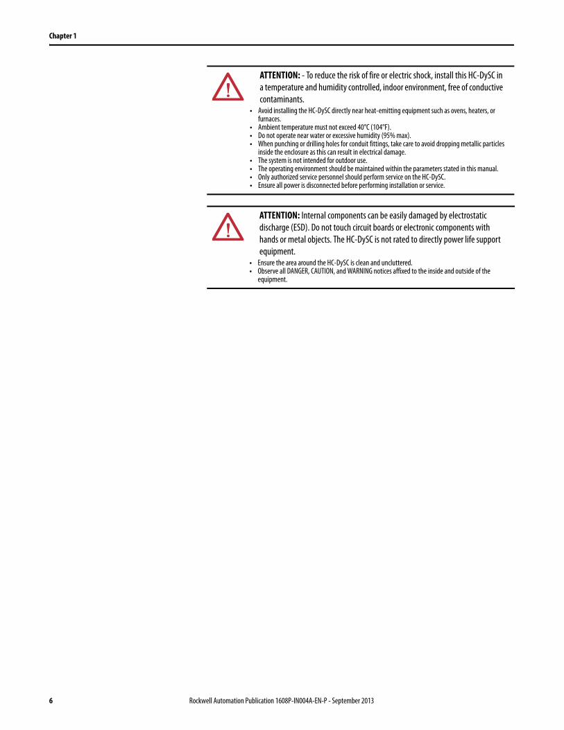
ATTENTION: - To reduce the risk of fire or electric shock, install this HC-DySC in a temperature and humidity controlled, indoor environment, free of conductive contaminants.
• Avoid installing the HC-DySC directly near heat-emitting equipment such as ovens, heaters, or furnaces.
• Ambient temperature must not exceed 40°C (104°F).• Do not operate near water or excessive humidity (95% max).• When punching or drilling holes for conduit fittings, take care to avoid dropping metallic particles
inside the enclosure as this can result in electrical damage.• The system is not intended for outdoor use.• The operating environment should be maintained within the parameters stated in this manual.• Only authorized service personnel should perform service on the HC-DySC.• Ensure all power is disconnected before performing installation or service.
ATTENTION: Internal components can be easily damaged by electrostatic discharge (ESD). Do not touch circuit boards or electronic components with hands or metal objects. The HC-DySC is not rated to directly power life support equipment.
• Ensure the area around the HC-DySC is clean and uncluttered. • Observe all DANGER, CAUTION, and WARNING notices affixed to the inside and outside of the
equipment.
6 Rockwell Automation Publication 1608P-IN004A-EN-P - September 2013
Chapter 2
Installation
Installation Check List Before proceeding, please take a few minutes to review the necessary steps to install your HC-DySC.
• All packing materials and restraints have been removed.• The HC-DySC is placed in its installed location.• All conduits and cables are properly routed to the HC-DySC.• All power cables are properly terminated.• A ground conductor is properly installed and terminated.• If neutral connection is required that it is properly terminated on the
HC-DySC.• The area around the installed HC-DySC is clean and dust-free.• Adequate work space exists around the HC-DySC.• Adequate lighting is provided around the HC-DySC.• Operational checks have been reviewed and completed.
Inspecting and Unpacking • Lift only at the base with a fork truck or pallet jack.• Carefully inspect the outer packaging for evidence of damage during
transit. Do not install a damaged cabinet. Report any damage to the carrier and contact your local sales or service immediately.
• Check the HC-DySC label for correct model number with the packaging list to ensure you have received the correct voltage, current, and wiring configurations.
• After removing the packaging material, inspect the contents for any evidence of physical damage, and compare each item with the Bill of Lading. If damage has occurred or shortages are evident contact your carrier immediately.
Location (Environment) The HC-DySC must be installed in a protected environment. The location must provide adequate airflow around the HC-DySC in an atmosphere free from excessive dust, corrosive fumes, or conductive contaminants. Do not operate the HC-DySC in an environment where the ambient temperature or humidity is beyond the specified limits given in this manual.
System Components The HC-DySC consists of a single enclosure with an integral mechanical bypass to prevent power disruption during service and maintenance.
Rockwell Automation Publication 1608P-UM004A-EN-P - September 2013 7
Chapter 2 Installation
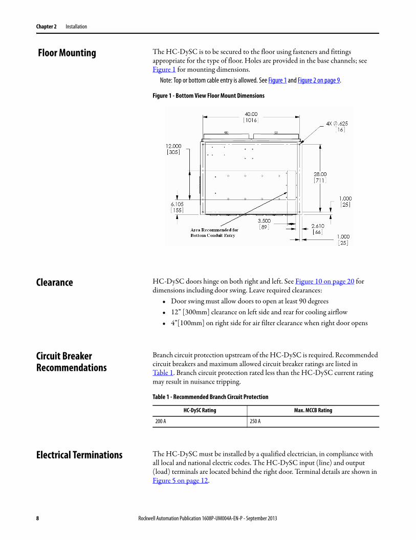
Floor Mounting The HC-DySC is to be secured to the floor using fasteners and fittings appropriate for the type of floor. Holes are provided in the base channels; see Figure 1 for mounting dimensions.
Note: Top or bottom cable entry is allowed. See Figure 1 and Figure 2 on page 9.
Figure 1 - Bottom View Floor Mount Dimensions
Clearance HC-DySC doors hinge on both right and left. See Figure 10 on page 20 for dimensions including door swing. Leave required clearances:
• Door swing must allow doors to open at least 90 degrees• 12” [300mm] clearance on left side and rear for cooling airflow• 4”[100mm] on right side for air filter clearance when right door opens
Circuit Breaker Recommendations
Branch circuit protection upstream of the HC-DySC is required. Recommended circuit breakers and maximum allowed circuit breaker ratings are listed in Table 1. Branch circuit protection rated less than the HC-DySC current rating may result in nuisance tripping.
Table 1 - Recommended Branch Circuit Protection
Electrical Terminations The HC-DySC must be installed by a qualified electrician, in compliance with all local and national electric codes. The HC-DySC input (line) and output (load) terminals are located behind the right door. Terminal details are shown in Figure 5 on page 12.
HC-DySC Rating Max. MCCB Rating
200 A 250 A
8 Rockwell Automation Publication 1608P-UM004A-EN-P - September 2013
Installation Chapter 2
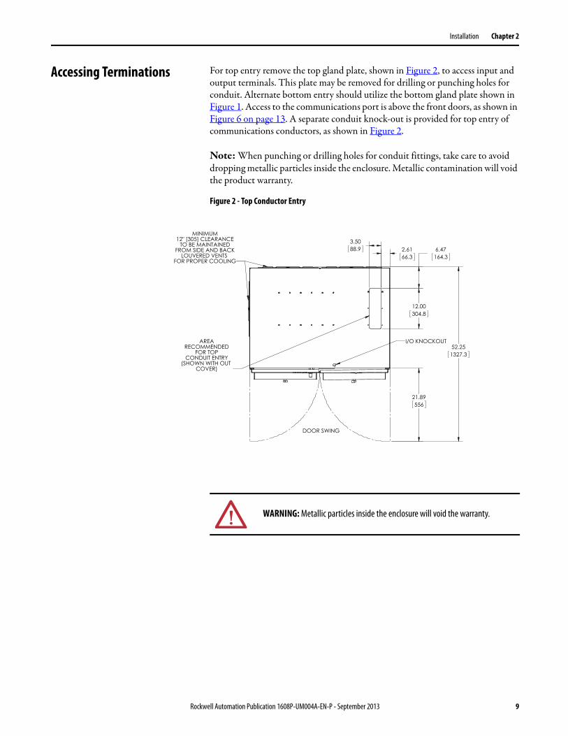
Accessing Terminations For top entry remove the top gland plate, shown in Figure 2, to access input and output terminals. This plate may be removed for drilling or punching holes for conduit. Alternate bottom entry should utilize the bottom gland plate shown in Figure 1. Access to the communications port is above the front doors, as shown in Figure 6 on page 13. A separate conduit knock-out is provided for top entry of communications conductors, as shown in Figure 2.
Note: When punching or drilling holes for conduit fittings, take care to avoid dropping metallic particles inside the enclosure. Metallic contamination will void the product warranty.
Figure 2 - Top Conductor Entry
WARNING: Metallic particles inside the enclosure will void the warranty.
Rockwell Automation Publication 1608P-UM004A-EN-P - September 2013 9
Chapter 2 Installation
3-Wire vs. 4-Wire Configurations
HC-DySC models are available for use with either 3-wire (L1, L2, L3) or 4-wire (L1, L2, L3, N) sources. The input N conductor must be connected to 4-wire models for proper operation. Do not connect a N conductor to 3-wire models.
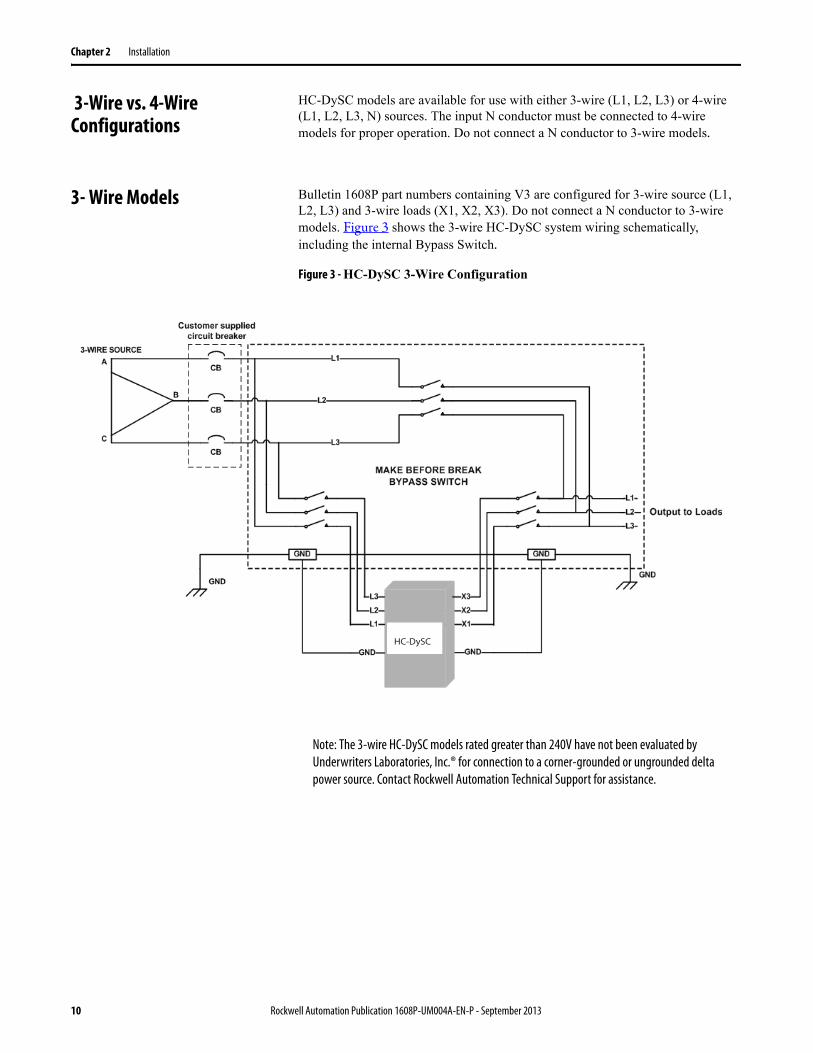
3- Wire Models Bulletin 1608P part numbers containing V3 are configured for 3-wire source (L1, L2, L3) and 3-wire loads (X1, X2, X3). Do not connect a N conductor to 3-wire models. Figure 3 shows the 3-wire HC-DySC system wiring schematically, including the internal Bypass Switch.
Figure 3 - HC-DySC 3-Wire Configuration
Note: The 3-wire HC-DySC models rated greater than 240V have not been evaluated by Underwriters Laboratories, Inc.® for connection to a corner-grounded or ungrounded delta power source. Contact Rockwell Automation Technical Support for assistance.
HC-DySC
10 Rockwell Automation Publication 1608P-UM004A-EN-P - September 2013
Installation Chapter 2
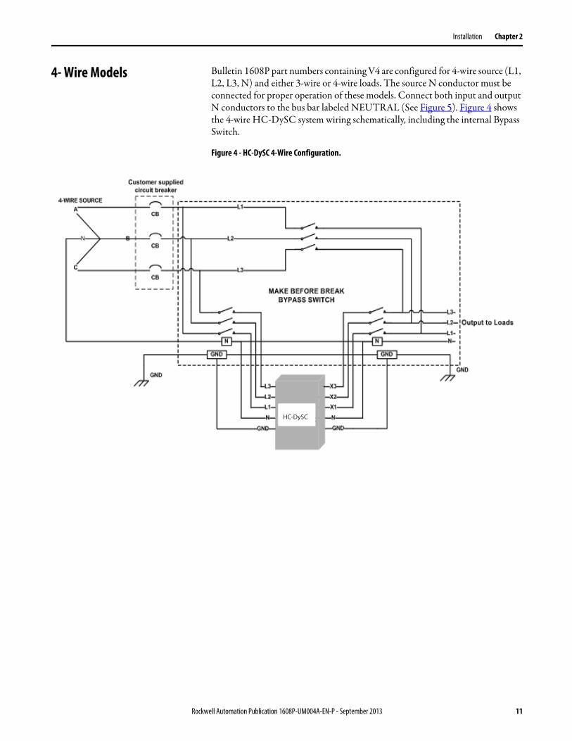
4- Wire Models Bulletin 1608P part numbers containing V4 are configured for 4-wire source (L1, L2, L3, N) and either 3-wire or 4-wire loads. The source N conductor must be connected for proper operation of these models. Connect both input and output N conductors to the bus bar labeled NEUTRAL (See Figure 5). Figure 4 shows the 4-wire HC-DySC system wiring schematically, including the internal Bypass Switch.
Figure 4 - HC-DySC 4-Wire Configuration.
HC-DySC
Rockwell Automation Publication 1608P-UM004A-EN-P - September 2013 11
Chapter 2 Installation
Electrical Terminations and Ratings
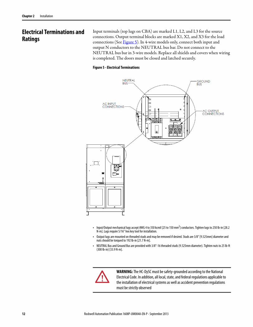
Input terminals (top lugs on CBA) are marked L1, L2, and L3 for the source connections. Output terminal blocks are marked X1, X2, and X3 for the load connections (See Figure 5). In 4-wire models only, connect both input and output N conductors to the NEUTRAL bus bar. Do not connect to the NEUTRAL bus bar in 3-wire models. Replace all shields and covers when wiring is completed. The doors must be closed and latched securely.
Figure 5 - Electrical Terminations
• Input/Output mechanical lugs accept AWG 4 to 350 kcmil [25 to 150 mm2] conductors. Tighten lugs to 250 lb-in [28.2 N-m]. Lugs require 5/16” hex key tool for installation.
• Output lugs are mounted on threaded studs and may be removed if desired. Studs are 3/8” [9.525mm] diameter and nuts should be torqued to 192 lb-in [21.7 N-m].
• NEUTRAL Bus and Ground Bus are provided with 3/8”-16 threaded studs (9.525mm diameter). Tighten nuts to 25 lb-ft (300 lb-in) [33.9 N-m].
WARNING: The HC-DySC must be safety-grounded according to the National Electrical Code. In addition, all local, state, and federal regulations applicable to the installation of electrical systems as well as accident prevention regulations must be strictly observed
12 Rockwell Automation Publication 1608P-UM004A-EN-P - September 2013
Chapter 3
Communications
Both dry contacts (relays) that indicate status and a Serial Communications Port (RS-232) are available for monitoring the HC-DySC.
Dry Contacts Three relay contacts indicate HC-DySC status. The contacts are form A and close upon occurrence of the named event: (a) any SAG EVENT, when rms input voltage drops below 88.5% of rated value; (b) OUTPUT OK, when output voltage remains between 87% and 110%; and (c) a system ALARM event. The relay contact ratings are 24V at 1A.
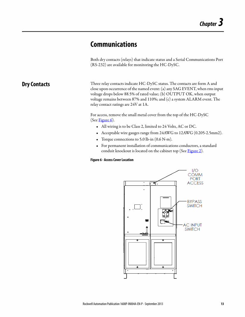
For access, remove the small metal cover from the top of the HC-DySC (See Figure 6).
• All wiring is to be Class 2, limited to 24 Volts, AC or DC. • Acceptable wire gauges range from 24AWG to 12AWG (0.205-2.5mm2). • Torque connections to 5.0 lb-in (0.6 N-m).• For permanent installation of communications conductors, a standard
conduit knockout is located on the cabinet top (See Figure 2).
Figure 6 - Access Cover Location
Rockwell Automation Publication 1608P-IN004A-EN-P - September 2013 13
Chapter 3 Communications
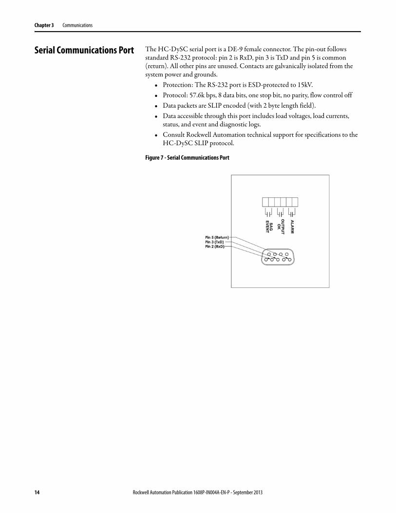
Serial Communications Port The HC-DySC serial port is a DE-9 female connector. The pin-out follows standard RS-232 protocol: pin 2 is RxD, pin 3 is TxD and pin 5 is common (return). All other pins are unused. Contacts are galvanically isolated from the system power and grounds.
• Protection: The RS-232 port is ESD-protected to 15kV.• Protocol: 57.6k bps, 8 data bits, one stop bit, no parity, flow control off• Data packets are SLIP encoded (with 2 byte length field).• Data accessible through this port includes load voltages, load currents,
status, and event and diagnostic logs.• Consult Rockwell Automation technical support for specifications to the
HC-DySC SLIP protocol.
Figure 7 - Serial Communications Port
14 Rockwell Automation Publication 1608P-IN004A-EN-P - September 2013
Chapter 4
Applying Power and Operation
Applying Power • Before applying power to the HC-DySC, make certain there are no metal filings or any conductive debris in or on any components inside the cabinet.
• Verify HC-DySC voltage rating matches ac source voltage.• Ensure all input/output wiring including grounding has been completed
and properly tightened.• Verify CBA circuit breaker is in the ON position before replacing covers.
Replace all covers. Close and lock cabinet doors.• Put bypass switch in the “BYPASS” position.• Put CBI circuit breaker in the ON position.• Apply power from the upstream branch protection device. Power will flow
directly to the load through the bypass switch. The HC-DySC touchscreen will become active and display “System Offline” in the upper left corner.
• Verify output (load) voltage is present• Put bypass switch in the “TEST” position. The HC-DySC system will
become energized in this mode but the load will still be powered through the bypass switch.
• Ensure that the touchscreen displays “OK” in the upper left corner, with a bar above that states “Sag Prot. Bypassed.” Ensure that the voltage, current, and frequency readings in the status display are correct.
• If a “Critical” or “Fatal” system event appears on the touch screen (1) place the maintenance bypass switch in BYPASS and (2) call for technical support.
• Put the bypass switch in the “NORMAL” position. The load is now being protected by the HC-DySC. The display should show “OK” in the upper left corner.
NOTICE: Cycling HC-DySC input power in the sequence OFF--ON--OFF--ON within a one minuteperiod will cause a “Limit Cycle Timeout” alarm. In such case sag correction will be inhibited forone minute, after which the alarm will automatically reset.
WARNING: This system is interlocked: Opening HC-DySC doors while the system is in operation will result in loss of power to protected loads, unless the bypass switch is in the Bypass mode (see HC-DySC SYSTEM OPERATION)
Rockwell Automation Publication 1608P-IN004A-EN-P - September 2013 15
Chapter 4 Applying Power and Operation
HC-DySC System Operation
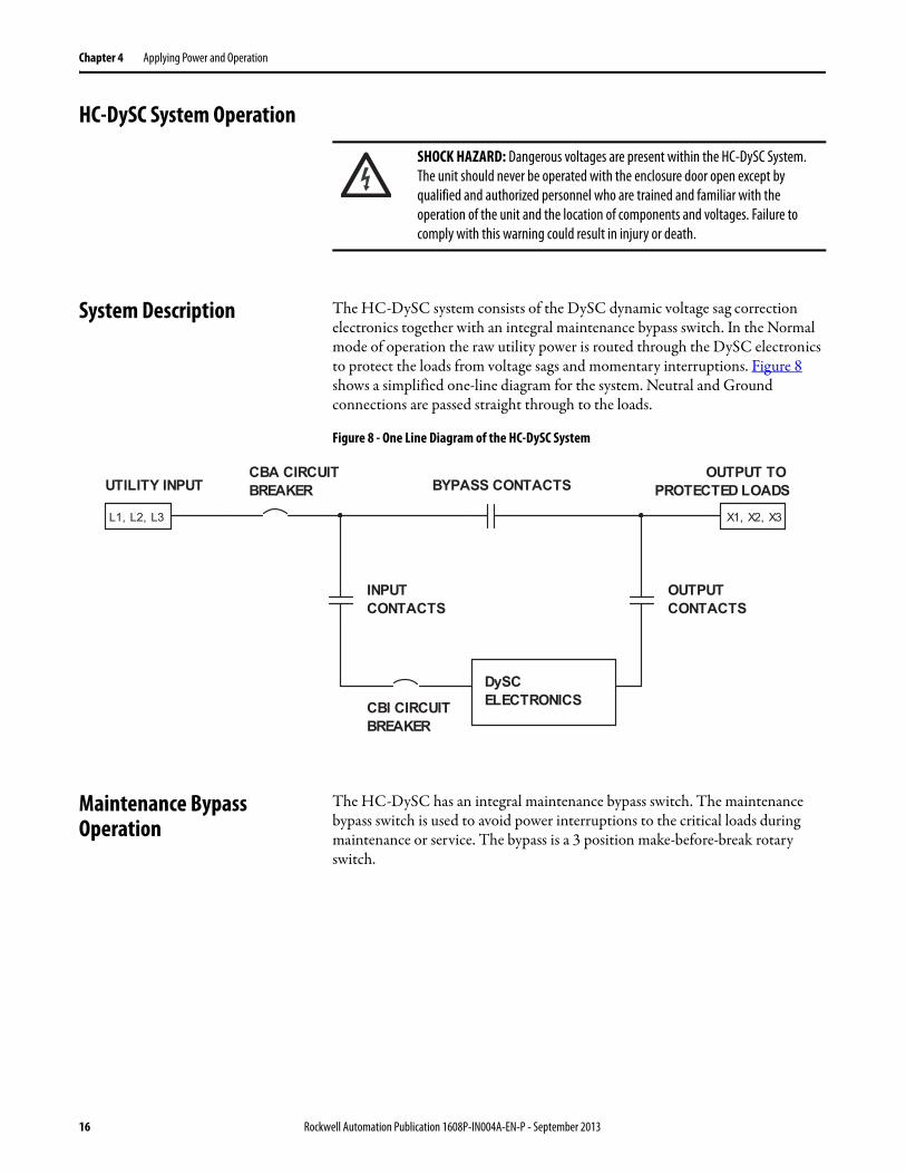
System Description The HC-DySC system consists of the DySC dynamic voltage sag correction electronics together with an integral maintenance bypass switch. In the Normal mode of operation the raw utility power is routed through the DySC electronics to protect the loads from voltage sags and momentary interruptions. Figure 8 shows a simplified one-line diagram for the system. Neutral and Ground connections are passed straight through to the loads.
Figure 8 - One Line Diagram of the HC-DySC System
Maintenance Bypass Operation
The HC-DySC has an integral maintenance bypass switch. The maintenance bypass switch is used to avoid power interruptions to the critical loads during maintenance or service. The bypass is a 3 position make-before-break rotary switch.
SHOCK HAZARD: Dangerous voltages are present within the HC-DySC System. The unit should never be operated with the enclosure door open except by qualified and authorized personnel who are trained and familiar with the operation of the unit and the location of components and voltages. Failure to comply with this warning could result in injury or death.
L1, L2, L3 X1, X2, X3
DySCELECTRONICS
OUTPUT TOPROTECTED LOADS
CBI CIRCUITBREAKER
OUTPUTCONTACTS
INPUTCONTACTS
BYPASS CONTACTSUTILITY INPUTCBA CIRCUITBREAKER
16 Rockwell Automation Publication 1608P-IN004A-EN-P - September 2013
Applying Power and Operation Chapter 4
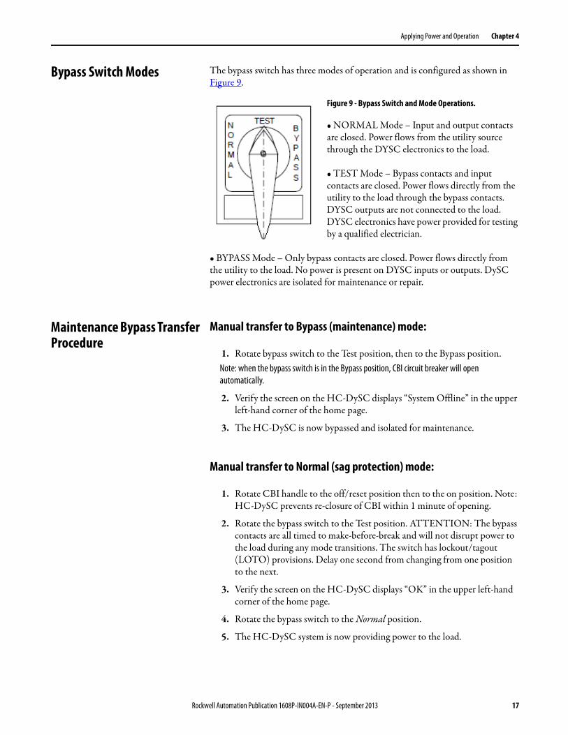
Bypass Switch Modes The bypass switch has three modes of operation and is configured as shown in Figure 9.
Figure 9 - Bypass Switch and Mode Operations.
• NORMAL Mode – Input and output contacts are closed. Power flows from the utility source through the DYSC electronics to the load.
• TEST Mode – Bypass contacts and input contacts are closed. Power flows directly from the utility to the load through the bypass contacts. DYSC outputs are not connected to the load. DYSC electronics have power provided for testing by a qualified electrician.
• BYPASS Mode – Only bypass contacts are closed. Power flows directly from the utility to the load. No power is present on DYSC inputs or outputs. DySC power electronics are isolated for maintenance or repair.
Maintenance Bypass Transfer Procedure
Manual transfer to Bypass (maintenance) mode:
1. Rotate bypass switch to the Test position, then to the Bypass position.Note: when the bypass switch is in the Bypass position, CBI circuit breaker will open automatically.
2. Verify the screen on the HC-DySC displays “System Offline” in the upper left-hand corner of the home page.
3. The HC-DySC is now bypassed and isolated for maintenance.
Manual transfer to Normal (sag protection) mode:
1. Rotate CBI handle to the off/reset position then to the on position. Note: HC-DySC prevents re-closure of CBI within 1 minute of opening.
2. Rotate the bypass switch to the Test position. ATTENTION: The bypass contacts are all timed to make-before-break and will not disrupt power to the load during any mode transitions. The switch has lockout/tagout (LOTO) provisions. Delay one second from changing from one position to the next.
3. Verify the screen on the HC-DySC displays “OK” in the upper left-hand corner of the home page.
4. Rotate the bypass switch to the Normal position.
5. The HC-DySC system is now providing power to the load.
Rockwell Automation Publication 1608P-IN004A-EN-P - September 2013 17
Chapter 4 Applying Power and Operation
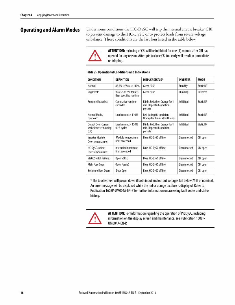
Operating and Alarm Modes Under some conditions the HC-DySC will trip the internal circuit breaker CBI to prevent damage to the HC-DySC or to protect loads from severe voltage unbalance. Those conditions are the last four listed in the table below.
Table 2 - Operational Conditions and Indications
* The touchscreen will power down if both input and output voltages fall below 75% of nominal. An error message will be displayed while the red or orange text box is displayed. Refer to Publication 1608P-UM004A-EN-P for further information on accessing fault codes and status history.
ATTENTION: reclosing of CBI will be inhibited for one (1) minute after CBI has opened for any reason. Attempts to close CBI too early will result in immediate re-tripping.
CONDITION DEFINITION DISPLAY STATUS* INVERTER MODE
Normal: 88.5% < V LINE < 110% Green “OK” Standby Static BP
Sag Event: V LINE < 88.5% for less than specified runtime
Green “OK” Running Inverter
Runtime Exceeded: Cumulative runtime exceeded
Blinks Red, then Orange for 1 min. Repeats if condition persists
Inhibited Static BP
Normal Mode, Overload:
Load current > 110% Red during OL condition, Orange for 1 min. after OL ends
Inhibited Static BP
Output Over-Current while inverter running (I2t)
Load current > 150% for 3 cycles
Blinks Red, then Orange for 1 min. Repeats if condition persists
Inhibited Static BP
Inverter Module Over-temperature:
Module temperature limit exceeded
Blue, HC-DySC offline Disconnected CBI open
HC-DySC cabinet Over-temperature:
Internal temperature limit exceeded
Blue, HC-DySC offline Disconnected CBI open
Static Switch Failure: Open SCR(s) Blue, HC-DySC offline Disconnected CBI open
Main Fuse Open Open Fuse(s) Blue, HC-DySC offline Disconnected CBI open
Enclosure Door Open: Door Open Blue, HC-DySC offline Disconnected CBI open
ATTENTION: For Information regarding the operation of ProDySC, including information on the display screen and maintenance, see Publication 1608P-UM004A-EN-P.
18 Rockwell Automation Publication 1608P-IN004A-EN-P - September 2013
Rockwell Automation Publication 1608P-IN004A-EN-P - September 2013 19
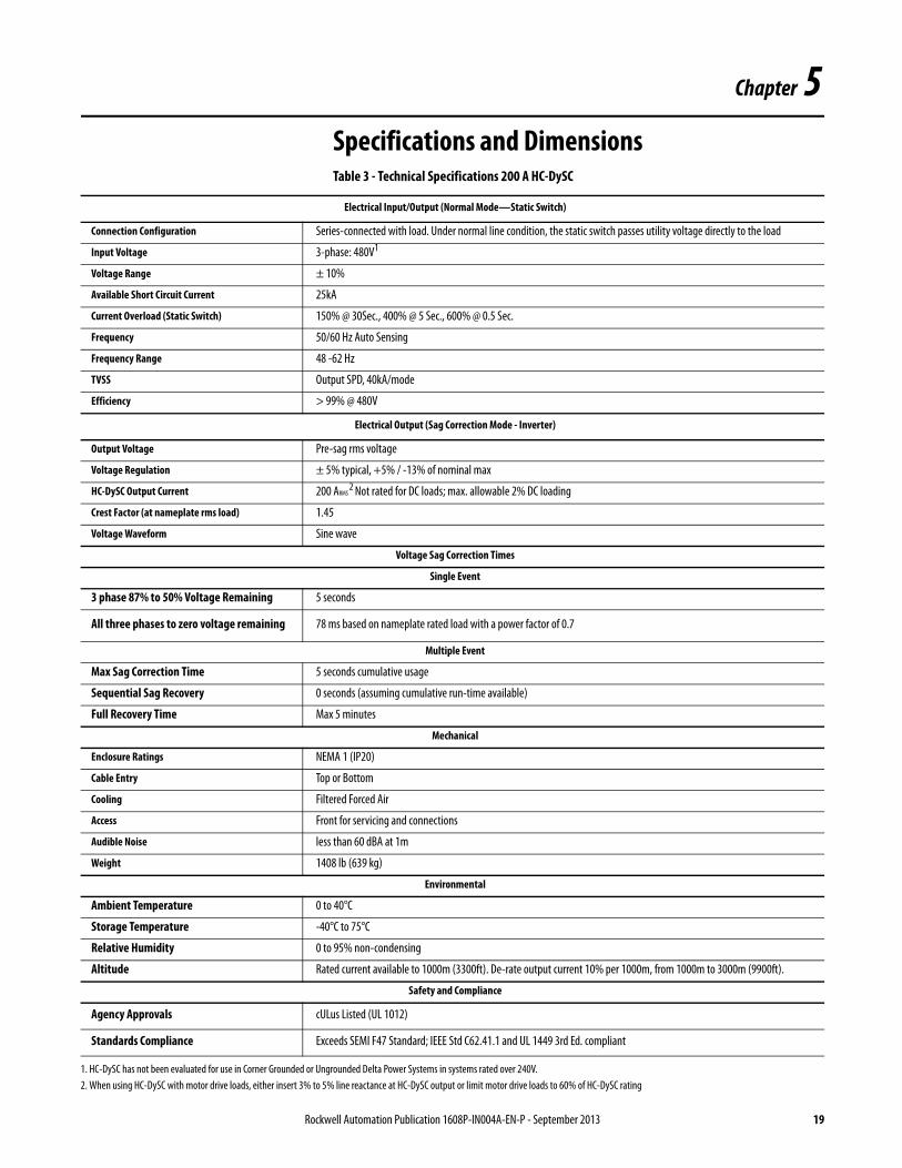
Chapter 5Specifications and Dimensions Table 3 - Technical Specifications 200 A HC-DySC
Electrical Input/Output (Normal Mode—Static Switch)
Connection Configuration Series-connected with load. Under normal line condition, the static switch passes utility voltage directly to the load
Input Voltage 3-phase: 480V1
Voltage Range ± 10%
Available Short Circuit Current 25kA
Current Overload (Static Switch) 150% @ 30Sec., 400% @ 5 Sec., 600% @ 0.5 Sec.
Frequency 50/60 Hz Auto Sensing
Frequency Range 48 -62 Hz
TVSS Output SPD, 40kA/mode
Efficiency > 99% @ 480V
Electrical Output (Sag Correction Mode - Inverter)
Output Voltage Pre-sag rms voltage
Voltage Regulation ± 5% typical, +5% / -13% of nominal max
HC-DySC Output Current 200 ARMS 2 Not rated for DC loads; max. allowable 2% DC loading
Crest Factor (at nameplate rms load) 1.45
Voltage Waveform Sine wave
Voltage Sag Correction Times
Single Event
3 phase 87% to 50% Voltage Remaining 5 seconds
All three phases to zero voltage remaining 78 ms based on nameplate rated load with a power factor of 0.7
Multiple Event
Max Sag Correction Time 5 seconds cumulative usage
Sequential Sag Recovery 0 seconds (assuming cumulative run-time available)
Full Recovery Time Max 5 minutes
Mechanical
Enclosure Ratings NEMA 1 (IP20)
Cable Entry Top or Bottom
Cooling Filtered Forced Air
Access Front for servicing and connections
Audible Noise less than 60 dBA at 1m
Weight 1408 lb (639 kg)
Environmental
Ambient Temperature 0 to 40°C
Storage Temperature -40°C to 75°C
Relative Humidity 0 to 95% non-condensing
Altitude Rated current available to 1000m (3300ft). De-rate output current 10% per 1000m, from 1000m to 3000m (9900ft).
Safety and Compliance
Agency Approvals cULus Listed (UL 1012)
Standards Compliance Exceeds SEMI F47 Standard; IEEE Std C62.41.1 and UL 1449 3rd Ed. compliant
1. HC-DySC has not been evaluated for use in Corner Grounded or Ungrounded Delta Power Systems in systems rated over 240V.2. When using HC-DySC with motor drive loads, either insert 3% to 5% line reactance at HC-DySC output or limit motor drive loads to 60% of HC-DySC rating
Chapter 5 Specifications and Dimensions
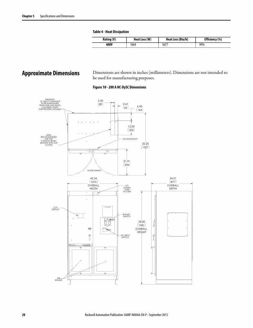
Table 4 - Heat Dissipation
Approximate Dimensions Dimensions are shown in inches (millimeters). Dimensions are not intended to be used for manufacturing purposes.
Figure 10 - 200 A HC-DySC Dimensions
Rating (V) Heat Loss (W) Heat Loss (Btu/h) Efficiency (%)480V 1664 5677 99%
20 Rockwell Automation Publication 1608P-IN004A-EN-P - September 2013

Publication 1608P-IN004A-EN-P - September 2013 Copyright © 2013 Rockwell Automation, Inc. All rights reserved. Printed in the U.S.ADIR 10000820213
Rockwell Automation Support
Rockwell Automation provides technical information on the Web to assist you in using its products. At http://www.rockwellautomation.com/support, you can find technical manuals, technical and application notes, sample code and links to software service packs, and a MySupport feature that you can customize to make the best use of these tools. You can also visit our Knowledgebase at http://www.rockwellautomation.com/knowledgebase for FAQs, technical information, support chat and forums, software updates, and to sign up for product notification updates.
For an additional level of technical phone support for installation, configuration, and troubleshooting, we offer TechConnectSM support programs. For more information, contact your local distributor or Rockwell Automation representative, or visit http://www.rockwellautomation.com/support/.
Installation Assistance
If you experience a problem within the first 24 hours of installation, review the information that is contained in this manual. You can contact Customer Support for initial help in getting your product up and running.
New Product Satisfaction Return
Rockwell Automation tests all of its products to help ensure that they are fully operational when shipped from the manufacturing facility. However, if your product is not functioning and needs to be returned, follow these procedures.
Documentation Feedback
Your comments will help us serve your documentation needs better. If you have any suggestions on how to improve this document, complete this form, publication RA-DU002, available at http://www.rockwellautomation.com/literature/.
United States or Canada 1.440.646.3434
Outside United States or Canada Use the Worldwide Locator at http://www.rockwellautomation.com/rockwellautomation/support/overview.page, or contact your local Rockwell Automation representative.
United States Contact your distributor. You must provide a Customer Support case number (call the phone number above to obtain one) to your distributor to complete the return process.
Outside United States Please contact your local Rockwell Automation representative for the return procedure.


![[Mesh] Inspecting for Hazardous](https://img.pdfslide.us/doc/110x75/5695d02a1a28ab9b029144f9/mesh-inspecting-for-hazardous.jpg)