Embed Size (px)
Citation preview

NH-4 HeatersCustomer Product Manual
Document Number � 1602369-04Issued 09/21
For parts and technical support, call the Industrial Coating Systems Customer Support Center at (800) 433-9319 or
contact your local Nordson representative.
This document is subject to change without notice.Check http://emanuals.nordson.com for the latest version.
NORDSON CORPORATION • AMHERST, OHIO • USA

© 2021 Nordson Corporation1602369-04
Contact UsNordson Corporation welcomes requests for information, comments, and inquiries about its products. General information about Nordson can be found on the Internet using the following address:http://www.nordson.com.Address all correspondence to:
Nordson CorporationAttn: Customer Service555 Jackson StreetAmherst, OH 44001
NoticeThis is a Nordson Corporation publication which is protected by copyright.Original copyright date 2013. No part of this document may be photocopied, reproduced, or translated to another language without the prior written consent of Nordson Corporation. The information contained in this publication is subject to change without notice.TrademarksNordson and the Nordson logo are registered trademarks of Nordson Corporation. All other trademarks are the property of their respective owners.
Table of ContentsSafety ............................................................................................................................................... 1Introduction ...................................................................................................................................... 1Qualified Personnel ......................................................................................................................... 1Intended Use ................................................................................................................................... 1Regulations and Approvals .............................................................................................................. 1Personal Safety ............................................................................................................................... 2High-Pressure Fluids ...................................................................................................................... 3
Fire Safety ....................................................................................................................................... 4Halogenated Hydrocarbon Solvent Hazards .................................................................................. 4
Action in the Event of a Malfunction ................................................................................................ 5Disposal ........................................................................................................................................... 5
Description ...................................................................................................................................... 6Theory of Operation ......................................................................................................................... 7Identifying Groups of Heaters .......................................................................................................... 7NH-4 Heater Versions ...................................................................................................................... 8
Installation ....................................................................................................................................... 8Location and Mounting .................................................................................................................... 8Electrical .......................................................................................................................................... 9Fluid Lines and Fittings.................................................................................................................. 10Multiple Heater Installations ...........................................................................................................11Thermometer Installation ............................................................................................................... 12Filter Installation ............................................................................................................................ 13Thermostat Adjustment — Single Heater Installation .................................................................... 13Thermostat Adjustment — Multiple Heater Installations ................................................................ 13
Operation ....................................................................................................................................... 14Safety Precautions ........................................................................................................................ 14Startup ........................................................................................................................................... 14Thermostat Adjustments ................................................................................................................ 15Shutdown ....................................................................................................................................... 15Daily Maintenance ......................................................................................................................... 16
Troubleshooting ............................................................................................................................ 17Repair ............................................................................................................................................. 18Thermostat Replacement .............................................................................................................. 18Thermostat Removal .................................................................................................................... 18Thermostat Installation ................................................................................................................. 18
Heat Limiter Replacement ............................................................................................................. 20Heater Cartridge Replacement ...................................................................................................... 20Fluid Heating Reservoir Replacement ........................................................................................... 20Fluid Heating Reservoir Removal ................................................................................................. 21High Pressure Housing Removal − Standard Heaters Only ........................................................ 22Fluid Heating Reservoir Installation.............................................................................................. 22

© 2021 Nordson Corporation 1602369-04
Parts ............................................................................................................................................... 23Heater Reference Chart ................................................................................................................ 23Standard NH-4 Heaters ................................................................................................................. 24115 Volt: Single Passage — 1700 watts ....................................................................................... 24115 Volt: Twin Passage — 500 watts ........................................................................................... 26115 Volt: Twin Passage — 1000 watts ......................................................................................... 28200 Volt: Single and Twin Passage — 1700 watt ......................................................................... 30200 Volt: Single Passage — Japan Only — 1700 watt ................................................................ 32200 Volt: Twin Passage — Japan Only — 1700 watt ................................................................... 34230 Volt: Single Passage — 1700 watt ........................................................................................ 36230 Volt: Twin Passage — 1000 watt ........................................................................................... 38230 Volt: Twin Passage — 1700 watt ........................................................................................... 40380 Volt: Single Passage and Twin Passage — 1700 watt .......................................................... 42460 Volt: Single and Twin Passage — 1700 watt ......................................................................... 46
Stainless Steel NH-4 Heaters ........................................................................................................ 48115 Volt: Single Passage — 1700 watt ........................................................................................ 48230 Volt: Single Passage — 1700 watt ........................................................................................ 50380 Volt: Single Passage — 1700 watt ........................................................................................ 52460 Volt: Single Passage − 1700 watt .......................................................................................... 54200 Volt: Single Passage — Japan Only — 1700 watt ................................................................ 56
Kits and Spare Parts ...................................................................................................................... 57Standard NH-4 Thermostat/Heat Limiter Kit ................................................................................. 57Standard NH-4 Thermostat Kit ..................................................................................................... 57Stainless Steel NH-4 Thermostat/Heat Limiter Kit ....................................................................... 57External Adjust Kit ........................................................................................................................ 58Manual Reset Thermostat Kit — Japan Only ............................................................................... 58Standard NH-4 Single Passage Fluid Reservoir Seal Kit ............................................................. 58Standard NH-4 Twin Passage Fluid Reservoir Seal Kit ............................................................... 58Stainless Steel Alternate Fitting.................................................................................................... 58Heater Cartridges (Standard and Stainless Steel Heaters).......................................................... 59
Recommended Spare Parts .......................................................................................................... 59

© 2021 Nordson Corporation1602369-04
iChange Record
© 2021 Nordson Corporation 1602369-04
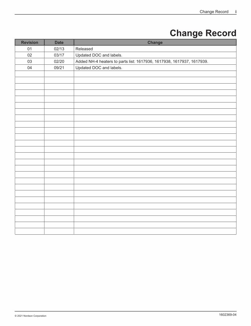
Change RecordRevision Date Change
01 02/13 Released02 03/17 Updated DOC and labels.03 02/20 Added NH-4 heaters to parts list: 1617936, 1617938, 1617937, 1617939.04 09/21 Updated DOC and labels.

© 2021 Nordson Corporation1602369-04
ii Change Record
1NH-4 Heaters
© 2021 Nordson Corporation 1602369-04
SafetyIntroduction
Read and follow these safety instructions. Task- and equipment-specific warnings, cautions, and instructions are included in equipment documentation where appropriate.
Make sure all equipment documentation, including these instructions, is accessible to persons operating or servicing equipment.
Qualified PersonnelEquipment owners are responsible for making sure that Nordson equipment is installed, operated, and serviced by qualified personnel. Qualified personnel are those employees or contractors who are trained to safely perform their assigned tasks. They are familiar with all relevant safety rules and regulations and are physically capable of performing their assigned tasks.
Intended UseUse of Nordson equipment in ways other than those described in the documentation supplied with the equipment may result in injury to persons or damage to property.
Some examples of unintended use of equipment include:
• using incompatible materials
• making unauthorized modifications
• removing or bypassing safety guards or interlocks
• using incompatible or damaged parts
• using unapproved auxiliary equipment
• operating equipment in excess of maximum ratings
Regulations and ApprovalsMake sure all equipment is rated and approved for the environment in which it is used. Any approvals obtained for Nordson equipment will be voided if instructions for installation, operation, and service are not followed.
2 NH-4 Heaters
© 2021 Nordson Corporation1602369-04
Personal SafetyTo prevent injury follow these instructions.
• Do not operate or service equipment unless you are qualified.
• Do not operate equipment unless safety guards, doors, or covers are intact and automatic interlocks are operating properly. Do not bypass or disarm any safety devices.
• Keep clear of moving equipment. Before adjusting or servicing moving equipment, shut off the power supply and wait until the equipment comes to a complete stop. Lock out power and secure the equipment to prevent unexpected movement.
• Relieve (bleed off) hydraulic and pneumatic pressure before adjusting or servicing pressurized systems or components. Disconnect, lock out, and tag switches before servicing electrical equipment.
• While operating manual spray guns, make sure you are grounded. Wear electrically conductive gloves or a grounding strap connected to the gun handle or other true earth ground. Do not wear or carry metallic objects such as jewelry or tools.
• If you receive even a slight electrical shock, shut down all electrical or electrostatic equipment immediately. Do not restart the equipment until the problem has been identified and corrected.
• Obtain and read Safety Data Sheets (SDS) for all materials used. Follow the manufacturer’s instructions for safe handling and use of materials, and use recommended personal protection devices.
• Make sure the spray area is adequately ventilated. To prevent injury, be aware of less-obvious dangers in the workplace that often cannot be completely eliminated, such as hot surfaces, sharp edges, energized electrical circuits, and moving parts that cannot be enclosed or otherwise guarded for practical reasons.
3NH-4 Heaters
© 2021 Nordson Corporation 1602369-04
High-Pressure FluidsHigh-pressure fluids, unless they are safely contained, are extremely hazardous. Always relieve fluid pressure before adjusting or servicing high pressure equipment. A jet of high-pressure fluid can cut like a knife and cause serious bodily injury, amputation, or death. Fluids penetrating the skin can also cause toxic poisoning.
If you suffer a fluid injection injury, seek medical care immediately. If possible, provide a copy of the SDS for the injected fluid to the health care provider.
The National Spray Equipment Manufacturers Association has created a wallet card that you should carry when you are operating high-pressure spray equipment. These cards are supplied with your equipment. The following is the text of this card:
WARNING: � Any injury caused by high pressure liquid can be serious. If you are injured or even suspect an injury:
• Go to an emergency room immediately.
• Tell the doctor that you suspect an injection injury.
• Show them this card
• Tell them what kind of material you were spraying
MEDICAL ALERT — AIRLESS SPRAY WOUNDS: NOTE TO PHYSICIAN
Injection in the skin is a serious traumatic injury. It is important to treat the injury surgically as soon as possible. Do not delay treatment to research toxicity. Toxicity is a concern with some exotic coatings injected directly into the bloodstream.
Consultation with a plastic surgeon or a reconstructive hand surgeon may be advisable.
The seriousness of the wound depends on where the injury is on the body, whether the substance hit something on its way in and deflected causing more damage, and many other variables including skin microflora residing in the paint or gun which are blasted into the wound. If the injected paint contains acrylic latex and titanium dioxide that damage the tissue’s resistance to infection, bacterial growth will flourish. The treatment that doctors recommend for an injection injury to the hand includes immediate decompression of the closed vascular compartments of the hand to release the underlying tissue distended by the injected paint, judicious wound debridement, and immediate antibiotic treatment.

4 NH-4 Heaters
© 2021 Nordson Corporation1602369-04
Fire SafetyTo avoid a fire or explosion, follow these instructions.
• Ground all conductive equipment. Use only grounded air and fluid hoses. Check equipment and workpiece grounding devices regularly. Resistance to ground must not exceed one megohm.
• Shut down all equipment immediately if you notice static sparking or arcing. Do not restart the equipment until the cause has been identified and corrected.
• Do not smoke, weld, grind, or use open flames where flammable materials are being used or stored. Do not heat materials to temperatures above those recommended by the manufacturer. Make sure heat monitoring and limiting devices are working properly.
• Provide adequate ventilation to prevent dangerous concentrations of volatile particles or vapors. Refer to local codes or your material SDS for guidance.
• Do not disconnect live electrical circuits when working with flammable materials. Shut off power at a disconnect switch first to prevent sparking.
• Know where emergency stop buttons, shutoff valves, and fire extinguishers are located. If a fire starts in a spray booth, immediately shut off the spray system and exhaust fans.
• Shut off electrostatic power and ground the charging system before adjusting, cleaning, or repairing electrostatic equipment.
• Clean, maintain, test, and repair equipment according to the instructions in your equipment documentation.
• Use only replacement parts that are designed for use with original equipment. Contact your Nordson representative for parts information and advice.
Halogenated Hydrocarbon Solvent HazardsDo not use halogenated hydrocarbon solvents in a pressurized system that contains aluminum components. Under pressure, these solvents can react with aluminum and explode, causing injury, death, or property damage. Halogenated hydrocarbon solvents contain one or more of the following elements:
Element Symbol PrefixFluorine F “Fluoro-”Chlorine Cl “Chloro-”Bromine Br “Bromo-”Iodine I “Iodo-”
Check your material SDS or contact your material supplier for more information. If you must use halogenated hydrocarbon solvents, contact your Nordson representative for information about compatible Nordson components.

5NH-4 Heaters
© 2021 Nordson Corporation 1602369-04
Action in the Event of a MalfunctionIf a system or any equipment in a system malfunctions, shut off the system immediately and perform the following steps:
• Disconnect and lock out system electrical power. Close hydraulic and pneumatic shutoff valves and relieve pressures.
• Identify the reason for the malfunction and correct it before restarting the system.
DisposalDispose of equipment and materials used in operation and servicing according to local codes.
6 NH-4 Heaters
© 2021 Nordson Corporation1602369-04
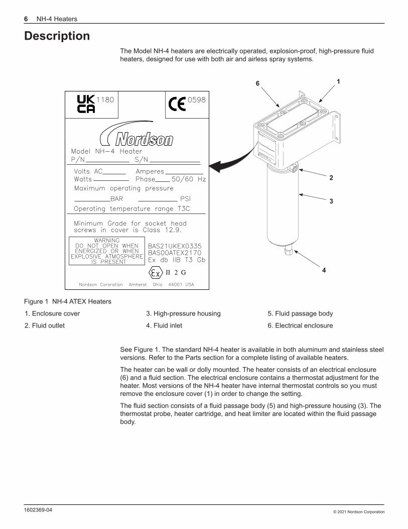
DescriptionThe Model NH-4 heaters are electrically operated, explosion-proof, high-pressure fluid heaters, designed for use with both air and airless spray systems.
Model NH-4 HeaterP/N S/N
Volts ACWatts
AmperesPhase
PSIBAR
Nordson Cororation Amherst Ohio 44001 USA
G
0598
BAS00ATEX2170
WARNING DO NOT OPEN WHEN ENERGIZED OR WHEN
EXPLOSIVE ATMOSPHERE IS PRESENT
BAS21UKEX0335
1180
6 1
2
3
4
Figure 1 NH-4 ATEX Heaters
1. Enclosure cover
2. Fluid outlet
3. High-pressure housing
4. Fluid inlet
5. Fluid passage body
6. Electrical enclosure
See Figure 1. The standard NH-4 heater is available in both aluminum and stainless steel versions. Refer to the Parts section for a complete listing of available heaters.
The heater can be wall or dolly mounted. The heater consists of an electrical enclosure (6) and a fluid section. The electrical enclosure contains a thermostat adjustment for the heater. Most versions of the NH-4 heater have internal thermostat controls so you must remove the enclosure cover (1) in order to change the setting.
The fluid section consists of a fluid passage body (5) and high-pressure housing (3). The thermostat probe, heater cartridge, and heat limiter are located within the fluid passage body.

7NH-4 Heaters
© 2021 Nordson Corporation 1602369-04
Theory of OperationSee Figure 2. The heater cartridge heats the fluid passage body (6). Coating material flows through the inlet port (4) and the spiral passages in the fluid passage body where it is heated then exits through the outlet port (8).
An adjustable thermostat (7) controls the temperature. If the thermostat fails, causing an over-temperature condition, the heat limiter (1) will sense the excess heat and open the circuit to the heater cartridge, shutting down the heater.
8
7
6
5
4
1
2
3
Figure 2 Cutaway View of Heater Components
1. Heat limiter
2. Spiral grooves
3. Heater cartridge
4. Inlet port
5. High-pressure housing
6. Fluid passage body
7. Thermostat
8. Outlet port
Identifying Groups of HeatersThis manual covers different types of NH-4 heaters. When procedures or data differs, the following codes will be used:
[EXT ADJ]—This code is used for NH-4 heaters that have an external adjustable thermostat control.
[INT ADJ]—This code is used for NH-4 heaters that have an internal adjustable thermostat control.
[ST STL]—This code is used for stainless steel NH-4 heaters.
8 NH-4 Heaters
© 2021 Nordson Corporation1602369-04
NH-4 Heater VersionsRefer to the Parts section for descriptions, specifications, and part numbers of available NH-4 heaters.
InstallationWARNING: � Allow only qualified personnel to perform the following tasks. Follow the safety instructions in this document and all other related documentation.
WARNING: � All EX approved heaters have a torque specification for the enclosure cover bolts of 1.11−1.66 kg•m (8−12 ft-lbs). Before installing the cover make sure it and the top of the enclosure are clean and free of dirt and debris. Use only bolts of the grade speci-fied on the equipment label. Tighten the bolts to the torque specification.
WARNING: � The purchaser should make the manufacturer aware of the external effects or aggressive substances that the equipment may be exposed to.
Location and MountingWARNING: � Installation must be performed by a qualified electrician and conform to all federal, state and local codes.
See Figure 3.
Mount the NH-4 heater in a vertical position on a wall or panel, allowing adequate surrounding space to perform periodic maintenance. Always locate the heater as close to the spray operation as possible.
NOTE: � All ATEX approved NH-4 heaters include a kit with several labels in different languages. Choose and install the appropriate language label for your NH-4 heater.

9NH-4 Heaters
© 2021 Nordson Corporation 1602369-04
232 mm (9.13 in.)
57 mm (2.25 in.)
41.5 mm (1.63 in.)
149 mm (5.866 in.)
Outlet Single passage
3/8 NPTF
Twin passage 1/2 NPTF
3/4 NPT Both sides
4 Holes ø9.5 mm
(ø0.374 in.)
84 mm (3.307 in.)
433 mm (17.86 in.)
Single passage 3/8 NPTF
Twin passage 1/2 NPTF
Inlet
98 mm (3.54 in.)
22 mm (0.875 in.)
Figure 3 NH-4 Heater Dimensions
ElectricalWARNING: � Install a power isolation device or disconnect in the service line ahead of the heater to prevent electrical shock during installation or servicing.
1. Remove the enclosure cover.
2. Route the power supply wiring (recommended 12 AWG, 90 °C (195 °F)) into the electrical enclosure and connect the L1 (power) and L2 (neutral) leads to the terminal block. Install the ground wire to the electrical enclosure internal ground stud.
3. Make sure the enclosure cover and top of the enclosure are clean and free of dirt and debris. Install the enclosure cover and tighten the bolts to 1.11−1.66 kg•m (8−12 ft-lbs).
4. Install the ground cable to the external ground stud and clamp the cable to a true earth ground.

10 NH-4 Heaters
© 2021 Nordson Corporation1602369-04
DUAL HOOK−UP SINGLE PHASE
L1L2
L1L2L3
L1 L2 L1 L2
DUAL HOOK−UP THREE PHASE
SINGLE HOOK−UP SINGLE PHASE
L1L2
TRIPLE HOOK−UP SINGLE PHASE
L1L2
L1 L2 L1 L2 L1 L2
TRIPLE HOOK−UP THREE PHASE
L1L2L3
L1 L2 L1 L2 L1 L2L1 L2 L1 L2
Figure 4 NH-4 Heater Wiring Diagrams
Fluid Lines and FittingsCAUTION: � The heater inlet and outlet fittings use O-ring seals which form a leak-proof hydraulic seal if tightened properly. To prevent damage to the seals, do not over-tighten fittings.
1. Install the fluid inlet fitting to the fluid inlet port. Tighten the fluid inlet fitting to 2.08 kg (15 ft-lb).
2. Install the fluid outlet fitting to the fluid outlet port. Tighten the fluid outlet fitting to 2.08 kg (15 ft-lb).
3. Install the high-pressure fluid line from the pump to the heater fluid inlet fitting.

11NH-4 Heaters
© 2021 Nordson Corporation 1602369-04
Multiple Heater InstallationsConfigure multiple heater installations in a series or parallel.
See Figure 5. Install the heaters in series for all general finishing applications, except for those with very viscous materials or extremely high flow rates, such as continuous coaters.
Figure 5 Series Installation
See Figure 6. Install the heaters in parallel for very viscous materials or extremely high flow rate applications. In parallel systems the length of the hose between the manifold and the heaters must not exceed 0.91 m (3 ft).
0.91 m (3 ft) Max.
0.91 m (3 ft) Max.
Figure 6 Parallel Installation

12 NH-4 Heaters
© 2021 Nordson Corporation1602369-04
Thermometer InstallationInstall the thermometer at the heater outlet port, or at the filter outlet port. The installation kit furnished with the heater includes the fittings necessary for either installation.
See Figure 7.
1. Install the close nipple (6) in the heater output port, or hex nipple (6) to the filter output port.
CAUTION: � Use the stainless steel thermometer and fittings with the stainless steel NH-4 heater to prevent damage to the equipment.
NOTE: � If the thermometer is installed after the filter, use the hex nipple included with the heater installation to install the adapter to the filter.
2. Install the applicable thermometer adapter (2 or 5) to the nipple.
3. Install the thermometer (1) to the thermometer adapter.
4. Install the elbow (3) to the thermometer adapter.
5. Connect the high-pressure fluid line to the thermometer adapter elbow.
6. Make sure all fittings are tightened securely.
12
3
46
15
3
46
Figure 7 Thermometer Installation
1. Thermometer
2. Standard and stainless steel thermometer adapter
3. Elbow
4. To filter inlet port
5. Twin passage thermometer adapter
6. Nipple

13NH-4 Heaters
© 2021 Nordson Corporation 1602369-04
Filter InstallationMost coating materials and compounds eventually leave residual deposits on the inside walls of the heater. These deposits may separate from the heater as small flakes or granules, which then pass through the system and cause nozzle or fluid tip plugging. To prevent this from happening, install a filter between the heater and the first spray gun in the system.
Use insulated or uninsulated high-pressure fluid hose or seamless steel tubing to connect the heater to the filter assembly. The selection of fluid line, length, and routing (hung on a wall, laid on the floor, etc.) will have a direct effect on thermostat setting and fluid temperature at the spray gun. It is extremely important to place the heater and filter as close to the spray operation as possible.
Thermostat Adjustment — Single Heater InstallationAdjust the thermostat to provide a starting point temperature for heater operation. Refer to the Operation section for adjustment procedures to obtain the desired fluid temperature.
1. Ensure the power is removed from the heater.
NOTE: � Rotating the thermostat control clockwise increases the heater temperature. Rotating the thermostat control counter-clockwise decreases the heater temperature.
2. [EXT ADJ] Adjust the thermostat control to mid-range. [INT ADJ] Remove the enclosure from the heater, adjust the thermostat control to mid-range and install the cover. Tighten the cover bolts to 1.11−1.66 kg•m (8−12 ft-lbs).
Thermostat Adjustment — Multiple Heater InstallationsAdjust each thermostat to provide a starting point temperature for operation. Refer to the Operation section for adjustment procedures to obtain the desired fluid temperature.
1. Ensure the power is removed from the heaters.
NOTE: � Rotating the thermostat control clockwise increases the heater temperature. Rotating the thermostat control counterclockwise decreases the temperature.
NOTE: � The heater in the flow system that provides the final fluid output to the filter is the last heater.
2. [EXT ADJ] Adjust the thermostat control on the last heater to mid-range. Turn the thermostat controls on the remaining heaters fully counterclockwise. [INT ADJ] Remove the enclosure covers from the heaters. Adjust the thermostat control on the last heater in the system to mid-range. Turn the thermostat control on remaining heaters fully counterclockwise. Install the enclosure covers and tighten the cover bolts to 1.11−1.66 kg•m (8−12 ft-lb).
14 NH-4 Heaters
© 2021 Nordson Corporation1602369-04
OperationWARNING: � Allow only qualified personnel to perform the following tasks. Follow the safety instructions in this document and all other related documentation.
WARNING: � This equipment can be dangerous unless it is used in accordance with the rules laid down in this manual.
This section covers safety precautions, and single and multiple heater operation procedures for the NH-4 heater. When a procedure is only applicable to a particular model it is identified with a code. Refer to the Description section for an explanation of these codes.
Safety Precautions
Observe the following safety precautions when operating a system with a heater.
WARNING: � Make sure all equipment in the spray area is properly grounded. Periodical-ly check grounds. Sparks, which can result in poor grounds, can cause fires or explo-sions.
WARNING: � Inspect and maintain fire detection systems and interlocks daily.
Refer to the Safety section for additional safety precautions.
StartupWARNING: � Do not operate the heater until the fluid system is fully pressurized and circulating. Failure to observe this warning can cause damage to the heat limiter or
heater.
1. Make sure that the heater is securely connected to a true earth ground.
2. Tighten all heater fittings securely before starting the pump.
3. Start the pump. Refer to the applicable pump manual for starting procedures.
4. Adjust the pump to 8−10 strokes per minute. Refer to the applicable pump manual for adjusting procedures.
WARNING: � Before applying power to the heater, make sure all conductive objects in the spray area are properly grounded. Electrical sparks discharged from ungrounded conductive objects may start fires or cause explosions.
5. Apply power to the heater.
6. Allow the fluid temperature to stabilize.

15NH-4 Heaters
© 2021 Nordson Corporation 1602369-04
Thermostat Adjustments[EXT ADJ] If the thermometer is not indicating the desired temperature, adjust the thermostat control. If using multiple heaters, adjust the last heater before the filter until the desired temperature is obtained, then adjust the thermostats on the remaining heaters to the same setting.
[INT ADJ] If the thermometer is not indicating the desired temperature, proceed as follows:
1. Remove the power from the heater(s).
WARNING: � Make sure the spray activity is not in progress while the enclosure cover is removed from the heater. Failure to observe this warning may result in fire or explosion.
2. Remove the enclosure cover from the heater(s).
3. Adjust the thermostat control. If using multiple heater installation, adjust the thermostat of the last heater before filter to midrange and all other heaters to zero (extreme counterclockwise position).
4. Apply power to the heater(s) and observe the thermometer.
5. Repeat steps 1 through 4 until the desired fluid temperature is indicated on the thermometer. If using multiple heaters, adjust thermostat controls on the remaining heaters to the same setting as the last heater, and replace covers.
NOTE: � If the temperature appears to vary slightly during spraying operation, adjust the thermostat control on the last heater. Refer to step 5.
NOTE: � Consider the following if it is necessary to adjust the thermostat at the extreme high range in order to maintain the proper fluid temperature:
• Replace the hose with an insulated hose
• Relocate the hose or heater
• Install an additional NH-4 heater assembly
ShutdownCAUTION: � Always shut down the heater and continue to circulate coating material through the heater as it cools to avoid material curing inside the heater fluid passages. Cured coating materials can clog the heater and damage it.
1. Remove power from the heater 1−15 minutes before shutting down the pump.
2. Shut down the pump. Refer to the applicable pump manual for shutdown procedures.
16 NH-4 Heaters
© 2021 Nordson Corporation1602369-04
Daily MaintenanceWARNING: � Allow only qualified personnel to perform the following tasks. Follow the safety instructions in this document and all other related documentation.
WARNING: � Use appropriate respiratory and skin protection when using coating materi-als and solvents. Obtain and read the Material Data and Safety Sheets from the manu-facturer before use, and follow manufacturer’s recommended handling and disposal procedures.
1. Remove paint with a solvent soaked cloth. Do not soak any component in solvent. O-rings may be affected by some solvents.
2. Make sure fittings are tightened securely.
3. Tighten the tube fittings for the stainless heater inlet and outlet ports to their original position as follows:
a. Make sure the tubing is resting firmly on the shoulder of fitting.
b. Tighten the nut by hand.
c. Using a wrench, tighten the nut to the original position. An increase in resistance occurs when the original position has been reached.
d. Tighten the nut slightly.
4. Make sure the heater is grounded.
5. Leave a compatible solvent in the heater when it is not in use.

17NH-4 Heaters
© 2021 Nordson Corporation 1602369-04
TroubleshootingWARNING: � Allow only qualified personnel to perform the following tasks. Follow the safety instructions in this document and all other related documentation.
These troubleshooting procedures cover only the most common problems. If you cannot solve a problem with the information given here, contact your local Nordson representative for help.
Problem Possible Cause Corrective Action
1. Insufficient heat
Faulty thermometer Lightly tap the thermometer to make sure it is not giving an erratic reading. If an erratic reading still exists, replace the thermometer.
Demand is exceeding the capacity of the heater
Make sure the heating capacity is not being exceeded. A single heater has the capacity to raise the temperature of most organic solvent type coating materials 56 °C (100 °F) at a flow rate of 45 l/hr (12 gph). A temperature rise greater than 56 °C (100 °F) would proportionately decrease the capacity of the heater.
Coating material is baked on the inside of the fluid passage body
For stainless steel heaters:
Flush the heater with a compatible solvent. If the heat output is not sufficient after flushing it out, replace the fluid reservoir.
For all other heaters:
Disassemble the heater and clean the fluid passage body. Refer to the Repair section or the Disassembly Tool Kit section for more information.
2. No heat output
Thermostat failed in the on position causing the heat limiter to open an electrical circuit to the heater cartridge
Replace the thermostat and heat limiter. Refer to the Repair section for more information.
Heater cartridge failed
Refer to the Repair section for more information. Disconnect the heater cartridge leads 2 and L2 from the terminal block. Check for continuity between the heater cartridge leads 2 and L2. If continuity is not present, replace the heater cartridge.

18 NH-4 Heaters
© 2021 Nordson Corporation1602369-04
RepairWARNING: � Allow only qualified personnel to perform the following tasks. Follow the safety instructions in this document and all other related documentation.
WARNING: � Remove power, relieve fluid and air pressure, and allow the heater to cool down before performing any repairs. Failure to observe this warning may cause serious injury to personnel and/or damage to equipment.
Thermostat ReplacementWhen a thermostat fails in the on position, it causes the heat to rise above the preset limit. The heat limiter senses the excess heat and opens the electrical circuit to the heating cartridge. This prevents damage to the heater, however, it does require replacement of the heat limiter. If either the thermostat or the heat limiter has failed, always replace both.
Thermostat RemovalWARNING: � Make sure no spray activity is in progress while the cover is removed from the electrical enclosure. Failure to observe this warning may cause serious injury to personnel and/or damage to equipment.
NOTE: � Thermostats are coated with heat-conductive paste before installation. The viscosity of this paste may make removal difficult. It may be easier to remove the thermostat while the heater body is still warm.
See Figure 8.
1. Remove the six socket head screws (1) and six lock washers (2) securing the cover (3) to the electrical enclosure (4).
2. Disconnect electrical lead 1 from the COMMON terminal on the thermostat (5).
3. Disconnect electrical lead 2 from the NORM CLOSED terminal on the thermostat.
4. Remove the screws (7) and lock washers (6) securing the thermostat (5) to the electrical enclosure (4). Carefully remove the thermostat from the heater.
Thermostat Installation1. See Figure 8. Insert the heat conductive paste applicator (supplied with the thermostat
kit) into the fluid passage body bore stamped T (4) and dispense all the paste into the bore.
2. Using a screw and lock washer, install the thermostat bracket support into the electrical enclosure and tighten securely.

19NH-4 Heaters
© 2021 Nordson Corporation 1602369-04
7
6
5
4
123
12
8
11
10
98
T
HLTighten screws (1) to
1.11−1.66 kg m (8−12 ft-lbs)
Figure 8 Thermostat Replacement
1. Socket head screws
2. Lock washers
3. Cover
4. Electrical enclosure
5. Thermostat
6. Lock washer
7. Screw
8. Set screws
9. Heat limiter
10. Heater cartridge
11. Thermostat
12. Body plug
NOTE: � DO NOT REMOVE ITEM 12 PLUG.
3. Carefully install the thermostat probe into the passage body bore stamped T (4).
4. Using screws (7) and lock washers (6), secure the thermostat bracket (if used) and the thermostat (5) to the electrical enclosure (4) and tighten securely.
5. Connect electrical lead 1 to the COMMON terminal on the thermostat.
6. Connect electrical lead 2 to the NORM CLOSED terminal on the thermostat.
7. Using the six socket-head screws (1) and lock washers (2), install the electrical enclosure cover (3). Tighten the socket-head screws 1.11−1.66 kg•m (8−12 ft-lb).
8. Before operating the heater, make sure the thermostat is adjusted. Refer to the Heater Operation for thermostat adjustment procedures.

20 NH-4 Heaters
© 2021 Nordson Corporation1602369-04
Heat Limiter ReplacementWARNING: � Remove power, relieve fluid and air pressure, and allow heater to cool down before performing any maintenance. Failure to observe this warning may cause serious injury to personnel and/or damage to equipment.
1. Remove the thermostat. Refer to Thermostat Removal procedure.
2. Disconnect the lead wire L1 from the heat limiter.
3. See Figure 8. Carefully pull the heat limiter out of the HL bore (2) in the fluid passage body.
4. Install the heat limiter into the HL bore (2) in the fluid passage body.
5. Connect the lead wire L1 to the heat limiter.
6. Install the thermostat. Refer to Thermostat Installation procedure.
Heater Cartridge Replacement1. Remove the thermostat. Refer to Thermostat Removal on page 17.
2. Disconnect the wire lead L2 from the cartridge.
3. Remove the heater cartridge. Standard Heaters:
a. Remove the socket head screw and lock washer located in the bottom of the fluid passage body.
b. Place a 6.4 mm (1/4 in.) diameter rod, approximately 254 mm (10 in.) in length, into the socket head screw hole against the drive-out plug.
c. Carefully drive the heater cartridge out of the fluid passage body.
Stainless Steel Heaters: Remove the heater cartridge from the top of the fluid passage body.
4. Install the heater cartridge into the fluid passage body.
Standard heaters: Make sure the drive-out plug is installed in the fluid passage body before installing the heater cartridge. Install the socket head screw and lock washer into the bottom of the fluid passage body and tighten securely.
5. Connect wire lead L2 to the heater cartridge.
6. Install the thermostat. Refer to Thermostat Installation procedure.
Fluid Heating Reservoir ReplacementWARNING: � Remove power, relieve fluid and air pressure, and allow the heater to cool down before performing any repairs. Failure to observe this warning may cause serious injury to personnel and/or damage to equipment.

21NH-4 Heaters
© 2021 Nordson Corporation 1602369-04
Fluid Heating Reservoir Removal1. Remove the thermostat. Refer to Thermostat Removal procedure.
2. Remove the heat limiter. Refer to Heat Limiter Removal procedure.
3. Remove the heater cartridge. Refer to Heater Cartridge Removal procedure.
4. See Figure 9. Disconnect the fluid inlet (8) and fluid outlet fittings (4). Remove the O-rings (3, 7) from the fittings and discard them.
5. See Figure 8. Loosen the set screws (1) securing the fluid heating reservoir to the electrical enclosure. Screws are visible when the enclosure cover is removed.
6. Rotate the fluid heating reservoir assembly counterclockwise to remove it from the electrical enclosure.
9
1
2
43
5
6
7
8
Figure 9 Heater Reservoir Replacement
1. O-ring
2. Fluid passage body
3. O-ring
4. Outlet fitting
5. O-ring
6. Retaining ring
7. O-ring
8. Inlet fitting
9. High-pressure housing

22 NH-4 Heaters
© 2021 Nordson Corporation1602369-04
High Pressure Housing Removal − Standard Heaters OnlySee Figure 9.
1. Remove the retaining ring (6) from the fluid passage body (2).
2. Place a wooden block on a hard surface. Grasping the reservoir assembly firmly, strike the top surface of the fluid passage body against the wood block until the lower O-ring (5) is exposed.
3. Remove the lower O-ring (5), turn the reservoir assembly right side up and strike against the wood block until the upper O-ring (1) is exposed. Remove the upper O-ring.
4. Use the wood block as a driver to force the fluid passage body (2) out of the high-pressure housing (9).
5. Soak the fluid passage body in a suitable solvent until hardened coating material has softened. Use a blunt instrument such as a thin piece of wood, or similar object, to clean spiral grooves.
6. Install new O-rings onto the fluid passage body.
7. Install the fluid passage body into the high-pressure housing and secure with the retaining ring.
Fluid Heating Reservoir Installation1. Install the fluid heating reservoir to the electrical enclosure. Use PTFE paste on the
threads to prevent galling. Tighten securely.
2. See Figure 8. Align the holes for the set screws (1). Back the fluid heating reservoir out by no more than one turn to align the holes. Install the set screws and tighten securely.
NOTE: � Refer to the Parts section for part numbers for the appropriate reservoir seal kit. This kit contains replacement O-rings for the fluid fittings, along with heat-conductive paste for thermostat installation.
3. See Figure 9. Install new O-rings on the fluid inlet (8) and outlet fittings (4).
4. Install the fluid outlet and inlet fittings into the fluid passage body. Tighten the fittings to 1.66−2.08 kg•m (12−15 ft-lb).
5. Insert the applicator (supplied with the seal kit) into the fluid passage body bore stamped T and dispense all heat-conductive paste into the bore.
6. Install the heater cartridge. Refer to Heater Cartridge Replacement procedure.
7. Install the heater limiter. Refer to Heat Limiter Replacement procedure.
8. Install the thermostat. Refer to Thermostat Installation procedure.

23NH-4 Heaters
© 2021 Nordson Corporation 1602369-04
PartsFor parts and technical support, call the Industrial Coating Systems Customer Support Center at (800) 433-9319 or contact your local Nordson representative.
Heater Reference ChartNOTE: � Heaters are equipped with internal temperature adjustment unless otherwise specified.
Heater Type Volts Watts Heater Heat Limiter/ Thermostat Thermostat Reservoir
Seal KitHeater
Cartridge
Standard NH-4 HeatersSingle Passage 115 1700 245672 106363 106283 106282 245634EECS, Single
Passage
−Obsolete115 1700 247747 106363 106283 106282 245634
Twin Passage 115 500 246238 106363 106283 106310 246242Twin Passage 115 1000 246490 106363 106283 106310 246492
Single Passage 200 1700 245673 106363 106283 106282 245635Twin Passage 200 1700 247477 106363 106283 106310 245635
Single Passage, Japan Only
200 1700 246566 — 106362 106282 247532
Twin Passage, Japan Only
200 1700 248162 — 106362 106310 247532
Single Passage 230 1700 245674 106363 106283 106282 245636Baseefa (ATEX), Single Passage
230 1700 247748 106363 106283 106282 245636
EECS, Twin Passage
−Obsolete230 1000 247750 106363 106283 106310 246243
Twin Passage 230 1700 247478 106363 106283 106310 245636Single Passage 380 1700 245675 106363 106283 106282 245643Twin Passage 380 1700 247479 106363 106283 106282 245643
Single Passage 380 1700 1617936 106363 106283 106310 245643Single Passage 460 1700 245676 106363 106283 106282 245637Twin Passage 460 1700 247480 106363 106283 106310 245637
Single Passage 460 1700 1617937 106363 106283 106310 245637Stainless Steel NH-4 Heaters
Single Passage 115 1700 712905 106356 — — 245634Single Passage,
Japan Only200 1700 246664 — 106362 — 247532
Single Passage 230 1700 246665 106356 — 106282 245636Baseefa (ATEX) 230 1700 238502 106356 — 106282 245636Single Passage 380 1700 1617938 106356 — 106282 245643Single Passage 460 1700 248334 106356 — 106282 245637Single Passage 460 1700 1617939 106356 — 106282 245637
24 NH-4 Heaters
© 2021 Nordson Corporation1602369-04
Standard NH-4 Heaters115 Volt: Single Passage — 1700 wattsSee Figure 10.
Item Part Part Description Quantity Note— 245672 X HEATER, NH-4, 115 Volt, 1700 watt 1— X 247747 HEATER, NH-4, 115 Volt, EECS, 1700 watt (OBSOLETE) 11 982006 982006 • SCREW, socket head, M8 x 20, zinc 82 983150 983150 • LOCK WASHER, split, 5/16 in., steel, nickel 63 −−−−−− −−−−−− • COVER ENCLOSURE, NH-4 1 A4 245634 245634 • HEATER, assembly, cartridge, 115V (1700 watt), NH-4 15 982005 982005 • SCREW, chez head, slotted, M4 x 10, zinc 5 B, C, D6 983111 983111 • LOCK WASHER, split, #8, steel, zinc 5 C, D7 −−−−−− −−−−−− • THERMOSTAT, probe-type 1 C, D8 −−−−−− −−−−−− • HEAT LIMITER, NH-4 1 C9 245576 245576 • PLUG, drive-out 1
10 982004 982004 • SCREW, set, knurl cup, M6 x 16, zinc 211 983402 X • WASHER, flat, narrow, M4, steel, zinc 212 933232 X • BLOCK, terminal, end 1
12a X 235609 • PLATE, terminal block 113 933233 X • BLOCK terminal, contact 2
13a X 933747 • BLOCK, terminal, 2 station 114 245574 245574 • RETAINER, wire 215 −−−−−− −−−−−− • STUD, ground 2 A16 245582 245582 • PLUG, enclosure, electrical 117 −−−−−− −−−−−− • BRACKET, mounting, NH-4 1 A18 245840 −−−−−− • ENCLOSURE, electrical, NH-4 1 A19 973442 973442 • PLUG, pipe, socket head, flush, 3/4 in., zinc 120 240976 240976 • CLAMP, ground with wire 121 983152 983152 • LOCK WASHER, internal, 5/16 in., steel 2
Continued...
25NH-4 Heaters
© 2021 Nordson Corporation 1602369-04
Item Part Part Description Quantity NoteNS 245677 X • RESERVOIR, fluid heating 122 945018 945018 • • O-RING, hotpaint, 2.734 x 0.139 in. 2 ENS X 247466 • RESERVOIR, fluid heating (EECS) 1NS 245679 245679 • • FITTING, 3/8 in., with O-ring 223 245583 245583 • • • FITTING, fluid, 3/8-in NPTF 224 945017 945017 • • • O-RING, hotpaint, 3/8-in. tube 2 E25 −−−−−− −−−−−− • • BODY, fluid passage, NH-4 1 A26 245585 245585 • • HOUSING, pressure, NH-4 127 986915 986915 • • RETAINING RING, external, 300, spiral 1NS 245705 245705 • INSTALLATION KIT, NH-4 128 245777 245777 • • ADAPTER, thermometer 129 901202 901202 • • THERMOMETER 1NS 901933 901933 • • KEY, hexagon, 6 mm 1
30 972180 972180 • • ELBOW, male, 37, 1/2-20 JIC x 3/8-in. NPT, steel 2
31 973022 973022 • • NIPPLE, extra heavy, 3/8 x 1.50 in., steel 132 973958 973958 • • NIPPLE, hex, 3/8 x 1/4 x 1.406 in., steel, nickel 133 983417 983417 • WASHER, flat, oversized, 8, steel, zinc 134 983404 983404 • LOCK WASHER, split, M8, steel, zinc 135 982049 982049 • SCREW, hex, cap, M8 x 25, black 136 X 982169 • SCREW, pan, slot, M3 x 16, zinc 137 X 983 400 • LOCK WASHER, split, M3 steel, zinc 138 X 982 327 • SCREW, chez head, slot, M4 x 12, zinc 239 245896 245896 • FEED THRU, two-wire 1
NOTE: A. Not serviced separately.
B. Obsolete heater 247747 uses three screws, part 982005.
C. Part is included in the Standard NH-4 Thermostat/Heat Limiter Kit, part 106363.
D. Part is included in the Standard Thermostat Kit, part 106283.
E. Part is included in the Single Passage Reservoir Seal Kit, part 106282.
NS: Not Shown

26 NH-4 Heaters
© 2021 Nordson Corporation1602369-04
115 Volt: Twin Passage — 500 wattsSee Figure 10.
Item Part Description Quantity Note— 246238 HEATER, NH-4, 115 Volt, twin passage, 500 watt 11 982006 • SCREW, socket head, M8 x 20, zinc 82 983150 • LOCK WASHER, English, split, 5/16 in., steel, nickel 63 −−−−−− • COVER ENCLOSURE, NH-4 1 A4 246 242 • HEATER, assembly, cartridge, 115V (500 watt), NH-4 15 982005 • SCREW, chez, head, slotted, M4 x 10, zinc 5 B, C6 983111 • LOCK WASHER, split, #8, zinc 5 B, C7 −−−−−− • THERMOSTAT, probe-type 1 B8 −−−−−− • HEAT LIMITER, NH-4 1 B9 245576 • PLUG, drive-out 1
10 982004 • SCREW, set, knurl cup, M6 x 16, zinc 211 983402 • WASHER, flat, narrow, M4, steel, zinc 212 933232 • BLOCK, terminal, end 113 933233 • BLOCK terminal, contact 214 245574 • RETAINER, wire 215 −−−−−− • STUD, ground 2 A16 245582 • PLUG, enclosure, electrical 117 −−−−−− • BRACKET, mounting, NH-4 1 A18 245840 • ENCLOSURE, electrical, NH-4 119 973442 • PLUG, pipe, socket head, flush, 3/4 in., zinc 120 240976 • CLAMP, ground with wire 121 983152 • LOCK WASHER, English, internal, 5/16 in., steel, zinc 2NS 247473 • RESERVOIR, twin passage, fluid heating 122 945018 • • O-RING, hotpaint, 2.734 x 0.139 in. 2 DNS 246245 • • FITTING, 1/2 in., with O-ring 223 246244 • • • FITTING, fluid, 1/2-in. NPTF 224 945023 • • • O-RING, hotpaint, 1/2-in. tube 2 D25 −−−−−− • • BODY, fluid passage, twin passage 1 A26 245585 • • HOUSING, pressure, NH-4 127 986915 • • RETAINING RING, external, 300, spiral 1
Continued...

27NH-4 Heaters
© 2021 Nordson Corporation 1602369-04
Item Part Description Quantity NoteNS 246731 • INSTALLATION KIT, NH-4, WP 128 246732 • • ADAPTER, thermometer, WP, NH-4 1NS 973434 • • • PLUG, pipe square head, 1/2-in. NPT, stainless steel 129 901202 • • THERMOMETER 1NS 901933 • • KEY, hexagon, 6 mm 131 973081 • • NIPPLE, hex, 1/2 x 1/2 x 1.89 in., steel, el 133 983417 • WASHER, flat, oversized, 8, steel, zinc 134 983404 • LOCK WASHER, split, M8, steel, zinc 135 982049 • SCREW, hex, cap, M8 x 25, black 139 245896 • FEED THRU, two-wire 1
NOTE: A. Not serviced separately.
B. Part is included in the Standard NH-4 Thermostat/Heat Limiter Kit, part 106363.
C. Part is included in the Standard Thermostat Kit, part 106283.
D. Part is included in the Twin Passage Reservoir Seal Kit, part 106310.
NS: Not Shown

28 NH-4 Heaters
© 2021 Nordson Corporation1602369-04
115 Volt: Twin Passage — 1000 wattsSee Figure 10.
Item Part Description Quantity Note— 246490 HEATER, NH-4, 115 Volt, twin passage, 1000 watt 11 982006 • SCREW, socket head, M8 x 20, zinc 82 983150 • LOCK WASHER, split, 5/16 in., steel, nickel 63 −−−−−− • COVER ENCLOSURE, NH-4 1 A4 246492 • HEATER, assembly, cartridge, 115V (1000 watt), NH-4 15 982005 • SCREW, chez, head, slotted, M4 x 10, zinc 5 B6 983111 • LOCK WASHER, split, #8, steel, zinc 5 B, C7 −−−−−− • THERMOSTAT, probe-type 1 B, C8 −−−−−− • HEAT LIMITER, NH-4 1 C9 245576 • PLUG, drive-out 1
10 982004 • SCREW, set, knurl cup, M6 x 16, zinc 211 983402 • WASHER, flat, narrow, M4, steel, zinc 212 933232 • BLOCK, terminal, end 113 933233 • BLOCK, terminal, contact 214 245574 • RETAINER, wire 215 −−−−−− • STUD, ground 2 A16 245582 • PLUG, enclosure, electrical 117 −−−−−− • BRACKET, mounting, NH-4 1 A18 245840 • ENCLOSURE, electrical, NH-4 119 973442 • PLUG, pipe, socket head, flush, 3/4 in., zinc 120 240976 • CLAMP, ground with wire 121 983152 • LOCK WASHER, internal, 5/16 in., steel, zinc 2NS 247473 • RESERVOIR, twin passage, fluid heating 122 945018 • • O-RING, hotpaint, 2.734 x 3.00 x 0.139 in. 2 DNS 246245 • • FITTING, 1/2 in., with O-ring 223 246244 • • • FITTING, fluid, 1/2-in. NPTF 224 945023 • • • O-RING, hotpaint, 1/2-in. tube 2 D25 −−−−−− • • BODY, fluid passage 1 A26 245585 • • HOUSING, pressure, NH-4 127 986915 • • RETAINING RING, external, 300, spiral 1
Continued...

29NH-4 Heaters
© 2021 Nordson Corporation 1602369-04
Item Part Description Quantity NoteNS 246731 • INSTALLATION KIT, NH-4, WP 128 246732 • • ADAPTER, thermometer, WP, NH-4 1NS 973434 • • • PLUG, pipe square head, 1/2-in. NPT, stainless steel 129 901202 • • THERMOMETER 1NS 901933 • • KEY, hexagon, 6 mm 131 973081 • • NIPPLE, hex, 1/2 x 1/2 x 1.89 in., steel, el 133 983417 • WASHER, flat, oversized, 8, steel, zinc 134 983404 • LOCK WASHER, split, M8, steel, zinc 135 982049 • SCREW, hex, cap, M8 x 25, black 139 245896 • FEED THRU, two-wire 1
NOTE: A. Not serviced separately.
B. Part is included in the Standard Thermostat Kit, part 106283.
C. Part is included in the Standard NH-4 Thermostat/Heat Limiter Kit, part 106363.
D. Part is included in the Twin Passage Reservoir Seal Kit, part 106310.
NS: Not Shown

30 NH-4 Heaters
© 2021 Nordson Corporation1602369-04
200 Volt: Single and Twin Passage — 1700 wattSee Figure 10.
Item Part Part Description Quantity Note— 245673 X HEATER, NH-4, 200 Volt single passage 1— X 247477 HEATER, NH-4, 200 Volt twin passage 11 982006 982006 • SCREW, socket head, M8 x 20, zinc 82 983150 983150 • LOCK WASHER, split, 5/16 in., steel, nickel 63 −−−−−− −−−−−− • COVER ENCLOSURE, NH-4 1 A4 245635 245635 • HEATER ASSEMBLY, cartridge, 200V, 1700 watt, NH-4 15 982005 982005 • SCREW, chez head, slotted, M4 x 10, zinc 5 B, C6 983111 983111 • LOCK WASHER, split, #8, steel, zinc 5 B, C7 −−−−−− −−−−−− • THERMOSTAT, probe-type 1 B, C8 −−−−−− −−−−−− • HEAT LIMITER, NH-4 1 B9 245576 245576 • PLUG, drive-out 1
10 982004 982004 • SCREW, set, knurl cup, M6 x 16, zinc 211 983402 983402 • WASHER, flat, Metric, narrow, M4, steel, zinc 212 933232 933232 • BLOCK, terminal, end 113 933233 933233 • BLOCK, terminal, contact 214 245574 245574 • RETAINER, wire 215 −−−−−− −−−−−− • STUD, ground 2 A16 245582 245582 • PLUG, enclosure, electrical 117 −−−−−− −−−−−− • BRACKET, mounting, NH-4 1 A18 245840 245840 • ENCLOSURE, electrical, NH-4 119 973442 973442 • PLUG, pipe, socket, flush, 3/4 in., zinc 120 240976 240976 • CLAMP, ground w/wire 121 983152 983152 • LOCK WASHER, internal, 5/16 in., steel, zinc 2NS 245677 X • RESERVOIR, fluid heating 1NS X 247473 • RESERVOIR, twin passage, fluid heating 122 945018 945018 • • O-RING, hotpaint, 2.734 x 3.000 x 0.139 in. 2 D, ENS 245679 X • • FITTING, 3/8 in., with O-ring 2NS X 246245 • • FITTING, 1/2 in., with O-ring 223 245583 X • • • FITTING, fluid, 3/8-in. NPTF 223 246244 • • • FITTING, fluid, 1/2-in. NPTF 224 945017 X • • • O-RING, hotpaint, 3/8-in. tube 2 D24 X 945023 • • • O-RING, hotpaint, 1/2-in. tube 2 E25 −−−−−− −−−−−− • • BODY, fluid passage 1 A26 245585 245585 • • HOUSING, pressure, NH-4 127 986915 986915 • • RETAINING RING, external, 300, spiral 1
Continued...

31NH-4 Heaters
© 2021 Nordson Corporation 1602369-04
Item Part Part Description Quantity NoteNS 245705 X • INSTALLATION KIT, NH-4 1NS X 247481 • INSTALLATION KIT, twin passage, NH-4 128 245777 X • • ADAPTER, thermometer 128 X 246732 • • ADAPTER, thermometer, WP, NH-4 1NS X 973434 • • • PLUG, pipe, square head, 1/2-in. NPT, stainless steel 129 901202 901202 • • THERMOMETER 1NS 901933 901933 • • KEY, hex, 6 mm 1
30 972180 X • • ELBOW, male, 37, 1/2−20 JIC x 3/8-in. NPT, steel 2
30 X 972182 • • ELBOW, male, 37, 3/4−16 JIC x 1/2-in. NPT, steel 2
31 973022 X • • NIPPLE, extra heavy, 3/8 x 1.50 in., steel 131 X 973081 • • NIPPLE, hex, 1/2 x 1/2 x 1.89 in., steel, el 132 973958 X • • NIPPLE, hex, 3/8 x 1/4 x 1.406 in., steel, nickel 132 X 973983 • • NIPPLE, hex, 1/2-in. NPT x 1/4-in. NPT, steel, elni 133 983417 983417 • WASHER, flat, oversized, 8, steel, zinc 134 983404 983404 • LOCK WASHER, split, M8, steel, zinc 135 982049 982049 • SCREW, hex, cap, M8 x 25, black 139 245896 245896 • FEED THRU, two-wire 1
NOTE: A. Not serviced separately.
B. Part is included in the Standard NH-4 Thermostat/Heat Limiter Kit, part 106363.
C. Part is included in the Standard Thermostat Kit, part 106283.
D. Part is included in the Single Passage Reservoir Seal Kit, part 106282.
E. Part is included in the Twin Passage Reservoir Seal Kit, part 106310,
NS: Not Shown

32 NH-4 Heaters
© 2021 Nordson Corporation1602369-04
200 Volt: Single Passage — Japan Only — 1700 wattSee Figure 11.
Item Part Description Quantity Note— 246566 HEATER, NH-4, 200 Volt, Japan, single passage 11 982006 • SCREW, socket head, M8 x 20, zinc 82 983150 • LOCK WASHER, split, 5/16 in., steel, nickel 63 - - - - - - • COVER, enclosure, NH-4 1 A4 247532 • HEATER, cartridge, 200V, 1700 watt, NH-4 15 982005 • SCREW, chez head, slotted, M4 x 10, zinc 26 983111 • LOCK WASHER, split, #8, steel, zinc 27 248093 • THERMOSTAT, dual, with bracket 1 B8 - - - - - - • HEAT LIMITER, NH-4 19 245576 • PLUG, drive-out 1
10 982004 • SCREW, set, knurl cup, M6 x 16, zinc 111 245574 • RETAINER, wire 212 - - - - - - • STUD, ground 2 A13 - - - - - - • BRACKET, mounting, NH-4 1 A14 - - - - - - • ENCLOSURE, electrical, NH-4, Japan 1 A15 973442 • PLUG PIPE, socket, flush, 3/4 in., zinc 116 240976 • CLAMP, ground with wire 117 983152 • LOCK WASHER, internal, 5/16 in., steel, zinc 2NS 248094 • RERSERVOIR, fluid heating 118 945018 • • O-RING, hotpaint, 2.734 x 3.00 x 0.139 in. 2 CNS 245679 • • FITTING, 3/8 in., with O-ring 219 245583 • • • FITTING, fluid, 3/8-in. NPTF 220 945017 • • • O-RING, hotpaint, 3/8-in. tube 2 C21 - - - - - - • • BODY, fluid passage, NH-4 1 A22 245585 • • HOUSING, pressure, NH-4 123 986915 • • RETAINING RING, external, 300, spiral 124 - - - - - - • SCREW, button, socket cap, M6 x 16, zinc 1 A25 983409 • LOCK WASHER, split, M6, steel, zinc 1NS 246234 • WASHER, retaining 1
Continued...

33NH-4 Heaters
© 2021 Nordson Corporation 1602369-04
Item Part Description Quantity NoteNS 247933 • INSTALLATION KIT, NH-4, Japan 126 245777 • • ADAPTER, thermometer 127 901202 • • THERMOMETER 1NS 901933 • • KEY, hexagon, 6 mm 128 972180 • • ELBOW, male, 37, 1/2−20 JIC x 3/8-in. NPT, steel 129 973050 • • NIPPLE, extra heavy, 3/8 x 1.00 in., steel 130 973958 • • NIPPLE, hex, 3/8 x 1/4 x 1.406 in., steel, nickel 131 245582 • • PLUG, enclosure, electrical 132 983417 • • WASHER, flat, oversized, 8, steel, zinc 133 983404 • • LOCK WASHER, split, M8, steel, zinc 134 982049 • • SCREW, hex, cap, M8 x 25, black 135 240764 • WIRE, ground 136 246274 • FEED THRU, two-wire, PTB 1
NOTE: A. Not serviced separately.
B. Part is included in the Manual Reset Thermostat Kit, part 106362.
C. Part is included in the Single Passage Reservoir Seal Kit, part 106282.
NS: Not Shown

34 NH-4 Heaters
© 2021 Nordson Corporation1602369-04
200 Volt: Twin Passage — Japan Only — 1700 wattSee Figure 11.
Item Part Description Quantity Note— 248162 HEATER, NH-4, 200 Volt, Japan, twin passage 11 982006 • SCREW, socket head, M8 x 20, zinc 82 983150 • LOCK WASHER, split, 5/16 in., steel, nickel 63 - - - - - - • COVER, enclosure, NH-4 1 A4 247532 • HEATER, cartridge, 200V, 1700 watt, NH-4 15 982005 • SCREW, chez head, slotted, M4 x 10, zinc 26 983111 • LOCK WASHER, split, #8, steel, zinc 27 248093 • THERMOSTAT, dual, with bracket 1 B8 - - - - - - • HEAT LIMITER, NH-4 19 245576 • PLUG, drive-out 1
10 982004 • SCREW, set, knurl cup, M6 x 16, zinc 111 245574 • RETAINER, wire 212 - - - - - - • STUD, ground 2 A13 - - - - - - • BRACKET, mounting, NH-4 1 A14 - - - - - - • ENCLOSURE, electrical, NH-4, Japan 1 A15 973442 • PLUG, pipe, socket, flush, 3/4 in., zinc 116 240976 • CLAMP, ground with wire 117 983152 • LOCK WASHER, internal, 5/16 in., steel, zinc 2NS 247473 • RESERVOIR, fluid heating 118 945018 • • O-RING, hotpaint, 2.734 x 3.00 x 0.139 in. 2 CNS 246245 • • FITTING, 1/2 in., with O-ring 219 246244 • • • FITTING, fluid, 1/2-in. NPTF 220 945023 • • • O-RING, hotpaint, 1/2-in. tube 2 C21 - - - - - - • • BODY, fluid passage, NH-4 1 A22 245585 • • HOUSING, pressure, NH-4 123 986915 • • RETAINING RING, external, 300, spiral 124 - - - - - - • SCREW, button, socket cap, M6 x 16, zinc 1 A25 983409 • LOCK WASHER, split, M6, steel, zinc 1NS 246234 • WASHER, retaining 1
Continued...

35NH-4 Heaters
© 2021 Nordson Corporation 1602369-04
Item Part Description Quantity NoteNS 247481 • INSTALLATION KIT, NH-4, Japan 126 246732 • • ADAPTER, thermometer, WP, NH-4 127 901202 • • THERMOMETER 1NS 901933 • • KEY, hexagon, 6 mm 1
28 972182 • • ELBOW, male, 37, 3/4-16 JIC x 1/2-in. NPT, steel 2
29 973081 • • NIPPLE, hex, 1/2 x 1/2 x 1.89 in., steel, el 130 973983 • • NIPPLE, hex, 3/8 x 1/4 in., steel, elni 131 245582 • • PLUG, enclosure, electrical 132 983417 • WASHER, flat, oversized, 8, steel, zinc 133 983404 • LOCK WASHER, split, M8, steel, zinc 134 982049 • SCREW, hex, cap, M8 x 25, black 135 240764 • WIRE, ground 136 246274 • FEED THRU, two-wire, PTB 1
NOTE: A. Not serviced separately.
B. Part is included in the Manual Reset Thermostat Kit, part 106362.
C. Part is included in the Twin Passage Reservoir Seal Kit, part 106310.
NS: Not Shown

36 NH-4 Heaters
© 2021 Nordson Corporation1602369-04
230 Volt: Single Passage — 1700 wattSee Figure 12.
Item Part Part Description Quantity Note— 245674 HEATER, NH-4, 230 Volt 1— 247748 HEATER, NH-4, 230 Volt, Baseefa 11 982006 982006 • SCREW, socket head, M8 x 20, zinc 82 983150 983150 • LOCK WASHER, split, 5/16 in., steel, nickel 63 - - - - - - - - - - - - • COVER ENCLOSURE, NH-4 1 A4 245636 245636 • HEATER ASSEMBLY, cartridge, 230V, (1700 watt), NH-4 15 982005 982005 • SCREW, chez head, slotted, M4 x 10, zinc 5 B, C, D6 983111 983111 • LOCK WASHER, split, #8, steel, zinc 5 C, D7 - - - - - - - - - - - - • THERMOSTAT, probe-type 1 C, D8 - - - - - - - - - - - - • HEAT LIMITER, NH-4 1 C9 245576 245576 • PLUG, drive-out 1
10 982004 982004 • SCREW, set, knurl cup, M6 x 16, zinc 211 983402 • WASHER, flat, narrow, M4, steel, zinc 212 933232 • BLOCK, terminal, end 1
12a 235609 • PLATE, terminal block 113 933233 • BLOCK, terminal, contact 2
13a 933747 • BLOCK, terminal, 2 station 114 245574 245574 • RETAINER, wire 215 - - - - - - - - - - - - • STUD, ground 2 A16 245582 245582 • PLUG, enclosure, electrical 117 - - - - - - - - - - - - • BRACKET, mounting, ATEX, NH-4f 1 A18 245840 - - - - - - • ENCLOSURE, electrical, NH-4 1 A19 973442 973442 • PLUG, pipe, socket head, flush, 3/4 in., zinc 120 240976 240976 • CLAMP, ground with wire 121 983152 983152 • LOCK WASHER, internal, 5/16 in., steel, zinc
Continued...

37NH-4 Heaters
© 2021 Nordson Corporation 1602369-04
Item Part Part Description Quantity NoteNS 245677 • RESERVOIR, fluid heating 1NS - - - - - - 247466 • RESERVOIR, fluid heating 122 945018 945018 • • O-RING, hotpaint, 2.734 x 3.000 x 0.139 in. 2 ENS 245679 245679 • • FITTING, 3/8 in., with O-ring 223 245583 245583 • • • FITTING, fluid, 3/8-in. NPTF 224 945017 945017 • • • O-RING, hotpaint, 3/8-in. tube 2 E25 - - - - - - - - - - - - • • BODY, fluid passage, NH-4 1 A26 245585 245585 • • HOUSING, pressure, NH-4 127 986915 986915 • • RETAINING RING, external, 300, spiral 1NS 245705 245705 • INSTALLATION KIT, NH-4 128 245777 245777 • • ADAPTER, thermometer 129 901202 901202 • • THERMOMETER 1NS 901933 901933 • • KEY, hexagon, 6 mm 1
30 972180 972180 • • ELBOW, male, 37, 1/2−20 JIC x 3/8-in. NPT, steel 2
31 973022 973022 • • NIPPLE, extra heavy, 3/8 x 1.50 in., steel" 1
32 973958 973958 • • NIPPLE, hex, 3/8 x 1/4 x 1.406 in., steel, nickel 133 983417 983417 • WASHER, flat, oversized, M8, steel, zinc 134 983404 983404 • LOCK WASHER, split, M8, steel, zinc 135 982049 982049 • SCREW, hex, cap, M8 x 25, black 136 - - - - - - 983400 • LOCK WASHER, split, M3, steel, zinc 137 - - - - - - 982169 • SCREW, pan, slot, M3 x 16, zinc 138 - - - - - - 982327 • SCREW, chez head, slot, M4 x 12, zinc 239 245896 245896 • FEED THRU, two-wire 1
NOTE: A. Not serviced separately.
B. Heater, part 247748, has a quantity of three screws, part 982005.
C. Part is included in the Standard NH-4 Thermostat/Heat Limiter Kit, part 106363.
D. Part is included in the Standard Thermostat Kit, part 106283.
E. Part is included in the Single Passage Reservoir Seal Kit, part 106282.
NS: Not Shown
38 NH-4 Heaters
© 2021 Nordson Corporation1602369-04
230 Volt: Twin Passage — 1000 wattSee Figure 12. This heater is OBSOLETE.
Item Part Description Quantity Note— −−−−−− HEATER, NH-4, 230 Volt, twin passage, 1000 watt, EECS (OBSOLETE) 11 982006 • SCREW, socket head, M8 x 20, zinc 82 983150 • LOCK WASHER, split, 5/16 in., steel, nickel 63 - - - - - - • COVER ENCLOSURE, NH-4 1 A4 246243 • HEATER ASSEMBLY, cartridge, 230V, (1000 watt), NH-4 15 982005 • SCREW, chez head, slotted, M4 x 10, zinc 5 B, C6 983111 • LOCK WASHER, split, #8, steel, zinc 5 B, C7 - - - - - - • THERMOSTAT, probe-type 1 B, C8 - - - - - - • HEAT LIMITER, NH-4 1 B9 245576 • PLUG, drive-out 1
10 982004 • SCREW, set, knurl cup, M6 x 16, zinc 212a 235609 • PLATE, terminal block 113a 933747 • BLOCK, terminal, 2 station 114 245574 • RETAINER, wire 215 - - - - - - • STUD, ground 2 A16 245582 • PLUG, enclosure, electrical 117 - - - - - - • BRACKET, mounting, NH-4 1 A18 - - - - - - • ENCLOSURE, electrical,NH-4 1 A19 973442 • PLUG, pipe, socket head, flush, 3/4 in. 120 240976 • CLAMP, ground with wire 121 983152 • LOCK WASHER, internal, 5/16 in., steel, zinc 2NS 247753 • RESERVOIR, twin passage, fluid heating (EECS) 122 945018 • • O-RING, hotpaint, 2.734 x 3.000 x 0.139 in. 2 DNS 973423 • • PLUG, pipe, socket head, 3/8-in. NPT, stainless steel 1NS 246245 • • FITTING, 1/2 in., with O-ring 223 246244 • • • FITTING, fluid, 1/2-in. NPTF 224 945023 • • • O-RING, hotpaint, 1/2-in. tube 2 D25 - - - - - - • • BODY, fluid passage 1 A26 245585 • • HOUSING, pressure, NH-4 127 986915 • • RETAINING RING, external, 300, spiral 1
Continued...
39NH-4 Heaters
© 2021 Nordson Corporation 1602369-04
Item Part Description Quantity NoteNS 246731 • INSTALLATION KIT, NH-4, WP 128 246732 • • ADAPTER, thermometer, WP, NH-4 1NS 973434 • • • PLUG, pipe, square head, 1/2-in. NPT, stainless steel 129 901202 • • THERMOMETER 1NS 901933 • • KEY, hexagon, 6 mm 131 973081 • • NIPPLE, hex, 1/2 x 1/2 x 1.89 in., steel, el 133 983417 • WASHER, flat, oversized, 8, steel, zinc 134 983404 • LOCK WASHER, split, M8, steel, zinc 135 982049 • SCREW, hex, cap, M8 x 25, black 136 983400 • LOCK WASHER, split, M3, steel, zinc 1 B, C37 982169 • SCREW, pan, slot, M3 x 16, zinc 139 245896 • FEED THRU, two-wire 1NS 982327 • SCREW, chez head, slotted, M4 x 12, zinc 2
NOTE: A. Not serviced separately.
B. Part is included in the Standard NH-4 Thermostat/Heat Limiter Kit, part 106363.
C. Part is included in the Standard Thermostat Kit, part 106283.
D. Part is included in the Twin Passage Reservoir Seal Kit, part 106310.
NS: Not Shown

40 NH-4 Heaters
© 2021 Nordson Corporation1602369-04
230 Volt: Twin Passage — 1700 wattSee Figure 12.
Item Part Description Quantity Note— 247478 HEATER, NH-4, 230 Volt, twin passage, 1700 watts 11 982006 • SCREW, socket head, M8 x 20, zinc 82 983150 • LOCK WASHER, split, 5/16 in., steel, nickel 63 - - - - - - • COVER enclosure, NH-4 1 A4 245636 • HEATER ASSEMBLY, cartridge, 230V, (1700 watt), NH-4 15 982005 • SCREW, chez head, slotted, M4 x 10, zinc 5 B, C6 983111 • LOCK WASHER, split, #8, steel, zinc 5 B, C7 - - - - - - • THERMOSTAT, probe-type 1 B, C8 - - - - - - • HEAT LIMITER, NH-4 1 B9 245576 • PLUG, drive-out 1
10 982004 • SCREW, set, knurl cup, M6 x 16, zinc 211 983402 • WASHER, flat, narrow, M4, steel, zinc 212 933232 • BLOCK, terminal, end 113 933233 • BLOCK, terminal, contact 214 245574 • RETAINER, wire 215 - - - - - - • STUD, ground 2 A16 245582 • PLUG, enclosure, electrical 117 - - - - - - • BRACKET, mounting, NH-4 1 A18 245840 • ENCLOSURE, electrical, NH-4 119 973442 • PLUG, pipe, socket head, flush, 3/4 in. 120 240976 • CLAMP, ground with wire 121 983152 • LOCK WASHER, internal, 5/16 in., steel, zinc 2NS 247473 • RESERVOIR, twin passage, fluid heating 122 945018 • • O-RING, hotpaint, 2.734 x 3.000 x 0.139 in. 2 DNS 246245 • • FITING, 1/2 in., with O-ring 223 246244 • • • FITTING, fluid, 1/2-in. NPTF 224 945023 • • • O-RING, hotpaint, 1/2-in. tube 2 D25 - - - - - - • • BODY, fluid, twin passage 1 A26 245585 • • HOUSING, pressure, NH-4 127 986915 • • RETAINING RING, external, 300, spiral 1
Continued...
41NH-4 Heaters
© 2021 Nordson Corporation 1602369-04
Item Part Description Quantity NoteNS 247481 • INSTALLATION KIT, twin passage, NH-4 128 246732 • • ADAPTER, thermometer, WP, NH-4 1NS 973434 • • • PLUG, pipe, square head, 1/2-in. NPT, stainless steel 129 901202 • • THERMOMETER 1NS 901933 • • KEY, hexagon, 6 mm 1
30 972182 • • ELBOW, male, 37, 3/4−16 JIC x 1/2-in. NPT, steel 2
31 973081 • • NIPPLE, hex, 1/2 x 1/2 x 1.89 in., steel, el 132 973983 • • NIPPLE, hex, 1/2-in. NPT x 1/4-in. NPT, steel, elni 133 983417 • WASHER, flat, oversized, 8, steel, zinc 134 983404 • LOCK WASHER, split, M8, steel, zinc 135 982050 • SCREW, hex, cap, M8 x 35, black 139 245896 • FEED THRU, two-wire 1
NOTE: A. Not serviced separately.
B. Part is included in the Standard NH-4 Thermostat/Heat Limiter Kit, part 106363.
C. Part is included in the Standard Thermostat Kit, part 106283.
D. Part is included in the Twin Passage Reservoir Seal Kit, part 106310.
NS: Not Shown

42 NH-4 Heaters
© 2021 Nordson Corporation1602369-04
380 Volt: Single Passage and Twin Passage — 1700 wattSee Figure 12.
Item Part Part Part Description Quantity Note— 245675 HEATER, NH-4, 380 Volt, single passage 1
— 1617936 HEATER, NH-4, 380 Volt, single passage, Baseefa 1
— 247479 HEATER, NH-4, 380 Volt, twin passage 1
1 982006 982006 982006 • SCREW, socket head, M8 x 20, zinc 82 983150 983150 983150 • LOCK WASHER, split, 5/16 in., steel, nickel 63 - - - - - - - - - - - - - - - - - - • COVER, enclosure, NH-4 1 A
4 245643 245643 245643 • HEATER ASSEMBLY, cartridge, 380V, 1700 watt, NH-4 1
5 982005 982005 982005 • SCREW, chez head, slotted, M4 x 10, zinc 5 B, C6 983111 983111 983111 • LOCK WASHER, split, #8, steel, zinc 5 B, C7 - - - - - - - - - - - - - - - - - - • THERMOSTAT, probe-type 1 B, C8 - - - - - - - - - - - - - - - - - - • HEAT LIMITER, NH-4 1 B9 245576 245576 245576 • PLUG, drive-out 1
10 982004 982004 982004 • SCREW, set, knurl cup, M6 x 16, zinc 2
11983402 X 983402 • WASHER, flat, narrow, M4, steel, zinc 2
X 983400 X • WASHER, lock, M, split, M3, steel, zinc 1
12933232 X 933232 • BLOCK, terminal, end 1
235609 • PLATE, terminal block 1
13933233 X 933233 • BLOCK, terminal, contact 2
933747 • BLOCK, terminal, 2 station 114 245574 245574 245574 • RETAINER, wire 215 - - - - - - - - - - - - - - - - - - • STUD, ground 2 A
16245582 X 245582 • PLUG, enclosure, electrical 1
X 1602275 X • PLUG, enclosure ATEX, electrical 117 - - - - - - - - - - - - - - - - - - • BRACKET, mounting, NH-4 1 A
18245840 X 245840 • ENCLOSURE, electrical, NH-4 1
X 1602274 X • ENCLOSURE, electrical ATEX, NH-4 1
19973442 X 973442 • PLUG, pipe, socket, flush, 3/4 in., zinc 1
X 1061116 X • PLUG, pipe, socket head, 3/4 NPT, zinc plating 1
20 240976 240976 240976 • CLAMP, ground with wire 121 983152 983152 983152 • LOCK WASHER, internal, 5/16 in., steel, zinc 2
Continued...

43NH-4 Heaters
© 2021 Nordson Corporation 1602369-04
Item Part Part Part Description Quantity Note
NS245677 X X • RESERVOIR, single fluid heating 1
X 247466 X • RESERVOIR, fluid heating 1X X 247473 • RESERVOIR, twin passage, fluid heating 1
22 945018 945018 945018 • • O-RING, hotpaint, 2.734 x 3.000 x 0.139 in. 2 D, E
NS245679 245679 X • • FITTING, 3/8 in., with O-ring 2
X X 246245 • • FITTING, 1/2 in., with O-ring 2
23245583 245583 X • • • FITTING, fluid, 3/8-in. NPTF 2
X X 246244 • • • FITTING, fluid, 1/2-in. NPTF 2
24945017 945017 X • • • O-RING, hotpaint, 3/8-in. tube 2 D
X X 945023 • • • O-RING, hotpaint, 1/2-in. tube 2 E25 - - - - - - - - - - - - - - - - - - • • BODY, fluid passage, NH-4 1 A26 245585 245585 245585 • • HOUSING, pressure, NH-4 127 986915 986915 986915 • • RETAINING RING, external, 300, spiral 1
NS245705 245705 X • INSTALLATION KIT, single passage, NH-4 1
X X 247481 • INSTALLATION KIT, twin passage, NH-4 1
28245777 245777 X • • ADAPTER, thermometer 1
X X 246732 • • ADAPTER, thermometer, W.P., NH−4 129 901202 901202 901202 • • THERMOMETER 1NS 901933 901933 901933 • • KEY, hexagon, 6 mm 1
30972180 972180 X • • ELBOW, male, 37, 1/2−20 JIC x
3/8-in. NPT, steel 2
X X 972182 • • ELBOW, male, 37, 3/4−16 JIC x 1/2-in. NPT, steel 2
31973022 973022 X • • NIPPLE, extra heavy, 3/8 x 1.50 in., steel 1
X X 973081 • • NIPPLE, hexagon, 1/2 x 1/2 x 1.89 in., steel 1
32973958 973958 X • • NIPPLE, hex, 3/8 x 1/4 x 1.406 in., steel,
nickel 1
X X 973983 • • NIPPLE, hexagon, 1/2 x 1/4 in., steel, nickelContinued...

44 NH-4 Heaters
© 2021 Nordson Corporation1602369-04
Item Part Part Part Description Quantity Note33 983417 983417 983417 • WASHER, flat, oversized, 8, steel, zinc 134 983404 983404 983404 • LOCK WASHER, split, M8, steel, zinc 1
35982049 X 982049 • SCREW, hex, cap, M8 x 25, black 1
X 982050 X • SCREW, hex, cap, M8 x 35, black 136 X 982169 X • SCREW, pan, slot, M3 X 16, zinc 138 X 982327 X • SCREW, chez, HD , slot, M4 X 12, zinc 239 245896 245896 245896 • FEED THRU, two-wire 1
NOTE: A. Not serviced separately.
B. Part is included in the Standard NH-4 Thermostat/Heat Limiter Kit, part 106363.
C. Part is included in the Standard Thermostat Kit, part 106283.
D. Part is included in the Single Passage Reservoir Seal Kit, part 106282.
E. Part is included in the Twin Passage Fluid Reservoir Seal Kit, part 106310.
X. Part not included with this style of heater.
NS: Not Shown

45NH-4 Heaters
© 2021 Nordson Corporation 1602369-04
This page intentionally left blank.
46 NH-4 Heaters
© 2021 Nordson Corporation1602369-04
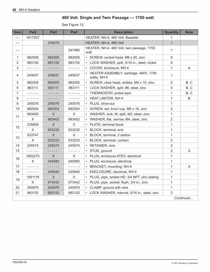
460 Volt: Single and Twin Passage — 1700 wattSee Figure 12.
Item Part Part Part Description Quantity Note— 1617937 HEATER, NH-4, 460 Volt, Baseefa 1— 245676 HEATER, NH-4, 460 Volt 1
— 247480 HEATER, NH-4, 460 Volt, twin passage, 1700 watt 1
1 982006 982006 982006 • SCREW, socket head, M8 x 20, zinc 82 983150 983150 983150 • LOCK WASHER, split, 5/16 in., steel, nickel 63 - - - - - - - - - - - - - - - - - - • COVER, enclosure, NH-4 1 A
4 245637 245637 245637 • HEATER ASSEMBLY, cartridge, 460V, 1700 watts, NH-4 1
5 982005 982005 982005 • SCREW, chez head, slotted, M4 x 10, zinc 5 B, C6 983111 983111 983111 • LOCK WASHER, split, #8, steel, zinc 5 B, C7 - - - - - - - - - - - - - - - - - - • THERMOSTAT, probe-type 1 B, C8 - - - - - - - - - - - - - - - - - - • HEAT LIMITER, NH-4 1 B9 245576 245576 245576 • PLUG, drive-out 1
10 982004 982004 982004 • SCREW, set, knurl cup, M6 x 16, zinc 2
11983400 X X • WASHER, lock, M, split, M3, steel, zinc 1
X 983402 983402 • WASHER, flat, narrow, M4, steel, zinc 2
12235609 X X • PLATE, terminal block 1
X 933232 933232 • BLOCK, terminal, end 1
13933747 X X • BLOCK, terminal, 2 station 1
X 933233 933233 • BLOCK, terminal, contact 214 245574 245574 245574 • RETAINER, wire 215 - - - - - - - - - - - - - - - - - - • STUD, ground 2 A
161602275 X X • PLUG, enclosure ATEX, electrical 1
X 245582 245582 • PLUG, enclosure, electrical 117 - - - - - - - - - - - - - - - - - - • BRACKET, mounting, NH-4 1 A18 - - - - - - 245840 245840 • ENCLOSURE, electrical, NH-4 1
191061116 X X • PLUG, pipe, socket HD, 3/4 NPT, zinc plating 1
X 973442 973442 • PLUG, pipe, socket, flush, 3/4 in., zinc 120 240976 240976 240976 • CLAMP, ground with wire 121 983152 983152 983152 • LOCK WASHER, internal, 5/16 in., steel, zinc 2
Continued...

47NH-4 Heaters
© 2021 Nordson Corporation 1602369-04
Item Part Part Part Description Quantity Note
NS247466 245677 X • RESERVOIR, fluid heating 1
X X 247473 • RESERVOIR, twin passage, fluid heating 1NS X X - - - - - - • • PLUG, expansion, 0.6562 in. 1
22 945018 945018 945018 • • O-RING, hotpaint, 2.734 x 3.000 x 0.139 in. 2 D, E
NS245679 245679 X • • FITTING, 3/8 in., with O-ring 2
X X 246245 • • FITTING, 1/2 in., with O-ring 2
23245583 245583 X • • • FITTING, fluid, 3/8-in. NPTF 2
X X 246244 • • • FITTING, fluid, 1/2-in. NPTF 2
24X 945017 X • • • O-RING, hotpaint, 3/8-in. tube 2 D
945023 X 945023 • • • O-RING, hotpaint, 1/2-in. tube 2 E25 - - - - - - - - - - - - - - - - - - • • BODY, fluid passage 1 A26 245585 245585 245585 • • HOUSING, pressure, NH-4 127 986915 986915 986915 • • RETAINING RING, external, 300, spiral 1
NS245705 245705 X • INSTALLATION KIT, NH-4 1
X X 247481 • INSTALLATION KIT, twin passage, NH-4 1
28X 245777 X • • ADAPTER, thermometer 1
246732 X 246732 • • ADAPTER, thermometer, WP, NH-4 129 901202 901202 901202 • • THERMOMETER 1NS 901933 901933 901933 • • KEY, hexagon, 6 mm 1
30X 972180 X • • ELBOW, male, 37, 1/2−20 JIC x 3/8-in.
NPT, steel 2
972182 X 972182 • • ELBOW, male, 37, 3/4−16 JIC x 1/2-in. NPT, steel 2
31 973022 X X • • NIPPLE, extra heavy, 3/8 x 1.50 in., steel 1
32X 973958 X • • NIPPLE, hex, 3/8 x 1/4 x 1.406 in., steel,
nickel 1
973983 X 973983 • • NIPPLE, hex, 1/2 NPT x 1/4-in. NPT, steel, elni 1
NS 973081 X 973081 • • NIPPLE, hex, 1/2 x 1/2 x 1.89 in., steel, el 133 983417 983417 983417 • WASHER, flat, oversized, 8, steel, zinc 134 983404 983404 983404 • LOCK WASHER, split, M8, steel, zinc 1
35982050 X X • SCREW, hex, cap, M8 x 35, black 1
X 982049 982049 • SCREW, hex, cap, M8 x 25, black 1NS 982169 X X • SCREW, pan, slot, M3 x 16, zinc 1NS 982327 X X • SCREW, chez HD, slot, M4 x 12, zinc 139 245896 245896 245896 • FEED THRU, two-wire 1
NOTE: A. Not serviced separately.
B. Part is included in the Standard NH-4 Thermostat/Heat Limiter Kit, part 106363.
C. Part is included in the Standard Thermostat Kit, part 106283.
D. Part is included in the Single Passage Reservoir Seal Kit, part 106282.
E. Part is included in the Twin Passage Reservoir Seal Kit, part 106310
X. Part not included with this style of heater.
NS: Not Shown

48 NH-4 Heaters
© 2021 Nordson Corporation1602369-04
Stainless Steel NH-4 Heaters115 Volt: Single Passage — 1700 wattSee Figure 13.
Item Part Description Quantity Note— 712905 HEATER, NH-4, stainless steel, 115 Volt 11 982006 • SCREW, socket, head, M8 x 20, zinc 82 983150 • LOCK WASHER, split, 5/16 in., steel, nickel 63 - - - - - - • COVER, enclosure, NH-4 1 A4 245634 • HEATER ASSEMBLY, cartridge, 115 Volt, 1700 watts, NH-4 15 982005 • SCREW, chez head, slotted, M4 x 10, zinc 5 B6 983111 • LOCK WASHER, split, #8, steel, zinc 5 B7 - - - - - - • THERMOSTAT, probe-type 1 B8 - - - - - - • HEAT LIMITER, NH-4 1 B9 245576 • PLUG, drive-out 1
10 982004 • SCREW, set, knurl cup, M6 x 16, zinc 211 983402 • WASHER, flat, M, narrow, M4, steel, zinc 212 933232 • BLOCK, terminal, end 113 933233 • BLOCK, terminal, contact 214 245574 • RETAINER, wire 215 - - - - - - • STUD, ground 2 A16 245582 • PLUG, enclosure, electrical 117 - - - - - - • BRACKET, mounting 1 A18 245840 • ENCLOSURE, electrical, NH-4 119 973442 • PLUG, pipe, socket head, flush, 3/4 in., zinc 120 240976 • CLAMP, ground wire 121 983152 • LOCK WASHER, English, internal, 5/16 in., steel, zinc 222 246658 • BODY, fluid, stainless steel, w/fittings 1
23 971771 • • CONNECTOR, female, hydraulic, comp, 0.50-in. tube x 3/8-in. NPT 2
Continued...

49NH-4 Heaters
© 2021 Nordson Corporation 1602369-04
Item Part Description Quantity NoteNS 246657 • INSTALLATION KIT, stainless steel, NH-4 124 115290 • • ADAPTER, thermometer, stainless steel 125 901202 • • THERMOMETER 1NS 901933 • • KEY, hexagon, 6 mm 126 972718 • • ELBOW, male, 37, 1/2−20 x 3/8-in. NPT 227 973059 • • NIPPLE, hex, 3/8 x 3/8 x 1.45 in., stainless steel 129 983417 • WASHER, flat, M, oversized, 8, steel, zinc 130 983404 • LOCK WASHER, M, split, M8, steel, zinc 131 982049 • SCREW, hex, cap, M8 x 25, black 135 245896 • FEED THRU, two-wire 1
NOTE: A. Not serviced separately.
B. Part is included in the Stainless Steel Thermostat/Heat Limiter Kit, part 106356.
NS: Not Shown

50 NH-4 Heaters
© 2021 Nordson Corporation1602369-04
230 Volt: Single Passage — 1700 wattSee Figure 13.
Item Part Part Description Quantity Note— 246665 HEATER, NH-4, stainless steel, 230 Volt 1— 238502 HEATER, NH-4, 230 Volt, stainless steel, Baseefa 11 982006 982006 • SCREW, socket, head, M8 x 20, zinc 82 983150 983150 • LOCK WASHER, split, 5/16 in., steel, nickel 63 - - - - - - - - - - - - • COVER, enclosure, NH-4 1 A4 245636 245636 • HEATER ASSEMBLY, cartridge, 230V, 1700 watt, NH-4 15 982005 982005 • SCREW, chez head, slotted, M4 x 10, zinc 5 B, C6 983111 983111 • LOCK WASHER, split, #8, steel, zinc 5 C7 - - - - - - - - - - - - • THERMOSTAT, probe-type 1 C8 - - - - - - - - - - - - • HEAT LIMITER, NH-4 1 C9 245576 245576 • PLUG, drive-out 1
10 982004 982004 • SCREW, set, knurl cup, M6 x 16, zinc 211 983402 • WASHER, flat, narrow, M4, steel, zinc 212 933232 • BLOCK, terminal, end 1
12a 235609 • PLATE, terminal block 113 933233 • BLOCK, terminal, contact 2
13a 933747 • BLOCK, terminal, 2 station 114 245574 245574 • RETAINER, wire 215 - - - - - - - - - - - - • STUD, ground 2 A16 245582 245582 • PLUG, enclosure, electrical 117 - - - - - - - - - - - - • BRACKET, mounting 1 A18 245840 - - - - - - • ENCLOSURE, electrical, ATEX, NH-4 119 973442 973442 • PLUG, pipe, socket head, flush, 3/4 in., zinc 120 240976 240976 • CLAMP, ground wire 121 983152 983152 • LOCK WASHER, internal, 5/16 in., steel, zinc 222 246658 • BODY, fluid, stainless steel, with fittings 122 240525 • BODY, fluid, stainless steel, with fittings, EECS 1
23 971771 971771 • • CONNECTOR, female, hydraulic, comp, 0.50-in. tube x 3/8-in. NPT 2 D
Continued...
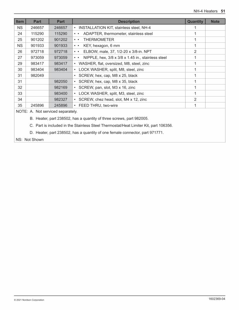
51NH-4 Heaters
© 2021 Nordson Corporation 1602369-04
Item Part Part Description Quantity NoteNS 246657 246657 • INSTALLATION KIT, stainless steel, NH-4 124 115290 115290 • • ADAPTER, thermometer, stainless steel 125 901202 901202 • • THERMOMETER 1NS 901933 901933 • • KEY, hexagon, 6 mm 126 972718 972718 • • ELBOW, male, 37, 1/2-20 x 3/8-in. NPT 227 973059 973059 • • NIPPLE, hex, 3/8 x 3/8 x 1.45 in., stainless steel 129 983417 983417 • WASHER, flat, oversized, M8, steel, zinc 130 983404 983404 • LOCK WASHER, split, M8, steel, zinc 131 982049 • SCREW, hex, cap, M8 x 25, black 131 982050 • SCREW, hex, cap, M8 x 35, black 132 982169 • SCREW, pan, slot, M3 x 16, zinc 133 983400 • LOCK WASHER, split, M3, steel, zinc 134 982327 • SCREW, chez head, slot, M4 x 12, zinc 235 245896 245896 • FEED THRU, two-wire 1
NOTE: A. Not serviced separately.
B. Heater, part 238502, has a quantity of three screws, part 982005.
C. Part is included in the Stainless Steel Thermostat/Heat Limiter Kit, part 106356.
D. Heater, part 238502, has a quantity of one female connector, part 971771.
NS: Not Shown

52 NH-4 Heaters
© 2021 Nordson Corporation1602369-04
380 Volt: Single Passage — 1700 wattSee Figure 13.
Item Part Description Quantity Note— 1617938 HEATER, NH-4, 380 Volt, single passage, stainless steel, Baseefa 11 982006 • SCREW, socket head, M8 x 20, zinc 82 983150 • LOCK WASHER, split, 5/16 in., steel, nickel 63 - - - - - - • COVER, enclosure, NH-4 1 A4 245643 • HEATER ASSEMBLY, cartridge, 380V, 1700 watt, NH-4 15 982005 • SCREW, chez head, slotted, M4 x 10, zinc 5 B, C6 983111 • LOCK WASHER, split, #8, steel, zinc 5 B, C7 - - - - - - • THERMOSTAT, probe-type 1 B, C8 - - - - - - • HEAT LIMITER, NH-4 1 B9 245576 • PLUG, drive-out 1
10 982004 • SCREW, set, knurl cup, M6 x 16, zinc 211 983400 • WASHER, lock, M, split, M3, steel, zinc 112 235609 • PLATE, terminal block 113 933747 • BLOCK, terminal, 2 station 114 245574 • RETAINER, wire 215 - - - - - - • STUD, ground 2 A16 1602275 • PLUG, enclosure ATEX, electrical 117 - - - - - - • BRACKET, mounting, NH-4 1 A18 1602274 • ENCLOSURE, electrical ATEX, NH-4 119 1061116 • PLUG, pipe, socket head, 3/4 NPT, zinc plating 120 240976 • CLAMP, ground with wire 121 983152 • LOCK WASHER, internal, 5/16 in., steel, zinc 222 240525 • BODY, fluid, stainless steel with fitting, Baseef 123 971771 • • CONNECTOR, female, hyd, 0.50 tx. 2NS 246657 • INSTALLATION KIT, NH-4, stainless steel 224 115290 • • ADAPTER, thermometer, stainless steel 125 901202 • • THERMOMETER 1NS 901933 • • KEY, hexagon, 6 mm 126 972718 • • ELBOW, male, 37, 1/2−20 JIC x 3/8-in. NPT 227 973059 • • NIPPLE, hexagon, 3/8 x 3/8 x 1.45 in., stainless steel 1
Continued...

53NH-4 Heaters
© 2021 Nordson Corporation 1602369-04
Item Part Description Quantity Note29 983417 • WASHER, flat, oversized, 8, steel, zinc 130 983404 • LOCK WASHER, split, M8, steel, zinc 131 982050 • SCREW, hex, cap, M8 x 35, black 132 982169 • SCREW, pan, slot, M3 X 16, zinc 134 982327 • SCREW, chez, HD , slot, M4 X 12, zinc 235 245896 • FEED THRU, two-wire 1
NOTE: A. Not serviced separately.
B. Part is included in the Stainless Steel NH-4 Thermostat/Heat Limiter Kit, part 106356.
C. Part is included in the Standard Thermostat Kit, part 106283.
NS: Not Shown
54 NH-4 Heaters
© 2021 Nordson Corporation1602369-04
460 Volt: Single Passage − 1700 wattSee Figure 13.
Item Part Part Description Quantity Note— 248334 HEATER, NH-4, stainless steel, 460 Volt 1— 1617939 HEATER, NH-4, stainless steel, 460 Volt, Baseefa 11 982006 982006 • SCREW, socket, head, M8 x 20, zinc 82 983150 983150 • LOCK WASHER, split, 5/16 in., steel, nickel 63 - - - - - - - - - - - - • COVER, enclosure, NH-4 1 A4 245637 245637 • HEATER ASSEMBLY, cartridge, 460V (1700 watt), NH-4 15 982005 982005 • SCREW, chez head, slotted, M4 x 10, zinc 5 B6 983111 983111 • LOCK WASHER, split, #8, steel, zinc 5 B7 - - - - - - - - - - - - • THERMOSTAT, probe-type 1 B8 - - - - - - - - - - - - • HEAT LIMITER, NH-4 1 B9 245576 245576 • PLUG, drive-out 1
10 982004 982004 • SCREW, set, knurl cup, M6 x 16, zinc 2
11983402 X • WASHER, flat, narrow, M4, steel, zinc 2
X 983400 • WASHER, lock, M, split, M3, steel, zinc 1
12933232 X • BLOCK, terminal, end 1
X 235609 • PLATE, terminal block 1
13933233 X • BLOCK, terminal, contact 2
X 933747 • BLOCK, terminal, 2 station 114 245574 245574 • RETAINER, wire 215 - - - - - - - - - - - - • STUD, ground 2 A
16245582 X • PLUG, enclosure, electrical 1
X 1602275 • PLUG, enclosure ATEX, electrical 117 245898 245898 • BRACKET, mounting 1
18245840 X • ENCLOSURE, electrical, NH-4 1
X 1602274 • ENCLOSURE, electrical ATEX, NH-4 1
19973442 X • PLUG, pipe, socket head, flush, 3/4 in., zinc 1
X 1061116 • PLUG, pipe, socket head, 3/4 NPT, zinc plating 120 240976 240976 • CLAMP, ground wire 121 983152 983152 • LOCK WASHER, internal, 5/16 in., steel, zinc 2
22246658 X • BODY, fluid, stainless steel, with fittings 1
X 240525 • BODY, fluid, stainless steel, with fittings, Baseefa 1
23 971771 971771 • • CONNECTOR, female, hydraulic comp, 0.50-in. tube x 3/8-in. NPT 2
Continued...
55NH-4 Heaters
© 2021 Nordson Corporation 1602369-04
Item Part Part Description Quantity NoteNS 246657 246657 • INSTALLATION KIT, stainless steel, NH-4 124 115290 115290 • • ADAPTER, thermometer, stainless steel 125 901202 901202 • • THERMOMETER 1NS 901933 901933 • • KEY, hexagon, 6 mm 126 972718 972718 • • ELBOW, male, 37, 1/2−20 x 3/8-in. NPT 227 973059 973059 • • NIPPLE, hex, 3/8 x 3/8 x 1.45 in., stainless steel 129 983417 983417 • WASHER, flat, oversized, 8, steel, zinc 130 983404 983404 • LOCK WASHER, split, M8, steel, zinc 131 982049 X • SCREW, hex, cap, M8 x 25, black 1
X 982050 • SCREW, hex, cap, M8 x 35, black 1NS X 982169 • SCREW, pan, slot, M3 x 16, zinc 1NS X 982327 • SCREW, chez HD, slot, M4 x 12, zinc 235 245896 245896 • FEED THRU, two-wire 1
NOTE: A. Not serviced separately.
B. Part is included in the Stainless Steel Thermostat/Heat Limiter Kit, part 106356.
NS: Not Shown

56 NH-4 Heaters
© 2021 Nordson Corporation1602369-04
200 Volt: Single Passage — Japan Only — 1700 wattSee Figure 14.
Item Part Description Quantity Note— 246664 HEATER, NH-4, 200 Volt, stainless steel, Japan 11 982006 • SCREW, socket head, M8 x 20, zinc 82 983150 • LOCK WASHER, split, 5/16 in., steel, nickel 63 - - - - - - • COVER, enclosure, NH-4 1 A4 247532 • HEATER, cartridge, 200V, 1700 watts, NH-4, KK 15 982005 • SCREW, chez head, slotted, M4 x 10, zinc 26 983111 • LOCK WASHER, split, #8, steel, zinc 27 248093 • THERMOSTAT, dual, with bracket 1 B8 - - - - - - • HEAT LIMITER, NH-4 19 245576 • PLUG, drive-out 1
10 982004 • SCREW, set, knurl cup, M6 x 16, zinc 111 245574 • RETAINER, wire 212 - - - - - - • STUD, ground 2 A13 - - - - - - • BRACKET, mounting, NH-4 1 A14 - - - - - - • ENCLOSURE, electrical, NH-4, Japan 1 A15 973442 • PLUG, pipe, socket, flush, 3/4 in., zinc 116 240976 • CLAMP, ground with wire 117 983152 • LOCK WASHER, internal, 5/16 in., steel, zinc 218 246658 • BODY, fluid, stainless steel, with fittings 1
19 971771 • • CONNECTOR, female, hydraulic. comp, 0.50-in. tube x 3/8-in. NPT 2
20 245582 • PLUG, enclosure, electrical 121 983409 • LOCK WASHER, split, M6, steel, zinc 122 - - - - - - • SCREW, button, socket cap, M6 x 16, zinc 1 ANS 246234 • WASHER, retaining 1NS 246657 • INSTALLATION KIT, NH-4, stainless steel 123 115290 • • ADAPTER, thermometer, stainless steel 124 901202 • • THERMOMETER 1NS 901933 • • KEY, hexagon, 6 mm 125 972718 • • ELBOW, male, 37, 1/2−20 x 3/8-in. NPT, stainless steel 226 973059 • • NIPPLE, hex, 3/8 x 3/8 x 1.45 in., stainless steel 127 983417 • WASHER, flat, oversized, 8, steel, zinc 128 983404 • LOCK WASHER, split, M8, steel, zinc 129 982049 • SCREW, hex, cap, M8 x 25, black 130 240764 • WIRE, ground 131 246274 • FEED THRU, two-wire, PTB 1
NOTE: A. Not serviced separately.
B. Part is included in the Manual Reset Thermostat Kit, part 106362.
NS: Not Shown
57NH-4 Heaters
© 2021 Nordson Corporation 1602369-04
Kits and Spare PartsNOTE: � The only way to receive the heat limiter is to order the standard thermostat/heat limiter kit, part 106283, or the stainless steel thermostat/heat limiter kit, part 106356.
Standard NH-4 Thermostat/Heat Limiter Kit
Part Description Quantity106363 THERMOSTAT/HEAT LIMITER SERVICE KIT, NH-4 (aluminum heater) 1- - - - - - • HEAT LIMITER, NH-4 1- - - - - - • THERMOSTAT, probe-type 1982003 • SCREW, chez head, slotted, M3 x 8, steel, zinc 1983400 • LOCK WASHER, split, M3, steel, zinc 1245773 • APPLICATOR, heat conductive paste, 1 cc 1
Standard NH-4 Thermostat Kit
Part Description Quantity106283 THERMOSTAT SERVICE KIT, NH-4 1- - - - - - • THERMOSTAT, probe-type 1982003 • SCREW, chez head, slotted, M3 x 8, zinc 1983400 • LOCK WASHER, split, M3, steel, zinc 1245773 • APPLICATOR, heat conductive paste, 1 cc 1
Stainless Steel NH-4 Thermostat/Heat Limiter Kit
Part Description Quantity106356 STAINLESS STEEL THERMOSTAT/HEAT LIMITER SERVICE KIT, NH-4 1- - - - - - • HEAT LIMITER, NH-4 1- - - - - - • THERMOSTAT, probe-type 1982005 • SCREW, chez head, slotted, M4 x 10, zinc 1983111 • LOCK WASHER, split, #8, steel, zinc 1245773 • APPLICATOR, heat conductive paste, 1 cc 1

58 NH-4 Heaters
© 2021 Nordson Corporation1602369-04
External Adjust KitNOTE: � External adjust can be used on aluminum or stainless steel heaters to allow you to change the temperature without removing the enclosure cover. An arrow will guide you in turning the temperature higher or lower.
Part Description Quantity249489 COVER, adjust thermostat 1131126 • CAP, thermostat, adjusting 1131132 • POINTER, thermostat 1- - - - - - • COVER, enclosure, NH-4, adjusting 1- - - - - - • PLATE WITH HOLE, warning, NH-4 1- - - - - - • SCREW, adjusting 1249493 • SPRING, adjusting 1981000 • SCREW, fillister, 5−40 x 0.25 in., slotted, zinc 1
Manual Reset Thermostat Kit — Japan Only
Part Description Quantity106362 THERMOSTAT SERVICE KIT, manual reset 1248093 • THERMOSTAT, dual, with bracket 1245773 • APPLICATOR, heat conductive paste, 1 cc 1
Standard NH-4 Single Passage Fluid Reservoir Seal Kit
Part Description Quantity106282 SINGLE PASSAGE SEAL SERVICE KIT, heater, NH-4 1945017 • O-RING, hotpaint, 3/8-in., tube 2945018 • O-RING, hotpaint, 2.734 x 3.00 x 0.139 in. 2245773 • APPLICATOR, heat conductive paste, 1 cc 1
Standard NH-4 Twin Passage Fluid Reservoir Seal Kit
Part Description Quantity106310 TWIN PASSAGE SEAL SERVICE KIT, heater, NH-4 1945023 • O-RING, hotpaint, 1/2-in. tube 2945018 • O-RING, hotpaint, 2.734 x 3.00 x 0.139 in. 2245773 • APPLICATOR, heat conductive paste, 1 cc 1
Stainless Steel Alternate Fitting
Part Description Quantity249356 FITTING, 3/8-in. NPTF, with O-ring 1- - - - - - • FITTING, fluid, 3/8-in. NPTF, stainless steel 1945017 • O-RING, hotpaint, 3/8-in. tube 1

59NH-4 Heaters
© 2021 Nordson Corporation 1602369-04
Heater Cartridges (Standard and Stainless Steel Heaters)
Part Description Quantity245633 HEATER CARTRIDGE, 100V/1700W 1245634 HEATER CARTRIDGE, 115V/1700W 1246242 HEATER CARTRIDGE, 115V/500W 1246492 HEATER CARTRIDGE, 115V/1000W 1247532 HEATER CARTRIDGE, 200V/1700W, Japan 1245635 HEATER CARTRIDGE, 200V/1700W (twin passage) 1245636 HEATER CARTRIDGE, 230V/1700W 1246243 HEATER CARTRIDGE, 230V/1000W 1245643 HEATER CARTRIDGE, 380V/1700W 1245637 HEATER CARTRIDGE, 460V/1700W 1
Recommended Spare PartsKeep the following parts in inventory to avoid unplanned downtime. Quantities listed support a single NH-4 heater. Adjust order quantities based on the number of heaters in service.
Part Description Quantity Note106363 SERVICE KIT, thermostat heat limiter, NH-4, aluminum 1106283 SERVICE KIT, thermostat, NH-4 1106356 SERVICE KIT, stainless steel thermostat/heat limiter, NH-4 1106362 SERVICE KIT, thermostat, manual reset (Japan) 1106282 SERVICE KIT, single passage seal, heater, NH-4 1106310 SERVICE KIT, twin passage seal, heater, NH-4 1−−−−−− HEATER ASSEMBLY, cartridge 1 A245774 APPLICATOR, heat conductive paste, carton of 12 applicators, 1 cc each 1
60 NH-4 Heaters
© 2021 Nordson Corporation1602369-04
USE FOR THE FOLLOWING HEATERS: 245672 247747 246238 246490 245673 247477
22
25 29
31
24 23
3228 30
22
27
24
23
30
26
12
3
4
5
6
7
8
10
3334
35
56
11
5611
13
1213
56
1415
9
1039 16
17
18
19
21
20
15
14
6
5
EECS Only
36
37
386
1112a
13a
21
Figure 10 Standard Steel Plated NH-4 Heaters − Single and Twin Passage, 115 and 200 Volt

61NH-4 Heaters
© 2021 Nordson Corporation 1602369-04
USE FOR THE FOLLOWING HEATERS: 246566 248162
18
21
27
28
29
2019
3026
18
23
20
19
28
22
1
2
3
4
24
25
7
9 56
11
1210
8
36 31
13
14
153233
34
11
6
5
3516
1
1712
Figure 11 Standard Steel Plated NH-4 Heaters − Single and Twin Passage, 200 Volt − Japan Only

62 NH-4 Heaters
© 2021 Nordson Corporation1602369-04
USE FOR THE FOLLOWING HEATERS: 245674 247748 247750 247478 245675 247479 245676 247480 1617936 1617937
22
25 29
31
2423
3228 30
2227
24
23
30
26
1
2
3
4
5
6
7
8
10
3334
35
5
6
11
5
6
11
1312
139
10
39 16
17
18
19
211514
6
51
20
38611
12a
13a
36
37
EECS Only
5
6
14
15
Figure 12 Standard Steel Plated NH-4 Heaters − Single and Twin Passage, 230, 240, 380, 460 Volt

63NH-4 Heaters
© 2021 Nordson Corporation 1602369-04
USE FOR THE FOLLOWING HEATERS: 712905 246665 238502 248334 1617938 1617939
EECS Only346
11
32
33
34
6
1112a
13a
232825
2426
27
22
23
26
2930
31
108
7
6
5
1
2
3
4
511
13
1213
9
1035 16
17
18
19
21
1
15
20
5
6
14
56
11
56
14
15
Figure 13 Stainless Steel NH-4 Heaters − Single and Twin Passage, 115, 230, 230, 380 EECS, 460 Volt

64 NH-4 Heaters
© 2021 Nordson Corporation1602369-04
USE FOR THE FOLLOWING HEATER: 246664
1924
2625 23
18
19
25
1
2
3
4
22
21
7
8
9
56
11
1210
31 20
2728
29
13
1415
17
1
1211
6
5
16
Figure 14 Stainless Steel NH-4 Heaters − Single and Twin Passage, 200 Volt − Japan Only

Nordson Corporation • Westlake, Ohio DOC13029-04
EU DECLARATION of Conformity Product: NH-4 Liquid Heater Models: NH-4, Stainless Steel and Aluminum Models.
Description: This is a heater used for heating liquids before they are sprayed or dispensed from an applicator. These liquids could be flammable or non-flammable.
This Declaration is issued under the sole responsibility of the manufacture.
Applicable Directives: 2006/42/EC - Machinery Directive 2014/35/EU - Low Voltage Directive 2014/34/EU - ATEX equipment for use in potentially explosive atmospheres Standards Used for Compliance: EN12100 (2010) EN60079-0 (2012) EN60204 (2018) EN60079-1 (2014) Principles: This product has been designed and manufactured to the directive and standards / norms described above. Type of Protection: - Ex db lIB T3 Gb ATEX Product Certificate: - SGS Fimko Oy, NB 0598 (Helsinki Finland) – BAS00ATEX2170 ATEX Quality System Certificate - SGS Fimko Oy, NB 0598 (Helsinki Finland)
__________________ Date: 16July21 Jeremy Krone Engineering Manager Industrial Coating Systems Amherst, Ohio, USA Nordson Authorized Representative in the EU Person authorized to compile the relevant technical documentation. Contact: Operations Manager Industrial Coating Systems Nordson Deutschland GmbH Heinrich-Hertz-StraBe 42-44 D-40699 Erkrath
Nordson Corporation • Westlake, Ohio DOC13038-01
UK DECLARATION of Conformity Product: NH-4 Liquid Heater Models: NH-4, Stainless Steel and Aluminum Models.
Description: This is a heater used for heating liquids before they are sprayed or dispensed from an applicator. These liquids could be flammable or non-flammable.
This Declaration is issued under the sole responsibility of the manufacture.
Applicable UK Regulations: Supply Machinery Safety 2008 Equipment & Protective Systems Intended for use in Potentially Explosive Atmosphere Regulation 2016 Electrical Equipment (Safety) Regulations 2016 Standards Used for Compliance: EN12100 (2010) EN60079-0 (2012) EN60204 (2018) EN60079-1 (2014) Principles: This product has been designed and manufactured to the Regulations & Norms described above. Type of Protection: - Ex db lIB T3 Gb EX Product Certificate: - Baseefa (Buxton, Derbyshire, UK) – BAS21UKEX0335 Quality System Certificate - SGS Baseefa NB 1180 (Buxton, Derbyshire, UK)
__________________ Date: 16July21 Jeremy Krone Engineering Manager Industrial Coating Systems Amherst, Ohio, USA Nordson Authorized Representative in the UK Contact: Technical Support Engineer
Nordson UK Ltd.; Unit 10 Longstone Road Heald Green; Manchester, M22 5LB. England