Embed Size (px)
Citation preview
GETCO/E/TS – 2XMER01power/ R7 Aug 14
Sign and Seal of Bidder Page 1 of 98
GUJARAT ENERGY TRANSMISSION
CORPORATION LTD.
SARADAR PATEL VIDYUT BHAVAN, RACE COURSE, BARODA – 390 007.
TECHNICAL SPECIFICATIONS
FOR
220/66 kV, 50, 100 & 160 MVA
POWER TRANSFORMER (Without Capitalization)
GETCO/E/TS – 2XMER01power/ R7 Aug 14
GETCO/E/TS – 2XMER01power/ R7 Aug 14
Sign and Seal of Bidder Page 2 of 98
SPECIAL INSTRUCTIONS TO BIDDER Please read following instructions carefully before submitting your bid. 1. All the drawings, i.e. elevation, side view, plan, cross sectional view etc., in
AutoCAD format and manuals in PDF format, for offered item shall be submitted. Also the hard copies as per specification shall be submitted.
2. The bidder shall submit Quality Assurance Plan with the technical bid. 3. The bidder shall have to submit all the required type test reports for the
offered item. Bid without type tests will not be considered for evaluation. 4. The bidder must fill up all the points of GTP for offered item/s. Instead of
indicating “refer drawing, or as per IS/IEC”, the exact value/s must be filled in.
5. All the points other than GTP, which are asked to confirm in technical
specifications must be submitted separately with the bid. 6. The bidder is required to impart training in view of manufacture, assembly,
erection, operation and maintenance for offered item, at his works, to the person/s identified by GETCO, in the event of an order, free of cost. The cost of logistics will be bear by GETCO.
7. Please note that the evaluation will be carried out on the strength of content
of bid only. No further correspondence will be made. 8. The bidder shall bring out all the technical deviation/s only at the specified
annexure.
GETCO/E/TS – 2XMER01power/ R7 Aug 14
Sign and Seal of Bidder Page 3 of 98
QUALIFYING REQUIREMENT DATA (For Supply)
Bidder to satisfy all the following requirements. 1) The bidder shall be Original Equipment Manufacturer (OEM).
The offered equipment have to be designed, manufactured and tested as per relevant IS/IEC with latest amendments.
2) The minimum requirement of manufacturing capacity of offered
type, size and rating of equipment shall be FIVE times tender/ bid quantity. The bidder should indicate manufacturing capacity by submitting latest updated certificate of a Chartered Engineer (CE).
3) Equipment proposed shall be of similar or higher rating and in
service for a minimum period of THREE (3) years and satisfactory performance certificate in respect of this is to be available and submitted.
4) The bidder should clearly indicate the quantity and Single Value
Contract executed during last FIVE (5) years, for the offered equipment. Bidder should have executed one single contract during last five years for the quantity equivalent to tender / bid.
The details are to be submitted in following format,
Sr. No
ITEMS SUPPLIED TO
ORDER REFERENCE No. &
DATE
ITEMS QUANTITY ORDER FULLY
EXECUTED. YES/NO
STATUS, IF ORDER UNDER
EXECUTION
REMARK
e) Equipment offered shall have Type Test Certificates from
accredited laboratory (accredited based on ISO/IEC Guide 25 / 17025 or EN 45001 by the National accredition body of the country where laboratory is located), as per IEC / IS / technical specification. The type test reports shall not be older than FIVE years and shall be valid up to expiry of validity of offer.
Approved ON no. CE(Project)/5439 dtd. 08.01.2007
GETCO/E/TS – 2XMER01power/ R7 Aug 14
Sign and Seal of Bidder Page 4 of 98
INDEX
Sec. No. Particulars Page no.
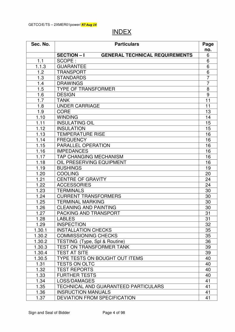
SECTION – I GENERAL TECHNICAL REQUIREMENTS 6 1.1 SCOPE : 6
1.1.3 GUARANTEE 6 1.2 TRANSPORT 6 1.3 STANDARDS 7 1.4 DRAWINGS 7 1.5 TYPE OF TRANSFORMER 8 1.6 DESIGN 9 1.7 TANK 11 1.8 UNDER CARRIAGE 11 1.9 CORE 13
1.10 WINDING 14 1.11 INSULATING OIL 15 1.12 INSULATION 15 1.13 TEMPERATURE RISE 16 1.14 FREQUENCY 16 1.15 PARALLEL OPERATION 16 1.16 IMPEDANCES 16 1.17 TAP CHANGING MECHANISM 16 1.18 OIL PRESERVING EQUIPMENT 16 1.19 BUSHINGS 19 1.20 COOLING 20 1.21 CENTRE OF GRAVITY 24 1.22 ACCESSORIES 24 1.23 TERMINALS 30 1.24 CURRENT TRANSFORMERS 30 1.25 TERMINAL MARKING 30 1.26 CLEANING AND PAINTING 30 1.27 PACKING AND TRANSPORT 31 1.28 LABLES 31 1.29 INSPECTION 32
1.30.1 INSTALLATION CHECKS 35 1.30.2 COMMISSIONING CHECKS 35 1.30.2 TESTING (Type, Spl & Routine) 36 1.30.3 TEST ON TRANSFORMER TANK 39 1.30.4 TEST AT SITE 39 1.30.5 TYPE TESTS ON BOUGHT OUT ITEMS 40 1.31 TESTS ON OLTC 40 1.32 TEST REPORTS 40 1.33 FURTHER TESTS 40 1.34 LOSS/DAMAGES 41 1.35 TECHNICAL AND GUARANTEED PARTICULARS 41 1.36 INSRUCTION MANUALS 41 1.37 DEVIATION FROM SPECIFICATION 41
GETCO/E/TS – 2XMER01power/ R7 Aug 14
Sign and Seal of Bidder Page 5 of 98
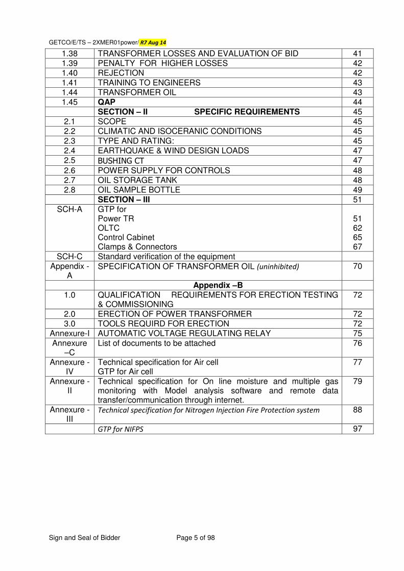
1.38 TRANSFORMER LOSSES AND EVALUATION OF BID 41 1.39 PENALTY FOR HIGHER LOSSES 42 1.40 REJECTION 42 1.41 TRAINING TO ENGINEERS 43 1.44 TRANSFORMER OIL 43 1.45 QAP 44
SECTION – II SPECIFIC REQUIREMENTS 45 2.1 SCOPE 45 2.2 CLIMATIC AND ISOCERANIC CONDITIONS 45 2.3 TYPE AND RATING: 45 2.4 EARTHQUAKE & WIND DESIGN LOADS 47 2.5 BUSHING CT 47
2.6 POWER SUPPLY FOR CONTROLS 48 2.7 OIL STORAGE TANK 48 2.8 OIL SAMPLE BOTTLE 49
SECTION – III 51 SCH-A GTP for
Power TR OLTC Control Cabinet Clamps & Connectors
51 62 65 67
SCH-C Standard verification of the equipment Appendix -
A SPECIFICATION OF TRANSFORMER OIL (uninhibited) 70
Appendix –B 1.0 QUALIFICATION REQUIREMENTS FOR ERECTION TESTING
& COMMISSIONING 72
2.0 ERECTION OF POWER TRANSFORMER 72 3.0 TOOLS REQUIRD FOR ERECTION 72
Annexure-I AUTOMATIC VOLTAGE REGULATING RELAY 75 Annexure
–C List of documents to be attached 76
Annexure - IV
Technical specification for Air cell GTP for Air cell
77
Annexure - II
Technical specification for On line moisture and multiple gas monitoring with Model analysis software and remote data transfer/communication through internet.
79
Annexure - III
Technical specification for Nitrogen Injection Fire Protection system 88
GTP for NIFPS 97
GETCO/E/TS – 2XMER01power/ R7 Aug 14
Sign and Seal of Bidder Page 6 of 98
SECTION: I
DETAIL SPECIFICATION OF 50, 100 & 160 MVA,
220/66 kV POWER TRANSFORMERS
GENERAL TECHNICAL REQUIREMENTS
1.1 SCOPE
1.1.1 This section covers the design, manufacture, assembly, testing at manufacturer’s
works, supply and delivery include loading, transportation & unloading on plinth at
site, of the oil filled, 50/100/160, 220/66 kV power transformers as detailed in the
Schedule of requirements, complete with all accessories required for safe, efficient,
satisfactory and trouble free operation of the equipment.
1.1.2 The scope of work shall also include EITHER complete erection, testing and
commissioning of all the equipments/accessories furnished under this specification
OR only supervision of erection, testing and commissioning of all the equipment
furnished under this Specification, as indicated in Schedule – A of the commercial
bid.
1.1.2.1 Each transformer shall be supplied with (i) Oil storage tank (Steel Tank) as per cl. no. 2.8, (ii) 3 nos. of oil sampling bottles as per cl. no. 2.9, (iii) Fiber optic sensors (iv) On Line Moisture and Gas In Oil Analyser as per Annexure II, (v) Nitrogen Injection System For Protection Against The Fire & Explosion as per
Annexure - III, (vi) On line PD measurement, (vii) GPS/GRPS/GSM based on line
transformer movement tracking system on returnable basis (viii) Condition
controlled maintenance free on line breather as per specification (ix) on line
tan delta of bushing (x) SFRA Kit (xi) Tan delta kit (xii) Air Dryer, if
indicated in Schedule – A of respective tender.
However, Bidder has to quote for the accessories equipments/ Material, indicated in Schedule-A of commercial Bid.
1.1.3 GUARANTEE: The bidder shall among other things guarantee the following: i) Quality and strength of materials used. ii) The bidder shall give the guarantee as satisfactory working of the complete
transformer for 36 months from the date of commissioning of equipment or 42 months from the date of receipt of transformer at site, whichever is earlier. Guarantee period will be reckoned from the date of receipt of 100 % accessories and not from the date of receipt of main tank only.
It may be noted that the service guarantee would be applicable even when the transformers are
erected and operated through any other agency appointed by the GETCO.
1.2 TRANSPORT:
GETCO/E/TS – 2XMER01power/ R7 Aug 14
Sign and Seal of Bidder Page 7 of 98
The equipment to be furnished under this specification shall be packed for transportation in such a manner as may facilitate easy handling and avoiding any damage during transit.
1.3 STANDARDS:
The power transformers covered under this specification shall comply with the
requirements of the latest edition of IS:2026 (amended upto date) except specified
herein. However, in the event the offered equipment conforms to any other standards,
the salient points of difference between the standard adopted and the specified
standard shall be clearly brought out in the bid.
1.4 DRAWINGS:
1.4.1 Drawings in AutoCAD format and in hard copy, incorporating the following particulars shall be submitted by each bidder with the bid. i) General outline drawing showing dimensions, wheel loading, net weight of
transformer, tap change gear, marshalling box, control cubicles required for
all the monitoring devices, etc.
ii) General arrangements of foundations and structural mounting.
iii) Sectional views showing the general constructional features and disposition of
various fittings and sectional view of Core Coil assembly clearly indicating boltless
construction and other necessary specific details.
iv) Dimensions of the largest packages to be transported.
v) Drawing showing the complete details of all class condenser bushing and other
relevant data.
vi) Drawings showing details of Buchholz relay, winding temperature indicator, oil
temperature indicator, air cell, cooling systems, tap changer, all the monitoring
devices and NIFPS, AVR relay, maintenance free breather, etc.
1.4.2 The successful bidder shall submit the following drawings in AutoCAD format and in hard copy for the approval of the purchaser within commencement period. i) General out line drawing showing front, side elevation and plan of the transformer
and accessories with detailed dimensions. The clearances between HV and LV terminals and ground should also to be shown.
ii) Detailed foundation drawings along with structural drawings showing design criteria & loadings.
iii) Drawings of each type of bushings, lifting dimensions, clearance between HT and LT terminals and ground, quantity of insulating oil, name plate details etc. showing various weights and ratio of WT-CT, OT-CT, all bushing CT and details of OLTC & RTCC. The rating / name plate and erection sequence diagram plate shall be as per
IEEMA transformer manual no. 25 - 2014.
iv) Large scale drawings of high, medium and low-tension windings of the transformers showing the nature and arrangement of insulators and terminal connections.
v) Control and annunciation wiring diagram and drawings showing temperature indicator, alarm circuits, Buchholz relay, oil surge relay, PRV, MOG, WTI, OTI,
GETCO/E/TS – 2XMER01power/ R7 Aug 14
Sign and Seal of Bidder Page 8 of 98
AVR relay, OLTC, cooling control , all the monitoring devices and NIFPS, AVR relay,
maintenance free breather, etc.
vi) Drawing showing construction and mounting details of marshalling boxes. vii) Operation and maintenance guide for transformer and OLTC. vii) Detailed drawing showing wheel loadings and its center of gravity. viii) Any other drawing/document required during design review, which will be conducted
during detail engineering, shall be submitted.
1.4.3 The bidder may submit any other drawings found necessary in addition to the
drawings mentioned above or as asked during detailed engineering.
1.5 TYPE OF TRANSFORMER:
1.5.1 The transformers shall be oil-immersed, conventional type, suitable for outdoor
installation. The type of cooling shall be as specified in specific Technical
requirements given in Section-II of this Specification. Transformer size including
radiator width has to be accommodated within 7 Meter on either sides from the center line
of transformer gantry.
1.6 DESIGN:
1.6.1 The transformer shall be used for bi-directional flow of rated power. The transformers
and accessories shall be designed to facilitate inspection cleaning, repairs and for
operation where continuity of supply is the primary consideration. All apparatus shall
be designed to ensure satisfactory operation under sudden variations of load and
voltage as may be met with under working conditions of the systems, including those
due to short circuits.
1.6.2 All materials used shall be of the best quality and of the class most suitable for
working under the conditions specified and shall withstand the variations of
temperature and atmospheric conditions arising under working conditions without
undue distortion or deterioration or setting up of undue stresses in any part & also
without affecting the strength and suitability of the various parts for the work which
they have to perform.
1.6.3 All outdoor apparatus, including bushing insulators with their mountings, shall be so
designed as to avoid pockets in which water can collect. All connections and contacts
shall be of ample cross-sections and surfaces for carrying continuously the specified
current without undue heating and fixed connections shall be secured by bolts or set
screws of ample size, adequately locked, lock-nuts shall be used on stud connection
carrying current.
1.6.4 Radio Interference and Noise level:
The transformer shall be designed with particular attention to the suppression of maximum harmonic voltage, especially the third and fifth so as to minimize interference with communication circuits.
GETCO/E/TS – 2XMER01power/ R7 Aug 14
Sign and Seal of Bidder Page 9 of 98
The noise level of transformer, when energized at normal voltage and frequency with fans and pumps running shall not exceed, when measured under standard conditions,
the values shall not be more than 75 dB, measured as per NEMA standard
publication TR-I.
1.6.5 The transformer shall be capable of being loading in accordance with IS: 6600/IEC-354. There shall be no limitation imposed by bushings, tap changers etc. or any other associated equipments.
1.6.6 The transformer and all its accessories including CTs etc shall be designed to
withstand without any injury, the thermal and mechanical effects of any external short circuit to earth and of short circuits at the terminals of any winding for a period of 3 sec. The short circuit level of the HV and LV system to which the subject transformer will be connected is 40 kA (sym, rms, 3 phase fault on 400, 220 and 132 kV) & 25 kA (sym, rms, 3 phase fault on 66, 22 and 11 kV).
1.6.7 Transformer shall be capable of withstanding thermal and mechanical stresses
caused by symmetrical or asymmetrical faults on any winding.
1.6.8 In the event of an order, design review will be conducted in line with CIGRE
broacher no. 629, April 2013.
1.7 TANK
1.7.1 The transformer tank and cover or BELL type tank shall be fabricated from good
commercial grade low carbon steel suitable for welding and of adequate thickness. The
tank and the cover shall be of welded construction. All seams shall be welded and
where practicable they shall be double welded. The tank wall shall be reinforced by
stiffener of structural steel for general rigidity. The tank shall have sufficient strength
to withstand without permanent distortion (i) filling by vacuum (ii) continuous internal
gas pressure of 0.35 atmospheres with oil at operating level, and (iii) mechanical shock
during transportation. The tank cover shall be bolted to the tank and the transformer
design shall be such that the tank will not be split between the lower and upper cooler
connection for Untanking. The tank covers shall be fitted with pockets at the
position of maximum oil temperature corresponding to MCR (Maximum Continuous
Rating) for RTD sensors and bulbs of oil and winding temperature indicators. It shall
be possible to remove these sensors bulbs without lowering the oil in the tank. The
tank wall penetrations shall be leak proof, suitably marked with respective sensor
identification.
1.7.2 A manhole inspection window with a welded flange & a bolted cover shall be
provided on the tank cover. The manhole shall be of a sufficient size to ease access to
the lower ends of the bushings, terminals etc.
1.7.3 All bolted connections to tank shall be fitted with suitable oil-tight gasket, which shall
give satisfactory service under the operating conditions. Special attention shall be
GETCO/E/TS – 2XMER01power/ R7 Aug 14
Sign and Seal of Bidder Page 10 of 98
given to the methods of making the hot oil-tight joints between the tank and cover as
also between the core and the bushings and all other to ensure that the joints can be
remade satisfactorily and with ease, with the help of semi-skilled labors. Where
compressible gaskets are used, steps shall be provided to prevent over compression.
Bushings, turrets, cover of accessories, holes and other devices shall be designed to
prevent any leakage of water into or oil from the tank. There should not be any
leakage for three year and this should be guaranteed. All the gaskets to be provided
shall be of RC70C or RC80C grade. Necessary tests certificates from
manufacturer shall be submitted along with acceptance test report. The gasket
to be used shall not be older than One year.
1.7.4 Suitable guides shall be provided for positioning the various parts during assembly or
dismantling. Adequate space shall be provided between the covers and windings and
the bottom of the tank for collection of any sediment.
1.7.5 Lifting eyes or lugs shall be provided on all parts of the transformers requiring
independent handling during assembly or dismantling. In addition, the transformer
tank shall be provided with lifting lugs and bosses properly secured to the sides of the
tank for lifting the transformers either by crane or by jacks.
1.7.6 The design of the tank, the lifting lugs and bosses shall be such that the complete
transformer assembly filled with oil can be lifted with the use of those lugs without
any damage or distortions.
1.7.7 The tank shall be provided with two suitable copper alloy or any other suitable
material lugs for the purpose of grounding.
1.7.8 The tank shall be equipped with the following valves with standard screw connection
for external piping. All valves up to and including 100 mm shall be of GM and larger
valves shall be of Cast Iron bodies with GM fittings. They shall be of full way type with
internal screw and shall open when turned counter clock wise when facing the hand
wheel, along with suitable locking in open and close positions.
(i) One drain valve of adequate size with eccentric reducer and flange, located on
the low voltage side of the transformer. This valve shall be equipped with a
small sampling cock. The draining valve must be at bottommost location of
the tank.
(ii) One filter valve of adequate size with eccentric reducer and flange, located at
the top of tank on the high voltage side. The opening of this valve shall be
baffled to prevent aeration of oil.
(iii) One filter valve of adequate size with eccentric reducer and flange, located on
the high voltage side the transformer above the bottom of the tank.
GETCO/E/TS – 2XMER01power/ R7 Aug 14
Sign and Seal of Bidder Page 11 of 98
(iv) Suitable valves shall be provided to take sample of oil from the OLTC chamber during operation of transformer.
(v) A valve of other suitable means shall be providing to fix the on line dissolved
Gas monitoring system to facilitate continuous dissolved gas analysis. Location
and size of the same shall be finalized during detailed engineering. (vi) Pressure relief valve of adequate size & number/s shall be provided on main
tank as well as for OLTC. (vii) All hardware used shall be hot dip galvanised.
(viii) Necessary provision for installation of On Line moisture and gas in oil
monitoring system shall be made for satisfactory performance through
out the life of transformer. Location and size of the same shall be
finalized during detailed engineering.
(ix) Necessary provision shall be made for installation of Nitrogen Injection
Fire Prevention cum Extinguishing System. Location and size of the
same shall be finalized during detailed engineering.
1.8 UNDER CARRIAGE
1.8.1 The transformer tank shall be supported on a structure steel base equipped with forged
steel single flanged wheels suitable for moving the transformer completely with oil.
1.8.2 Jacking pads shall be provided. It shall be possible to change the direction of the
wheels through 900 when the transformer is lifted on jacks to permit movement of the
transformer both in longitudinal and transverse direction. A standard track gauge
(1676 mm) in both longitudinal and transverse directional shall be provided.
1.8.3 Pulling eyes shall be provided to facilitate movement of transformer and they shall be
suitable brazed in a vertical direction so that bonding does not occur when the pull has
a vertical component.
1.9 CORE:
1.9.1 The transformer may be of core or shell type. The core shall be built up with high-
grade non-ageing cold-rolled grain oriented silicon steel laminations having high
permeability and low hysteresis loss. The core material shall be prime CRGO, which
shall be procured directly from manufacturer or through accredited marketing
organization of reputation.
1.9.1(a) The thickness of lamination shall be 0.27 mm or less. Surface insulation of
laminations shall be rust resistant and have high inter laminar resistance. Insulation
shall withstand annealing temperature as high as 850 0C. Insulation shall be resistant
to hot cooling medium. Laminations are not to be punched.
1.9.1(b) Bidder should have in house core cutting facility for proper monitoring & control on
quality & also to avoid any possibility of mixing if prime material with
defective/second grade material. This should be indicated in variably in the QAP. The
purchaser may witness the core-cutting process. In case the in-house core cutting
GETCO/E/TS – 2XMER01power/ R7 Aug 14
Sign and Seal of Bidder Page 12 of 98
facility is not available, then the same shall be carried out in the presence of the
representative of GETCO.
1.9.1(c) The bidder will offer the core for stage inspection and get approval from GETCO
during manufacturing stage. The bidder has to produce following documents at the
time of inspection for confirmation of use of prime core materials at the time of stage inspection for confirmation of use of prime core materials. i) Invoice of supplier ii) Mills of approved test certificates iii) Packing list iv) Bill of lading v) Bill of entry certificate by custom.
To avoid any possibility of mixing of ‘Prime material’ with any other second grade/
defective material, the imported packed slit coils of CRGO materials shall be opened
in the presence of the GETCO representative. Only after the inspection and approval
from purchaser, the core material will be cut in-house OR sent to external agency for
cutting individual laminations. In case the core is sent to external agency for cutting,
the GETCO representative will have full access to visit such agency for the inspection
of the cutting of core.
1.9.2 After being sheared, the laminations shall be treated to remove all burrs and shall be
re-annealed to remove all residual stresses. The insulation of the lamination shall be
inserted to the action of hot transformer oil. Paper and varnish insulation will not be
accepted. The nature of insulation should be specified in the bid.
1.9.3 The core shall be rigidly clamped to ensure adequate mechanical strength and to
prevent vibration during operation. The clamping structure shall be so constructed that
eddy currents will be minimum.
1.9.4 The core shall be provided with lugs suitable for lifting the complete core and coil
assembly of the transformer.
1.9.5 The core and the coil assembly shall be so fixed in the tank that shifting will not occur
when the transformer is moved or during a short circuit.
1.9.6 The transformer shall be designed in such a way that the flux density in the steel core
corresponding to the Rated voltage and the rated frequency shall be not
exceeding 1.727 tesla.
1.9.7 Core and frame terminal should be brought out on transformer top so as to enable
meggering.
1.9.8 The core and the coil assembly shall be so fixed in the tank that shifting will not occur
and cause any damage when the transformer is moved shifted, or during a short
GETCO/E/TS – 2XMER01power/ R7 Aug 14
Sign and Seal of Bidder Page 13 of 98
circuit. The maximum flux density in any part of core or yoke at 10%
continuous over voltage condition shall not exceed 1.9 tesla.
1.9.9 The complete core and core coil assembly of bolt less core type transformer shall be
so assembled that the axis and the plate of outer surface of the coil stack shall not
deviate from the vertical plane by more than 25 mm.
1.9.10 In case transformer with variable flux, the voltage variation which would affect flux
density at every tap shall be kept in view while designing the transformer.
Transformers shall be designed to withstand the following over fluxing conditions:
a) 110 % of maximum density corresponding to
rated voltage
Continuous for all
transformers
b)
125 % & 140 % of max. flux density
corresponding to rated voltage
for 1 minute and 5 sec.
respectively
1.10 WINDING:
1.10.1 The conductor for winding shall be of electrolytic grade copper. The winding shall be
so designed that all coil assemblies of identical voltage ratings shall be
interchangeable and field repairs can be readily done, without special equipment. The
coils shall be supported between adjacent sections by insulating spacers and the
barriers, bracings and other insulation used in the assembly of the windings shall be
arranged to ensure a free circulation of the oil and to reduce hot sports in the windings.
The insulation paper shall be of high quality and the value of degree of
polymerization shall not be less than 1200 Pv and the necessary test
certificate shall be submitted along with the stage inspection report.
Provision shall be made in the tank, for taking sample, in future, of
paper for testing purpose and location shall be easily accessible and
indicated on the transformer tank by affixing special caution plate.
1.10.2 The insulation of the coils shall be such as to develop the full electrical strength of the
windings. All materials used in the insulation and assembly of the windings shall be
insoluble, non-catalytic and chemically inactive in the hot transformer oil, and shall
not soften or otherwise be adversely affected under the operating conditions.
1.10.3 All threaded connections shall be provided with locking facilities. All leads from the
winding to the terminal board and bushings shall be rigidly supported to prevent injury
from vibration. Guide tubes shall be used where practicable.
1.10.4 The windings shall be clamped securely in place so that they will not be displaced or
deformed during short circuits. The assembled core and windings shall be vacuum
dried and suitably impregnated before removal from the treating tank. The copper
GETCO/E/TS – 2XMER01power/ R7 Aug 14
Sign and Seal of Bidder Page 14 of 98
conductors used in the coil structure shall be best suited to the requirements and all
permanent current carrying joints in the windings and the leads shall be welded or
brazed.
1.10.5 Windings shall be subjected to a shrinkage treatment before final assembly, so that
no further shrinkage occurs during service. Adjustable device shall be provided for
taking up any possible shrinkage of coils in service if required.
1.10.6 The conductor shall be transposed at sufficient intervals in order to minimize eddy
currents and equalize the distribution of currents and temperature along the windings.
1.10.7 The tapping winding shall be provided separately from main winding to minimise the
out of balance forces in the transformer at all voltage ratios.
1.10.8 Transformer shall be designed and constructed to withstand, without damage, the
thermal effects on external short circuits (SC) for 3 seconds under conditions specified
in IS:2026 (Part-I, amended up to date).
1.10.9 Bidder shall invariably indicate in the GTP, the cross sectional area of all windings
with respect to the current density adopted.
1.10.10 Bidder shall have to submit the calculations for thermal & dynamic ability to withstand
short circuits.
1.10.11 The cooling calculations will have to be submitted with technical bid.
1.10.12 Fiber optic sensors shall be embedded in each phase of the winding located at
hot spot. The location and details shall be derived & indicated in the respective
drawings along with Justification.
1.11 INSULATING OIL
1.11.1 The oil for first filling together with 10% extra shall be supplied with each
transformer. The oil shall comply in all respects with Appendix – A of the
specification. Particular attention shall be paid to deliver the total oil free from
moisture having uniform quality throughout. The oil may be supplied either in sealed
tanker, or in non-returnable steel drums, which will be opened at site in presence of
GETCO representative. The quantity of oil for first filling & 10% extra of each
transformer shall be stated in the bid, separately.
1.11.2 The supplier of transformer shall furnish test certificates of the insulating power oil
supplied against their acceptance norms, prior to dispatch. Subsequently oil samples
shall be drawn
i) At manufacturer’s works before and after heat run test and shall be tested for following: a) BDV in kVrms b) Moisture content
GETCO/E/TS – 2XMER01power/ R7 Aug 14
Sign and Seal of Bidder Page 15 of 98
c) Dissolved Gas Analysis – samples for DGA shall be taken from sampling device within 24 hrs prior to commencement of heat run test and immediately after this test. The acceptance norms shall be as per IS:10593 (based on IEC-599)
ii) prior to filling in main tank at site and shall it be tested for BDV and moisture content and Corrosive sulphur detection test as per IEC 62353 subjecting oil for 150
0C for 72 hrs for acceptance norms as per Appendix – A.
iii) prior to energisation at site and shall be tested for the following:
a) BDV in kVrms
b) Moisture content
c) Tan Delta at 90 0C
d) Resistivity at 90 0C.
e) Interfacial Tension 1.11.2.1 On Line Moisture and Gas In Oil Analyser For New Transformer With Model
Analysis Software And Remote Data Transfer/Communications through internet shall be provided as per Technical Specifications attached, if indicated in Schedule – A of the commercial bid.
1.12 INSULATION
1.12.1 The dielectric strength of winding in insulation and of the bushings shall conform to
the values given in IS:2026-1962 (as amended up to date).
1.12.1.1 The partial discharges in the transformer at the time of dispatch shall not be
more than 100 pC at 1.5 p.u.
1.12.1.2 The Maximum Limit of value of tan delta at 20 0C shall be 0.5% for windings,
0.4% for bushings and 0.2 % for oil.
1.12.2 For rated system voltage of 220 and 66 kV, the following impulse test voltage may
shall be offered
System Voltage Impulse Test Voltage Power frequency voltage
HV 220 kV 1050 kV 460 kVrms
LV 66 kV 350 kV 160 kVrms
N 36 170 kVp 75 kV rms
1.12.3 The H.V. winding of the transformer shall have graded insulation. The LV winding of
transformer shall have full insulation. The insulation class of the neutral end of the
windings shall be graded to 95 kV (Impulse) and 38 kV (Power frequency) withstand.
1.13 TEMPERATURE RISE:
1.13.1 The transformer shall be installed out-door without any protection from sun and rain.
The maximum hot spot temperature shall be limited to 980C considering annual
weighted ambient temperature of 32 0C with Class-A insulation. However, the hot
spot temperature rise shall be uniform for all the units of the order. In any case, the
hot spot temperature should not be more than 116 0C. F O sensors shall be
placed at hot spot location only and Maximum temperature measured by FO
sensor shall be considered as hot spot temperature. Each transformer shall be
capable of operating continuously at its normal rating without exceeding the
temperature rise limits specified as under
GETCO/E/TS – 2XMER01power/ R7 Aug 14
Sign and Seal of Bidder Page 16 of 98
Winding (measured by resistance) Temp. rise in 0 C ONAN 45
ONAF / OFAF 50
Top oil (measured by thermometer). Temp. rise in 0 C ONAN 40 ONAF / OFAF 45
Cores Not to exceed that permitted for the adjacent part of the winding.
Note: The maximum ambient temperature for the purpose of design shall be
considered as 500C, i.e. even at this temperature, the rise mentioned
above shall not exceed. The gradient in temperature between phases shall
not be more than 10 oC. Heat flow diagram shall be submitted by successful
bidder.
1.13.2 The transformer shall be free from abnormal noise (other than humming) and
vibration. Maximum noise level shall not be more than 75 db.
1.13.3 The transformer will deliver rated current without exceeding temperature rise when
operating on 105% of the rated voltages. The transformer shall be capable of being
operated without danger on any tapping at the rated MVA with voltage of ±10%
corresponding to the voltage of that tapping.
1.14 FREQUENCY:
1.14.1 The transformer shall be suitable for continuous operation with a frequency variation
of ±3% from normal of 50 Hz. without exceeding the specified temperature rise.
1.15 PARALLEL OPERATION:
1.15.1 The similar ratio transformers shall operate satisfactorily in parallel with each other if
connected between high voltage and low voltage bus bars. Also wherever specified,
the transformers shall suitable for parallel operation with existing transformers. The
details of existing transformer shall be considered same as per this
specification.
1.16 IMPEDANCES:
1.16.1 Supplier shall indicate the guaranteed impedance and tolerances and also the upper
and lower limits of impedances which can be offered without an increase in the quoted
price. Impedance shall include positive and zero sequence and shall be expressed in
terms of the branches of the star connected equivalent diagrams, all on the same KVA
base and the range shall be for each branch of the equivalent circuit in turn. The
transformer impedance shall be as specified in Section-II of this Specification.
GETCO/E/TS – 2XMER01power/ R7 Aug 14
Sign and Seal of Bidder Page 17 of 98
1.17 TAP CAHANGING MECHANISM:
1.17.1 ON LOAD TAP CHANGER:
1.17.1.1 Each transformer shall be provided with on- load tap changing mechanism. This shall
be designed for remote control operation from switchboards in the control room. In
addition the tap changer shall include the following:
a. An oil-immersed tap selector – arcing switch for arc suppressing tap selector,
provided with reactor or resistor for reduction of make & break arcing voltage
and short circuits.
b. Motor driven mechanism.
c. Control and protection devices
d. Local & remote tap changer position indicator
e. Manual operating devices
f. Pressure relief device.
1.17.1.2 The on-load tap changer shall be so designed that the contacts do not interrupt arc
within the main tank of the transformer. The tap selector and arcing switch or arc
suppressing selector switch shall be located in one or more oil filled compartments.
The compartment shall be provided with a means of releasing the gas produced by the
arcing. It shall be designed so as to prevent oil in the tap selector compartment from
mixing with the oil in the transformer tank. An oil surge relay shall be provided to
indicate accumulation of gas and alarm thereof.
1.17.1.3 The tap changer shall be capable of permitting parallel operation with other
transformer of the same type.
1.17.1.4 The transformer shall give full load out-put on all taps. The manual operating device
shall be so located on the transformer that it can be operated by an operator standing at
the level of the transformer track. It shall be strong and robust in construction.
1.17.1.5 The control scheme for the tap changer shall be provided for independent control of
the tap changers, when the transformers are in independent service. In addition,
provision shall be made to enable parallel control also at times so that the tap changers
will be operated. Simultaneously, when one unit is in parallel with another so that
under normal conditions the tap changer will not become out of step and this will
eliminate circulating currents. Additional features like master followers and visual
indication during the operation of motor shall also be incorporated.
GETCO/E/TS – 2XMER01power/ R7 Aug 14
Sign and Seal of Bidder Page 18 of 98
1.17.1.6 Necessary interlock, blocking independent, control, must be provided when the units
are in parallel shall be provided.
1.17.1.7 Under abnormal conditions such as may occur, if the contactor controlling one tap
changer sticks, the arrangement must be such as to switch off supply, to the motor so
that an out of step condition is limited to one tap difference between the units. Details
of out of step protection provided for the taps should be furnished in the bid.
1.17.1.8 The contactors and associated gear for the tap change driving motors shall be housed
in a local kiosk mounted adjacent to or on the transformer. The motor shall be suitable
for operation with 3 phase, 415 Volts, 50 Cycles external power supply with MCB /
fuse and single phasing prevention.
1.17.1.9 In addition to the above equipment, the supplier shall supply a separate panel for
installation in purchaser’s control room for remote operation with the following
accessories.
� Raise and lower function.
� Remote tap position indication of digital type, device for indicating ‘ON’ &
‘OFF’ position of fan / motor / pump of cooler control.
� Microprocessor based Annunciation
� Out of step relay and indication.
� Name-plate for each component. An alarm indication lamps showing tap
changing in progress.
� RTCC panel shall be compatible to SCADA operation with IEC
61850 protocol.
� Any other accessory required for satisfactory operation or required during
detail engineering.
� RTCC panel shall be either front or rear door opening. The requirement shall
be informed during detailed engineering.
1.17.1.10 complete particulars of the tap changing gear including the capacity of the motor shall
be stated in the bid.
1.17.1.11 Tap changer shall be suitable for bidirectional power flow. The tap changer rating
shall be more than maximum rated current of transformer.
1.17.1.12 Manual control
The cranking device for manual operation of the OLTC gear shall be removable and
suitable for operation by a man standing at ground level. The mechanism shall be
complete with following:
a) Mechanical tap position indicator which shall be clearly visible
b) A mechanical operation counter
GETCO/E/TS – 2XMER01power/ R7 Aug 14
Sign and Seal of Bidder Page 19 of 98
c) Mechanical stops to prevent over-cranking of the mechanism beyond the extreme
tap position
d) The manual control considered as back up to the motor operated load tap
changer control shall be interlocked with the motor to block motor start-up during
manual operation. The manual operation mechanism shall be labeled to show the
direction of operation for raising the HV terminal voltage and vice-versa
1.17.1 Automatic Voltage Regulating Relays :
1.17.2.1 The AVR relay shall be provided, as per specification indicted in Annexure – I, The
scheme shall detect (i) failure of auxiliary supply, (ii) failure of PT supply and (iii) failure of mechanism to complete the tap changing operation. The relay shall have necessary contacts to be connected to the alarm & / or to the Annunciator available in the panel for visual and audible indication of the failure of trip circuit. The AVR relay shall be compatible to SCADA operation of any make. However, the RTCC panel shall be fully operable even in case of non utilization of AVR relay.
1.17.2.2 All the necessary wiring shall be carried out in RTCC panel and schematic drawings
shall be submitted with the technical bid and during detailed engineering for approval
in duplicate.
1.18 OIL PRESERVING EQUIPMENT:
1.18.1 Air cell type conservator tank is to be provided for oil conservator system, as per
specification given in Annexure – IV attached here with.
1.18.2 In this type of oil preservation system, conservator shall be fitted with a dehydrating
filter breather.
1.18.3 In this system, using a flexible Air cell shall prohibit contact of oil with atmosphere.
(a) Air cell used shall be suitable for continuous operation in an atmosphere of 100 0C to which transformer oil is likely to rise.
(b) The connection of the air cell to the top of the reservoir shall be by an air proof
seal permitting entrance of air into the cell only.
(c) The air cell of the conservator shall withstand the vacuum during installation
and maintenance. Otherwise provision shall be made to isolate the
conservator from main tank during vacuum by providing vacuum sealing valve
in the pipe connecting the main tank with the conservator.
1.19 BUSHINGS: Bushing for 52 kV & above shall be OIP condenser type or RIP
type with Porcelain or Composite Polymer insulator as indicated in schedule -
A of respective tender. In case not mentioned, OIP condenser type with
Porcelain shall be supplied. 36 kV bushing shall be Solid Porcelain or Oil
communicating type.
1.19.1 The bushings shall have high factor of safety against leakage to ground and shall be so
located as to provide adequate electrical clearances between bushings and grounded
GETCO/E/TS – 2XMER01power/ R7 Aug 14
Sign and Seal of Bidder Page 20 of 98
parts. Bushings of identical voltage rating shall be interchangeable. All bushings shall
be equipped with suitable terminals of approved type and size & shall be suitable for
bimetallic connection. The insulation class of the high voltage neutral bushing shall be
properly coordinated with the insulation class, of the high voltage winding.
1.19.2 Each bushing shall be so coordinated with the transformer insulation so that all flash
over will occur outside the tank.
1.19.3 All main winding and neutral leads shall be brought out through “out door” type
bushings which shall be so located that the full flashover strength will be utilized and
the adequate phase clearance shall realized.
1.19.4 All porcelain used in bushings shall be of the wet process, homogeneous and free from
cavities or other flaws. The glazing shall be uniform in colour and free from blisters,
burrs and other defects.
1.19.5 The bushings for 66 kV and above shall be of the oil filled condenser type
(hermetically sealed) and shall conform to the latest edition of IS: 2099 & IS: 3347.
36 kV bushings for neutral shall be solid porcelain or oil communicating type.
Dimensions shall confirm to IS: 2099 & IS: 3347 (Part – V). The characteristics of the
oil used in the bushings shall be the same as that of the oil in the transformer. Oil
filled condenser type bushing shall be provided with fittings viz. oil level gauge,
oil filling plug, Tap for capacitance and Tan delta test, etc.
1.19.6 All bushings shall have puncture strength greater than the dry flashover value.
1.19.7 Main terminals shall be compression type and shall be suitable for TWIN ‘ACSR
MOOSE’ conductor or as specified in Schedule – A of respective tender. The spacing
between the bushings must be adequate to prevent flash over between phases under all
conditions of operation.
1.19.8 Deleted.
1.19.9 The bidder shall give the guaranteed withstand voltage for the above and also furnish a
calibration curve with different settings of the coordination gap to the GETCO to
decide the actual gap setting. Bidder’s recommendations are also invited in this
respect.
1.19.10 Bushing CTs shall be provided for REF protection as specified in Section – II Cl. 2.5.
The bushing shall be removable without disturbing the CTs.
1.19.11 Bushings of identical rating shall be interchangeable.
1.19.11a The tan delta and capacitor measurement tap shall be provided. Test taps relying on
pressure contacts against outer earth layer of the bushing is not acceptable.
1.19.12 The STC rating shall be 40 kA for 3 sec for 132 kV & above class and 25 kA for 3 sec
for 66 kV and below class.
GETCO/E/TS – 2XMER01power/ R7 Aug 14
Sign and Seal of Bidder Page 21 of 98
1.19.13 The height of live part shall be so arranged that minimum clearance up to
plinth shall be maintained as per following safety clearances. The phase to
phase and phase to earth clearances shall be as per CBIP guideline.
400 kV Live Part to ground clearance up to plinth – 8000 mm 220 kV Live part to ground clearance up to plinth – 5500 mm 33 kV Live part to ground clearance up to plinth – 3600 mm
1.19.14 Mounting dimensions of bushings shall be matched with other makes also. 1.19.15 Polymer / composite insulator shall be seamless sheath of a silicon rubber compound.
The housing & weather sheds should have silicon content of minimum of 30% by weight. It should protect the bushing against environment influences, external pollution and humidity. It shall be extruded or directly moulded on the core. The interface between the housing and the core must be uniform and without voids. The strength of the bond shall be greater than tearing strength of polymer. The manufacturer shall follow non destructive technique (NDT) to check the quality of jointing of the housing interface with the core. The technique being followed with detailed procedure and sampling shall be decided during finallsation of MQP.
The weather sheds of the insulators shall be of alternate of shed profile as per IEC
60815-3. The weather sheds shall be vulcanized to the sheath (extrusion process) or moulded as part of the sheath (Injection moulding process) and free from imperfections. The vulcanization for extrusion process shall be at high temperature and high pressure. Any seams / burrs protruding axially along the insulator, resulting from the injection moulding process shall be removed completely without causing any damage to the housing. The track resistance of housing and shed material shall be class 1A4.5 according to IEC 60587. The strength of the weather shed to sheath interface shall be greater than the tearing strength of the polymer. The composite insulator shall be capable of high pressure washing.
End fittings shall be free from cracks, seams, shrinks, air holes and rough edges. End
fittings should be effectively, sealed to prevent moisture ingress, effectiveness of sealing system must be supported by test documents. All surfaces of the metal parts shall be perfectly smooth with the projecting points or irregularities which may cause corona. All load bearing surfaces shall be smooth and uniform so as to distribute the loading stresses uniformly.
The hollow silicon composite insulators shall comply with the requirements of the IEC
publications. IEC 61462 and the relevant parts of IEC 62217.The design of the composite insulators shall be tested and verified according to IEC 61462 (type and routine test).
All type test & routine test as per applicable standards for OIP Porcelain or Composite
Insulator bushing shall be submitted for approval. Spare bushings (draw lead / draw rod) shall be supplied with lead / rod.
1.20 COOLING:
1.20.1 AIR BLAST, FORCED COOLED OIL TRANFORMERS:
1.20.1.1 Each cooler unit shall consist of a totally enclosed, oil immersed motor pump and a
forced air cooled radiators. Motor and pump shall be placed in an oil tight
container with motor leads brought through hermetically sealed bushings. Each cooler
unit shall be detachable from the transformers without disturbing the oil in the
transformer tank. Moving parts of motor and pump shall be readily removable without
dismantling of cooler and with minimum spillage of oil. Fans shall be located so that
GETCO/E/TS – 2XMER01power/ R7 Aug 14
Sign and Seal of Bidder Page 22 of 98
they are readily accessible for inspection and repair. Heat exchangers, fans and oil
pumps shall be completely interchangeable.
1.20.1.2 All coolers shall be attached to and mounted on the transformer tank or provided
separately. The separate cooler banks shall be provided on right side of transformer
looking from 220 kV side.
1.20.1.3 Cooler shall be so designed as to be accessible for cleaning and painting to prevent
accumulation of water on the outer surfaces completely, drain oil in the tank and to
ensure against formation of gas pockets when the tank is being filled.
1.20.1.4 ONAN/ONAF/OFAF cooled transformers shall be provided with
requisite number of radiator banks (Minimum 2 nos). Besides the
requisite number of oil pumps and fans required for normal operation,
each radiator bank shall be provided with one standby fan and oil
pump as applicable.
1.20.1.5 Cooler units shall be connected to the tank by machined steel flanges welded to cooler
units and to the tank and provided with gaskets. Each cooler unit shall be provided
with an indicting shut-off valve, which can be fastened in either open or closed
position. A separate oil-tight black flange shall be provided for each tank connection
for use when the cooler unit is detached. Each cooler unit shall have two lifting eye at
top & one lifting eye at bottom with, an oil drain at the bottom and a vent at the top.
1.20.1.6 An oil flow indicator with alarm contacts shall be furnished with each pump assembly
to indicate normal pump operation and direction of oil flow.
1.20.1.7 Fans or blowers for air blast cooling shall be mounted so as to ensure that no damage
to the coolers can arise from vibration of the fans. Wire mesh screens shall be fitted to
prevent accidental contact with the blades, the mesh being not greater than 2.5 cm.
1.20.1.7(a) The fan or blowers wiring shall be in such a way that any fan can be operated as of
group II or standby.
1.20.1.8 In cases of ONAN/ONAF/OFAF type cooling, the transformer shall be capable of
giving a continuous output of at least 50% of rated full output with all the artificial
cooling out of service and without exceeding the temperature rise. In case of
ONAN/ONAF type of cooling the transformer shall be capable of giving continuous
output of at least 75% of the rated full output with the artificial oil force cooling out of
service and without exceeding temperature rise. In case of ONAN or ONAF type of
cooling the transformer shall have two sets of radiators.
1.20.1.9 For OFAF cooled transformers with ONAN rating, piping system shall permit
bypassing of oil pump and operation of the transformer at its ONAN rating, in case
forced oil system develop any troubles.
GETCO/E/TS – 2XMER01power/ R7 Aug 14
Sign and Seal of Bidder Page 23 of 98
1.20.1.10 ONAN/ONAF/OFAF cooled transformers shall be designed to operate at no load for 4
hours without any cooler unit in service. ONAN/ONAF cooled transformers shall also
be capable of delivering its rated MVA for 20 minutes with the loss of all cooling
equipment while the transformer is carrying full load.
1.20.1.11 The cooling calculation shall be furnished with radiator drawing for specified
temperature rise along with the technical bid.
1.20.1.12 The cooling fan shall be operated by OTI & FOS at 2 sets of temperatures for fan
GR I & GR II. The oil pump shall be also operated by WTI & FOS.
1.20.1.13 In case of ONAN /ONAF / OFAF cooled transformers, provision of automatic
changeover from main supply to stand by auxiliary supply should be available in
case of failure of main supply. Necessary alarm etc. for this may also be included.
1.20.2 NATURAL OIL COOLED TRANSFORMER
1.20.2.1 The radiating sections/tubes provided shall have sufficient cooling surface to limit the
temperature rise to the values specified under clause – 1.13 of this specification. The
radiating sections/tubes shall be connected to the tank cooler assembly headers by
machined steel flanges with adequate gaskets to avoid oil leakage. Each radiator unit
shall be provided with positive operated butterfly and lockable – non interchangeable
type oil leak proof shut-off valve, which can be fastened in either closed or open
position. A separate oil tight flange shall be provided for each tank connections for use
when the radiator unit or cooler assembly is detached. It shall be possible to take out
any of the radiating tubes without disturbing the transformer. Each radiator unit shall
have a lifting arrangement and oil drain at the bottom and a vent at the top.
1.20.2.2 The radiators shall be so designed as to prevent any accumulation of water on the outer
surface or formation of gas pockets when the tank is being filled.
1.20.3 COOLER CONTROL:
1.20.3.1 Cooler units shall be suitable for operation with 415 Volts, 3 phase, 50 Hz external
power supply.
1.20.3.2 Control equipment for oil pump and for motors shall be mounted in a marshalling
cabinet adjacent to the transformer and it shall include the necessary contactors with
automatic control and annunciation equipment and provision for manual control.
The cabinet shall be 3 mm thick steel sheets having rain shed and it should be tested
for IP 55 degree of protection. The separate indicating must be provided for main &
stand by 3 phase supply. The cabinet shall have two-illumination circuit to be
operated from both the side. The cable tray shall be provided from ground for
aesthetic cable entry. The heater with thermostat of suitable rating shall be provided
GETCO/E/TS – 2XMER01power/ R7 Aug 14
Sign and Seal of Bidder Page 24 of 98
line the cabinet. The bottom of the cabinet shall have enough cable entry with gland
and it shall include the necessary contractors with automatic control and equipment
and provision for manual control & remote indication.
1.20.3.3 A single metal enclosed main isolating switch with Miniature Circuit Breakers shall be
provided for the cooling plant contractor group.
1.20.3.4 The switching in or out of the cooling equipment shall be controlled by winding
temperature and there shall be provision for automatic switching in or out at
predetermined temperature levels which should be capable of adjustment and setting at
will. Hunting of the cooling equipment should be avoided by suitable auxiliary timer
relay. The arrangement of winding temperature and oil temperature indicator shall
be at such height that it is easy to read by naked eye by an operator from ground.
1.20.3.5 The bidder shall specify the loading of the transformers in case of failure of one or
more set of fans or pumps.
1.20.3.6 In case of ONAN/OFAF cooled transformers, provision of automatic changeover from
main supply to stand by auxiliary supply should be available in case of a failure of
main supply. Necessary alarm and indication etc. for this may also be included.
1.20.3.7 The bidder shall provide for fan & pump indicator in the cooling circuit in the remote
control panel.
Following lamp indications with annunciation shall be provided in cooler control cabinet
a) Control supply failure
b) Cooling fan failure for each bank
c) Cooling pump failure for each pump
d) No oil flow or Reverse flow for pumps
e) Common thermal overload trip
One potential free initiation contact for all the above conditions shall be wired independently to
the terminal blocks of cooler control cabinet.
1.20.3.8 The fan circuit shall be operated at different temperatures for group I fans and group II
fan from OTI & FOS. The pump circuit shall be also operated from same WTI & FOS
contacts at different temperatures.
1.20.3.9 The connection shall be bolted type having CB – 30 and CT connector shall be of
disconnecting link type, which can be shorted for testing or checking circuit.
1.21 CENTRE OF GRAVITY:
GETCO/E/TS – 2XMER01power/ R7 Aug 14
Sign and Seal of Bidder Page 25 of 98
1.21.1 The center of gravity of the assembled transformer shall be low and as near the vertical
center line as possible. The transformer shall be stable with or without oil.
1.22 ACCESSORIES:
1.22.1 Each transformer shall be provided with the following accessories
(i) Dial Image sensing type mercury free thermometers for oil;
(a) For ONAN/ONAF and ONAN/OFAF Transformer
The dial Image sensing type indicting thermometers of robust batten
mounted on the side of the transformer at a convenient height to read the
temperature in the hottest part of the oil and fitted with alarm and trip
contacts and contacts for switching in and switching out the cooling
system at pre-determined temperatures.
The OTI shall be compatible for remote SCADA operation, for which
separate ROTI shall be provided.
(b) For ONAN Transformers
A dial Image sensing type mercury free thermometer for indicating oil
temperature fitted with maximum pointer and adjustable alarm and trip
contacts.
(c) The switch contacts shall have adequate AC and DC rating. (ii) One winding hot spot winding temperature detector in LT winding of each
phase having 4 sets of contacts, as under:
(a) For ONAN/ONAF and ONAF/OFAF Transformer
It shall be indicating type, responsive to the combination of top
temperature and winding current, calibrated to follow the hottest spot
temperature of the transformer winding. The winding temperature
detector shall operate a remote alarm and trip at predetermined
independent temperature in the even the hottest spot temperature
approaches a dangerous value.
(b) For ONAN/ONAF and ONAN/OFAF Transformer
In the case of ONAN/ONAF/OFAF type transformers it shall
automatically actuate the fans/pumps also.
c) Accuracy class of WTI shall be +/- 1.5% or better.
d) Any special cable required for shielding purpose, for connection
between cooler control cabinet and remote WTI control circuit, shall be
in the scope of supplier. Only one RWTI with a four point selector
switch shall be provided for all the windings.
The WTI shall be compatible for remote SCADA operation, for which
separate ROTI shall be provided.
(e) The switch contacts shall have adequate AC and DC rating. ii-A) Separate PT 100 resistance temperature detector (RTD) for ROTI &
RWTI shall be provided. RTD shall be provided with PT100 temperature sensor having nominal
resistance of 100 ohms at zero degrees centigrade. The PT100 temperature sensor shall have three wire ungrounded system. The calibration shall be per IEC 60751-2 or equivalent. The PT100
GETCO/E/TS – 2XMER01power/ R7 Aug 14
Sign and Seal of Bidder Page 26 of 98
temperature sensor may be placed in the pocket containing temperature sensing element.
RTD shall include image coil for OTI system and shall provide dual output 4-20 mA for remote OTI & SCADA system individually.
RTD shall include image coil, Auxiliary CTs, if required, for WTI system and shall provide dual output 4-20 mA for remote OTI & SCADA system individually. The transducer shall be installed in the individual marshalling box.
(ii) One magnetic type oil level gauge with low alarm contacts and dial showing
minimum, maximum and normal oil levels. The gauge shall be readable from
the transformer base level for main tank conservator over and above the
prismatic type oil level gauge.
(iv) One oil filling valve (inlet).
(v) One oil drain valve
(vi) One filter valve located at the top of tank on the H.V. Side.
(vii) One filter valve located near the bottom of tank of the H.V. side of the
transformer.
(viii) Oil sampling devices.
(ix) Pressure relief device and Sudden/Rapid pressure rise release relay
A safety valve of the chimney type shall be provided to detect
pressure rise inside the transformer and shall operate to prevent
tank rupture. Suitable pipe with bend shall be provided on
opening to suitably direct sudden splash of oil to suitable location
to prevent damage or any injury. Necessary tripping contacts
shall be provided in terminal box having ingress protection of IP55
with connecting cable up to marshaling cubical. Termination
shall be push and plug type.
(x) A Buchholz relay with alarm and tripping contacts to detect accumulation of
gas and sudden changes of oil pressures, complete with two shut-off valves and
flange coupling to permit easy removal without lowering oil level in the main
tank, a bleed valve for gas venting and test valve. The relay shall be provided with a test cock suitable for a flexible pipe connection for checking its operation & taking gas sample. A copper or Stainless Steel tube shall be connected from the gas collector to a valve located at 1200 mm above ground
level. Necessary alarm & tripping contacts shall be provided in terminal
box having ingress protection of IP55 with connecting cable up to
marshaling cubical. Termination shall be push and plug type. The switch
shall be mercury free.
(xi) Radiators complete with pumps, motors, fans etc. as described in clause 1.20.
(xii) (a) An oil conservator
(b) Oil preserving equipment complete in all respects as described in cl. 1.18.
GETCO/E/TS – 2XMER01power/ R7 Aug 14
Sign and Seal of Bidder Page 27 of 98
(xiii) Eye bolts and lugs on all parts for ease of handling.
(xiv) Four grounding terminals one on each side of transformer.
(xv) Diagram and rating plate
(xvi) One set of equipment for control, protection, indication and annunciation for
each transformer comprising motor contractors, detecting elements or devices,
indicating apparatus, instruments relays, annunciates etc.
(xvii) Suitable weather proof cubicle for housing the control equipment, terminal
blocks etc. (one for each transformer) and one indoor cubicle for each
transformer for remote control of radiators, on load tap changer alarm and
indicating devices.
(xviii) [A] Dehydrating Filter Breather for Main/ OLTC conservator. Silica gel breather to be fitted with conservator shall be designed such that:
a) It is of clear view type design so that moisture absorption indication by change in colour of silica gel is visible from a distance
b) Passage of air is possible through silica gel only c) Height of breather mounting shall not be less than 1200 mm from rail top
level d) Size of breather shall be such that it content 5 kG of silica gel in it e) The nos. of breathers shall be Three or more as required for main
conservator and shall be Two for OLTC conservator f) Silica gel is isolated from atmosphere by an oil seal.
xviii) [B] Condition controlled maintenance free dehydrating breather
for main conservator (if indicated in the Schedule – A of
respective tender):
The main Transformer tank conservator shall be fitted with a silica gel
Breather of the Maintenance-Free type at a height of 1200 mm from rail
top level. Each Silica gel breather shall be equipped with a humidity
sensor, a condition based microprocessor control unit and LED status
indication. The function shall be tested via a test button. A stainless steel
filter at the bottom shall protect the silica gel chamber against external
environment influences. This condition controlled application should be
environmental friendly.
Dehydrating breathers work according to the following principle. When
the oil conservator suctions in air (e.g., due to the reduced load), the air
flows through a filter made of high-grade steel wire mesh to the inside
of the device. This filter & the dust cap, filters the dust, sand and other
dirt particles from the air. The filtered air flows through the desiccant
chamber filled with colorless, moisture adsorbing pellets and are
dehydrated. The dehydrated air rises further via the pipe in the oil
conservator. The dehydrating breather is mounted on the pipe to the oil
conservator. A suitable counter-flange must be installed on the pipe to
mount the dehydrating breather. The desiccant contained in the drying
GETCO/E/TS – 2XMER01power/ R7 Aug 14
Sign and Seal of Bidder Page 28 of 98
assembly is dehydrated using sensor which is controlled by the built-in
heating unit, thus obviating the need for periodic desiccant replacement.
The Maintenance Free Type of Breather shall fulfill the objectives like
reduced site inspections, no storage or replacement of the desiccant no
pollution and disposal problem of the used up desiccant.
Technical requirements:
1. Material & External Construction of the Breather shall be such that all
external parts are suitable for outdoor use & resistive to transformer oil,
ultraviolet rays, pollution & salt water.
2. The equipment shall work without any trouble for ambient temperature
between 0o C to +80
oC.
3. Degree of Protection shall be at least IP55.
4. The control unit shall be provided on the breather equipped with suitable
heater to prevent moisture condensation.
5. Status LEDs for local display shall be provided on breather along with
suitable contacts to take the signal to remote control room.
6. The moisture and temperature measurement system (sensor) installed
should be modular making it easy to replace the same if at all the same
is necessary during the service of breather. A self diagnostic system shall
be provided with LED indication and remote signal through a relay shall
be provided.
7. Micro fuse and an additional built in line filter shall be provided to
protect against over voltages & to avoid failures caused by high-
frequency interference.
8. The control unit in the breather shall provide analogue output signal of
4-20mA and also shall be equipped with a RS 485 port for data logging.
9. Suitable Data Logger shall also be provided in the control unit.
10. The size and type of Condition controlled maintenance free dehydrating
breather to be provided shall be selected on the basis of volume of oil of
the offered transformer.
11. The Breather shall also be equipped with integrated test button which
should allow to carry out a self-test and to check the functions like relay
circuits, heating or the signal transmission in the control room, etc. at
any time.
12. Rated supply Voltages shall be 230 V AC or DC.
Rated insulation level - 500VAC 50 Hz, 1 min withstand voltage
500VAC 50 Hz, 1min. withstand, analog output against ground;
2.5kVAC 50 Hz, 1 min. withstand, relay contact against ground
13. Type Test report for Degree of protection for control unit shall be
submitted.
14. Successful bidder shall offer all acceptance tests on Condition controlled
maintenance free dehydrating breather and submit routine test report
GETCO/E/TS – 2XMER01power/ R7 Aug 14
Sign and Seal of Bidder Page 29 of 98
during acceptance of transformer for each supply. List of acceptance /
routine tests shall be submitted with the tender.
All applicable clauses for breather shall be treated accordingly.
(xix) Conservator and Buchholz (Surge) relay for on load tap changer.
(xx) Suitable compression type terminal connectors for HV, LV & Neutral bushings (xxi) Suitable ladder or climbing devices.
(xxii) Tap changer remote control panel complete with all accessories with SCADA compatibility, suitable for IEC 61850 communications, front/rear door, to be installed in the Purchaser’s control room.
(xxiii) A twin tinned copper strip grounding conductor of 50 x 6 mm size shall be
provided from the neutral terminal to transformer base for connection to the
sub-station grounding grid. Necessary pin insulator clamps, bolts etc. shall be
supplied for this grounding purpose. Neutral bushing to grounding conductor shall be made through twin copper flexible strip of size 50 x 10 mm.
xxiv) Man hole opening and Inspection covers
xxv) Protected type mercury or alcohol in glass thermometer
xxvi) Bottom and top filter valves with threaded male adaptors, bottom
xxvii) Rating and diagram plates on transformer and auxiliary apparatus
xxviii) Flanged bi-directional wheel with anti earth quake clamps
xxix) Cooler control cabinet
xxx) Bushing CTs xxxi) Oil flow Indicator with alarm contacts
xxxii) On Load Tap Changing Gear xxxiii) Drain valves/plugs shall be provided in order that each section pipe work can
be drained independently xxxiv) Terminal Marking plates of Stainless Steel sheet having minimum thickness of
2 MM xxxv) Valves Schedule plates of Stainless Steel sheet having minimum thickness of
2 MM
xxxvi) Skids at the base of transformer. xxxvii) Stranded Copper double PVC, control cable of 1100 V grade. xxxviii) Fiber Optic sensor temperature indicator system: Temperature measurement of Oil
and winding shall also be done using Fiber Optic Sensors, meeting following criteria:
1. System shall be fiber optic rugged, proven technology. The probes shall be directly
installed in each phase of transformer to measure the winding hotspot and top oil
temperature. There will be total eight probes inside the transformer, out of which
two probes shall be installed for top & bottom Oil temperature measurement of
the transformer.
2. Out of remaining six (6) Fiber Optic probes, one each should be installed in each
phase at the hottest spots of HV & LV winding. The hottest spot location shall be
justified by suitable software. The locations of the probe shall be proposed by the
Manufacturer and finalized by agreement with the purchaser.
3. Probes shall be able to be completely immersed in hot transformer oil & they shall
withstand exposures to hot kerosene vapor during the transformer installation
drying process.
4. Temperature range of the system should be -30ºC to +200 ºC & accuracy of ±1%
with no recalibration required.
GETCO/E/TS – 2XMER01power/ R7 Aug 14
Sign and Seal of Bidder Page 30 of 98
5. Probes shall be 200 μm all silica double PFA Teflon jacketed, Kevlar cabled / PTFE
(Teflon) jacketed cable fiber with perforated outer jacket to allow complete oil filling
and white Teflon protective Helix wrap for improved visibility and mechanical
strength.
6. System should include analog outputs for each measurement channel.
Temperature resolution of the analog outputs shall be ±0.1 ºC and the systems
shall offer a user programmable temperature alarm outputs with 6 relays, alarm
lights and controller system status indicators. All inputs and outputs of the system
shall meet the requirements of surge test of IEEE C37.90.1-1989 in which a 3000V
surge is applied to all the inputs and outputs without permanent damage to the
instrument.
7. The system shall be capable of retaining temperature data of 90 or more days at
rate of One reading per minute and should retain maximum temperature of each
channel until reset.
8. The manufacturer should submit data showing that the probes are located in the
hottest point of the winding.
9. The Fiber Optic cable should be brought out of the main tank through tank wall
penetrator feed through plate. The feed through plate shall be welded on the tank.
The external fiber optic extension cable shall then be run to main control cabinet,
routed inside the conduits with large bend radiuses.
10. The controller shall be housed in cooler control cabinet. Temperature rise test
measurements shall be made with FO thermometers. The equipment shall be
operational during temperature tests and demonstrated during these tests. During
probe verification, the hottest probes for each phase shall be identified, and
temperature data for all probes recorded and reported in the test report.
11. Transformer manufacturer shall confirm for full guaranteed performance of
transformer with provision of FO sensors system. FO system shall cover all required
accessories to indicate temperatures at local, remote and shall be SCADA
compatible. Suitable change over facility of alarm & control contacts shall be
provided for conventional thermal image type temperature indicators and fiber
optic temperature indicators.
12. The FO system shall have suitable length of FO cable, sensor and probes.
13. The output of FO system shall be suitable for PC interface with USB port. All
required software shall be provided.
14. Any other accessories required for satisfactory operation of fiber optic sensor
temperature measurement system shall be provided.
15. All the type tests reports as per IEC 60076-7 table E1 Annexure – E3 shall be
submitted with the technical bid. Acceptance tests shall be performed as per
relevant standard.
16. Services of FO system supplier during manufacturing, testing, commissioning and
after sales even beyond guarantee period shall have to be arranged and provided
by the bidder.
17. All the data shall be recorded with time stamping and shall be retrieved & recorded
easily.
Any other fitting / accessories other than listed above, required for satisfactory operation of the transformer are deemed to be included
1.22.2 The equipment and accessories furnished with the transformer shall be suitably
mounted on the transformer, for satisfactory operation, inspection and maintenance
and the mounting details shall be subject to the approval of the purchaser. All valves
GETCO/E/TS – 2XMER01power/ R7 Aug 14
Sign and Seal of Bidder Page 31 of 98
shall be provided either with blind companion flanges or with pipe plugs for
protection.
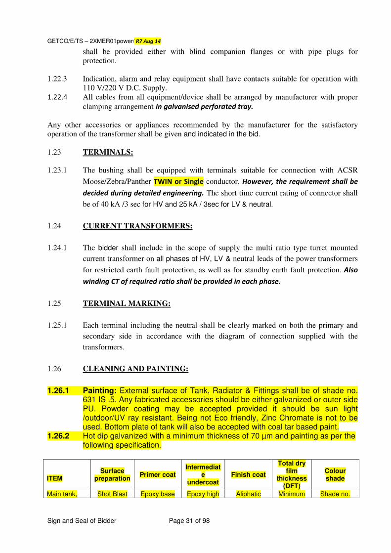
1.22.3 Indication, alarm and relay equipment shall have contacts suitable for operation with
110 V/220 V D.C. Supply.
1.22.4 All cables from all equipment/device shall be arranged by manufacturer with proper
clamping arrangement in galvanised perforated tray.
Any other accessories or appliances recommended by the manufacturer for the satisfactory
operation of the transformer shall be given and indicated in the bid.
1.23 TERMINALS:
1.23.1 The bushing shall be equipped with terminals suitable for connection with ACSR
Moose/Zebra/Panther TWIN or Single conductor. However, the requirement shall be
decided during detailed engineering. The short time current rating of connector shall
be of 40 kA /3 sec for HV and 25 kA / 3sec for LV & neutral.
1.24 CURRENT TRANSFORMERS:
1.24.1 The bidder shall include in the scope of supply the multi ratio type turret mounted
current transformer on all phases of HV, LV & neutral leads of the power transformers
for restricted earth fault protection, as well as for standby earth fault protection. Also
winding CT of required ratio shall be provided in each phase.
1.25 TERMINAL MARKING:
1.25.1 Each terminal including the neutral shall be clearly marked on both the primary and
secondary side in accordance with the diagram of connection supplied with the
transformers.
1.26 CLEANING AND PAINTING:
1.26.1 Painting: External surface of Tank, Radiator & Fittings shall be of shade no. 631 IS .5. Any fabricated accessories should be either galvanized or outer side PU. Powder coating may be accepted provided it should be sun light /outdoor/UV ray resistant. Being not Eco friendly, Zinc Chromate is not to be used. Bottom plate of tank will also be accepted with coal tar based paint.
1.26.2 Hot dip galvanized with a minimum thickness of 70 µm and painting as per the following specification.
ITEM
Surface preparation
Primer coat Intermediat
e undercoat
Finish coat
Total dry film
thickness (DFT)
Colour shade
Main tank, Shot Blast Epoxy base Epoxy high Aliphatic Minimum Shade no.
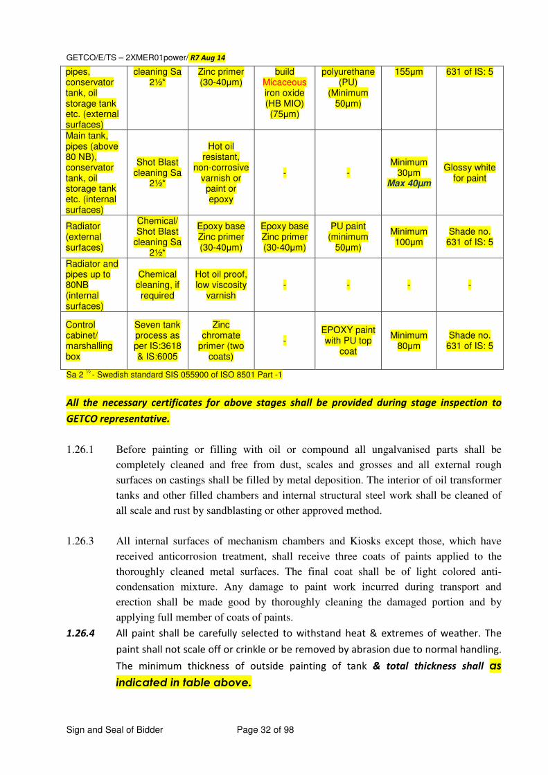
GETCO/E/TS – 2XMER01power/ R7 Aug 14
Sign and Seal of Bidder Page 32 of 98
pipes, conservator tank, oil storage tank etc. (external surfaces)
cleaning Sa 2½*
Zinc primer (30-40μm)
build Micaceous iron oxide (HB MIO) (75μm)
polyurethane (PU)
(Minimum 50μm)
155μm 631 of IS: 5
Main tank, pipes (above 80 NB), conservator tank, oil storage tank etc. (internal surfaces)
Shot Blast cleaning Sa
2½*
Hot oil resistant,
non-corrosive varnish or paint or epoxy
- - Minimum
30μm Max 40µm
Glossy white for paint
Radiator (external surfaces)
Chemical/ Shot Blast
cleaning Sa 2½*
Epoxy base Zinc primer (30-40μm)
Epoxy base Zinc primer (30-40μm)
PU paint (minimum
50μm)
Minimum 100μm
Shade no. 631 of IS: 5
Radiator and pipes up to 80NB (internal surfaces)
Chemical cleaning, if required
Hot oil proof, low viscosity
varnish - - - -
Control cabinet/ marshalling box
Seven tank process as per IS:3618 & IS:6005
Zinc chromate
primer (two coats)
- EPOXY paint with PU top
coat
Minimum 80μm
Shade no. 631 of IS: 5
Sa 2 ½
- Swedish standard SIS 055900 of ISO 8501 Part -1
All the necessary certificates for above stages shall be provided during stage inspection to
GETCO representative.
1.26.1 Before painting or filling with oil or compound all ungalvanised parts shall be
completely cleaned and free from dust, scales and grosses and all external rough
surfaces on castings shall be filled by metal deposition. The interior of oil transformer
tanks and other filled chambers and internal structural steel work shall be cleaned of
all scale and rust by sandblasting or other approved method.
1.26.3 All internal surfaces of mechanism chambers and Kiosks except those, which have
received anticorrosion treatment, shall receive three coats of paints applied to the
thoroughly cleaned metal surfaces. The final coat shall be of light colored anti-
condensation mixture. Any damage to paint work incurred during transport and
erection shall be made good by thoroughly cleaning the damaged portion and by
applying full member of coats of paints.
1.26.4 All paint shall be carefully selected to withstand heat & extremes of weather. The
paint shall not scale off or crinkle or be removed by abrasion due to normal handling.
The minimum thickness of outside painting of tank & total thickness shall as
indicated in table above.
GETCO/E/TS – 2XMER01power/ R7 Aug 14
Sign and Seal of Bidder Page 33 of 98
1.27 PACKING AND TRANSPORT: 1.27.1 Transportation: The bidder shall dispatch the transformer filled with oil or in an atmosphere of
Nitrogen or dry air. In the former case the bidder shall take care of the weight limitation on transport and handling facility at site. In the latter case, necessary arrangement shall be ensured by the bidder to take care of pressure drop of Nitrogen or dry air during transit and storage till completion of oil filling during erection. A gas pressure testing valve with necessary pressure gauge and adaptor valve shall be provided. The transformer shall be fitted with sufficient number of impact recorders during transportation to measure the movement due to impact in all three directions. The impact recorder shall be provided with suitable communication port (USB port) to
down load data at any time. The impact recorder shall be returned after submission of all
the data in hard and soft copy.
1.27.2 All parts shall be adequately marked to facilitate field erection.
1.27.3 In case of synthetic resin bonded paper type bushing is offered; special attention shall be paid in packing so as to avoid moisture ingress. The details of the bushing and the method of packing shall be stated in the bid.
1.27.4 Loose Material e.g. bolts nuts etc. shall be packed in gunny bags and sealed in polyethylene bags with proper tagging. Component containing glass shall be carefully covered with shock absorbing protective material. All flanges etc. which are prone to scratches shall be provided with wooden caps bolted in place. Fragile Material shall be securely braced within the containers or otherwise amply fastened and packed to prevent shifting or rattling. Soft non-hydroscopic packing materials shall be placed between hard packing Materials and fragile equipment. Articles which do not completely filled the selected container must be cushioned, braced, fastened or blocked to prevent damage to the article itself of destruction of container. Inner bracing or blocking must be such that content’s weight is distributed over entire interior surface rather than concentrate on one or two critical points. All opening in the equipment / accessories shall be tightly covered, plugged or capped to prevent foreign material to enter in.
1.27.5 Any material found short / damaged inside the intact packing shall be supplied at no extra cost to the purchaser.
1.28 LABELS: 1.28.1 Labels shall be provided for all apparatus such as relays, switches, fuses contained in
cubicles or marshalling kiosk. 1.28.2 Labeling shall be clear, concise and adequate and shall be of standard size. 1.28.3 Descriptive labels for mounting indoor or inside cubicles and kiosk shall be of material
that will ensure permanence of the lettering. Danger notices shall have red lettering on a white background. All plates shall be of material, which will not be corroded.
1.28.4 Labels shall be attached to panels with brass screws or with steel screws, which have
received rust preventive treatment.
GETCO/E/TS – 2XMER01power/ R7 Aug 14
Sign and Seal of Bidder Page 34 of 98
1.29 INSPECTION:
(a) The bidder shall carry out a detailed inspection and testing program for
manufacturing activities of the various components. An indicative program of
inspection of as envisaged by the Engineer is given below. This is not,
however, intended to form a comprehensive program as it is bidder’s
responsibility to draw up and carry out such a program duly approved by the
Engineer.
(b) Cost of inspection/tests is to be borne by the bidder.
(c) Additional tests, if required, are to be deemed as included in scope of work.
(d) Stages of inspection and owners participation would be defined and shall
be as per purchaser requirement. Photographs shall be taken jointly
and submitted with inspection report. (e) The bidder shall guarantee that the goods are new and of high quality and the
goods will be free from defects in design.
TANK AND CONSERVATOR:
(a) Certificates of chemical analysis and material tests of plates.
(b) Welder’s and weld procedure qualification.
(c) Testing of electrodes for quality of base material.
(d) Inspections of major weld preparation.
(e) Crack detection of major strength weld seam by dye penetration test.
(f) Measurement of film thickness of
i) Oil insoluble varnish.
ii) Total paint thickness
iii) Light gray paint.
(g) Check correct dimensions between wheels, demonstrate twining of wheels
through 900 and further dimensional check.
(h) Check for physical properties of materials for lifting lugs jacking pad etc. All
load bearing welds including lifting lug welds shall be subjected to NDT.
(i) Leakage test of the conservator.
(j) Certification of all test results.
CORE:
(a) Samples testing of core material for checking specific loss, bend properties
magnetization characteristics and thickness.
(b) Check on the quality of varnish if used on the stampings.
(c) (i) Measurement of thickness & hardness of varnish on the stampings.
(ii) Solvent resistance test to check that varnish does not react in hot oil.
GETCO/E/TS – 2XMER01power/ R7 Aug 14
Sign and Seal of Bidder Page 35 of 98
(iii) Check over all quality of varnish on stamping to ensure uniform shining
colour, no bars spots, no over burnt varnish layer and no bubbles on
varnished surface.
(d) Check on the amount of burrs.
(e) Bow check on stampings.
(f) Check for the overlapping stampings, Corners of the sheets are to be apart.
(g) Visual and dimensional check during assembly stage.
(h) Check for inter laminar insulation between core sections before & after
pressing.
(i) Check on completed core for measurement of iron loss and check for any hot
spot by exciting the core so as to induce the designed value of flux density in
the core. The losses shall be actually measured on built up core with
dummy turns or can be demonstrated through suitable software to
GETCO representative and the report for the same shall be submitted.
However, during final inspection the losses shall be actually measured
& the same shall be within guaranteed losses.
(j) Visual and dimensional checks for straightness and roundness of core,
thickness of limbs and suitability of clamps.
(k) High voltage test (2 KV for one minute) between core and clamps.
(l) Certification of all test results.
INSULATING MATERIAL:
(a) Sample check for physical properties of material.
(b) Check for dielectric strength.
(c) Visual & dimensional checks.
(d) Sample check on insulating paper for pH Value, electric strength.
(e) Check for the reaction of hot oil on insulating materials.
(f) Certification of all tests results.
WINDING:
(a) Sample check on winding conductor for mechanical properties and electrical
conductivity.
(b) Visual dimensional checks on conductor for scratches, dent marks etc.
(c) Sample check on insulating paper for pH Value, electric strength.
(d) Check for the reaction of hot oil on insulating paper.
(e) Check for the bonding of the insulating paper on conductor.
(f) Check for absence of short circuit between parallel strands.
(g) Check and ensure that physical condition of all materials taken for winding is
satisfactory and free of dust.
(h) Check for brazed joints wherever applicable.
(i) Measurement of voltage to be carried out when core/yoke is completely
restacked and all connections ready.
GETCO/E/TS – 2XMER01power/ R7 Aug 14
Sign and Seal of Bidder Page 36 of 98
(j) Conductor enamel test for checking of cracks, leakage and pin holes
(k) Conductor flexibility test
(l) Heat Shrinkable test for enameled wire
(m) Certification of all test results
CHECK BEFORE DRYING PROCESS:
(a) Cheek conditions of insulation in the conductor and between the windings.
(b) Cheek insulation resistance between high voltage connection cable and earth
others live parts.
(c) Check insulation resistance between low voltage connection and earth & other
parts.
(d) Insulation test of core earthing.
(e) Check for proper clean lines and absence of dust etc.
(f) Certification of all test results.
CHECK DURING DRYING PROCESS:
a) Measurement and recording of temperature and drying time during vacuum
treatment.
b) Check for completeness of drying.
c) Certification of all test results.
ASSEMBLED TRANSFORMER:
(a) Check completed transformer against approved outline drawing: provision for
all fitting, finish level etc.
(b) Taking test on all the assembled transformer
The bidder shall also prepare a comprehensive inspection and testing program
for all bought out / sub-contracted items and shall submit the same to the
Engineer for approval. Such program shall include the following.
(i) Buchholz relay
(ii) Sudden/rapid pressure rise relay/ PRV
(iii) Axles and wheels.
(iv) Winding temperature indicator for local and remote mounting.
(v) Oil temperature indicators
(vi) Bushing
(vii) Bushing Current Transformer
(viii) Terminal connectors (ix) Radiators, cooler control and any other item, as desired by purchaser.
c) Test to check effective shielding of the tank d) Jacking test with oil on all the assembled transformers e) Dye penetration test shall be carried out after the jacking test
PRE-SHIPMENT CHECKS AT MANUFACTURER’S WORKS:
(a) Check for interchangeability of components of similar transformer for
mounting dimensions.
(b) Check for proper packing and preservation of accessories like radiators,
bushings, PRV, dehydrating breather, rollers, Buchholz relay, control cubicle,
connecting pipes, conservator tank. (c) Check for proper provision of bracings to arrest the movement of core and
winding assembly inside the tank.
GETCO/E/TS – 2XMER01power/ R7 Aug 14
Sign and Seal of Bidder Page 37 of 98
(d) Gas tightness test to conform tightness. (e) Derivation of leakage rate and ensure adequate reserve gas capacity.
INSPECTION AND TESTING AT SITE:
The successful bidder shall carry out a detailed inspection and testing program for
field activities, namely covering area right from the receipt of material stage up to
commissioning stage. An indicative program of inspection as envisaged by the
Engineer is given below.
This is however not intended to form a comprehensive program as it is bidder’s
responsibility to draw up and carry out such a program duly approved by the Engineer.
1.30 RECEIPT AND STORAGE CHECKS:
(a) Check and record condition of each package, visible part of the transformer
etc. for any damage.
(b) Check and record the gas pressure in the transformer tank as well as in the
cylinder.
(c) Visual check for welding of core and coils before filling up with oil and also
check condition of core and winding in general.
1.30.1 INSTALLATION CHECKS:
Test on oil samples taken from main tank top and bottom and cooling system as per
IS:335. Sample should be taken only after the oil has been allowed to settle for 24
hours.
1.30.1.1 Check the whole assembly for tightness, general appearance, etc.
1.30.1.2 Oil leakage tests.
1.30.1.3 The bidder shall warrant that oil furnished is in accordance will the specifications
given in this specification. 1.30.1.4 Capacitance and tan delta measurement of bushings before fixing / connecting to the
winding. Bidder shall furnish these values for site reference. 1.30.1.5 Sweep Frequency Response Analysis (SFRA) test
1.30.2 COMMISSIONING CHECKS:
(a) Check the color of silica gel breather.
(b) Check the oil level in the breather housing conservator tank, cooling system,
condenser bushing etc.
(c) Check the bushings for conformity of connection to the line etc.
(d) Check for correct operation of all protections and alarms :
(i) Buchholz relay
(ii) Excessive winding temperature
(iii) Low oil flow
(iv) Excessive oil temperature
(v) Low oil level indication
(e) Check for adequate protection on electronic circuit supplying the accessories.
(f) Insulation Resistance measurement for
(i) Control wiring
(ii) Main winding
(g) Check for cleanliness of the transformer and the surrounding.
GETCO/E/TS – 2XMER01power/ R7 Aug 14
Sign and Seal of Bidder Page 38 of 98
1.30.3 TESTING:
1.30.3.1 The transformer shall be tested in the presence of GETCO’s representative; all tests
(routine and type tests) shall be witnesses by him. All the tests shall be performed in
compliance of IS:2026-1962 (as amended up to date). All the instruments, meters, instrument transformers etc., used for testing shall be duly calibrated
at NABL laboratory and necessary calibration certificate shall be made available during inspection. The instrument transformers shall have ≤0.2 accuracy
class. The measurement of losses shall be carried out with 3 (Three) Watt meter method
only through digital power analyzer and CTs, PTs and meters used for these measurements
shall be of class of accuracy of 0.2. The following tests shall be carried out on the
transformer.
1.30.3.1(a) ROUTINE TESTS:
All the tests shall be performed in compliance of IS:2026 (as amended up to date)
with dielectric tests corresponding to Method 2 shall be carried out on each
transformer:
(a) Resistance of each winding.
(b) Turns ratio for all sets of windings on each tap, with percentage error.
(c) Polarity and phase relation-ship.
(d) Impedance between each pair of winding.
(e) Excitation losses at 90, 100 and 110 % rated voltage measured by the average
voltmeter method.
(f) Positive phase sequence impedance measurement on three phase transformers.
(g) Regulation at rated load and unity, 0.9, 0.8 lagging P.F.
(h) Load losses, measured at rated frequency, by applying a primary voltage
sufficient to produce rated current in the windings with the secondary windings
short-circuited.
(i) Separate source voltage withstand test.
(j) ACLD test (k) Auxiliary losses (fans, pump, etc)
(l) SFRA test (at factory and at site)
(m) Zero Sequence impedance test
(n) Tests on tap-changer (IEC:60214)
(o) Tan delta & capacitance test for bushings and windings
(p) Tests on transformer oil including DGA on selected sample as per
IS:9434/IEC: 567, before and after temp rise test and at final stage before
dispatch. Corrosive sulphur detection test as per IEC 62535
subjecting oil for 150oC for 72 hrs, as specified in Appendix – A
(Revised).
(q) Magnetic Circuit test:
After assembly of each core shall be tested at 2 kV between side plates,
structural steel works etc. for 1 Minute
(r) Tank leak test at 5 psi (35 kN/m2) for 12 hrs with oil & 1 hr with air.
(s) Magnetic Balance & current test on all winding
(t) HV withstand test on auxiliary equipments and wiring
(u) Measurement of Insulation Resistance
(v) Measurement of acoustic noise level
(w) Measurement of harmonics of no load current
GETCO/E/TS – 2XMER01power/ R7 Aug 14
Sign and Seal of Bidder Page 39 of 98
(x) Measurement of Partial Discharges of transformer
(y) Vacuum test for tank at 25 bar for 1 hr.
(z) Measurement of no load current with 415 V AC supply on LV side. (aa) Tests on air cell
(bb) Temperature rise as per cl. 1.30.3.1(b)(i) with DGA at initial, after Temp
rise test and at final stage before dispatch.
(cc) Lightning impulse test on all windings
(dd) Water content in transformer measurement test (limit – 0.5% - 0.7% of total
insulation weight) – By Karl Fischer method. Sample shall be decided jointly.
(ee) Measurement of transferred surge in LV due to Lighting impulse on HV
(ff) Tests on Fiber Optic system viz. (i) Calibration (ii) functionality and conformance tests
along with test report for Probe dielectric test”
(gg) Calibration of temperature indicators and relays.
(hh) CT testing viz. IR, ratio, polarity, excitation etc.
(ii) OLTC Motor current signature
(jj) Transferred surge test on LV due to HV.
All the routine/acceptance tests shall be carried out on transformer filled with oil and fitted with all accessories to be supplied with transformer.
1.30.3.1(b) TYPE TEST:
Following type test reports as specified in IS: 2026 (amended up to date) shall be
submitted for the offered type rating of transformer, invariably with the technical bid.
Bid without type test reports will not be considered for evaluation. The type test
reports shall not be older than FIVE years and shall be valid up to expiry of validity of
offer.
i) Temperature rise test
The temperature rise test shall be conducted at a tap for the worst combination of
loading i.e. Load losses measured at minimum voltage tap and no load losses
measured at rated voltage. The thermometers used during test shall be digital
having calibrated in NABL lab. Calibration certificate shall not be older than one
year.
Gas chromatographic analysis on oil shall also be conducted before and after this test
and the values shall be recorded in the test report. The sampling shall be in
accordance with IEC 60567. For the evaluation of the gas analysis in temperature rise
test the procedure shall be as per IS: 9434 (based on IEC 60567) and results will be
interpreted as per IS: 10593 (based on IEC: 60599). The temperature rise
measurements shall be made with the Fiber Optic Thermometers & conventional
OTI/WTI. The FOS shall also be operational during temperature tests and
demonstrated during these tests. During probe verification, the hottest probes for
each phase shall be identified, and temperature data for all probes recorded and
reported in the test report. Data obtained from FOS and conventional OTI/WTI shall
be compared however, both values should satisfy the commitment.
ii) Impulse test shall be made on three limbs of transformer. The test sequence
shall be with chopped wave.
GETCO/E/TS – 2XMER01power/ R7 Aug 14
Sign and Seal of Bidder Page 40 of 98
iii) Vacuum and pressure test
iv) Tests on OLTC
Important note for type tests: The type test report shall be submitted for the offered class and
rating of transformer. However, the type test report for higher class/rating can be accepted for
scrutiny of technical bid but the same test/s shall have to be carried out on the offered
class/rating transformer. Bidder shall invariably confirm to carry out the required type test/s,
special tests, before commencement of supply, without affecting delivery schedule, free of cost,
at NABL approved laboratory, or at suppliers works in presence of NABL &/OR GETCO
representatives, in the event of order.
1.30.3.1(c) SPECIAL TESTS:
Following test reports shall be submitted for the offered type rating of
transformer & bought outs, invariably with the technical bid.
i) Zero phase sequence impedance measurement.
ii) Degree of protection (IP55) for control cabinets, OLTC driving mechanism,
terminal boxes of PRV, MOG, Buchholz Relay, pump motors, fans, control
cubicles for monitoring and NIFPS, etc. RTCC panel shall have IP 54 degree
protection
iii) Short Time Current withstand test on offered HV and LV terminal connectors for
40 kA 3 sec.
iv) Measurement of acoustic noise level
v) Measurement of power taken by all auxiliaries
vi) Measurement of harmonic level in no load current
vii) Measurement of transferred surge in LV due to Lighting impulse on HV & IV
viii) ACLD test
If the above tests are carried out at bidder works then the bidder shall have to repeat these tests
again on any one unit without affecting delivery schedule at no extra cost to GETCO. The
necessary confirmation shall invariably be submitted with the technical bid otherwise the offer
shall be evaluated accordingly.
1.30.3.1(d) CALCULATIONS:
i) Thermal and Dynamic ability to withstand terminal short circuits
ii) Cooling calculations for ONAN, ONAF & OFAF.
iii) Calculation of offered losses with respect to offered winding and core materials.
1.30.3.2 Radiator, valves and other parts necessary for complete transformer shall be tested
for leaks and strength applying to the complete tank filled with oil by air pressure not
less than 0.7 atmospheres for a period of 24 hours or not less than 1.0 atmosphere for
a period of 6 hours.
1.30.3 TESTS ON TRANSFORMERS TANK:
In addition to the routine tests on welds in the tank, the following type tests shall be
carried out on one of the transformer tanks in presence of GETCO representative.
1.30.3.1 VACUUM TEST:
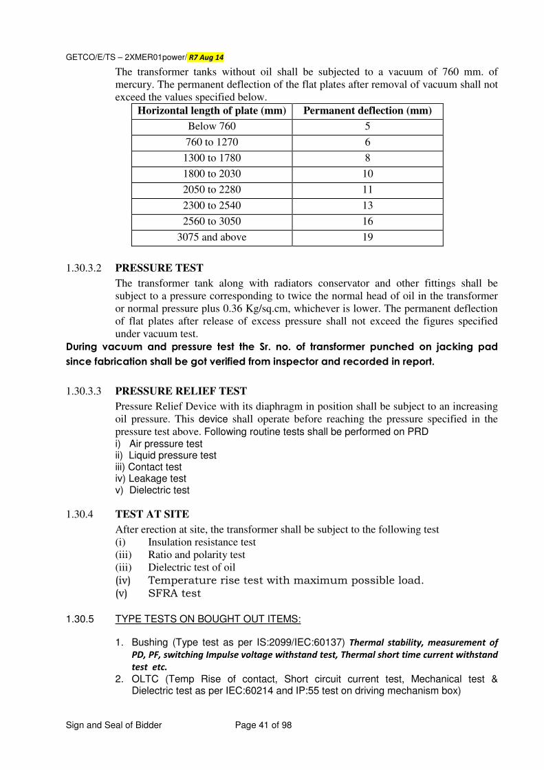
GETCO/E/TS – 2XMER01power/ R7 Aug 14
Sign and Seal of Bidder Page 41 of 98
The transformer tanks without oil shall be subjected to a vacuum of 760 mm. of
mercury. The permanent deflection of the flat plates after removal of vacuum shall not
exceed the values specified below.
Horizontal length of plate (mm) Permanent deflection (mm)
Below 760 5
760 to 1270 6
1300 to 1780 8
1800 to 2030 10
2050 to 2280 11
2300 to 2540 13
2560 to 3050 16
3075 and above 19
1.30.3.2 PRESSURE TEST
The transformer tank along with radiators conservator and other fittings shall be
subject to a pressure corresponding to twice the normal head of oil in the transformer
or normal pressure plus 0.36 Kg/sq.cm, whichever is lower. The permanent deflection
of flat plates after release of excess pressure shall not exceed the figures specified
under vacuum test.
During vacuum and pressure test the Sr. no. of transformer punched on jacking pad
since fabrication shall be got verified from inspector and recorded in report.
1.30.3.3 PRESSURE RELIEF TEST
Pressure Relief Device with its diaphragm in position shall be subject to an increasing
oil pressure. This device shall operate before reaching the pressure specified in the
pressure test above. Following routine tests shall be performed on PRD i) Air pressure test ii) Liquid pressure test iii) Contact test iv) Leakage test v) Dielectric test
1.30.4 TEST AT SITE
After erection at site, the transformer shall be subject to the following test
(i) Insulation resistance test
(iii) Ratio and polarity test
(iii) Dielectric test of oil
(iv) Temperature rise test with maximum possible load. (v) SFRA test
1.30.5 TYPE TESTS ON BOUGHT OUT ITEMS:
1. Bushing (Type test as per IS:2099/IEC:60137) Thermal stability, measurement of
PD, PF, switching Impulse voltage withstand test, Thermal short time current withstand
test etc.
2. OLTC (Temp Rise of contact, Short circuit current test, Mechanical test & Dielectric test as per IEC:60214 and IP:55 test on driving mechanism box)
GETCO/E/TS – 2XMER01power/ R7 Aug 14
Sign and Seal of Bidder Page 42 of 98
3. Buchholz relay (as per IS:3637) & IP-55 on terminal box 4. Air cell (Flexible air separator) – Oil side coating, Air side under coating, Air side
outer coating and coated fabric as per IS:3400/BS:903/IS:7016. 5. Oil pump – vacuum test, oil pressure test at 1 kg/cm2 for 24 hrs., Temperature
rise test by resistance method, IP-55 for terminal box. 6. Cooling fan and motor assembly – Free air delivery, Temperature rise, sound
level, running at reduced voltage, IP-55 for terminal box. 7. MOG & terminal box for IP-55 degree of protection 8. Tests on fiber optic system- (i) Full wave negative impulse & Negative switching surge
tests as per ASTM D-3426 and (ii)PD as per ASTM D-149 tests on fiber optic cable along
with EMC testing : Surge testing 4000V (IEEE C37.90.1-2002) on measuring instrument ”
9. For any other item required during detailed engineering.
10. Tests on AVR relay – Electrical, Environmental & Mechanical test as per relevant IEC
and compatibility with IEC 61850.
1.31 TESTS ON OLTC:
1.31.1 The various tests (routine and type) as stipulated in the IEC:60214 (as amended up to-
date) including vacuum helium and gas leak tests shall be carried out.
1.31.2 Type test certificate copies of oscillograms as called for in IEC:60214 (as amended up
to-date)shall be furnished by the supplier.
1.32 TEST REPORTS:
1.32.1 On completion of all the tests have been completed 3 copies of each test report shall be
furnished to the GETCO for his approval prior to the dispatch of equipment. Soft copy of test reports for tests results obtained from software shall be submitted for approval and record.
1.32.2 All the reports of inspections like stage, acceptance, routine & type tests carried out
on each transformer including test certificates for bought out items, in bound
volume, shall be submitted before dispatch. Also one copy shall be sent along with
transformer.
1.33 FURTHER TESTS:
The GETCO reserves the right of having any other reasonable test carried out at his
own expense to ensure that the transformer compiled with requirements of this
specification.
1.34 LOSS/DAMAGES: 1.34.1 The Purchaser shall not be responsible for any damage to the equipment during
commissioning if such damage results from faulty or inadequate action. 1.34.2 Purchaser shall not be liable for any loss, damage or injury to property or persons at
the installation site unless such damages or injuries are caused by any and or negligence of the supervising erector.
1.35 TECHNICAL AND GUARANTEED PARTICULARS:
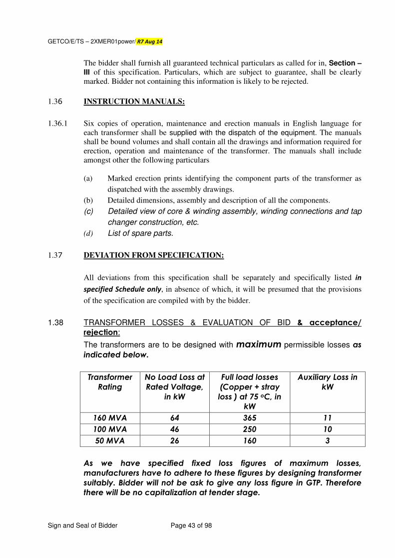
GETCO/E/TS – 2XMER01power/ R7 Aug 14
Sign and Seal of Bidder Page 43 of 98
The bidder shall furnish all guaranteed technical particulars as called for in, Section –
III of this specification. Particulars, which are subject to guarantee, shall be clearly
marked. Bidder not containing this information is likely to be rejected.
1.36 INSTRUCTION MANUALS:
1.36.1 Six copies of operation, maintenance and erection manuals in English language for
each transformer shall be supplied with the dispatch of the equipment. The manuals
shall be bound volumes and shall contain all the drawings and information required for
erection, operation and maintenance of the transformer. The manuals shall include
amongst other the following particulars
(a) Marked erection prints identifying the component parts of the transformer as
dispatched with the assembly drawings.
(b) Detailed dimensions, assembly and description of all the components.
(c) Detailed view of core & winding assembly, winding connections and tap
changer construction, etc.
(d) List of spare parts.
1.37 DEVIATION FROM SPECIFICATION:
All deviations from this specification shall be separately and specifically listed in
specified Schedule only, in absence of which, it will be presumed that the provisions
of the specification are compiled with by the bidder.
1.38 TRANSFORMER LOSSES & EVALUATION OF BID & acceptance/
rejection:
The transformers are to be designed with maximum permissible losses as
indicated below.
Transformer
Rating
No Load Loss at
Rated Voltage,
in kW
Full load losses
(Copper + stray
loss ) at 75 oC, in
kW
Auxiliary Loss in
kW
160 MVA 64 365 11
100 MVA 46 250 10
50 MVA 26 160 3
As we have specified fixed loss figures of maximum losses,
manufacturers have to adhere to these figures by designing transformer
suitably. Bidder will not be ask to give any loss figure in GTP. Therefore
there will be no capitalization at tender stage.
GETCO/E/TS – 2XMER01power/ R7 Aug 14
Sign and Seal of Bidder Page 44 of 98
The order will be placed to lowest price bidder as per GETCO policy
and actual losses measured during acceptance. It will be at discretion
of GETCO to accept/reject the unit whenever there is positive variation
in the losses measured at actual.
However, the unitunitunitunit shall not be accepted in the event measured losses
are beyond the following limits against the fixed loss figures specified in
the tender.
1) No Load losses : 5%
2) Full Load losses : 2%
3) Aux losses : 5%
Penalty towards the higher losses within above limits shall be recovered as follow:
1) No Load losses: 3 times capitalization cost of `̀̀̀ 3,33,000/- per kW
2) Full Load losses: 3 times capitalization cost of `̀̀̀ 1,36,000/- per kW
3) Aux losses: 3 times capitalization cost of `̀̀̀ 1,33,000/- per kW
It is also proposed that testing of unit will be carried out in presence and
witness of third party selected by GETCO at the discretion of GETCO.
In case of any order, the losses of successful bidder will be measured during acceptance
testing and if the figures of looses are found equal to or lesser than specified above, the
transformer shall be accepted. However, if any of the loss figure measured during
acceptance test is found more than specified above, the transformer will not be accepted.
There shall be no provision for penalty for acceptance of transformer with losses higher
than specified above. Bidder shall submit undertaking separately for the same, with the
technical bid. The measurement of losses shall be carried out with 3 (Three) Watt meter method only and CTs, PTs and meters used for these measurements shall be of class of accuracy of 0.2.
However, no weightage shall be given for supply of transformer, with losses (measured during routine tests) less than the above specified losses.
1.40 REJECTION:
1.40.1 The Purchaser shall reject transformer, if any of the following conditions during or service arises:
i) No load losses or load losses or Auxiliary losses exceed the d specified value.
ii) Impedance value deviates the guaranteed value by + 10% or more.
iii) Oil or winding temperature rise exceeds the specified value.
iv) Transformer fails to withstand any of the dielectric tests.
v) Transformer fails to pass any of acceptance test.
vi) Transformer is proved to have been manufactured not in accordance with agreed
specification.
1.40.2 The Purchaser reserves the right to retain the rejected transformer and use it until the
bidder replaces the defective transformer by a new transformer, as a stop gap
arrangement, within a reasonable period, at no extra costs to the GETCO.
GETCO/E/TS – 2XMER01power/ R7 Aug 14
Sign and Seal of Bidder Page 45 of 98
Defective transformer may be replaced by new acceptable transformer. In such case the transportation, loading, unloading on plinth, inspection, erection, testing & commissioning charges shall be bourn by the bidder.
1.41 TRAINING TO ENGINEERS:
1.41.1 The successful bidder will be required to grant facilities for training to minimum two
Engineers to be nominated by the GETCO, for accessories indicated in this specification.
Training in respect of Fiber Optic system, On line moisture and multi gas in oil analyzer,
Nitrogen injection system for protection, AVR relay, On line PD measurement,
GPS/GRPS/GSM based on line transformer movement tracking system on returnable basis,
Condition controlled maintenance free on line breather, etc., as applicable shall be arranged.
The bidder shall state the general condition of training and number of Man
days (minimum 15) for training for which such training will be arranged by him.
GETCO may nominate different Engineers for different items.
1.41.2 Bidder shall at his cost arrange for the above training facilities and in addition shall
bear all living expenses excluding to and fro passage of the trainees. Bidder shall
indicate following in the prices schedule.
a) The lump sum amount of training for the above training facilities.
b) Price reduction / addition for number of trainees specified herein.
1.42 Guarantee period will be reckoned from the date of receipt of 100 % accessories and
not from the date of receipt of main tank only.
1.43 If GETCO Engineer happens to return without inspection of offered equipments due to non-readiness of materials at their works then financial loss to the GETCO for deputing their representative will be recovered from the concerned supplier.
1.44 TRANSFORMER OIL:
1.44.1 (1) Manufacturers / Suppliers will have to supply the transformer oil as per GETCO’s
Specification of Transformer oil attached herewith at Annexure - A.
(2) At the time of inspection of transformer, bidder has to furnish the certificate / test reports of transformer oil purchased. Same should be meeting to GETCO’s transformer oil specification. At the time of inspection of the each power transformer, the supplier of the transformer shall arrange to take a sample of the transformer oil from the power transformer under testing in presence of GETCO’s representative and the supplier shall arrange at their cost the testing of the transformer oil sample as per Cl. 5.3 of IS: 1866 - 1994 with latest amendments thereof at M/s. ERDA or any other Govt. recognized laboratory to confirm the quality of the transformer oil. The result of the same shall be submitted for approval.
(3) After commissioning the transformer at site, in presence of representative,
commissioning Engineer of Supplier of transformer, 2 nos. of joint samples may be collected and sealed. One sample will be sent for testing as per Cl. 5.3 of IS: 1866 - 1994 with latest amendments thereof to M/s. ERDA, Baroda or
GETCO/E/TS – 2XMER01power/ R7 Aug 14
Sign and Seal of Bidder Page 46 of 98
Government approved Laboratory to confirm the quality of transformer oil and second sample will be preserved. In case of dispute for results of first sample, 2nd sample should be got tested through any other approved test house by GETCO and results shall be binding to suppliers.
1.45 QUALITY ASSURANCE PLAN:
The bidder shall invariably furnish following information's along with his
offer, failing which his offer shall be liable for rejection. Information shall
be separately given for individual type of equipments offered.
1. QAP for incoming material, in process and final checks and testing.
2. Statement giving list of important raw materials, names of sub
suppliers for the raw materials, list of standard according to which the
raw materials are tested. List of tests normally carried out on raw
materials in presence of bidder's representatives, copies of test
certificates.
3. Information and copies of test certificates as in (i) above in respect of
bought out accessories.
4. List of manufacturing facilities available.
5. Level of automation achieved and list of areas where manual
processing exists.
6. List of areas in manufacturing process, where stage inspections are
normally carried out for quality control and details of such tests and
inspections.
7. Special features provided in the equipment to make it maintenance
free.
8. List of testing equipments available with the supplier for final testing of
transformer specified and test plant limitation, if any, for the special
acceptance and routine tests specified in the relevant standards. These
limitations shall be very clearly brought out in 'The schedule of
divinations' for specified test requirements.
9. Field Quality Plan shall be submitted with the technical bid.
GETCO/E/TS – 2XMER01power/ R7 Aug 14
Sign and Seal of Bidder Page 47 of 98
SECTION – II
TECHNICAL SPECIFICATION FOR 220 kV CLASS POWER TRANSFORMERS
SPECIFIC REQUIREMENTS
2.1 SCOPE:
2.1.1 This section covers the specific technical requirements, climatic and isokeraunic conditions and system particulars for which the power transformer shall be offered as per the general technical requirements given in Section – I of this specification and the Schedule of requirements specified herein for the various sub-stations.
2.2 CLIMATIC AND ISOCERANIC CONDITIONS: 2.2.1 The climatic conditions under which the equipments shall operate satisfactorily.
(a) Maximum ambient temperature of air in Shade (OC) 50
(b) Minimum ambient temperature of air in shade. (OC) 3.5
(c) Maximum relative humidity (%) 95
(d) Average number of thunder storm (days/annum). 15
(e) Average number rain fail (cm) 150
(f) Maximum wind pressure (kg / m2) 150
(g) Height above monsoon level (mtr) Not exceeding 1000
(h) Climate: Moderately hot & humid tropical, conducive to rust & fungus
growth.
(i) Isokeraunic level 30
(j) Earth quake acceleration (g) 0.08X2
2.2.2 All equipments offered shall be suitable for continuous satisfactory operation at the
full rated capacity under the climatic conditions.
2.2.3 Since the sub-station may be near seashore or industrial area, the equipment offered
shall be suitable for heavily polluted atmosphere.
2.3 TYPE AND RATING:
2.3.1 The transformers shall be core or shell type construction, 3 phase, oil immersed,
ONAN/ONAF/OFAF with external radiators and shall be suitable for outdoor
services. The rating and the electrical characteristics of the transformers shall be as
under:
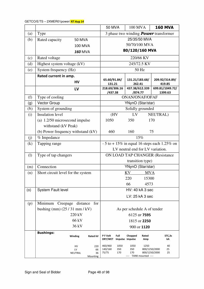
GETCO/E/TS – 2XMER01power/ R7 Aug 14
Sign and Seal of Bidder Page 48 of 98
50 MVA 100 MVA 160 MVA
(a) Type 3 phase two winding Power transformer
(b) Rated capacity 50 MVA
100 MVA
160 MVA
25/35/50 MVA
50/70/100 MVA
80/120/160 MVA
(c) Rated voltage 220/66 KV
(d) Highest system voltage (kV) 245/72.5 KV
(e) System frequency (Hz) 50 Hz
Rated current in amp.
HV
65.60/91.84/
131.21
131.21/183.68/
262.41
209.92/314.89/
419.85
LV 218.69/306.16
/437.38
437.38/612.339
/874.77
699.81/1049.72/
1399.63
(f) Type of cooling ONAN/ONAF/OFAF
(g) Vector Group YNynO (Star/star)
(h) System of grounding Solidly grounded
(i) Insulation level
(a) 1.2/50 microsecond impulse
withstand (kV Peak)
(b) Power frequency withstand (kV)
(HV LV NEUTRAL)
1050 350 170
460 160 75
(j) % Impedance 15%
(k) Tapping range - 5 to + 15% in equal 16 steps each 1.25% on
LV neutral end for LV variation.
(l) Type of tap changers ON LOAD TAP CHANGER (Resistance
transition type)
(m) Connection YNynO (Star/star)
(n) Short circuit level for the system KV MVA
220 15300
66 4573
(o) System Fault level HV: 40 kA 3 sec
LV: 25 kA 3 sec
(p) Minimum Creepage distance for
bushing (mm) (25 / 31 mm / kV)
220 kV
66 kV
36 kV
As per schedule A of tender
6125 or 7595
1815 or 2250
900 or 1120
Bushings: Winding Rated kV
HV 220
LV 66
NEUTRAL 36
Mounting
P F Volt Full Chopped Rated STC,3s
DRY/WET Impulse Impulse Amp kA
460/460 1050 1050 1250 40
140/160 350 350 800/1250/2000 25
75/75 170 170 800/1250/2000 25
---- TANK mounted ----
GETCO/E/TS – 2XMER01power/ R7 Aug 14
Sign and Seal of Bidder Page 49 of 98
(q) Service Outdoor
(r) Duty Continuous
(s) Overload capacity As per IS:6600 – 1972 / IEC354
(t) Partial Discharge level 100 Pico-coulomb, Max
2.3.2 The equipment offered shall be suitable for continuous operation under the above
conditions at the full rated capacity.
2.3.4 The power transformers shall in general have constant ohmic impedance between HV and LV on all taps. However, in case of parallel operation with the existing transformer, i) The impedance, vector group, OLTC connection & range etc. of the transformer is
to be matched with that of the existing transformer ii) Necessary provision is to be kept in the transformer control scheme for parallel
operation with the existing Master/Follower/Independent/Off type OLTC control system.
iii) Matching of physical dimension, orientation etc. to facilitate interchangeability with the existing transformer, if necessary.
2.3.4 External or internal reactors shall not be used to achieve the HV/LV impedance
specified
2.4 EARTHQUAKE & WIND DESIGN LOADS:
2.4.1 The equipment offered shall be designed to withstand repeated earthquake acceleration
of 0.08 x 2 g. and wind loads of 150 kg/m2 on the projected area non-simultaneous
without damage to component parts and without impairment or operation.
2.5 HV, LV AND NEUTRAL BUSHING CT:
2.5.1 One multi ratio, turret mounted type, current transformer shall be provided on all line
as well as common neutral lead in case of 2 winding transformer, neutral CT each for
H.V. & L.V with following technical details.
Voltage Class corresponding line voltage rating for line
bushing CT and corresponding neutral
voltage rating of neutral bushing CT
(A) HV side 160 & 100 MVA 50 MVA
(Line as well as neutral)
No. of cores ONE ONE
Ratio 900-1200/1 A 600-900/1 A
Accuracy class PS (As per IS: 2705)
Vk. ≥≥≥≥ 1400 V, at 1200A, 900 V at 900/1A
I0 at Vk/2 ≤≤≤≤ 30 ma
Application Restricted earth fault protection
GETCO/E/TS – 2XMER01power/ R7 Aug 14
Sign and Seal of Bidder Page 50 of 98
(B) LV side 160 MVA 100 MVA 50 MVA
(Line as well as neutral)
No. Of cores TWO or THREE (as indicated in Schedule – A of respective
tender)
Ratio 1200-1500/1A 900-1200/1A 600-900/1A
Accuracy class PS (As per IS: 2705)
Vk ≥≥≥≥ 1400 V, at 1200A, 900 V at 900/1A
I0 at Vk/2 ≤≤≤≤ 30 ma
Application Restricted earth fault protection
2.5.2 Any change in the parameters of CT required at the time of detailed engineering will
have to be incorporated without any extra cost. Turret mounted type, current
transformer shall be provided for each winding for WTI.
2.6 POWER SUPPLY FOR CONTROLS:
2.6.1 The AC power supply for auxiliaries will be available at 240 volts, 1 phase and 415V.
3 phase, 50 Hz. The frequency can vary between ± 3% of normal frequency of 50 Hz
and voltage can very from 85% to 110% of the normal value.
2.6.2 The D.C. supply at either 220 V or 110 Volts will be available from station battery.
The D.C. supply is subject to variation of ± 10%.
2.6.3 Each of the foregoing supplies will be made available by the purchaser at
one terminal for each transformer for operation of accessories & auxiliary
equipments. Bidder’s scope shall include distribution this point.
2.7 OIL STORAGE TANK: 2.7.1 General
This specification covers supply of oil storage tank of 15 cubic meter capacity along
with complete accessories. Number of tanks, if required, will be as indicated
in Schedule – A of respective tender.
2.7.2 Standard
The oil storage tank shall be designed and fabricated as per relevant Indian
Standards e.g. IS: 803 or other internationally acceptable standards.
2.7.3 Specifications
Transformer oil storage tanks shall be towable & rested on pneumatic types of
adequate quality & size. The tank shall be to cylindrical shape & mounted horizontally
and made of mild steel plate of adequate thickness. Size of the storage tank shall be
follows:
Diameter : 2.5 meter / suitable
Capacity : 15 cubic meters
GETCO/E/TS – 2XMER01power/ R7 Aug 14
Sign and Seal of Bidder Page 51 of 98
The tank shall be designed for storage of oil at a temperature of 100ºC.
2.7.3.1 The Bidder may further note that maximum height of any part of the complete
assembly of the storage tank shall not exceed 4.0 meters above road top.
2.7.3.2 The tank shall have adequate number of jacking pad so that it can be kept on jack
while completely filled with oil. The tank shall be provided with suitable saddles so
that tank can be rested on ground after removing the pneumatic tyres. Sr. no. of
transformer shall be punched on jacking pad since fabrication.
2.7.3.3 The tank shall be also fitted with manhole, outside & inside access ladder, silica gel
breather assembly, inlet & outlet valve, oil sampling valve with suitable adopter, oil
drainage valve, air vent etc. Pulling hook on both ends of the tank shall be provided
so that the tank can be pulled from either end while completely filled with oil. Bidder
shall indicate the engine capacity in horse power to pull one tank completely fitted
with oil. Oil level indicator shall be provided with calibration in terms of litre so that at
any time operator can have an idea of oil in the tank. Four nos. suitable rubber hoses
with couplers and unions each not less than 10 meter long shall also be provided.
2.7.3.4 The internal & external surfaces to be painted shall be short or sand blasted to
remove all rust and scale of foreign adhering matter or grease. All steel surfaces in
contact with insulating oil shall have painted with two coats of heat & oil resistant anti-
corrosive paint after one coat of red oxide as per IS:104 and one each coat of
finishing coats of glossy white shade.
All steel surfaces exposed to weather shall be given primary coat zinc chromate,
second coat of oil & weather resistant paint of a colour distinct from primary and final
two coats of glossy oil & weather resistant light grey paint in accordance with shade
no. 631 of IS: 5. All paint shall be carefully selected to withstand heat & extremes of
weather. The paint shall not scale off or crinkle or be removed by abrasion due to
normal handling. The minimum thickness of outside painting of tank shall be 20
microns per coat the total thickness shall be within 70 to 100 microns.
2.7.3.5 The tank shall contain a self mounted centrifugal oil pump with inlet and outlet valves,
with couplers suitable for rubber houses and necessary switchgear for its control.
There shall be no rigid connection to the pump. The pump shall be electrical motor
driven and shall have a discharge of not less than 6 klph with a discharge head of 8
Mtr. The pump motor and the control cabinet shall be enclosed in cubicle with IP55
enclosure.
2.8 OIL SAMPLING BOTTLE:
2.8.1 Oil sampling bottle shall be suitable for collecting oil sample from transformer and
shunt reactors for dissolved gas analysis. Bottles shall be robust enough so that no
damage occurs during frequent transportation of samples.
2.8.2 Oil sampling bottle shall be made of Stainless Steel having capacity of ONE litre.
GETCO/E/TS – 2XMER01power/ R7 Aug 14
Sign and Seal of Bidder Page 52 of 98
2.8.3 Oil sampling bottle shall be capable of being sealed gas tight and shall be fitted with
cocks on both ends.
2.8.4 The design of bottle & seal shall be such that loss of hydrogen shall not exceed 5%
per week.
2.8.5 An impermeable oil proof transparent plastic or rubber tube of about 5 mm diameter
and of sufficient length shall also be provide with each bottle along with suitable
connectors to fit the tube on to the oil sampling valves of the equipment and the oil
collecting bottle respectively.
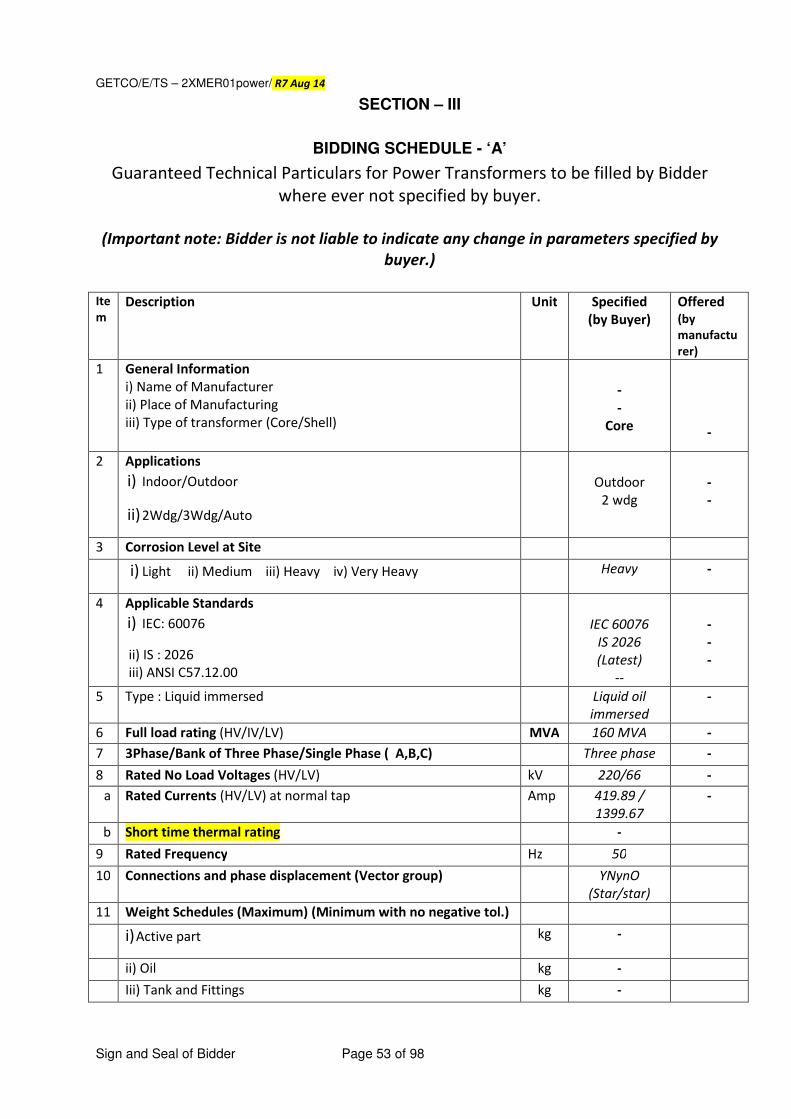
GETCO/E/TS – 2XMER01power/ R7 Aug 14
Sign and Seal of Bidder Page 53 of 98
SECTION – III
BIDDING SCHEDULE - ‘A’
Guaranteed Technical Particulars for Power Transformers to be filled by Bidder
where ever not specified by buyer.
(Important note: Bidder is not liable to indicate any change in parameters specified by
buyer.)
Ite
m
Description Unit Specified (by Buyer)
Offered
(by
manufactu
rer) 1 General Information
i) Name of Manufacturer ii) Place of Manufacturing iii) Type of transformer (Core/Shell)
- -
Core
-
2 Applications
i) Indoor/Outdoor
ii) 2Wdg/3Wdg/Auto
Outdoor
2 wdg
- -
3 Corrosion Level at Site
i) Light ii) Medium iii) Heavy iv) Very Heavy Heavy -
4 Applicable Standards
i) IEC: 60076
ii) IS : 2026 iii) ANSI C57.12.00
IEC 60076
IS 2026
(Latest) --
- - -
5 Type : Liquid immersed Liquid oil
immersed -
6 Full load rating (HV/IV/LV) MVA 160 MVA -
7 3Phase/Bank of Three Phase/Single Phase ( A,B,C) Three phase -
8 Rated No Load Voltages (HV/LV) kV 220/66 -
a Rated Currents (HV/LV) at normal tap Amp 419.89 /
1399.67 -
b Short time thermal rating - 9 Rated Frequency Hz 50 10 Connections and phase displacement (Vector group) YNynO
(Star/star)
11 Weight Schedules (Maximum) (Minimum with no negative tol.) i) Active part kg -
ii) Oil kg - Iii) Tank and Fittings kg -
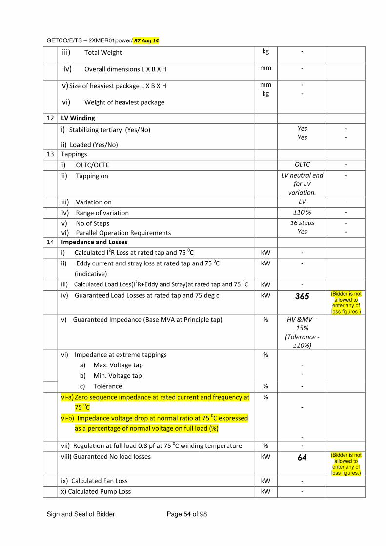
GETCO/E/TS – 2XMER01power/ R7 Aug 14
Sign and Seal of Bidder Page 54 of 98
iii) Total Weight kg -
iv) Overall dimensions L X B X H mm -
v) Size of heaviest package L X B X H
vi) Weight of heaviest package
mm kg
- -
12 LV Winding
i) Stabilizing tertiary (Yes/No)
ii) Loaded (Yes/No)
Yes Yes
- -
13 Tappings
i) OLTC/OCTC OLTC -
ii) Tapping on LV neutral end
for LV
variation.
-
iii) Variation on LV -
iv) Range of variation ±10 % -
v) No of Steps
vi) Parallel Operation Requirements 16 steps
Yes - -
14 Impedance and Losses i) Calculated I
2R Loss at rated tap and 75
0C kW -
ii) Eddy current and stray loss at rated tap and 75 0C
(indicative)
kW -
iii) Calculated Load Loss(I2R+Eddy and Stray)at rated tap and 75
0C kW -
iv) Guaranteed Load Losses at rated tap and 75 deg c kW 365 (Bidder is not allowed to
enter any of loss figures.)
v) Guaranteed Impedance (Base MVA at Principle tap) % HV &MV -
15%
(Tolerance -
±10%)
vi) Impedance at extreme tappings
a) Max. Voltage tap
b) Min. Voltage tap
% - -
c) Tolerance % -
vi-a) Zero sequence impedance at rated current and frequency at
75 0C
vi-b) Impedance voltage drop at normal ratio at 75 0C expressed
as a percentage of normal voltage on full load (%)
% -
-
vii) Regulation at full load 0.8 pf at 75 0C winding temperature % -
viii) Guaranteed No load losses kW 64 (Bidder is not allowed to
enter any of loss figures.)
ix) Calculated Fan Loss kW -
x) Calculated Pump Loss kW -
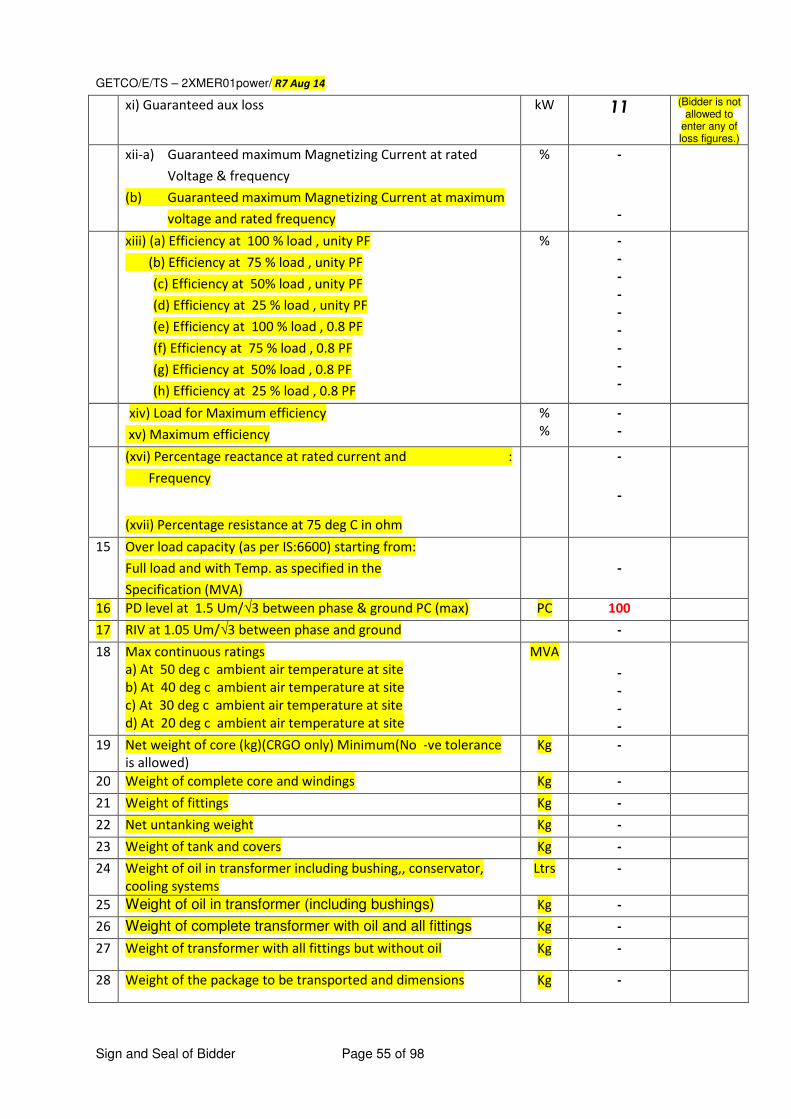
GETCO/E/TS – 2XMER01power/ R7 Aug 14
Sign and Seal of Bidder Page 55 of 98
xi) Guaranteed aux loss kW 11 (Bidder is not allowed to
enter any of loss figures.)
xii-a) Guaranteed maximum Magnetizing Current at rated
Voltage & frequency
(b) Guaranteed maximum Magnetizing Current at maximum
voltage and rated frequency
% -
-
xiii) (a) Efficiency at 100 % load , unity PF
(b) Efficiency at 75 % load , unity PF
(c) Efficiency at 50% load , unity PF
(d) Efficiency at 25 % load , unity PF
(e) Efficiency at 100 % load , 0.8 PF
(f) Efficiency at 75 % load , 0.8 PF
(g) Efficiency at 50% load , 0.8 PF
(h) Efficiency at 25 % load , 0.8 PF
% - - - - - - - - -
xiv) Load for Maximum efficiency
xv) Maximum efficiency
% %
- -
(xvi) Percentage reactance at rated current and :
Frequency
(xvii) Percentage resistance at 75 deg C in ohm
-
-
15 Over load capacity (as per IS:6600) starting from:
Full load and with Temp. as specified in the
Specification (MVA)
-
16 PD level at 1.5 Um/√3 between phase & ground PC (max) PC 100 17 RIV at 1.05 Um/√3 between phase and ground - 18 Max continuous ratings
a) At 50 deg c ambient air temperature at site b) At 40 deg c ambient air temperature at site c) At 30 deg c ambient air temperature at site d) At 20 deg c ambient air temperature at site
MVA - - - -
19 Net weight of core (kg)(CRGO only) Minimum(No -ve tolerance
is allowed) Kg -
20 Weight of complete core and windings Kg - 21 Weight of fittings Kg - 22 Net untanking weight Kg - 23 Weight of tank and covers Kg - 24 Weight of oil in transformer including bushing,, conservator,
cooling systems Ltrs -
25 Weight of oil in transformer (including bushings) Kg - 26 Weight of complete transformer with oil and all fittings Kg - 27 Weight of transformer with all fittings but without oil Kg -
28 Weight of the package to be transported and dimensions Kg -
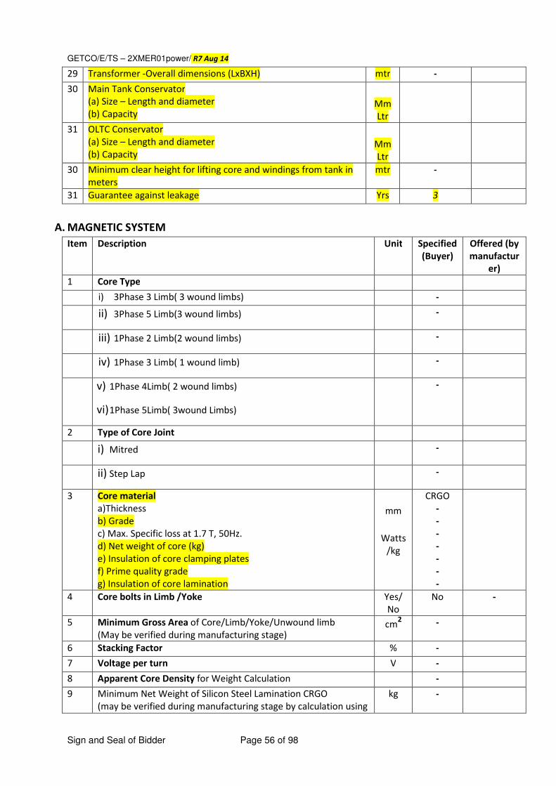
GETCO/E/TS – 2XMER01power/ R7 Aug 14
Sign and Seal of Bidder Page 56 of 98
29 Transformer -Overall dimensions (LxBXH) mtr - 30 Main Tank Conservator
(a) Size – Length and diameter (b) Capacity
Mm Ltr
31 OLTC Conservator (a) Size – Length and diameter (b) Capacity
Mm Ltr
30 Minimum clear height for lifting core and windings from tank in
meters mtr -
31 Guarantee against leakage Yrs 3
A. MAGNETIC SYSTEM
Item Description Unit Specified
(Buyer) Offered (by
manufactur
er) 1 Core Type i) 3Phase 3 Limb( 3 wound limbs) - ii) 3Phase 5 Limb(3 wound limbs) -
iii) 1Phase 2 Limb(2 wound limbs) -
iv) 1Phase 3 Limb( 1 wound limb) -
v) 1Phase 4Limb( 2 wound limbs)
vi) 1Phase 5Limb( 3wound Limbs)
-
2 Type of Core Joint i) Mitred -
ii) Step Lap -
3 Core material a)Thickness b) Grade c) Max. Specific loss at 1.7 T, 50Hz. d) Net weight of core (kg) e) Insulation of core clamping plates f) Prime quality grade g) Insulation of core lamination
mm
Watts
/kg
CRGO - - - - - - -
4 Core bolts in Limb /Yoke Yes/
No No -
5 Minimum Gross Area of Core/Limb/Yoke/Unwound limb (May be verified during manufacturing stage)
cm2 -
6 Stacking Factor % - 7 Voltage per turn V - 8 Apparent Core Density for Weight Calculation - 9 Minimum Net Weight of Silicon Steel Lamination CRGO
(may be verified during manufacturing stage by calculation using
kg -
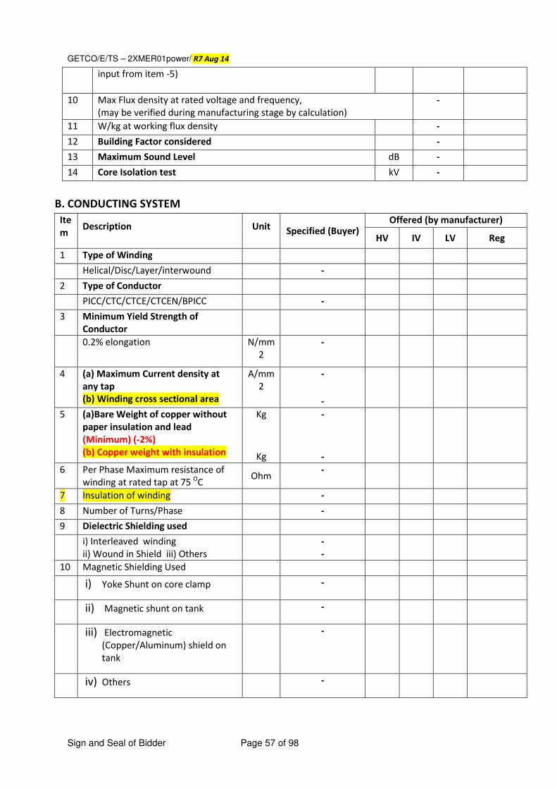
GETCO/E/TS – 2XMER01power/ R7 Aug 14
Sign and Seal of Bidder Page 57 of 98
input from item -5)
10 Max Flux density at rated voltage and frequency, (may be verified during manufacturing stage by calculation)
-
11 W/kg at working flux density - 12 Building Factor considered - 13 Maximum Sound Level dB - 14 Core Isolation test kV -
B. CONDUCTING SYSTEM
Ite
m Description Unit Specified (Buyer)
Offered (by manufacturer)
HV IV LV Reg
1 Type of Winding
Helical/Disc/Layer/interwound -
2 Type of Conductor
PICC/CTC/CTCE/CTCEN/BPICC -
3 Minimum Yield Strength of
Conductor
0.2% elongation N/mm
2 -
4 (a) Maximum Current density at
any tap (b) Winding cross sectional area
A/mm
2 -
-
5 (a)Bare Weight of copper without
paper insulation and lead
(Minimum) (-2%) (b) Copper weight with insulation
Kg
Kg
-
-
6 Per Phase Maximum resistance of
winding at rated tap at 75 OC
Ohm -
7 Insulation of winding - 8 Number of Turns/Phase -
9 Dielectric Shielding used
i) Interleaved winding ii) Wound in Shield iii) Others
- -
10 Magnetic Shielding Used
i) Yoke Shunt on core clamp -
ii) Magnetic shunt on tank -
iii) Electromagnetic
(Copper/Aluminum) shield on
tank
-
iv) Others -
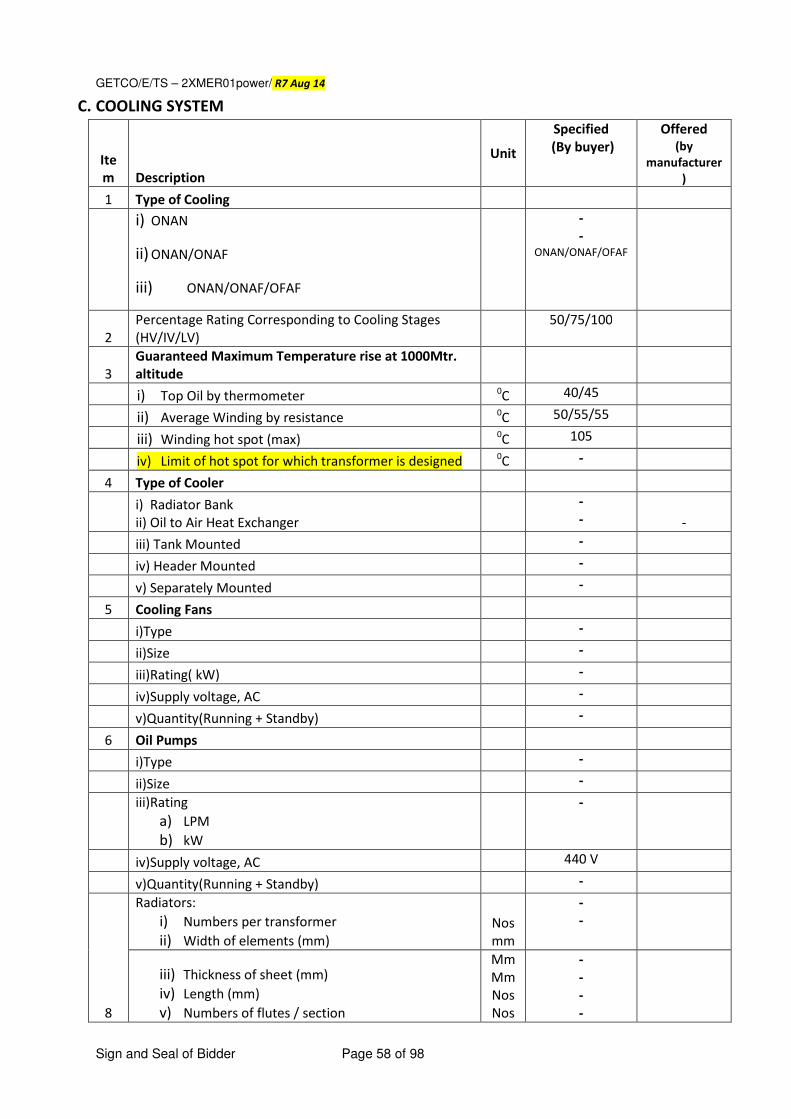
GETCO/E/TS – 2XMER01power/ R7 Aug 14
Sign and Seal of Bidder Page 58 of 98
C. COOLING SYSTEM
Ite
m Description
Unit
Specified (By buyer)
Offered (by
manufacturer
)
1 Type of Cooling
i) ONAN
ii) ONAN/ONAF
iii) ONAN/ONAF/OFAF
- -
ONAN/ONAF/OFAF
2 Percentage Rating Corresponding to Cooling Stages
(HV/IV/LV) 50/75/100
3 Guaranteed Maximum Temperature rise at 1000Mtr.
altitude
i) Top Oil by thermometer 0C 40/45
ii) Average Winding by resistance 0C 50/55/55
iii) Winding hot spot (max) 0C 105
iv) Limit of hot spot for which transformer is designed 0C
-
4 Type of Cooler
i) Radiator Bank ii) Oil to Air Heat Exchanger
- -
-
iii) Tank Mounted -
iv) Header Mounted -
v) Separately Mounted -
5 Cooling Fans
i)Type -
ii)Size -
iii)Rating( kW) -
iv)Supply voltage, AC -
v)Quantity(Running + Standby) -
6 Oil Pumps
i)Type -
ii)Size -
iii)Rating a) LPM
b) kW
-
iv)Supply voltage, AC 440 V
v)Quantity(Running + Standby) -
8
Radiators: i) Numbers per transformer
ii) Width of elements (mm)
Nos mm
- -
iii) Thickness of sheet (mm)
iv) Length (mm)
v) Numbers of flutes / section
Mm Mm Nos Nos
- - - -
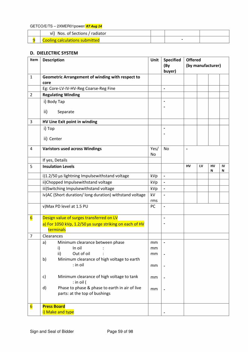
GETCO/E/TS – 2XMER01power/ R7 Aug 14
Sign and Seal of Bidder Page 59 of 98
vi) Nos. of Sections / radiator
9 Cooling calculations submitted -
D. DIELECTRIC SYSTEM
Item Description Unit Specified
(By
buyer)
Offered (by manufacturer)
1 Geometric Arrangement of winding with respect to
core
Eg: Core-LV-IV-HV-Reg Coarse-Reg Fine -
2 Regulating Winding
i) Body Tap
ii) Separate
- -
3 HV Line Exit point in winding
i) Top
ii) Center
- -
4 Varistors used across Windings Yes/
No
No -
If yes, Details
5 Insulation Levels HV LV HV
N
IV
N
i)1.2/50 µs lightning Impulsewithstand voltage kVp -
ii)Chopped Impulsewithstand voltage kVp -
iii)Switching Impulsewithstand voltage kVp -
iv)AC (Short duration/ long duration) withstand voltage kV
rms
-
v)Max PD level at 1.5 PU PC -
6 Design value of surges transferred on LV
a) For 1050 kVp, 1.2/50 µs surge striking on each of HV
terminals
- -
7 Clearances
a) Minimum clearance between phase
i) In oil :
ii) Out of oil :
b) Minimum clearance of high voltage to earth
: in oil
c) Minimum clearance of high voltage to tank
: in oil (
d) Phase to phase & phase to earth in air of live
parts: at the top of bushings
mm
mm
mm
mm
mm
mm
-
-
-
-
-
6 Press Board i) Make and type
-
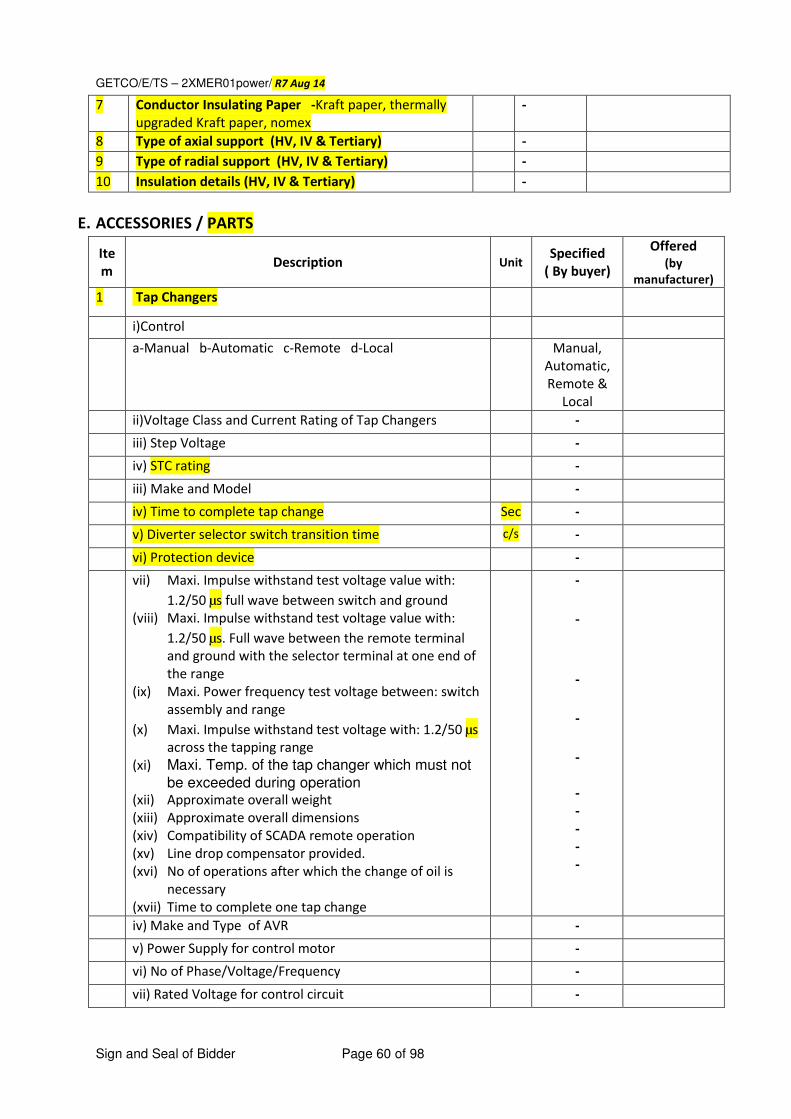
GETCO/E/TS – 2XMER01power/ R7 Aug 14
Sign and Seal of Bidder Page 60 of 98
7 Conductor Insulating Paper -Kraft paper, thermally
upgraded Kraft paper, nomex -
8 Type of axial support (HV, IV & Tertiary) -
9 Type of radial support (HV, IV & Tertiary) -
10 Insulation details (HV, IV & Tertiary) -
E. ACCESSORIES / PARTS
Ite
m Description Unit
Specified ( By buyer)
Offered (by
manufacturer) 1 Tap Changers
i)Control a-Manual b-Automatic c-Remote d-Local Manual,
Automatic,
Remote &
Local
ii)Voltage Class and Current Rating of Tap Changers -
iii) Step Voltage -
iv) STC rating -
iii) Make and Model -
iv) Time to complete tap change Sec -
v) Diverter selector switch transition time c/s -
vi) Protection device -
vii) Maxi. Impulse withstand test voltage value with:
1.2/50 µs full wave between switch and ground (viii) Maxi. Impulse withstand test voltage value with:
1.2/50 µs. Full wave between the remote terminal
and ground with the selector terminal at one end of
the range (ix) Maxi. Power frequency test voltage between: switch
assembly and range
(x) Maxi. Impulse withstand test voltage with: 1.2/50 µs
across the tapping range (xi) Maxi. Temp. of the tap changer which must not
be exceeded during operation (xii) Approximate overall weight (xiii) Approximate overall dimensions (xiv) Compatibility of SCADA remote operation (xv) Line drop compensator provided. (xvi) No of operations after which the change of oil is
necessary (xvii) Time to complete one tap change
-
-
-
-
-
- - - - -
iv) Make and Type of AVR -
v) Power Supply for control motor -
vi) No of Phase/Voltage/Frequency -
vii) Rated Voltage for control circuit -
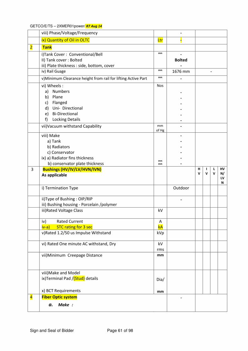
GETCO/E/TS – 2XMER01power/ R7 Aug 14
Sign and Seal of Bidder Page 61 of 98
viii) Phase/Voltage/Frequency -
ix) Quantity of Oil in OLTC Ltr -
2 Tank
i)Tank Cover : Conventional/Bell II) Tank cover : Bolted iii) Plate thickness : side, bottom, cover
mm - Bolted
-
iv) Rail Guage mm 1676 mm -
v)Minimum Clearance height from rail for lifting Active Part mm -
vi) Wheels : a) Numbers b) Plane c) Flanged d) Uni- Directional e) Bi-Directional f) Locking Details
Nos - - - - - -
vii)Vacuum withstand Capability mm
of Hg -
viii) Make a) Tank b) Radiators c) Conservator
ix) a) Radiator fins thickness b) conservator plate thickness
mm mm
- - - - - -
3 Bushings (HV/IV/LV/HVN/IVN)
As applicable H
V
I
V
L
V
HV
N/
LV
N
i) Termination Type Outdoor
ii)Type of Bushing : OIP/RIP iii) Bushing housing - Porcelain /polymer
-
iii)Rated Voltage Class kV
iv) Rated Current iv-a) STC rating for 3 sec
A kA
v)Rated 1.2/50 us Impulse Withstand kVp
vi) Rated One minute AC withstand, Dry kV
rms
vii)Minimum Creepage Distance mm
viii)Make and Model ix)Terminal Pad /(Stud) details
x) BCT Requirements
Dia/
mm
4 Fiber Optic system -
a. Make :
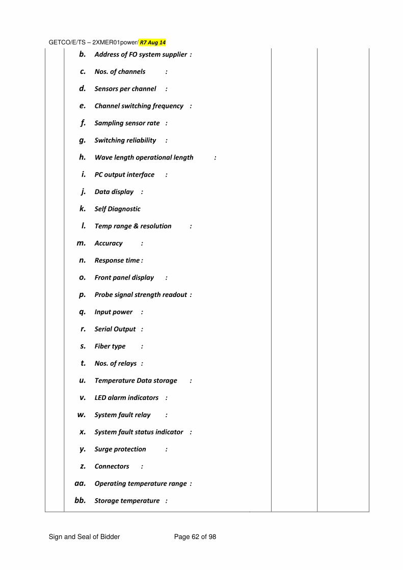
GETCO/E/TS – 2XMER01power/ R7 Aug 14
Sign and Seal of Bidder Page 62 of 98
b. Address of FO system supplier :
c. Nos. of channels :
d. Sensors per channel :
e. Channel switching frequency :
f. Sampling sensor rate :
g. Switching reliability :
h. Wave length operational length :
i. PC output interface :
j. Data display :
k. Self Diagnostic
l. Temp range & resolution :
m. Accuracy :
n. Response time :
o. Front panel display :
p. Probe signal strength readout :
q. Input power :
r. Serial Output :
s. Fiber type :
t. Nos. of relays :
u. Temperature Data storage :
v. LED alarm indicators :
w. System fault relay :
x. System fault status indicator :
y. Surge protection :
z. Connectors :
aa. Operating temperature range :
bb. Storage temperature :
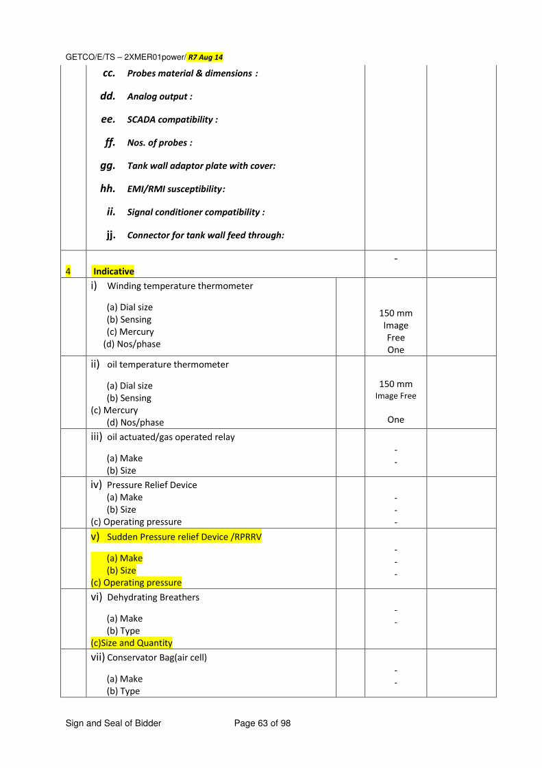
GETCO/E/TS – 2XMER01power/ R7 Aug 14
Sign and Seal of Bidder Page 63 of 98
cc. Probes material & dimensions :
dd. Analog output :
ee. SCADA compatibility :
ff. Nos. of probes :
gg. Tank wall adaptor plate with cover:
hh. EMI/RMI susceptibility :
ii. Signal conditioner compatibility :
jj. Connector for tank wall feed through:
4
Indicative
-
i) Winding temperature thermometer
(a) Dial size (b) Sensing (c) Mercury
(d) Nos/phase
150 mm Image Free One
ii) oil temperature thermometer
(a) Dial size (b) Sensing (c) Mercury (d) Nos/phase
150 mm
Image Free
One
iii) oil actuated/gas operated relay
(a) Make (b) Size
- -
iv) Pressure Relief Device (a) Make (b) Size (c) Operating pressure
- - -
v) Sudden Pressure relief Device /RPRRV
(a) Make (b) Size (c) Operating pressure
- - -
vi) Dehydrating Breathers
(a) Make (b) Type (c)Size and Quantity
- -
vii) Conservator Bag(air cell)
(a) Make (b) Type
- -
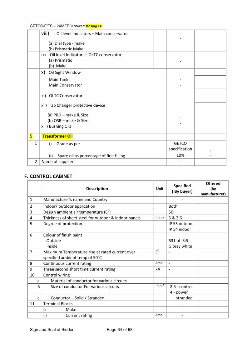
GETCO/E/TS – 2XMER01power/ R7 Aug 14
Sign and Seal of Bidder Page 64 of 98
viii) Oil level Indicators – Main conservator
(a) Dial type - make (b) Prismatic Make
- -
ix) Oil level Indicators – OLTC conservator
(a) Prismatic
(b) Make
-
x) Oil Sight Window Main Tank
Main Conservator
- -
xi) OLTC Conservator -
xii) Tap Changer protective device
(a) PRD – make & Size (b) OSR – make & Size xiii) Bushing CTs
- -
5 Transformer Oil
1 i) Grade as per
ii) Spare oil as percentage of first filling
GETCO
specification
10%
- -
2 Name of supplier -
F. CONTROL CABINET
Description Unit Specified
( By buyer)
Offered (by
manufacturer) 1 Manufacturer's name and Country - 2 Indoor/ outdoor application Both
3 Design ambient air temperature (C0) 50
4 Thickness of sheet steel for outdoor & indoor panels (mm) 3 & 2.6
5 Degree of protection IP 55 outdoor
IP 54 indoor
6 Colour of finish paint
Outside
Inside
631 of IS:5
Glossy white
7 Maximum Temperature rise at rated current over
specified ambient temp of 500C
C0 -
8 Continuous current rating Amp -
9 Three second short time current rating kA -
10 Control wiring
a Material of conductor for various circuits -
B Size of conductor For various circuits mm2 2.5 - control
4 - power
c Conductor – Solid / Stranded stranded
11 Terminal Blocks -
i) Make -
ii) Current rating Amp -
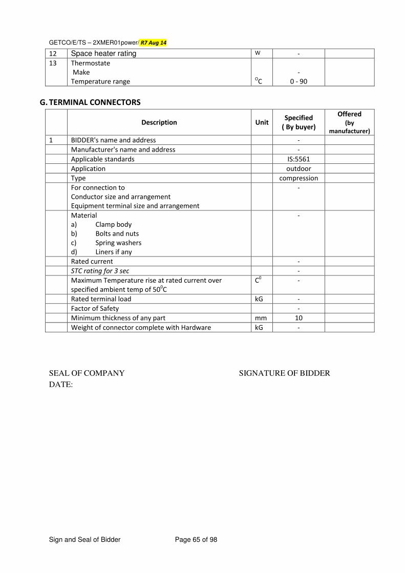
GETCO/E/TS – 2XMER01power/ R7 Aug 14
Sign and Seal of Bidder Page 65 of 98
12 Space heater rating W -
13 Thermostate
Make
Temperature range
OC
-
0 - 90
G. TERMINAL CONNECTORS
Description Unit Specified
( By buyer)
Offered
(by
manufacturer)
1 BIDDER's name and address -
Manufacturer's name and address -
Applicable standards IS:5561
Application outdoor
Type compression
For connection to
Conductor size and arrangement
Equipment terminal size and arrangement
-
Material
a) Clamp body
b) Bolts and nuts
c) Spring washers
d) Liners if any
-
Rated current -
STC rating for 3 sec -
Maximum Temperature rise at rated current over
specified ambient temp of 500C
C0 -
Rated terminal load kG -
Factor of Safety -
Minimum thickness of any part mm 10
Weight of connector complete with Hardware kG -
SEAL OF COMPANY SIGNATURE OF BIDDER
DATE:
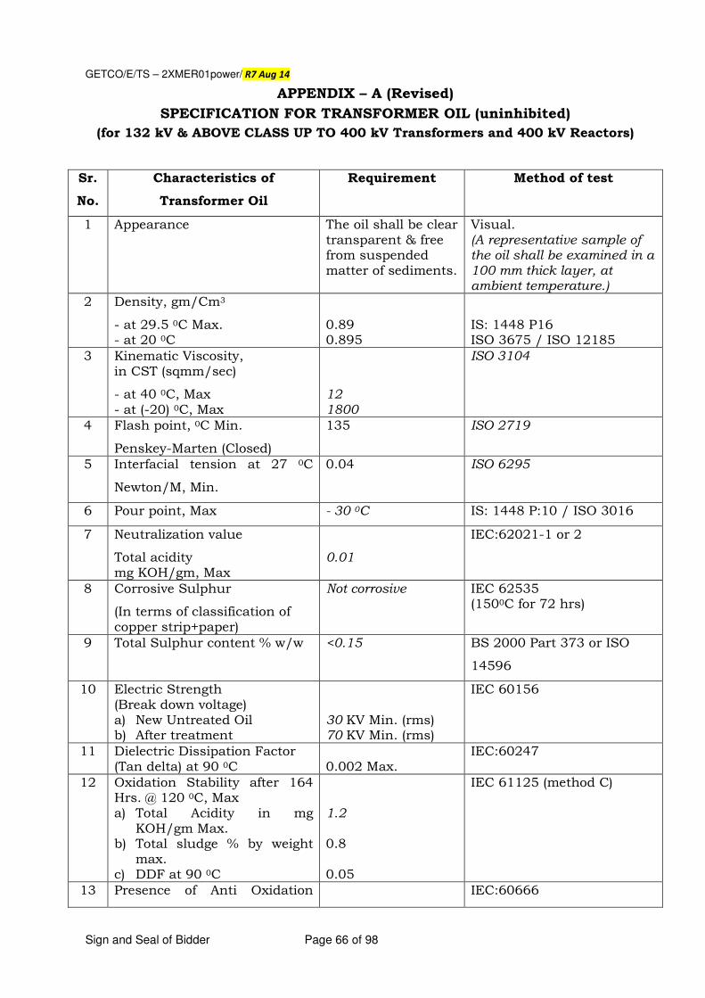
GETCO/E/TS – 2XMER01power/ R7 Aug 14
Sign and Seal of Bidder Page 66 of 98
APPENDIX – A (Revised)
SPECIFICATION FOR TRANSFORMER OIL (uninhibited)
(for 132 kV & ABOVE CLASS UP TO 400 kV Transformers and 400 kV Reactors)
Sr.
No.
Characteristics of
Transformer Oil
Requirement Method of test
1 Appearance The oil shall be clear transparent & free from suspended matter of sediments.
Visual. (A representative sample of the oil shall be examined in a 100 mm thick layer, at ambient temperature.)
2 Density, gm/Cm3
- at 29.5 0C Max. - at 20 0C
0.89 0.895
IS: 1448 P16 ISO 3675 / ISO 12185
3 Kinematic Viscosity, in CST (sqmm/sec)
- at 40 0C, Max - at (-20) 0C, Max
12 1800
ISO 3104
4 Flash point, 0C Min.
Penskey-Marten (Closed)
135 ISO 2719
5 Interfacial tension at 27 0C
Newton/M, Min.
0.04 ISO 6295
6 Pour point, Max - 30 0C IS: 1448 P:10 / ISO 3016
7 Neutralization value
Total acidity mg KOH/gm, Max
0.01
IEC:62021-1 or 2
8 Corrosive Sulphur
(In terms of classification of copper strip+paper)
Not corrosive IEC 62535 (1500C for 72 hrs)
9 Total Sulphur content % w/w <0.15 BS 2000 Part 373 or ISO
14596
10 Electric Strength (Break down voltage) a) New Untreated Oil b) After treatment
30 KV Min. (rms) 70 KV Min. (rms)
IEC 60156
11 Dielectric Dissipation Factor (Tan delta) at 90 0C
0.002 Max.
IEC:60247
12 Oxidation Stability after 164 Hrs. @ 120 0C, Max a) Total Acidity in mg
KOH/gm Max. b) Total sludge % by weight
max. c) DDF at 90 0C
1.2 0.8 0.05
IEC 61125 (method C)
13 Presence of Anti Oxidation IEC:60666
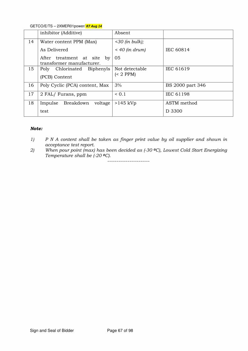
GETCO/E/TS – 2XMER01power/ R7 Aug 14
Sign and Seal of Bidder Page 67 of 98
inhibitor (Additive) Absent
14 Water content PPM (Max)
As Delivered
After treatment at site by transformer manufacturer.
<30 (in bulk);
< 40 (in drum)
05
IEC 60814
15 Poly Chlorinated Biphenyls
(PCB) Content
Not detectable (< 2 PPM)
IEC 61619
16 Poly Cyclic (PCA) content, Max 3% BS 2000 part 346
17 2 FAL/ Furans, ppm < 0.1 IEC 61198
18 Impulse Breakdown voltage
test
>145 kVp ASTM method
D 3300
Note: 1) P N A content shall be taken as finger print value by oil supplier and shown in
acceptance test report. 2) When pour point (max) has been decided as (-30 0C), Lowest Cold Start Energizing
Temperature shall be (-20 0C). -----------------------
GETCO/E/TS – 2XMER01power/ R7 Aug 14
Sign and Seal of Bidder Page 68 of 98
APPENDIX – B
1.0 QUALIFICATION REQUIREMENTS FOR ERECTION, TESTING & COMMISSIONING
1.1 The bidder should have carried out erection, testing, commissioning of and
test charging of at least two nos. of 220 kV or above class transformers at 220 kV &/or 400 kV switch yard of sub stations satisfactory during last five years before date of submission of the bid.
1.2 The bidder should arrange requisite tools and tackles including adequate
capacity hydraulic crane having suitable adjustable boom length for erection of bushing, radiators, conservator, and other associated costly equipments.
1.3 The bidder should have team of trained personnel and skilled labour force
and supervising engineers to carry out erection, commissioning, testing and test charging work including laying of control cables and wiring of OLTC gear scheme and inter connection of RTCC panel with D.M., of OLTC., wiring of cooler control scheme and cooling fans including automatic operation of cooler control etc.
2.0 ERECTION OF POWER TRANSFORMER
2.1 Erection includes entire vacuum by proper capacity of vacuum pump, for not less than 48 hours, or more if required as per the instruction of engineer in charge.
2.2 Oil may be supplied in tanker/steel drums, which should be properly sealed during
transportation and storage. Seal shall be verified and opened by GETCO representative
before filling in transformer. Contractor should have enough storage capacity for
handling oil. Filling the oil from tank/drums to the transformer through 6000 liters capacity of high quality filter machine and filtration of the same to get desired BDV &PPM as specified by engineer in charge and transformer manual.
2.3 Contractor has to replace all the gaskets by new ones if required by engineer –in –charge.
2.4 Erection shall include wiring of cooling fans, RTCC panels, terminations of alarm and trip contacts from buchholz relay, WTI, OTI, PRD to M.K. box and in turn to remote relay panel and RTCC panel in control room. Required cabling on the transformer as well as from transformer to control room shall also be included in scope of work. The testing and commissioning of OLTC as well as cooler control scheme shall be carried out as per instruction of engineer in charge.
2.5 The contractor shall arrange nitrogen cylinder required at site for above work.
2.6 In case of any breakage of any item, contractor has to follow up with insurance for the claims and amount for damage /breakage will be with
GETCO/E/TS – 2XMER01power/ R7 Aug 14
Sign and Seal of Bidder Page 69 of 98
held from contractor’s bill till the time claim is finalized by insurance company.
2.7 Minimum 15 Nos. of good skilled fitters, with 2 Nos. qualified supervisors and senior engineer having sufficient experience should be posted at site during the above work.
2.8 Contractor has to repaint the transformer tank with two coat of anti rusting good finish LTBS grey shade 632 of IS:5 by spray painting as per the direction of engineer in charge.
2.9 Contractor is required to carry out all minor/major fabrication work of pipes and hangers if required at site as per direction of engineer in charge.
2.10 All tools and tackles, testing equipments listed here under are to be arranged by the contractor.
2.11 Contractor shall arrange required capacity of oil tanker at site. 2.12 Any other items not mentioned above but required for successful
completion of erection shall have to be arranged by the contractor. 3.0 TOOLS REQUIRD FOR ERECTION
1. One or two mobile crane hydraulic of adequate capacity with long boom of
30 ft. bearing free vertical lifts suitable for lifting HV bushing.
2. Steel/Manila/Nylon ropes and D shackle for lifting of 3-ton weight.
3. 4000 or 6000 liters. / hr. capacity filter machine in excellent working
condition. It must be capable of heating transformer oil up to 800 C and
must be equipped with built in high vacuum pump and chamber filter
elements.
4. Following accessories should also be made available.
a) Non-collapsible hose piping of size 40 mm to 80 mm with nipple and flange.
b) Hosepipe should be of oil resistant 2�� to 3�� BSP suitably threaded for
connecting hose pipes & provided with holes for fastening.
c) 2 Nos. storage tanks for insulating oil of adequate capacity provided with 2
bottom drain cum filter valve and another 2�� top valve.
d) Two complete sets of ring and flat spanners of metric size up to 4 to 36.
e) One complete set of Allen keys.
f) One complete set of screw derivers.
g) ¼” shackle 3-ply nylon rope of 15 mtr. Length.
h) 4 nos. of flange each of 1”, 2” to 3” BSP suitably threaded for connecting
hose pipe & provided with holes for fastening.
i) Multi stage vacuum pumping system capacity 250-500 mm cu/hr. & should
be able to create absolute vacuum of 1 tor or 1.3 m bar or less having
following accessories.
j) Non return valve at inlet.
k) GI pipe/non-collapsible pipes with flange for connecting vacuum pump to
transformer main tank.
GETCO/E/TS – 2XMER01power/ R7 Aug 14
Sign and Seal of Bidder Page 70 of 98
l) Vacuum gauge for reading 0 to 50 mm along with flange for fitting at top of
transformer of any suitable size 3/16” and 3/8” set in good quality.
m) Oil testing kit in good working condition having 2.5mm and 4 mm gauge for
adjusting the gap, 2.5/5 KV megger motor driven and capable of reading up
to 50000 M-OHM.
n) Hot air blower for drying out of bushing.
o) Required nitrogen cylinder.
p) Stainless steel bottles for samples.
q) Gas cylinder with nozzle torch for gas cutting etc.
r) Any other item required for successful completion of work.
s) Tools required for erection are on returnable basis.
SEAL OF COMPANY SIGNATURE OF BIDDER
DATE:
GETCO/E/TS – 2XMER01power/ R7 Aug 14
Sign and Seal of Bidder Page 71 of 98
ANNEXURE - I AUTOMATIC VOLTAGE REGULATING RELAY
1. Automatic voltage control shall be initiated by a voltage regulating relay of an approved
make and suitable for flush and/or wall mounting / DIN-rail / rack mounting.
2. The relay shall operate from the nominal reference voltage derived form a circuit mounted 1 phase / 3 phase Voltage transformer (VT).
3. The AVR relay shall be Microprocessor based Numerical relay having large LCD display 128x128 or higher.
4. The relay shall have 4 selectable set point voltages. 5. The AVR relay shall have the following methods as option for the compensation of
voltage.
� Apparent Current (Z-Comp.) � Line drop compensation (LDC) � Active Current � Reactive current
6. The relay bandwidth shall be adjustable between –5 to +15 of set point voltage to suit per
step voltage of 1.25%.
7. The relay shall have following options regarding time behavior with Time factor selectable from 0.1 to 30.
� Linear � Integral � Fast integral
8. The relay shall incorporate an under voltage / over voltage blocking facility which shall
make the control inoperative if voltage falls / rises by percentage value of set point value (as mentioned in Guaranteed technical particulars) with automatic restoration of control when nominal voltage rises / falls to value as mentioned in the Guaranteed technical particulars.
9. The AVR relay shall have integrated features for the display of following parameters
� Integrated tap changer position display � Nominal Voltage � Load current � Bandwidth � Measuring values V. I. Active power, Reactive power, Apparent power, phase
angle, Power factor, Reactive current and frequency 10. The AVR relay shall have facility to compensate the VT and CT-errors. 11. The AVR relay shall have facility to register the tap changer statistics. In the statistics
mode, the relay shall display the no. of tap changing operations occurred on each tap. 12. The AVR relay shall have facility to recode the voltage and current with respect to time.
Each of voltage value shall be measured for 100ms and averaged for 1 second. The recorded values shall be presented in graphical format on the device.
13. The AVR relay shall have integrated feature to make the parallel operation of 10 transformers working in parallel. The relay shall be self sufficient and shall not require any additional devices like parallel balancing module etc. At least following principal shall be available in the relay as standard.
� Master Follower / Master Slave � Circulating current
14. The AVR relay shall have facility to monitor or control the following parameters
GETCO/E/TS – 2XMER01power/ R7 Aug 14
Sign and Seal of Bidder Page 72 of 98
� Monitoring of life time consumption of transformer � Monitoring of operating hours of Tap changer, Fans and Pump � Control of cooling levels of transformer � Recording of Hot spot temperature
15. The AVR relay shall have facility to record specific events (Event-Recorder) like under
voltage, over voltage, Over current, Auto/Manual, local/remote etc. with date and time stamping.
16. The AVR relay shall have facility to make selection of Auto/Manual and Local/Remote. 17. The AVR relay shall have different LEDs to indicate Service and Blocked condition. 18. It is preferred that 12 nos of freely programmable LEDs duly tagged or stickered shall be
available to indicate different Operations / Alarm / Faults condition. If stickers are provided,
then 5 sets of such stickers shall be supplied free of cost for future replacement.
19. The AVR relay shall have freely programmable Binary Inputs, Binary outputs, Analog Inputs and Analog Outputs.
20. The AVR relay shall have software to make the parameter settings of the device and it shall also be possible to do the parameter setting through keyboard of relay.
21. The AVR relay shall have suitable interface to make communication with higher level SCADA system. The following minimum ports shall be available on the device.
a. RS 232 port (COM 1) for doing the parameter setting and local communication with
device. b. RS 485, Fiber optic ports for communication with higher level SCADA with protocols
like MODBUS & IEC 61850. 22. It shall be possible to communicate via bus with all similar devices located at different
location by making communication link with any one device through its RS 485 - port or Fiber Optic port meant for SCADA communication.
23. It shall have facility by which a customer specific software programme can be written and incorporated as feature in the relay.
SEAL OF COMPANY SIGNATURE OF BIDDER
DATE:
GETCO/E/TS – 2XMER01power/ R7 Aug 14
Sign and Seal of Bidder Page 73 of 98
ANNEXURE C
List of documents attached with technical bid:
Bidder shall invariably attach the following documents and clearly marked and duly
flagged in technical bid. In absence of these documents offer will be evaluated as a non
submission.
Sr. No. Particulars of document Whether attached
with tech bid
1 Drawings in AutoCAD format
2 Drawings hard copies as indicated in specification
3 Manual in PDF format
4 QAP for manufacturing process in SOFT format
5 QAP for manufacturing process in Hard format
6 FQP in SOFT format
7 FQP in Hard copy
8 Type test Reports in hard copies
a for transformer
b for OLTC
c for control cabinet
d for clamps & connectors
e for Air cell
9 Confirmation regarding type tests as per clause no. Cl.
1.30.3.1(b) page no. 32 – “IMPORTANT NOTE”
10 Calculation of Thermal stability to withstand short
circuits
11 Calculation of Dynamic ability to withstand short circuits
12 Cooling calculation
13 Guaranteed Technical Particulars, completely filled in
a for transformer
b for OLTC
c for control cabinet
d for clamps & connectors
e for Air cell
14 Any other essential documents
SIGNATURE OF BIDDER COMPANY’S ROUND SEAL DATE: PLACE:
GETCO/E/TS – 2XMER01power/ R7 Aug 14
Sign and Seal of Bidder Page 74 of 98
ANNEXURE – IV
SECTION: I
DETAIL SPECIFICATION OF FLEXIBLE SEPARATOR (AIR CELL) GENERAL TECHNICAL REQUIREMENTS
1.1 SCOPE: 1.1.1 This section covers the design, manufacture, assembly, testing at
manufacturer’s works, supply and delivery of the Flexible Separator (Air cell) as detailed in the Schedule – A of the commercial bid, complete with all accessories required for satisfactory and trouble free operation of the equipment.
1.1.2 When it is an item purchase or supply with transformer, the scope of work
shall be design, manufacture, assembly, testing at manufacturer’s works, supply and delivery of Flexible Separator (Air cell) & it’s all required accessories.
OR when it is job work of providing and fixing, then the scope of work shall be
design, manufacture, assembly, testing at manufacturer’s works, supply, delivery, including all required fabrication, fittings, valves, gauges, pipes etc., and complete erection, testing and successful commissioning for a given transformer conservator indicated in Schedule – A of the commercial bid.
1.1.3 GUARANTEE:
The bidder shall among other things guarantee the following: i) Quality and strength of materials used. ii) The bidder shall give the guarantee as satisfactory working of the complete
transformer for 36 months from the date of commissioning of Flexible Separator (Air cell) or 42 months from the date of receipt of at site, whichever is earlier.
It may be noted that the service guarantee would be applicable even when the Flexible Separator (Air cell) is erected and operated through any other agency appointed by the GETCO.
2.0 CONSTRUCTION:
GETCO/E/TS – 2XMER01power/ R7 Aug 14
Sign and Seal of Bidder Page 75 of 98
The construction of Flexible Separator (Air cell) shall be of Polymide/nylon fabric coated on both side with synthetic rubber and meeting the complete requirement of this specification.
Adhesives used shall be compatible with air and transformer oil at 100oC. All
the joints shall be properly designed & suitably vulcanized. Further, Flexible Separator (Air cell) shall be reinforced at bottom face to avoid damage due to contact with magnetic oil gauge float. There shall not be any patch work in Flexible Separator (Air cell). Adaptor used shall be made from structural steel confirming to Fe-410-S to IS:226. Adaptor and bolts shall be cadmium plated and passivated (CD-8 of IS:1572) or Zinc plated and passivated.(Fe Zn 12.5 of IS:1573). The width of the overlap at the joints shall be such that there is no possibility of joint opening and leakage. Minimum width shall be 75 mm.
3.0 FUNCTIONAL REQUIREMENTS:
i) The function of Flexible Separator (Air cell) is to line the inside of the conservator tank in transformer, allowing for changes in volume, while protecting the oil from any type of contamination or external corrosive agents like ozone, nitrogen, humidity etc.
ii) Flexible Separator (Air cell) shall be suitable for continuous use in transformer oil at -20oC to 100o C.
iii) Inside coating shall be very good enough to resist weather and ozone. Outside coating shall be transformer oil resistant. Compounds used for coating shall not deteriorate during service.
iv) Flexible Separator (Air cell) shall be suitable for inflation and deflation due to change in oil volume in the conservator. Further, Flexible Separator (Air cell) shall be designed to collapse slowly as oil level rises in the conservator.
v) Flexible Separator (Air cell) shall not develop cracks even at -20oC. vi) Fixation lugs and adaptor shall be provided on the Flexible Separator (Air
cell). vii) Flexible Separator (Air cell) shall have excellent impermeability to oil, gases
and water vapor. viii) Flexible Separator (Air cell) shall have high mechanical resistance. ix) Flanges provided shall meet any of our requirements indicated.
4.0 GENERAL:
The Flexible Separator (Air cell) shall be suitable for conservator of diameter, length & shape indicated in schedule – B, attached separately, with the tender. The suitability & size of Flexible Separator (Air cell) to be provided shall be supported by necessary calculation for given size and shape of conservator. The Flexible Separator (Air cell) conform to relevant IS or international standards shall be indicated in the bid. The type tests and routine/acceptance tests shall be carried out accordingly and report shall be submitted with the bid.
GETCO/E/TS – 2XMER01power/ R7 Aug 14
Sign and Seal of Bidder Page 76 of 98
The work of providing and fixing shall be carried out as per availability of shut down of particular transformer at site. Necessary tools tackles, accessories, manpower, etc required shall be managed by contractor. The guaranteed technical particulars as listed in Section II, but not limited to shall be invariably submitted with the technical bid.
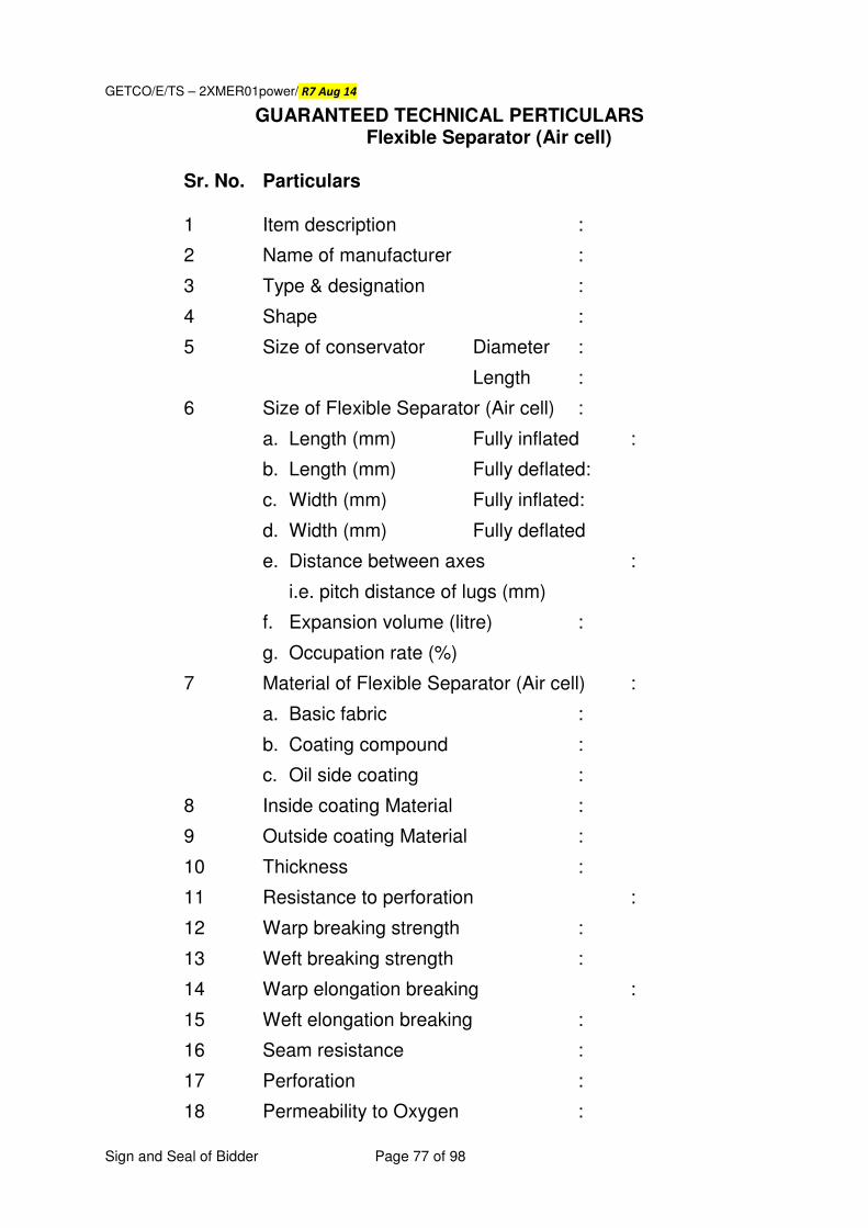
GETCO/E/TS – 2XMER01power/ R7 Aug 14
Sign and Seal of Bidder Page 77 of 98
GUARANTEED TECHNICAL PERTICULARS Flexible Separator (Air cell)
Sr. No. Particulars 1 Item description :
2 Name of manufacturer :
3 Type & designation :
4 Shape :
5 Size of conservator Diameter :
Length :
6 Size of Flexible Separator (Air cell) :
a. Length (mm) Fully inflated :
b. Length (mm) Fully deflated:
c. Width (mm) Fully inflated:
d. Width (mm) Fully deflated
e. Distance between axes :
i.e. pitch distance of lugs (mm)
f. Expansion volume (litre) :
g. Occupation rate (%)
7 Material of Flexible Separator (Air cell) :
a. Basic fabric :
b. Coating compound :
c. Oil side coating :
8 Inside coating Material :
9 Outside coating Material :
10 Thickness :
11 Resistance to perforation :
12 Warp breaking strength :
13 Weft breaking strength :
14 Warp elongation breaking :
15 Weft elongation breaking :
16 Seam resistance :
17 Perforation :
18 Permeability to Oxygen :
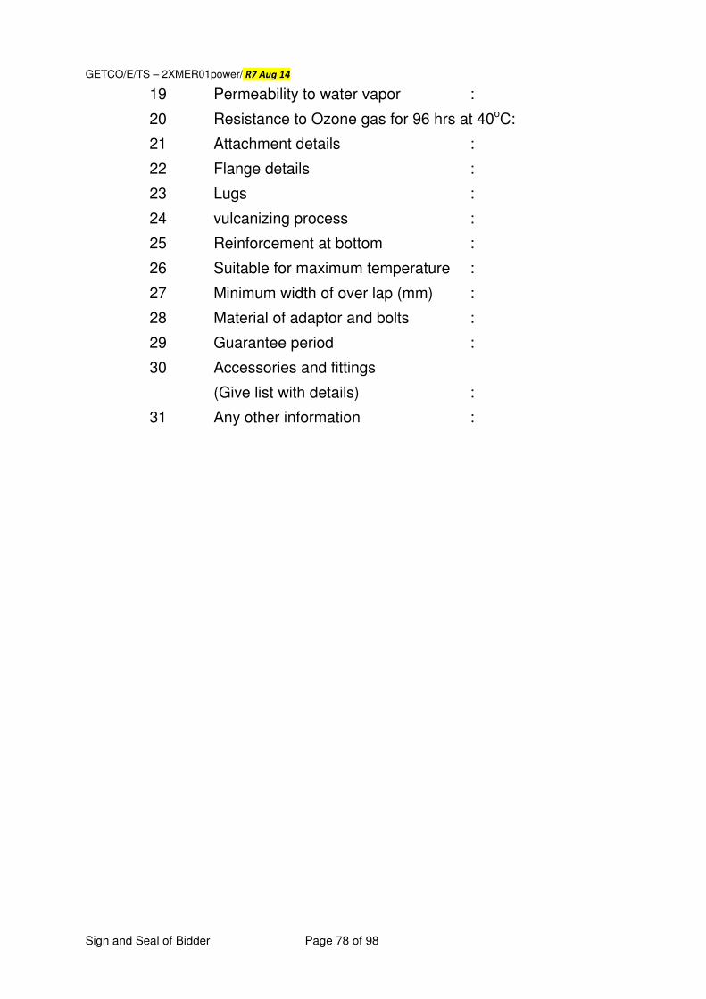
GETCO/E/TS – 2XMER01power/ R7 Aug 14
Sign and Seal of Bidder Page 78 of 98
19 Permeability to water vapor :
20 Resistance to Ozone gas for 96 hrs at 40oC:
21 Attachment details :
22 Flange details :
23 Lugs :
24 vulcanizing process :
25 Reinforcement at bottom :
26 Suitable for maximum temperature :
27 Minimum width of over lap (mm) :
28 Material of adaptor and bolts :
29 Guarantee period :
30 Accessories and fittings
(Give list with details) :
31 Any other information :
GETCO/E/TS – 2XMER01power/ R7 Aug 14
Sign and Seal of Bidder Page 79 of 98
Annexure - II
ON Line Dissolved Gas Analysis Technical Specification For On Line Gas In Oil Analyser
1.0 GENERAL: The transformer shall be equipped with on line gas in oil analyzer system and remote data transfer /communications. It is intended to individual monitor the evolution of dissolved gases from the oil of transformer to detect and continuously monitor a individual value of gases like H2(Hydrogen), CH4 (Methane),C2H4 (ethylene),C2H6 (Ethane), C2H2 (Acetylene), CO2 (Carbon dioxide), CO (Carbon monoxide).,O2 Oxygen,N2 (Nitrogen).The system shall be installed on a single, open bore ball or gate valve. 2.0 SCOPE of WORK: The scope of work shall be to supply, mounting, erection, commissioning, etc; for on line moisture and gas in oil analyzer system of any transformer in GETCO. 2.1 Microprocessor based Intelligent Electronic Device (IED), as required, to
be on a single open bore ball or gate valve mounted on transformer along with all required fittings and accessories.
2.2 One set of centralized monitoring system with suitable software for
communicating with IEDs simultaneously with a provision for communicating to two or more IEDs if required in future. The required software shall be loaded in GETCO system at desired location such that all the data/display associated with the system can be visualized and all archiving / trending can be achieved. It shall also give printouts of all required data as desired.
2.3 All required interconnection, wiring, cabling with fiber optic cables/RS
485 cables etc., including all required accessories for successful operation of the system.
2.4 Required earthing & connection for the system at required location is to
be carried out by bidder. 2.5 Necessary tools, tackles, calibration equipments, installation Material,
required for successful operation of the system is to be carried out by bidder. Tools required for erection are on returnable basis.
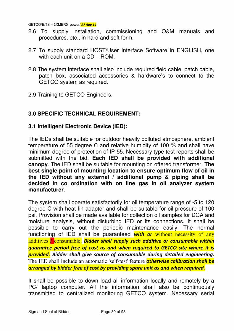
GETCO/E/TS – 2XMER01power/ R7 Aug 14
Sign and Seal of Bidder Page 80 of 98
2.6 To supply installation, commissioning and O&M manuals and procedures, etc., in hard and soft form.
2.7 To supply standard HOST/User Interface Software in ENGLISH, one
with each unit on a CD – ROM. 2.8 The system interface shall also include required field cable, patch cable,
patch box, associated accessories & hardware’s to connect to the GETCO system as required.
2.9 Training to GETCO Engineers. 3.0 SPECIFIC TECHNICAL REQUIREMENT: 3.1 Intelligent Electronic Device (IED): The IEDs shall be suitable for outdoor heavily polluted atmosphere, ambient temperature of 55 degree C and relative humidity of 100 % and shall have minimum degree of protection of IP-55. Necessary type test reports shall be submitted with the bid. Each IED shall be provided with additional canopy. The IED shall be suitable for mounting on offered transformer. The best single point of mounting location to ensure optimum flow of oil in the IED without any external / additional pump & piping shall be decided in co ordination with on line gas in oil analyzer system manufacturer. The system shall operate satisfactorily for oil temperature range of -5 to 120 degree C with heat fin adapter and shall be suitable for oil pressure of 100 psi. Provision shall be made available for collection oil samples for DGA and moisture analysis, without disturbing IED or its connections. It shall be possible to carry out the periodic maintenance easily. The normal functioning of IED shall be guaranteed with or without necessity of any
additives / consumable. Bidder shall supply such additive or consumable within
guarantee period free of cost as and when required to GETCO site where it is
provided. Bidder shall give source of consumable during detailed engineering.
The IED shall include an automatic 'self-test' feature otherwise calibration shall be
arranged by bidder free of cost by providing spare unit as and when required. It shall be possible to down load all information locally and remotely by a PC/ laptop computer. All the information shall also be continuously transmitted to centralized monitoring GETCO system. Necessary serial
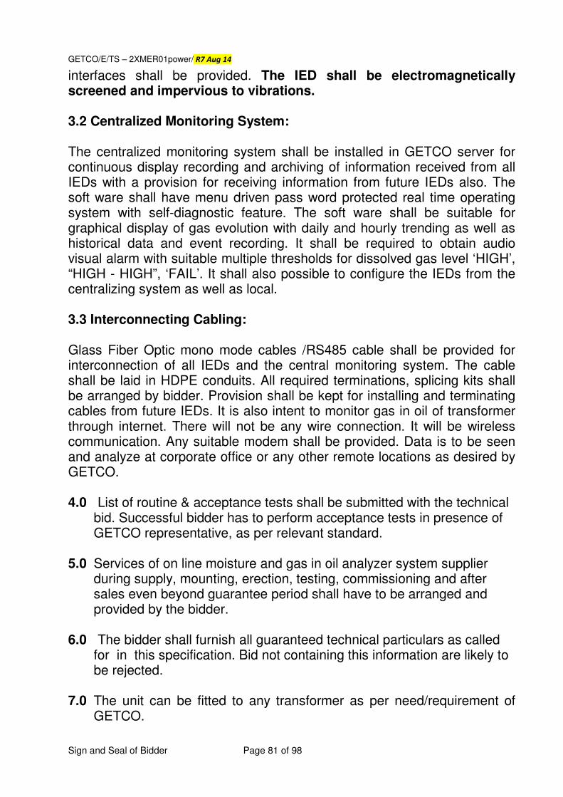
GETCO/E/TS – 2XMER01power/ R7 Aug 14
Sign and Seal of Bidder Page 81 of 98
interfaces shall be provided. The IED shall be electromagnetically screened and impervious to vibrations. 3.2 Centralized Monitoring System: The centralized monitoring system shall be installed in GETCO server for continuous display recording and archiving of information received from all IEDs with a provision for receiving information from future IEDs also. The soft ware shall have menu driven pass word protected real time operating system with self-diagnostic feature. The soft ware shall be suitable for graphical display of gas evolution with daily and hourly trending as well as historical data and event recording. It shall be required to obtain audio visual alarm with suitable multiple thresholds for dissolved gas level ‘HIGH’, “HIGH - HIGH”, ‘FAIL’. It shall also possible to configure the IEDs from the centralizing system as well as local. 3.3 Interconnecting Cabling: Glass Fiber Optic mono mode cables /RS485 cable shall be provided for interconnection of all IEDs and the central monitoring system. The cable shall be laid in HDPE conduits. All required terminations, splicing kits shall be arranged by bidder. Provision shall be kept for installing and terminating cables from future IEDs. It is also intent to monitor gas in oil of transformer through internet. There will not be any wire connection. It will be wireless communication. Any suitable modem shall be provided. Data is to be seen and analyze at corporate office or any other remote locations as desired by GETCO. 4.0 List of routine & acceptance tests shall be submitted with the technical
bid. Successful bidder has to perform acceptance tests in presence of GETCO representative, as per relevant standard.
5.0 Services of on line moisture and gas in oil analyzer system supplier
during supply, mounting, erection, testing, commissioning and after sales even beyond guarantee period shall have to be arranged and provided by the bidder.
6.0 The bidder shall furnish all guaranteed technical particulars as called
for in this specification. Bid not containing this information are likely to be rejected.
7.0 The unit can be fitted to any transformer as per need/requirement of GETCO.
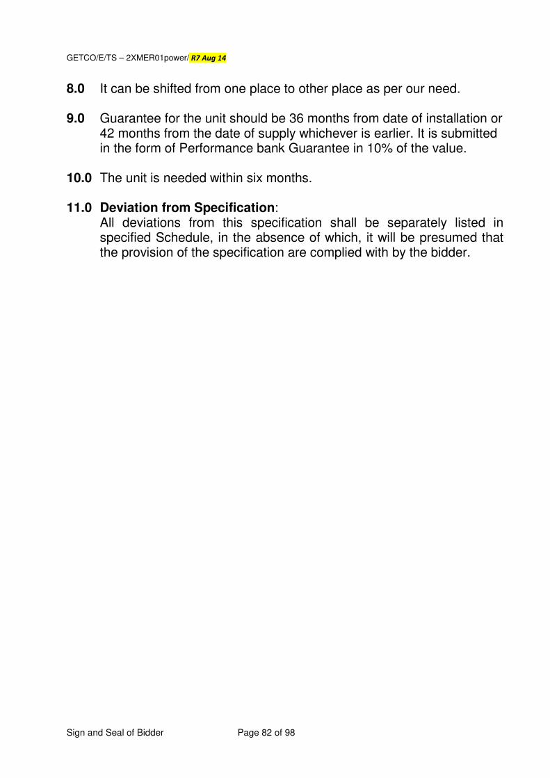
GETCO/E/TS – 2XMER01power/ R7 Aug 14
Sign and Seal of Bidder Page 82 of 98
8.0 It can be shifted from one place to other place as per our need. 9.0 Guarantee for the unit should be 36 months from date of installation or
42 months from the date of supply whichever is earlier. It is submitted in the form of Performance bank Guarantee in 10% of the value.
10.0 The unit is needed within six months. 11.0 Deviation from Specification:
All deviations from this specification shall be separately listed in specified Schedule, in the absence of which, it will be presumed that the provision of the specification are complied with by the bidder.
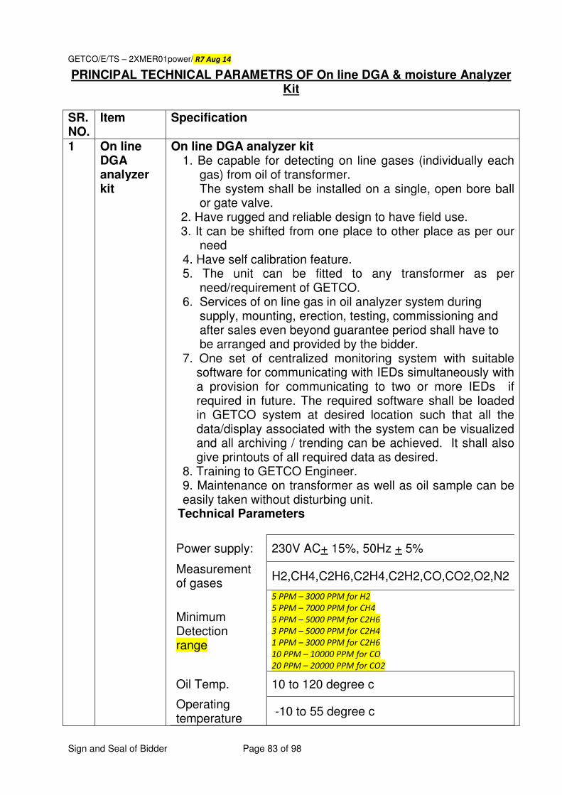
GETCO/E/TS – 2XMER01power/ R7 Aug 14
Sign and Seal of Bidder Page 83 of 98
PRINCIPAL TECHNICAL PARAMETRS OF On line DGA & moisture Analyzer Kit
SR. NO.
Item Specification
1 On line DGA analyzer kit
On line DGA analyzer kit 1. Be capable for detecting on line gases (individually each
gas) from oil of transformer. The system shall be installed on a single, open bore ball or gate valve.
2. Have rugged and reliable design to have field use. 3. It can be shifted from one place to other place as per our
need 4. Have self calibration feature. 5. The unit can be fitted to any transformer as per
need/requirement of GETCO. 6. Services of on line gas in oil analyzer system during
supply, mounting, erection, testing, commissioning and after sales even beyond guarantee period shall have to be arranged and provided by the bidder.
7. One set of centralized monitoring system with suitable software for communicating with IEDs simultaneously with a provision for communicating to two or more IEDs if required in future. The required software shall be loaded in GETCO system at desired location such that all the data/display associated with the system can be visualized and all archiving / trending can be achieved. It shall also give printouts of all required data as desired.
8. Training to GETCO Engineer. 9. Maintenance on transformer as well as oil sample can be easily taken without disturbing unit.
Technical Parameters
Power supply: 230V AC+ 15%, 50Hz + 5%
Measurement of gases
H2,CH4,C2H6,C2H4,C2H2,CO,CO2,O2,N2
Minimum Detection range
5 PPM – 3000 PPM for H2
5 PPM – 7000 PPM for CH4
5 PPM – 5000 PPM for C2H6
3 PPM – 5000 PPM for C2H4
1 PPM – 3000 PPM for C2H6
10 PPM – 10000 PPM for CO
20 PPM – 20000 PPM for CO2
Oil Temp. 10 to 120 degree c
Operating temperature
-10 to 55 degree c
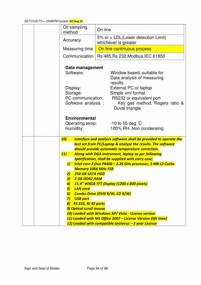
GETCO/E/TS – 2XMER01power/ R7 Aug 14
Sign and Seal of Bidder Page 84 of 98
Oil sampling method
On line
Accuracy 5% or + LDL(Lower detection Limit) whichever is greater
Measuring time On line continuous process
Communication Rs 485,Rs 232,Modbus,IEC 61850
Data management Software: Window based, suitable for Data analysis of measuring results. Display: External PC or laptop Storage: Simple xml format PC communication: RS232 or equivalent port Software analysis : Key gas method, Rogers ratio &
Duval triangle Environmental Operating temp: -10 to 55 deg. C Humidity: 100% RH, Non condensing
10) Interface and analysis software shall be provided to operate the
test set from PC/Laptop & analyze the results. The software
should provide automatic temperature correction.
11) Along with DGA instrument, laptop as per following
specification, shall be supplied with carry case;
1) Intel core 2 Duo P8400 – 2.26 GHz processor, 3 MB L2 Cache
Memory 1066 MHz FSB
2) 250 GB SATA HDD
3) 2 GB DDR2 RAM
4) 15.4” WXGA TFT Display (1200 x 800 pixels)
5) LAN card
6) Combo Drive (DVD R/W, CD R/W)
7) USB port
8) RS 232, RJ 45 ports
9) Optical scroll mouse
10) Loaded with Windows XP/ Vista - License version
11) Loaded with MS Office 2007 – License Version (life time)
12) Loaded with compatible antivirus – 3 year License
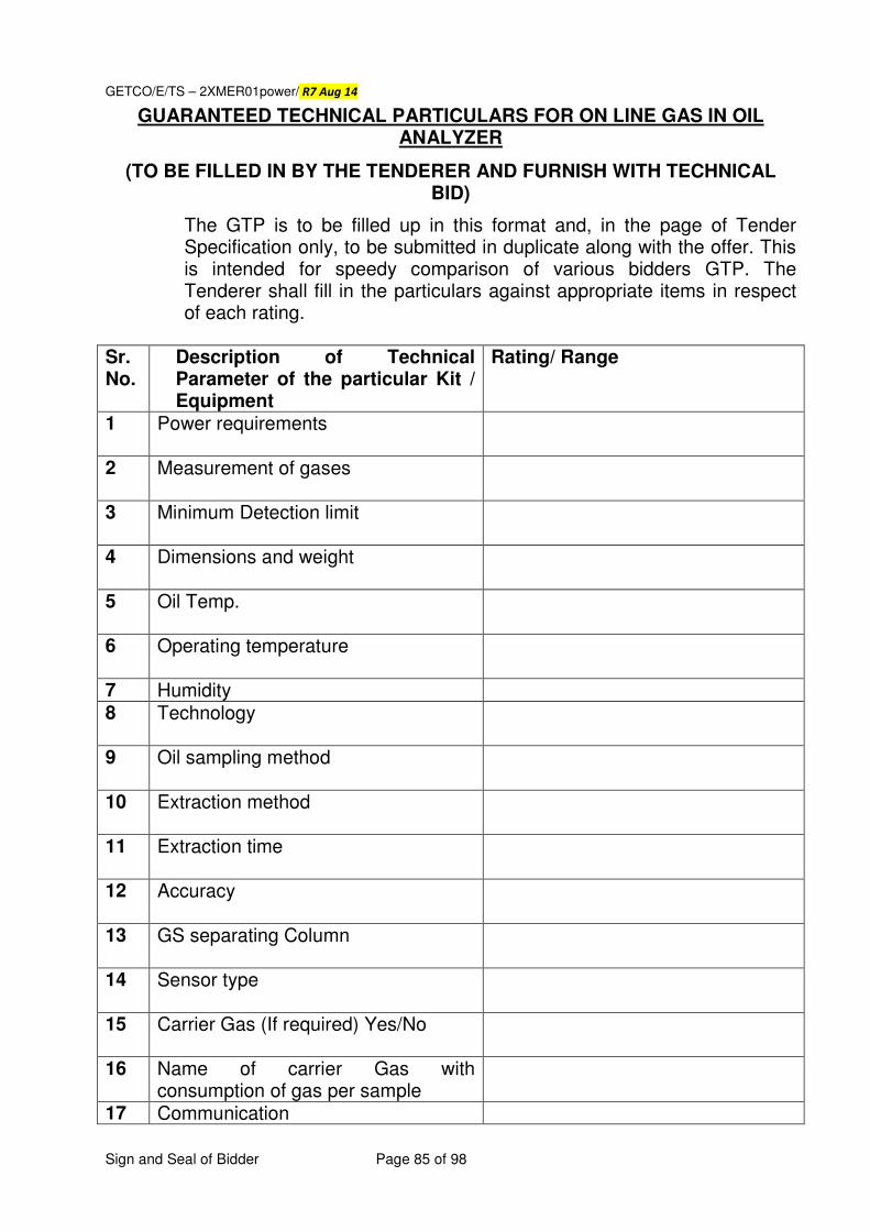
GETCO/E/TS – 2XMER01power/ R7 Aug 14
Sign and Seal of Bidder Page 85 of 98
GUARANTEED TECHNICAL PARTICULARS FOR ON LINE GAS IN OIL ANALYZER
(TO BE FILLED IN BY THE TENDERER AND FURNISH WITH TECHNICAL BID)
The GTP is to be filled up in this format and, in the page of Tender Specification only, to be submitted in duplicate along with the offer. This is intended for speedy comparison of various bidders GTP. The Tenderer shall fill in the particulars against appropriate items in respect of each rating.
Sr. No.
Description of Technical Parameter of the particular Kit / Equipment
Rating/ Range
1 Power requirements
2 Measurement of gases
3 Minimum Detection limit
4 Dimensions and weight
5 Oil Temp.
6 Operating temperature
7 Humidity 8 Technology
9 Oil sampling method
10 Extraction method
11 Extraction time
12 Accuracy
13 GS separating Column
14 Sensor type
15 Carrier Gas (If required) Yes/No
16 Name of carrier Gas with consumption of gas per sample
17 Communication
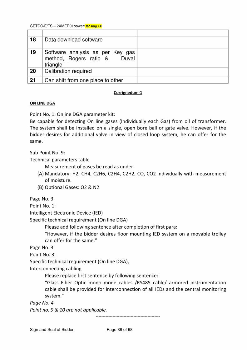
GETCO/E/TS – 2XMER01power/ R7 Aug 14
Sign and Seal of Bidder Page 86 of 98
18 Data download software
19 Software analysis as per Key gas method, Rogers ratio & Duval triangle
20 Calibration required
21 Can shift from one place to other
Corrignedum-1
ON LINE DGA
Point No. 1: Online DGA parameter kit:
Be capable for detecting On line gases (Individually each Gas) from oil of transformer.
The system shall be installed on a single, open bore ball or gate valve. However, if the
bidder desires for additional valve in view of closed loop system, he can offer for the
same.
Sub Point No. 9:
Technical parameters table
Measurement of gases be read as under
(A) Mandatory: H2, CH4, C2H6, C2H4, C2H2, CO, CO2 individually with measurement
of moisture.
(B) Optional Gases: O2 & N2
Page No. 3
Point No. 1:
Intelligent Electronic Device (IED)
Specific technical requirement (On line DGA)
Please add following sentence after completion of first para:
“However, if the bidder desires floor mounting IED system on a movable trolley
can offer for the same.”
Page No. 3
Point No. 3:
Specific technical requirement (On line DGA),
Interconnecting cabling
Please replace first sentence by following sentence:
“Glass Fiber Optic mono mode cables /RS485 cable/ armored instrumentation
cable shall be provided for interconnection of all IEDs and the central monitoring
system.”
Page No. 4
Point no. 9 & 10 are not applicable.
----------------------------------------------
GETCO/E/TS – 2XMER01power/ R7 Aug 14
Sign and Seal of Bidder Page 87 of 98
ANNEXURE - III
GUJARAT ENERGY TRANSMISSION CORPORATION LTD.
TECHNICAL SPECIFICATIONS FOR THE WORK OF DESIGN, SUPPLY, ERECTION
AND COMMISSIONING INCLUDING CIVIL WORK OF NITROGEN INJECTION
SYSTEM FOR PROTECTION AGAINST THE FIRE & EXPLOSION FOR
TRANSFORMER.
TECHNICAL SPECIFICATION NO.
GETCO/E/TS-FF/2902 DTD.JUNE 2008.
GETCO/E/TS – 2XMER01power/ R7 Aug 14
Sign and Seal of Bidder Page 88 of 98
TECHNICAL SPECIFICATIONS
Name of work: Turnkey contract for the work of design, supply, erection and
commissioning of Nitrogen Injection system for protection against the
transformer explosion for Transformers and Shunt Reactors as indicated in
Schedule – A. The scope of civil work for the same is in the bidder’s scope which includes all
required civil works including oil sump/tank, foundations etc., required for satisfactory working
of system. NIFPS supplier shall be Original Manufacturer (OEM) of system. The offered system has to
be designed, manufactured and tested as per relevant IS/IEC/ANSI standard with latest
amendments.
Each oil filled transformer / reactor shall be provided with a dedicated Nitrogen
Injection system for prevention against the transformer explosion which shall use nitrogen as quenching medium. The system shall prevent transformer / Reactor
oil tank explosion and possible fire in case of internal / external cause. In the
event of fire by external causes such as bushing fire. OLTC fires, fire from
surrounding equipment etc., it shall act as a fast and effective fire fighter. It shall accomplish its role as fire preventer and extinguisher without employing
water or carbon dioxide. Fire shall be extinguished within reasonable with time
(not more than 3 minutes so as not to harm the transformer) of system activation
and within 30 seconds (maximum) of commencement of nitrogen injection. The
system shall have been in successful operation / commissioned in Indian / Abroad installations for at least last five years for protection of transformers of 220 KV
and higher voltage class. The list of past supplies in India / Abroad along with
performance certificate from users of the system shall be submitted for approval
of purchaser.
Activation of the system
Mal-functioning of the Nitrogen injection system could lead to interruption in power supply. The supplier shall ensure that the probabilities of chances of
malfunctioning of the Nitrogen injection system are practically zero. To achieve
this objective, the supplier shall plan out scheme of activating signals which
should not be too complicated to make the system inoperative in case of actual need. The system shall be provided with automatic controls to prevent the
explosion of transformers. Besides automatic control, remote electrical push
button control at Control box and local manual control in the cubicle shall also be
provided. The following electrical-signals shall be used for activating the system under prevention mode/fire extinguishing mode.
Auto Mode
GETCO/E/TS – 2XMER01power/ R7 Aug 14
Sign and Seal of Bidder Page 89 of 98
For prevention:
• Differential relay operation.
• Buchholz relay paralleled with pressure relief valve or RPRR (Rapid Pressure Rise Relay)
• Tripping of all circuit breakers (on HV & LV/IV side) associated transformer / reactor is the pre-requisite for activation of system.
For extinguishing
• Fire Detector
• Buchholz relay paralleled with pressure relief valve or RPRR (Rapid Pressure
Rise Relay).
Tripping of all circuit breakers (on HV & LV/IV side) associated with transformer /
reactor is the pre-requisite for activation of system.
Manual Mode (Local / Remote)
Tripping of all circuit breakers (on HV & LV / IV side) associated with transformer
/ reactor is the pre-requisite for activation of system.
Manual Mode (Mechanical)
• Tripping of all circuit breakers (on HV & LV / IV side) associated with transformer / reactor is the pre-requisite for activation of system.
The system shall be designed to be operated manually in case of failure of power
supply to the system.
General description
Nitrogen Injection system should be a dedicated system for each oil filled transformer / reactor. It should have a Fire Extinguishing Cubicle (FEC) placed on
a plinth at a distance of 5-10 m away from transformer / reactor or placed next to
the firewall (if fire fighting wall exists). The FEC shall be connected to the top of
transformer / reactor oil tank for depressurization of tank and to the oil pit (steel tank) (capacity is approximately equal to 10% of total volume of oil in
transformer / reactor tank / or existing oil pit) from its bottom through oil pipes.
The FEC should house a pressurized nitrogen cylinder (s) which is connected to
the oil tank of transformer /reactor oil tank at bottom. The Transformer Conservator Isolation Valve (TCIV) is fitted between the conservator tank and
Buchholz relay. Cable connections are to be provided from signal box to the
control box in the control room, from control box to FEC and from TCIV to signal
GETCO/E/TS – 2XMER01power/ R7 Aug 14
Sign and Seal of Bidder Page 90 of 98
box. Detectors placed on the top of transformer / reactor tank are to be
connected in parallel to the signal box by Fire survival cables. Control box is also
to be connected to relay panel in control room for receiving system activation signals.
Operation
On receipt of all activating signals, the system shall drain - pre-determined
volume of hot oil from the top of tank (i.e. top oil layer), through outlet valve, to
reduce tank pressure by removing top oil and simultaneously injecting nitrogen
gas at high pressure for stirring the oil at pre-fixed rate and thus bringing the temperature of top oil layer down. Transformer conservator isolation valve blocks
the flow of oil from conservator tank in case of tank rupture / explosion or
bushing bursting. Nitrogen occupies the space created by oil drained out and
acts as an insulating layer over oil in the tank and thus preventing aggravation of fire.
System components
Nitrogen Injection system shall broadly consist of the following components.
However, all other components which are necessary for fast reliable and effective
working of the system shall deemed to be included in the scope of supply.
CUBICLE (FEC)
The Cubicle Frame shall be made of CRCA sheet of 3 mm (minimum) thick complete with the base frame, painted inside and outside with post office red
colour (shade 538 of IS -5). It shall have hugged / hinged split doors fitted with
high quality tamper proof lock. The doors, removable covers and panels shall be
gasketted all round with neoprene gaskets. The degree of protection shall be IP55. The following items shall be provided in the Cubicle.
• Nitrogen gas cylinder with regulator and falling pressure electrical contact manometer.
• Oil drain pipe with mechanical quick drain valve.
• Electro mechanical control equipment for draining of oil of pre-determined
volume and injecting regulated volume of nitrogen gas.
• Pressure monitoring switch for back-up protection for nitrogen release.
• Limit switches for monitoring of the system.
• Butterfly valve with flanges on the top of panel for connecting oil drain pipe and nitrogen injection pipes for transformer / reactors.
• Panel lighting (CFL Type)
GETCO/E/TS – 2XMER01power/ R7 Aug 14
Sign and Seal of Bidder Page 91 of 98
• Oil drain pipe extension of suitable sizes for connecting pipes to oil pit.
• Space heater.
Control box
Control box is to be placed in the control room for monitoring system operation, automatic control and remote operation. The following alarms, indications,
switches, push buttons, audio signal etc. shall be provided.
• System Oil.
• TCIV open.
• Oil drain valve closed.
• Gas inlet valve closed
• TCIV closed
• Detector trip
• Buchholz relay trip
• Oil drain valve open
• Extinction in progress
• Cylinder pressure low
• Differential relay trip
• PRV / RPRR trip
• Transformer / reactor trip
• System out of service
• Fault in cable connecting fault detector
• Fault in cable connecting differential relay
• Fault in cable connecting Buchholz relay
• Fault in cable connecting PRV / RPRR
• Fault in cable connecting transformer reactor trip
• Fault in cable connecting TCIV
• Auto / Manual / Off
• Extinction release on / off
• Lamp test
• Visual / Audio alarm for AC supply fail
• Visual / Audio alarm for DC supply fail
As far as possible the control box should be such devised that all the transformers and reactors or group thereof should be controlled from single spot. Potential
Free contacts shall be available for alarm troubles for input to SCADA system.
Also, separate hooter & emergency trip provision shall be provided in control
room over & above provided in control box (as control box is to be provided in
respective yard kiosk)
Transformer Conservator Isolation Valve.
GETCO/E/TS – 2XMER01power/ R7 Aug 14
Sign and Seal of Bidder Page 92 of 98
Transformer conservator isolation valve (TCIV) to be fitted in the conservator pipe
line, between conservator and buchholz relay which shall operate for isolating the conservator during abnormal flow of oil due to rupture / explosion of tank or
bursting of bushing. The valve shall not isolate conservator during normal flow of
oil during filtration or filling or refilling, locking plates to be provided with handle
for pad locking. It shall have proximity switch for remote alarm, indication with visual position indicator.
The TCIV should be of the best quality as malfunctioning of TCIV could lead to
serious consequence. The closing of TCIV means stoppage of breathing of transformer / reactor.
Locking plates shall be provided for pad locking.
Detectors
The system shall be complete with adequate number of detectors (quartz bulb)
fitted on the top cover of the transformer / reactor oil tank.
Signal box
It shall be mounted away from transformer / reactor main tank, preferably near
the transformer marshalling box, for terminating cable connections from TCIV & detectors and for further connection to be control box. The degree of protection
shall be IP55.
Cables
Fire survival cables (capable to withstand 750º C.) of 4 core x 1.5 sq. mm size for
connection of detectors in parallel shall be used. The fire survival cable shall
conform to BS 7629-1, BS 8434-1, BS 7629-1 and BS 5839-1, BS EN 50267-2-1 or relevant Indian standards.
Fire Retardant Low Smoke(FRLS) cable of adequate size shall be used for
connection of signal box / marshalling box near transformer / reactor and FEC mounted near transformer/ reactor with control box mounted in control room.
Fire Retardant Low Smoke (FRLS) cable of 4 core x 1.5 sq. mm size shall be used
for connection between control box to DC & AC supply source, FEC to AC supply source, signal box / marshalling box to transformer conservator isolation valve
connection on transformer / reactor. Separate cables for AC supply & DC supply
shall be used.
GETCO/E/TS – 2XMER01power/ R7 Aug 14
Sign and Seal of Bidder Page 93 of 98
Pipes
Pipes complete with connections, flanges, bends and tees etc. shall be supplied along with the system.
Other items to be supplied.
(a) Oil drain and nitrogen injection openings with gate valves on transformer /
reactor tank at suitable locations.
(b) Flanges between Buchholz relay and conservator tank for fixing TCIV.
(c ) Detector brackets on transformer / reactor tank top cover.
(d) Spare potential free contacts activating the system i.e. in differential relay,
Bucholz relay. Pressure Relief Device / RPRR , Circuit breaker of
transformer / reactor.
(e) Pipe connections between transformer / reactor and FEC and between FEC
and oil pit required for collecting top oil.
(f) Cabling for detectors mounted on transformer / reactor top cover.
(g) Inter cabling between signal box, control box and FEC.
(h) Butterfly valves / Gate valves on oil drain pipe and nitrogen injection pipe
which should be able to withstand full vacuum.
(i) Supports, signal box etc. which are to be painted with enameled paint.
(j) Any other item required for satisfactory operation of system.
Power supply
For Control Box 220 V / 110 V DC
For FEC Auxiliary 230 V AC
Spares for three (3) years Operation & Maintenance
The bidder apart from the below mentioned spares shall submit a list of
recommendation spares for three years trouble free operation of the equipments
and also furnish unit rates. The owners will scrutinize the said list and decide on
GETCO/E/TS – 2XMER01power/ R7 Aug 14
Sign and Seal of Bidder Page 94 of 98
the items on spares to be ordered and the quantities. These spares shall be
supplied by the contractor before end of guarantee period. The owner reserves
right to order the spares with twelve (12) months from the date of order for main equipments and the rate shall be kept valid till this date. The prices of these
spares shall not be considered for evaluation of the bid.
Mandatory Spares
Cylinder filled with Nitrogen of required 1 No.
Capacity per substation.
Detectors per transformer 3 No.
Regulator assembly per sub-station 1 No.
Modification on the transformer
No modification on the transformer shall be allowed which affects its performance
(i.e. efficiency, losses, heat dissipation ability etc.) safety, life etc. or it’s any other useful parameter. This requirement shall be paramount importance and
shall form the essence of the contract.
However, in any case, performance of transformer should not be affected in any
manner by having Nitrogen Injection Fire Prevention Cum Extinguishing System (NIFPES) and the Contractor / Sub-Contractor shall give an undertaking to this
effect. All pipes should be washed / rinsed with transformer oil. If any damage is
done to the transformer and / or any connected equipment during installation &
commissioning full recovery therefore shall be effected from the Contractor / Sub-Contractor, of NIFPES system.
It shall be solely the responsibility of Contractor / Sub-Contractor to install, carry
out pre-commissioning tests & commission NIFPES at the mentioned Sub-Station in this specification, to the entire satisfaction of the GETCO.
Interlocks
It shall be ensured that once the NIFPES gets activated manually or in auto
mode, all the connected breakers shall not close until the system is actually put in
OFF mode. Also PRV shall get closed only if all the connected breakers are open.
GETCO/E/TS – 2XMER01power/ R7 Aug 14
Sign and Seal of Bidder Page 95 of 98
Tests
Contractor has to submit valid type test reports as per relevant IS/IEC.
including IP 55 on FEC, control box etc., from NABL approved Laboratory or any
other reputed authority nationally or internationally not older than 5 years &
must be valid till expiry of validity of offer.
Reports of all routine test conducted as per relevant IS/IEC standards in respect
of various bought out items including test reports for degree of protection for FEC / control box / signal box shall be submitted by the supplier.
The supplier shall demonstrate the entire functional test associated with the
following as Factory Acceptance Tests:
• FEC, Control Box
• Fire Detector
• Transformer Conservator Isolation Valve
The performance test of the complete system shall be carried out after erection of
the system with transformer at site.
Detailed layout drawings, equipment drawing along with 4 sets of Operation and
Maintenance manual along with soft copies (In CDs) shall be submitted by the
supplier along with the consignment.
The guaranteed and other technical particulars for the offered system are
indicated in Section - "Guaranteed and Other Technical Particulars". Any
other particulars considered necessary in addition to those listed in that Section may be furnished by the Bidder.
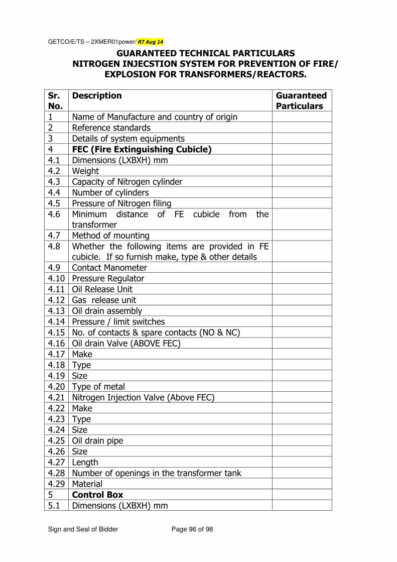
GETCO/E/TS – 2XMER01power/ R7 Aug 14
Sign and Seal of Bidder Page 96 of 98
GUARANTEED TECHNICAL PARTICULARS
NITROGEN INJECSTION SYSTEM FOR PREVENTION OF FIRE/
EXPLOSION FOR TRANSFORMERS/REACTORS.
Sr.
No.
Description Guaranteed
Particulars
1 Name of Manufacture and country of origin
2 Reference standards
3 Details of system equipments
4 FEC (Fire Extinguishing Cubicle)
4.1 Dimensions (LXBXH) mm
4.2 Weight
4.3 Capacity of Nitrogen cylinder
4.4 Number of cylinders
4.5 Pressure of Nitrogen filing
4.6 Minimum distance of FE cubicle from the
transformer
4.7 Method of mounting
4.8 Whether the following items are provided in FE
cubicle. If so furnish make, type & other details
4.9 Contact Manometer
4.10 Pressure Regulator
4.11 Oil Release Unit
4.12 Gas release unit
4.13 Oil drain assembly
4.14 Pressure / limit switches
4.15 No. of contacts & spare contacts (NO & NC)
4.16 Oil drain Valve (ABOVE FEC)
4.17 Make
4.18 Type
4.19 Size
4.20 Type of metal
4.21 Nitrogen Injection Valve (Above FEC)
4.22 Make
4.23 Type
4.24 Size
4.25 Oil drain pipe
4.26 Size
4.27 Length
4.28 Number of openings in the transformer tank
4.29 Material
5 Control Box
5.1 Dimensions (LXBXH) mm
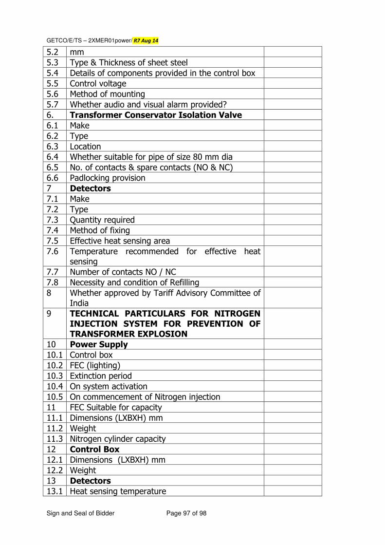
GETCO/E/TS – 2XMER01power/ R7 Aug 14
Sign and Seal of Bidder Page 97 of 98
5.2 mm
5.3 Type & Thickness of sheet steel
5.4 Details of components provided in the control box
5.5 Control voltage
5.6 Method of mounting
5.7 Whether audio and visual alarm provided?
6. Transformer Conservator Isolation Valve
6.1 Make
6.2 Type
6.3 Location
6.4 Whether suitable for pipe of size 80 mm dia
6.5 No. of contacts & spare contacts (NO & NC)
6.6 Padlocking provision
7 Detectors
7.1 Make
7.2 Type
7.3 Quantity required
7.4 Method of fixing
7.5 Effective heat sensing area
7.6 Temperature recommended for effective heat
sensing
7.7 Number of contacts NO / NC
7.8 Necessity and condition of Refilling
8 Whether approved by Tariff Advisory Committee of
India
9 TECHNICAL PARTICULARS FOR NITROGEN
INJECTION SYSTEM FOR PREVENTION OF
TRANSFORMER EXPLOSION
10 Power Supply
10.1 Control box
10.2 FEC (lighting)
10.3 Extinction period
10.4 On system activation
10.5 On commencement of Nitrogen injection
11 FEC Suitable for capacity
11.1 Dimensions (LXBXH) mm
11.2 Weight
11.3 Nitrogen cylinder capacity
12 Control Box
12.1 Dimensions (LXBXH) mm
12.2 Weight
13 Detectors
13.1 Heat sensing temperature
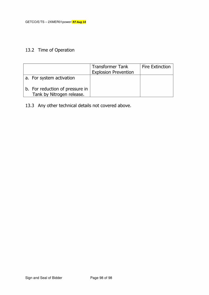
GETCO/E/TS – 2XMER01power/ R7 Aug 14
Sign and Seal of Bidder Page 98 of 98
13.2 Time of Operation
Transformer Tank
Explosion Prevention
Fire Extinction
a. For system activation
b. For reduction of pressure in Tank by Nitrogen release.
13.3 Any other technical details not covered above.


![Retain for future use - tecnical.cat€¦ · [1.13 USER MENU] (USr-)_____ 202 [1.14 PROGRAMMABLE CARD] (PLC-) _____ 203 ... Communication Parameters Manual This manual describes:](https://img.pdfslide.us/doc/110x75/607dc0691fe3305dd75b828b/retain-for-future-use-113-user-menu-usr-202-114-programmable-card.jpg)


![APPLICATION IN PET RADIOCHEMISTRY. - Politecnico di … · 1.5.2 Nucleophilic fluorination ... Figure 1.13. [18F]FECH and [11C]Choline uptake mechanism . Figure 1.14. Radiolabelled](https://img.pdfslide.us/doc/110x75/5af4e91e7f8b9a190c8da922/application-in-pet-radiochemistry-politecnico-di-nucleophilic-fluorination.jpg)