Embed Size (px)
Citation preview

INS
TRU
CTIO
NM
AN
UA
L16" Variable Speed Scroll Saw
with Quickset II® BladeChanging Feature
(Model SS250)
PART NO. 905574 - 05-03-02Copyright © 2002 Delta Machinery
ESPAÑOL: PÁGINA 21To learn more about DELTA MACHINERY visit our website at: www.deltamachinery.com.For Parts, Service, Warranty or other Assistance,
please call 1-800-223-7278 (In Canada call 1-800-463-3582).

2
GENERAL SAFETY RULESWoodworking can be dangerous if safe and proper operating procedures are not followed. As with all machinery, thereare certain hazards involved with the operation of the product. Using the machine with respect and caution willconsiderably lessen the possibility of personal injury. However, if normal safety precautions are overlooked or ignored,personal injury to the operator may result. Safety equipment such as guards, push sticks, hold-downs, featherboards,goggles, dust masks and hearing protection can reduce your potential for injury. But even the best guard won’t makeup for poor judgment, carelessness or inattention. Always use common sense and exercise caution in the workshop.If a procedure feels dangerous, don’t try it. Figure out an alternative procedure that feels safer. REMEMBER: Yourpersonal safety is your responsibility.
This machine was designed for certain applications only. Delta Machinery strongly recommends that this machine notbe modified and/or used for any application other than that for which it was designed. If you have any questions relativeto a particular application, DO NOT use the machine until you have first contacted Delta to determine if it can or shouldbe performed on the product.
Technical Service ManagerDelta Machinery4825 Highway 45 NorthJackson, TN 38305
(IN CANADA: 505 SOUTHGATE DRIVE, GUELPH, ONTARIO N1H 6M7)
WARNING: FAILURE TO FOLLOW THESE RULES MAY RESULT IN SERIOUS PERSONAL INJURY
1. FOR YOUR OWN SAFETY, READ INSTRUCTIONMANUAL BEFORE OPERATING THE TOOL. Learn thetool’s application and limitations as well as the specifichazards peculiar to it.
2. KEEP GUARDS IN PLACE and in working order.3. ALWAYS WEAR EYE PROTECTION. Wear safety
glasses. Everyday eyeglasses only have impact resistantlenses; they are not safety glasses. Also use face or dustmask if cutting operation is dusty. These safety glassesmust conform to ANSI Z87.1 requirements. NOTE:Approved glasses have Z87 printed or stamped on them.
4. REMOVE ADJUSTING KEYS AND WRENCHES. Formhabit of checking to see that keys and adjusting wrenchesare removed from tool before turning it “on”.
5. KEEP WORK AREA CLEAN. Cluttered areas andbenches invite accidents.
6. DON’T USE IN DANGEROUS ENVIRONMENT. Don’tuse power tools in damp or wet locations, or expose themto rain. Keep work area well-lighted.
7. KEEP CHILDREN AND VISITORS AWAY. All childrenand visitors should be kept a safe distance from work area.
8. MAKE WORKSHOP CHILDPROOF – with padlocks,master switches, or by removing starter keys.
9. DON’T FORCE TOOL. It will do the job better and besafer at the rate for which it was designed.10. USE RIGHT TOOL. Don’t force tool or attachment todo a job for which it was not designed.11. WEAR PROPER APPAREL. No loose clothing, gloves,neckties, rings, bracelets, or other jewelry to get caught inmoving parts. Nonslip footwear is recommended. Wearprotective hair covering to contain long hair.12. SECURE WORK. Use clamps or a vise to hold workwhen practical. It’s safer than using your hand and freesboth hands to operate tool.13. DON’T OVERREACH . Keep proper footing andbalance at all times.14. MAINTAIN TOOLS IN TOP CONDITION. Keep toolssharp and clean for best and safest performance. Followinstructions for lubricating and changing accessories.15. DISCONNECT TOOLS before servicing and whenchanging accessories such as blades, bits, cutters, etc.16. USE RECOMMENDED ACCESSORIES. The use ofaccessories and attachments not recommended by Deltamay cause hazards or risk of injury to persons.17. REDUCE THE RISK OF UNINTENTIONAL STARTING.Make sure switch is in “OFF” position before plugging inpower cord. In the event of a power failure, move switchto the “OFF” position.
18. NEVER STAND ON TOOL. Serious injury could occur ifthe tool is tipped or if the cutting tool is accidentallycontacted.19. CHECK DAMAGED PARTS. Before further use of thetool, a guard or other part that is damaged should becarefully checked to ensure that it will operate properly andperform its intended function – check for alignment ofmoving parts, binding of moving parts, breakage of parts,mounting, and any other conditions that may affect itsoperation. A guard or other part that is damaged should beproperly repaired or replaced.20. DIRECTION OF FEED. Feed work into a blade orcutter against the direction of rotation of the blade or cutteronly.21. NEVER LEAVE TOOL RUNNING UNATTENDED.TURN POWER OFF. Don’t leave tool until it comes to acomplete stop.22. STAY ALERT, WATCH WHAT YOU ARE DOING, ANDUSE COMMON SENSE WHEN OPERATING A POWERTOOL. DO NOT USE TOOL WHILE TIRED OR UNDERTHE INFLUENCE OF DRUGS, ALCOHOL, ORMEDICATION. A moment of inattention while operatingpower tools may result in serious personal injury.23. MAKE SURE TOOL IS DISCONNECTED FROMPOWER SUPPLY whi le motor is be ing mounted,connected or reconnected.24. THE DUST GENERATED by certain woods and woodproducts can be injurious to your health. Always operatemachinery in well ventilated areas and provide for properdust removal. Use wood dust collection systems wheneverpossible.25. WARNING: SOME DUST CREATED BYPOWER SANDING, SAWING, GRINDING, DRILLING,AND OTHER CONSTRUCTION ACTIVITIES containschemicals known to cause cancer, birth defects or otherreproductive harm. Some examples of these chemicalsare:· lead from lead-based paints,· crystalline silica from bricks and cement and other
masonry products, and· arsenic and chromium from chemically-treated lumber. Your risk from these exposures varies, depending on howoften you do this type of work. To reduce your exposureto these chemicals: work in a well ventilated area, andwork with approved safety equipment, such as thosedust masks that are specially designed to filter outmicroscopic particles.
SAVE THESE INSTRUCTIONS. Refer to them often and use them to instruct others.

ADDITIONAL SAFETY RULES FORSCROLL SAWS
3
WARNING: FAILURE TO FOLLOW THESE RULES MAY RESULT IN SERIOUS PERSONAL INJURY.
SAVE THESE INSTRUCTIONS. Refer to them often
and use them to instruct others.
1. DO NOT OPERATE your scroll saw until it iscompletely assembled and installed according to theinstructions.2. IF YOU ARE NOT thoroughly familiar with the
operation of Scroll Saws, obtain advice from yoursupervisor, instructor or other qualified person.3. YOUR SCROLL SAW MUST be securely fastened
to a stand or workbench. If there is any tendency for thestand or workbench to move during operation, the standor workbench MUST be fastened to the floor.4. THIS SCROLL SAW is intended for indoor use only.5. MAKE SURE blade is properly tensioned before
operating saw.6. TO AVOID blade breakage ALWAYS adjust blade
tension correctly.7. MAKE SURE the blade teeth point downward
toward the table.8. NEVER turn the saw "ON" before clearing the table
of all objects (tools, scraps of wood, etc.).9. DO NOT cut material that is too small to be safely
supported.10. AVOID awkward hand positions where a sudden slipcould cause a hand to move into the blade.11. ALWAYS keep hands and fingers away from blade.12. ALWAYS adjust holddown foot for each newoperation.13. DO NOT USE dull or bent blades.14. DO NOT attempt to saw material that does not havea flat surface, unless a suitable support is used.15. MAKE "relief" cuts before cutting long curves.16. NEVER attempt to cut a curve that is too tight forthe blade being used.17. WHEN backing a blade out of a workpiece, theblade may bind in the saw kerf. This is usually caused bysawdust in the kerf. If this happens, turn "OFF" theswitch and remove plug from power source outlet.Wedge open the kerf and back blade out of theworkpiece.18. THE USE of attachments and accessories notrecommended by Delta may result in the risk of injuries.19. ALWAYS hold the work firmly against the table.20. DO NOT feed the material too fast while cutting.Only feed the material fast enough so that the blade willcut.
21. NEVER start the Scroll Saw with the stock pressedagainst the blade.22. WHEN cutting a large workpiece MAKE SURE thematerial is supported at table height.23. USE CAUTION when cutting material which isirregular in cross section which could pinch the bladebefore the cut is completed. A piece of moulding forexample must lay flat on the table and not be permittedto rock while being cut.24. USE CAUTION when cutting round material such asdowel rods or tubing. They have a tendency to roll whilebeing cut causing the blade to "bite." Use a V-block tocontrol the piece.25. ALWAYS release blade tension before removing theblade from the upper or lower blade holders.26. MAKE CERTAIN table tilting lock is tightenedbefore starting the machine.27. NEVER reach under the table while the machine isrunning.28. NEVER perform layout, assembly or set-up work onthe table while the saw is operating.29. ALWAYS STOP the saw before removing scrappieces from the table.30. WHEN THE TOOL IS NOT IN USE, the switchshould be locked in the “OFF” position to preventunauthorized use.31. SHOULD any part of your Scroll Saw be missing,damaged or fail in any way, or any electrical componentfail to perform properly, shut off switch and remove plugfrom power supply outlet. Replace missing, damaged orfailed parts before resuming operation.32. ADDITIONAL INFORMATION regarding the safeand proper operation of this product is available fromthe National Safety Council, 1121 Spring Lake Drive,Itasca, IL 60143-3201, in the Accident PreventionManual for Industrial Operations and also in the SafetyData Sheets provided by the NSC. Please also refer tothe American National Standards Institute ANSI 01.1Safety Requirements for Woodworking Machinery andthe U.S. Department of Labor OSHA 1910.213Regulations.
4
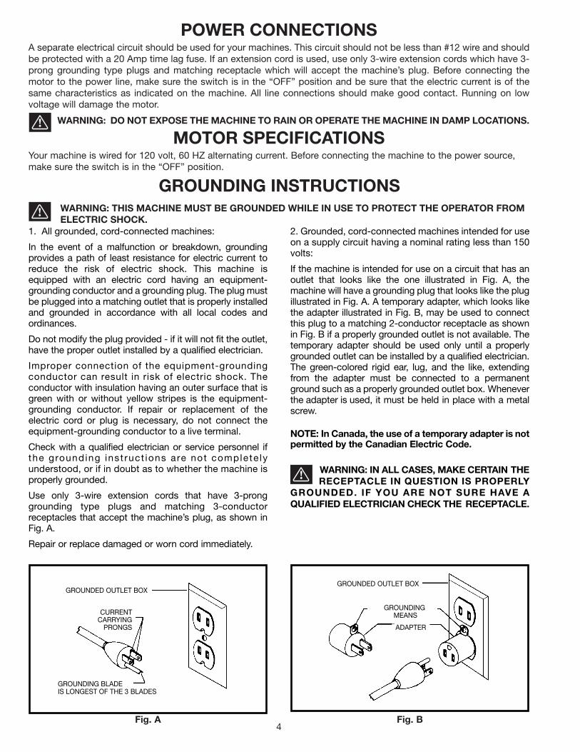
POWER CONNECTIONSA separate electrical circuit should be used for your machines. This circuit should not be less than #12 wire and shouldbe protected with a 20 Amp time lag fuse. If an extension cord is used, use only 3-wire extension cords which have 3-prong grounding type plugs and matching receptacle which will accept the machine’s plug. Before connecting themotor to the power line, make sure the switch is in the “OFF” position and be sure that the electric current is of thesame characteristics as indicated on the machine. All line connections should make good contact. Running on lowvoltage will damage the motor.
WARNING: DO NOT EXPOSE THE MACHINE TO RAIN OR OPERATE THE MACHINE IN DAMP LOCATIONS.
MOTOR SPECIFICATIONSYour machine is wired for 120 volt, 60 HZ alternating current. Before connecting the machine to the power source,make sure the switch is in the “OFF” position.
GROUNDING INSTRUCTIONSWARNING: THIS MACHINE MUST BE GROUNDED WHILE IN USE TO PROTECT THE OPERATOR FROMELECTRIC SHOCK.
Fig. A Fig. B
GROUNDED OUTLET BOX
CURRENTCARRYING
PRONGS
GROUNDING BLADEIS LONGEST OF THE 3 BLADES
GROUNDED OUTLET BOX
GROUNDINGMEANS
ADAPTER
2. Grounded, cord-connected machines intended for useon a supply circuit having a nominal rating less than 150volts:
If the machine is intended for use on a circuit that has anoutlet that looks like the one illustrated in Fig. A, themachine will have a grounding plug that looks like the plugillustrated in Fig. A. A temporary adapter, which looks likethe adapter illustrated in Fig. B, may be used to connectthis plug to a matching 2-conductor receptacle as shownin Fig. B if a properly grounded outlet is not available. Thetemporary adapter should be used only until a properlygrounded outlet can be installed by a qualified electrician.The green-colored rigid ear, lug, and the like, extendingfrom the adapter must be connected to a permanentground such as a properly grounded outlet box. Wheneverthe adapter is used, it must be held in place with a metalscrew.
NOTE: In Canada, the use of a temporary adapter is notpermitted by the Canadian Electric Code.
WARNING: IN ALL CASES, MAKE CERTAIN THE RECEPTACLE IN QUESTION IS PROPERLY
GROUNDED. IF YOU ARE NOT SURE HAVE AQUALIFIED ELECTRICIAN CHECK THE RECEPTACLE.
1. All grounded, cord-connected machines:
In the event of a malfunction or breakdown, groundingprovides a path of least resistance for electric current toreduce the risk of electric shock. This machine isequipped with an electric cord having an equipment-grounding conductor and a grounding plug. The plug mustbe plugged into a matching outlet that is properly installedand grounded in accordance with all local codes andordinances.
Do not modify the plug provided - if it will not fit the outlet,have the proper outlet installed by a qualified electrician.
Improper connection of the equipment-groundingconductor can result in risk of electric shock. Theconductor with insulation having an outer surface that isgreen with or without yellow stripes is the equipment-grounding conductor. If repair or replacement of theelectric cord or plug is necessary, do not connect theequipment-grounding conductor to a live terminal.
Check with a qualified electrician or service personnel ifthe grounding inst ruct ions are not complete lyunderstood, or if in doubt as to whether the machine isproperly grounded.
Use only 3-wire extension cords that have 3-pronggrounding type plugs and matching 3-conductorreceptacles that accept the machine’s plug, as shown inFig. A.
Repair or replace damaged or worn cord immediately.

Use proper extension cords. Make sure your extension cord is in good condition and is a 3-wire extension cord whichhas a 3-prong grounding type plug and matching receptacle which will accept the machine’s plug. When using anextension cord, be sure to use one heavy enough to carry the current of the machine. An undersized cord will causea drop in line voltage, resulting in loss of power and overheating. Fig. D, shows the correct gauge to use dependingon the cord length. If in doubt, use the next heavier gauge. The smaller the gauge number, the heavier the cord.
EXTENSION CORDS
OPERATING INSTRUCTIONSFOREWORD
Delta ShopMaster Model SS250 is a 16" variable speed scroll saw. The variable speed range for the Model SS250 is400-1800 cutting strokes per minute. The Model SS250 offers a full 2" depth of cut for thick workpieces.
UNPACKING AND CLEANINGCarefully unpack the machine and all loose items from the shipping container(s). Remove the protective coating fromall unpainted surfaces. This coating may be removed with a soft cloth moistened with kerosene (do not use acetone,gasoline or lacquer thinner for this purpose). After cleaning, cover the unpainted surfaces with a good quality householdfloor paste wax.
NOTICE: THE MANUAL COVER PHOTO ILLUSTRATES THE CURRENTPRODUCTION MODEL. ALL OTHER ILLUSTRATIONS ARE REPRESENTATIVE
ONLY AND MAY NOT DEPICT THE ACTUAL COLOR, LABELING ORACCESSORIES AND MAY BE INTENDED TO ILLUSTRATE TECHNIQUE ONLY.
5
Fig. D
MINIMUM GAUGE EXTENSION CORDRECOMMENDED SIZES FOR USE WITH STATIONARY ELECTRIC MACHINES
Ampere Total Length Gauge ofRating Volts of Cord in Feet Extension Cord
0-6 120 up to 25 18 AWG0-6 120 25-50 16 AWG0-6 120 50-100 16 AWG0-6 120 100-150 14 AWG
6-10 120 up to 25 18 AWG6-10 120 25-50 16 AWG6-10 120 50-100 14 AWG6-10 120 100-150 12 AWG
10-12 120 up to 25 16 AWG10-12 120 25-50 16 AWG10-12 120 50-100 14 AWG10-12 120 100-150 12 AWG
12-16 120 up to 25 14 AWG12-16 120 25-50 12 AWG12-16 120 GREATER THAN 50 FEET NOT RECOMMENDED

6
SCROLL SAW PARTS
Fig. 1 Fig. 2
Fig. 1
1. Scroll Saw with blade attached
1
Fig. 2
2. Table
3. Quickset Blade Changing Wrench
4. Holddown Rod
5. 4mm Hex Wrench
6. Locking Handle
7. M10 Flat Washer
8. Blank Table Insert
9. Table Insert
10. Special Screw M6x1x45mm (2)
11. M6 Locknut (2)
2
34
5
6 78
9
10 11

7
ASSEMBLY1. Remove the blade from the scroll saw.
2. Move the blade lever tension handle (A) Fig. 3, to theforeword position as shown.
3. Push chuck locking lever (B) Fig. 4 to the rear asshown. This will release the blade (C) from the upperchuck assembly (D).
4. Insert long end (F) Fig. 5, of quickset blade changingwrench into hole (G) in lower blade holder. This will alignwrench (H) with blade holder screw (J). Turn wrench (H)counter-clockwise. This will release the blade from thelower chuck assembly.
Fig. 3
A
Fig. 4
B C
D
Fig. 5
FG
HJ

8
Fig. 7
5. Position table (A) Fig. 7, on the machine as shown.Align the two holes in the table trunnions (O) with thetwo holes in the base (P) of the machine. NOTE:BEFORE TIGHTENING THE M6x1x45mm SPECIALSCREWS (B) AND M6 LOCKNUTS (C) FIG. 7, MAKESURE THE TILT SCALE (D) FIG. 7, IS POSITIONEDINSIDE POINTER (E) AS SHOWN. ALSO, DO NOTCOMPLETELY TIGHTEN THE M6x1x45mm SPECIALSCREWS (B) AND M6 LOCKNUTS (C). TABLE MUSTBE ABLE TO TILT FREELY. Fasten the table (A) Fig. 7,to the base (P), using the two M6x1x45mm specialscrews (B), and M6 locknuts (C) as shown.
6. Disassemble the handle by unscrewing and remov-ing screw and spring (F), and handle (G) from lockingstud (H), as shown in Fig. 8. Place a M10 flat washer (J)on threaded end of stud (H).
7. Screw threaded end of stud (H) Fig. 9, with the M10flat washer (J) through slot in angle of tilt scale (D) andinto tapped hole (K).
8. Place handle (G) Fig. 10, onto locking stud (H) andfasten with screw and spring (F). Move table (A) to thehorizontal position and lock table (A), by turning handle(G) clockwise.
B
P
OC
AC
O
BP
Fig. 8
F
G
H
J
Fig. 9
Fig. 10
GF
H
A
D
E
J
H
D
K

9
9. Using the 4mm wrench (L) Fig. 11, loosen the twoscrews (P) on bottom of bracket (M) that fasten bracketto rod (N).
Fig. 11
Fig. 12
10. Rotate bracket (M), to the position shown in Fig. 12.Loosen lock handle (R) and insert holddown rod (S) intohole in bracket (M), as shown.
R
M S
11. Rotate bracket (M) Fig. 13, back to its originalposition as shown, and tighten the two screws thatwere loosened in STEP 9. Then tighten lockhandle (R) tohold rod (S) in position.
Fig. 13
MN
S
R
12. Slide end of chip blower tube (T) Fig. 14, onto end ofair nozzle (V), as shown.
Fig. 14
T
V
Fig. 15
13. The tool holder (X) Fig. 15, is used to hold thequickset blade changing wrench (Y), (for removing bladefrom lower blade holder), 4mm allen wrench (W) andextra blades (Z).
X
YW
Z
NM
P
L

10
FASTENING SCROLL SAWTO SUPPORTING SURFACEYour scroll saw MUST be securely fastened to a standor workbench using the holes in the four rubber feet,three of which are shown at (A) Fig. 16. IMPORTANT:When mounting the saw to a stand or workbench DONOT over-tighten mounting bolts. Leave some cushionin the four rubber feet (A) for absorbing noise andvibration.
An alternate method of securing the scroll saw is toclamp the front and side ledges of the scroll saw to asupporting surface with C-clamps.
IMPORTANT: If there is any tendency for the stand orworkbench to move during operation, the stand or work-bench must be fastened to the floor.
Fig. 16
AA
OPERATING CONTROLS AND ADJUSTMENTS
ON-OFF AND VARIABLESPEED SWITCHESThe on-off switch (A) Fig. 17, and variable speed switch(B) is located on the right side of the scroll saw base, asshown. To turn the saw "ON," push the switch (A) up tothe “ON” position. To turn the saw "OFF", push theswitch (A) down to the “OFF” position.
The scroll saw is equiped with a variable speed controllknob (B) Fig. 17. The variable speed range is 400 to1800 strokes per minute. When the variable speed knob(B) Fig. 17, is rotated all the way to the left(counterclockwise) the speed will be 400 strokes perminute. To increase the speed, rotate knob (B) to theright (clockwise) until the desired speed is obtained.When the knob (B) is rotated all the way to the right(clockwise) the speed will be 1800 strokes per minute.
Fig. 17
AB
LOCKING ON-OFF SWITCHIN THE "OFF" POSITIONIMPORTANT: When the machine is not in use, the switchshould be locked in the OFF position using a padlock (C)Fig. 18, with a 3/16" diameter shackle to preventunauthorized use.
Fig. 18
C

11
TABLE INSERT
The table insert (A) can be assembled to the saw tablewith the opening in the insert pointing to the front of thetable, as shown in Fig. 19, or to the right as shown in Fig.20.
With the table in the level position, 90 degrees to theblade, the insert (A) should be positioned, as shown inFig. 19. This allows for the blade to be pivoted forwardafter it is unclamped from the top blade holder, enablingyou to quickly insert the blade into the next hole in apattern when doing inside-cutting.
When tilting the table for bevel cutting operations theinsert (A) should be positioned as shown in Fig. 20. Thisallows for clearance of the blade when the table is tilting.
Fig. 19
Fig. 20
A
A
Fig. 21
AB
A table insert blank (B) Fig. 21, is supplied as standardequipment with your scroll saw and can be used whencutting very small workpieces to give added support tothe bottom of the workpiece. Cut a slot into the blankand replace the standard insert (A) with the blank (B).The slot cut into the blank (B) will only be as wide as theblade giving maximum support to the bottom of theworkpiece.
CHANGING BLADES
1. DISCONNECT MACHINE FROM POWER SOURCE.
2. Remove table insert (A) Fig. 22, and release bladetension by pulling tension lever (B) forward, as shown. A
B
Fig. 22

12
3. Push chuck locking lever (C) Fig. 23, to the rear asshown. This will release the blade (D) from the upperchuck (E).
Fig. 23
CD
E
4. Insert long end (F) Fig. 24, of quickset blade wrenchinto hole (G) in lower blade holder. This will align wrench(H) with blade holder screw (J).
Fig. 24
GF
JH
5. Fig. 25 illustrates the quickset blade changingwrench (K) engaged with the lower blade holderassembly. Turn wrench counterclockwise to loosenscrew (J) Figs. 24 and 25, and remove blade from lowerchuck.
6. Insert new blade into the lower and upper bladeholders in the same manner, making certain the bladeteeth are pointing down toward the table.
7. Tighten screw (J) Fig. 26, in lower blade guardassembly.
8. Push chuck locking lever (C) Fig. 23, to the forewordposition, to lock the blade in the upper blade holderassembly.
10. Apply blade tension by referring to the followingsection "ADJUSTING BLADE TENSION."
Fig. 25
Fig. 26
K
J
J
9. Replace the table insert that was removed in STEP2.
13
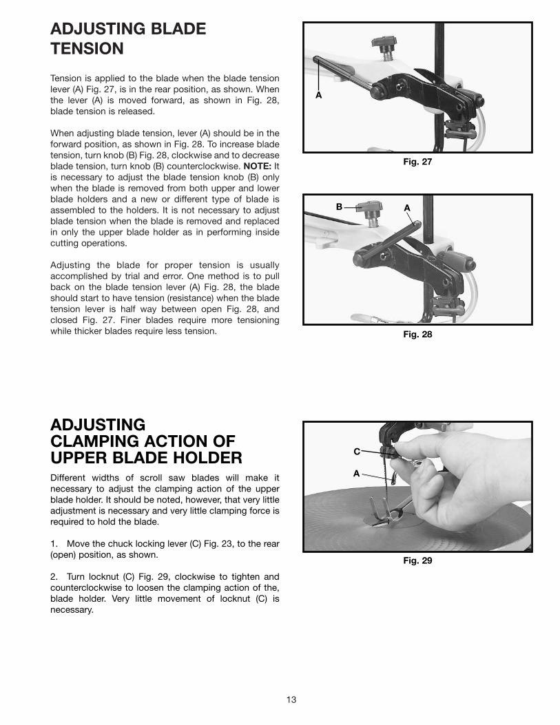
ADJUSTING BLADETENSION
Tension is applied to the blade when the blade tensionlever (A) Fig. 27, is in the rear position, as shown. Whenthe lever (A) is moved forward, as shown in Fig. 28,blade tension is released.
When adjusting blade tension, lever (A) should be in theforward position, as shown in Fig. 28. To increase bladetension, turn knob (B) Fig. 28, clockwise and to decreaseblade tension, turn knob (B) counterclockwise. NOTE: Itis necessary to adjust the blade tension knob (B) onlywhen the blade is removed from both upper and lowerblade holders and a new or different type of blade isassembled to the holders. It is not necessary to adjustblade tension when the blade is removed and replacedin only the upper blade holder as in performing insidecutting operations.
Adjusting the blade for proper tension is usuallyaccomplished by trial and error. One method is to pullback on the blade tension lever (A) Fig. 28, the bladeshould start to have tension (resistance) when the bladetension lever is half way between open Fig. 28, andclosed Fig. 27. Finer blades require more tensioningwhile thicker blades require less tension.
Fig. 27
Fig. 28
A
AB
ADJUSTINGCLAMPING ACTION OFUPPER BLADE HOLDERDifferent widths of scroll saw blades will make itnecessary to adjust the clamping action of the upperblade holder. It should be noted, however, that very littleadjustment is necessary and very little clamping force isrequired to hold the blade.
1. Move the chuck locking lever (C) Fig. 23, to the rear(open) position, as shown.
2. Turn locknut (C) Fig. 29, clockwise to tighten andcounterclockwise to loosen the clamping action of the,blade holder. Very little movement of locknut (C) isnecessary.
Fig. 29
A
C

14
Fig. 30
Fig. 31
TILTING THE TABLEThe table on your scroll saw can be tilted 45 degrees tothe left for bevel cutting operations by loosening tablelock handle (A) Fig. 30, tilt the table to the desired angleand tighten lock handle (A).
When bevel cutting, the holddown (B) Fig. 31, can beadjusted to lay flat on the stock by loosening screw (C)and tilting the holddown (B) accordingly. Then tightenscrew (C).
A
ADJUSTING THE TABLE
Fig. 32
Fig. 33
1. Loosen the table locking handle, and move the tableall the way to the right.
2. Using a square (A) Fig. 32, check to see if the tableis 90 degrees to the saw blade, as shown.
3. If the table is not at 90 degrees to the blade, adjustthe table accordingly making certain screw (B) Fig. 33,contacts bottom of table surface when table is 90degrees to the blade. Screw (B) can be adjusted byloosening nut (C), thread screw (B) in or out the desireddistance and tighten nut (C).
A
B
C
C B
15
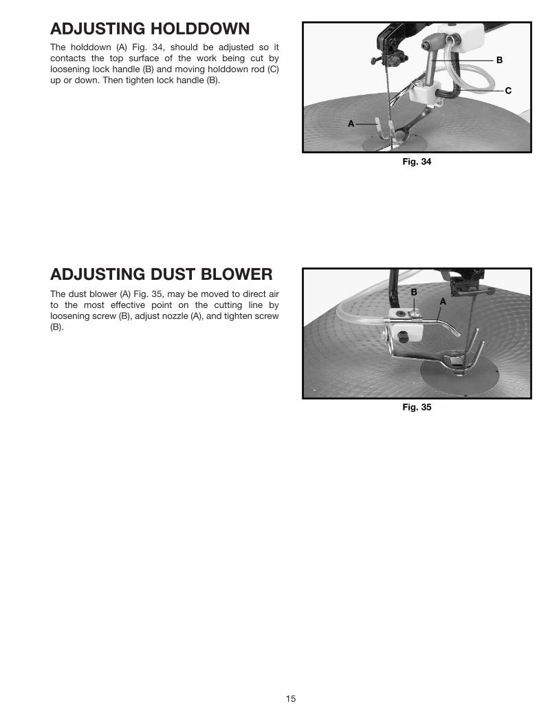
ADJUSTING HOLDDOWNThe holddown (A) Fig. 34, should be adjusted so itcontacts the top surface of the work being cut byloosening lock handle (B) and moving holddown rod (C)up or down. Then tighten lock handle (B).
ADJUSTING DUST BLOWERThe dust blower (A) Fig. 35, may be moved to direct airto the most effective point on the cutting line byloosening screw (B), adjust nozzle (A), and tighten screw(B).
Fig. 34
A
B
C
Fig. 35
BA

16
INSIDE CUTTINGInside cutting is where the blade must be threaded through a hole in the workpiece. The Delta 16" Scroll Saw has thecapability of performing this operation quickly and easily as follows:
Fig. 36
Inside cutting can be accomplished quickly with theDelta saw. In Fig. 36, the operator has just completedone of the inside cuts and must move to the next hole.
Fig. 37
Fig. 38
Loosen lock handle (A) Fig. 37, and raise the springholddown (B). Release blade tension by moving tensionlever (C) forward and loosen upper blade holder bymoving lever (D) to the rear as shown. This will releasethe blade (E). Insert the blade (E) into the next hole in thepattern, as shown.
Place blade (E) Fig. 38, back into the upper blade holderand tighten blade by moving lever (D) forward. Movetension lever (C) to the rear as shown and lower springholddown (B). You are ready to make the next inside cut.
FOLLOWING A LINEWith your scroll saw you should be able to cut a straight or curved line with ease. Most beginners will experience bladewandering; however, they eventually learn to control it as they become more familiar with the machine. Use scrapmaterial to practice cuts before starting a project. This enables you to develop your own way of cutting and you willfind out what you can and cannot do with your saw.
Always hold the work firmly against the table and do not feed the workpiece too fast while cutting. Feed the workpieceonly fast enough so that the blade will cut. Scroll saws cut faster across the grain than they do with the grain. Allowfor this tendency when cutting patterns that shift rather quickly from with-the-grain cuts to cross-grain cuts.
Make "relief" cuts before cutting long curves and never attempt to cut a curve that is too tight for the blade being used.
C
D
A
B
E
D
E
B
C

17
LUBRICATION
Fig. 39
Fig. 40
Fig. 42
1. DISCONNECT MACHINE FROM POWER SOURCE.
2. Remove four screws (A) Fig. 39, and remove sidepanel (B) from the scroll saw.
4. Lubricate the shafts of two special screws (D) Fig.41, with a few drops of light machine oil in the areaswhere they pass through the connecting link (E). NOTE:DO NOT REMOVE SPECIAL SCREWS TO LUBRICATE.
5. Remove two pivot bolts (F) Fig. 42.
6. Thoroughly clean grease from shafts (G) Fig. 42, ofboth pivot bolts (F) and lubricate shafts (G) with a fewdrops of light machine oil.
7. Reassemble two pivot bolts (F) Fig. 42, to machine.
8. Replace side panel removed in STEP 2 and reapplytension to the blade.
3. Release blade tension by pulling tension lever (C)Fig. 40, forward as shown.
BLADE BREAKAGEBlade breakage is usually caused by one or more of the following:
1. Bending the blade during installation.
2. Improper blade tension.
3. Improper blade selection for the work being cut.
4. Forcing the work into the blade too rapidly.
5. Cutting too sharp a turn for the blade being used.
6. Improper blade speed.
Delta recommends that the scroll saw be oiled aftereach 20 hours of use, as follows:
CHOICE OF BLADE AND SPEEDYour scroll saw will accept a wide variety of 5" flat end blades and can be operated at any speed from 400 to 1800cutting strokes per minute. Consider the following as a general guideline for selecting a blade and operating speed.
1. Use a finer blade for cutting thin workpieces, for hard materials, or when a smoother cut is required.2. Use a coarser blade for cutting thick workpieces, when making straight cuts or for medium to soft materials.3. Use a blade that will have 2 teeth in the workpiece at all times.4. Most blade packaging is marked with the size of the wood the blade is intended to cut and the minimum radius
which can be cut with that blade.5. Slower speeds are generally more effective than faster speeds when using thin blades and making intricate cuts.6. Always start at a slow speed and gradually increase the speed until the optimum cutting speed is obtained.
Fig. 41
AB
C
E D
F
F
G

18
NOTES

19
NOTES

Two Year Limited WarrantyDelta will repair or replace, at its expense and at its option, any Delta machine, machine part, or machine accessory whichin normal use has proven to be defective in workmanship or material, provided that the customer returns the productprepaid to a Delta factory service center or authorized service station with proof of purchase of the product within twoyears and provides Delta with reasonable opportunity to verify the alleged defect by inspection. Delta may require thatelectric motors be returned prepaid to a motor manufacturer’s authorized station for inspection and repair or replacement.Delta will not be responsible for any asserted defect which has resulted from normal wear, misuse, abuse or repair oralteration made or specifically authorized by anyone other than an authorized Delta service facility or representative. Underno circumstances will Delta be liable for incidental or consequential damages resulting from defective products. Thiswarranty is Delta’s sole warranty and sets forth the customer’s exclusive remedy, with respect to defective products; allother warranties, express or implied, whether of merchantability, fitness for purpose, or otherwise, are expresslydisclaimed by Delta.
Printed in U.S.A.
PARTS, SERVICE OR WARRANTY ASSISTANCEAll Delta Machines and accessories are manufactured to high quality standards and are serviced by a networkof Porter-Cable • Delta Factory Service Centers and Delta Authorized Service Stations. To obtain additionalinformation regarding your Delta quality product or to obtain parts, service, warranty assistance, or the locationof the nearest service outlet, please call 1-800-223-7278 (In Canada call 1-800-463-3582).
ACCESSORIESA complete line of accessories is available from your Delta Supplier, Porter-Cable • Delta Factory Service Centers,and Delta Authorized Service Stations. Please visit our Web Site www.deltamachinery.com for a catalog orfor the name of your nearest supplier.
WARNING: Since accessories other than those offered by Delta have not been tested with this product, use of such accessories could be hazardous. For safest operation, only Delta recommended accessories should be used with this product.
20