Embed Size (px)
Citation preview

For more information, visit http://apac.idec.comB-147
ø16 Switches & Pilot Lights
A6 Series
Light duty in short 22 mm body length. Flush bezel accessories can be used to change A6 series to Flush Silhouette switches.
Standard Bezel
Flush Bezel
• See website for details on approvals and standards.
Unibodyø18 18 9
Illuminated Pushbuttons Pilot Lights Selector Switches Key Selector SwitchesPushbuttons
[ Bezel size ] [ From panel front ] [ Shape ] [ Contact rating ] [ Action ]
Light
[ Operating stroke ]
18×24
218×24
Illuminated Pushbuttons Pilot Lights Selector Switches Key Selector SwitchesPushbuttons
Light
[ Bezel size ] [ From panel front ] [ Shape ] [ Contact rating ] [ Action ] [ Operating stroke ]
Flush bezel accessories provide a sleek updated look. Enables downsizing of equipment.
Unibody
ø24 24 Unibody
Degree of protection: IP40 and IP65 (IEC 60529)
Suitable for a wide variety of office and factory aplications.
Features IDEC’s original mechanism for snap-action switching.
The LED lamp contains a current-limiting resistor and a diode for protection
against reverse connection.
Download catalogs and CAD from http://apac.idec.com B-148
ø16 A6 Series Miniature Switches & Pilot Lights
APEM
Switches & Pilot Lights
Control Boxes
Emergency Stop Switches
Enabling Switches
Safety Products
Explosion Proof
Terminal Blocks
Relays & Sockets
Circuit Protectors
Power Supplies
LED Illumination
Controllers
Operator Interfaces
Sensors
AUTO-ID
Switches & Pilot Lights
Flush Silhouette
ø16
ø22
ø30
Miniature
Pilot Lights
LB
A6
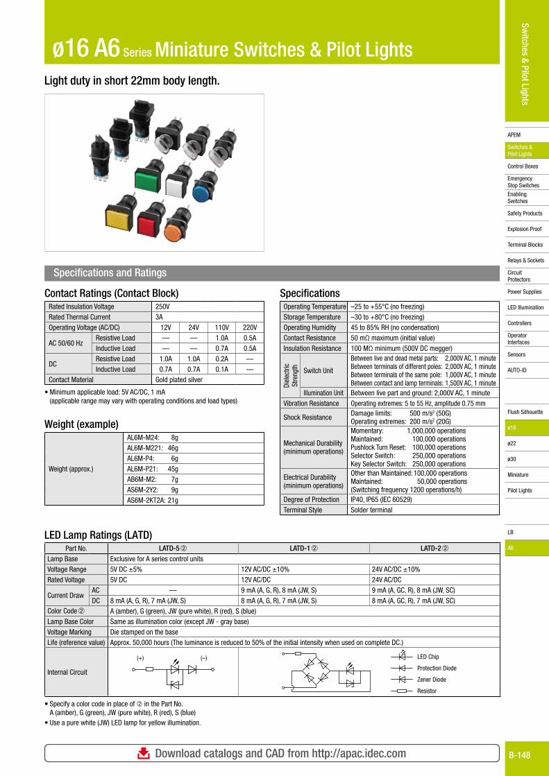
Light duty in short 22mm body length.
Contact Ratings (Contact Block)Rated Insulation Voltage 250VRated Thermal Current 3AOperating Voltage (AC/DC) 12V 24V 110V 220V
AC 50/60 HzResistive Load — — 1.0A 0.5AInductive Load — — 0.7A 0.5A
DCResistive Load 1.0A 1.0A 0.2A —Inductive Load 0.7A 0.7A 0.1A —
Contact Material Gold plated silver
• Minimum applicable load: 5V AC/DC, 1 mA (applicable range may vary with operating conditions and load types)
Weight (example)
Weight (approx.)
AL6M-M24: 8g AL6M-M221: 46gAL6M-P4: 6gAL6M-P21: 45gAB6M-M2: 7gAS6M-2Y2: 9gAS6M-2KT2A: 21g
SpecificationsOperating Temperature –25 to +55°C (no freezing)Storage Temperature –30 to +80°C (no freezing)Operating Humidity 45 to 85% RH (no condensation)Contact Resistance 50 mΩ maximum (initial value)Insulation Resistance 100 MΩ minimum (500V DC megger)
Diel
ectri
c St
reng
th Switch Unit
Between live and dead metal parts: 2,000V AC, 1 minuteBetween terminals of different poles: 2,000V AC, 1 minuteBetween terminals of the same pole: 1,000V AC, 1 minuteBetween contact and lamp terminals: 1,500V AC, 1 minute
Illumination Unit Between live part and ground: 2,000V AC, 1 minuteVibration Resistance Operating extremes: 5 to 55 Hz, amplitude 0.75 mm
Shock Resistance Damage limits: 500 m/s2 (50G)Operating extremes: 200 m/s2 (20G)
Mechanical Durability (minimum operations)
Momentary: 1,000,000 operationsMaintained: 100,000 operationsPushlock Turn Reset: 100,000 operationsSelector Switch: 250,000 operations Key Selector Switch: 250,000 operations
Electrical Durability (minimum operations)
Other than Maintained: 100,000 operationsMaintained: 50,000 operations(Switching frequency 1200 operations/h)
Degree of Protection IP40, IP65 (IEC 60529)Terminal Style Solder terminal
Specifications and Ratings
LED Lamp Ratings (LATD)Part No. LATD-5 ➁ LATD-1 ➁ LATD-2 ➁
Lamp Base Exclusive for A series control unitsVoltage Range 5V DC ±5% 12V AC/DC ±10% 24V AC/DC ±10%Rated Voltage 5V DC 12V AC/DC 24V AC/DC
Current DrawAC — 9 mA (A, G, R), 8 mA (JW, S) 9 mA (A, GC, R), 8 mA (JW, SC)DC 8 mA (A, G, R), 7 mA (JW, S) 8 mA (A, G, R), 7 mA (JW, S) 8 mA (A, GC, R), 7 mA (JW, SC)
Color Code ➁ A (amber), G (green), JW (pure white), R (red), S (blue)Lamp Base Color Same as illumination color (except JW - gray base)Voltage Marking Die stamped on the baseLife (reference value) Approx. 50,000 hours (The luminance is reduced to 50% of the initial intensity when used on complete DC.)
Internal Circuit
(+) (–) LED Chip
Resistor
Zener Diode
Protection Diode
• Specify a color code in place of ➁ in the Part No. A (amber), G (green), JW (pure white), R (red), S (blue)
• Use a pure white (JW) LED lamp for yellow illumination.
For more information, visit http://apac.idec.comB-149
APEM
Switches & Pilot Lights
Control Boxes
Emergency Stop Switches
Enabling Switches
Safety Products
Explosion Proof
Terminal Blocks
Relays & Sockets
Circuit Protectors
Power Supplies
LED Illumination
Controllers
Operator Interfaces
Sensors
AUTO-ID
Switches & Pilot Lights
Flush Silhouette
ø16
ø22
ø30
Miniature
Pilot Lights
LB
A6
ø16 A6 Series Miniature Switches & Pilot Lights
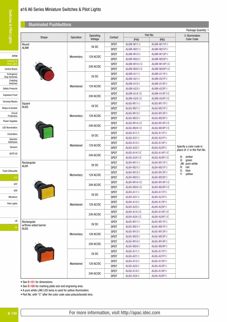
Illuminated Pushbuttons Package Quantity: 1
Shape Operation Operating Voltage Contact
Part No. ➁ Illumination Color CodeIP40 IP65
Round AL6M
Momentary
5V DC SPDT AL6M-M11➁ AL6M-M11P➁
Specify a color code in place of ➁ in the Part No.
A: amberG: greenJW: pure whiteR: redS: blueY: yellow
DPDT AL6M-M21➁ AL6M-M21P➁
12V AC/DC SPDT AL6M-M13➁ AL6M-M13P➁
DPDT AL6M-M23➁ AL6M-M23P➁
24V AC/DC SPDT AL6M-M14➁C AL6M-M14P➁C
DPDT AL6M-M24➁C AL6M-M24P➁C
Maintained
5V DC SPDT AL6M-A11➁ AL6M-A11P➁
DPDT AL6M-A21➁ AL6M-A21P➁
12V AC/DC SPDT AL6M-A13➁ AL6M-A13P➁
DPDT AL6M-A23➁ AL6M-A23P➁
24V AC/DC SPDT AL6M-A14➁C AL6M-A14P➁C
DPDT AL6M-A24➁C AL6M-A24P➁C
Square AL6Q
Momentary
5V DC SPDT AL6Q-M11➁ AL6Q-M11P➁
DPDT AL6Q-M21➁ AL6Q-M21P➁
12V AC/DC SPDT AL6Q-M13➁ AL6Q-M13P➁
DPDT AL6Q-M23➁ AL6Q-M23P➁
24V AC/DC SPDT AL6Q-M14➁C AL6Q-M14P➁C
DPDT AL6Q-M24➁C AL6Q-M24P➁C
Maintained
5V DC SPDT AL6Q-A11➁ AL6Q-A11P➁
DPDT AL6Q-A21➁ AL6Q-A21P➁
12V AC/DC SPDT AL6Q-A13➁ AL6Q-A13P➁
DPDT AL6Q-A23➁ AL6Q-A23P➁
24V AC/DC SPDT AL6Q-A14➁C AL6Q-A14P➁C
DPDT AL6Q-A24➁C AL6Q-A24P➁C
Rectangular AL6H
Momentary
5V DC SPDT AL6H-M11➁ AL6H-M11P➁
DPDT AL6H-M21➁ AL6H-M21P➁
12V AC/DC SPDT AL6H-M13➁ AL6H-M13P➁
DPDT AL6H-M23➁ AL6H-M23P➁
24V AC/DC SPDT AL6H-M14➁C AL6H-M14P➁C
DPDT AL6H-M24➁C AL6H-M24P➁C
Maintained
5V DC SPDT AL6H-A11➁ AL6H-A11P➁
DPDT AL6H-A21➁ AL6H-A21P➁
12V AC/DC SPDT AL6H-A13➁ AL6H-A13P➁
DPDT AL6H-A23➁ AL6H-A23P➁
24V AC/DC SPDT AL6H-A14➁C AL6H-A14P➁C
DPDT AL6H-A24➁C AL6H-A24P➁C
Rectangular w/three-sided barrier AL6G
Momentary
5V DC SPDT AL6G-M11➁ AL6G-M11P➁
DPDT AL6G-M21➁ AL6G-M21P➁
12V AC/DC SPDT AL6G-M13➁ AL6G-M13P➁
DPDT AL6G-M23➁ AL6G-M23P➁
24V AC/DC SPDT AL6G-M14➁ AL6G-M14P➁
DPDT AL6G-M24➁ AL6G-M24P➁
Maintained
5V DC SPDT AL6G-A11➁ AL6G-A11P➁
DPDT AL6G-A21➁ AL6G-A21P➁
12V AC/DC SPDT AL6G-A13➁ AL6G-A13P➁
DPDT AL6G-A23➁ AL6G-A23P➁
24V AC/DC SPDT AL6G-A14➁ AL6G-A14P➁
DPDT AL6G-A24➁ AL6G-A24P➁
• See B-151 for dimensions.• See B-166 for marking plate size and engraving area.• A pure white (JW) LED lamp is used for yellow illumination.• Part No. with “C” after the color code uses polycarbonate lens.
Download catalogs and CAD from http://apac.idec.com B-150
APEM
Switches & Pilot Lights
Control Boxes
Emergency Stop Switches
Enabling Switches
Safety Products
Explosion Proof
Terminal Blocks
Relays & Sockets
Circuit Protectors
Power Supplies
LED Illumination
Controllers
Operator Interfaces
Sensors
AUTO-ID
Switches & Pilot Lights
Flush Silhouette
ø16
ø22
ø30
Miniature
Pilot Lights
LB
A6
ø16 A6 Series Miniature Switches & Pilot Lights
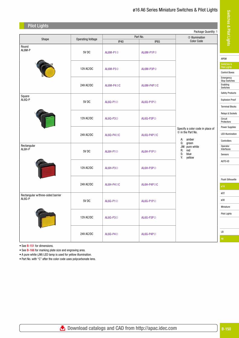
Pilot Lights Package Quantity: 1
Shape Operating VoltagePart No. ➁ Illumination
Color CodeIP40 IP65
Round AL6M-P
5V DC AL6M-P1➁ AL6M-P1P➁
Specify a color code in place of ➁ in the Part No.
A: amberG: greenJW: pure whiteR: redS: blueY: yellow
12V AC/DC AL6M-P3➁ AL6M-P3P➁
24V AC/DC AL6M-P4➁C AL6M-P4P➁C
Square AL6Q-P
5V DC AL6Q-P1➁ AL6Q-P1P➁
12V AC/DC AL6Q-P3➁ AL6Q-P3P➁
24V AC/DC AL6Q-P4➁C AL6Q-P4P➁C
Rectangular AL6H-P
5V DC AL6H-P1➁ AL6H-P1P➁
12V AC/DC AL6H-P3➁ AL6H-P3P➁
24V AC/DC AL6H-P4➁C AL6H-P4P➁C
Rectangular w/three-sided barrier AL6G-P
5V DC AL6G-P1➁ AL6G-P1P➁
12V AC/DC AL6G-P3➁ AL6G-P3P➁
24V AC/DC AL6G-P4➁ AL6G-P4P➁
• See B-151 for dimensions.• See B-166 for marking plate size and engraving area.• A pure white (JW) LED lamp is used for yellow illumination.• Part No. with “C” after the color code uses polycarbonate lens.
For more information, visit http://apac.idec.comB-151
APEM
Switches & Pilot Lights
Control Boxes
Emergency Stop Switches
Enabling Switches
Safety Products
Explosion Proof
Terminal Blocks
Relays & Sockets
Circuit Protectors
Power Supplies
LED Illumination
Controllers
Operator Interfaces
Sensors
AUTO-ID
Switches & Pilot Lights
Flush Silhouette
ø16
ø22
ø30
Miniature
Pilot Lights
LB
A6
ø16 A6 Series Miniature Switches & Pilot Lights
Mounting Hole Layout
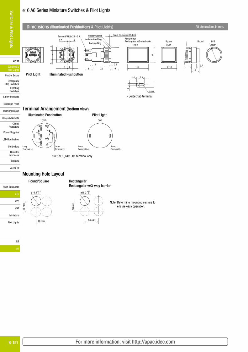
Dimensions (Illuminated Pushbuttons & Pilot Lights) All dimensions in mm.
2.6
2-R0.6
1.0
1.2
*Solder/tab terminal
Anti-rotation Ring
Rubber Gasket
Locking Ring (TOP)
RectangularRectangular w/3-way barrier Round
(TOP)Square(TOP)
Terminal Width 2.8×0.5t Panel Thickness 0.5 to 6
5.7
9�1824
18
1 0.6
8 22 9
2.5 3
55
6 6
Ø18
Pilot Light Illuminated Pushbutton
1NO: NC1, NO1, C1 terminal only
Terminal Arrangement (bottom view)Illuminated Pushbutton Pilot Light
NC1
NO1
C1
NC2
NO2
C2LampTerminal (+)
LampTerminal (–)
(TOP)
LampTerminal (+)
LampTerminal (–)
(TOP)
Round/Square Rectangular Rectangular w/3-way barrier
Note: Determine mounting centers to ensure easy operation.
ø16.2 0+0.2
18 min.
18 m
in.
ø16.2 0+0.2
24 min.
18 m
in.
Download catalogs and CAD from http://apac.idec.com B-152
APEM
Switches & Pilot Lights
Control Boxes
Emergency Stop Switches
Enabling Switches
Safety Products
Explosion Proof
Terminal Blocks
Relays & Sockets
Circuit Protectors
Power Supplies
LED Illumination
Controllers
Operator Interfaces
Sensors
AUTO-ID
Switches & Pilot Lights
Flush Silhouette
ø16
ø22
ø30
Miniature
Pilot Lights
LB
A6
ø16 A6 Series Miniature Switches & Pilot Lights
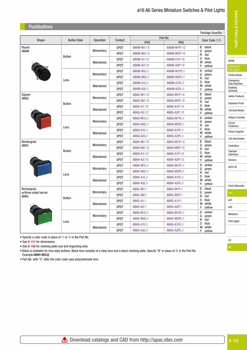
Pushbuttons Package Quantity: 1
Shape Button Style Operation ContactPart No.
Color Code ➀➁IP40 IP65
Round AB6M
Button
MomentarySPDT AB6M-M1➀C AB6M-M1P➀C B black
G: greenR: redS: blueW: whiteY: yellow
DPDT AB6M-M2➀C AB6M-M2P➀C
MaintainedSPDT AB6M-A1➀C AB6M-A1P➀C
DPDT AB6M-A2➀C AB6M-A2P➀C
Lens
MomentarySPDT AB6M-M1L➁ AB6M-M1PL➁ A: amber
G: greenR: redS: blueW: whiteY: yellow
DPDT AB6M-M2L➁ AB6M-M2PL➁
MaintainedSPDT AB6M-A1L➁ AB6M-A1PL➁
DPDT AB6M-A2L➁ AB6M-A2PL➁
Square AB6Q
Button
MomentarySPDT AB6Q-M1➀C AB6Q-M1P➀C B black
G: greenR: redS: blueW: whiteY: yellow
DPDT AB6Q-M2➀C AB6Q-M2P➀C
MaintainedSPDT AB6Q-A1➀C AB6Q-A1P➀C
DPDT AB6Q-A2➀C AB6Q-A2P➀C
Lens
MomentarySPDT AB6Q-M1L➁ AB6Q-M1PL➁ A: amber
G: greenR: redS: blueW: whiteY: yellow
DPDT AB6Q-M2L➁ AB6Q-M2PL➁
MaintainedSPDT AB6Q-A1L➁ AB6Q-A1PL➁
DPDT AB6Q-A2L➁ AB6Q-A2PL➁
Rectangular AB6H
Button
MomentarySPDT AB6H-M1➀C AB6H-M1P➀C B black
G: greenR: redS: blueW: whiteY: yellow
DPDT AB6H-M2➀C AB6H-M2P➀C
MaintainedSPDT AB6H-A1➀C AB6H-A1P➀C
DPDT AB6H-A2➀C AB6H-A2P➀C
Lens
MomentarySPDT AB6H-M1L➁ AB6H-M1PL➁ A: amber
G: greenR: redS: blueW: whiteY: yellow
DPDT AB6H-M2L➁ AB6H-M2PL➁
MaintainedSPDT AB6H-A1L➁ AB6H-A1PL➁
DPDT AB6H-A2L➁ AB6H-A2PL➁
Rectangular w/three-sided barrier AB6G Button
MomentarySPDT AB6G-M1➀ AB6G-M1P➀ B black
G: greenR: redS: blueW: whiteY: yellow
DPDT AB6G-M2➀ AB6G-M2P➀
MaintainedSPDT AB6G-A1➀ AB6G-A1P➀
DPDT AB6G-A2➀ AB6G-A2P➀
Lens
MomentarySPDT AB6G-M1L➁ AB6G-M1PL➁ A: amber
G: greenR: redS: blueW: whiteY: yellow
DPDT AB6G-M2L➁ AB6G-M2PL➁
MaintainedSPDT AB6G-A1L➁ AB6G-A1PL➁
DPDT AB6G-A2L➁ AB6G-A2PL➁
• Specify a color code in place of ➀ or ➁ in the Part No. • See B-151 for dimensions.• See B-166 for marking plate size and engraving area.• Black is available for lens style buttons. Black lens consists of a clear lens and a black marking plate. Specify “B” in place of ➁ in the Part No.
Example:AB6H-M2LB• Part No. with “C” after the color code uses polycarbonate lens.
For more information, visit http://apac.idec.comB-153
APEM
Switches & Pilot Lights
Control Boxes
Emergency Stop Switches
Enabling Switches
Safety Products
Explosion Proof
Terminal Blocks
Relays & Sockets
Circuit Protectors
Power Supplies
LED Illumination
Controllers
Operator Interfaces
Sensors
AUTO-ID
Switches & Pilot Lights
Flush Silhouette
ø16
ø22
ø30
Miniature
Pilot Lights
LB
A6
ø16 A6 Series Miniature Switches & Pilot Lights
Mounting Hole Layout
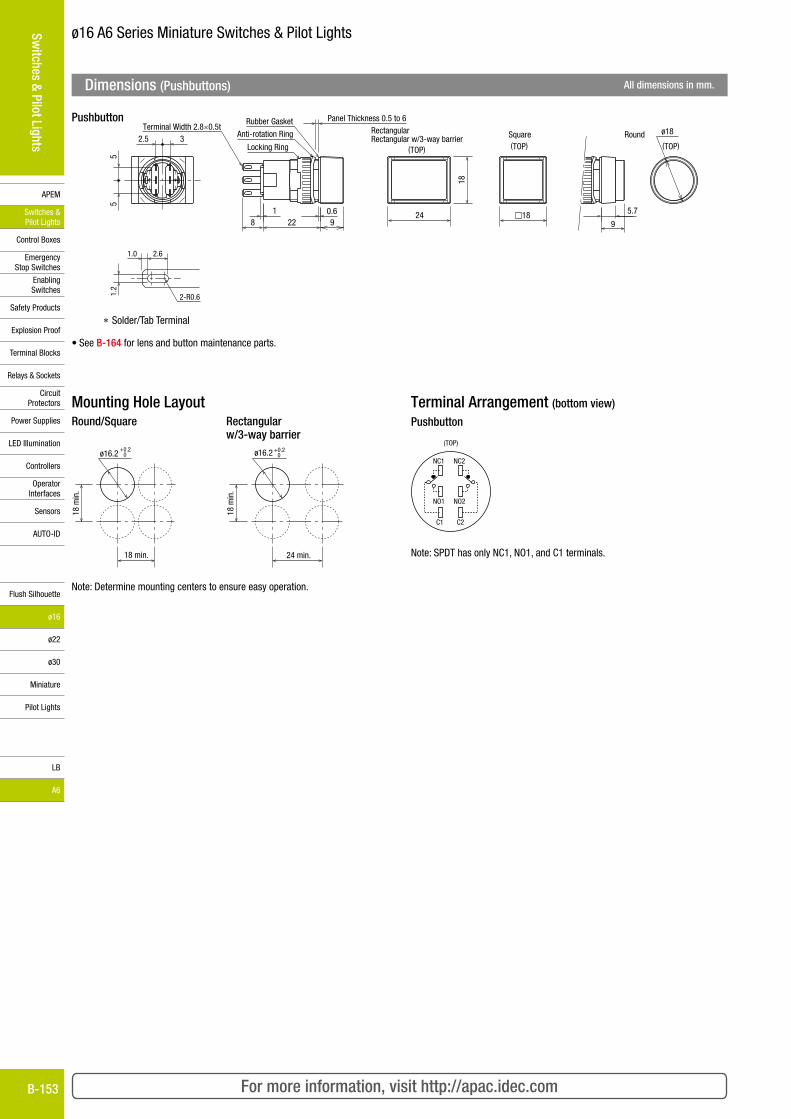
Dimensions (Pushbuttons) All dimensions in mm.
Anti-rotation Ring
Rubber Gasket
Locking Ring
ø18
(TOP)
RectangularRectangular w/3-way barrier RoundSquare
Terminal Width 2.8×0.5t
5.7
91824
18
1 0.68 22 9
Panel Thickness 0.5 to 6
2.5 3
55
(TOP)(TOP)
Pushbutton
ø16.2 0+0.2
18 min.
18 m
in.
ø16.2 0+0.2
24 min.
18 m
in.
NC1
NO1
C1
NC2
NO2
C2
(TOP)
Round/Square Rectangular w/3-way barrier
Note: Determine mounting centers to ensure easy operation.
Note: SPDT has only NC1, NO1, and C1 terminals.
Terminal Arrangement (bottom view)
Pushbutton
• See B-164 for lens and button maintenance parts.
* Solder/Tab Terminal
2.6
2-R0.6
1.0
1.2
Download catalogs and CAD from http://apac.idec.com B-154
APEM
Switches & Pilot Lights
Control Boxes
Emergency Stop Switches
Enabling Switches
Safety Products
Explosion Proof
Terminal Blocks
Relays & Sockets
Circuit Protectors
Power Supplies
LED Illumination
Controllers
Operator Interfaces
Sensors
AUTO-ID
Switches & Pilot Lights
Flush Silhouette
ø16
ø22
ø30
Miniature
Pilot Lights
LB
A6
ø16 A6 Series Miniature Switches & Pilot Lights
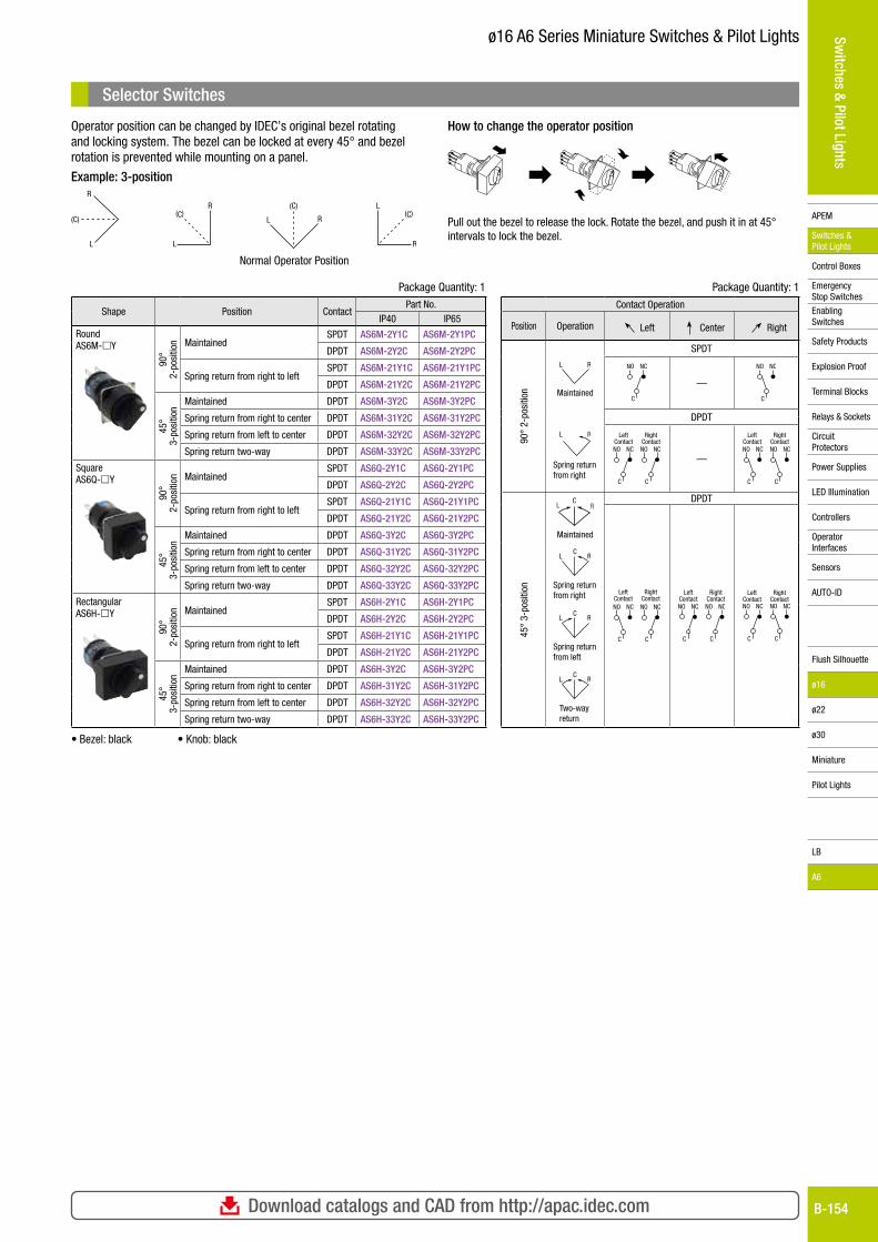
Selector Switches
Package Quantity: 1
Shape Position ContactPart No.
IP40 IP65
RoundAS6M-Y
90°
2-po
sitio
n MaintainedSPDT AS6M-2Y1C AS6M-2Y1PC
DPDT AS6M-2Y2C AS6M-2Y2PC
Spring return from right to leftSPDT AS6M-21Y1C AS6M-21Y1PC
DPDT AS6M-21Y2C AS6M-21Y2PC
45°
3-po
sitio
n
Maintained DPDT AS6M-3Y2C AS6M-3Y2PC
Spring return from right to center DPDT AS6M-31Y2C AS6M-31Y2PC
Spring return from left to center DPDT AS6M-32Y2C AS6M-32Y2PC
Spring return two-way DPDT AS6M-33Y2C AS6M-33Y2PC
SquareAS6Q-Y
90°
2-po
sitio
n MaintainedSPDT AS6Q-2Y1C AS6Q-2Y1PC
DPDT AS6Q-2Y2C AS6Q-2Y2PC
Spring return from right to leftSPDT AS6Q-21Y1C AS6Q-21Y1PC
DPDT AS6Q-21Y2C AS6Q-21Y2PC
45°
3-po
sitio
n
Maintained DPDT AS6Q-3Y2C AS6Q-3Y2PC
Spring return from right to center DPDT AS6Q-31Y2C AS6Q-31Y2PC
Spring return from left to center DPDT AS6Q-32Y2C AS6Q-32Y2PC
Spring return two-way DPDT AS6Q-33Y2C AS6Q-33Y2PC
RectangularAS6H-Y
90°
2-po
sitio
n MaintainedSPDT AS6H-2Y1C AS6H-2Y1PC
DPDT AS6H-2Y2C AS6H-2Y2PC
Spring return from right to leftSPDT AS6H-21Y1C AS6H-21Y1PC
DPDT AS6H-21Y2C AS6H-21Y2PC
45°
3-po
sitio
n
Maintained DPDT AS6H-3Y2C AS6H-3Y2PC
Spring return from right to center DPDT AS6H-31Y2C AS6H-31Y2PC
Spring return from left to center DPDT AS6H-32Y2C AS6H-32Y2PC
Spring return two-way DPDT AS6H-33Y2C AS6H-33Y2PC
• Bezel: black • Knob: black
Package Quantity: 1Contact Operation
Position Operation Left Center Right
90°
2-po
sitio
n
L R
Maintained
SPDT
NO
C
NC
—
NO
C
NC
DPDT
L RR
Spring return from right
LeftContactNO
C
NC
RightContactNO
C
NC
—NO
C
NC NO
C
NC
LeftContact
RightContact
45°
3-po
sitio
n
CRRLL
Maintained
DPDT
NO
C
NC NO
C
NC
LeftContact
RightContact
LeftContactNO
C
NC
RightContactNO
C
NC NO
C
NC NO
C
NC
LeftContact
RightContact
LC
R
Spring return from right
LC
R
Spring return from left
CL R
Two-way return
Operator position can be changed by IDEC’s original bezel rotating and locking system. The bezel can be locked at every 45° and bezel rotation is prevented while mounting on a panel.
Example: 3-positionR
L
(C)
R
L
(C)RL
(C) L
R
(C)
Normal Operator Position
How to change the operator position
Pull out the bezel to release the lock. Rotate the bezel, and push it in at 45° intervals to lock the bezel.
For more information, visit http://apac.idec.comB-155
APEM
Switches & Pilot Lights
Control Boxes
Emergency Stop Switches
Enabling Switches
Safety Products
Explosion Proof
Terminal Blocks
Relays & Sockets
Circuit Protectors
Power Supplies
LED Illumination
Controllers
Operator Interfaces
Sensors
AUTO-ID
Switches & Pilot Lights
Flush Silhouette
ø16
ø22
ø30
Miniature
Pilot Lights
LB
A6
ø16 A6 Series Miniature Switches & Pilot Lights
NC1
NO1
C1
NC2
NO2
C2
(TOP)
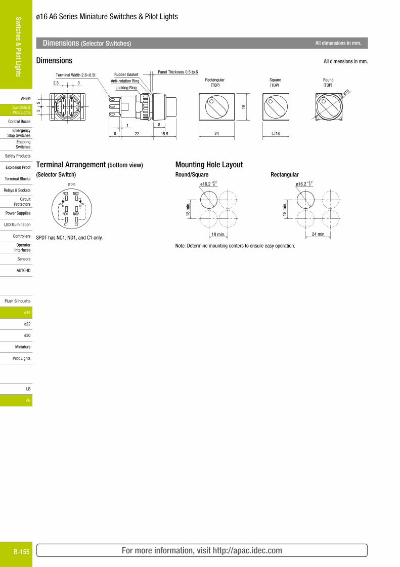
Terminal Arrangement (bottom view)(Selector Switch)
SPDT has NC1, NO1, and C1 only.
ø16.2 0+0.2
18 min.
18 m
in.
ø16.2 0+0.2
24 min.
18 m
in.
Mounting Hole LayoutRound/Square Rectangular
Note: Determine mounting centers to ensure easy operation.
Terminal Width 2.8×0.5tAnti-rotation Ring
Rubber Gasket
Locking Ring
Rectangular(TOP)
Round(TOP)
Square(TOP)2.5 3
55
Panel Thickness 0.5 to 6
1
8 22 15.5 24
18
�18
8
ø18
Dimensions All dimensions in mm.
Dimensions (Selector Switches) All dimensions in mm.

Download catalogs and CAD from http://apac.idec.com B-156
APEM
Switches & Pilot Lights
Control Boxes
Emergency Stop Switches
Enabling Switches
Safety Products
Explosion Proof
Terminal Blocks
Relays & Sockets
Circuit Protectors
Power Supplies
LED Illumination
Controllers
Operator Interfaces
Sensors
AUTO-ID
Switches & Pilot Lights
Flush Silhouette
ø16
ø22
ø30
Miniature
Pilot Lights
LB
A6
ø16 A6 Series Miniature Switches & Pilot Lights
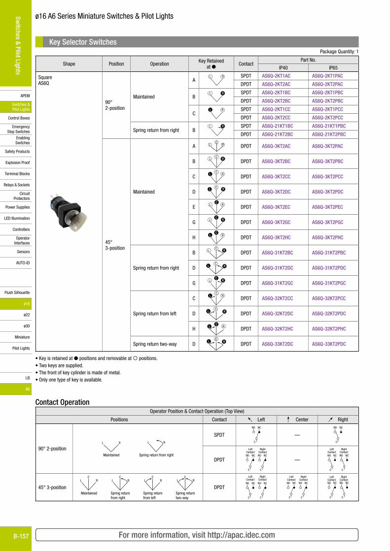
Key Selector Switches Package Quantity: 1
Shape Position Operation Key Retained at ● Contact
Part No.
IP40 IP65
Round AS6M
90° 2-position
Maintained
AL R SPDT AS6M-2KT1AC AS6M-2KT1PAC
DPDT AS6M-2KT2AC AS6M-2KT2PAC
BL RR SPDT AS6M-2KT1BC AS6M-2KT1PBC
DPDT AS6M-2KT2BC AS6M-2KT2PBC
CLL R SPDT AS6M-2KT1CC AS6M-2KT1PCC
DPDT AS6M-2KT2CC AS6M-2KT2PCC
Spring return from right BL RR SPDT AS6M-21KT1BC AS6M-21KT1PBC
DPDT AS6M-21KT2BC AS6M-21KT2PBC
45° 3-position
Maintained
A LC
R DPDT AS6M-3KT2AC AS6M-3KT2PAC
BL
CRR
DPDT AS6M-3KT2BC AS6M-3KT2PBC
CC
RLLDPDT AS6M-3KT2CC AS6M-3KT2PCC
DC
RRLLDPDT AS6M-3KT2DC AS6M-3KT2PDC
E L RCC
DPDT AS6M-3KT2EC AS6M-3KT2PEC
G LCC
RRDPDT AS6M-3KT2GC AS6M-3KT2PGC
HCC
LL RDPDT AS6M-3KT2HC AS6M-3KT2PHC
Spring return from right
BC
L RR DPDT AS6M-31KT2BC AS6M-31KT2PBC
DC
RRLL DPDT AS6M-31KT2DC AS6M-31KT2PDC
GL
CCRR
DPDT AS6M-31KT2GC AS6M-31KT2PGC
Spring return from left
CC
RLLDPDT AS6M-32KT2CC AS6M-32KT2PCC
DC
RRLLDPDT AS6M-32KT2DC AS6M-32KT2PDC
HCC
LL R DPDT AS6M-32KT2HC AS6M-32KT2PHC
Spring return two-way DC
RRLLDPDT AS6M-33KT2DC AS6M-33KT2PDC
• Key is retained at ● positions and removable at positions.• Two keys are supplied.• The front of key cylinder is made of metal.• Only one type of key is available
Contact OperationOperator Position & Contact Operation (Top View)
Positions Contact Left Center Right
90° 2-positionL R
Maintained
RL
Spring return from right
SPDT
NO
C
NC
—
NO
C
NC
DPDT
LeftContactNO
C
NC
RightContactNO
C
NC
—NO
C
NC NO
C
NC
LeftContact
RightContact
45° 3-position
RLC
Maintained
RLC
Spring returnfrom right
LC
R
Spring returnfrom left
CRL
Spring returntwo-way
DPDTNO
C
NC NO
C
NC
LeftContact
RightContact
LeftContactNO
C
NC
RightContactNO
C
NC NO
C
NC NO
C
NC
LeftContact
RightContact
For more information, visit http://apac.idec.comB-157
APEM
Switches & Pilot Lights
Control Boxes
Emergency Stop Switches
Enabling Switches
Safety Products
Explosion Proof
Terminal Blocks
Relays & Sockets
Circuit Protectors
Power Supplies
LED Illumination
Controllers
Operator Interfaces
Sensors
AUTO-ID
Switches & Pilot Lights
Flush Silhouette
ø16
ø22
ø30
Miniature
Pilot Lights
LB
A6
ø16 A6 Series Miniature Switches & Pilot Lights
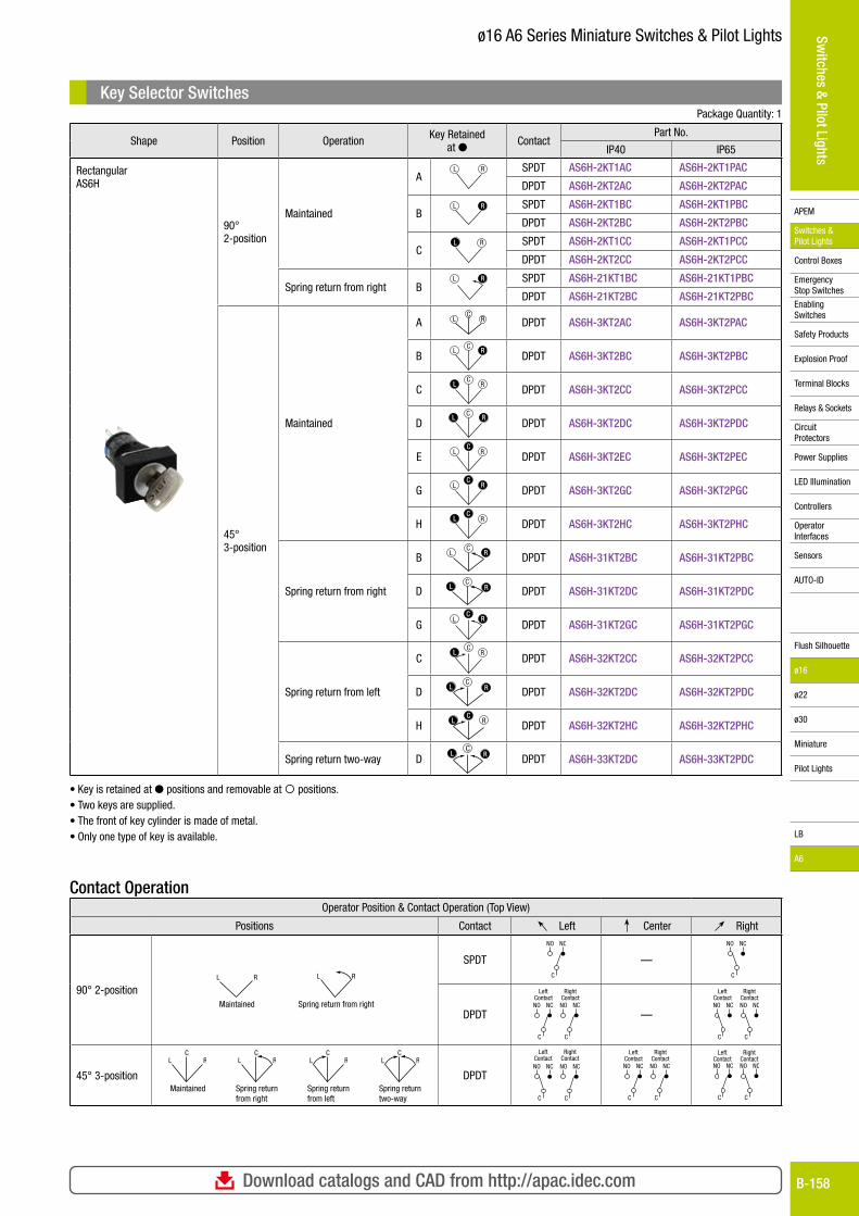
Key Selector Switches Package Quantity: 1
Shape Position Operation Key Retained at ● Contact
Part No.
IP40 IP65
Square AS6Q
90° 2-position
Maintained
AL R SPDT AS6Q-2KT1AC AS6Q-2KT1PAC
DPDT AS6Q-2KT2AC AS6Q-2KT2PAC
BL RR SPDT AS6Q-2KT1BC AS6Q-2KT1PBC
DPDT AS6Q-2KT2BC AS6Q-2KT2PBC
CLL R SPDT AS6Q-2KT1CC AS6Q-2KT1PCC
DPDT AS6Q-2KT2CC AS6Q-2KT2PCC
Spring return from right BL RR SPDT AS6Q-21KT1BC AS6Q-21KT1PBC
DPDT AS6Q-21KT2BC AS6Q-21KT2PBC
45° 3-position
Maintained
A LC
R DPDT AS6Q-3KT2AC AS6Q-3KT2PAC
BL
CRR
DPDT AS6Q-3KT2BC AS6Q-3KT2PBC
CC
RLLDPDT AS6Q-3KT2CC AS6Q-3KT2PCC
DC
RRLLDPDT AS6Q-3KT2DC AS6Q-3KT2PDC
E L RCC
DPDT AS6Q-3KT2EC AS6Q-3KT2PEC
G LCC
RRDPDT AS6Q-3KT2GC AS6Q-3KT2PGC
HCC
LL RDPDT AS6Q-3KT2HC AS6Q-3KT2PHC
Spring return from right
BC
L RR DPDT AS6Q-31KT2BC AS6Q-31KT2PBC
DC
RRLL DPDT AS6Q-31KT2DC AS6Q-31KT2PDC
GL
CCRR
DPDT AS6Q-31KT2GC AS6Q-31KT2PGC
Spring return from left
CC
RLLDPDT AS6Q-32KT2CC AS6Q-32KT2PCC
DC
RRLLDPDT AS6Q-32KT2DC AS6Q-32KT2PDC
HCC
LL R DPDT AS6Q-32KT2HC AS6Q-32KT2PHC
Spring return two-way DC
RRLLDPDT AS6Q-33KT2DC AS6Q-33KT2PDC
• Key is retained at ● positions and removable at positions.• Two keys are supplied.• The front of key cylinder is made of metal.• Only one type of key is available.
Contact OperationOperator Position & Contact Operation (Top View)
Positions Contact Left Center Right
90° 2-positionL R
Maintained
RL
Spring return from right
SPDT
NO
C
NC
—
NO
C
NC
DPDT
LeftContactNO
C
NC
RightContactNO
C
NC
—NO
C
NC NO
C
NC
LeftContact
RightContact
45° 3-position
RLC
Maintained
RLC
Spring returnfrom right
LC
R
Spring returnfrom left
CRL
Spring returntwo-way
DPDTNO
C
NC NO
C
NC
LeftContact
RightContact
LeftContactNO
C
NC
RightContactNO
C
NC NO
C
NC NO
C
NC
LeftContact
RightContact
Download catalogs and CAD from http://apac.idec.com B-158
APEM
Switches & Pilot Lights
Control Boxes
Emergency Stop Switches
Enabling Switches
Safety Products
Explosion Proof
Terminal Blocks
Relays & Sockets
Circuit Protectors
Power Supplies
LED Illumination
Controllers
Operator Interfaces
Sensors
AUTO-ID
Switches & Pilot Lights
Flush Silhouette
ø16
ø22
ø30
Miniature
Pilot Lights
LB
A6
ø16 A6 Series Miniature Switches & Pilot Lights
Key Selector Switches Package Quantity: 1
Shape Position Operation Key Retained at ● Contact
Part No.
IP40 IP65
Rectangular AS6H
90° 2-position
Maintained
AL R SPDT AS6H-2KT1AC AS6H-2KT1PAC
DPDT AS6H-2KT2AC AS6H-2KT2PAC
BL RR SPDT AS6H-2KT1BC AS6H-2KT1PBC
DPDT AS6H-2KT2BC AS6H-2KT2PBC
CLL R SPDT AS6H-2KT1CC AS6H-2KT1PCC
DPDT AS6H-2KT2CC AS6H-2KT2PCC
Spring return from right BL RR SPDT AS6H-21KT1BC AS6H-21KT1PBC
DPDT AS6H-21KT2BC AS6H-21KT2PBC
45° 3-position
Maintained
A LC
R DPDT AS6H-3KT2AC AS6H-3KT2PAC
BL
CRR
DPDT AS6H-3KT2BC AS6H-3KT2PBC
CC
RLLDPDT AS6H-3KT2CC AS6H-3KT2PCC
DC
RRLLDPDT AS6H-3KT2DC AS6H-3KT2PDC
E L RCC
DPDT AS6H-3KT2EC AS6H-3KT2PEC
G LCC
RRDPDT AS6H-3KT2GC AS6H-3KT2PGC
HCC
LL RDPDT AS6H-3KT2HC AS6H-3KT2PHC
Spring return from right
BC
L RR DPDT AS6H-31KT2BC AS6H-31KT2PBC
DC
RRLL DPDT AS6H-31KT2DC AS6H-31KT2PDC
GL
CCRR
DPDT AS6H-31KT2GC AS6H-31KT2PGC
Spring return from left
CC
RLLDPDT AS6H-32KT2CC AS6H-32KT2PCC
DC
RRLLDPDT AS6H-32KT2DC AS6H-32KT2PDC
HCC
LL R DPDT AS6H-32KT2HC AS6H-32KT2PHC
Spring return two-way DC
RRLLDPDT AS6H-33KT2DC AS6H-33KT2PDC
• Key is retained at ● positions and removable at positions.• Two keys are supplied.• The front of key cylinder is made of metal.• Only one type of key is available.
Contact OperationOperator Position & Contact Operation (Top View)
Positions Contact Left Center Right
90° 2-positionL R
Maintained
RL
Spring return from right
SPDT
NO
C
NC
—
NO
C
NC
DPDT
LeftContactNO
C
NC
RightContactNO
C
NC
—NO
C
NC NO
C
NC
LeftContact
RightContact
45° 3-position
RLC
Maintained
RLC
Spring returnfrom right
LC
R
Spring returnfrom left
CRL
Spring returntwo-way
DPDTNO
C
NC NO
C
NC
LeftContact
RightContact
LeftContactNO
C
NC
RightContactNO
C
NC NO
C
NC NO
C
NC
LeftContact
RightContact
For more information, visit http://apac.idec.comB-159
APEM
Switches & Pilot Lights
Control Boxes
Emergency Stop Switches
Enabling Switches
Safety Products
Explosion Proof
Terminal Blocks
Relays & Sockets
Circuit Protectors
Power Supplies
LED Illumination
Controllers
Operator Interfaces
Sensors
AUTO-ID
Switches & Pilot Lights
Flush Silhouette
ø16
ø22
ø30
Miniature
Pilot Lights
LB
A6
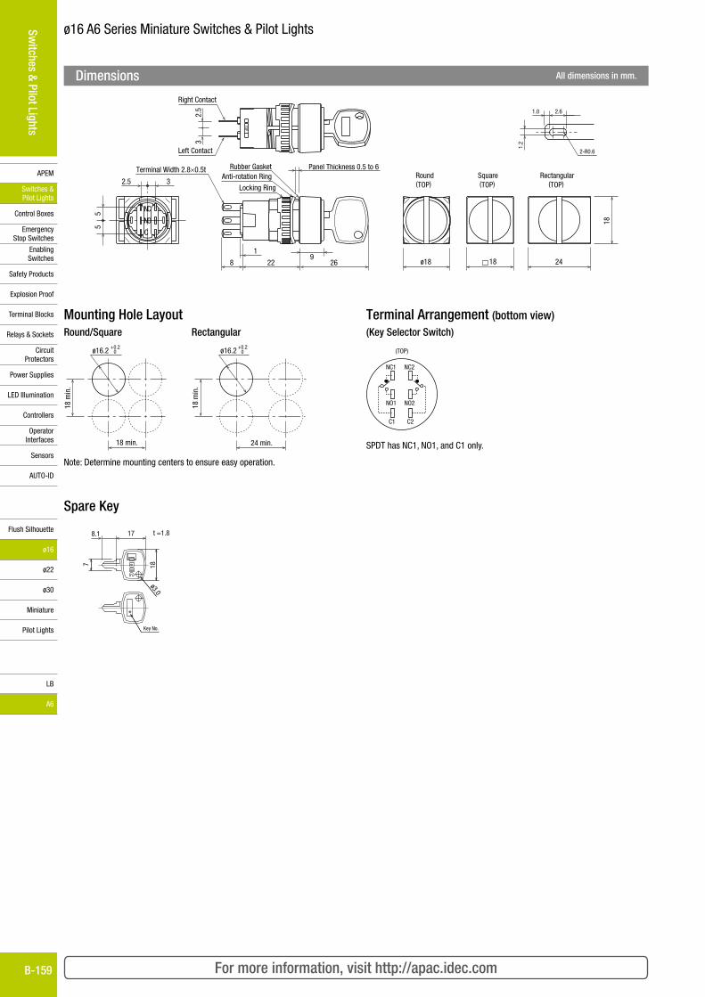
ø16 A6 Series Miniature Switches & Pilot Lights
2.6
2-R0.6
1.0
1.2
Anti-rotation RingRubber Gasket
Locking Ring
Terminal Width 2.8×0.5t
C
NC
NO
2.5 3
55
Panel Thickness 0.5 to 6
19
8 22 26
(TOP)Round Square
(TOP)Rectangular
(TOP)
2418
18
ø18
TOP
32.
5
Left Contact
Right Contact
Dimensions All dimensions in mm.
Terminal Arrangement (bottom view)(Key Selector Switch)
NC1
NO1
C1
NC2
NO2
C2
(TOP)
SPDT has NC1, NO1, and C1 only.
Mounting Hole LayoutRound/Square Rectangular
ø16.2 0+0.2
18 min.
18 m
in.
ø16.2 0+0.2
24 min.
18 m
in.
Note: Determine mounting centers to ensure easy operation.
Spare Key
7 18
ø3.0
178.1
∗
Key No.
t =1.8
Download catalogs and CAD from http://apac.idec.com B-160
APEM
Switches & Pilot Lights
Control Boxes
Emergency Stop Switches
Enabling Switches
Safety Products
Explosion Proof
Terminal Blocks
Relays & Sockets
Circuit Protectors
Power Supplies
LED Illumination
Controllers
Operator Interfaces
Sensors
AUTO-ID
Switches & Pilot Lights
Flush Silhouette
ø16
ø22
ø30
Miniature
Pilot Lights
LB
A6
ø16 A6 Series Miniature Switches & Pilot Lights
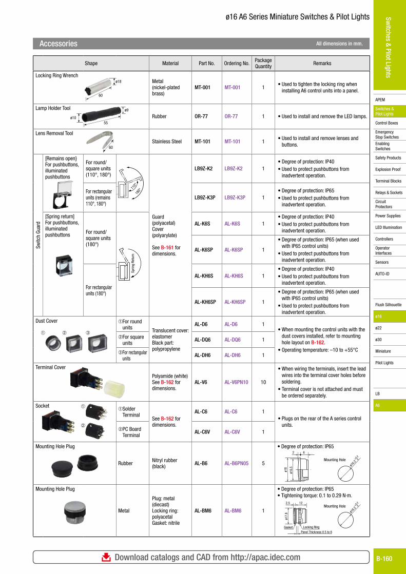
Shape Material Part No. Ordering No. Package Quantity Remarks
Locking Ring WrenchMetal (nickel-plated brass)
MT-001 MT-001 1• Used to tighten the locking ring when
installing A6 control units into a panel.
Lamp Holder Tool
Rubber OR-77 OR-77 1 • Used to install and remove the LED lamps.
Lens Removal Tool
Stainless Steel MT-101 MT-101 1• Used to install and remove lenses and
buttons.
Switc
h Gu
ard
[Remains open}For pushbuttons, illuminated pushbuttons
For round/square units (110°, 180°)
110°
180°
Guard (polyacetal)Cover (polyarylate)
See B-161 for dimen sions.
LB9Z-K2 LB9Z-K2 1• Degree of protection: IP40• Used to protect pushbuttons from
inadvertent operation.
For rectangular units (remains 110°, 180°)
LB9Z-K3P LB9Z-K3P 1 • Degree of protection: IP65• Used to protect pushbuttons from
inadvertent operation.
[Spring return]For pushbuttons, illuminated pushbuttons For round/
square units (180°)
Sprin
g Re
turn
AL-K6S AL-K6S 1• Degree of protection: IP40• Used to protect pushbuttons from
inadvertent operation.
AL-K6SP AL-K6SP 1
• Degree of protection: IP65 (when used with IP65 control units)
• Used to protect pushbuttons from inadvertent operation.
For rectangular units (180°)
AL-KH6S AL-KH6S 1• Degree of protection: IP40• Used to protect pushbuttons from
inadvertent operation.
AL-KH6SP AL-KH6SP 1
• Degree of protection: IP65 (when used with IP65 control units)
• Used to protect pushbuttons from inadvertent operation.
Dust Cover
➀ ➁ ➂
➀ For round units Translucent cover:
elastomerBlack part: polypropylene
AL-D6 AL-D6 1• When mounting the control units with the
dust covers installed, refer to mounting hole layout on B-162.
• Operating temperature: –10 to +55°C
➁ For square units
AL-DQ6 AL-DQ6 1
➂ For rectangular units
AL-DH6 AL-DH6 1
Terminal Cover
Polyamide (white) See B-162 for dimen sions.
AL-V6 AL-V6PN10 10
• When wiring the terminals, insert the lead wires into the terminal cover holes before soldering.
• Terminal cover is not attached and must be ordered separately.
Socket ➀
➁
➀ Solder Terminal
See B-162 for dimen sions.
AL-C6 AL-C6 1• Plugs on the rear of the A series control
units.➁ PC Board
TerminalAL-C6V AL-C6V 1
Mounting Hole Plug
Rubber Nitryl rubber (black) AL-B6 AL-B6PN05 5
• Degree of protection: IP652 6
ø16.
5
ø18
0+0.2
ø16.2
Mounting Hole
Mounting Hole Plug
Metal
Plug: metal (diecast)Locking ring: polyacetalGasket: nitrile
AL-BM6 AL-BM6 1
• Degree of protection: IP65• Tightening torque: 0.1 to 0.29 N·m.
0+0.2
ø16.2
Mounting Hole
Locking RingGasket
2.5 12
ø17.
8
Panel Thickness 0.5 to 6
ø18
60
ø9
55ø10
60
Accessories All dimensions in mm.
For more information, visit http://apac.idec.comB-161
APEM
Switches & Pilot Lights
Control Boxes
Emergency Stop Switches
Enabling Switches
Safety Products
Explosion Proof
Terminal Blocks
Relays & Sockets
Circuit Protectors
Power Supplies
LED Illumination
Controllers
Operator Interfaces
Sensors
AUTO-ID
Switches & Pilot Lights
Flush Silhouette
ø16
ø22
ø30
Miniature
Pilot Lights
LB
A6
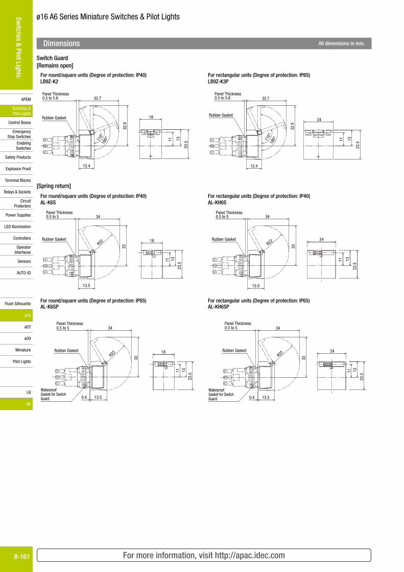
ø16 A6 Series Miniature Switches & Pilot Lights
Switch Guard[Remains open]
For round/square units (Degree of protection: IP40)LB9Z-K2
For rectangular units (Degree of protection: IP65)LB9Z-K3P
Rubber Gasket 18
23.511 1311
0°18
0°
32.9
32.7Panel Thickness0.5 to 5.6
12.4
24
11 13
23.5
32.9
32.7
12.4
Rubber Gasket
110°
180°
Panel Thickness0.5 to 5.6
[Spring return]
For round/square units (Degree of protection: IP40)AL-K6S
For rectangular units (Degree of protection: IP40)AL-KH6S
18
11 13
23.5
34
33
R22
13.5
Rubber Gasket
Panel Thickness0.5 to 5
13
23.5
11
24
34
33
R22
13.5
Rubber Gasket
Panel Thickness0.5 to 5
For round/square units (Degree of protection: IP65)AL-K6SP
For rectangular units (Degree of protection: IP65)AL-KH6SP
11
23.5
13
18
34
33
R22
13.50.4
Rubber Gasket
Panel Thickness0.5 to 5
WaterproofGasket for SwitchGuard
2411
23.5
13
34
33
R22
13.50.4
Rubber Gasket
Panel Thickness0.5 to 5
WaterproofGasket for SwitchGuard
Dimensions All dimensions in mm.
Download catalogs and CAD from http://apac.idec.com B-162
APEM
Switches & Pilot Lights
Control Boxes
Emergency Stop Switches
Enabling Switches
Safety Products
Explosion Proof
Terminal Blocks
Relays & Sockets
Circuit Protectors
Power Supplies
LED Illumination
Controllers
Operator Interfaces
Sensors
AUTO-ID
Switches & Pilot Lights
Flush Silhouette
ø16
ø22
ø30
Miniature
Pilot Lights
LB
A6
ø16 A6 Series Miniature Switches & Pilot Lights
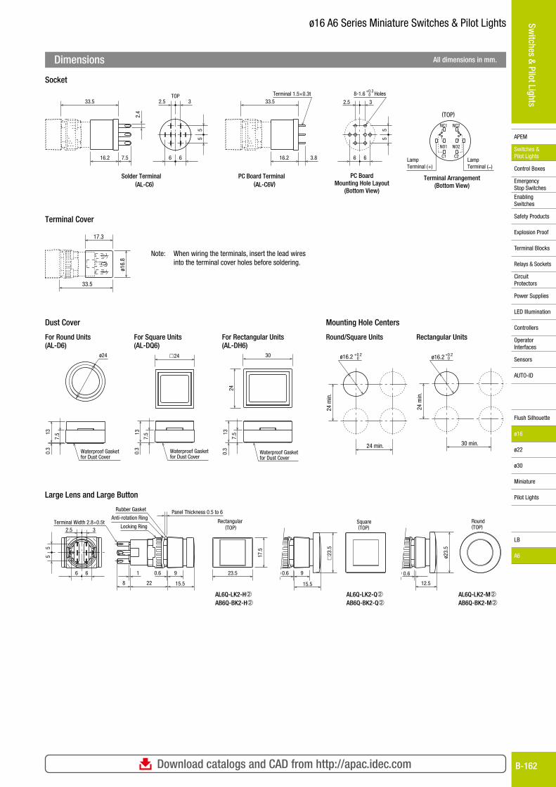
Dimensions All dimensions in mm.
Socket
Terminal Cover
Large Lens and Large Button
Dust Cover Mounting Hole Centers
PC Board Terminal(AL-C6V)
LampTerminal (+)
LampTerminal (–)
(TOP)
8-1.6 HolesTerminal 1.5×0.3t
NC1 NC2
NO1 NO2
C1 C2
0+0.3
16.2 3.8
33.5
6 6
55
32.5
Solder Terminal(AL-C6)
2.5 3
6 6
55
2.4
16.2 7.5
33.5TOP
PC BoardMounting Hole Layout
(Bottom View)
Terminal Arrangement(Bottom View)
ø16.
8
33.5
17.3
Note: When wiring the terminals, insert the lead wires into the terminal cover holes before soldering.
ø24
7.5
0.3
13
Waterproof Gasketfor Dust Cover
7.5
0.3
13
� 24
Waterproof Gasketfor Dust Cover
7.5
0.3
13
30
24
Waterproof Gasketfor Dust Cover
ø16.2 0+0.2
24 min.
24 m
in.
ø16.2 0+0.2
30 min.
24 m
in.
For Round Units (AL-D6)
For Square Units (AL-DQ6)
For Rectangular Units (AL-DH6)
Round/Square Units Rectangular Units
Anti-rotation Ring
Locking Ring
Rubber Gasket
Terminal Width 2.8×0.5t Round(TOP)
Rectangular(TOP)
Square(TOP)2.5 3
55
6 6 1 0.6 9
8 22 15.5
Panel Thickness 0.5 to 6
AL6Q-LK2-H➁AB6Q-BK2-H➁
AL6Q-LK2-Q➁AB6Q-BK2-Q➁
AL6Q-LK2-M➁AB6Q-BK2-M➁
23.5
17.5
0.6 9
15.5
� 23
.5
ø23.
5
0.6
12.5
For more information, visit http://apac.idec.comB-163
APEM
Switches & Pilot Lights
Control Boxes
Emergency Stop Switches
Enabling Switches
Safety Products
Explosion Proof
Terminal Blocks
Relays & Sockets
Circuit Protectors
Power Supplies
LED Illumination
Controllers
Operator Interfaces
Sensors
AUTO-ID
Switches & Pilot Lights
Flush Silhouette
ø16
ø22
ø30
Miniature
Pilot Lights
LB
A6
ø16 A6 Series Miniature Switches & Pilot Lights
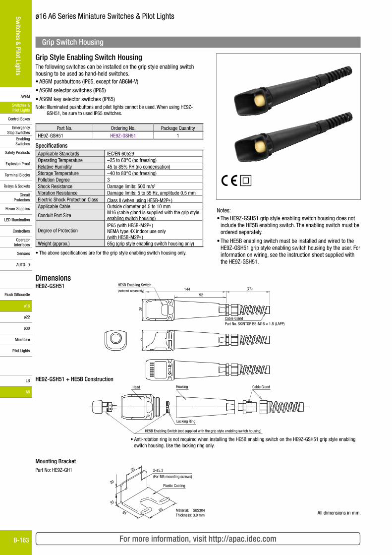
Grip Style Enabling Switch HousingThe following switches can be installed on the grip style enabling switch housing to be used as hand-held switches.• AB6M pushbuttons (IP65, except for AB6M-V)
• AS6M selector switches (IP65)
• AS6M key selector switches (IP65)Note: Illuminated pushbuttons and pilot lights cannot be used. When using HE9Z-
GSH51, be sure to used IP65 switches.
Part No. Ordering No. Package Quantity
HE9Z-GSH51 HE9Z-GSH51 1
SpecificationsApplicable Standards IEC/EN 60529Operating Temperature –25 to 60°C (no freezing)Relative Humidity 45 to 85% RH (no condensation)Storage Temperature –40 to 80°C (no freezing)Pollution Degree 3Shock Resistance Damage limits: 500 m/s2
Vibration Resistance Damage limits: 5 to 55 Hz, amplitude 0.5 mmElectric Shock Protection Class Class II (when using HE5B-M2P*)Applicable Cable Outside diameter ø4.5 to 10 mm
Conduit Port Size M16 (cable gland is supplied with the grip style enabling switch housing)
Degree of ProtectionIP65 (with HE5B-M2P*)NEMA type 4X indoor use only (with HE5B-M2P*)
Weight (approx.) 65g (grip style enabling switch housing only)
• The above specifications are for the grip style enabling switch housing only.
Notes:• The HE9Z-GSH51 grip style enabling switch housing does not
include the HE5B enabling switch. The enabling switch must be ordered separately.
• The HE5B enabling switch must be installed and wired to the HE9Z-GSH51 grip style enabling switch housing by the user. For infor mation on wiring, see the instruction sheet supplied with the HE9Z-GSH51.
Dimensions
92
(78)
38
144
Cable GlandPart No. SKINTOP BS-M16 1.5 (LAPP)
39
HE5B Enabling Switch
(ordered separately)HE9Z-GSH51
HE9Z-GSH51 + HE5B Construction
HE5B Enabling Switch (not supplied with the grip style enabling switch housing)
Locking Ring
Head Housing Cable Gland
• Anti-rotation ring is not required when installing the HE5B enabling switch on the HE9Z-GSH51 grip style enabling switch housing. Use the locking ring only.
Mounting Bracket50
20
33
81Material: SUS304Thickness: 3.0 mm
2-ø5.3
(For M5 mounting screws)
86
Plastic Coating
Part No: HE9Z-GH1
All dimensions in mm.
Grip Switch Housing
Download catalogs and CAD from http://apac.idec.com B-164
APEM
Switches & Pilot Lights
Control Boxes
Emergency Stop Switches
Enabling Switches
Safety Products
Explosion Proof
Terminal Blocks
Relays & Sockets
Circuit Protectors
Power Supplies
LED Illumination
Controllers
Operator Interfaces
Sensors
AUTO-ID
Switches & Pilot Lights
Flush Silhouette
ø16
ø22
ø30
Miniature
Pilot Lights
LB
A6
ø16 A6 Series Miniature Switches & Pilot Lights
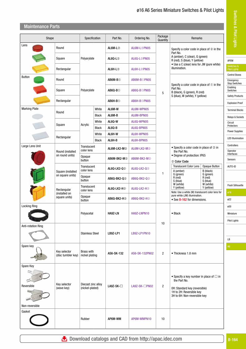
Shape Specification Part No. Ordering No. Package Quantity Remarks
LensRound
Polyarylate
AL6M-L➁ AL6M-L➁PN05
5
Specify a color code in place of ➁ in the Part No.A (amber), C (clear), G (green) R (red), S (blue), Y (yellow)• Use a C (clear) lens for JW (pure white) illumination.
Square AL6Q-L➁ AL6Q-L➁PN05
Rectangular AL6H-L➁ AL6H-L➁PN05
ButtonRound
Polyarylate
AB6M-B➀ AB6M-B➀PN05
Specify a color code in place of ➀ in the Part No.B (black), G (green), R (red) S (blue), W (white), Y (yellow)
Square AB6Q-B➀ AB6Q-B➀PN05
Rectangular AB6H-B➀ AB6H-B➀PN05
Marking PlateRound
Acrylic
White AL6M-W AL6M-WPN05
Black AL6M-B AL6M-BPN05
SquareWhite AL6Q-W AL6Q-WPN05
Black AL6Q-B AL6Q-BPN05
RectangularWhite AL6H-W AL6H-WPN05
Black AL6H-B AL6H-BPN05
Large Lens Unit
Round (installed on round units)
Translucent color lens AL6M-LK2-M➁ AL6M-LK2-M➁
1
• Specify a color code in place of ➁ in the Part No.
• Degree of protection: IP65
➁ Color CodeTranslucent Color Lens Opaque Button
A (amber) G (green) R (red) S (blue) W (white) Y (yellow)
B (black) G (green) R (red) S (blue) W (white) Y (yellow)
Note: Use a white (W) translucent color lens for pure white (JW) illumination.
• See B-162 for dimensions.
Opaque button AB6M-BK2-M➁ AB6M-BK2-M➁
Square (installed on square units)
Translucent color lens AL6Q-LK2-Q➁ AL6Q-LK2-Q➁
Opaque button AB6Q-BK2-Q➁ AB6Q-BK2-Q➁
Rectangular (installed on square units)
Translucent color lens AL6Q-LK2-H➁ AL6Q-LK2-H➁
Opaque button AB6Q-BK2-H➁ AB6Q-BK2-H➁
Locking Ring
Polyacetal HA9Z-LN HA9Z-LNPN10
10
• Black
Anti-rotation Ring
Stainless Steel LB9Z-LP1 LB9Z-LP1PN10
Spare key
Key selector (disc tumbler key)
Brass with nickel plating AS6-SK-132 AS6-SK-132PN02 2 • Thickness 1.8 mm
Spare Key
Reversible
Non-reversible
Key selector(wave key)
Diecast zinc alloy (nickel-plated) LA9Z-SK- LA9Z-SK-PN02 2
• Specify a key number in place of in the Part No.
0H: Standard key (reversible)1H to 2H: Reversible key3H to 6H: Non-reversible key
Gasket
Rubber AP6M-WM AP6M-WMPN10 10
Maintenance Parts
For more information, visit http://apac.idec.comB-165
APEM
Switches & Pilot Lights
Control Boxes
Emergency Stop Switches
Enabling Switches
Safety Products
Explosion Proof
Terminal Blocks
Relays & Sockets
Circuit Protectors
Power Supplies
LED Illumination
Controllers
Operator Interfaces
Sensors
AUTO-ID
Switches & Pilot Lights
Flush Silhouette
ø16
ø22
ø30
Miniature
Pilot Lights
LB
A6
ø16 A6 Series Miniature Switches & Pilot Lights
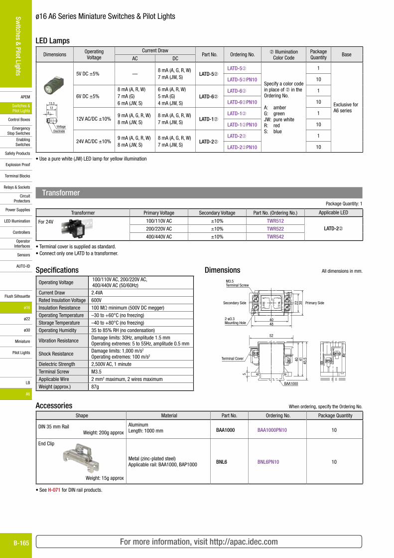
LED Lamps
Dimensions Operating Volt age
Current DrawPart No. Ordering No. ➁ Illumination
Color CodePackage Quantity Base
AC DC
Voltage Electrode
4
1213.3
5V DC ±5% —8 mA (A, G, R, W)7 mA (JW, S)
LATD-5➁LATD-5➁
Specify a color code in place of ➁ in the Ordering No.
A: amberG: greenJW: pure whiteR: redS: blue
1
Exclusive for A6 series
LATD-5➁PN10 10
6V DC ±5%8 mA (A, R, W)7 mA (G)6 mA (JW, S)
6 mA (A, R, W)5 mA (G)4 mA (JW, S)
LATD-6➁LATD-6➁ 1
LATD-6➁PN10 10
12V AC/DC ±10%9 mA (A, G, R, W)8 mA (JW, S)
8 mA (A, G, R, W)7 mA (JW, S)
LATD-1➁LATD-1➁ 1
LATD-1➁PN10 10
24V AC/DC ±10%9 mA (A, G, R, W)8 mA (JW, S)
8 mA (A, G, R, W)7 mA (JW, S)
LATD-2➁LATD-2➁ 1
LATD-2➁PN10 10
• Use a pure white (JW) LED lamp for yellow illumination
Package Quantity: 1
Transformer Primary Voltage Secondary Voltage Part No. (Ordering No.) Applicable LED
For 24V 100/110V AC ±10% TWR512LATD-2➁200/220V AC ±10% TWR522
400/440V AC ±10% TWR542
• Terminal cover is supplied as standard.• Connect only one LATD to a transformer.
SpecificationsOperating Voltage 100/110V AC, 200/220V AC,
400/440V AC (50/60Hz)Current Draw 2.4VARated Insulation Voltage 600VInsulation Resistance 100 MΩ minimum (500V DC megger)Operating Temperature –30 to +60°C (no freezing)Storage Temperature –40 to +80°C (no freezing)Operating Humidity 35 to 85% RH (no condensation)
Vibration Resistance Damage limits: 30Hz, amplitude 1.5 mmOperating extremes: 5 to 55Hz, amplitude 0.5 mm
Shock Resistance Damage limits: 1,000 m/s2
Operating extremes: 100 m/s2
Dielectric Strength 2,500V AC, 1 minuteTerminal Screw M3.5Applicable Wire 2 mm2 maximum, 2 wires maximumWeight (approx.) 87g
Dimensions All dimensions in mm.
45.5
52
4140
4840
22 30
BAA1000
134
JAPA
N 2PR
I.
SEC
.
M3.5Terminal Screw
Terminal Cover
Secondary Side Primary Side
2-ø3.3Mounting Hole
5
Accessories When ordering, specify the Ordering No.
Shape Material Part No. Ordering No. Package Quantity
DIN 35 mm RailWeight: 200g approx
AluminumLength: 1000 mm BAA1000 BAA1000PN10 10
End Clip
Weight: 15g approx
Metal (zinc-plated steel)Applicable rail: BAA1000, BAP1000 BNL6 BNL6PN10 10
• See H-071 for DIN rail products.
Transformer
Download catalogs and CAD from http://apac.idec.com B-166
APEM
Switches & Pilot Lights
Control Boxes
Emergency Stop Switches
Enabling Switches
Safety Products
Explosion Proof
Terminal Blocks
Relays & Sockets
Circuit Protectors
Power Supplies
LED Illumination
Controllers
Operator Interfaces
Sensors
AUTO-ID
Switches & Pilot Lights
Flush Silhouette
ø16
ø22
ø30
Miniature
Pilot Lights
LB
A6
ø16 A6 Series Miniature Switches & Pilot Lights
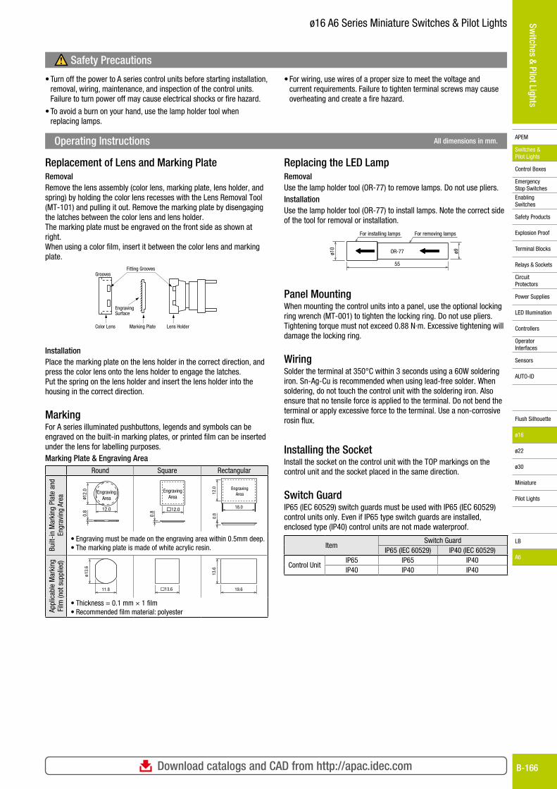
Operating Instructions All dimensions in mm.
Safety Precautions
• Turn off the power to A series control units before starting installation, removal, wiring, maintenance, and inspection of the control units. Failure to turn power off may cause electrical shocks or fire hazard.
• To avoid a burn on your hand, use the lamp holder tool when replacing lamps.
• For wiring, use wires of a proper size to meet the voltage and current requirements. Failure to tighten terminal screws may cause overheating and create a fire hazard.
Replacement of Lens and Marking PlateRemovalRemove the lens assembly (color lens, marking plate, lens holder, and spring) by holding the color lens recesses with the Lens Removal Tool (MT-101) and pulling it out. Remove the marking plate by disengaging the latches between the color lens and lens holder.The marking plate must be engraved on the front side as shown at right.When using a color film, insert it between the color lens and marking plate.
InstallationPlace the marking plate on the lens holder in the correct direction, and press the color lens onto the lens holder to engage the latches.Put the spring on the lens holder and insert the lens holder into the housing in the correct direction.
MarkingFor A series illuminated pushbuttons, legends and symbols can be engraved on the built-in marking plates, or printed film can be inserted under the lens for labelling purposes.Marking Plate & Engraving Area
Round Square Rectangular
Built
-in M
arki
ng P
late
and
En
grav
ing
Area ø 1
2.0
12.0
EngravingArea
0.8 �12.0
0.8
EngravingArea
18.0
12.0
0.8
EngravingArea
• Engraving must be made on the engraving area within 0.5mm deep.• The marking plate is made of white acrylic resin.
Appl
icab
le M
arki
ng
Film
(not
sup
plie
d)
13.6
ø
11.8 �13.6 19.6
13.6
• Thickness = 0.1 mm × 1 film• Recommended film material: polyester
Replacing the LED LampRemovalUse the lamp holder tool (OR-77) to remove lamps. Do not use pliers.InstallationUse the lamp holder tool (OR-77) to install lamps. Note the correct side of the tool for removal or installation.
ø10
ø9
55
OR-77
For removing lampsFor installing lamps
Panel MountingWhen mounting the control units into a panel, use the optional locking ring wrench (MT-001) to tighten the locking ring. Do not use pliers. Tightening torque must not exceed 0.88 N·m. Excessive tightening will damage the locking ring.
WiringSolder the terminal at 350°C within 3 seconds using a 60W soldering iron. Sn-Ag-Cu is recommended when using lead-free solder. When soldering, do not touch the control unit with the soldering iron. Also ensure that no tensile force is applied to the terminal. Do not bend the terminal or apply excessive force to the terminal. Use a non-corrosive rosin flux.
Installing the SocketInstall the socket on the control unit with the TOP markings on the control unit and the socket placed in the same direction.
Switch GuardIP65 (IEC 60529) switch guards must be used with IP65 (IEC 60529) control units only. Even if IP65 type switch guards are installed, enclosed type (IP40) control units are not made waterproof.
ItemSwitch Guard
IP65 (IEC 60529) IP40 (IEC 60529)
Control UnitIP65 IP65 IP40IP40 IP40 IP40
Fitting GroovesGrooves
EngravingSurface
Color Lens Marking Plate Lens Holder
For more information, visit http://apac.idec.comB-167
APEM
Switches & Pilot Lights
Control Boxes
Emergency Stop Switches
Enabling Switches
Safety Products
Explosion Proof
Terminal Blocks
Relays & Sockets
Circuit Protectors
Power Supplies
LED Illumination
Controllers
Operator Interfaces
Sensors
AUTO-ID
Switches & Pilot Lights
Flush Silhouette
ø16
ø22
ø30
Miniature
Pilot Lights
LB
A6
ø16 A6 Series Miniature Switches & Pilot Lights
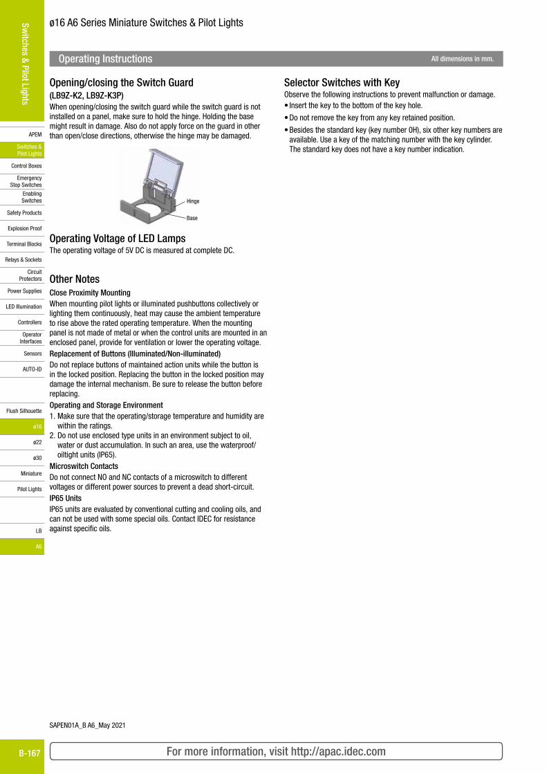
Opening/closing the Switch Guard(LB9Z-K2, LB9Z-K3P)When opening/closing the switch guard while the switch guard is not installed on a panel, make sure to hold the hinge. Holding the base might result in damage. Also do not apply force on the guard in other than open/close directions, otherwise the hinge may be damaged.
Hinge
Base
Operating Voltage of LED LampsThe operating voltage of 5V DC is measured at complete DC.
Other NotesClose Proximity MountingWhen mounting pilot lights or illuminated pushbuttons collectively or lighting them continuously, heat may cause the ambient temperature to rise above the rated operating temperature. When the mounting panel is not made of metal or when the control units are mounted in an enclosed panel, provide for ventilation or lower the operating voltage.Replacement of Buttons (Illuminated/Non-illuminated)Do not replace buttons of maintained action units while the button is in the locked position. Replacing the button in the locked position may damage the internal mechanism. Be sure to release the button before replacing.Operating and Storage Environment1. Make sure that the operating/storage temperature and humidity are
within the ratings.2. Do not use enclosed type units in an environment subject to oil,
water or dust accumulation. In such an area, use the waterproof/oiltight units (IP65).
Microswitch ContactsDo not connect NO and NC contacts of a microswitch to different voltages or different power sources to prevent a dead short-circuit.IP65 UnitsIP65 units are evaluated by conventional cutting and cooling oils, and can not be used with some special oils. Contact IDEC for resistance against specific oils.
Selector Switches with KeyObserve the following instructions to prevent malfunction or damage.• Insert the key to the bottom of the key hole.
• Do not remove the key from any key retained position.
• Besides the standard key (key number 0H), six other key numbers are available. Use a key of the matching number with the key cylinder. The standard key does not have a key number indication.
Operating Instructions All dimensions in mm.
SAPEN01A_B A6_May 2021

1. Notes on contents of Catalogs(1) Rated values, performance values, and specification values of IDEC products
listed in this Catalog are values acquired under respective conditions in independent testing, and do not guarantee values gained in combined conditions. Also, durability varies depending on the usage environment and usage conditions.
(2) Reference data and reference values listed in Catalogs are for reference purposes only, and do not guarantee that the product will always operate appropriately in that range.
(3) The specifications / appearance and accessories of IDEC products listed in Catalogs are subject to change or termination of sales without notice, for improvement or other reasons.
(4) The content of Catalogs is subject to change without notice.
2. Note on applications(1) If using IDEC products in combination with other products, confirm the
applicable laws / regulations and standards. Also, confirm that IDEC products are compatible with your systems, machines, devices, and the like by using under the actual conditions. IDEC shall bear no liability whatsoever regarding the compatibility with IDEC products.
(2) The usage examples and application examples listed in Catalogs are for reference purposes only. Therefore, when introducing a product, confirm the performance and safety of the instruments, devices, and the like before use. Furthermore, regarding these examples, IDEC does not grant license to use IDEC products to you, and IDEC offers no warranties regarding the ownership of intellectual property rights or non-infringement upon the intellectual property rights of third parties.
(3) When using IDEC products, be cautious when implementing the following.i. Use of IDEC products with sufficient allowance for rating and performanceii. Safety design, including redundant design and malfunction prevention
design that prevents other danger and damage even in the event that an IDEC product fails
iii. Wiring and installation that ensures the IDEC product used in your system, machine, device, or the like can perform and function according to its specifications
(4) Continuing to use an IDEC product even after the performance has deteriorated can result in abnormal heat, smoke, fires, and the like due to insulation deterioration or the like. Perform periodic maintenance for IDEC products and the systems, machines, devices, and the like in which they are used.
(5) IDEC products are developed and manufactured as general-purpose products for general industrial products. They are not intended for use in the following applications, and in the event that you use an IDEC product for these applications, unless otherwise agreed upon between you and IDEC, IDEC shall provide no guarantees whatsoever regarding IDEC products.i. Use in applications that require a high degree of safety, including nuclear
power control equipment, transportation equipment (railroads / airplanes / ships / vehicles / vehicle instruments, etc.), equipment for use in outer space, elevating equipment, medical instruments, safety devices, or any other equipment, instruments, or the like that could endanger life or human health
ii. Use in applications that require a high degree of reliability, such as provision systems for gas / waterworks / electricity, etc., systems that operate continuously for 24 hours, and settlement systems
iii. Use in applications where the product may be handled or used deviating from the specifications or conditions / environment listed in the Catalogs, such as equipment used outdoors or applications in environments subject to chemical pollution or electromagnetic interference If you would like to use IDEC products in the above applications, be sure to consult with an IDEC sales representative.
3. InspectionsWe ask that you implement inspections for IDEC products you purchase without delay, as well as thoroughly keep in mind management/maintenance regarding handling of the product before and during the inspection.
4. Warranty(1) Warranty period
The warranty period for IDEC products shall be one (1) year after purchase or delivery to the specified location. However, this shall not apply in cases where there is a different specification in the Catalogs or there is another agreement in place between you and IDEC.
(2) Warranty scopeShould a failure occur in an IDEC product during the above warranty period for reasons attributable to IDEC, then IDEC shall replace or repair that product, free of charge, at the purchase location / delivery location of the product, or an IDEC service base. However, failures caused by the following reasons shall be deemed outside the scope of this warranty.i. The product was handled or used deviating from the conditions / environment listed in the Catalogsii. The failure was caused by reasons other than an IDEC productiii. Modification or repair was performed by a party other than IDECiv. The failure was caused by a software program of a party other than IDECv. The product was used outside of its original purposevi. Replacement of maintenance parts, installation of accessories, or the like
was not performed properly in accordance with the user’s manual and Catalogs
vii. The failure could not have been predicted with the scientific and technical standards at the time when the product was shipped from IDECviii. The failure was due to other causes not attributable to IDEC (including
cases of force majeure such as natural disasters and other disasters)Furthermore, the warranty described here refers to a warranty on the IDEC product as a unit, and damages induced by the failure of an IDEC product are excluded from this warranty.
5. Limitation of liabilityThe warranty listed in this Agreement is the full and complete warranty for IDEC products, and IDEC shall bear no liability whatsoever regarding special damages, indirect damages, incidental damages, or passive damages that occurred due to an IDEC product.
6. Service scopeThe prices of IDEC products do not include the cost of services, such as dispatching technicians. Therefore, separate fees are required in the following cases.
(1) Instructions for installation / adjustment and accompaniment at test operation (including creating application software and testing operation, etc.)
(2) Maintenance inspections, adjustments, and repairs(3) Technical instructions and technical training(4) Product tests or inspections specified by you
The above content assumes transactions and usage within your region. Please consult with an IDEC sales representative regarding transactions and usage outside of your region. Also, IDEC provides no guarantees whatsoever regarding IDEC products sold outside your region.
Ordering Terms and ConditionsThank you for using IDEC Products.By purchasing products listed in our catalogs, datasheets, and the like (hereinafter referred to as “Catalogs”) you agree to be bound by these terms and conditions. Please read and agree to the terms and conditions before placing your order.
www.idec.comUSA IDEC Corporation Tel: +1-408-747-0550 [email protected] APEM GmbH Tel: +49-40-25 30 54-0 [email protected] IDEC Izumi Asia Pte. Ltd. Tel: +65-6746-1155 [email protected] IDEC Asia (Thailand) Co., Ltd Tel: +66-2-392-9765 [email protected] IDEC Controls India Private Limited Tel: +91-80679-35328 [email protected] IDEC Taiwan Corporation Tel: +886-2-2577-6938 [email protected]
Hong Kong IDEC Izumi (H.K.) Co., Ltd. Tel: +852-2803-8989 [email protected] IDEC (Shanghai) Corporation Tel: +86-21-6135-1515 [email protected] Beijing Branch Tel: +86-10-6581-6131 [email protected] Guangzhou Branch Tel: +86-20-8362-2394 [email protected] IDEC Corporation Tel: +81-6-6398-2527 [email protected]
Head Office6-64, Nishi-Miyahara-2-Chome, Yodogawa-ku, Osaka 532-0004, Japan
Speci�cations and other descriptions in this brochure are subject to change without notice.