Embed Size (px)
Citation preview
ECE 567 Spring 2003 University of Illinois at Chicago
Amanjyot Johar Page 1 5/9/2003
16 bit Reduced Instruction Set Computer (RISC) Processor Design A Project Report
Amanjyot Singh Johar Department of Electrical and Computer Engineering
University of Illinois at Chicago [email protected]
ECE 567 Spring 2003 University of Illinois at Chicago
Amanjyot Johar Page 2 5/9/2003
Abstract This project presents the structural design and the functional characteristics of a general purpose RISC processor. The design of the RISC processor is based on the study and evaluation of a variety of assembly instruction sets. The designed RISC processor is a pipeline RISC processor with 5 stages of pipelining. A variety of instructions have been implemented for the proposed design and care has been taken to provide a control mechanism for data, structural and timing hazards. The processor’s architecture features 16 bit instruction words, 8 internal general-purpose registers each of which can hold a 16 bit data word, and 16 external address lines to external memory. The entire processor was modeled as a bottom up approach in the design methodology. The design has been done in VHDL and synthesized using hardware tool VHDL-Simili 2.1 available from Symphony EDA. The features of this processor include 16-bit architecture and multi-cycle implementation of the data path. A number of MIPS instruction set have been implemented. The design has been done at the behavioral and structural levels of VHDL. The individual components were designed, analyzed, synthesized and tested at each level of implementation. The individual components were finally integrated in a top-level simulation by appropriate port mapping. Introduction In the mid-1970's advances in semiconductor technology began to reduce the difference in speed between main memory and processor chips. As memory speed increased, and high-level languages displaced assembly language, the major reasons for CISC began to disappear, and computer designers began to look at ways computer performance could be optimized beyond just making faster hardware. One of their key realizations was that a sequence of simple instructions produces the same results as a sequence of complex instructions, but can be implemented with a simpler (and faster) hardware design. The advances in memory design to achieve the desired speed up have been critical in the development of RISC architectures. The basic characteristics of RISC processors are:
• Simple instruction set. In a RISC machine, the instruction set contains simple, basic instructions, from which more complex instructions can be composed.
• Same length instructions. Each instruction is the same length, so that it may be fetched in a single operation.
• 1 machine-cycle instructions. Most instructions complete in one machine cycle, which allows the processor to handle several instructions at the same time. This pipelining is a key technique used to speed up RISC machines.
RISC designers are concerned primarily with creating the fastest chip possible, and so they use a number of techniques, including pipelining. Pipelining is a design technique where the computer's hardware processes more than one instruction at a time, and doesn't wait for one instruction to complete before starting the next.
ECE 567 Spring 2003 University of Illinois at Chicago
Amanjyot Johar Page 3 5/9/2003
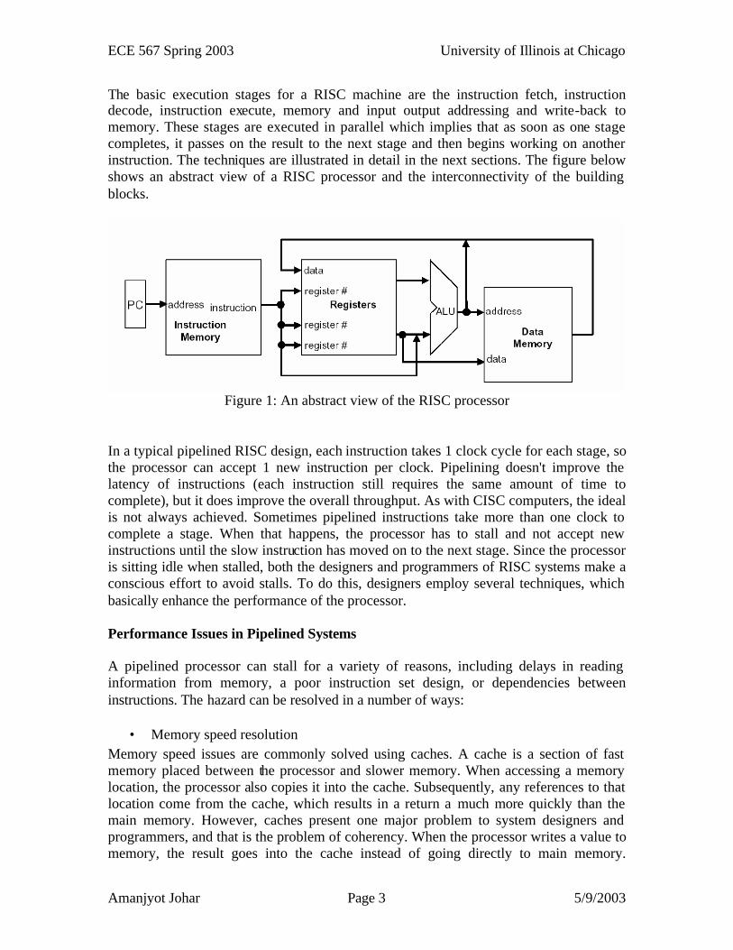
The basic execution stages for a RISC machine are the instruction fetch, instruction decode, instruction execute, memory and input output addressing and write-back to memory. These stages are executed in parallel which implies that as soon as one stage completes, it passes on the result to the next stage and then begins working on another instruction. The techniques are illustrated in detail in the next sections. The figure below shows an abstract view of a RISC processor and the interconnectivity of the building blocks.
Figure 1: An abstract view of the RISC processor
In a typical pipelined RISC design, each instruction takes 1 clock cycle for each stage, so the processor can accept 1 new instruction per clock. Pipelining doesn't improve the latency of instructions (each instruction still requires the same amount of time to complete), but it does improve the overall throughput. As with CISC computers, the ideal is not always achieved. Sometimes pipelined instructions take more than one clock to complete a stage. When that happens, the processor has to stall and not accept new instructions until the slow instruction has moved on to the next stage. Since the processor is sitting idle when stalled, both the designers and programmers of RISC systems make a conscious effort to avoid stalls. To do this, designers employ several techniques, which basically enhance the performance of the processor.
Performance Issues in Pipelined Systems
A pipelined processor can stall for a variety of reasons, including delays in reading information from memory, a poor instruction set design, or dependencies between instructions. The hazard can be resolved in a number of ways:
• Memory speed resolution Memory speed issues are commonly solved using caches. A cache is a section of fast memory placed between the processor and slower memory. When accessing a memory location, the processor also copies it into the cache. Subsequently, any references to that location come from the cache, which results in a return a much more quickly than the main memory. However, caches present one major problem to system designers and programmers, and that is the problem of coherency. When the processor writes a value to memory, the result goes into the cache instead of going directly to main memory.
ECE 567 Spring 2003 University of Illinois at Chicago
Amanjyot Johar Page 4 5/9/2003
Therefore, special hardware (usually implemented as part of the processor) needs to write the information out to main memory before something else tries to read that location or before re-using that part of the cache for some different information.
• Instruction Latency A poorly designed instruction set can cause a pipelined processor to stall frequently. Some of the more common problem areas are:
1. Highly encoded instructions such as those used on CISC machines, that require a dedicated setup to decode
2. Variable-length instructions which require multiple references to memory to fetch in the entire instruction.
3. Instructions which access main memory instead of the registers, since the main memory can be slow
4. Complex instructions which require multiple clocks for execution for example: many floating-point operations.
5. Instructions which need to read and write the same register. For example "ADD 5 to register 3" had to read register 3, add 5 to that value, then write 5 back to the same register. In such a situation, the processor may still be "busy" from the earlier read operation, causing the processor to stall until the register becomes available to write.
6. Dependence on single-point resources. For example: a condition code register. If one instruction sets the conditions in the condition code register and the following instruction tries to read those bits, the second instruction may have to stall until the first instruction's write completes.
• Dependencies One problem that RISC programmers face is that the processor can be slowed down by a poor choice of instructions. Since each instruction takes some amount of time to store its result, and several instructions are being handled at the same time, later instructions may have to wait for the results of earlier instructions to be stored. However, a simple rearrangement of the instructions in a program called Instruction Scheduling can remove these performance limitations from RISC programs. Implementation Details Design Rules and Assumptions
1. Design is to be generated for a true 16 bit processor. That is both the data-path and the instruction word are 16 bits long.
2. Processor design is based on the von-Neumann architecture of a single memory rather than separate memories for data and instructions
ECE 567 Spring 2003 University of Illinois at Chicago
Amanjyot Johar Page 5 5/9/2003
Design of the Instruction Set
The instruction set has been designed with respect to the following four instruction types. Different formats for certain instructions have been specified. This is because different instructions use different operands and hence different formats needed to be constructed for them.
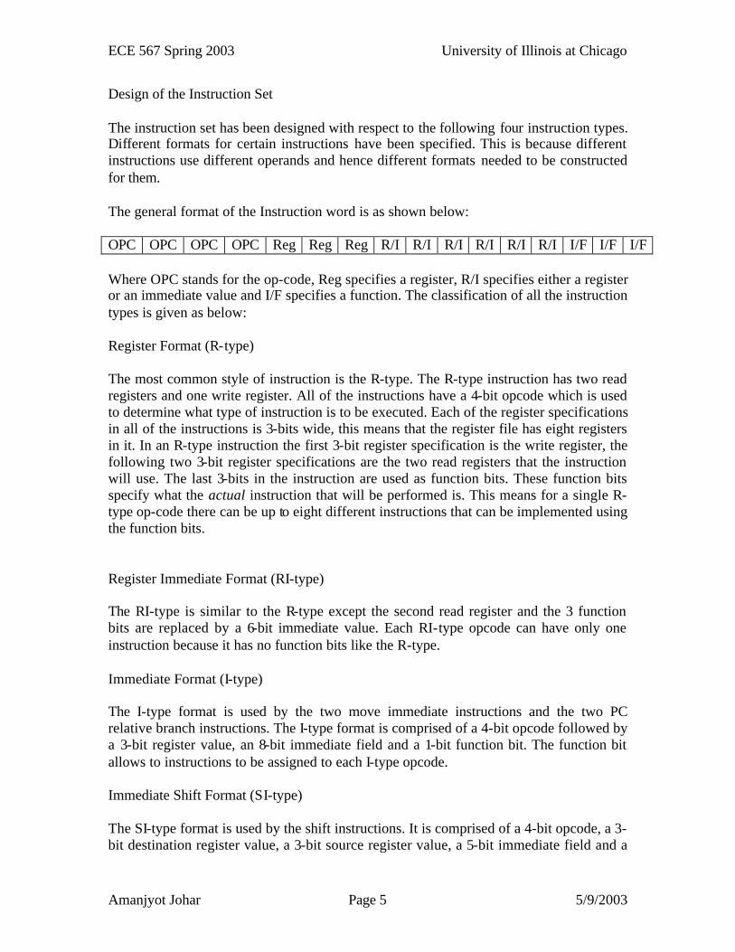
The general format of the Instruction word is as shown below:
OPC OPC OPC OPC Reg Reg Reg R/I R/I R/I R/I R/I R/I I/F I/F I/F
Where OPC stands for the op-code, Reg specifies a register, R/I specifies either a register or an immediate value and I/F specifies a function. The classification of all the instruction types is given as below:
Register Format (R-type)
The most common style of instruction is the R-type. The R-type instruction has two read registers and one write register. All of the instructions have a 4-bit opcode which is used to determine what type of instruction is to be executed. Each of the register specifications in all of the instructions is 3-bits wide, this means that the register file has eight registers in it. In an R-type instruction the first 3-bit register specification is the write register, the following two 3-bit register specifications are the two read registers that the instruction will use. The last 3-bits in the instruction are used as function bits. These function bits specify what the actual instruction that will be performed is. This means for a single R-type op-code there can be up to eight different instructions that can be implemented using the function bits.
Register Immediate Format (RI-type)
The RI-type is similar to the R-type except the second read register and the 3 function bits are replaced by a 6-bit immediate value. Each RI-type opcode can have only one instruction because it has no function bits like the R-type.
Immediate Format (I-type)
The I-type format is used by the two move immediate instructions and the two PC relative branch instructions. The I-type format is comprised of a 4-bit opcode followed by a 3-bit register value, an 8-bit immediate field and a 1-bit function bit. The function bit allows to instructions to be assigned to each I-type opcode.
Immediate Shift Format (SI-type)
The SI-type format is used by the shift instructions. It is comprised of a 4-bit opcode, a 3-bit destination register value, a 3-bit source register value, a 5-bit immediate field and a
ECE 567 Spring 2003 University of Illinois at Chicago
Amanjyot Johar Page 6 5/9/2003
1-bit function bit. The 5-bit immediate field is used to shift the source register from -15 to 16 places in the desired direction.
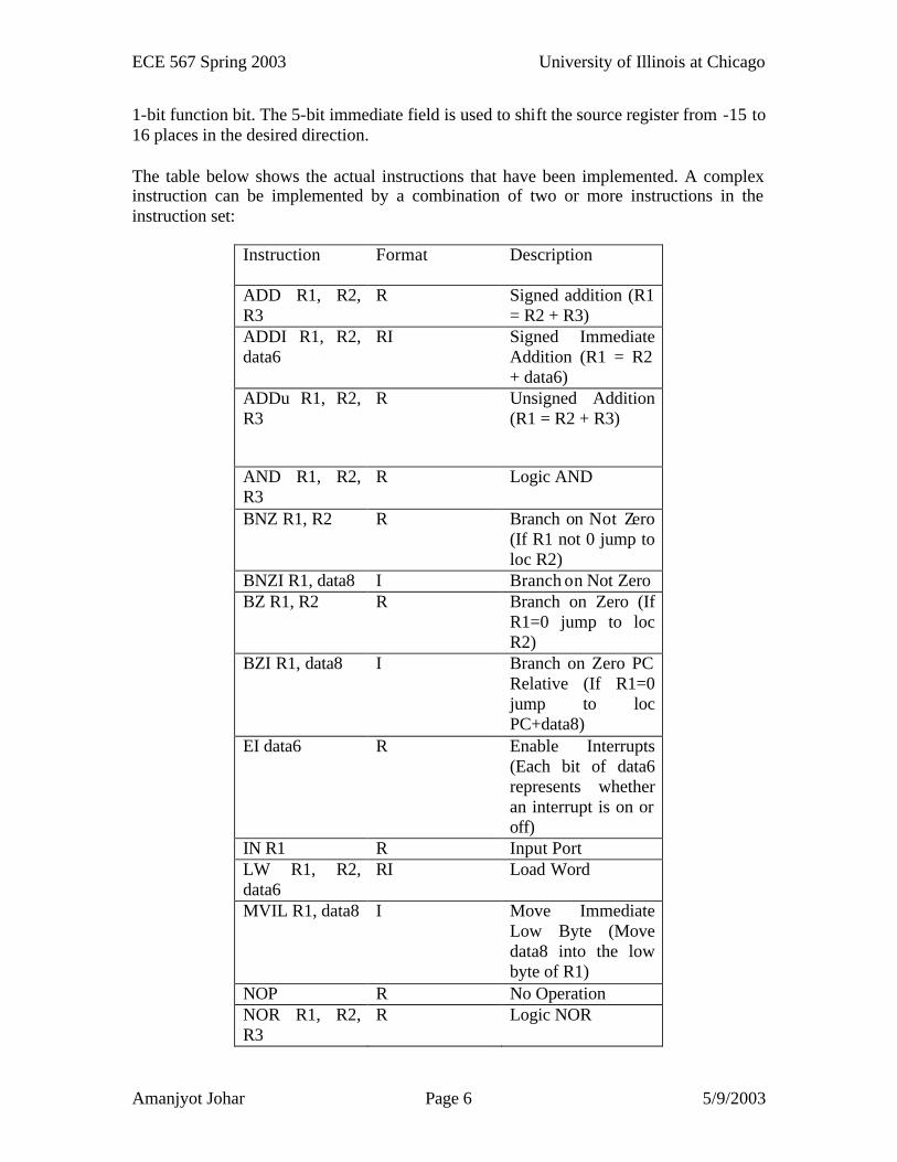
The table below shows the actual instructions that have been implemented. A complex instruction can be implemented by a combination of two or more instructions in the instruction set:
Instruction Format Description
ADD R1, R2, R3
R Signed addition (R1 = R2 + R3)
ADDI R1, R2, data6
RI Signed Immediate Addition (R1 = R2 + data6)
ADDu R1, R2, R3
R Unsigned Addition (R1 = R2 + R3)
AND R1, R2, R3
R Logic AND
BNZ R1, R2 R Branch on Not Zero (If R1 not 0 jump to loc R2)
BNZI R1, data8 I Branch on Not Zero BZ R1, R2 R Branch on Zero (If
R1=0 jump to loc R2)
BZI R1, data8 I Branch on Zero PC Relative (If R1=0 jump to loc PC+data8)
EI data6 R Enable Interrupts (Each bit of data6 represents whether an interrupt is on or off)
IN R1 R Input Port LW R1, R2, data6
RI Load Word
MVIL R1, data8 I Move Immediate Low Byte (Move data8 into the low byte of R1)
NOP R No Operation NOR R1, R2, R3
R Logic NOR
ECE 567 Spring 2003 University of Illinois at Chicago
Amanjyot Johar Page 7 5/9/2003
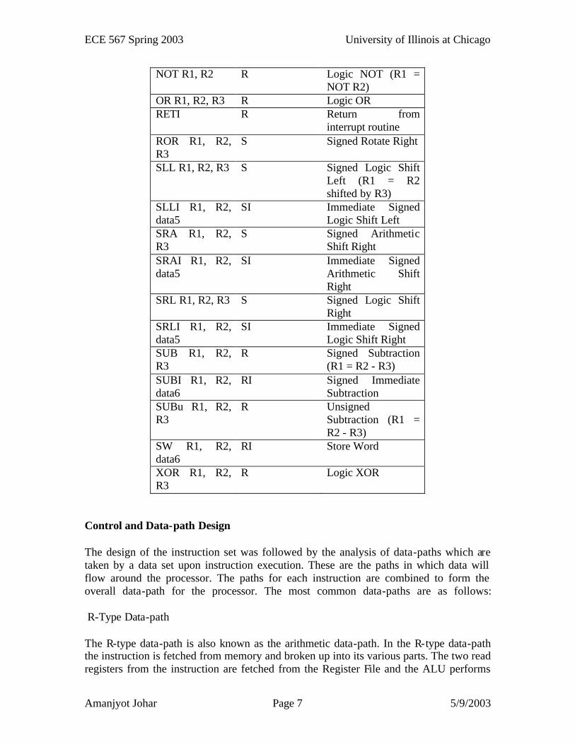
NOT R1, R2 R Logic NOT (R1 = NOT R2)
OR R1, R2, R3 R Logic OR RETI R Return from
interrupt routine ROR R1, R2, R3
S Signed Rotate Right
SLL R1, R2, R3 S Signed Logic Shift Left (R1 = R2 shifted by R3)
SLLI R1, R2, data5
SI Immediate Signed Logic Shift Left
SRA R1, R2, R3
S Signed Arithmetic Shift Right
SRAI R1, R2, data5
SI Immediate Signed Arithmetic Shift Right
SRL R1, R2, R3 S Signed Logic Shift Right
SRLI R1, R2, data5
SI Immediate Signed Logic Shift Right
SUB R1, R2, R3
R Signed Subtraction (R1 = R2 - R3)
SUBI R1, R2, data6
RI Signed Immediate Subtraction
SUBu R1, R2, R3
R Unsigned Subtraction (R1 = R2 - R3)
SW R1, R2, data6
RI Store Word
XOR R1, R2, R3
R Logic XOR
Control and Data-path Design
The design of the instruction set was followed by the analysis of data-paths which are taken by a data set upon instruction execution. These are the paths in which data will flow around the processor. The paths for each instruction are combined to form the overall data-path for the processor. The most common data-paths are as follows: R-Type Data-path
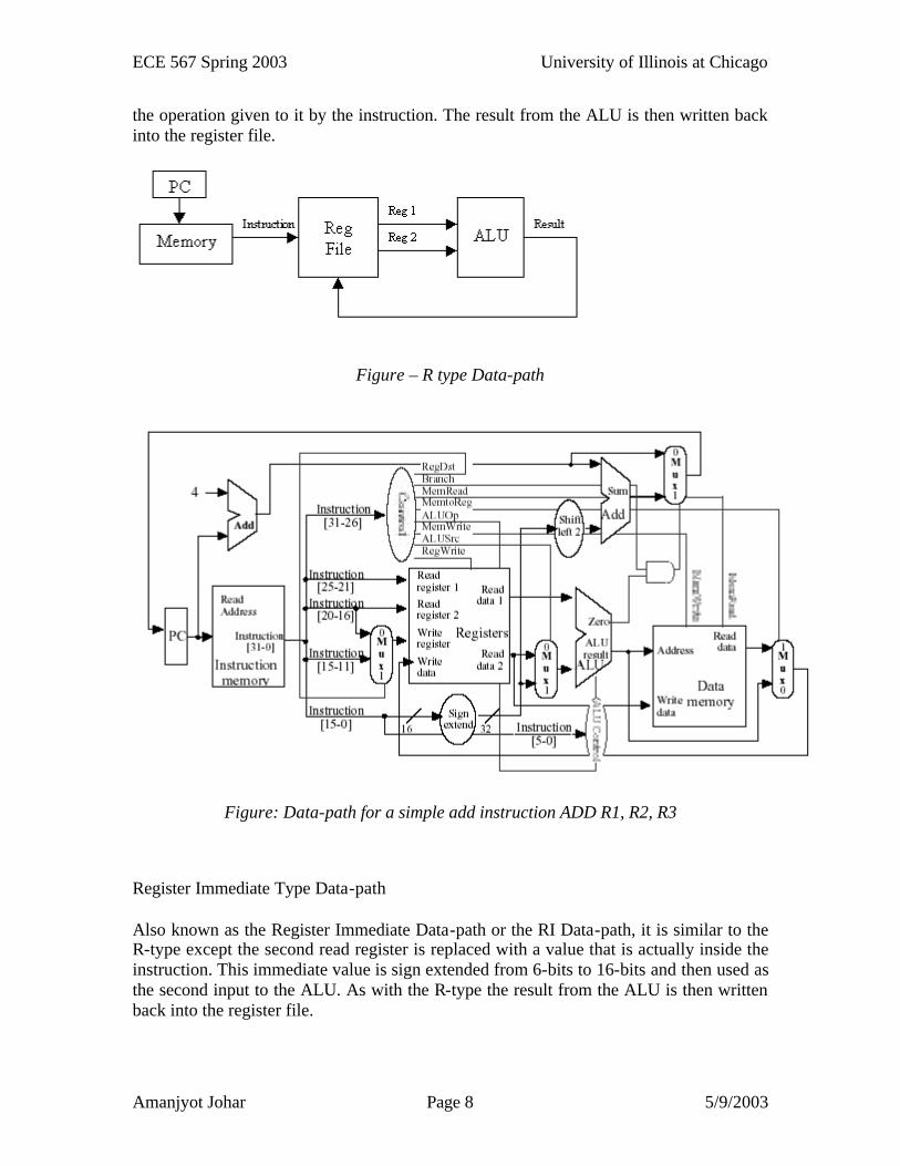
The R-type data-path is also known as the arithmetic data-path. In the R-type data-path the instruction is fetched from memory and broken up into its various parts. The two read registers from the instruction are fetched from the Register File and the ALU performs
ECE 567 Spring 2003 University of Illinois at Chicago
Amanjyot Johar Page 8 5/9/2003
the operation given to it by the instruction. The result from the ALU is then written back into the register file.
Figure – R type Data-path
Figure: Data-path for a simple add instruction ADD R1, R2, R3
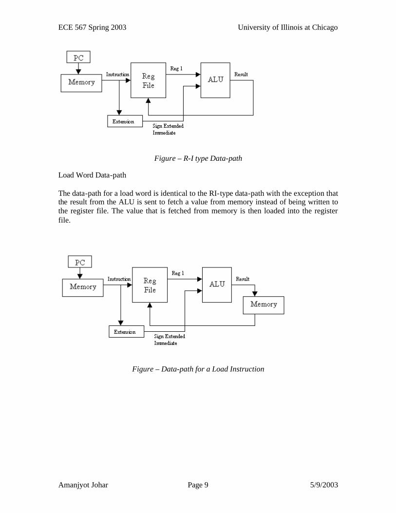
Register Immediate Type Data-path
Also known as the Register Immediate Data-path or the RI Data-path, it is similar to the R-type except the second read register is replaced with a value that is actually inside the instruction. This immediate value is sign extended from 6-bits to 16-bits and then used as the second input to the ALU. As with the R-type the result from the ALU is then written back into the register file.
ECE 567 Spring 2003 University of Illinois at Chicago
Amanjyot Johar Page 9 5/9/2003
Figure – R-I type Data-path
Load Word Data-path
The data-path for a load word is identical to the RI-type data-path with the exception that the result from the ALU is sent to fetch a value from memory instead of being written to the register file. The value that is fetched from memory is then loaded into the register file.
Figure – Data-path for a Load Instruction
ECE 567 Spring 2003 University of Illinois at Chicago
Amanjyot Johar Page 10 5/9/2003
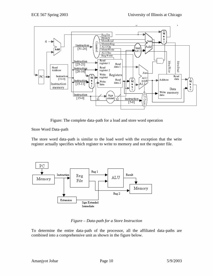
Figure: The complete data-path for a load and store word operation
Store Word Data-path
The store word data-path is similar to the load word with the exception that the write register actually specifies which register to write to memory and not the register file.
Figure – Data-path for a Store Instruction
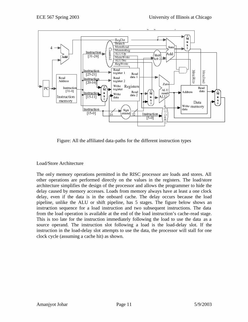
To determine the entire data-path of the processor, all the affiliated data-paths are combined into a comprehensive unit as shown in the figure below.
ECE 567 Spring 2003 University of Illinois at Chicago
Amanjyot Johar Page 11 5/9/2003
Figure: All the affiliated data-paths for the different instruction types
Load/Store Architecture
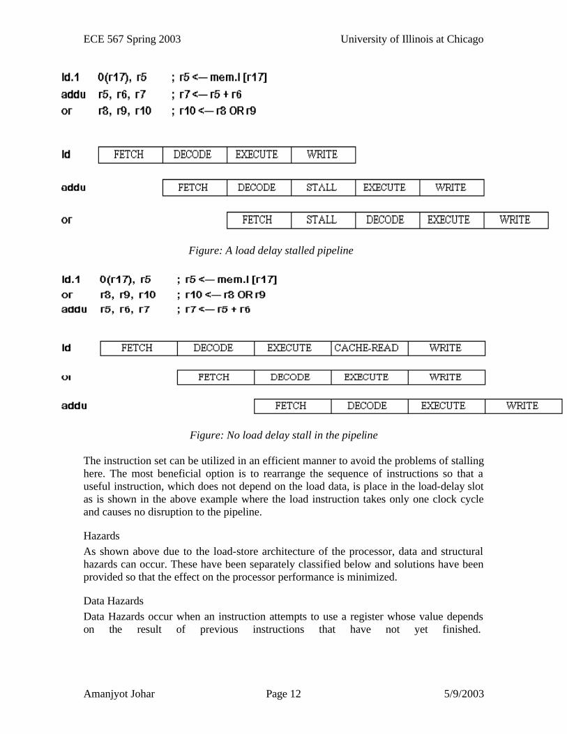
The only memory operations permitted in the RISC processor are loads and stores. All other operations are performed directly on the values in the registers. The load/store architecture simplifies the design of the processor and allows the programmer to hide the delay caused by memory accesses. Loads from memory always have at least a one clock delay, even if the data is in the onboard cache. The delay occurs because the load pipeline, unlike the ALU or shift pipeline, has 5 stages. The figure below shows an instruction sequence for a load instruction and two subsequent instructions. The data from the load operation is available at the end of the load instruction’s cache-read stage. This is too late for the instruction immediately following the load to use the data as a source operand. The instruction slot following a load is the load-delay slot. If the instruction in the load-delay slot attempts to use the data, the processor will stall for one clock cycle (assuming a cache hit) as shown.
ECE 567 Spring 2003 University of Illinois at Chicago
Amanjyot Johar Page 12 5/9/2003
Figure: A load delay stalled pipeline
Figure: No load delay stall in the pipeline
The instruction set can be utilized in an efficient manner to avoid the problems of stalling here. The most beneficial option is to rearrange the sequence of instructions so that a useful instruction, which does not depend on the load data, is place in the load-delay slot as is shown in the above example where the load instruction takes only one clock cycle and causes no disruption to the pipeline.
Hazards As shown above due to the load-store architecture of the processor, data and structural hazards can occur. These have been separately classified below and solutions have been provided so that the effect on the processor performance is minimized.
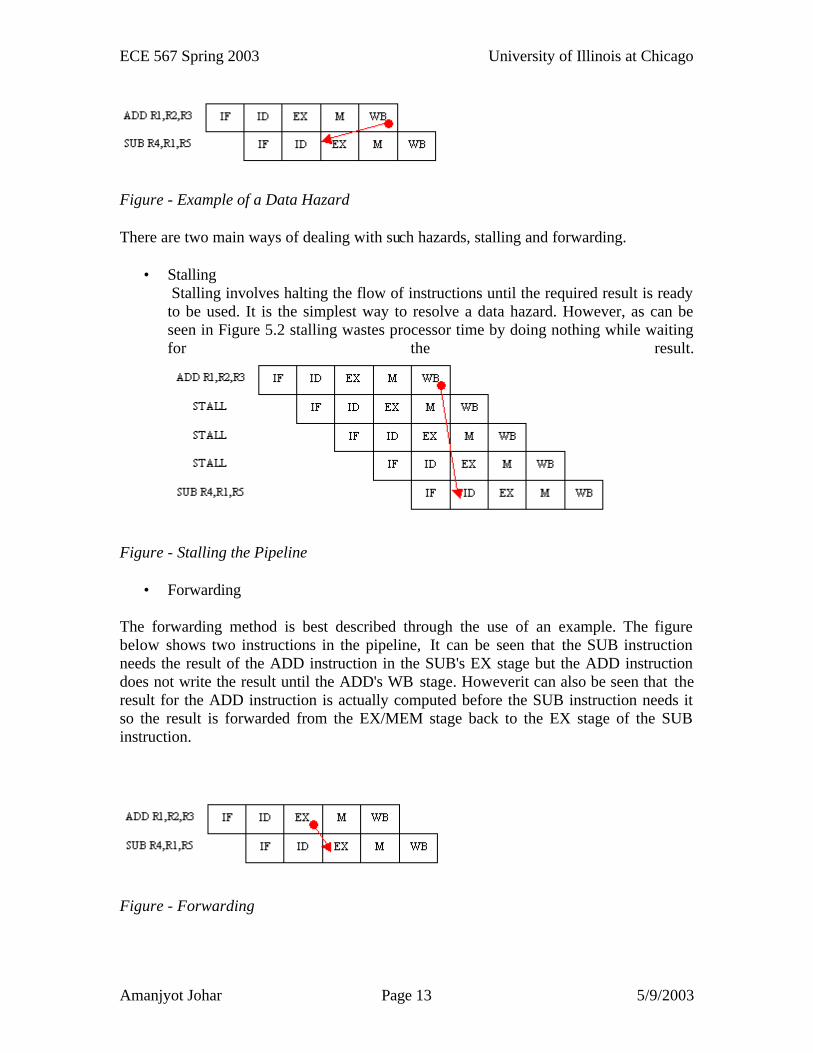
Data Hazards Data Hazards occur when an instruction attempts to use a register whose value depends on the result of previous instructions that have not yet finished.
ECE 567 Spring 2003 University of Illinois at Chicago
Amanjyot Johar Page 13 5/9/2003
Figure - Example of a Data Hazard
There are two main ways of dealing with such hazards, stalling and forwarding.
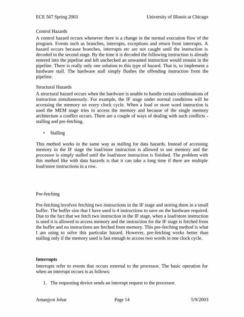
• Stalling Stalling involves halting the flow of instructions until the required result is ready to be used. It is the simplest way to resolve a data hazard. However, as can be seen in Figure 5.2 stalling wastes processor time by doing nothing while waiting for the result.
Figure - Stalling the Pipeline
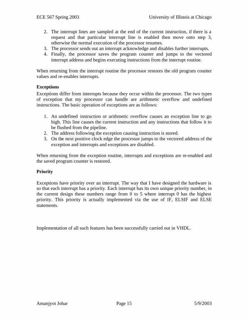
• Forwarding
The forwarding method is best described through the use of an example. The figure below shows two instructions in the pipeline, It can be seen that the SUB instruction needs the result of the ADD instruction in the SUB's EX stage but the ADD instruction does not write the result until the ADD's WB stage. Howeverit can also be seen that the result for the ADD instruction is actually computed before the SUB instruction needs it so the result is forwarded from the EX/MEM stage back to the EX stage of the SUB instruction.
Figure - Forwarding
ECE 567 Spring 2003 University of Illinois at Chicago
Amanjyot Johar Page 14 5/9/2003
Control Hazards A control hazard occurs whenever there is a change in the normal execution flow of the program. Events such as branches, interrupts, exceptions and return from interrupts. A hazard occurs because branches, interrupts etc are not caught until the instruction is decoded in the second stage. By the time it is decoded the following instruction is already entered into the pipeline and left unchecked an unwanted instruction would remain in the pipeline. There is really only one solution to this type of hazard. That is, to implement a hardware stall. The hardware stall simply flushes the offending instruction from the pipeline.
Structural Hazards A structural hazard occurs when the hardware is unable to handle certain combinations of instruction simultaneously. For example, the IF stage under normal conditions will be accessing the memory on every clock cycle. When a load or store word instruction is used the MEM stage tries to access the memory and because of the single memory architecture a conflict occurs. There are a couple of ways of dealing with such conflicts - stalling and pre-fetching.
• Stalling
This method works in the same way as stalling for data hazards. Instead of accessing memory in the IF stage the load/store instruction is allowed to use memory and the processor is simply stalled until the load/store instruction is finished. The problem with this method like with data hazards is that it can take a long time if there are multiple load/store instructions in a row.
Pre-fetching
Pre-fetching involves fetching two instructions in the IF stage and storing them in a small buffer. The buffer size that I have used is 4 instructions to save on the hardware required. Due to the fact that we fetch two instruction in the IF stage, when a load/store instruction is used it is allowed to access memory and the instruction for the IF stage is fetched from the buffer and no instructions are fetched from memory. This pre-fetching method is what I am using to solve this particular hazard. However, pre-fetching works better than stalling only if the memory used is fast enough to access two words in one clock cycle.
Interrupts Interrupts refer to events that occurs external to the processor. The basic operation for when an interrupt occurs is as follows:
1. The requesting device sends an interrupt request to the processor.
ECE 567 Spring 2003 University of Illinois at Chicago
Amanjyot Johar Page 15 5/9/2003
2. The interrupt lines are sampled at the end of the current instruction, if there is a request and that particular interrupt line is enabled then move onto step 3, otherwise the normal execution of the processor resumes.
3. The processor sends out an interrupt acknowledge and disables further interrupts. 4. Finally, the processor saves the program counter and jumps to the vectored
interrupt address and begins executing instructions from the interrupt routine.
When returning from the interrupt routine the processor restores the old program counter values and re-enables interrupts.
Exceptions Exceptions differ from interrupts because they occur within the processor. The two types of exception that my processor can handle are arithmetic overflow and undefined instructions. The basic operation of exceptions are as follows:
1. An undefined instruction or arithmetic overflow causes an exception line to go high. This line causes the current instruction and any instructions that follow it to be flushed from the pipeline.
2. The address following the exception causing instruction is stored. 3. On the next positive clock edge the processor jumps to the vectored address of the
exception and interrupts and exceptions are disabled.
When returning from the exception routine, interrupts and exceptions are re-enabled and the saved program counter is restored.
Priority
Exceptions have priority over an interrupt. The way that I have designed the hardware is so that each interrupt has a priority. Each interrupt has its own unique priority number, in the current design these numbers range from 0 to 5 where interrupt 0 has the highest priority. This priority is actually implemented via the use of IF, ELSIF and ELSE statements.
Implementation of all such features has been successfully carried out in VHDL.
ECE 567 Spring 2003 University of Illinois at Chicago
Amanjyot Johar Page 16 5/9/2003
Conclusions
The RISC processor was implemented and the working was verified at the top level and at the component levels using Simili 2.1 from Symphony EDA. Separate modules have been implemented for the five pipeline stages i.e. instruction-fetch, instruction decode, instruction execute, memory and input access, and memory write-back. The codes from the main functional units are attached in the appendices along with a number of figures illustrating the working of different entities in the processor. The individual components were successfully tested for their functioning. Individual test-benches were generated and all the signals were monitored for their proper functionality. Some test results have been included in the appendices as well. The design functionality was also verified using Synopsys and also the possibility of implementation over a Xilinx module was explored. The code compiled efficiently.
A number of future proposals can be suggested based on the project. They include:
• Development of a 32-bit RISC processor • Development of separate hardware for memory and implementing memory
management sub-routines • Hardware implementation. • Development of a full cache memory
ECE 567 Spring 2003 University of Illinois at Chicago
Amanjyot Johar Page 17 5/9/2003
Appendix: VHDL codes for the Processor: Not all the codes have been listed. The main entities that have been listed here are the pipeline stages, the top level CPU model, the ALU model, the shifter, controller, the hazard detection unit and buffers. library ieee; use ieee.std_logic_1164.all; use ieee.std_logic_arith.all; use ieee.std_logic_signed.all; use ieee.std_logic_unsigned.all; ENTITY AckReg IS PORT(Ack : IN STD_LOGIC_VECTOR(5 DOWNTO 0); clk : IN STD_LOGIC; AckSignals : OUT STD_LOGIC_VECTOR(5 DOWNTO 0)); END ENTITY AckReg; ARCHITECTURE AckReg_behav OF AckReg IS BEGIN name : PROCESS(clk) IS --This variable is used to hold the value of the acknowledgements --This value is defaulted to all ZERO's. VARIABLE regValue : STD_LOGIC_VECTOR(5 DOWNTO 0) := "000000"; BEGIN IF(clk='1') THEN --If the clock goes high then set the acknowledgement --register to the value of the current acknowledgement and output --that result. regValue := Ack; AckSignals <= regValue; END IF; END PROCESS name; END ARCHITECTURE AckReg_behav; library ieee; use ieee.std_logic_1164.all; use ieee.std_logic_arith.all; use ieee.std_logic_signed.all; use ieee.std_logic_unsigned.all; ENTITY ALU IS PORT(RegA, RegB, A_Immed, S_Immed : IN STD_LOGIC_VECTOR(15 DOWNTO 0); mvi_Immed : IN STD_LOGIC_VECTOR(7 DOWNTO 0); alu_sel : IN STD_LOGIC; operation : IN STD_LOGIC_VECTOR(3 DOWNTO 0); res_sel : IN STD_LOGIC_VECTOR(1 DOWNTO 0); result : OUT STD_LOGIC_VECTOR(15 DOWNTO 0); overflow : OUT STD_LOGIC); END ENTITY ALU; ARCHITECTURE structural_ALU OF ALU IS --Declare Signals Needed SIGNAL reg_or_immediate : STD_LOGIC_VECTOR(15 DOWNTO 0); SIGNAL reg_or_simmediate : STD_LOGIC_VECTOR(15 DOWNTO 0); SIGNAL alu_result : STD_LOGIC_VECTOR(15 DOWNTO 0); SIGNAL su_result : STD_LOGIC_VECTOR(15 DOWNTO 0); SIGNAL mvi_result : STD_LOGIC_VECTOR(15 DOWNTO 0); SIGNAL overflow_result : STD_LOGIC; BEGIN select1 : entity risc.selector PORT MAP(RegB, A_Immed, alu_sel, reg_or_immediate);
ECE 567 Spring 2003 University of Illinois at Chicago
Amanjyot Johar Page 18 5/9/2003
select2 : entity risc.selector PORT MAP(RegB, S_Immed, alu_sel, reg_or_simmediate); result1 : entity risc.alu_16 PORT MAP(RegA, reg_or_immediate, operation, overflow_result, alu_result); result2 : entity risc.shift_16 PORT MAP(RegA, reg_or_simmediate, operation(1 downto 0), su_result); result3 : entity risc.mvibox PORT MAP(RegA(7 downto 0), mvi_Immed, operation(0), mvi_result); Final_Results : entity risc.alu_mux PORT MAP(alu_result, su_result, mvi_result, overflow_result, res_sel, result, overflow); END ARCHITECTURE structural_alu; library ieee; use ieee.std_logic_1164.all; use ieee.std_logic_arith.all; use ieee.std_logic_signed.all; use ieee.std_logic_unsigned.all; ENTITY alu_16 IS PORT(a, b : IN STD_LOGIC_VECTOR(15 DOWNTO 0); func : IN STD_LOGIC_VECTOR(3 DOWNTO 0); overflow : OUT STD_LOGIC; c : OUT STD_LOGIC_VECTOR(15 DOWNTO 0)); END ENTITY alu_16; ARCHITECTURE alu_behav OF alu_16 IS BEGIN name : PROCESS(a, b, func) IS VARIABLE signedResult : SIGNED(15 DOWNTO 0); VARIABLE unsignedResult : UNSIGNED(16 DOWNTO 0); VARIABLE temp : STD_LOGIC_VECTOR(15 DOWNTO 0); BEGIN CASE func IS --AND_WORD WHEN "0000" => c <= a and b; overflow <= '0'; --OR WHEN "0001" => c <= a or b; overflow <= '0'; --XOR WHEN "0010" => c <= a xor b; overflow <= '0'; --NOR WHEN "0011" => c <= a nor b;
ECE 567 Spring 2003 University of Illinois at Chicago
Amanjyot Johar Page 19 5/9/2003
overflow <= '0'; --NOT WHEN "0100" => c <= not a; overflow <= '0'; --ADD WHEN "0101" => signedResult := conv_signed(conv_integer(signed(a)) +conv_integer(signed(b)),16); temp := conv_std_logic_vector(signed(a) + signed(b), 16); c <= conv_std_logic_vector(signedResult,16); if(conv_signed(signed(temp),16) >=conv_signed(32768,16) or conv_signed(signed(temp),16) < conv_signed(-32768,32)) then overflow <= '1'; else overflow <= '0'; end if; --SUB WHEN "0110" => signedResult := signed(a) - signed(b); c <= conv_std_logic_vector(signedResult,16); if(conv_integer(signedResult) >=32768 or conv_integer(signedResult) <-32768) then overflow <= '1'; else overflow <= '0'; end if; --ADDu WHEN "0111" => unsignedResult := unsigned(a) + unsigned(b); c <= conv_std_logic_vector(unsignedResult,16); IF(conv_integer(unsignedResult) >= 65536) then overflow <= '1'; ELSE overflow <= '0'; END IF; --SUBu WHEN "1000" => unsignedResult := unsigned(a) - unsigned(b); c <=conv_std_logic_vector(unsignedResult,16); --if(conv_integer(unsignedResult) < 0) then -- overflow <= '1'; --else overflow <= '0'; -- end if; --SLTu WHEN "1001" => if(conv_integer(unsigned(a))<=conv_integer(unsigned(b))) then c <= "0000000000000000"; else c <= "0000000000000001"; end if; overflow <= '0'; --SLT WHEN "1010" => if(conv_integer(signed(a))<=conv_integer(signed(b))) then c<="0000000000000000"; else c<="0000000000000001"; end if;
ECE 567 Spring 2003 University of Illinois at Chicago
Amanjyot Johar Page 20 5/9/2003
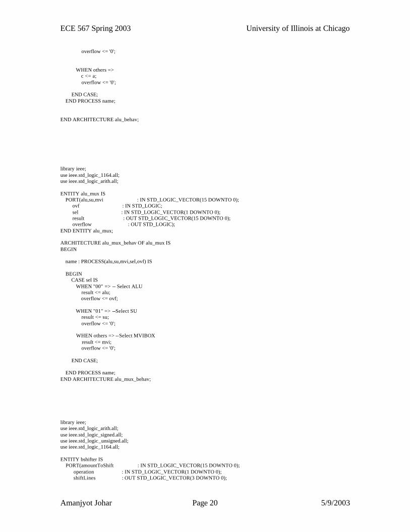
overflow <= '0'; WHEN others => c <= a; overflow <= '0'; END CASE; END PROCESS name; END ARCHITECTURE alu_behav; library ieee; use ieee.std_logic_1164.all; use ieee.std_logic_arith.all; ENTITY alu_mux IS PORT(alu,su,mvi : IN STD_LOGIC_VECTOR(15 DOWNTO 0); ovf : IN STD_LOGIC; sel : IN STD_LOGIC_VECTOR(1 DOWNTO 0); result : OUT STD_LOGIC_VECTOR(15 DOWNTO 0); overflow : OUT STD_LOGIC); END ENTITY alu_mux; ARCHITECTURE alu_mux_behav OF alu_mux IS BEGIN name : PROCESS(alu,su,mvi,sel,ovf) IS BEGIN CASE sel IS WHEN "00" => -- Select ALU result <= alu; overflow <= ovf; WHEN "01" => --Select SU result <= su; overflow <= '0'; WHEN others => --Select MVIBOX result <= mvi; overflow <= '0'; END CASE; END PROCESS name; END ARCHITECTURE alu_mux_behav; library ieee; use ieee.std_logic_arith.all; use ieee.std_logic_signed.all; use ieee.std_logic_unsigned.all; use ieee.std_logic_1164.all; ENTITY bshifter IS PORT(amountToShift : IN STD_LOGIC_VECTOR(15 DOWNTO 0); operation : IN STD_LOGIC_VECTOR(1 DOWNTO 0); shiftLines : OUT STD_LOGIC_VECTOR(3 DOWNTO 0);
ECE 567 Spring 2003 University of Illinois at Chicago
Amanjyot Johar Page 21 5/9/2003
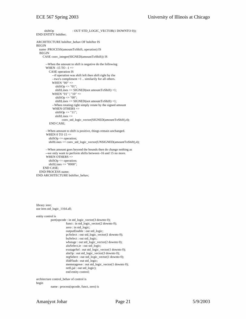
shiftOp : OUT STD_LOGIC_VECTOR(1 DOWNTO 0)); END ENTITY bshifter; ARCHITECTURE bshifter_behav OF bshifter IS BEGIN name :PROCESS(amountToShift, operation) IS BEGIN CASE conv_integer(SIGNED(amountToShift)) IS --When the amount to shift is negative do the following WHEN -15 TO -1 => CASE operation IS --if operation was shift left then shift right by the --two's compliment +1 .. similarily for all others. WHEN "00" => shiftOp <= "01"; shiftLines <= SIGNED(not amountToShift) +1; WHEN "01" | "10" => shiftOp <= "00"; shiftLines <= SIGNED(not amountToShift) +1; --When rotating right simply rotate by the signed amount WHEN OTHERS => shiftOp <= "11"; shiftLines <= conv_std_logic_vector(SIGNED(amountToShift),4); END CASE; --When amount to shift is positive, things remain unchanged. WHEN 0 TO 15 => shiftOp <= operation; shiftLines <= conv_std_logic_vector(UNSIGNED(amountToShift),4); --When amount goes beyond the bounds then do change nothing as --we only want to perform shifts between -16 and 15 no more. WHEN OTHERS => shiftOp <= operation; shiftLines <= "0000"; END CASE; END PROCESS name; END ARCHITECTURE bshifter_behav; library ieee; use ieee.std_logic_1164.all; entity control is port(opcode : in std_logic_vector(3 downto 0); funct : in std_logic_vector(2 downto 0); zero : in std_logic; outputEnable : out std_logic; pcSelect : out std_logic_vector(1 downto 0); buSelect : out std_logic; wbstage : out std_logic_vector(2 downto 0); aluSelect,ie : out std_logic; exstageSel : out std_logic_vector(1 downto 0); aluOp : out std_logic_vector(3 downto 0); regSelect : out std_logic_vector(1 downto 0); ifidFlush : out std_logic; memstagewe : out std_logic_vector(1 downto 0); retfi,jal : out std_logic); end entity control; architecture control_behav of control is begin name : process(opcode, funct, zero) is
ECE 567 Spring 2003 University of Illinois at Chicago
Amanjyot Johar Page 22 5/9/2003
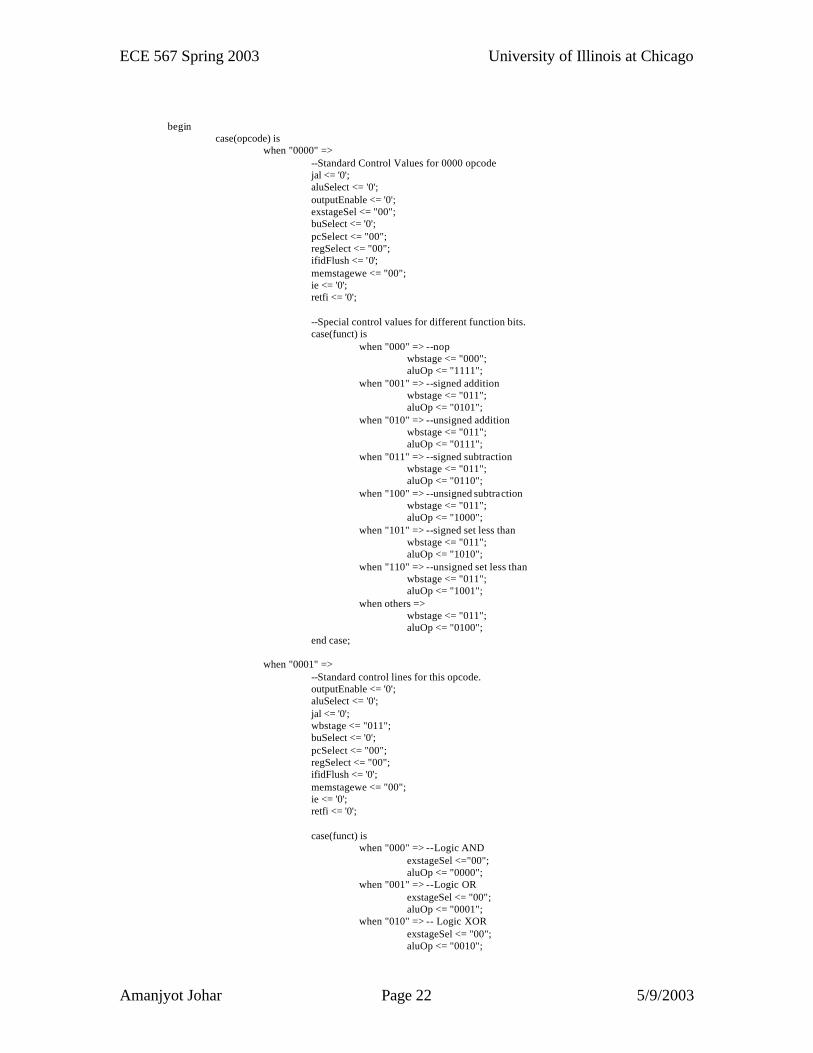
begin case(opcode) is when "0000" => --Standard Control Values for 0000 opcode jal <= '0'; aluSelect <= '0'; outputEnable <= '0'; exstageSel <= "00"; buSelect <= '0'; pcSelect <= "00"; regSelect <= "00"; ifidFlush <= '0'; memstagewe <= "00"; ie <= '0'; retfi <= '0'; --Special control values for different function bits. case(funct) is when "000" => --nop wbstage <= "000"; aluOp <= "1111"; when "001" => --signed addition wbstage <= "011"; aluOp <= "0101"; when "010" => --unsigned addition wbstage <= "011"; aluOp <= "0111"; when "011" => --signed subtraction wbstage <= "011"; aluOp <= "0110"; when "100" => --unsigned subtraction wbstage <= "011"; aluOp <= "1000"; when "101" => --signed set less than wbstage <= "011"; aluOp <= "1010"; when "110" => --unsigned set less than wbstage <= "011"; aluOp <= "1001"; when others => wbstage <= "011"; aluOp <= "0100"; end case; when "0001" => --Standard control lines for this opcode. outputEnable <= '0'; aluSelect <= '0'; jal <= '0'; wbstage <= "011"; buSelect <= '0'; pcSelect <= "00"; regSelect <= "00"; ifidFlush <= '0'; memstagewe <= "00"; ie <= '0'; retfi <= '0'; case(funct) is when "000" => --Logic AND exstageSel <="00"; aluOp <= "0000"; when "001" => --Logic OR exstageSel <= "00"; aluOp <= "0001"; when "010" => -- Logic XOR exstageSel <= "00"; aluOp <= "0010";
ECE 567 Spring 2003 University of Illinois at Chicago
Amanjyot Johar Page 23 5/9/2003
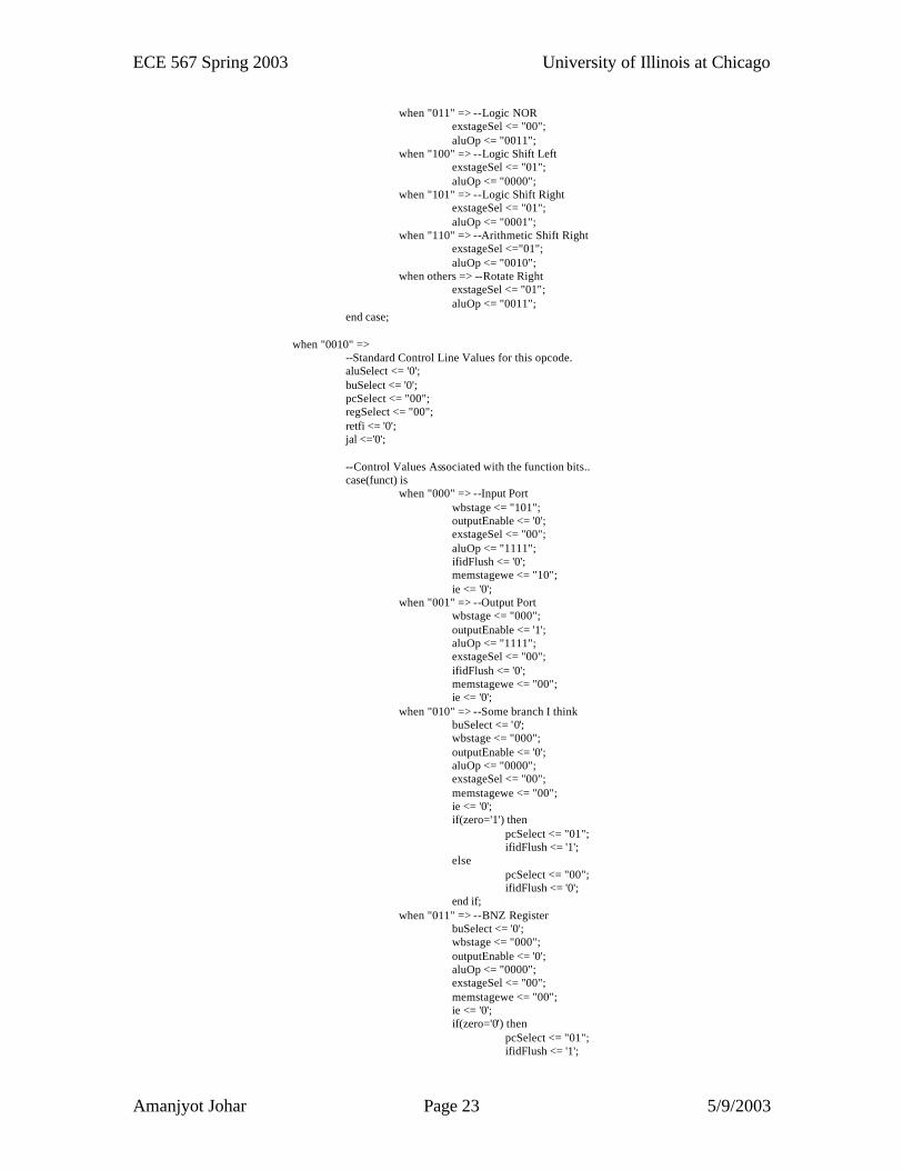
when "011" => --Logic NOR exstageSel <= "00"; aluOp <= "0011"; when "100" => --Logic Shift Left exstageSel <= "01"; aluOp <= "0000"; when "101" => --Logic Shift Right exstageSel <= "01"; aluOp <= "0001"; when "110" => --Arithmetic Shift Right exstageSel <="01"; aluOp <= "0010"; when others => --Rotate Right exstageSel <= "01"; aluOp <= "0011"; end case; when "0010" => --Standard Control Line Values for this opcode. aluSelect <= '0'; buSelect <= '0'; pcSelect <= "00"; regSelect <= "00"; retfi <= '0'; jal <='0'; --Control Values Associated with the function bits.. case(funct) is when "000" => --Input Port wbstage <= "101"; outputEnable <= '0'; exstageSel <= "00"; aluOp <= "1111"; ifidFlush <= '0'; memstagewe <= "10"; ie <= '0'; when "001" => --Output Port wbstage <= "000"; outputEnable <= '1'; aluOp <= "1111"; exstageSel <= "00"; ifidFlush <= '0'; memstagewe <= "00"; ie <= '0'; when "010" => --Some branch I think buSelect <= '0'; wbstage <= "000"; outputEnable <= '0'; aluOp <= "0000"; exstageSel <= "00"; memstagewe <= "00"; ie <= '0'; if(zero='1') then pcSelect <= "01"; ifidFlush <= '1'; else pcSelect <= "00"; ifidFlush <= '0'; end if; when "011" => --BNZ Register buSelect <= '0'; wbstage <= "000"; outputEnable <= '0'; aluOp <= "0000"; exstageSel <= "00"; memstagewe <= "00"; ie <= '0'; if(zero='0') then pcSelect <= "01"; ifidFlush <= '1';
ECE 567 Spring 2003 University of Illinois at Chicago
Amanjyot Johar Page 24 5/9/2003
else pcSelect <= "00"; ifidFlush <= '0'; end if; when others => --No IDEA!! buSelect <= '0'; wbstage <= "000"; outputEnable <= '0'; aluOp <= "0000"; exstageSel <= "00"; pcSelect <= "00"; ie <= '1'; ifidFlush <= '0'; memstagewe <= "00"; end case; when "0011" => if(funct="000") then --this is the JAL register instruction wbstage <= "011"; outputEnable <= '0'; aluOp <= "0000"; exstageSel <= "00"; aluSelect <= '0'; buSelect <= '0'; pcSelect <= "10"; regSelect <= "00"; ifidFlush <= '1'; memstagewe <= "00"; ie <= '0'; retfi <= '0'; jal <='1'; elsif(funct="001") then --this is the RET from Jal instruction.. wbstage <= "000"; outputEnable <= '0'; aluOp <= "0000"; exstageSel <= "00"; aluSelect <= '0'; buSelect <= '0'; pcSelect <= "10"; --new pc value = readOne regSelect <= "00"; ifidFlush <= '0'; memstagewe <= "00"; ie <= '0'; retfi <= '0'; elsif(funct="010") then --this is the RETI instruction aluSelect <= '0'; outputEnable <= '0'; exstageSel <= "00"; buSelect <= '0'; regSelect <= "00"; ifidFlush <= '0'; wbstage <= "000"; memstagewe <= "00"; ie <= '0'; jal <= '0'; pcSelect <="11"; retfi <= '1'; aluOp <= "0000";
ECE 567 Spring 2003 University of Illinois at Chicago
Amanjyot Johar Page 25 5/9/2003
else pcSelect <= "00"; end if; when "0100" => --MVIL and MVIH buSelect <= '0'; pcSelect <= "00"; ifidFlush <= '0'; memstagewe <= "00"; regSelect <= "01"; wbstage <= "011"; exstageSel <= "10"; outputEnable <= '0'; aluSelect <= '0'; retfi <= '0'; ie <= '0'; jal <= '0'; if(funct(0)='0') then --MVIL aluOp <= "0000"; else aluOp<="0001"; end if; when "0101" => -- Standard Control Lines for this opcode buSelect <= '1'; wbstage <= "000"; outputEnable <= '0'; aluOp <= "0000"; exstageSel <= "00"; regSelect <= "01"; memstagewe <= "00"; ie <= '0'; retfi <= '0'; jal <= '0'; --Branch Zero PC Relative if(funct(0)='0') then if(zero='1') then pcSelect <= "01"; ifidFlush <= '1'; else pcSelect <= "00"; ifidFlush <= '0'; end if; end if; --Branch Not Zero PC Relative if(funct(0)='1') then if(zero='0') then pcSelect <= "01"; ifidFlush <= '1'; else pcSelect <= "00"; ifidFlush <= '0'; end if; end if;
ECE 567 Spring 2003 University of Illinois at Chicago
Amanjyot Johar Page 26 5/9/2003
when "0111" => --SLLI and SRLI wbstage <= "011"; exstageSel <= "01"; outputEnable <= '0'; aluSelect <= '1'; buSelect <= '0'; pcSelect <= "00"; regSelect <= "00"; ifidFlush <= '0'; memstagewe <= "00"; ie <= '0'; jal <= '0'; retfi <= '0'; if(funct(0) = '0') then aluOp <= "0000"; else aluOp <= "0001"; end if; when "1000" => --SRAI and RORI wbstage <= "011"; exstageSel <= "01"; outputEnable <= '0'; aluSelect <= '1'; buSelect <= '0'; pcSelect <= "00"; regSelect <= "00"; ifidFlush <= '0'; memstagewe <= "00"; ie <= '0'; retfi <= '0'; jal <= '0'; if(funct(0) = '0') then aluOp <= "0010"; else aluOp <= "0011"; end if; --ADDI when "1001" => wbstage <= "011"; exstageSel <= "00"; outputEnable <= '0'; aluSelect<='1'; aluOp <= "0101"; buSelect <= '0'; pcSelect <= "00"; regSelect <= "00"; ifidFlush <= '0'; memstagewe <= "00"; ie <= '0'; retfi <= '0'; jal <= '0'; --SUBI when "1010" => wbstage <= "011"; exstageSel <= "00"; outputEnable <= '0'; aluSelect<='1';
ECE 567 Spring 2003 University of Illinois at Chicago
Amanjyot Johar Page 27 5/9/2003
aluOp <= "0110"; buSelect <= '0'; pcSelect <= "00"; regSelect <= "00"; ifidFlush <= '0'; memstagewe <= "00"; ie <= '0'; retfi <='0'; jal <= '0'; --LW when "1011" => wbstage <= "001"; exstageSel <= "00"; outputEnable <= '0'; aluSelect<='1'; aluOp <= "0101"; buSelect <= '0'; pcSelect <= "00"; regSelect <= "00"; ifidFlush <= '0'; memstagewe <= "10"; ie <= '0'; retfi <= '0'; jal <= '0'; --SW when "1100" => wbstage <= "000"; exstageSel <= "00"; outputEnable <= '0'; aluSelect<='1'; aluOp <= "0101"; buSelect <= '0'; pcSelect <= "00"; regSelect <= "10"; ifidFlush <= '0'; memstagewe <= "11"; ie <= '0'; retfi <= '0'; jal <= '0'; --Standard Control Values when others => wbstage <= "000"; outputEnable <= '0'; aluOp <= "0000"; exstageSel <= "00"; aluSelect <= '0'; buSelect <= '0'; pcSelect <= "00"; regSelect <= "00"; ifidFlush <= '0'; memstagewe <= "00"; ie <= '0'; retfi <= '0'; jal <= '0'; end case; end process name; end architecture control_behav; library ieee; use ieee.std_logic_1164.all; use ieee.std_logic_arith.all;
ECE 567 Spring 2003 University of Illinois at Chicago
Amanjyot Johar Page 28 5/9/2003
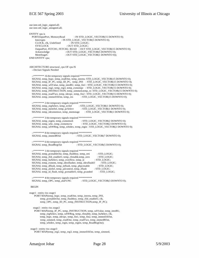
use ieee.std_logic_signed.all; use ieee.std_logic_unsigned.all; ENTITY cpu is PORT(InputPort, MemoryRead : IN STD_LOGIC_VECTOR(15 DOWNTO 0); Interrupts : IN STD_LOGIC_VECTOR(5 DOWNTO 0); CLOCK, clk, Undefined : IN STD_LOGIC; SYSCLOCK : OUT STD_LOGIC; OutputPort, FETCH1, FETCH2, READ : OUT STD_LOGIC_VECTOR(15 DOWNTO 0); Acknowledge : OUT STD_LOGIC_VECTOR(5 DOWNTO 0); MemStageC : OUT STD_LOGIC_VECTOR(1 DOWNTO 0)); END ENTITY cpu; ARCHITECTURE structural_cpu OF cpu IS --Declare Signals Needed --******** 16-bit temporary signals required ********* SIGNAL temp_bupc, temp_readOne, temp_intretu: STD_LOGIC_VECTOR(15 DOWNTO 0); SIGNAL temp_IF_PC, temp_ID_PC, temp_INS : STD_LOGIC_VECTOR(15 DOWNTO 0); SIGNAL temp_wbValue, temp_intoBU, temp_fin1 : STD_LOGIC_VECTOR(15 DOWNTO 0); SIGNAL temp_reg2, temp_reg3, temp_exmempc : STD_LOGIC_VECTOR(15 DOWNTO 0); SIGNAL temp_INSTRUCTION, temp_simmed,temp_re: STD_LOGIC_VECTOR(15 DOWNTO 0); SIGNAL temp_readTwo, temp_idexpc, temp_fin2 : STD_LOGIC_VECTOR(15 DOWNTO 0); SIGNAL temp_immed16Out, temp_res : STD_LOGIC_VECTOR(15 DOWNTO 0); --******** 2-bit temporary singals required ********** SIGNAL temp_regSelect, temp_exSel : STD_LOGIC_VECTOR(1 DOWNTO 0); SIGNAL temp_memSel, temp_pcSelect : STD_LOGIC_VECTOR(1 DOWNTO 0); SIGNAL temp_idexmemwe, temp_memstage : STD_LOGIC_VECTOR(1 DOWNTO 0); --******** 3-bit temporary signals required ********** SIGNAL temp_regtin, temp_exmemwb : STD_LOGIC_VECTOR(2 DOWNTO 0); SIGNAL temp_wbc, temp_exmemcrw : STD_LOGIC_VECTOR(2 DOWNTO 0); SIGNAL temp_wbWReg, temp_wbidex, temp_regin : STD_LOGIC_VECTOR(2 DOWNTO 0); --******** 8-bit temporary signals required ********** SIGNAL temp_immed8Out : STD_LOGIC_VECTOR(7 DOWNTO 0); --******** 6-bit temporary signals required ********** SIGNAL temp_ReadRegOut : STD_LOGIC_VECTOR(5 DOWNTO 0); --******** 1-bit temporary signals required ********** SIGNAL temp_pcenableOut, temp_flushboy, temp_reti : STD_LOGIC; SIGNAL temp_ifid_enableO, temp_rfenable,temp_zero : STD_LOGIC; SIGNAL temp_buSelect, temp_overflow, temp_ie : STD_LOGIC; SIGNAL temp_exmem, temp_idexflusher, temp_idexflushO : STD_LOGIC; SIGNAL temp_dflush, temp_mflush, temp_pbpcenable : STD_LOGIC; SIGNAL temp_aluSel, temp_jalcontrol, temp_iflush : STD_LOGIC; SIGNAL temp_id_flush, temp_pcenableO, temp_pcanded : STD_LOGIC; --******** 4-bit temporary signals required ********** SIGNAL temp_OPC, temp_aluFUNC : STD_LOGIC_VECTOR(3 DOWNTO 0); BEGIN stage1 : entity risc.stage1 PORT MAP(temp_bupc, temp_readOne, temp_intretu, temp_INS, temp_pcenableOut, temp_flushboy, temp_ifid_enableO, clk, temp_OPC, temp_ID_PC, temp_INSTRUCTION,temp_IF_PC); stage2 : entity risc.stage2 PORT MAP(temp_IF_PC, temp_INSTRUCTION, temp_wbValue, temp_intoBU, temp_regSelect, temp_wbWReg, temp_rfenable, temp_buSelect, clk, temp_bupc, temp_idexpc, temp_fin1, temp_fin2, temp_immed16Out, temp_simmed, temp_readOne, temp_readTwo, temp_immed8Out, temp_wbidex, temp_regin, temp_regtin, temp_ReadRegOut); stage3 : entity risc.stage3 PORT MAP(temp_reg2, temp_reg3, temp_immed16Out, temp_simmed,
ECE 567 Spring 2003 University of Illinois at Chicago
Amanjyot Johar Page 29 5/9/2003
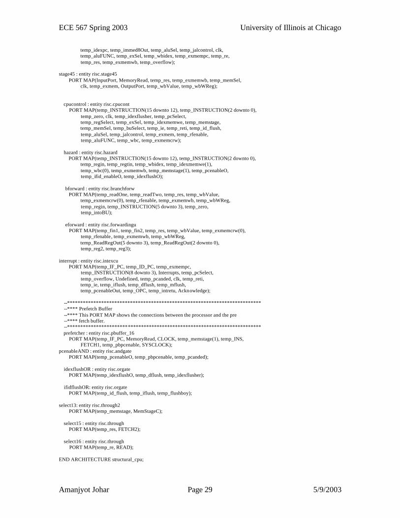
temp_idexpc, temp_immed8Out, temp_aluSel, temp_jalcontrol, clk, temp_aluFUNC, temp_exSel, temp_wbidex, temp_exmempc, temp_re, temp_res, temp_exmemwb, temp_overflow); stage45 : entity risc.stage45 PORT MAP(InputPort, MemoryRead, temp_res, temp_exmemwb, temp_memSel, clk, temp_exmem, OutputPort, temp_wbValue, temp_wbWReg); cpucontrol : entity risc.cpucont PORT MAP(temp_INSTRUCTION(15 downto 12), temp_INSTRUCTION(2 downto 0), temp_zero, clk, temp_idexflusher, temp_pcSelect, temp_regSelect, temp_exSel, temp_idexmemwe, temp_memstage, temp_memSel, temp_buSelect, temp_ie, temp_reti, temp_id_flush, temp_aluSel, temp_jalcontrol, temp_exmem, temp_rfenable, temp_aluFUNC, temp_wbc, temp_exmemcrw); hazard : entity risc.hazard PORT MAP(temp_INSTRUCTION(15 downto 12), temp_INSTRUCTION(2 downto 0), temp_regin, temp_regtin, temp_wbidex, temp_idexmemwe(1), temp_wbc(0), temp_exmemwb, temp_memstage(1), temp_pcenableO, temp_ifid_enableO, temp_idexflushO); bforward : entity risc.branchforw PORT MAP(temp_readOne, temp_readTwo, temp_res, temp_wbValue, temp_exmemcrw(0), temp_rfenable, temp_exmemwb, temp_wbWReg, temp_regin, temp_INSTRUCTION(5 downto 3), temp_zero, temp_intoBU); eforward : entity risc.forwardingu PORT MAP(temp_fin1, temp_fin2, temp_res, temp_wbValue, temp_exmemcrw(0), temp_rfenable, temp_exmemwb, temp_wbWReg, temp_ReadRegOut(5 downto 3), temp_ReadRegOut(2 downto 0), temp_reg2, temp_reg3); interrupt : entity risc.intexcu PORT MAP(temp_IF_PC, temp_ID_PC, temp_exmempc, temp_INSTRUCTION(8 downto 3), Interrupts, temp_pcSelect, temp_overflow, Undefined, temp_pcanded, clk, temp_reti, temp_ie, temp_iflush, temp_dflush, temp_mflush, temp_pcenableOut, temp_OPC, temp_intretu, Acknowledge); --************************************************************************** --**** Prefetch Buffer --**** This PORT MAP shows the connections between the processor and the pre --**** fetch buffer. --************************************************************************** prefetcher : entity risc.pbuffer_16 PORT MAP(temp_IF_PC, MemoryRead, CLOCK, temp_memstage(1), temp_INS, FETCH1, temp_pbpcenable, SYSCLOCK); pcenableAND : entity risc.andgate PORT MAP(temp_pcenableO, temp_pbpcenable, temp_pcanded); idexflushOR : entity risc.orgate PORT MAP(temp_idexflushO, temp_dflush, temp_idexflusher); ifidflushOR: entity risc.orgate PORT MAP(temp_id_flush, temp_iflush, temp_flushboy); select13: entity risc.through2 PORT MAP(temp_memstage, MemStageC); select15 : entity risc.through PORT MAP(temp_res, FETCH2); select16 : entity risc.through PORT MAP(temp_re, READ); END ARCHITECTURE structural_cpu;
ECE 567 Spring 2003 University of Illinois at Chicago
Amanjyot Johar Page 30 5/9/2003
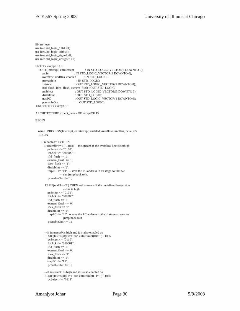
library ieee; use ieee.std_logic_1164.all; use ieee.std_logic_arith.all; use ieee.std_logic_signed.all; use ieee.std_logic_unsigned.all; ENTITY exceptCU IS PORT(Interrupt, enInterrupt : IN STD_LOGIC_VECTOR(5 DOWNTO 0); pcSel : IN STD_LOGIC_VECTOR(1 DOWNTO 0); overflow, undfIns, enabled : IN STD_LOGIC; pcenableIn : IN STD_LOGIC; IntAck : OUT STD_LOGIC_VECTOR(5 DOWNTO 0); ifid_flush, idex_flush, exmem_flush : OUT STD_LOGIC; pcSelect : OUT STD_LOGIC_VECTOR(3 DOWNTO 0); disableInt : OUT STD_LOGIC; trapPC : OUT STD_LOGIC_VECTOR(1 DOWNTO 0); pcenableOut : OUT STD_LOGIC); END ENTITY exceptCU; ARCHITECTURE except_behav OF exceptCU IS BEGIN name : PROCESS(Interrupt, enInterrupt, enabled, overflow, undfIns, pcSel) IS BEGIN IF(enabled='1') THEN IF(overflow='1') THEN --this means if the overflow line is sethigh pcSelect <= "0100"; IntAck <= "000000"; ifid_flush <= '1'; exmem_flush <= '1'; idex_flush <= '1'; disableInt <= '1'; trapPC <= "01"; -- save the PC address in ex stage so that we -- can jump back to it. pcenableOut <= '1'; ELSIF(undfIns='1') THEN --this means if the undefined instruction --line is high pcSelect <= "0101"; IntAck <= "000000"; ifid_flush <= '1'; exmem_flush <= '0'; idex_flush <= '0'; disableInt <= '1'; trapPC <= "10"; -- save the PC address in the id stage so we can -- jump back to it pcenableOut <= '1'; -- if interrupt0 is high and it is also enabled do ELSIF(Interrupt(0)='1' and enInterrupt(0)='1') THEN pcSelect <= "0110"; IntAck <= "000001"; ifid_flush <= '1'; exmem_flush <= '0'; idex_flush <= '1'; disableInt <= '1'; trapPC <= "11"; pcenableOut <= '1'; -- if interrupt1 is high and it is also enabled do ELSIF(Interrupt(1)='1' and enInterrupt(1)='1') THEN pcSelect <= "0111";

ECE 567 Spring 2003 University of Illinois at Chicago
Amanjyot Johar Page 31 5/9/2003
IntAck <= "000010"; ifid_flush <= '1'; exmem_flush <= '0'; idex_flush <= '1'; disableInt <= '1'; trapPC <= "11"; pcenableOut <= '1'; -- if interrupt2 is high and it is also enabled do ELSIF(Interrupt(2)='1' and enInterrupt(2)='1') THEN pcSelect <= "1000"; IntAck <= "000100"; ifid_flush <= '1'; exmem_flush <= '0'; idex_flush <= '1'; disableInt <= '1'; trapPC <= "11"; pcenableOut <= '1'; --if interrupt3 is high and it is also enabled do ELSIF(Interrupt(3)='1' and enInterrupt(3)='1') THEN pcSelect <= "1001"; IntAck <= "001000"; ifid_flush <= '1'; exmem_flush <= '0'; idex_flush <= '1'; d isableInt <= '1'; trapPC <= "11"; pcenableOut <= '1'; -- if interrupt4 is high and it is also enabled do ELSIF(Interrupt(4)='1' and enInterrupt(4)='1') THEN pcSelect <= "1010"; IntAck <= "010000"; ifid_flush <= '1'; exmem_flush <= '0'; idex_flush <= '1'; disableInt <= '1'; trapPC <= "11"; pcenableOut <= '1'; -- if interrupt5 is high and it is also enabled do ELSIF(Interrupt(5)='1' and enInterrupt(5)='1') THEN pcSelect <= "1011"; IntAck <= "100000"; ifid_flush <= '1'; exmem_flush <= '0'; idex_flush <= '1'; disableInt <= '1'; trapPC <= "11"; pcenableOut <= '1'; -- no interrupts or exceptions have occured do nothing. ELSE pcSelect <= "00"&pcSel; IntAck <= "000000"; ifid_flush <= '0'; exmem_flush <= '0'; idex_flush <= '0'; disableInt <= '0'; trapPC <= "00"; pcenableOut <= pcenableIn; END IF; -- Interrupts and Exceptions are not enabled so do nothing. ELSE pcSelect <= "00"&pcSel; IntAck <= "000000"; ifid_flush <= '0'; exmem_flush <= '0';
ECE 567 Spring 2003 University of Illinois at Chicago
Amanjyot Johar Page 32 5/9/2003
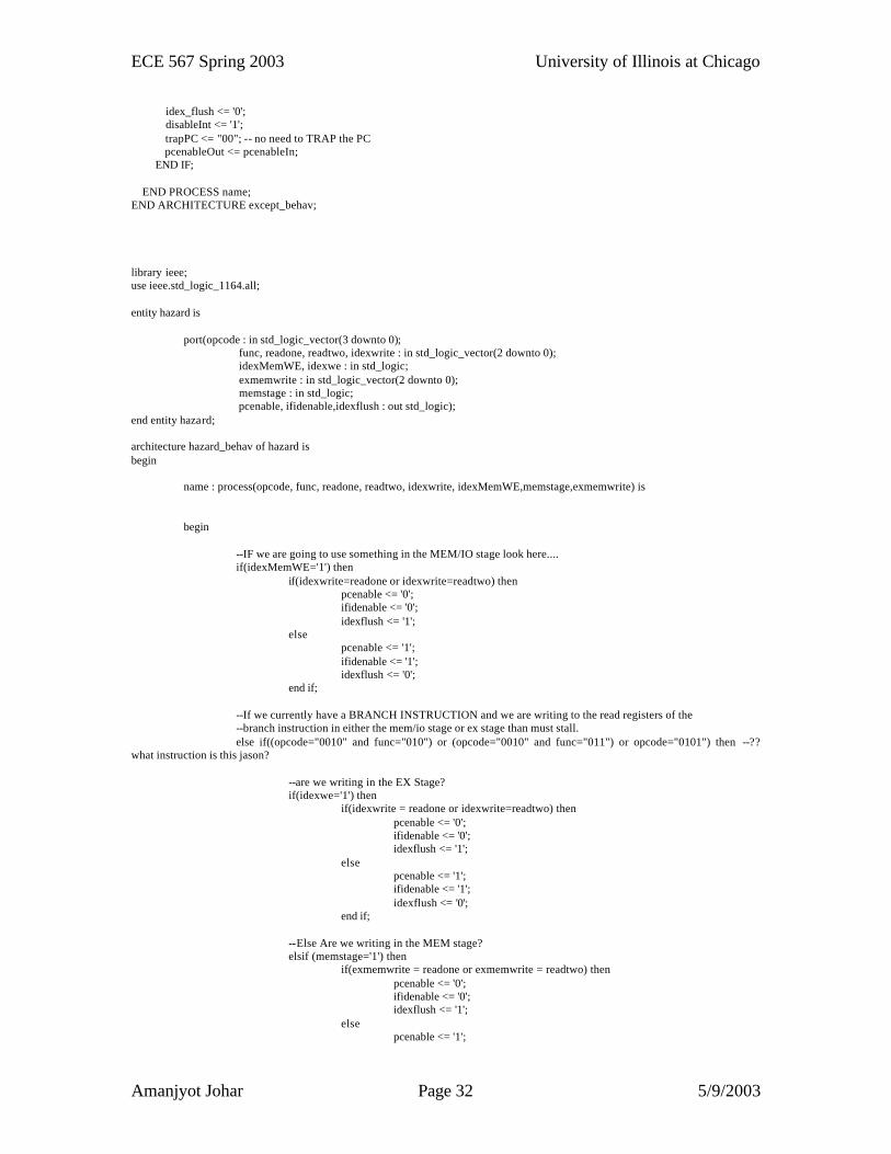
idex_flush <= '0'; disableInt <= '1'; trapPC <= "00"; -- no need to TRAP the PC pcenableOut <= pcenableIn; END IF; END PROCESS name; END ARCHITECTURE except_behav; library ieee; use ieee.std_logic_1164.all; entity hazard is port(opcode : in std_logic_vector(3 downto 0); func, readone, readtwo, idexwrite : in std_logic_vector(2 downto 0); idexMemWE, idexwe : in std_logic; exmemwrite : in std_logic_vector(2 downto 0); memstage : in std_logic; pcenable, ifidenable,idexflush : out std_logic); end entity hazard; architecture hazard_behav of hazard is begin name : process(opcode, func, readone, readtwo, idexwrite, idexMemWE,memstage,exmemwrite) is begin --IF we are going to use something in the MEM/IO stage look here.... if(idexMemWE='1') then if(idexwrite=readone or idexwrite=readtwo) then pcenable <= '0'; ifidenable <= '0'; idexflush <= '1'; else pcenable <= '1'; ifidenable <= '1'; idexflush <= '0'; end if; --If we currently have a BRANCH INSTRUCTION and we are writing to the read registers of the --branch instruction in either the mem/io stage or ex stage than must stall. else if((opcode="0010" and func="010") or (opcode="0010" and func="011") or opcode="0101") then --?? what instruction is this jason? --are we writing in the EX Stage? if(idexwe='1') then if(idexwrite = readone or idexwrite=readtwo) then pcenable <= '0'; ifidenable <= '0'; idexflush <= '1'; else pcenable <= '1'; ifidenable <= '1'; idexflush <= '0'; end if; --Else Are we writing in the MEM stage? elsif (memstage='1') then if(exmemwrite = readone or exmemwrite = readtwo) then pcenable <= '0'; ifidenable <= '0'; idexflush <= '1'; else pcenable <= '1';
ECE 567 Spring 2003 University of Illinois at Chicago
Amanjyot Johar Page 33 5/9/2003
ifidenable <= '1'; idexflush <= '0'; end if; --If neither than do not worry. else pcEnable <='1'; ifidenable <= '1'; idexflush <= '0'; end if; else pcenable <= '1'; ifidenable <= '1'; idexflush <= '0'; end if; end if; end process name; end architecture hazard_behav; library ieee; use ieee.std_logic_1164.all; use ieee.std_logic_arith.all; use ieee.std_logic_signed.all; use ieee.std_logic_unsigned.all; --*********************************************************************** --** Description: This entity structually describes the BUFFER. --****************************************************************************** entity pbuffer is port(ReadAddress, FetchAddress, Data : in std_logic_vector(15 downto 0); pbwe, clk : in std_logic; lastFetchedAddress, instruction : out std_logic_vector(15 downto 0); miss : out std_logic); end entity pbuffer; architecture structural_pbuffer of pbuffer is --Declare Signals Needed signal tag : std_logic_vector(13 downto 0); signal validbit : std_logic; begin select1 : entity risc.pref --This selects either the Register or Immediate Option port map(FetchAddress, Data, ReadAddress(1 downto 0), pbwe, clk, instruction, lastFetchedAddress, tag, validbit); select2 : entity risc.pref_c --This selects either the Register or Shift Immediate Option port map(ReadAddress(15 downto 2), tag, validbit, miss); end architecture structural_pbuffer;
ECE 567 Spring 2003 University of Illinois at Chicago
Amanjyot Johar Page 34 5/9/2003
library ieee; use ieee.std_logic_1164.all; use ieee.std_logic_arith.all; use ieee.std_logic_signed.all; use ieee.std_logic_unsigned.all; --****************************************************************************** --** Description: This entity structually describes the Instruction Fetch stage --** of the pipeline. --****************************************************************************** ENTITY stage1 IS PORT(BU_PC, ReadOne, Intret, Instruction: IN STD_LOGIC_VECTOR(15 DOWNTO 0); PC_enable, IFID_flush, IFID_enable : IN STD_LOGIC; clk : IN STD_LOGIC; OPC : IN STD_LOGIC_VECTOR(3 DOWNTO 0); PC_INCREMENT, InstructionOut : OUT STD_LOGIC_VECTOR(15 DOWNTO 0); pcValue : OUT STD_LOGIC_VECTOR(15 DOWNTO 0) ); END ENTITY stage1; ARCHITECTURE structural_stage1 OF stage1 IS --Declare Signals Needed --********** 16-bit temporary signals needed ********** SIGNAL program_counter, inc_pc : STD_LOGIC_VECTOR(15 DOWNTO 0); SIGNAL temp_newpc : STD_LOGIC_VECTOR(15 DOWNTO 0); --********** 1-bit temporary signals needed *********** SIGNAL pbenable_bit : STD_LOGIC; SIGNAL miss_bit : STD_LOGIC; BEGIN pcselect : entity risc.pcselector PORT MAP(inc_pc, BU_PC, ReadOne, Intret, OPC, temp_newpc); programcounter : entity risc.progc PORT MAP(temp_newpc, clk, PC_enable, program_counter); pluspc : entity risc.incpc PORT MAP(program_counter, inc_pc); ifidpipe : entity risc.IFID PORT MAP(inc_pc, Instruction, clk, IFID_flush, IFID_enable, PC_INCREMENT, InstructionOut); select5 : entity risc.through PORT MAP(program_counter, pcValue); END ARCHITECTURE structural_stage1; library ieee; use ieee.std_logic_1164.all; use ieee.std_logic_arith.all; use ieee.std_logic_signed.all; use ieee.std_logic_unsigned.all; --****************************************************************************** --** Description: This entity structually describes the Instruction Decode stage
ECE 567 Spring 2003 University of Illinois at Chicago
Amanjyot Johar Page 35 5/9/2003
--** of the pipeline. --****************************************************************************** ENTITY stage2 IS PORT(PC, INSTRUCTION, RF_WriteData : IN STD_LOGIC_VECTOR(15 DOWNTO 0); BU_Register : IN STD_LOGIC_VECTOR(15 DOWNTO 0); RegSelect : IN STD_LOGIC_VECTOR(1 DOWNTO 0); RF_WriteReg : IN STD_LOGIC_VECTOR(2 DOWNTO 0); RF_Enable, Branch_Select, clk : IN STD_LOGIC; BU_PC, IDEX_PC,RegOneOut, RegTwoOut: OUT STD_LOGIC_VECTOR(15 DOWNTO 0); R_Immediate, S_Immediate, ReadOne : OUT STD_LOGIC_VECTOR(15 DOWNTO 0); ReadTwo : OUT STD_LOGIC_VECTOR(15 DOWNTO 0); M_Immediate : OUT STD_LOGIC_VECTOR(7 DOWNTO 0); WriteBack, readRegOne, readRegTwo : OUT STD_LOGIC_VECTOR(2 DOWNTO 0); ReadRegisters : OUT STD_LOGIC_VECTOR(5 DOWNTO 0)); END ENTITY stage2; ARCHITECTURE structural_stage2 OF stage2 IS --Declare Signals Needed --******** 3-bit temporary signals needed ******** signal regOneIn, regTwoIn : STD_LOGIC_VECTOR(2 DOWNTO 0); --******** 16-bit temporary signals needed ******** signal readOnea, readTwoa, RI_Immediate : STD_LOGIC_VECTOR(15 DOWNTO 0); signal I_Immediate, SI_Immediate : STD_LOGIC_VECTOR(15 DOWNTO 0); BEGIN mux1 : entity risc.bus_mux_3 PORT MAP(INSTRUCTION(8 downto 6), INSTRUCTION(11 downto 9), RegSelect(0), regOneIn); mux2 : entity risc.bus_mux_3 PORT MAP(INSTRUCTION(5 downto 3), INSTRUCTION(11 downto 9), RegSelect(1), regTwoIn); registerfile : entity risc.regfile PORT MAP(regOneIn, regTwoIn, RF_WriteReg, RF_WriteData, RF_Enable, clk, readOnea, readtwoa); signextender : entity risc.signext PORT MAP(INSTRUCTION(5 downto 0), INSTRUCTION(8 downto 1), RI_Immediate, I_Immediate, SI_Immediate); branchunit : entity risc.branch PORT MAP(PC, I_Immediate, BU_Register, Branch_Select, BU_PC); idexpipeline : entity risc.idex PORT MAP(PC, readOnea, readTwoa, RI_Immediate, SI_Immediate, INSTRUCTION(8 downto 1), clk, INSTRUCTION(11 downto 9), regOneIn, regTwoIn, IDEX_PC, RegOneOut, RegTwoOut, R_Immediate, S_Immediate, M_Immediate, WriteBack, ReadRegisters); select7: entity risc.through PORT MAP(readOnea, readOne); select8: entity risc.through PORT MAP(readTwoa, readTwo); select9: entity risc.through3 PORT MAP(regOneIn, readRegOne); select10: entity risc.through3 PORT MAP(regTwoIn, readRegTwo); END ARCHITECTURE structural_stage2;
ECE 567 Spring 2003 University of Illinois at Chicago
Amanjyot Johar Page 36 5/9/2003
library ieee; use ieee.std_logic_1164.all; use ieee.std_logic_arith.all; use ieee.std_logic_signed.all; use ieee.std_logic_unsigned.all; --****************************************************************************** --** Description: This entity structually describes the Execution Stage of the --** pipeline. --****************************************************************************** ENTITY stage3 IS PORT(RegA, RegB, R_immediate : IN STD_LOGIC_VECTOR(15 DOWNTO 0); idex_pc, S_Immediate : IN STD_LOGIC_VECTOR(15 DOWNTO 0); M_Immediate : IN STD_LOGIC_VECTOR(7 DOWNTO 0); alu_sel, jal_control, clk : IN STD_LOGIC; alu_function : IN STD_LOGIC_VECTOR(3 DOWNTO 0); ex_select : IN STD_LOGIC_VECTOR(1 DOWNTO 0); idexwb : IN STD_LOGIC_VECTOR(2 DOWNTO 0); exmem_pc, exmem_read, exmem_result : OUT STD_LOGIC_VECTOR(15 DOWNTO 0); exmem_wb : OUT STD_LOGIC_VECTOR(2 DOWNTO 0); overflow : OUT STD_LOGIC); END ENTITY stage3; ARCHITECTURE structural_stage3 OF stage3 IS --Declare Signals Needed --******** 3-bit temporary signals needed ******** SIGNAL regOneIn, regTwoIn : STD_LOGIC_VECTOR(2 DOWNTO 0); --******** 16-bit temporary signals needed ******* SIGNAL alu_result, temp_result : STD_LOGIC_VECTOR(15 DOWNTO 0); BEGIN alu : entity risc.alu PORT MAP(regA, regB, R_Immediate, S_Immediate, M_Immediate, alu_sel, alu_function, ex_select, alu_result, overflow); mux1 : entity risc.bus_mux_16 PORT MAP(alu_result, idex_pc, jal_control, temp_result); exmempipeline : entity risc.exmem PORT MAP(idex_pc, temp_result, regB, clk, idexwb, exmem_pc, exmem_result, exmem_read, exmem_wb); END ARCHITECTURE structural_stage3;
ECE 567 Spring 2003 University of Illinois at Chicago
Amanjyot Johar Page 37 5/9/2003
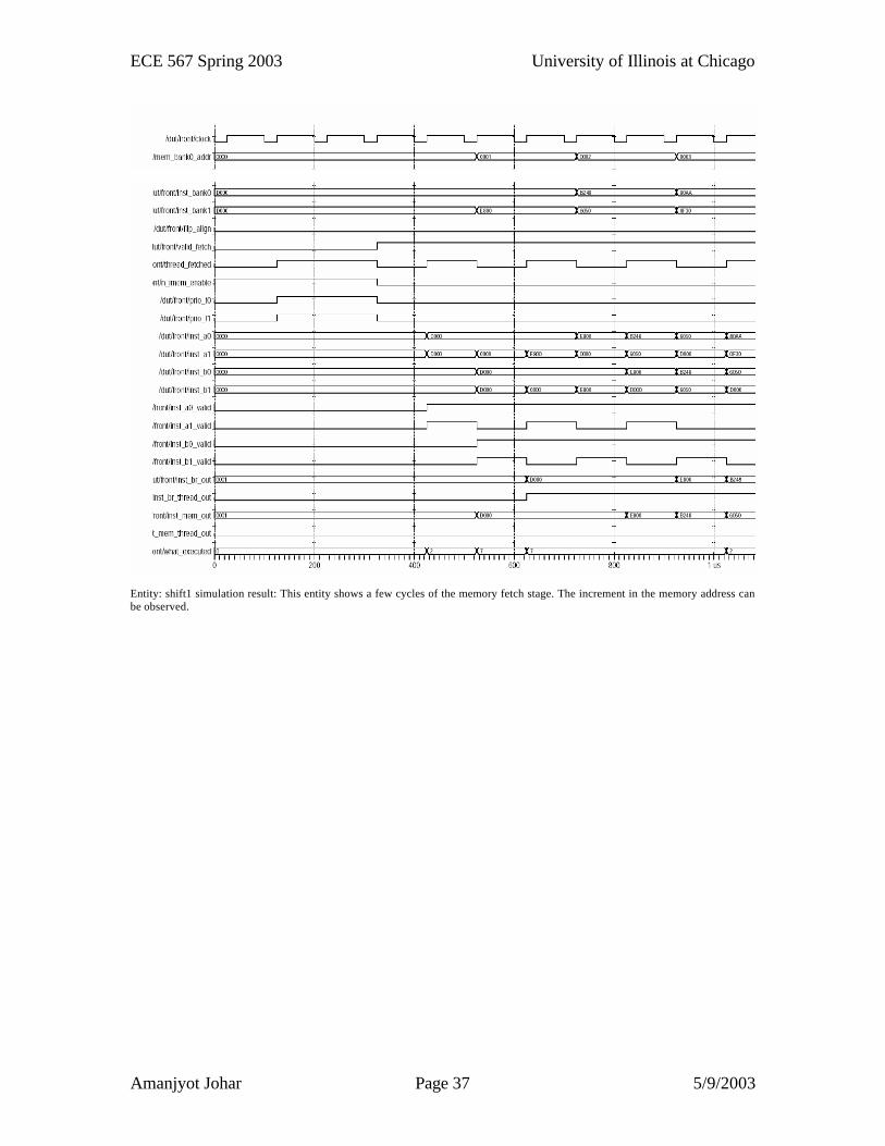
Entity: shift1 simulation result: This entity shows a few cycles of the memory fetch stage. The increment in the memory address can be observed.
ECE 567 Spring 2003 University of Illinois at Chicago
Amanjyot Johar Page 38 5/9/2003
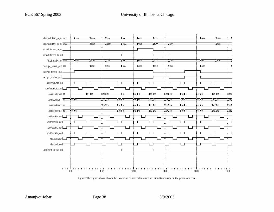
Figure: The figure above shows the execution of several instructions simultaneously on the processor core.
ECE 567 Spring 2003 University of Illinois at Chicago
Amanjyot Johar Page 39 5/9/2003
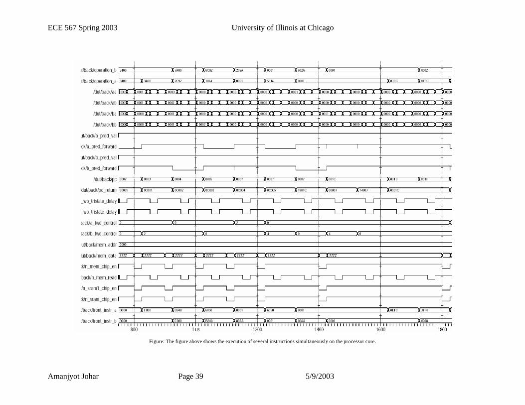
Figure: The figure above shows the execution of several instructions simultaneously on the processor core.
ECE 567 Spring 2003 University of Illinois at Chicago
Amanjyot Johar Page 40 5/9/2003
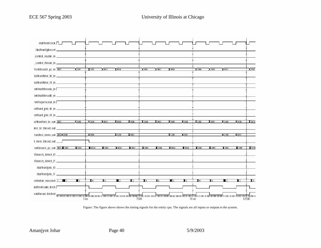
Figure: The figure above shows the timing signals for the entity cpu. The signals are all inputs or outputs to the system.