Embed Size (px)
Citation preview
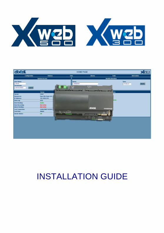
INSTALLATION GUIDE

WARNING:
Use only modems supported by this monitoring unit. Dixell S.p.a can accept no responsibility for possible damage due the usage of not supported modems.
WARNING:
Dixell S.p.a. reserves itself the right to alter this manual without notice. The last version available can be downloaded from the website.
WARNING:
This is a class A product. In a domestic environment this product may cause radio interference in which case the user may be required to take adequate measures.
INDEX 1 CHECK LIST ......................................................................................6 2 TO DO LIST........................................................................................7 3 RS 485 CONNECTION.....................................................................8
3.1 The TTL output.........................................................................11 3.2 Serial address of the instruments .........................................11
4 HOW TO CONNECT XWEB 500..................................................12 4.1 MODEM CONNECTION (“or point to point connection”) ..12
5 Intranet / ethernet connection........................................................27

XWEB SERIES Installation Guide
Pg. 6/33 1592028150 26/06/2007
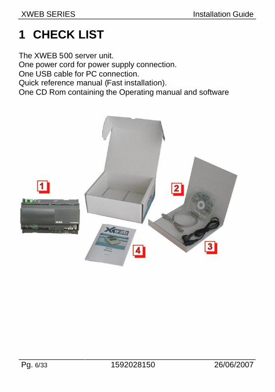
1 CHECK LIST The XWEB 500 server unit. One power cord for power supply connection. One USB cable for PC connection. Quick reference manual (Fast installation). One CD Rom containing the Operating manual and software
XWEB SERIES Installation Guide
26/06/2007 1592028150 Pg. 7/33
2 TO DO LIST Check if the power supply line matches the XWEB 500 specification (90~264 VAC 50~60Hz.). Connect the serial line RS 485 with the adapter provided. Plug-in RJ 45 network cable (not provided).
XWEB SERIES Installation Guide
Pg. 8/33 1592028150 26/06/2007
3 RS 485 CONNECTION To be connected to the serial line all the Dixell Modbus instruments must be provided with direct RS485 terminals or the “TTL”-RS485 interface (XJRS485 or XJ485). Check the instrument manuals for more information. The RS485 line is mainly based on two polarised terminals. Please pay respect to the right sequence for all the devices connected to the serial line. Follow these important instructions : The RS485 serial line must reach all the instruments where they are installed. Make sure of the wire polarities when screwing them into the instrument terminals. The cable must have 2 or 3 wires with shield, minimum section 0,5mm2 (eg. the BELDEN 8772). From the XWEB 500 position the cable reaches all the instrument positions. Do not execute loops or derivations:
XWEB SERIES Installation Guide
26/06/2007 1592028150 Pg. 9/33
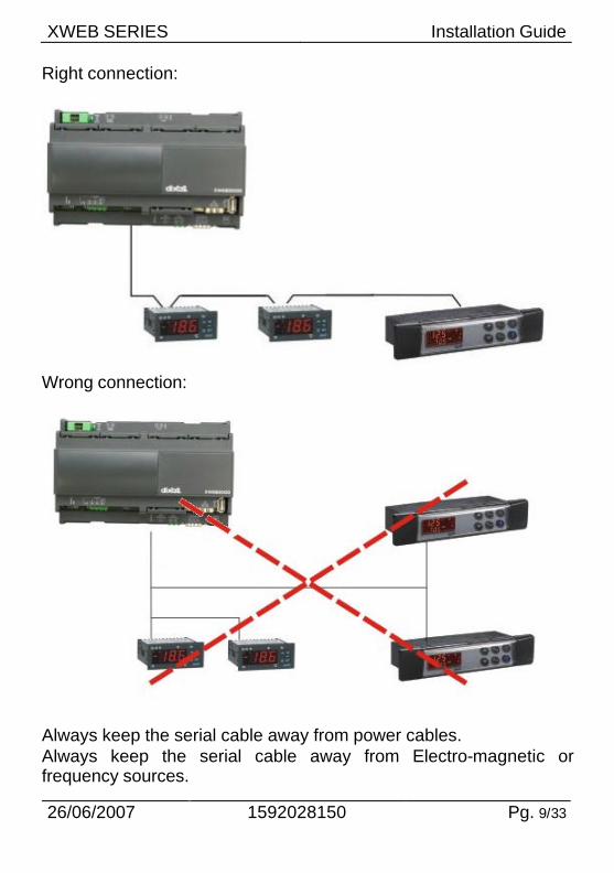
Right connection:
Wrong connection:
Always keep the serial cable away from power cables. Always keep the serial cable away from Electro-magnetic or frequency sources.
XWEB SERIES Installation Guide
Pg. 10/33 1592028150 26/06/2007
Do not connect shield to ground. Do not connect the “Gnd (ground)” terminal. Remember to draw a map of the line. This will help you to find errors if something is wrong. The instrument with RS485 have “+” and “-“ terminals, respect the polarity. To keep the line balanced it is necessary a 100 Ohm resistor at the end of the line (you can use the RS 485+ and RS 485- terminals of the last instrument connected).
XWEB SERIES Installation Guide
26/06/2007 1592028150 Pg. 11/33
3.1 The TTL output The instrument with RS485 on board does not need any kind of external interface module. For instruments with an external interface: keep the TTL cable away from power cables or frequency sources. The XJ485 external interface must be connected with a TTL cable to the instrument with TTL compatibility. 3.2 Serial address of the instruments Each instrument must be defined by its unique address. Check the address into the Adr parameter value of each instruments. Take reference to the instruction manual of the instrument itself to find the right procedure to enter the programming and set the value. The easiest way to work with the category functions is to set the addresses progressively for similar groups of instruments which have the same application.
XWEB SERIES Installation Guide
Pg. 12/33 1592028150 26/06/2007
4 HOW TO CONNECT XWEB 500 It is possible to connect to XWEB 500 whether via USB cable or via Ethernet cable. 4.1 MODEM CONNECTION (“or point to point
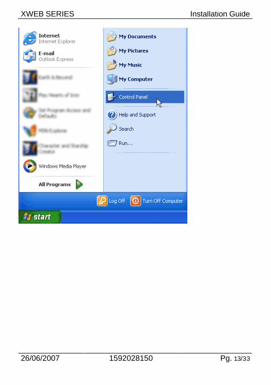
connection”) It represents the most common method where the LAN (intranet / Ethernet / internet) is not available. It is strongly advised to use a dedicated telephone line. IMPORTANT: Use exclusively modem devices approved by Dixell. Remember that many modems are not compatible with Linux. The list of compatible models can be found under the menu: Configuration – System - Modem. In Windows XP, you will use the "New Connection Wizard". 1. From the Start menu, select Control Panel.
XWEB SERIES Installation Guide
26/06/2007 1592028150 Pg. 13/33
XWEB SERIES Installation Guide
Pg. 14/33 1592028150 26/06/2007
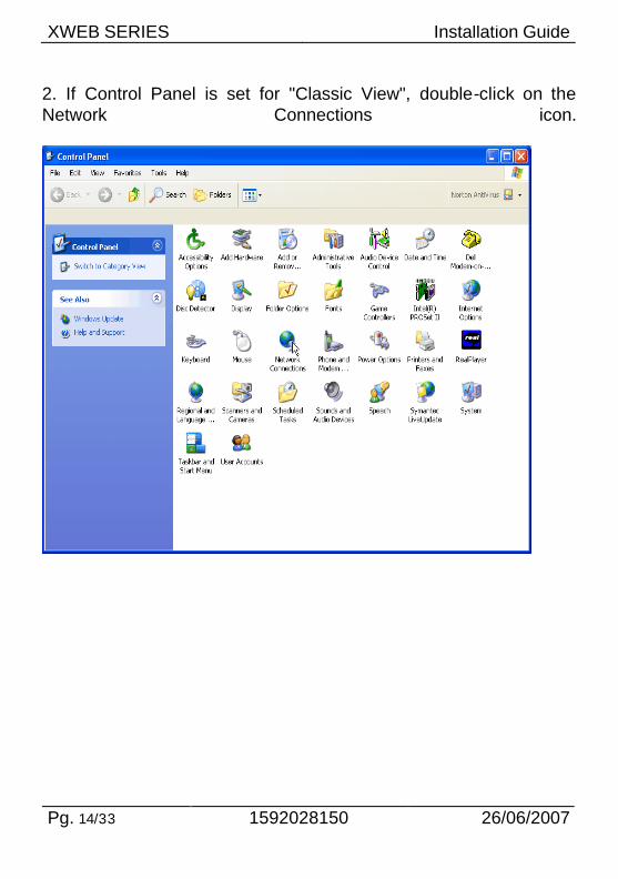
2. If Control Panel is set for "Classic View", double-click on the Network Connections icon.
XWEB SERIES Installation Guide
26/06/2007 1592028150 Pg. 15/33
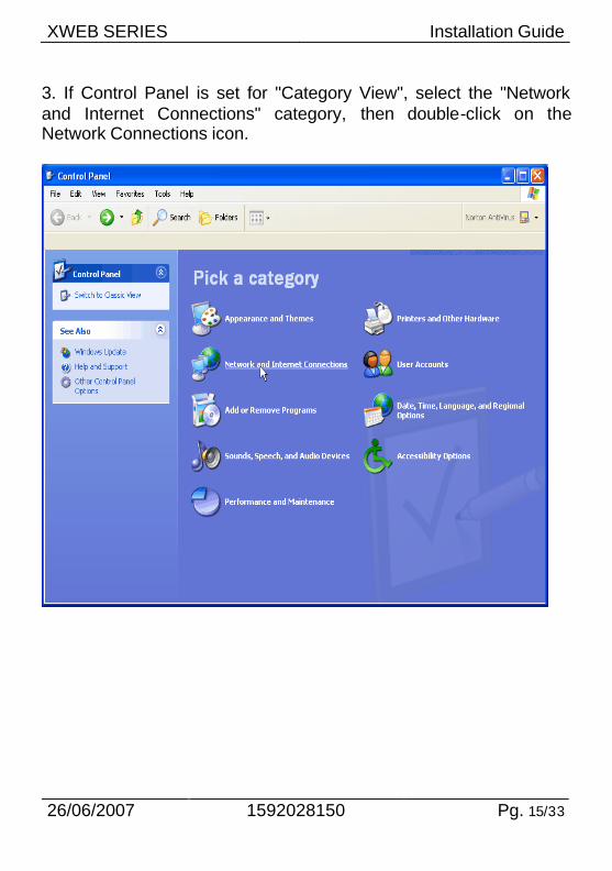
3. If Control Panel is set for "Category View", select the "Network and Internet Connections" category, then double-click on the Network Connections icon.
XWEB SERIES Installation Guide
Pg. 16/33 1592028150 26/06/2007
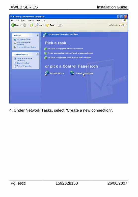
4. Under Network Tasks, select "Create a new connection".
XWEB SERIES Installation Guide
26/06/2007 1592028150 Pg. 17/33
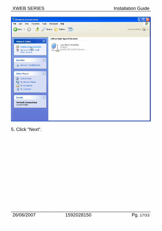
5. Click "Next".
XWEB SERIES Installation Guide
Pg. 18/33 1592028150 26/06/2007
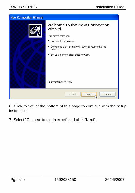
6. Click "Next" at the bottom of this page to continue with the setup instructions. 7. Select "Connect to the Internet" and click "Next".
XWEB SERIES Installation Guide
26/06/2007 1592028150 Pg. 19/33
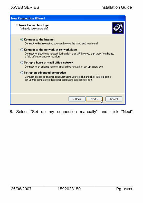
8. Select "Set up my connection manually" and click "Next".
XWEB SERIES Installation Guide
Pg. 20/33 1592028150 26/06/2007
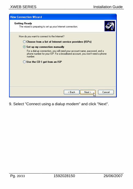
9. Select "Connect using a dialup modem" and click "Next".
XWEB SERIES Installation Guide
26/06/2007 1592028150 Pg. 21/33
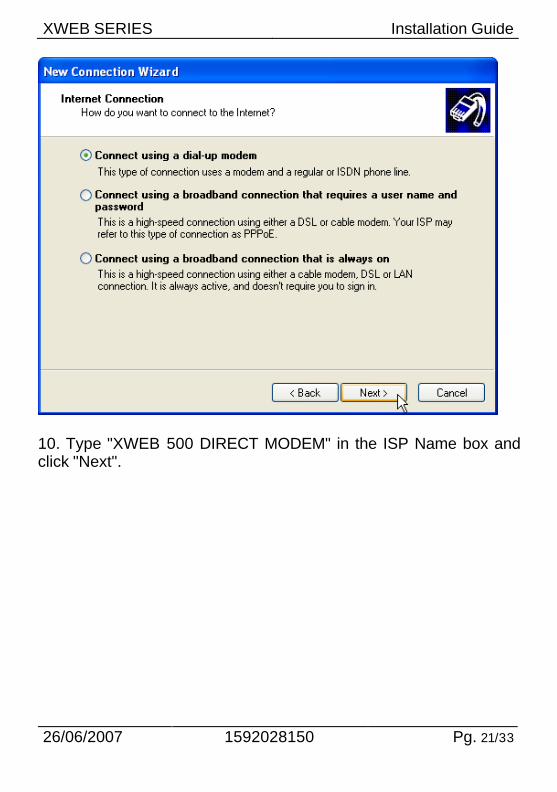
10. Type "XWEB 500 DIRECT MODEM" in the ISP Name box and click "Next".
XWEB SERIES Installation Guide
Pg. 22/33 1592028150 26/06/2007
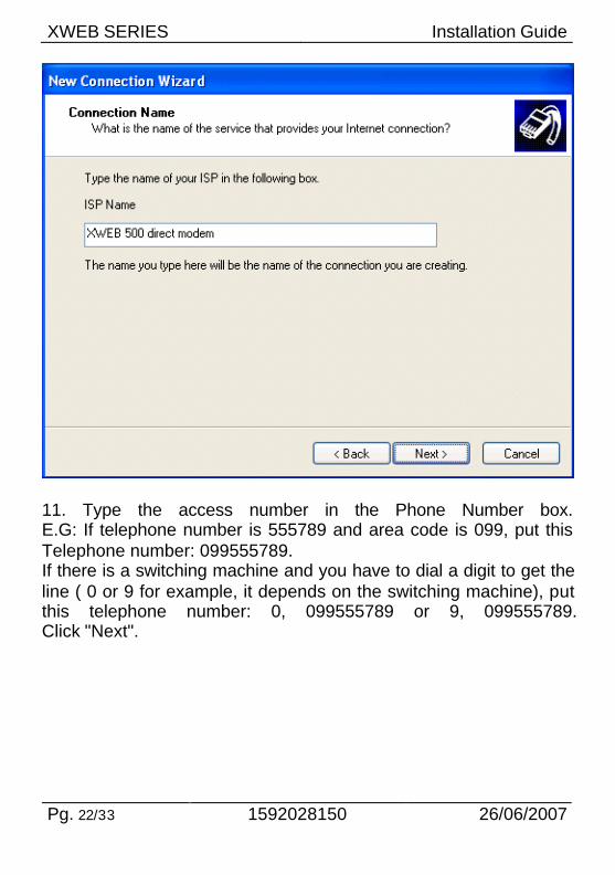
11. Type the access number in the Phone Number box. E.G: If telephone number is 555789 and area code is 099, put this Telephone number: 099555789. If there is a switching machine and you have to dial a digit to get the line ( 0 or 9 for example, it depends on the switching machine), put this telephone number: 0, 099555789 or 9, 099555789. Click "Next".
XWEB SERIES Installation Guide
26/06/2007 1592028150 Pg. 23/33
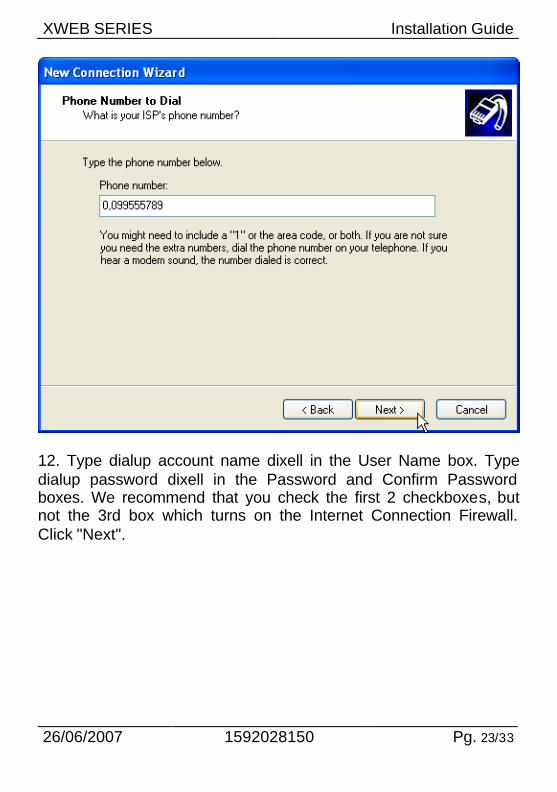
12. Type dialup account name dixell in the User Name box. Type dialup password dixell in the Password and Confirm Password boxes. We recommend that you check the first 2 checkboxes, but not the 3rd box which turns on the Internet Connection Firewall. Click "Next".
XWEB SERIES Installation Guide
Pg. 24/33 1592028150 26/06/2007
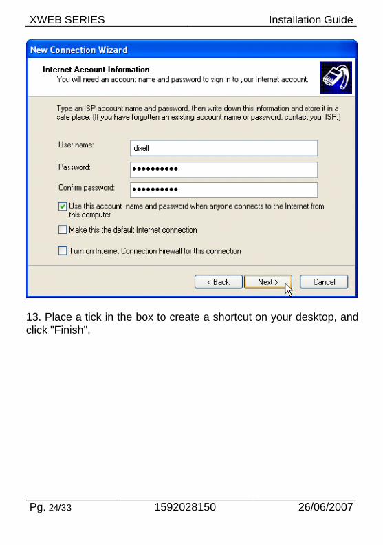
13. Place a tick in the box to create a shortcut on your desktop, and click "Finish".
XWEB SERIES Installation Guide
26/06/2007 1592028150 Pg. 25/33
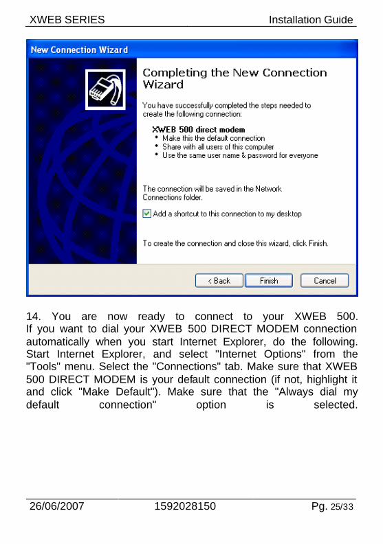
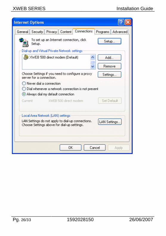
14. You are now ready to connect to your XWEB 500. If you want to dial your XWEB 500 DIRECT MODEM connection automatically when you start Internet Explorer, do the following. Start Internet Explorer, and select "Internet Options" from the "Tools" menu. Select the "Connections" tab. Make sure that XWEB 500 DIRECT MODEM is your default connection (if not, highlight it and click "Make Default"). Make sure that the "Always dial my default connection" option is selected.
XWEB SERIES Installation Guide
Pg. 26/33 1592028150 26/06/2007
XWEB SERIES Installation Guide
26/06/2007 1592028150 Pg. 27/33
5 Intranet / ethernet connection The Intranet or Ethernet connection should be initially managed by the net administrator which will assign one free IP address to reach the Server. This number is an example of what you should expect: http://192.168.000.111. After receiving the address from your network Administrator the XWEB 500 must be set with this number. The Intranet method allows the connection to interact with XWEB 500 from all the PC Clients. Insert the net address assigned by the administrator into the Browser address bar. Bookmark the address with personalised name for the future connections. Internet connection It is necessary to have a STATIC IP address for the XWEB 500 which is normally assigned by the Provider of your internet services (ISP). The Internet connection allows XWEB 500 to be reached from all PC-clients. Insert the net address assigned by the administrator into the Browser address bar. Bookmark the address with personalised name for the future connections. Ask your provider for more details about the rent of a the static IP. This the internet system requirements for the best result: Wide band connection At least 1 static IP address for the XWEB 500. The internet connection is established through a device called Router that receives and sends the data as interface between an Intranet and Internet. The Provider also assigns the address of the router that is called IP WAN. Remember that the default value of the IP of the XWEB 500 is: 192.168.0.200. Depending on the contract the Provider can also supply the router,
XWEB SERIES Installation Guide
Pg. 28/33 1592028150 26/06/2007
otherwise the user can buy it separately. ALWAYS: ask qualified personnel for the router installation by using this information. Used ports that are mapped to the LAN side: 80 (used for the HTTP access) 22 (used for SSH connection) 443 (used for SSL protected connection) 10000 (used for the internal modules of the system) The above ports are all related to the XWEB 500 IP address 192.168.0.150. While the ports on the WAN side are: Telnet (to configure the router from a remote, also via Internet). HTTP (To access the XWEB 500). If working with the router GATEWAY and DNS check your Internet contract details. Depending on your network topology you may need a reverse NAT on port 80. It is not enough to link port 80 on the router side to port 80 on intranet side. Some firewall or Router need also the reverse NAT.

XWEB SERIES Installation Guide
26/06/2007 1592028150 Pg. 29/33
XWEB SERIES Installation Guide
Pg. 30/33 1592028150 26/06/2007
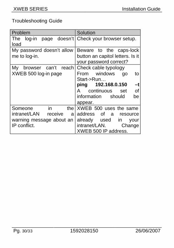
Troubleshooting Guide Problem Solution The log-in page doesn’t load
Check your browser setup.
My password doesn’t allow me to log-in.
Beware to the caps-lock button an capitol letters. Is it your password correct?
My browser can’t reach XWEB 500 log-in page
Check cable typology From windows go to Start->Run… ping 192.168.0.150 –t A continuous set of information should be appear.
Someone in the intranet/LAN receive a warning message about an IP conflict.
XWEB 500 uses the same address of a resource already used in your intranet/LAN. Change XWEB 500 IP address.
XWEB SERIES Installation Guide
26/06/2007 1592028150 Pg. 31/33
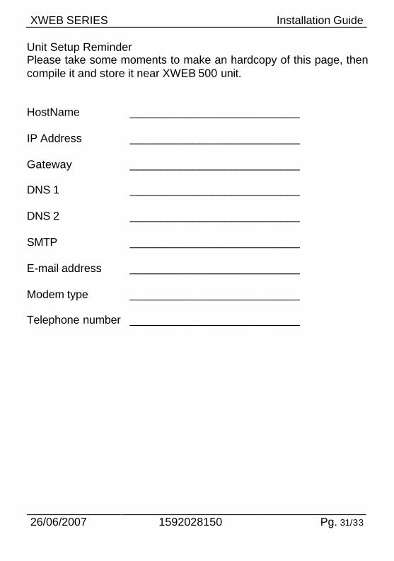
Unit Setup Reminder Please take some moments to make an hardcopy of this page, then compile it and store it near XWEB 500 unit. HostName
___________________________
IP Address
___________________________
Gateway
___________________________
DNS 1
___________________________
DNS 2
___________________________
SMTP
___________________________
E-mail address
___________________________
Modem type
___________________________
Telephone number
___________________________

XWEB SERIES Installation Guide
Pg. 32/33 1592028150 26/06/2007
Notes ________________________________________________________________________________________________________________________________________________________________________________________________________________________________________________________________________________________________________________________________________________________________________________________________________________________________________________________________________________________________________________________________________________________________________________________________________________________________________________________________________________________________________________________________________________________________________________________________________________________________________________________________________________________________________________________________________________________________________________________________________________________________________________________________________________________________________________________________________________________________________________________________________________________________________________________________________________________________________________________________________________________________________________________________________________________________________________________________________________________________________________________________________________________________________________________________________________________________________________________________________________________________________________________________________________________________________________________________

XWEB SERIES QUICK REFERENCE GUIDE
Dixell S.p.a. Z.I. Via dell’Industria, 27 32010 Pieve d’Alpago (BL) ITALY tel. +39 - 0437 - 98 33 - fax +39 - 0437 - 98 93 13 E-mail: [email protected] http://www.dixell.com


![Stevenson, Sir Steve - [Agatha Mistery 02] La perla de Bengala (r1.3 Piolin).pdf](https://img.pdfslide.us/doc/110x75/55cf93e4550346f57b9eb070/stevenson-sir-steve-agatha-mistery-02-la-perla-de-bengala-r13-piolinpdf.jpg)