Embed Size (px)
Citation preview
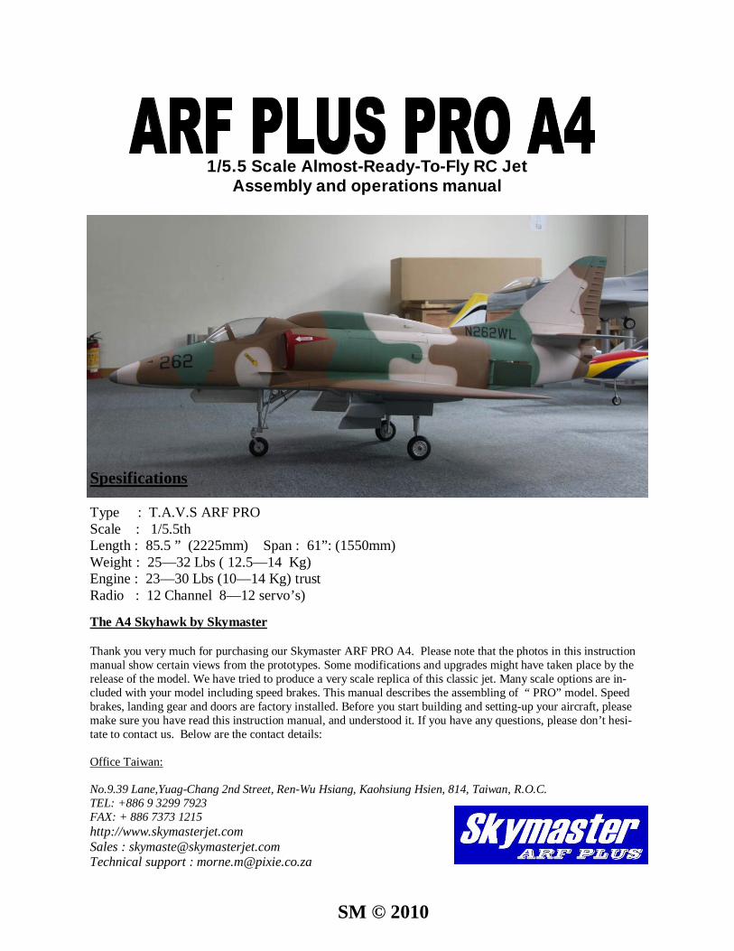
1/5.5 Scale Almost-Ready-To-Fly RC Jet Assembly and operations manual
The A4 Skyhawk by Skymaster Thank you very much for purchasing our Skymaster ARF PRO A4. Please note that the photos in this instruction manual show certain views from the prototypes. Some modifications and upgrades might have taken place by the release of the model. We have tried to produce a very scale replica of this classic jet. Many scale options are in-cluded with your model including speed brakes. This manual describes the assembling of “ PRO” model. Speed brakes, landing gear and doors are factory installed. Before you start building and setting-up your aircraft, please make sure you have read this instruction manual, and understood it. If you have any questions, please don’t hesi-tate to contact us. Below are the contact details: Office Taiwan: No.9.39 Lane,Yuag-Chang 2nd Street, Ren-Wu Hsiang, Kaohsiung Hsien, 814, Taiwan, R.O.C. TEL: +886 9 3299 7923 FAX: + 886 7373 1215 http://www.skymasterjet.com Sales : [email protected] Technical support : [email protected]
Spesifications Type : T.A.V.S ARF PRO Scale : 1/5.5th Length : 85.5 ” (2225mm) Span : 61”: (1550mm) Weight : 25—32 Lbs ( 12.5—14 Kg) Engine : 23—30 Lbs (10—14 Kg) trust Radio : 12 Channel 8—12 servo’s)
SM © 2010
Index: INTRODUCTION....................................................................................................................................... 3
DISCLAIMER..............................................................................................................................................3 WARNING…...............................................................................................................................................3 ARF PAINT.................................................................................................................................................4 FINISHING YOUR WHITE VIPER ARF......................................................................................................4 HANDLING & TRANSPORTING ...............................................................................................................5 LIVE HINGE ……………………………..……….........................................................................................5
TOOL LIST................................................................................................................................................ 6 HEALTH…..................................................................................................................................................7 GENERAL ASSEMBLY TECHNIQUES..................................................................................................…7 RADIO EQUIPMENT & ACCESSORIES…………….................................................................................8 KIT CONTENTS…….……………...............................................................................................................9 OPTIONAL PARTS………………..……………….....................................................................................10 CONTROL LINKAGES ............................................................................................................................12 WINGS......................................................................................................................................................12 STABILIZERS...........................................................................................................................................15 FIN & RUDDER....................................................................................................................................... 16 FUSELAGE.............................................................................................................................................. 17 TAILPIPE………………………………………………………………………………………………………….19 FUEL CELLS…………………………………………………………………………………………………...…19 FUEL DIAGRAM………………………….………………………………………………………………………20 AIR SYSTEM .......................................................................................................................................... 21 AIR DIAGRAM......................................................................................................................................... 22 TURBINE INSTALLATION……………………………………………………………………………………....23 COCKPIT & CANOPY…......................................................................................................................... 24 EQUIPMENT INSTALLATION INTO THE F80 ARF………...……............................................................25 BEFORE YOU FLY.................................................................................................................................. 26 OPTIONAL SCALE PARTS……………………………………………………………………………………...28
P-2
Assembly & Operation Manual
Assembly & Operation Manual
INTRODUCTION
Thank you for purchasing Skymaster arf pro A4! We have put a lot of effort and time into this model. We at Skymaster strive to be a market leader in the ARF— jet market. We were the first company to pro-duce ARF—jets in the world and we would like to continue being amongst the best. Although we have made every effort that this model was fit for shipping, we would like you to inspect the contends and call your nearest dealer immediately if any defects or missing parts are spotted! This manual will allow you to duplicate the factory prototypes.
LIABILITY You have acquired a kit, which can be assembled into a fully working R/C model when fitted out with suitable accessories, as described in the instruction manual with the kit. However, as manufacturers, we at Skymaster are not in a position to influence the way you build and operate your model, and we have no control over the methods you use to install, operate and maintain the radio control system compo-nents. For this reason we are obliged to deny all liability for loss, damage or costs which are incurred due to the incompetent or incorrect application and operation of our products, or which are connected with such operation in any way. Unless otherwise prescribed by binding law, the obligation of the Sky-master company to pay compensation is excluded, regardless of the legal argument employed. This ap-plies to personal injury, death, damage to buildings, loss of turnover and business, interruption of busi-ness or other direct and indirect consequent damages. In all circumstances our total liability is limited to the amount which you actually paid for this model. BY OPERATING THIS MODEL YOU ASSUME FULL RESPONSIBILITY FOR YOUR ACTIONS. It is important to understand that Skymaster, is unable to monitor whether you follow the instructions contained in this instruction manual regarding the construction, operation and maintenance of the air-craft, nor whether you install and use the radio control system correctly. For this reason we at Skymaster are unable to guarantee, or provide, a contractual agreement with any individual or company that the model you have made will function correctly and safely. You, as operator of the model, must rely upon your own expertise and judgment in acquiring and operating this model.
WARNING This ‘jet’ aircraft is a high-end product and can create an enormous risk for both pilot and spectators, if not handled with care, and used according to the instructions. Make sure that you operate your A4 ac-cording to the AMA rules, or those laws and regulations governing model flying in the country of use. The engine, landing gear, servos, linkages and control surfaces have to be attached properly. Please use only the recommended servos and accessories. Make sure that the ‘Centre of Gravity’ is located in the recommended place. Use the nose heavy end of the CG range for your first flights. A tail heavy plane can be an enormous danger for you and all spectators. Fix any weights, and heavy items like bat-teries, very securely into the plane. Make sure that the plane is secured properly when you start the en-gine. Have a helper hold your plane from the nose before you start the engine. Make sure that all spec-tators are far behind, or far in front, of the aircraft when running up the engine. Make sure that you range check your R/C system thoroughly before the 1st flight. It is absolutely necessary to range check your complete R/C installation first WITHOUT the engine running. Leave the transmitter antenna re-tracted, and check the distance you can walk before ‘fail-safe’ occurs. Then start the engine, run at about half throttle and repeat this range check. Make sure that there is no range reduction before ‘fail-safe’ occurs. If the range with engine running is less then with the engine off, please DON’T FLY at that time. Make sure that your wing spar tube is not damaged. Check that the anti-rotation dowels for the wings are not loose. Check that the wing, stab, fin and nose retaining bolts are tight. Please don’t ignore our warnings, or those provided by other manufacturers. They refer to things and processes which, if ignored, could result in permanent damage or fatal injury. Secure the plane before starting engine.
P-3
Assembly & Operation Manual
ARF Paint The color finish on your Skymaster A4 arf pro model was applied out of the mould. We have used only the highest standard automotive paints to finish your model. Should you damage the finish, Skymaster stock the color paint and hardener required for the repair. A good automotive spray painter should also be able to mix and supply the correct samples for repair. If you have no experience in the use of these paints, it will be best to seek assistance. Do not leave your model unprotected in the sun! always cover your model or park it in the shade. Extreme temperatures will damage the paint! Finishing Your All White A4 ARF PRO It is always best to fully assemble the model before painting. By doing so no damage or glue prints will ruin the paint. The all white model will have some release agent on the surfaces. Use #1000 wet and dry paper to sand the entire model. Mould lines can be sanded and filled using normal automotive fillers. Please be extra careful when sanding near the hinge line! The hinges can easily be damaged. When masking and painting please make sure the control surfaces are not bend past 90—180 degrees extensively. This will cause the hinges to crack and may cause flutter. The rudder and clear canopy are not installed. It is best to install these components after painting was done.
P-4
Assembly & Operation Manual
HANDLING & TRANSPORTING
Composite models are very light but strong. These characteristics do have a down side! It is brittle. Take care when handling your model. DO NOT ATTEMPT TO PICK UP AN FULLY FUELED MODEL BY THE LEADING EDGE BY YOURSELF! The leading edges will crack and delami-nate. Full size jets have specially marked access points for the hooks of cranes! Inspect your model before and after a rough landing. Make sure all parts are safe and sound. Inspect model before and after transport. A sudden stop can easily cause an unnoticed dent! The wings and tails are very flight worthy structures. They are light and extremely strong , how-ever, they will dent if mishandled. Always support these structures on clean soft foam rubber.
LIVE HINGE Skymaster utilize this system of hinging control surfaces because it is a very strong hinge system and is accomplished at the factory. Occasionally, because of climatic changes, the bottom surfaces may “catch” or inter-fere with control travel surface actuation. Should this happen, use a fine abrasive strip to further bevel the L.E. of the control surface. CAUTIONS: Do not apply any primer or paint to the underside of the main surface trail-ing edge. Prior to each flight, check that the ailerons and elevators actuate properly, up and down. Inspect the live hinges on a regular basis. If some cracks occur please repair asap with special hinge tape available from Skymaster or its dealers.
P-5
Tools and Adhesives Tools etc:
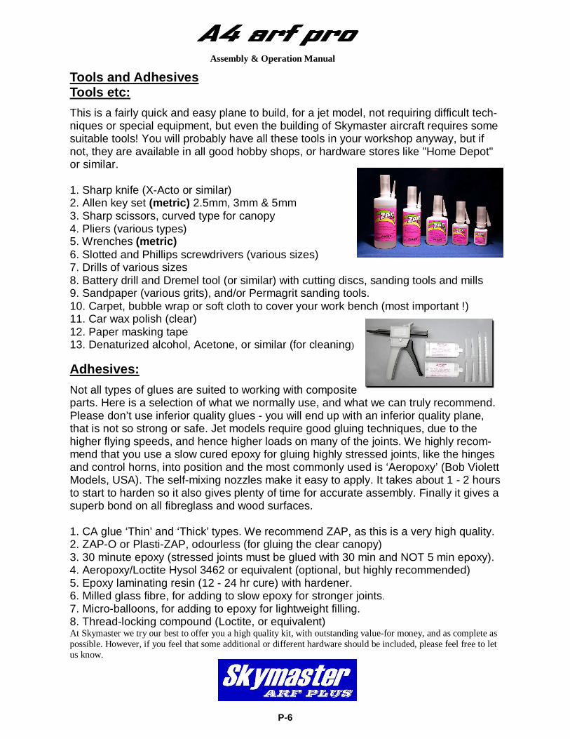
This is a fairly quick and easy plane to build, for a jet model, not requiring difficult tech-niques or special equipment, but even the building of Skymaster aircraft requires some suitable tools! You will probably have all these tools in your workshop anyway, but if not, they are available in all good hobby shops, or hardware stores like "Home Depot" or similar. 1. Sharp knife (X-Acto or similar) 2. Allen key set (metric) 2.5mm, 3mm & 5mm 3. Sharp scissors, curved type for canopy 4. Pliers (various types) 5. Wrenches (metric) 6. Slotted and Phillips screwdrivers (various sizes) 7. Drills of various sizes 8. Battery drill and Dremel tool (or similar) with cutting discs, sanding tools and mills 9. Sandpaper (various grits), and/or Permagrit sanding tools. 10. Carpet, bubble wrap or soft cloth to cover your work bench (most important !) 11. Car wax polish (clear) 12. Paper masking tape 13. Denaturized alcohol, Acetone, or similar (for cleaning) Adhesives:
Not all types of glues are suited to working with composite parts. Here is a selection of what we normally use, and what we can truly recommend. Please don’t use inferior quality glues - you will end up with an inferior quality plane, that is not so strong or safe. Jet models require good gluing techniques, due to the higher flying speeds, and hence higher loads on many of the joints. We highly recom-mend that you use a slow cured epoxy for gluing highly stressed joints, like the hinges and control horns, into position and the most commonly used is ‘Aeropoxy’ (Bob Violett Models, USA). The self-mixing nozzles make it easy to apply. It takes about 1 - 2 hours to start to harden so it also gives plenty of time for accurate assembly. Finally it gives a superb bond on all fibreglass and wood surfaces. 1. CA glue ‘Thin’ and ‘Thick’ types. We recommend ZAP, as this is a very high quality. 2. ZAP-O or Plasti-ZAP, odourless (for gluing the clear canopy) 3. 30 minute epoxy (stressed joints must be glued with 30 min and NOT 5 min epoxy). 4. Aeropoxy/Loctite Hysol 3462 or equivalent (optional, but highly recommended) 5. Epoxy laminating resin (12 - 24 hr cure) with hardener. 6. Milled glass fibre, for adding to slow epoxy for stronger joints. 7. Micro-balloons, for adding to epoxy for lightweight filling. 8. Thread-locking compound (Loctite, or equivalent) At Skymaster we try our best to offer you a high quality kit, with outstanding value-for money, and as complete as possible. However, if you feel that some additional or different hardware should be included, please feel free to let us know.
Assembly & Operation Manual
P-6
Assembly & Operation Manual
HEALTH Use a mask (available at auto paint stores) to protect from inhaling the glass or carbon fiber dust. Use this mask whenever you are sanding or cutting fiberglass or carbon fiber materials. Use a charcoal filter paint mask (available at auto paint supply stores) when spraying any primer or paint. Spray out of doors or in a properly vented spray booth. Use safety glasses any time rotary tools, such as Dremel cut-off disc or Perma-Grit cutters, are being used.
GENERAL ASSEMBLY TECHNIQUES We recommend to wax the model before assembling. This will help protect the finish from an epoxy finger print. Wax will not help for CA glues! Extra glue, extra paint, extra resin will add up to a heavy model. Plan before you glue! The glass cloth side of parts to glue, should be sanded with #80 grit paper for best glue adhesion. Support the fuselage on foam pads. Skymaster makes every attempt to insure that the parts fit. However, due to manufac-turing tolerances, some parts may fit a little tight. Always trial fit parts and adjust if needed. Only use high quality adhesives such as the ZAP products from Pacer Technology. For extremely high stress areas we recommend “Aeropoxy.” It is the strongest and best gripping adhesive we have found. If fuel or grease are on the surface, first clean with acetone or thinners. Clean off all excess glue—excess glue is excess weight. Always check the outside skin of the model to look for any glue residue and remove it with Acetone before it cures. “Aeropoxy” is tough to remove once it has thoroughly cured.
P-7
Radio equipment Failure to use the recommended servos, output arms, extensions, and hardware may result in a loss of control! Throughout this manual we make use of various types of servos and radio equipment! We have used JR equipment during the installation process. If you make use of an-other manufacturer, please use equipment with similar specifications! The A4 will require extension leads! Please use high quality extension leads. Make use of ceramic non ferrite cores if leads exceeds 1 meter. The trend nowadays is to use dual battery management systems and dual RX equip-ment. With the introduction of 2.4 Ghz even quad RX systems are considered as nor-mal for a jet model. Always center and install the correct output arms while on the bench, once the servo is in the aircraft access to the servo arm screw is sometimes limited. Do not save any money when buying radio equipment. The price of servo’s are far from the price of replacing the entire model. REMEMBER: The best equipment is only as good as the weakest link. Ask your-self if this servo or link or lead etc is worthy of my trust to protect my very large investment... Accessories
1. 2 DS8411 servo’s for the elevator. 2. 1 DS8411 for rudder. 3. 2 DS8411 servo’s for ailerons 4. 2 DS8511 servo’s for flaps 5. 1 JR577 steering servo. 6. 3 JR577servos for Landing Gear, Door and Brake valves or check next line. 7. 1 Airpower EV5U valve + 1 x EV2U valve for landing gear + doors + brakes 8. 1 EV2U valve for speed brake 9. Powerbox Royal with build in matchbox function. 10. Pneumatic support set for landing gear 11. Turbine motor, with thrust range between 10kg and 14kg, with accessories. 12. Fuel tubing, Hopper tank (or BVM UAT), festo fittings, fuel filters, fuel tube etc. 13. Cable ties in various lengths.
Did you understand everything in this manual completely?
Then, and only then, let’s start assembling your A4. If not, please read it again before you start the assembly.
Assembly & Operation Manual
P-8
Kit Contents
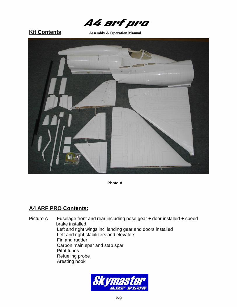
A4 ARF PRO Contents: Picture A Fuselage front and rear including nose gear + door installed + speed brake installed. Left and right wings incl landing gear and doors installed Left and right stabilizers and elevators Fin and rudder Carbon main spar and stab spar Pitot tubes Refueling probe Aresting hook
Assembly & Operation Manual
P-9
Photo A
Assembly & Operation Manual
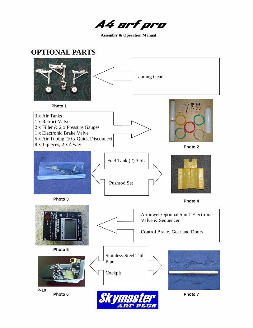
OPTIONAL PARTS
P-10
Landing Gear
3 x Air Tanks 1 x Retract Valve 2 x Filler & 2 x Pressure Gauges 1 x Electronic Brake Valve 5 x Air Tubing, 10 x Quick Disconnect 8 x T-pieces, 2 x 4 way
Pushrod Set
Fuel Tank (2) 3.5L
Airpower Optional 5 in 1 Electronic Valve & Sequencer Control Brake, Gear and Doors
Photo 2
Photo 1
Photo 3 Photo 4
Photo 5
Photo 7
Stainless Steel Tail Pipe Cockpit
Photo 6
Assembly & Operation Manual
P-11
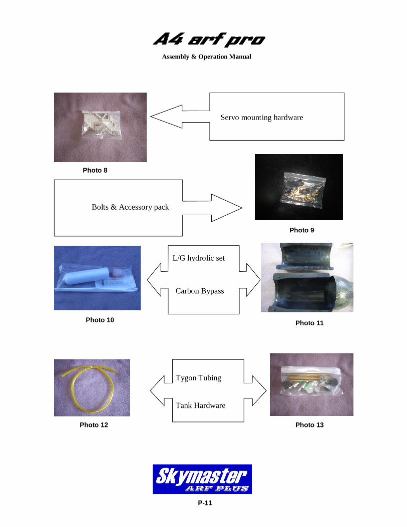
Servo mounting hardware
Bolts & Accessory pack
Carbon Bypass
L/G hydrolic set
Photo 9
Photo 8
Photo 10 Photo 11
Photo 13
Tygon Tubing Tank Hardware
Photo 12
Assembly & Operation Manual
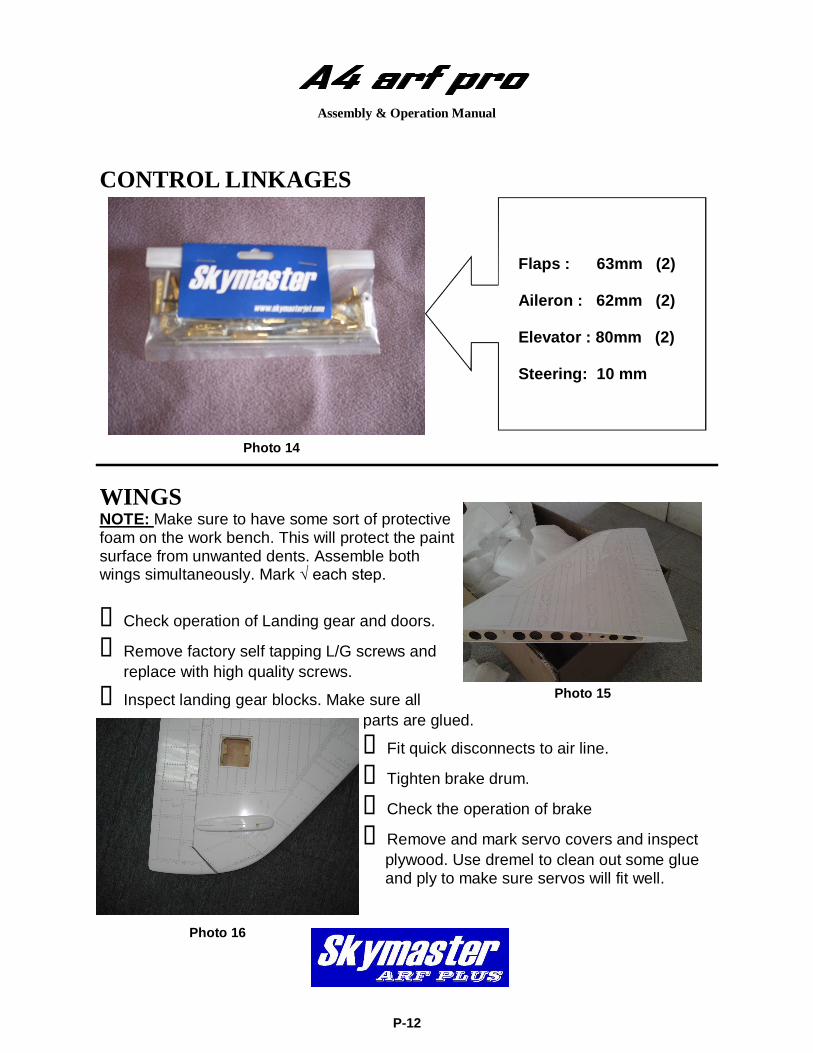
CONTROL LINKAGES
Flaps : 63mm (2) Aileron : 62mm (2) Elevator : 80mm (2) Steering: 10 mm
WINGS NOTE: Make sure to have some sort of protective foam on the work bench. This will protect the paint surface from unwanted dents. Assemble both wings simultaneously. Mark √ each step.
Check operation of Landing gear and doors.
Remove factory self tapping L/G screws and replace with high quality screws.
Inspect landing gear blocks. Make sure all parts are glued.
Fit quick disconnects to air line.
Tighten brake drum.
Check the operation of brake
Remove and mark servo covers and inspect plywood. Use dremel to clean out some glue and ply to make sure servos will fit well.
P-12
Photo 14
Photo 15
Photo 16
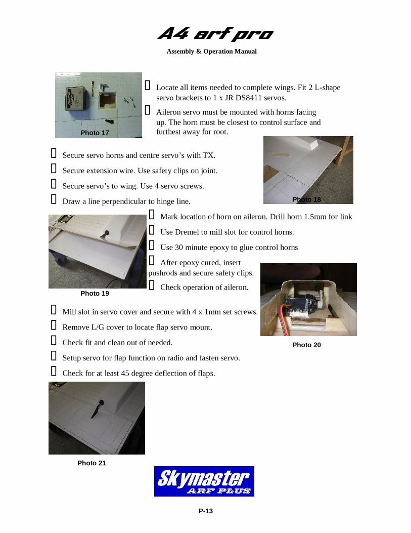
Locate all items needed to complete wings. Fit 2 L-shape servo brackets to 1 x JR DS8411 servos.
Aileron servo must be mounted with horns facing up. The horn must be closest to control surface and furthest away for root.
Secure servo horns and centre servo’s with TX.
Secure extension wire. Use safety clips on joint.
Secure servo’s to wing. Use 4 servo screws.
Draw a line perpendicular to hinge line.
Mark location of horn on aileron. Drill horn 1.5mm for link
Use Dremel to mill slot for control horns.
Use 30 minute epoxy to glue control horns
After epoxy cured, insert pushrods and secure safety clips.
Check operation of aileron.
Mill slot in servo cover and secure with 4 x 1mm set screws.
Remove L/G cover to locate flap servo mount.
Check fit and clean out of needed.
Setup servo for flap function on radio and fasten servo.
Check for at least 45 degree deflection of flaps.
P-13
Assembly & Operation Manual
Photo 17
Photo 18
Photo 19
Photo 20
Photo 21
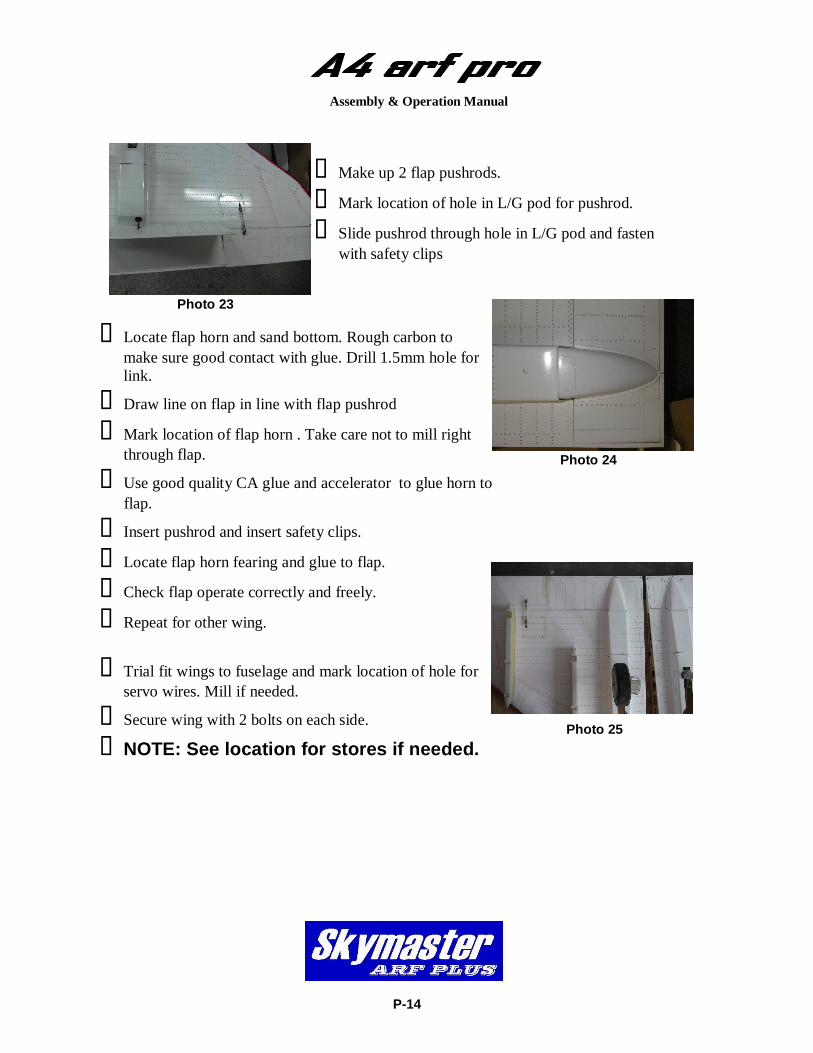
Make up 2 flap pushrods.
Mark location of hole in L/G pod for pushrod.
Slide pushrod through hole in L/G pod and fasten with safety clips
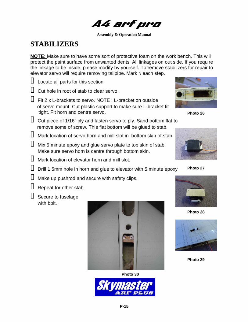
Locate flap horn and sand bottom. Rough carbon to make sure good contact with glue. Drill 1.5mm hole for link.
Draw line on flap in line with flap pushrod
Mark location of flap horn . Take care not to mill right through flap.
Use good quality CA glue and accelerator to glue horn to flap.
Insert pushrod and insert safety clips.
Locate flap horn fearing and glue to flap.
Check flap operate correctly and freely.
Repeat for other wing.
Trial fit wings to fuselage and mark location of hole for servo wires. Mill if needed.
Secure wing with 2 bolts on each side. NOTE: See location for stores if needed.
P-14
Assembly & Operation Manual
Photo 23
Photo 24
Photo 25
Assembly & Operation Manual
STABILIZERS NOTE: Make sure to have some sort of protective foam on the work bench. This will protect the paint surface from unwanted dents. All linkages on out side. If you require the linkage to be inside, please modify by yourself. To remove stabilizers for repair to elevator servo will require removing tailpipe. Mark √ each step.
Locate all parts for this section
Cut hole in root of stab to clear servo.
Fit 2 x L-brackets to servo. NOTE : L-bracket on outside of servo mount. Cut plastic support to make sure L-bracket fit tight. Fit horn and centre servo.
Cut piece of 1/16” ply and fasten servo to ply. Sand bottom flat to remove some of screw. This flat bottom will be glued to stab.
Mark location of servo horn and mill slot in bottom skin of stab.
Mix 5 minute epoxy and glue servo plate to top skin of stab. Make sure servo horn is centre through bottom skin.
Mark location of elevator horn and mill slot.
Drill 1.5mm hole in horn and glue to elevator with 5 minute epoxy
Make up pushrod and secure with safety clips.
Repeat for other stab.
Secure to fuselage with bolt.
P-15
Photo 26
Photo 27
Photo 30
Photo 28
Photo 29
Assembly & Operation Manual
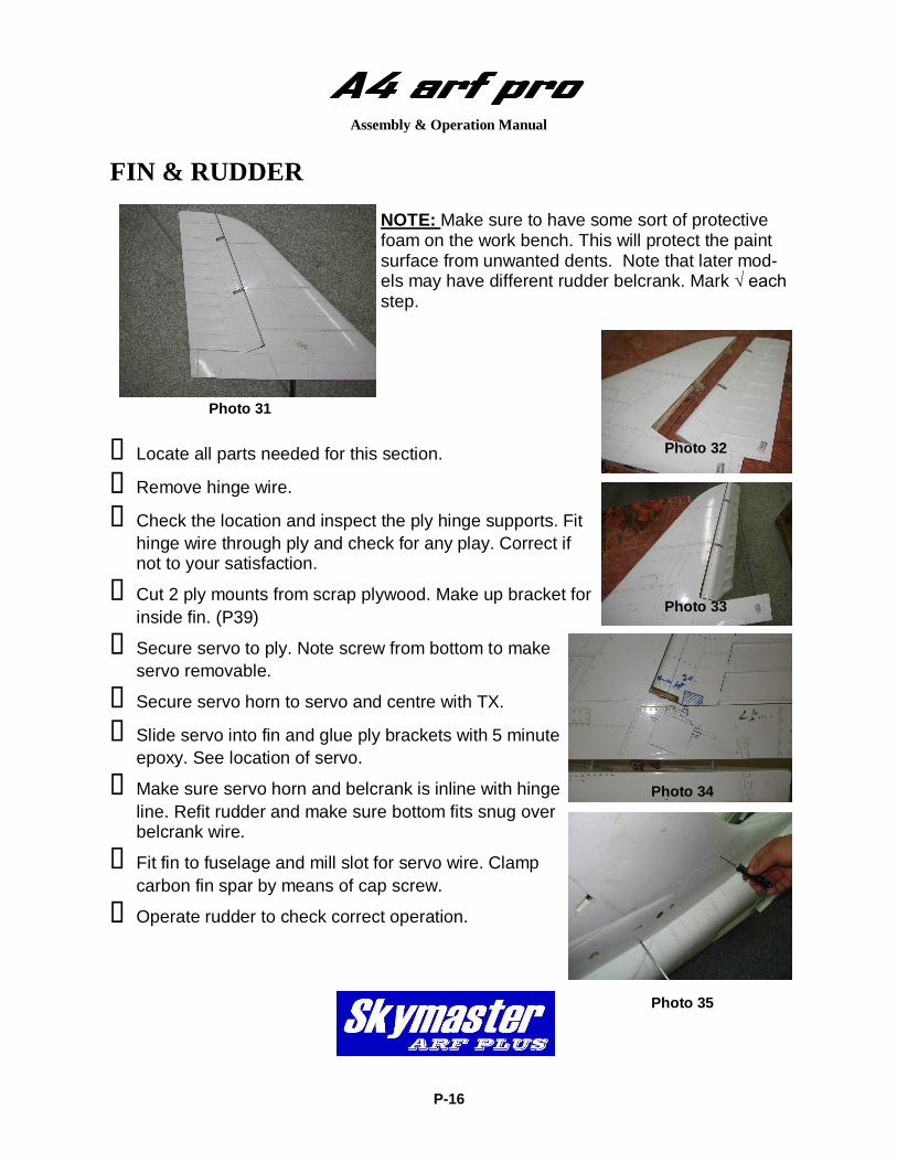
FIN & RUDDER NOTE: Make sure to have some sort of protective foam on the work bench. This will protect the paint surface from unwanted dents. Note that later mod-els may have different rudder belcrank. Mark √ each step.
Locate all parts needed for this section.
Remove hinge wire.
Check the location and inspect the ply hinge supports. Fit hinge wire through ply and check for any play. Correct if not to your satisfaction.
Cut 2 ply mounts from scrap plywood. Make up bracket for inside fin. (P39)
Secure servo to ply. Note screw from bottom to make servo removable.
Secure servo horn to servo and centre with TX.
Slide servo into fin and glue ply brackets with 5 minute epoxy. See location of servo.
Make sure servo horn and belcrank is inline with hinge line. Refit rudder and make sure bottom fits snug over belcrank wire.
Fit fin to fuselage and mill slot for servo wire. Clamp carbon fin spar by means of cap screw. Operate rudder to check correct operation.
P-16
Photo 33
Photo 34
Photo 31
Photo 32
Photo 35
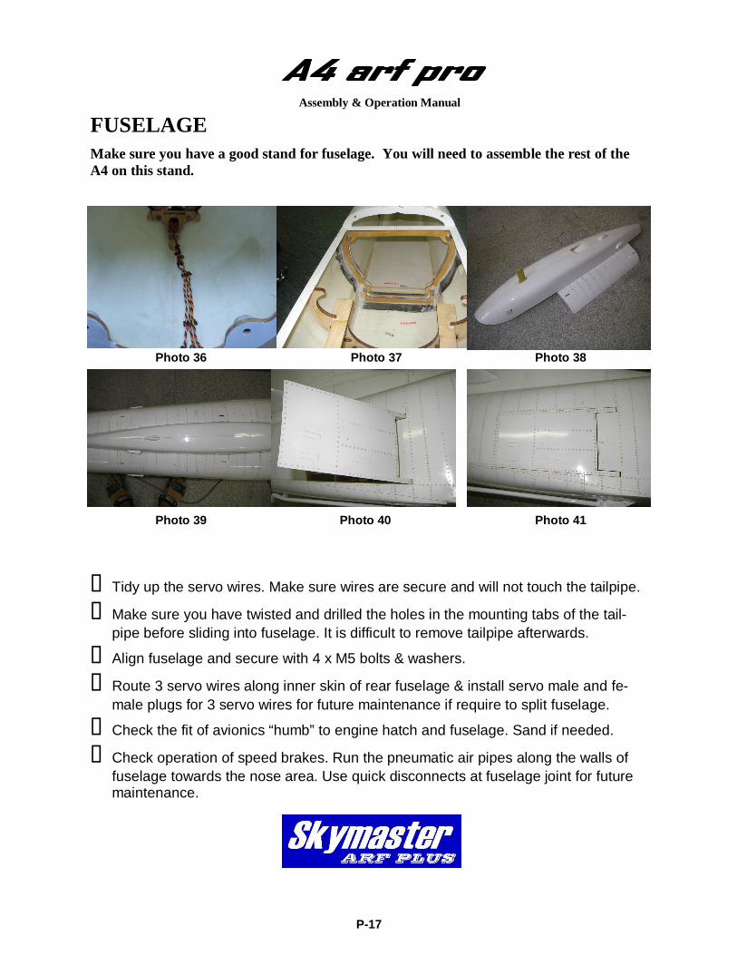
FUSELAGE
Make sure you have a good stand for fuselage. You will need to assemble the rest of the A4 on this stand.
Tidy up the servo wires. Make sure wires are secure and will not touch the tailpipe.
Make sure you have twisted and drilled the holes in the mounting tabs of the tail-pipe before sliding into fuselage. It is difficult to remove tailpipe afterwards.
Align fuselage and secure with 4 x M5 bolts & washers.
Route 3 servo wires along inner skin of rear fuselage & install servo male and fe-male plugs for 3 servo wires for future maintenance if require to split fuselage.
Check the fit of avionics “humb” to engine hatch and fuselage. Sand if needed.
Check operation of speed brakes. Run the pneumatic air pipes along the walls of fuselage towards the nose area. Use quick disconnects at fuselage joint for future maintenance.
P-17
Assembly & Operation Manual
Photo 36 Photo 37
Photo 45
Photo 38
Photo 41 Photo 39 Photo 40
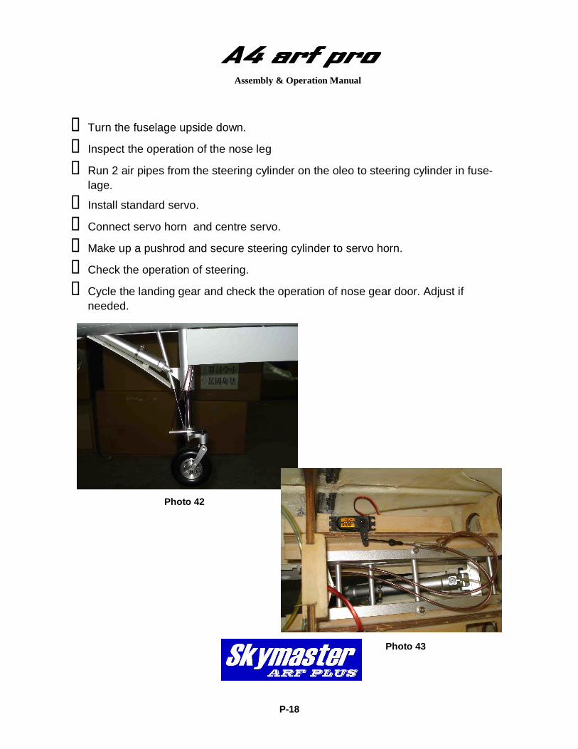
Turn the fuselage upside down.
Inspect the operation of the nose leg
Run 2 air pipes from the steering cylinder on the oleo to steering cylinder in fuse-lage.
Install standard servo.
Connect servo horn and centre servo.
Make up a pushrod and secure steering cylinder to servo horn.
Check the operation of steering.
Cycle the landing gear and check the operation of nose gear door. Adjust if needed.
P-18
Assembly & Operation Manual
Photo 42
Photo 43
Assembly & Operation Manual
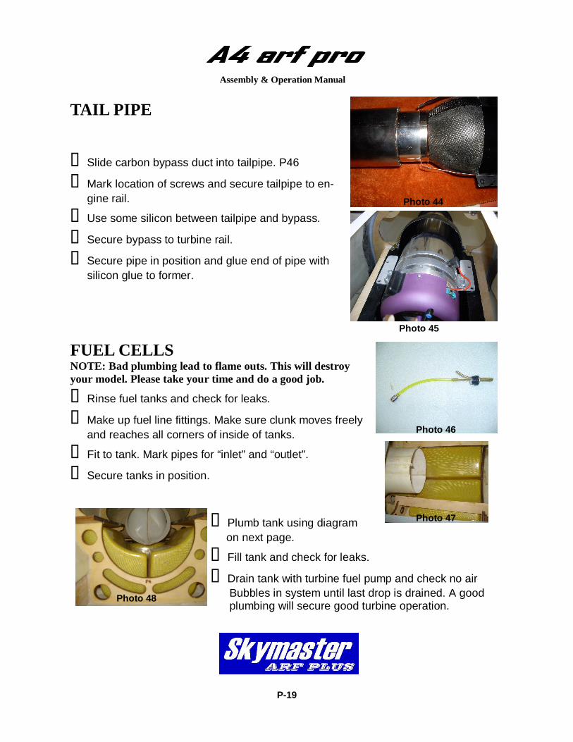
TAIL PIPE Slide carbon bypass duct into tailpipe. P46
Mark location of screws and secure tailpipe to en-gine rail.
Use some silicon between tailpipe and bypass.
Secure bypass to turbine rail.
Secure pipe in position and glue end of pipe with silicon glue to former.
Photo 44
Photo 45
FUEL CELLS NOTE: Bad plumbing lead to flame outs. This will destroy your model. Please take your time and do a good job.
Rinse fuel tanks and check for leaks.
Make up fuel line fittings. Make sure clunk moves freely and reaches all corners of inside of tanks.
Fit to tank. Mark pipes for “inlet” and “outlet”.
Secure tanks in position.
Plumb tank using diagram on next page.
Fill tank and check for leaks.
Drain tank with turbine fuel pump and check no air Bubbles in system until last drop is drained. A good plumbing will secure good turbine operation.
P-19
Photo 46
Photo 47
Photo 48
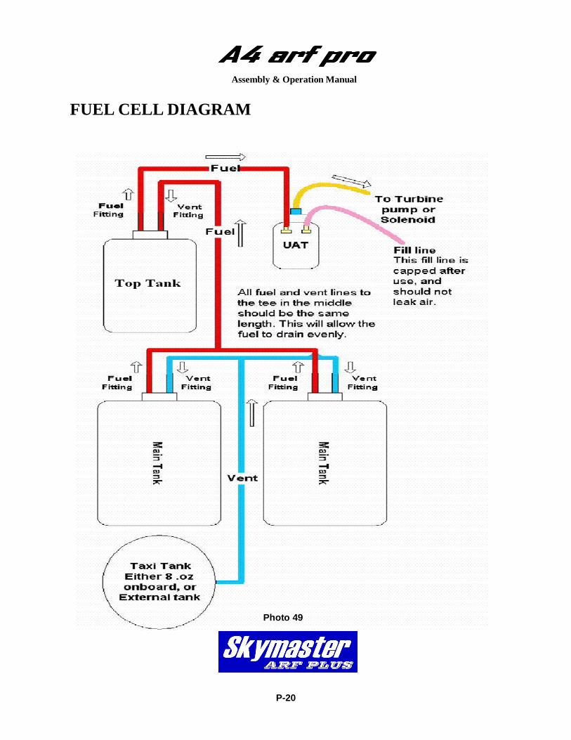
FUEL CELL DIAGRAM
P-20
Assembly & Operation Manual
Photo 49
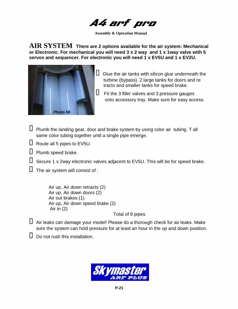
AIR SYSTEM There are 2 options available for the air system: Mechanical or Electronic. For mechanical you will need 3 x 2 way and 1 x 1way valve with 5 servos and sequencer. For electronic you will need 1 x EV5U and 1 x EV2U.
Glue the air tanks with silicon glue underneath the
turbine (bypass). 2 large tanks for doors and re tracts and smaller tanks for speed brake.
Fit the 3 filler valves and 3 pressure gauges onto accessory tray. Make sure for easy access.
Plumb the landing gear, door and brake system by using color air tubing. T all same color tubing together until a single pipe emerge.
Route all 5 pipes to EV5U. Plumb speed brake. Secure 1 x 2way electronic valves adjacent to EV5U. This will be for speed brake.
The air system will consist of : Air up, Air down retracts (2) Air up, Air down doors (2) Air out brakes (1) Air up, Air down speed brake (2) Air in (2) Total of 9 pipes
Air leaks can damage your model! Please do a thorough check for air leaks. Make sure the system can hold pressure for at least an hour in the up and down position.
Do not rush this installation.
P-21
Assembly & Operation Manual
Photo 50
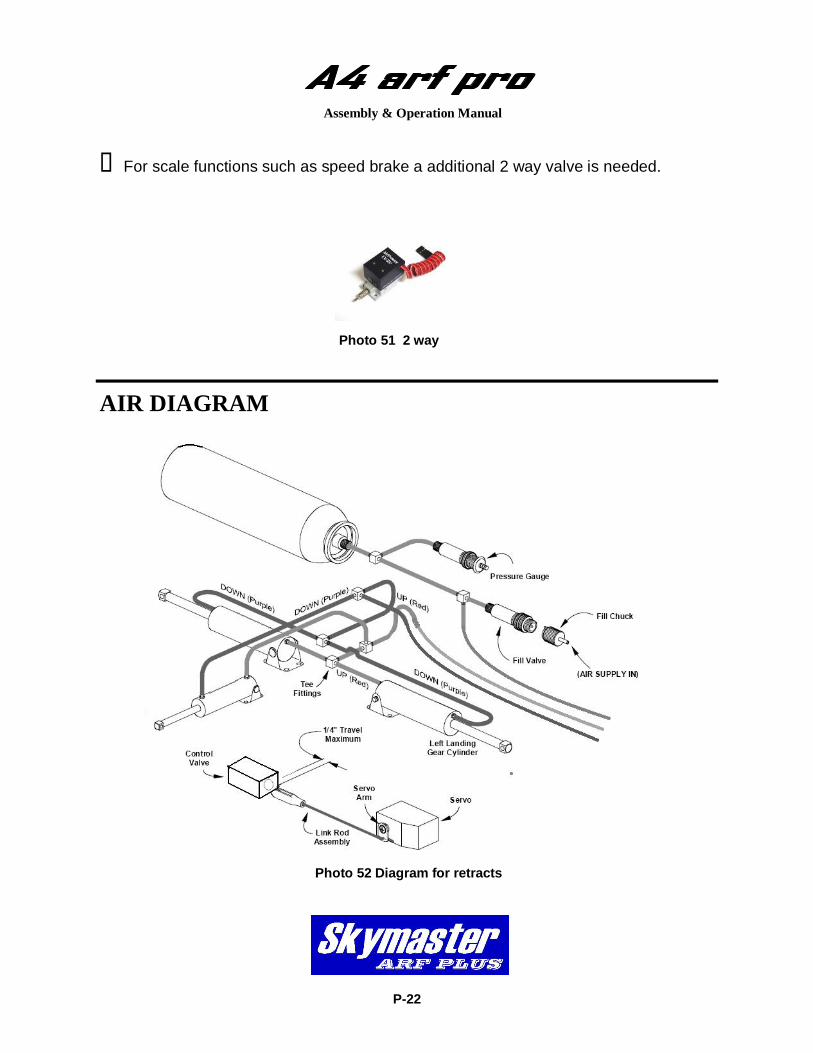
AIR DIAGRAM
P-22
Assembly & Operation Manual
Photo 52 Diagram for retracts
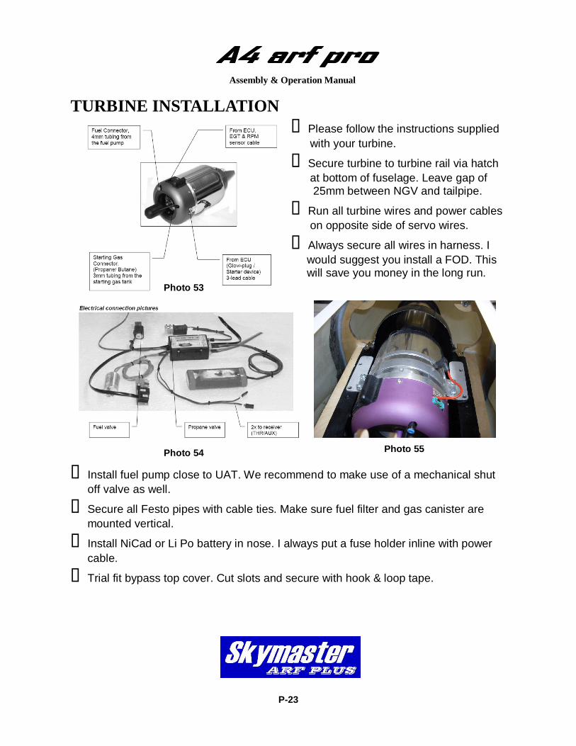
For scale functions such as speed brake a additional 2 way valve is needed.
Photo 51 2 way
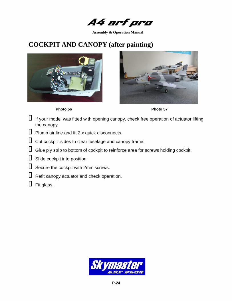
TURBINE INSTALLATION Please follow the instructions supplied
with your turbine.
Secure turbine to turbine rail via hatch at bottom of fuselage. Leave gap of 25mm between NGV and tailpipe.
Run all turbine wires and power cables on opposite side of servo wires.
Always secure all wires in harness. I would suggest you install a FOD. This will save you money in the long run.
Install fuel pump close to UAT. We recommend to make use of a mechanical shut off valve as well.
Secure all Festo pipes with cable ties. Make sure fuel filter and gas canister are mounted vertical.
Install NiCad or Li Po battery in nose. I always put a fuse holder inline with power cable.
Trial fit bypass top cover. Cut slots and secure with hook & loop tape.
P-23
Assembly & Operation Manual
Photo 53
Photo 54 Photo 55
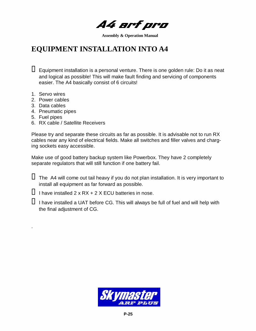
COCKPIT AND CANOPY (after painting)
P-24
Assembly & Operation Manual
If your model was fitted with opening canopy, check free operation of actuator lifting the canopy.
Plumb air line and fit 2 x quick disconnects.
Cut cockpit sides to clear fuselage and canopy frame.
Glue ply strip to bottom of cockpit to reinforce area for screws holding cockpit.
Slide cockpit into position.
Secure the cockpit with 2mm screws.
Refit canopy actuator and check operation.
Fit glass.
Photo 56 Photo 57
EQUIPMENT INSTALLATION INTO A4
P-25
Assembly & Operation Manual
Equipment installation is a personal venture. There is one golden rule: Do it as neat and logical as possible! This will make fault finding and servicing of components easier. The A4 basically consist of 6 circuits!
1. Servo wires 2. Power cables 3. Data cables 4. Pneumatic pipes 5. Fuel pipes 6. RX cable / Satellite Receivers Please try and separate these circuits as far as possible. It is advisable not to run RX cables near any kind of electrical fields. Make all switches and filler valves and charg-ing sockets easy accessible. Make use of good battery backup system like Powerbox. They have 2 completely separate regulators that will still function if one battery fail.
The A4 will come out tail heavy if you do not plan installation. It is very important to install all equipment as far forward as possible.
I have installed 2 x RX + 2 X ECU batteries in nose.
I have installed a UAT before CG. This will always be full of fuel and will help with the final adjustment of CG.
.
BEFORE YOU FLY
P-26
Assembly & Operation Manual
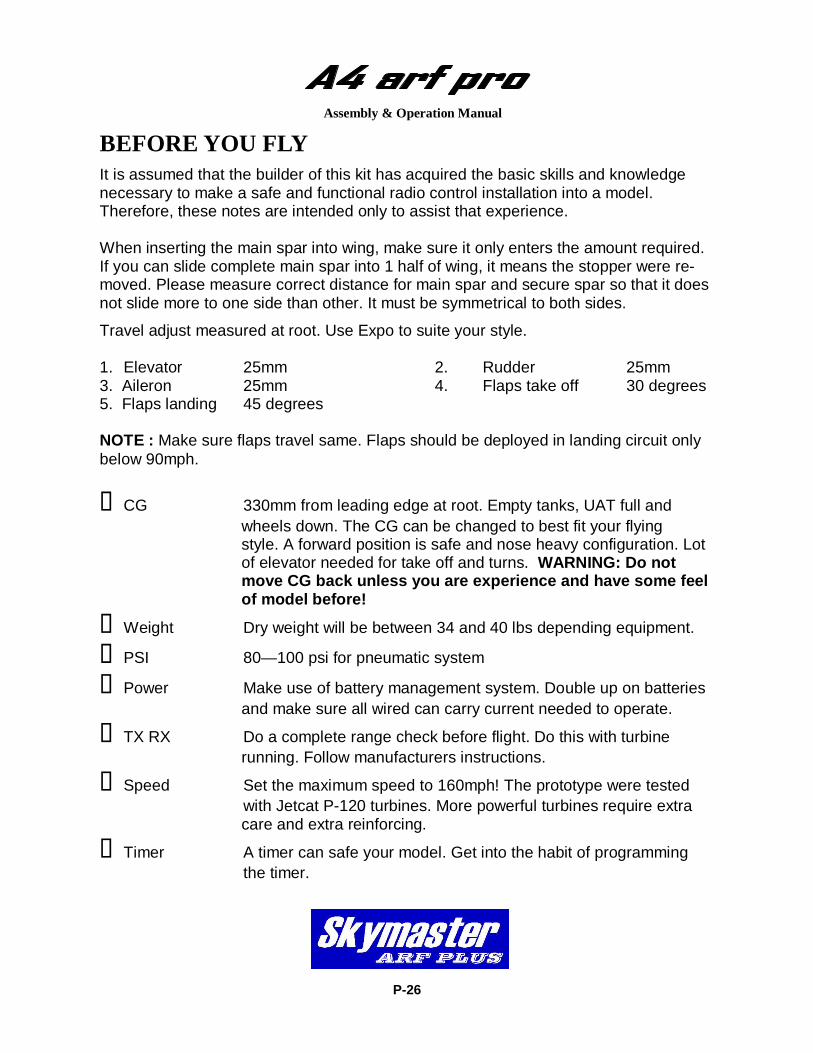
It is assumed that the builder of this kit has acquired the basic skills and knowledge necessary to make a safe and functional radio control installation into a model. Therefore, these notes are intended only to assist that experience. When inserting the main spar into wing, make sure it only enters the amount required. If you can slide complete main spar into 1 half of wing, it means the stopper were re-moved. Please measure correct distance for main spar and secure spar so that it does not slide more to one side than other. It must be symmetrical to both sides.
Travel adjust measured at root. Use Expo to suite your style. 1. Elevator 25mm 2. Rudder 25mm 3. Aileron 25mm 4. Flaps take off 30 degrees 5. Flaps landing 45 degrees NOTE : Make sure flaps travel same. Flaps should be deployed in landing circuit only below 90mph.
CG 330mm from leading edge at root. Empty tanks, UAT full and wheels down. The CG can be changed to best fit your flying style. A forward position is safe and nose heavy configuration. Lot of elevator needed for take off and turns. WARNING: Do not move CG back unless you are experience and have some feel of model before!
Weight Dry weight will be between 34 and 40 lbs depending equipment.
PSI 80—100 psi for pneumatic system
Power Make use of battery management system. Double up on batteries and make sure all wired can carry current needed to operate.
TX RX Do a complete range check before flight. Do this with turbine running. Follow manufacturers instructions.
Speed Set the maximum speed to 160mph! The prototype were tested with Jetcat P-120 turbines. More powerful turbines require extra care and extra reinforcing.
Timer A timer can safe your model. Get into the habit of programming the timer.
P-27
Assembly & Operation Manual
Take-Off Do some taxi tests before your flight! Make sure you are familiar with all settings and make sure the model track straight on the ground without rudder input. Choose a fine day for the maiden flight. Do not force a maiden flight! Select take off flap or flight mode 1 and open throttle. Gently pull back on stick 50m down the runway. Raise the flaps and gear at safe altitude and let the model sit on rails. Slow Flight Most of the first flight should be utilized to get familiar with the slow speed flight charac-teristics. Select the flaps to the takeoff position; there should be no pitch change. Ex-tend the gear and select full landing flaps; adjust the power to maintain level flight and a speed of about 80—90mph. Climb to a safe altitude and slow the model to the edge of a stall to know where that edge is. Landing Fly a complete circuit before landing. Approach from the downwind side and lower the LG. Fly a complete circuit getting use to the power required. On the next circuit lower the flaps. If you have a headwind be very careful not to get below the power curve on the downwind side. Do not use speed brakes for landing on maiden. The A4 is a semi delta wing. So any pull on the elevator will bleed of speed very quickly. Keep a nose high approach and control the sink rate with good throttle management. Align the model by means of rudder and use throttle to control the descent! Flare the model just before touch down. Let the model roll out and apply brakes. Taxi back and do necessary adjustments to customize A4 for your need! We at Skymaster wish you many happy flights with your Skyhawk! Add some more scale options like drop tanks etc. Before and after landing open canopy for extra real-ism. Add landing lights and smoke system and your A4 will be just like real thing. Anton Lin and Skymaster Team!
OPTIONAL SCALE PARTS
P-27
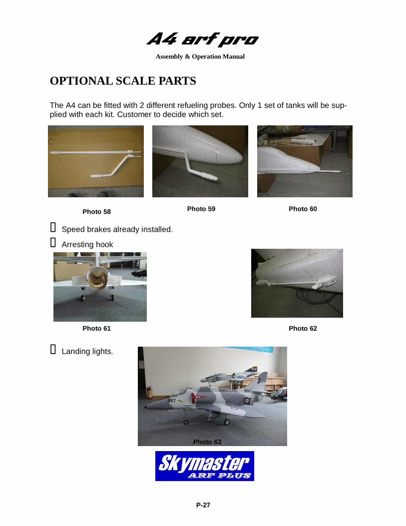
The A4 can be fitted with 2 different refueling probes. Only 1 set of tanks will be sup-plied with each kit. Customer to decide which set.
Speed brakes already installed.
Arresting hook
Landing lights.
Photo 58
Assembly & Operation Manual
Photo 59
Photo 61 Photo 62
Photo 63
Photo 60