Embed Size (px)
Citation preview
150W Inverter - an optimal
Presenter: Dr Gawie van der Merwe
design in solar home
systems.
Copyright DR Gawie van der Merwe www.planmypower.co.zaa
Background
Complete “Solar Home” kits are being presented as an option to power remote areas
Kit typically consists of– 1 or 2 solar panels– Small PV regulator– Suited DC or AC Lights– Small 50Hz inverter– Battery and suitable enclosure
Cost and reliability of some of above components are problems
Investigation was done on the optimal design of an inverter to comply with solar home requirements
Copyright DR Gawie van der Merwe www.planmypower.co.zaa
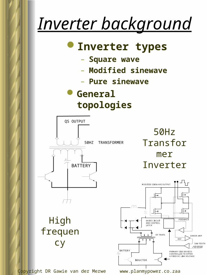
Inverter backgroundInverter types
– Square wave– Modified sinewave– Pure sinewave
General topologies
SAWTOOTH
HF TRAFO
INDUCTOR
BATTERY
ERROR AMP
FEEDBACKDRIVE CIRCUITAND CONTROLLATCH
PRIMARY SIDE DEVICESCONTROLLED TO OFFERA FIXED DC LINK VOLTAGE
MODIFIED SINEWAVE OUTPUT
REF
50Hz Transformer
Inverter
High frequency
BATTERY
QS OUTPUT
50HZ TRANSFORMER
Copyright DR Gawie van der Merwe www.planmypower.co.zaa
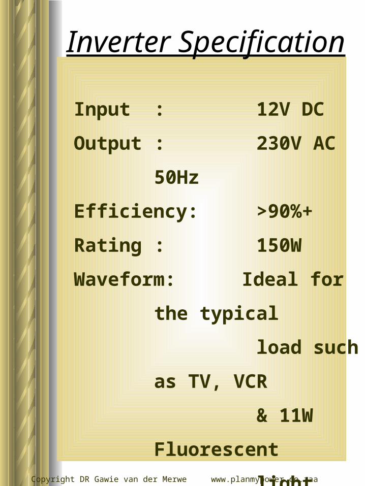
Input : 12V DC
Output : 230V AC
50Hz
Efficiency: >90%+
Rating : 150W
Waveform: Ideal for the
typical
load such as
TV, VCR
& 11W
Fluorescent
light
Cost : As low as
possible
MTBF : >10 year
Inverter Specification
Copyright DR Gawie van der Merwe www.planmypower.co.zaa
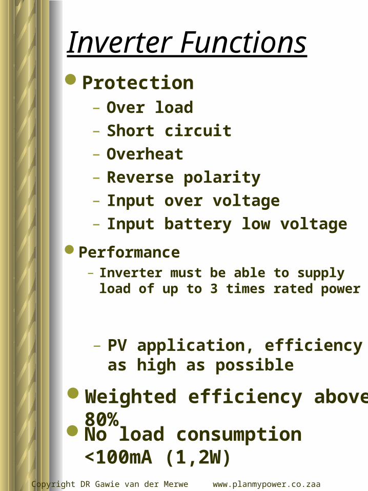
Inverter FunctionsProtection
– Over load– Short circuit– Overheat– Reverse polarity– Input over voltage– Input battery low voltage
– PV application, efficiency as high as possible
No load consumption <100mA (1,2W)
Performance– Inverter must be able to supply
load of up to 3 times rated power
Weighted efficiency above 80%
Copyright DR Gawie van der Merwe www.planmypower.co.zaa
Research
Industrial inverters
disseminated
Various loads analysed
Conditions of operation
investigated
Production complexity and
cost investigated
Copyright DR Gawie van der Merwe www.planmypower.co.zaa
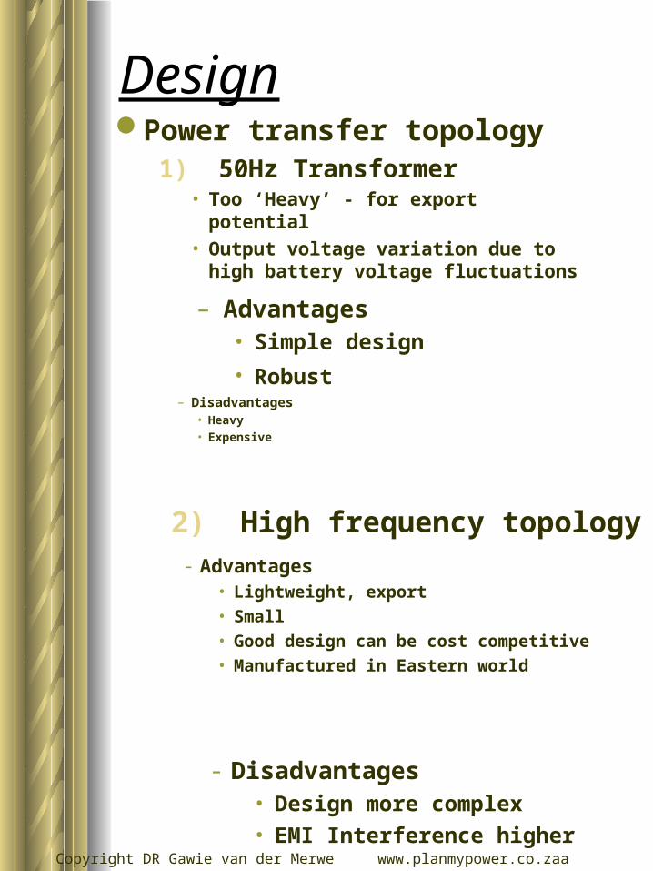
– Disadvantages• Heavy
• Expensive
DesignPower transfer topology
1) 50Hz Transformer• Too ‘Heavy’ - for export potential
• Output voltage variation due to high battery voltage fluctuations
– Advantages• Simple design
• Robust
2) High frequency topology- Advantages
• Lightweight, export• Small• Good design can be cost competitive• Manufactured in Eastern world
- Disadvantages• Design more complex• EMI Interference higher
Copyright DR Gawie van der Merwe www.planmypower.co.zaa
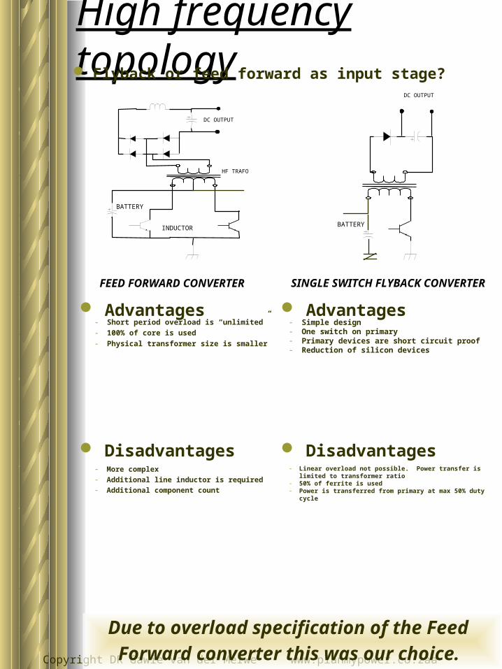
SINGLE SWITCH FLYBACK CONVERTER
High frequency topology Flyback or feed forward as input stage?
FEED FORWARD CONVERTER
HF TRAFO
INDUCTOR
BATTERY
DC OUTPUT
DC OUTPUT
BATTERY
- Simple design- One switch on primary- Primary devices are short circuit proof- Reduction of silicon devices
Advantages
Disadvantages- Linear overload not possible. Power transfer is limited
to transformer ratio- 50% of ferrite is used- Power is transferred from primary at max 50% duty cycle
Advantages- Short period overload is “unlimited”- 100% of core is used- Physical transformer size is smaller
Disadvantages- More complex- Additional line inductor is required- Additional component count
Due to overload specification of the Feed
Forward converter this was our choice.
Copyright DR Gawie van der Merwe www.planmypower.co.zaa
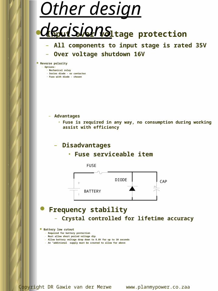
Input over voltage protection– All components to input stage is rated 35V– Over voltage shutdown 16V
Reverse polarity– Options:
• Mechanical relay• Series diode - or contactor• Fuse with diode - chosen
– Advantages• Fuse is required in any way, no consumption during working assist with
efficiency
– Disadvantages• Fuse serviceable item
Frequency stability– Crystal controlled for lifetime accuracy
FUSE
DIODE
BATTERY
CAP
Battery low cutout– Required for battery protection
– Must allow short period voltage dip
– Allow battery voltage drop down to 8.8V for up to 10 seconds
– An “additional” supply must be created to allow for above
Other design decisions
Copyright DR Gawie van der Merwe www.planmypower.co.zaa
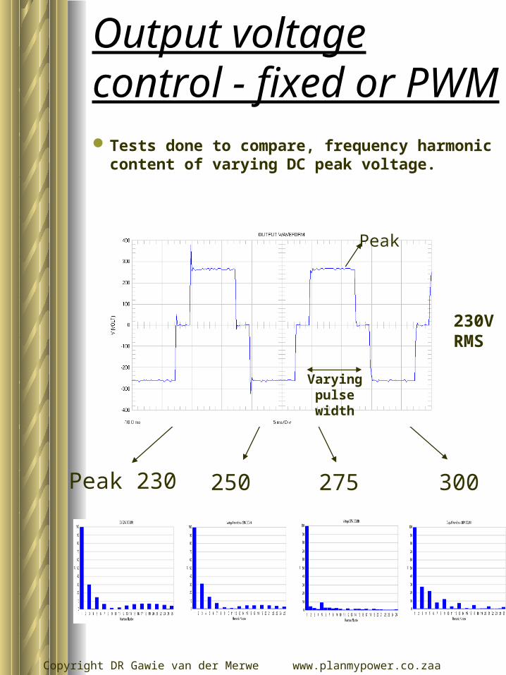
Tests done to compare, frequency harmonic content of varying DC peak voltage.
Peak 230 300250 275
Peak
230V RMS
Varying pulse width
Output voltage control - fixed or PWM

Copyright DR Gawie van der Merwe www.planmypower.co.zaa
Fixed duty cycle
Fixed DC link voltage
V DC = 265V - 60-70% duty cycle found to be best under general conditions.
(refer to other load tests)
Decision
Copyright DR Gawie van der Merwe www.planmypower.co.zaa
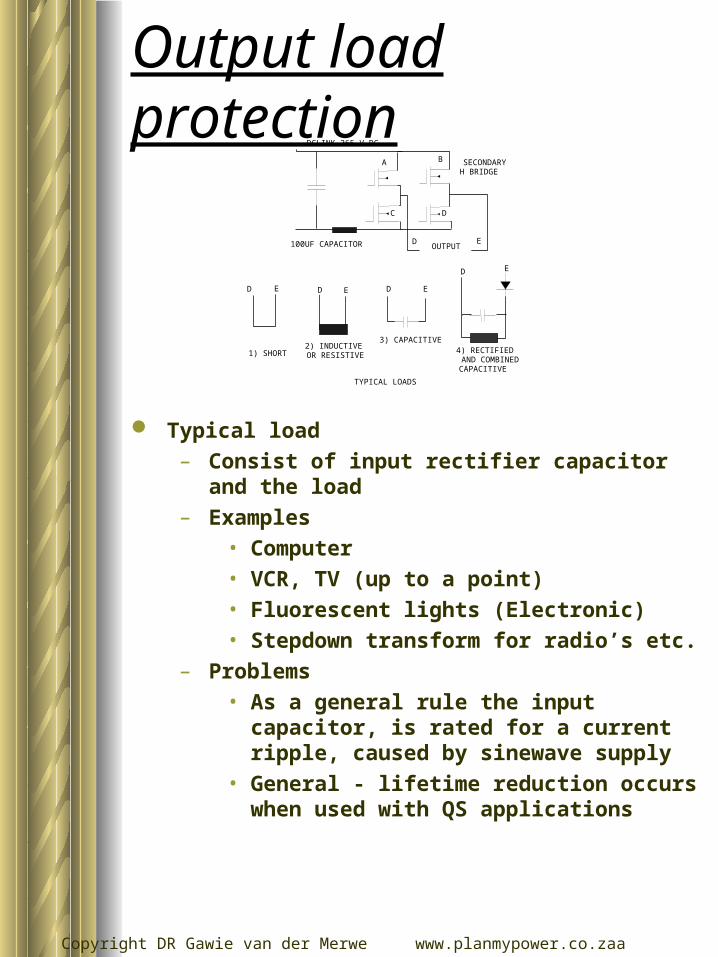
SECONDARYH BRIDGE
OUTPUT
A B
C D
D E
TYPICAL LOADS
2) INDUCTIVEOR RESISTIVE1) SHORT
3) CAPACITIVE4) RECTIFIEDAND COMBINEDCAPACITIVE
D D DE E E
D E
DCLINK 265 V DC
100UF CAPACITOR
Typical load– Consist of input rectifier capacitor and the load– Examples
• Computer• VCR, TV (up to a point)• Fluorescent lights (Electronic)• Stepdown transform for radio’s etc.
– Problems• As a general rule the input capacitor, is rated
for a current ripple, caused by sinewave supply
• General - lifetime reduction occurs when used with QS applications
Output load protection
Copyright DR Gawie van der Merwe www.planmypower.co.zaa
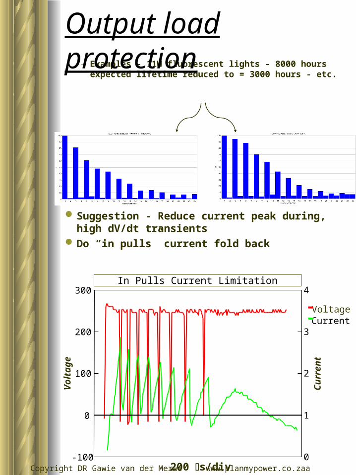
– Examples - 11W fluorescent lights - 8000 hours expected lifetime reduced to = 3000 hours - etc.
Suggestion - Reduce current peak during, high dV/dt transients
Do “in pulls” current fold back
VoltageCurrent
Output load protectionV
olt
age
In Pulls Current Limitation
-100
0
100
200
300
0
1
2
3
4
Cu
rren
t
200 s/div

Copyright DR Gawie van der Merwe www.planmypower.co.zaa
Rating 150W
– Non linear loads or loads with a low Power Factor not very “measurable”
– 3 methods of overload protection
• AC output current measure
• AC current peak measure
• Primary side DC current measurement - Input power
Overload protection
Copyright DR Gawie van der Merwe www.planmypower.co.zaa
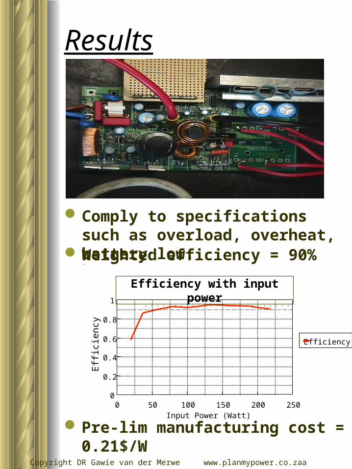
Results
Comply to specifications such as overload, overheat, battery low.
Weighted efficiency = 90%
Pre-lim manufacturing cost = 0.21$/W
0 50 100 150 200 2500
0.2
0.4
0.6
0.8
1
Input Power (Watt)
Eff
icie
ncy
Efficiency with input power
Efficiency
Copyright DR Gawie van der Merwe www.planmypower.co.zaa
Conclusion & further work
A well designed inverter, with
all requirement
First production stage
undergone
Load life time test still being
done with items such as small
fluorescent light.
Inverter lifetime test still to be
done!