Embed Size (px)
Citation preview
Español English
DINFLEX /1ASensor flexible de corriente/
Flexible current sensor
PRODUCT
The DINFLEX /1A allow to connect a conventional electrical network analyzer to a flex clamp with built in electronic (series TLE). The system is composed of three main parts: flex clamp, Dinflex /1A and electrical network analyzer. The Dinflex /1A provides power to the clamps and allow simultaneous range scaling of the same, finally connects with its output current signals measured by the clamps (/1A) to the analyzer.
The non-intrusive flexible current sensor provides the ability to measure alternating current in any installation with a full rejection of DC component, very low consumption, no saturation problem, very low temperature dependence, very good linearity.
Thanks to the flexibilty of these current transducers, one or diverse conductors can be embraced, regardless their shape (insulated cables, tubes, etc.), To execute current measuring actions.
Measurement uncertainly assumes centralized primary conductor at optimun position, no external electric or magnetic field, and within operating temperature range
SAFETY PRECAUTIONSThe DINFLEX /1A has been designed and tested to fulfil the safety standard IEC 61010-1:2001/EN 61010-1 61010-2-32:2002
Prior to use the DINFLEX /1A for the first time, read the following carefully:
1. The DINFLEX /1A must be only used by qualifiedpersonal.
2. Use of the probe on uninsulated conductors islimited to 600VACrms or DC to frequencies below1KHz.
3. Do not expose the DINFLEX /1A to aggressive orexplosive environment.
4. Do not use the DINFLEX /1A if there any reason tothink that its no operating properly or that it is faulty.
5. For measuring in uninsolated conductor use theappropriate and necessary personal protectionequipment.
PRODUCTO
El DINFLEX /1A permite conectar a un analizador de redes eléctricas, 1 pinza flexible con electrónica incorporada (serie TLE). El equipo esta formado por tres partes principales: pinza flexible, dinflex /1A yl analizador de redes eléctricas. La Dinflex /1A proporciona alimentación a las pinzas y permite el cambio de escalas simultáneo de las mismas, finalmente mediante sus salidas permite conectar las señales de corriente medidas (/1A) por las pinzas al analizador.
El sensor flexible de corriente permite realizar mediciones de corriente alterna en cualquier instalación con total rechazo de componentes DC, muy bajo consumo de potencia y muy buena linealidad.
Gracias a la flexibilidad del sensor de corriente, es posible rodear uno o varios conductores sin tener en cuenta su forma, para ejecutar acciones de medida de corriente.
La incertidumbre en la medida se considera con el sensor en la posición óptima sin campos eléctricos ni magnéticos externos y dentro del rango de temperatura de trabajo.
PRECAUCIONES DE SEGURIDADEl DINFLEX /1A ha sido diseñado y probado para cumplir el estándar de seguridad IEC 61010-1:2001/ EN 61010-1 61010-2-32:2002.
Antes de utilizar el DINFLEX /1A por primera vez, lea cuidadosamente lo siguiente:
1. El DINFLEX /1A d ebe ser utilizado por personalcualificado.
2. El uso de la sonda en conductores no aislados estalimitado a 600VACrms o DC a frecuencias pordebajo de 1KHz.
3. No exponga DINFLEX /1A a ambientes agresivos oexplosivos.
4. No utilice DINFLEX /1A si tiene alguna razón parapensar que su funcionamiento no es correcto o quees defectuoso.
5. Para medidas sobre conductores no aislados utiliceel equipo de protección personal apropiado ynecesario.
EXTERNAL CONNECTIONS
1. 24VDC power supplied.2.You can connect a flex clamp wich consist of 4 wires
each: 5V DC power supply (White), GND (Gray),range selector (Yellow) and the output signal(Green).
3.The device has one output to current signalsmeasured by the sensor and its delivery to theanalyzer (/1A).
USING THE CURRENT SENSOR
1. Before using the current flex sensor ensure that theconditions are the appropiates for working, and thatthe protection equipment is the adequate.
2. Ensure that the wires connection are properlyconfigured.
3. Disengage the snap connector and surround theconductor to measure.
4. Close the snap connector ensuring their anchorage.5. Put the conductor centred within the sensor.
MAINTENANCE:The current flex sensor do not require a special maintenance.
CONEXIONES EXTERNAS
1. Requiere alimentación 24VDC.2. Se pueden conectar pinzas las cuales constan de 4
cables cada una: alimentación 5V DC (Blanco),GND (Gris), selector de escala (Amarillo) y la señalde salida (Verde).
3.El equipo cuenta con una salida para obtener lasseñales de corriente medidas por el sensor y suposterior envío al analizador (/1A).
USO DEL SENSOR DE CORRIENTE
1. Antes de usar el sensor de corriente, asegurarseque las condiciones son las apropiadas paratrabajar y que el equipo de protección es eladecuado.
2. Asegurese que los cables de conexión estáncorrectamente configurados.
3. Desenganche el conector y rodee con la sonda elcable a medir.
4. Cierre el conector asegurándose de su anclaje.5. Posicione el conductor centrado en relación al
sensor.
MANTENIMIENTOEl sensor de corriente no requiere un mantenimiento especial.
SÍMBOLOS / SYMBOLS
Atención! Revisar el manual/Attention! Refer to manual
Doble aislamiento/Double Isolation
Rango de Temperatura:Temperatura de
Almacenamiento:Protección IP:
Dimensiones (LxWxH):
-25 °C to 70 °C
-40 °C to 85 °C IP2090x67x104 (mm)
CARACTERÍSTICAS FÍSICAS YAMBIENTALES DINFLEX-3P/
PHYSICAL AND ENVIRONMENT FEATURES DINFLEX /1A
Temperature Range:Storage Temperature:
Protection IP:Size (LxWxH):
-25 °C to 70 °C -40 °C to 85 °C IP2090x67x104 (mm)
Material Sonda/Probe Material
Material de Acoples/Couplings Material
Diámetro Cable Sonda/Probe Cable Diameter
Longitud Cable Salida/Output Cable lenght
Rango Temperatura/Temperature Range
Temperatura deAlmacenamiento
/Storage Temperature
Humedad Relativa/Relative Humidity
Protección IP/Protection IP
Autoextinguible/Self-extinguishable
UNE 21031 90°C
PA V-0
14mm
2m
-20 °C a 85 °C
-40 °C a 85 °C
15% to 85%(sin condensación)
/without condensing)
IP54
S54 S14 / S25
CARACTERÍSTICAS FÍSICAS YAMBIENTALES SENSOR/
PHYSICAL AND ENVIRONMENT FEATURES CLAMPS
Autoextinguible/Self-extinguishable
UNE 21031 90°C
PA V-0
8mm
2m
-20 °C a 85 °C
-40 °C a 85 °C
15% to 85%(sin condensación)
/without condensing)
IP54
Din-Flex /1A
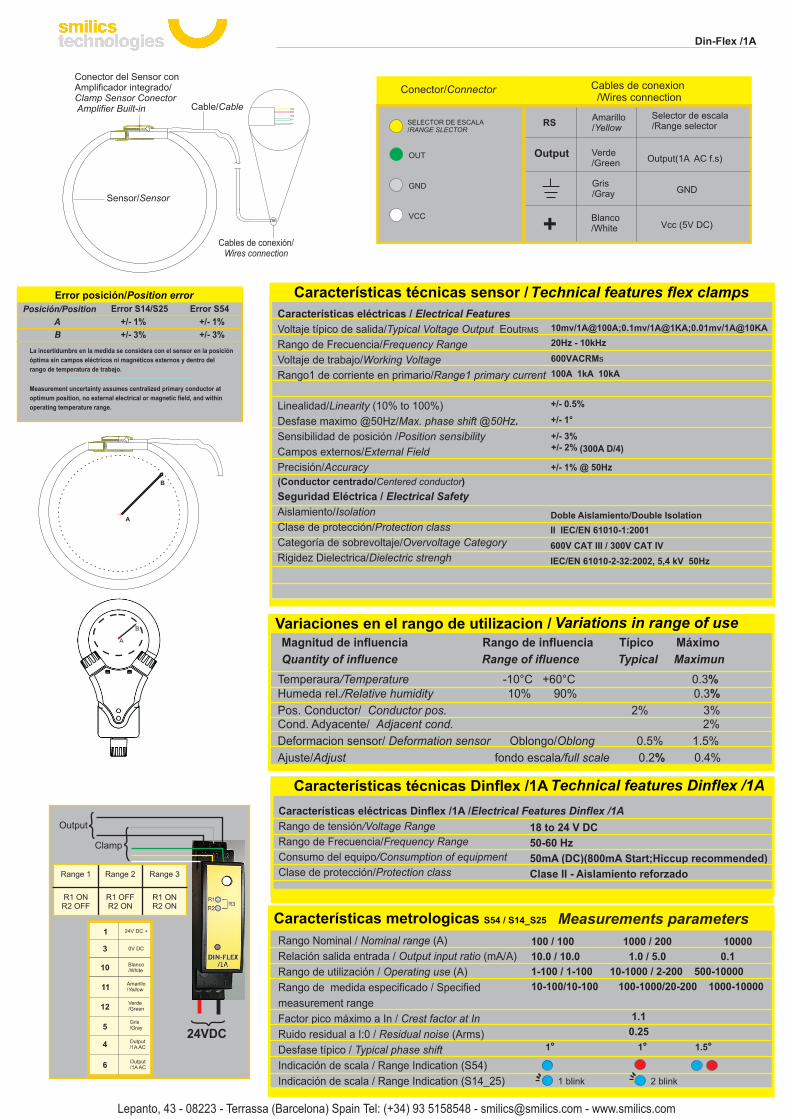
Sensor/Sensor
Cables de conexión/Wires connection
Conector del Sensor conAmplificador integrado/Clamp Sensor Conector Amplifier Built-in Cable/Cable
Características eléctricas Dinflex /1A /Electrical Features Dinflex /1A
Rango de tensión/Voltage Range
Rango de Frecuencia/Frequency Range
Consumo del equipo/Consumption of equipment
Clase de protección/Protection class
18 to 24 V DC
50-60 Hz
50mA (DC)(800mA Start;Hiccup recommended)
Clase II - Aislamiento reforzado
Características técnicas / Technical featuresCaracterísticas técnicas Dinflex /1A Technical features Dinflex /1A
Características eléctricas / Electrical Features
Voltaje típico de salida/Typical Voltage Output EoutRMS
Rango de Frecuencia/Frequency Range
Voltaje de trabajo/Working Voltage
Rango1 de corriente en primario/Range1 primary current
Linealidad/Linearity (10% to 100%)
Desfase maximo @50Hz/Max. phase shift @50Hz.
Sensibilidad de posición /Position sensibility
Campos externos/External Field
Precisión/Accuracy
(Conductor centrado/Centered conductor)
Seguridad Eléctrica / Electrical Safety
Aislamiento/Isolation
Clase de protección/Protection class
Categoría de sobrevoltaje/Overvoltage Category
Rigidez Dielectrica/Dielectric strengh
10mv/1A@100A;0.1mv/1A@1KA;0.01mv/1A@10KA
20Hz - 10kHz
600VACRMs
100A 1kA 10kA
+/- 0.5%
+/- 1°
+/- 3%+/- 2% (300A D/4)
+/- 1% @ 50Hz
Características técnicas sensor / Technical features flex clamps
Doble Aislamiento/Double IsolationII IEC/EN 61010-1:2001
600V CAT III / 300V CAT IV
IEC/EN 61010-2-32:2002, 5,4 kV 50Hz
Posición/Position
A
B
Error S14/S25 Error S54
+/- 1% +/- 1%
+/- 3% +/- 3%
Error posición/Position error
La incertidumbre en la medida se considera con el sensor en la posición
óptima sin campos eléctricos ni magnéticos externos y dentro del
rango de temperatura de trabajo.
Measurement uncertainty assumes centralized primary conductor at
optimum position, no external electrical or magnetic field, and within
operating temperature range.
A
B
B
A Magnitud de influencia Rango de influencia Típico Máximo
Quantity of influence Range of ifluence Typical Maximun
Características técnicas / Technical featuresVariaciones en el rango de utilizacion / Variations in range of use
Temperaura/Temperature -10°C +60°C 0.3%Humeda rel./Relative humidity 10% 90% 0.3%
Pos. Conductor/ Conductor pos. 2% 3% Cond. Adyacente/ Adjacent cond. 2%
Deformacion sensor/ Deformation sensor Oblongo/Oblong 0.5% 1.5%
Ajuste/Adjust fondo escala/full scale 0.2% 0.4%
OUT
VCC
GND
SELECTOR DE ESCALA/RANGE SLECTOR
Conector/Connector Cables de conexion /Wires connection
Amarillo/Yellow
Selector de escala/Range selector
Verde/Green Output(1A AC f.s)
Output
Gris/Gray GND
Blanco/White Vcc (5V DC)
RS
24VDC
Clamp
Output
Rango Nominal / Nominal range (A)
Relación salida entrada / Output input ratio (mA/A)
Rango de utilización / Operating use (A)
Rango de medida especificado / Specified
measurement range
Factor pico máximo a In / Crest factor at In
Ruido residual a I:0 / Residual noise (Arms)
Desfase típico / Typical phase shift
Indicación de scala / Range Indication (S54)
Indicación de scala / Range Indication (S14_25)
100 / 100 1000 / 200 10000
10.0 / 10.0 1.0 / 5.0 0.1
1-100 / 1-100 10-1000 / 2-200 500-10000
10-100/10-100 100-1000/20-200 1000-10000
1.1
0.25
1 ° 1° 1.5°
Características metrologicas S54 / S14_S25 Measurements parameters
Din-Flex /1A
1 blink 2 blink
12
11
1
3
Amarillo/Yellow
Verde/Green
Gris/Gray
Blanco/White
24V DC +
0V DC
10
5
4
6
Output/1A AC
Output/1A AC
Range 1 Range 2 Range 3
R1 ONR2 OFF
R1 OFFR2 ON
R1 ONR2 ON
Lepanto, 43 - 08223 - Terrassa (Barcelona) Spain Tel: (+34) 93 5158548 - [email protected] - www.smilics.com


![Teoria de Sensores de Deformacion ( Celdas de Carga)[1]](https://img.pdfslide.us/doc/110x75/55cf900d550346703ba2c020/teoria-de-sensores-de-deformacion-celdas-de-carga1.jpg)