Embed Size (px)
Citation preview

15.01 GENERAL HVAC (6-01)
DESIGN CRITERIA/FACILITY STANDARDS MANUAL 248
PART ONE I. General
Because only a small portion of HVAC design is code-driven, and because the choice of HVAC design concepts bears heavily on maintenance cost and energy cost, the University has certain preferences, and expects to see them reflected in designs submitted our consultants. By not doing so, the designer risks rejection of the concept and a requirement to rework without additional compensation.
The intent of this document is not to dictate the design concept but the interplay of first cost, performance, maintenance and operating cost related to the mechanical systems remains the responsibility of the designer. If the University’s preferences are at variance with the application in design, the onus is on the designer to bring this to the attention of the University.
Neither is it the intent to discourage creativity. Alternatives are welcome. In fact, depending on the circumstances of project funding, State regulations may require life cycle analysis of several alternatives for HVAC systems. When such comparative analysis is required, the concepts, systems, and components described herein by those favored by the University must be among the alternatives analyzed.
Unless specifically directed otherwise by the program document, the following HVAC standards and preferred design concepts apply to all projects on the College Park campus of the University of Maryland.
A. Design Conditions - Heating and Cooling
Perform the HVAC load calculations based on the following outside conditions
Summer -95 degrees design drybulb,78 degrees wet bulb Winter - 0 degrees drybulb (colder than the ASHRAE 99% value)
Select cooling towers at 78 degree design wet bulb (the ASHRAE 1% value)
15.01 GENERAL HVAC (6-01)
DESIGN CRITERIA/FACILITY STANDARDS MANUAL 249
Design for the following Inside conditions:
Summer 74 degrees drybulb +/-2 degrees (Operating range of 72-76) Winter 70 degrees drybulb +/-2 degrees (Operating range of 68 - 72)
B. Humidity control
1. Summer: Unless noted to the contrary in the
program document, inside relative humidity is not to be directly controlled - the University recognizes that dehumidification is a byproduct of the cooling process. However, it is required that cooling equipment and systems be selected and sized to produce 50% rh + / - 5% in the conditioned space when design outside conditions prevail , and other design parameters are fulfilled.
HVAC system concepts noted for poor humidity control at part load conditions are subject to rejection. Such systems include, but are not limited to:
a. Systems which allow outside (ventilation) air to pass over inactive cooling coil surfaces.
b. Capacity control schemes which allow coil temperatures to rise above that required for dehumidification.
c. Systems which do not continuously dehumidify all ventilation (outside) air.
2. Winter: The university standard is to add no
moisture to the air stream. When the program document indicates that humidity control in winter is required, it is expected that humidification equipment will be sized with respect to the envelopes ability to accommodate elevated levels of interior air dewpoint.
Conditions that result in condensation on inside surfaces, visible or concealed must be avoided. The University’s intent is to avoid microbial growth on interior surfaces. (see Equipment humidification).
15.01 GENERAL HVAC (6-01)
DESIGN CRITERIA/FACILITY STANDARDS MANUAL 250
C. Ventilation
1. CFM/person is the university standard for
quantification of ventilation rates.
Population density will be defined in the program document. Otherwise, refer to ASHRAE Standard 62. Reasonable assumptions (diversity, etc) are encouraged in determining the population for purposes of determining the ventilation air quantity, but the assumptions must be documented and understood by the Using agency.
2. Unless the specific application or the applicable
building code mandates higher ventilation air quantities, HVAC designers must respect the most current revision of ASHRAE standard 62, while pursuing reasonable first cost, energy-efficient HVAC design noted in ASRAE 90.1-1999 (or most recent edition). Where aspects of energy use and air quality are in conflict, air quality shall take precedence.
3. Note: In attempts to use ASHRAE standard 62
interpretations to reduce the volume of ventilation air, it will not always be possible to assume scenarios of continuous ventilation, non-continuous occupancy. A representative of the Using agency must agree to the occupancy scenarios.
4. The application of CO2 sensors is encouraged where
appropriate to minimize cooling, dehumidification, and heating of outside ventilation air.
D. Duct liner
Acoustical (fiberglass) duct liner is preferred as the economical alternative to oversized ducts (low velocities) and mechanical sound control devices. However, the duct liner product, and the application techniques, must be specified with the intent to avoid IAQ problems. Examples include, but are not limited to:
a. Special coatings to eliminate the erosion of liner
particles
b. Special Installation practices (buttered edges,
15.01 GENERAL HVAC (6-01)
DESIGN CRITERIA/FACILITY STANDARDS MANUAL 251
etc.) to deter erosion of particles
c. No liner may be used in areas where the liner may become wetted during normal system operation, or in abnormal weather conditions.
d. Locate adequately sized and spaced access openings
in duct to facilitate periodic inspection and cleaning
E. Equipment redundancy, spare capacity and back-up power
a. Redundancy - Generally, because of cost control,
redundancy is mandated only in the case of critical systems and/or equipment, identified as critical in the program document.
Regardless of the system redundancy requirements of the program document, the design shall provide for redundancy in the following items of mechanical equipment, if such equipment is a part of the project design and if the need for redundancy has not been expressly waived by the program document :
1. Condensate (steam) return units: Duplex pumps
with automatic alternators are required. The design shall be such that design flows will be handled by a single pump with 33% run time.
This equipment shall be powered from the emergency generator, if an emergency generator is part of the project. It is not the intent of this provision to create a requirement for an emergency generator.
2. Package sump pumps (storm water): The design
shall incorporate duplex pumping with automatic alternators. The design shall be such that design flows will be handled by a single pump with 33% run time.
This equipment shall be powered from the emergency generator, if an emergency generator is part of the project. It is not the intent of this provision to create a requirement for an emergency generator.
The equipment covered by this provision does
15.01 GENERAL HVAC (6-01)
DESIGN CRITERIA/FACILITY STANDARDS MANUAL 252
not refer to residential-type submersible pumps, powered from 120 VAC receptacles.
3. Sewage Ejectors - A single sump is
acceptable. Incorporate duplex pumping with automatic alternators. The design shall be such that design flows will be handled by a single pump, with 33% run time.
This equipment shall be powered from the emergency generator, if an emergency generator is part of the project. It is not the intent of this provision to create a requirement for an emergency generator.
4. Submersible sump pumps in elevator pits, etc.
There is no requirement for redundant pumps. However, a high water alarm shall be installed, connected to the CCMS, and the submersible pump shall be powered from the emergency generator, if an emergency generator is part of the project. It is not the intent of this provision to create a requirement for an emergency generator. Submersible pumps shall not be used in “pits” where exposed to temperatures above 100 degrees F. (See Division 14.01)
5. Chilled water pumps - In single chiller
applications, a second, full sized pump/motor assembly shall be designed. The second pump shall be designed for manual valving in and starting after a failure of the main pump. It is permissible to use the spare pump as a standby pump for an associated single condenser water pump.
The use of parallel pumping arrangement for purposes of creating spare capacity (with the second pump) is not allowed.
6. Primary chilled water pumps. In multiple
chiller / dedicated pump applications, one spare primary chilled water pump motor shall be specified.
7. Secondary chilled water pumps. Where used,
secondary chilled pumps will typically be a
15.01 GENERAL HVAC (6-01)
DESIGN CRITERIA/FACILITY STANDARDS MANUAL 253
single pump, VFD controlled. If the water flow rate is such that two pumps are indicated, the designer shall bring this to the attention of the University for discussion in the schematic design phase. Unless two pumps are needed to handle design flow, a second, standby secondary pump is required, with a dedicated VFD. The second pump shall be designed for manual valving in and manual starting after a failure of the main pump system. Generally, the University prefers end-suction pumps, but this preference may be waived in the interest of limiting the number of pumps.
8. Condenser water pumps. In single chiller /
tower applications, a second condenser water pump, full size shall be designed. The second pump shall be designed for manual valving in and starting after a failure of the main pump. The use of parallel pumping for purposes of creating spare capacity is not allowed.
It is permissible to use the spare condenser water pump as a standby pump for a single chilled water pump. Note: In multiple chiller/pump applications, with a dedicated condenser water pump in each condenser water circuit, a spare pump motor shall be specified, stored on site in corrosion-resistant packaging.
9. Primary hot water pumps - In single boiler
applications, a second, full sized pump/motor assembly shall be designed. The second pump shall be designed for manual valving in and starting after a failure of the main pump. The use of parallel pumping for spare capacity will be disallowed. Note: In multiple boiler /dedicated HW pump applications (such as in primary/secondary pumping) one spare primary hot water pump motor shall be specified, stored on site in corrosion-resistant packaging.
10. Secondary hot water pumps. Where used,
secondary hot water pumps shall typically be a
15.01 GENERAL HVAC (6-01)
DESIGN CRITERIA/FACILITY STANDARDS MANUAL 254
single pump, VFD controlled. If the water flow rate is such that two pumps are indicated, the designer shall bring this to the attention of the University in the schematic design phase. A second, standby pump shall be designed, with a dedicated VFD. The second pump shall be designed for manual valving in and manual starting after a failure of the main pump system. Generally, the University prefers end-suction pumps, but this preference is waived in the interest of limiting the number of pumps.
11. Control air compressors. A single tank is
acceptable. The design shall incorporate duplex air compressors / motors with automatic alternator. The design shall be predicated on one third run time for one compressor, with the second compressor designed as a full standby. There is no requirement for redundancy in the refrigerated air dryer or oil filter system.
F. Spare Capacity - Generally, equipment shall be
sized at half capacity and used in multiples of two. Allowance for load growth beyond that specified below will be stated in the program documents.
1. In the case of local heating boilers, size
each boiler for the full calculated boiler load.
2. In the case of steam boilers intended for use
only during the annual steam outage, there is no requirement for spare capacity or redundancy.
3. Chilled water cooling coils and filter banks -
size the coil for 450 fpm face initial velocity to allow for air quantity growth to 550 fpm. Size the fan (but not the fan motor) for the resistance at the future (higher air) flow.
G. Firestopping. The designer shall note in the
specifications that firestopping of floor and wall penetrations related to the trades in division 15
15.01 GENERAL HVAC (6-01)
DESIGN CRITERIA/FACILITY STANDARDS MANUAL 255
of the specifications is to be specified, furnished and installed under another section of the specification.
The division 15 specification shall require that the subcontractors furnish, when transmitting prices to the prime contractor, a list, with sizes, of all openings to be firestopped.
15.02 HVAC SYSTEMS (6-01)
DESIGN CRITERIA/FACILITY STANDARDS MANUAL 256
A. General
The University encourages the HVAC consultant to employ energy-efficient design, consistent with the project budget. The University desires to maximize all opportunities to participate in funding assistance from utilities, including rebates, design fee subsidies, and other incentives to stimulate energy-efficient design. Also, the University recognizes that, depending on the circumstances of project funding, State regulations may require life cycle analysis of alternative HVAC systems. When such comparative analysis is required, at a minimum, the following systems shall be presented as alternatives.
The intent is for the University to receive state of the art, energy-efficient HVAC design, but not necessarily at a first cost premium.
1. Being committed to the SCUB (Satellite Central
Utility Building) concept, the University’s preference is for chilled water based systems. The HVAC designer is required to rule out using chilled water concepts capacity before relying on DX equipment.
2. Air handlers with air-cooled package chillers are preferable to field-piped (spilt system) direct expansion (DX) systems. Among other shortcomings, the university perceives that the direct expansion approach is relatively inflexible because cooling load growth and changes in space layouts are a given at the campus.
Field-piped DX evaporators with condensing units will be rejected unless, in the schematic design phase, the case can be made that a nuance of the application or of the site requires a DX approach.
3. When field piped DX systems are employed, it
shall be incumbent upon the engineer of record to develop the details of the field - piped refrigeration system layout and show the details on the bid documents. (oriented around
15.02 HVAC SYSTEMS (6-01)
DESIGN CRITERIA/FACILITY STANDARDS MANUAL 257
the equipment which is the basis of design) The intent is for all bidders to be able to include in the price the equipment, accessories and specialties needed for proper operation and compressor protection.
a. If field-piped DX systems above 7.5 tons
are employed, refrigerant piping layouts shall be included in the bid documents. Refrigerant piping layouts shall be oriented around the equipment which is the basis of design and shall be complete in all details, including face and row split arrangements, pipe sizes, pipe pitch, and all required refrigerant control components and specialties identified by model number. Face split only coils, because of the bypassed air at low loads, will be rejected unless the designer, in the schematic design phase, can make a case that the application requires the technique.
b. For DX split systems above 20 tons, and
for any size field-piped DX application handling 100% outside air, refrigerant piping layouts, including an isometric view, shall be included in the bid documents. The refrigerant piping layout shall be specific to the equipment which is the basis of design; the layout shall be complete in all details, including, but not limited to: face and row split arrangements, pipe sizes, pipe pitch, suction riser detail, insulation, vibration isolation, and trap details. Thermostatic control valve size, orifice size, and all other required refrigerant control components, accessories and specialties shall be identified by model number on the drawing. The maximum and minimum evaporator coil loads shall be stated and the bid documents shall include a certification by an officer of the (basis of design) compressor manufacturer that the piping layout is
15.02 HVAC SYSTEMS (6-01)
DESIGN CRITERIA/FACILITY STANDARDS MANUAL 258
approved for the particular application.
c. The DX equipment specification shall require compressor and coil to be by the same manufacturer. The rationale here is that the compressor manufacturer is typically a design resource.
d. The specification shall require that, if
other than the basis of design is submitted, the submittal will be accompanied by an equivalent piping drawing and compressor manufacturer certification.
e. Submittal data will be required to
include ARI coil selections at various load points. The load points will include, but are not limited to the following:
- Full cooling load - Outside temperature at 75 degrees
db, 75 degrees wb, no solar load - Outside temperature 2 degrees ABOVE
that which will produce mixed air at 55 degrees (cooling without compressor operation)
At other than full load points, the designer shall comment on refrigerant velocity in tubes and critical pipe sections with regard to oil return to the compressor.
4. Water-cooled or evaporative cooled condensing shall
be the basis of design unless the case can be made, in the schematic design phase, that the application mandates air-cooled condensing equipment.
5. It is acceptable for capacity ratings of air-cooled
refrigeration equipment to be based on operation at 95 degrees ambient, but the air-cooled equipment must be capable of operating continuously in the highest temperatures to be expected on campus, in the particular equipment location.
15.02 HVAC SYSTEMS (6-01)
DESIGN CRITERIA/FACILITY STANDARDS MANUAL 259
6. All buildings are candidates for SCUB service
(central chilled water). Accordingly:
a. If an on site chiller is the basis of design, select air handler cooling coils, delta t, etc., in anticipation of a future conversion to SCUB service. Rationale: SCUB produced chilled water can be expected to be delivered to the building at no colder than 45 degrees.
b. Avoid chilled water systems which rely on
glycol.
7. When cooling coil freezing is a risk, unless all piping is within mechanical spaces, avoid the use of glycol in chilled water systems. The intent is to avoid glycol-containing pipes in occupied spaces; local heat exchangers may be required. In safeguarding against cooling coil freezing, first rule out glycol/water preheat coils or electric / steam preheat coils. Arrange non-freeze steam coils for positive gravity condensate drainage. Annual draining of coils is not an acceptable design solution.
8. Winter cooling without refrigeration may be either
100% outside air (airside economizer) or condenser water based free cooling.
a. With air side economizers, barometric relief
is the preferred means of relieving building pressurization. Where return air fans are used, take particular note to avoid overpressurization of the building. Acceptance testing will, among other aspects of HVAC operation, require proof of system operation with 100% outside air with no adverse effect on building pressurization.
b. When 100% outdoor air is used for winter
cooling, the control system shall also employ enthalpy cycle cooling for cooling with 100% outside air with the refrigeration system operational when outside air humidity allows.

15.02 HVAC SYSTEMS (6-01)
DESIGN CRITERIA/FACILITY STANDARDS MANUAL 260
c. When heat exchangers are used to produce free cooling chilled water from cooling tower water, the design shall incorporate provisions to accommodate the following:
1) Avoid elevated chilled water temperatures
during the waterside economizer operation.
2) Include a means of maintaining chilled
water at design temperature while extending the operating hours of the water side economizer. A chiller in series with the free cooling heat exchanger is a method which would not necessarily be rejected.
3) Assure that the system can revert to
chiller operation immediately, i.e. without waiting for cooling tower loop temperature (condenser water) to rise.
d. Regardless of the presence of a waterside
economizer, the design shall incorporate provisions for purging the building with high volumes of outside air while the construction materials are outgassing.
9. Heating
a. Hot water is the preferred space heating
medium. Electric resistance heat will be rejected unless a case for it can be made in the schematic design phase.
b. Heating systems with steam terminal units in
occupied spaces will be rejected.
c. Where glycol is used, restrict glycol use to piping within mechanical rooms. This may require the use of local heat exchangers. The intent is to have no glycol-containing pipes in / above occupied spaces.
d. When the envelope heat loss exceeds 400 btuh
per linear foot of building perimeter, the
15.02 HVAC SYSTEMS (6-01)
DESIGN CRITERIA/FACILITY STANDARDS MANUAL 261
designer must justify why heat is not being added at floor level.
10. Using ceiling plenums to convey return air is
strongly discouraged for other than Variable Air Volume (VAV) system designs and may result in a design submission being rejected. The rationale is:
a. IAQ - The very low velocities of plenum-conveyed return air tend to allow particulate matter to precipitate out rather than be removed at the filters. Also, if roof or other leaks occur, mold growth can develop - and mold spore propagation can occur - in the return air stream. For VAV system designs, care in coordinating up to including but not limited to slab or roof insulation shall occur.
b. Sound transmission. By definition, the above
ceiling plenum has no vertical separation between spaces. Cross-talk between adjacent spaces is a near certainty. For VAV systems, return grilles shall be specified with above ceiling elbow open to plenum at full square foot dimension of return opening.
c. Similarly, use of mechanical rooms as return air
plenums is prohibited.
B. New Construction
1. Educational and office space.
a. Note the HVAC references in Division 12 of the DCFS: Design Standards for Instructional Space.
b. A thermostat in every classroom is the
University standard. Offices with similar thermal profiles can be grouped in accordance with good design practice.
c. Ventilation: Decoupling the ventilation
function from the cooling and heating functions is the University standard, where practical. The intent is to centrally cool, dehumidify heat and filter the mandated amount
15.02 HVAC SYSTEMS (6-01)
DESIGN CRITERIA/FACILITY STANDARDS MANUAL 262
of ventilation (outdoor) air, then deliver the ventilation air at room temperature to all occupied spaces, while accomplishing space temperature control with generic (i.e. relatively low cost) terminal equipment. Other concepts will be rejected unless, in the schematic design phase, a project-specific case can be made that the decoupled ventilation concept is not feasible.
It is preferred that the central ventilation air handler(s) incorporate state-of-the-art devices (dessicant dehumidification, heat pipes, etc.) to minimize energy consumption in the face of high dehumidification and heating loads. Recognizing the inevitability of budget constraints, the University does not mandate such devices, but the HVAC designer shall layout the equipment to allow the future retrofit of such devices.
d. If other than decoupled ventilation systems
are proposed, the ventilation air quantity must be independently controlled such that it does not fall below the minimum during air handler operation.
e. CO2 sensor - controlled variable volume
ventilation in each high density space is encouraged, but not required.
f. Generally, do not consider recovering heat
from normal quantities of toilet exhaust. If building exhaust air quantities exceed normal toilet exhaust, consider heat recovery, at the decoupled ventilation unit or elsewhere.
If heat recovery is warranted, but is not to be constructed at the outset, the designer shall make provisions to terminate exhaust in reasonable proximity to intake to allow future design and installation.
g. Unit ventilators will be rejected unless, in
the schematic design phase, a project-specific case can be made that the use of this concept
15.02 HVAC SYSTEMS (6-01)
DESIGN CRITERIA/FACILITY STANDARDS MANUAL 263
is required.
h. Fan coil units (4-pipe) as a means of space temperature control will not be rejected. Using the fan-coil units to introduce and condition outside ventilation air is not acceptable.
2. Laboratory space.
a. Generally, the comments for classroom and
office spaces apply; plus:
b. The specifics of the application will govern. However, the University has preferences:
- Variable volume exhaust and makeup
systems with Direct Digital Controls
- Heat recovery
c. Consider locating mechanical equipment in equipment mezzanines, etc. with special consideration to facilitate the required periodic maintenance, especially filter changes. (Bag-in, bag-out filter change methodology is preferred). Avoid equipment located outside. When this is unavoidable, pay particular attention to protecting the surrounding roof. Do not discharge condensate to the roof.
C. Major renovations of older buildings.
Generally, a major renovation is expected to allow for an additional 30 year cycle of use. Concepts not conducive to this are likely to be rejected. The designer should be guided accordingly.
1. Educational and Office space
a. Provisions for new construction apply. In
addition:
b. Ventilation by operable windows is not favored by the University, but the concept may be
15.02 HVAC SYSTEMS (6-01)
DESIGN CRITERIA/FACILITY STANDARDS MANUAL 264
acceptable under project-specific conditions if:
1. It is shown by the designer during
schematic design to meet the intent of the latest version of ASHRAE standard 62 and if:
2. 4 pipe fan coil units are employed and
the designer allows for the ventilation load in the fan-coil unit sizing (at high fan speed) and allows for the outside air load in chiller sizing.
3. The designer makes provisions (space
allocation for ducts, equipment) for the future design and installation of a decoupled ventilation system.
4. All occupied spaces, in fact, have
windows. If ventilation spaces have to be designed to ventilate some spaces, the designer must show why it is not feasible to incorporated decoupled ventilation throughout.
2. Laboratory space.
Educational and office space preferences apply.
New construction guidelines apply to the greatest extent practical.
D. Small scale renovations of existing buildings
1. Classroom and office space
a) With regard to classrooms, note the HVAC references in section 12 of the DCFS: Design Standards for Instructional Space.
b) Regardless of project size, the University s
preference is for chilled water - based cooling systems. Often, existing chillers will have spare capacity. This should be pursued, within the limits of practicality, to reduce cost, even when the
15.02 HVAC SYSTEMS (6-01)
DESIGN CRITERIA/FACILITY STANDARDS MANUAL 265
project budget envisions a dedicated chiller.
The onus is on the HVAC designer early in the design phase, to ascertain whether spare capacity is available in existing chillers, unless it has been stated in the program that such a search is not required (by virtue of prior University research). University personnel will cooperate to a reasonable extent.
c) The University preference for chilled water does
not extend to water-cooled chillers in the smaller sizes implied in this discussion. Air-cooled package chillers are acceptable. In such applications, moderate oversizing of chillers for possible future use will not automatically be rejected.
d) Consider also chilled water piping header concept,
sized with expansion in mind, with valved and capped taps to facilitate future chiller tie ins. Consider chilled water surge tanks to improve control with a small volume of water in the piping circuit and spare chiller capacity.
e) As a practical matter, on the smaller applications,
the University expects that it may have to accept ventilation to be combined with cooling and heating. The designer shall make provisions to avoid coil freezing with the often high outside air percentages resulting from current ventilation requirements. DX equipment is not an acceptable provision solely to avoid coil freezing.
2. Laboratory space
a. Generally, provisions for classroom and office
applications apply.
b. It is recognized that, without an existing make-up air system, 100% outside air applications will often be necessary.
c. The designer shall make provisions to avoid coil
freezing with the high outside air percentages (including 100%) resulting from laboratory air flow
15.02 HVAC SYSTEMS (6-01)
DESIGN CRITERIA/FACILITY STANDARDS MANUAL 266
requirements. DX equipment is not an acceptable choice merely to avoid coil freezing. The onus is on the HVAC designer to rule out small package chillers because of the inherent problems with DX applications, and the construction cost premiums required to prevent them; to wit
Light load operation Operation at outside temperatures above design Oil return at light load operation Nuisance tripouts Achieving practical redundant refrigerant circuits. The need for hot gas bypass energy / maintenance implications. The need for specialized refrigerant specialties multiple circuited coils, accumulators, electric unloaders. The need for multiple accessible hermetic compressors.
d. Variable volume supply and makeup systems with
Direct Digital Controls are preferred, but given the diseconomies of scale, the HVAC designer may successfully make a case for constant volume reheat. If reheat is inevitable, design to minimize it, emphasize hot water (made with campus steam) over electric resistance heat, and allow space for retrofitting more efficient concepts in the future.
15.03 HVAC EQUIPMENT (6-01)
DESIGN CRITERIA/FACILITY STANDARDS MANUAL 267
A. General
1. Electric motors
a. “Premium efficiency” motors are the university standard for motors larger than 3/4 horsepower(to be distinguished from high efficiency).
Where utility (Pepco) rebates are in effect, Premium efficiency motor is intended to mean the efficiency required to earn the utility rebate in effect at the time.
In the absence of utility rebates, the Pepco definition of “premium efficiency” motors will define the University’s standard for minimum efficiency
b. Power factor correction capacitors are
required.
B. Specific
1. Electric centrifugal chillers
Carrier, York, Trane, McQuay are generally acceptable
Water-cooled condensers are mandated above approximately 100 tons, but the designer may make a case for air-cooled versions.
Approved refrigerants are HFC 134a, HCFC 123, HCFC 22.
The provisions of ASHRAE standard 15 shall apply to the chiller installation.
Microprocessor-based controls are required
2. Absorption cycle refrigeration shall not be
considered unless, in the schematic design phase, the case can be made that the application requires it.
3. Cooling towers
a. Select towers for operation at 78 degree
15.03 HVAC EQUIPMENT (6-01)
DESIGN CRITERIA/FACILITY STANDARDS MANUAL 268
wet bulb.
b. VFD control of tower capacity is the university standard.
c. The cooling tower specification shall
require that the cooling tower be CTI certified, and shall require the vendor (through the contractor) to state the cost of a CTI - certified field capacity test on demand by the University, the cost of which is to be initially paid by the vendor. The specification shall further state that, should such a test be demanded - and the test shows that the correct capacity is being produced, the University will reimburse the vendor for the quoted cost of the test. The bid documents shall require the contractor to expose the quote for the test.
d. The specification shall require stainless
steel sumps and strainer to extend the service life of this component.
e. Specify as an alternate (a low priority
alternate in the MD DGS system) proprietary coatings, materials, etc. on the rest of the tower.
f. Unless a water-side economizer is used,
to operate towers in below - freezing temperatures is not the norm, but the tower selected shall be capable of part load operation in sub-freezing ambient temperatures. The university understands that it may be required to purchase field-installed accessories when and if sub-freezing tower operation later becomes necessary.
g. Steam is generally available on campus,
but the standard is electric sump heaters. Sump heaters shall be powered from the emergency generator.
h. Multiple towers are the standard,
arranged and piped such that one can be drained and maintenance performed while others continue to operate.
15.03 HVAC EQUIPMENT (6-01)
DESIGN CRITERIA/FACILITY STANDARDS MANUAL 269
4. Chilled water coils. The university standard
is copper tube, aluminum fin. To extend performance, specify added rows rather than closer fin spacing to assure that the coils are cleanable.
a. Regardless of whether an on site chiller
is employed in the design, select coils anticipating SCUB-related entering chilled water temperatures in the future.
b. Select coils at 450 fpm to allow for
growth in air quantity. Do not apply a growth factor to fan and drive selection, but the air handler must be capable of being upgraded to 550 fpm.
c. Drain pans shall be specified to be
completely drainable, with no standing water. Where intermediate drain pans are used, they shall be arranged for complete draining, with no standing water and no condensate carry-over from pans or interconnecting piping. Stainless steel drain pans are not required.
d. The specification shall state that the
coil manufacturer shall coordinate the coil design with the fan installation. The specification shall state that the coil manufacturer is required to install baffles at the coil as may be required to prevent areas of high coil face velocity causing moisture carry-over.
Larger fan motors, if required as a consequence of such modifications are the responsibility of the coil manufacturer. The specification shall state that the university will test the coil for moisture carry-over while dehumidifying with coil entering air at the highest conditions expected in the campus area (higher than the design conditions) . The acceptable result is no moisture carry-over.
5. Humidification equipment. Where required by
15.03 HVAC EQUIPMENT (6-01)
DESIGN CRITERIA/FACILITY STANDARDS MANUAL 270
the program document, steam humidification is the standard. Produce low pressure steam for humidification with a steam generator fired by high / medium pressure central steam, supplied with domestic water. Where central steam is not available, produce low pressure steam with a gas steam boiler. If natural gas is unavailable, use electric steam generators.
6. Heat tracing cable. Shall be specified such
that the furnishing and installation of all control components is the responsibility of the control contractor. The specification shall mandate a UM - witnessed test to prove continuity before the wiring is installed and again before the wiring is covered with insulation.
Heating cable with integral thermostats will be rejected. The intent is to control the heat tracing cable from a control panel with input from a global signal from the CCMS (with a back-up sensor). Heat tracing cable shall be powered from the emergency generator. Avoid using heat tracing cable whenever possible.
7. Valves: refer to Plumbing.
8. Pumps
a. Bell and Gossett shall be the basis of design. b. In-line pumps are not desired except for
fractional horsepower circulators.
Pumps shall be capable of being serviced without disturbing piping connections or motors.
c. The University prefers base mounted, end
suction pumps, but this preference may be waived in the interest of limiting the number of pumps.
d. Unless the application requires
otherwise:
- Pump motors shall not exceed 1750 RPM.
15.03 HVAC EQUIPMENT (6-01)
DESIGN CRITERIA/FACILITY STANDARDS MANUAL 271
- Impellers shall be selected to be no
more than 5% below the point of maximum efficiency.
- Impellers shall be selected at no
more than 85% of volute diameter.
- Pump motor horsepower shall be selected with a service factor of no less than 15% greater than the motor rating.
e. A means of vibration isolation shall be
provided for all pumps. Transmission of pump-related sound throughout the piping systems and/or the building will be cause for requiring redesign and rebuilding, at the expense of the designer.
Note: the location of the pump has a bearing on the type of vibration isolation. For example, a case can be made - by the designer - that vibration isolation bases might be eliminated in the case of a pump located on a slab-on-grade.
f. Hot water pumps shall utilize seals
capable of operating at 250 degrees F.
9. Heat exchangers
Plate-and-frame type are preferred by the University, and the designer should make provisions early in the design process for the space required.
Tranter, Alfa-Laval are acceptable brands, subject to performance.
The specification shall quantify the minimum surface area.
The heat exchanger specification shall require the vendor (through the contractor) to state the cost of a certified field capacity test on demand by the University, the cost for which is to be initially paid by the vendor. The
15.03 HVAC EQUIPMENT (6-01)
DESIGN CRITERIA/FACILITY STANDARDS MANUAL 272
specification shall further state that, should such a test be demanded - and the test shows that the correct capacity is being produced, the University will reimburse the vendor for the quoted cost of the test.
The bid documents shall require the contractor to expose the quote for the test.
The test must be performed by, and certified by an AABC certified air and water balance firm (not the balancing contractor for the project), and sealed by a Maryland registered Professional Engineer (Mechanical)
10. Variable Speed Drives: Variable speed drives
are preferred on applicable motors 5 horsepower and greater. Drives shall be by Graham (VLT-6000), ABB (ACH-400), or YORK (AM-V). No
substitutes).
15.04 AUTOMATIC TEMPERATURE CONTROL (12-2-02)___________________
DESIGN CRITERIA/FACILITY STANDARDS MANUAL 273
PART 1 – GENERAL 1.01 SUMMARY
A. The University of Maryland has a campus-wide Central Control and Monitoring System (CCMS) to manage energy systems and monitor fire alarm systems and energy usage.
PART 2 – PRODUCTS
A. The University’s CCMS front end will support STAEFA MS1800 control systems (or latest version) within the buildings. Johnson Metysis DDC systems may be acceptable in new building/additions construction pending owner approval.
PART 3 – EXECUTION 3.01 CONTROL SYSTEMS
A. Generally, the University prefers simple control systems and concepts. Control systems shall be DDC. Exceptions may be made for projects when mechanical portion of project is under $50,000. DDC systems must be integrated into the University’s building automation system front end (CCMS).
B. The DDC control system shall be used along with electric/electronic actuators. Pneumatic actuators are required on larger valves in “cooling plant” applications where the speed of operation is important.
C. DDC systems in renovation projects shall be an extension of the existing building DDC if one exists.
D. Provide entry of all software and database additions required to interface with the existing CMS. The University will provide the communication media between buildings via the campus Ethernet. Coordinate with the University for connection.
3.02 VALVE CONTROL
A. Steam pressure station valves shall not be connected to the building DDC system. Steam reducing stations shall use self regulating valves.
B. Straight through control valve operation, facilitating primary/secondary pumping is desired where practical.
3.03 NUMBERING
A. To avoid duplication with existing mechanical equipment ID numbers, for all renovation or addition
designs to existing buildings, the designation numbers assigned to mechanical equipment such as AHUs, Pumps, Chillers, Exhaust Fans, etc., shall be coordinated with the campus building automation group (CCMS/HVAC). The numbers assigned to new equipment shall be consistent throughout all drawings and documentation.
3.04 15 DAY TEST
Among other commissioning events, a “15 day acceptance test” is required.
A. Once the control hardware installed within the building has been thoroughly tested, the database
has been properly entered into the field controllers, communication between the remote work station and the building field controllers has been confirmed and the appropriate programming code has been compiled, debugged and downloaded to the field controllers, the building CCMS and HVAC systems will be put on a 15 consecutive day test period.
B. During this period the CCMS contractor shall be responsible for maintaining proper
15.04 AUTOMATIC TEMPERATURE CONTROL (12-2-02)___________________
DESIGN CRITERIA/FACILITY STANDARDS MANUAL 274
communications with the remote workstation as well as maintaining proper operation of the CCMS and HVAC equipment within the building with all of the appropriate controls set to CCMS control (remote).
C. The contractor shall also be responsible during this period, for collecting and maintaining historical trend information gathered from numerous status, temperature, pressure and humidity points on the building CCMS system.
D. These points will be selected by the university’s HVAC staff. E. The points will be selected to provide information on whether or not the HVAC systems are
operating properly and maintaining building space conditions as designed. F. If, for any reason, the field controllers loose communication with the remote workstation (with the
exception of the campus Ethernet system going off line) or the building CCMS or HVAC equipment fails to operate properly, the contractors shall be responsible for fixing the respective problems.
G. If the operation of the building HVAC systems or communication with the remote workstation is interrupted for a period of greater than 24 consecutive hours, the 15 day test will stop and will be started again from day 1 as soon as the CCMS and HVAC systems are operating properly.
H. At the conclusion of the 15 day period, the historical trend data will be reviewed by the university’s HVAC shop to determine whether or not the equipment has been operating properly.
I. If this information shows numerous significant periods of time when HVAC was not operating properly or fails to maintain correct building conditions, the test will be declared a failure and must be repeated as required until the systems are demonstrated to operate properly for 15 consecutive days.
3.05 AIR FLOW MONITORING
A. The University prefers NOT to use Air Flow Monitoring devices as part of the sequence of operation on Air Handlers. The following two applications should be considered for use to eliminate the need for Flow stations.
1. On VAV Air Handling Units, a Mixed Air Differential Pressure sensor should be used to control minimum outside air. The High side of this sensor shall be piped outside the building. The Low side shall be piped to the Mixed Air Chamber after the return air entry. Exhaust Air Damper and Return Air Damper shall modulate together to maintain a mixed air chamber differential pressure relative to outside air that will assure proper amounts of outside air at all fan speeds. Specify an adjustable preliminary mixed air differential pressure set point, and require that the final set point shall be provided by the air balance contractor.
2. The speed of the return fan shall be controlled by the same Analog Output Signal from the DDC controller as the Supply Fan. The speed signal to the return fan shall be offset so that the return fan shall run approximately 10% slower than the supply fan. This offset shall be field adjustable using a variable resistor and the proper setting of this resistor shall be determined by the air balance contractor.

15.05 HVAC DESIGN FOR ENERGY EFFICIENCY
DESIGN CRITERIA/FACILITY STANDARDS MANUAL 275
The University is committed to energy-efficient design within the limits of budget constraints. The HVAC designer is required to be alert to opportunities to reduce first cost with less-than-optimal concepts (but within the bounds of good practice and applicable energy codes), yet allow for the future retrofit to state-of-the-art energy-efficient equipment and concepts.
Expanding: The University anticipates executing an arrangement with a performance contractor such that no cash retrofits funded by provable future energy savings could be routine.
When a future retrofit opportunity has been identified, and the University agrees, the HVAC design must allow for the future installation (adequate space, etc.).
The HVAC design must also allow provisions in the base design (pressure/temperature taps, flowmeter stations, etc.) for measurement techniques which will be used to establish a baseline of energy use, then to quantify the post-retrofit savings.
15.06 PLUMBING (12-2-02)
DESIGN CRITERIA/FACILITY STANDARDS MANUAL 276
A. Generally, the provisions of WSSC apply, as well as
industry standard good design practice for educational institutions. The plumbing designer must reflect the University’s need, to the greatest extent practical, to perform maintenance and repair to system components without interruption to educational activity. Provide at least one Electric Water Cooler (EWC) on each floor in accordance with ADA requirements. Examples of maintenance sensitive design practices include, but are not limited to, location of cleanouts, access panels, layout of distribution systems, location of isolation valves, etc. The University has the right to reject design drawings and/or shop drawings which violate the intent.
For example, unacceptable plumbing design - subject to rejection is a layout is such that an entire multi-floor riser has to be secured to isolate one toilet room.
B. Certain hardware standards apply.
1. Piping:
Gas lines 5 psi or over 2” shall be of all
welded black steel construction inside of the building, connected to emergency shut-off valves. Valves are to be clearly labeled. Gas lines from valve to lab table or appliances may be screwed black steel with screw type fittings for 3/4" and smaller. All building gas piping must be labeled (below ceiling). The University standard for DWV piping within buildings is cast iron. Connection method is the contractor’s option, but no-hub is prohibited underground. Piping shall not be:
a. Buried beneath the lowest floor level
(except for soil pipe.) b. Run in concrete floors. If pressure
piping placement under slab is
15.06 Plumbing (12-2-02)
DESIGN CRITERIA/FACILITY STANDARDS MANUAL 277
unavoidable then the piping must be run in a steel pipe sleeve so leakage can be channeled off, and clearance provided so repairs can be made
c. Direct burial of steam piping is not
acceptable. A conduit system shall be provided.
2. Color code all piping valves and fixtures in
accordance with the University’s color schedule (depicted elsewhere in this document).
3. Provide flexible copper tubing with removable
key cut-off valves at all lavatories and sinks.
4. Valves
a. All control valves shall be listed in a
schedule on the drawing showing identification number, body size, port size, if applicable, whether normally open or closed, spring range, and CV.
b. HVAC and plumbing system valves less than
2-1/2" shall be ball type, and greater than 2-1/2" shall be OSY.
c. All valves installed at heights greater
than six feet shall have chain activators provided.
d. Butterfly valves shall be used only for
automatic isolation, temperature control, and automation functions. Use Globe, Angle and "Y" valves for throttling services. Gate valves are not acceptable.
e. All valves in copper piping systems 2-
1/2" or smaller shall be ball, single piece type unless otherwise noted.
15.06 Plumbing (12-2-02)
DESIGN CRITERIA/FACILITY STANDARDS MANUAL 278
f. Chilled water and heating water valves in underground systems shall have as an enclosure a concrete valve box with sufficient space to maintain and operate valves.

15.07 FIRE SPRINKLERS
DESIGN CRITERIA/FACILITY STANDARDS MANUAL 279
The University recognizes the contribution of sprinklers to life safety. However, the cost to install them in renovation projects often dictates that they be forsaken, to be substituted with other measures to bring renovation projects into minimal code conformance.
Unless stated to the contrary in the program, the decision to not incorporate sprinklers into the mechanical design must be based on a total project cost approach.
The cross-discipline comparative cost analysis, as a minimum, must address:
The presence/absence of a University installed standpipe system, which minimizes the cost of the sprinkler system
The need to remove ceilings to install other work
The extent and cost of other fire code-mandated work, the need for which would be eliminated were a sprinkler system to be incorporated.
Programmatic needs which conflict with alternative (not sprinkler) solutions to code issues added fire rated walls, doors, additional stairwells, areas of refuge, smoke exhaust systems, restrictions on use, etc.
15.08 MECHANICAL DESIGN STANDARDS (12-2-02)
DESIGN CRITERIA/FACILITY STANDARDS MANUAL 280
PART 1 – GENERAL 1.01 Summary
A. This section outlines the requirements for the design of mechanical systems, including but not limited to mechanical, plumbing, and fire protection.
PART 2 – PRODUCTS Not used PART 3 – EXECUTION 3.01 Alternative HVAC System Designs (New Building and Renovations over $1 million) The designer
shall complete the following on new building and major renovation (over $1 million) designs. The following evaluation shall be submitted at schematic design.
A. Evaluate a minimum of three alternative HVAC systems that are in compliance with energy
requirements. Propose a recommendation form the three evaluated. B. Provide a written analysis of the calculated loads for the proposed new HVAC system. C. Provide a conceptual single-line of the proposed HVAC system. Identify the capacity and
locations of major equipment items including cooling towers, chillers, pumps, fans, air handling units, compressors, and related items.
D. Provide a life-cycle cost analysis for each HVAC system. This analysis shall include capital cost, operating cost, maintenance costs, and anticipated level of performance, with comparisons made between the proposed system and the two alternative systems. The designer shall provide a simple payback schedule.
E. If existing systems are utilized, identify the capacity of those existing systems, based on an examination of the Facility’s record Drawings, and inspection of the existing system, and test reports.
3.02 Design References
A. Mechanical Designs shall comply with codes and standards including, but not limited to the following (or the latest version);
ASHRAE 62-2001 ASHRAE 55-1999 ASHRAE 15-2002 BOCA and/or IMC ARI 550/590-98 ASHRAE 110 ARI 360 ASHRAE 90.1-1999
3.03 Equipment Specifications
A. When the designer specifies equipment installation to be “In accordance with the manufacturer’s direction,” the specification shall list the applicable manufacturer’s publication, title, and date. The specification shall state which instructions in that publication, if any, do not apply to the particular application.
B. The specification shall require that, if equipment other than that which is the basis of design is submitted, the submittal will be accompanied by the applicable manufacturer’s installation instructions, again with instructions that do not apply clearly noted.
C. “Interrelated Systems” will be so identified on the design documents. With regard to submittals of
the components of interrelated mechanical, electrical, life safety and/or other systems, the specification shall include words to the following effect:
15.08 MECHANICAL DESIGN STANDARDS (12-2-02)
DESIGN CRITERIA/FACILITY STANDARDS MANUAL 281
1. “The design documents depict a coordinated system comprised of equipment which is selected as the basis of design, but is not intended to exclude others. Submission of any one component other than that which is the basis of design is considered to be a substitution of the entire Interrelated System and the submittal must be identified by the Contractor to be:
An interrelated system A substitution 2. The Contractor, as part of the submittal, must provide supporting documentation to show
that the submitted equipment has been coordinated to the same extent as the equipment, which is the basis of design. All coordination for substitutions shall be the responsibility of the Contractor to coordinate. Increases in project cost shall be borne by the Contractor where deviation are a result of Contractor substitution.
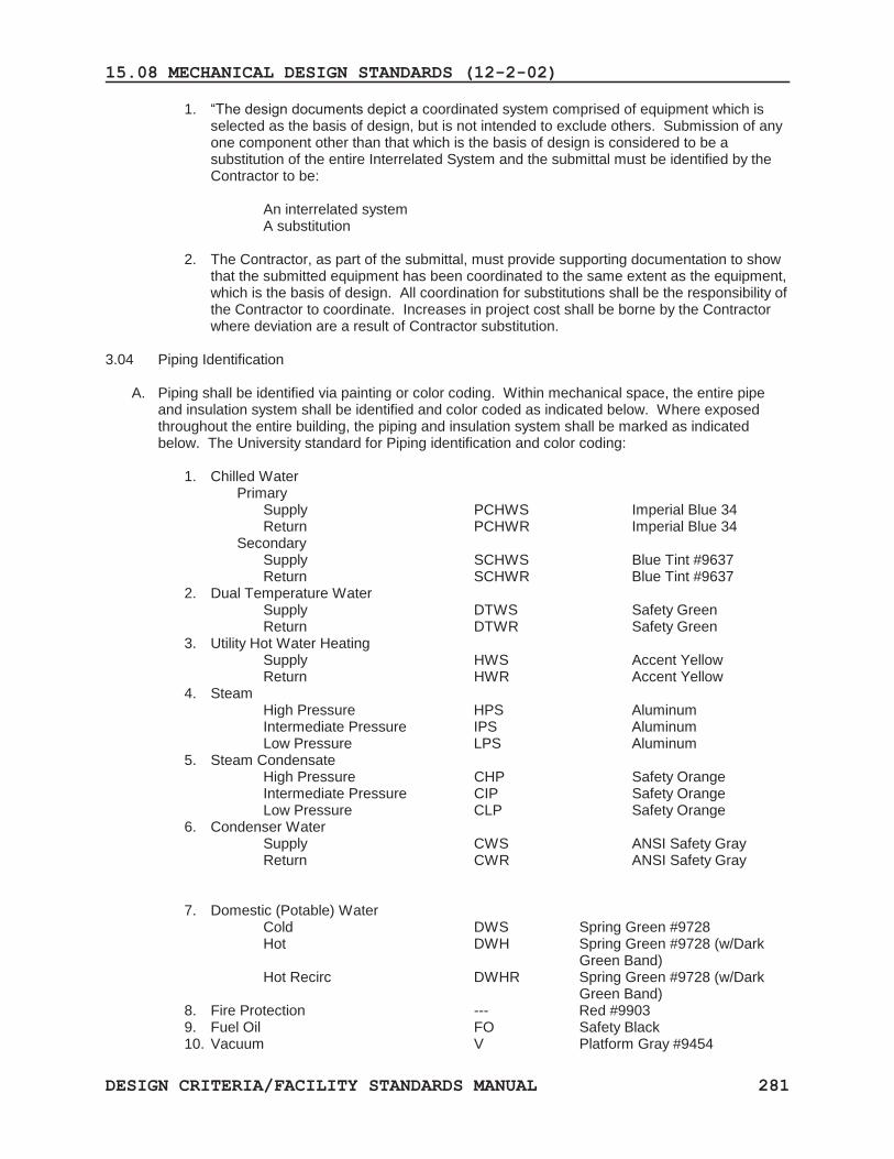
3.04 Piping Identification
A. Piping shall be identified via painting or color coding. Within mechanical space, the entire pipe and insulation system shall be identified and color coded as indicated below. Where exposed throughout the entire building, the piping and insulation system shall be marked as indicated below. The University standard for Piping identification and color coding:
1. Chilled Water
Primary Supply PCHWS Imperial Blue 34 Return PCHWR Imperial Blue 34 Secondary Supply SCHWS Blue Tint #9637 Return SCHWR Blue Tint #9637
2. Dual Temperature Water Supply DTWS Safety Green Return DTWR Safety Green
3. Utility Hot Water Heating Supply HWS Accent Yellow Return HWR Accent Yellow
4. Steam High Pressure HPS Aluminum Intermediate Pressure IPS Aluminum Low Pressure LPS Aluminum
5. Steam Condensate High Pressure CHP Safety Orange Intermediate Pressure CIP Safety Orange Low Pressure CLP Safety Orange
6. Condenser Water Supply CWS ANSI Safety Gray Return CWR ANSI Safety Gray
7. Domestic (Potable) Water Cold DWS Spring Green #9728 Hot DWH Spring Green #9728 (w/Dark Green Band) Hot Recirc DWHR Spring Green #9728 (w/Dark Green Band)
8. Fire Protection --- Red #9903 9. Fuel Oil FO Safety Black 10. Vacuum V Platform Gray #9454
15.08 MECHANICAL DESIGN STANDARDS (12-2-02)
DESIGN CRITERIA/FACILITY STANDARDS MANUAL 282
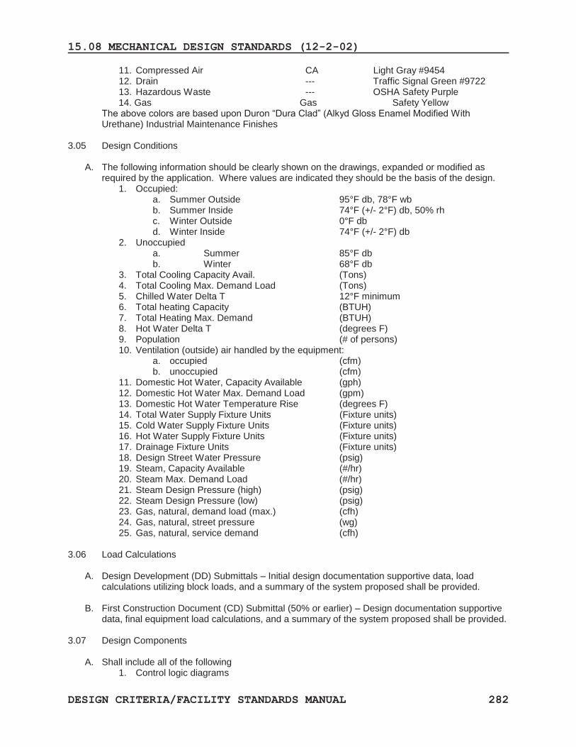
11. Compressed Air CA Light Gray #9454 12. Drain --- Traffic Signal Green #9722 13. Hazardous Waste --- OSHA Safety Purple
14. Gas Gas Safety Yellow The above colors are based upon Duron “Dura Clad” (Alkyd Gloss Enamel Modified With Urethane) Industrial Maintenance Finishes
3.05 Design Conditions
A. The following information should be clearly shown on the drawings, expanded or modified as required by the application. Where values are indicated they should be the basis of the design.
1. Occupied: a. Summer Outside 95°F db, 78°F wb b. Summer Inside 74°F (+/- 2°F) db, 50% rh c. Winter Outside 0°F db d. Winter Inside 74°F (+/- 2°F) db
2. Unoccupied a. Summer 85°F db b. Winter 68°F db
3. Total Cooling Capacity Avail. (Tons) 4. Total Cooling Max. Demand Load (Tons) 5. Chilled Water Delta T 12°F minimum 6. Total heating Capacity (BTUH) 7. Total Heating Max. Demand (BTUH) 8. Hot Water Delta T (degrees F) 9. Population (# of persons) 10. Ventilation (outside) air handled by the equipment:
a. occupied (cfm) b. unoccupied (cfm)
11. Domestic Hot Water, Capacity Available (gph) 12. Domestic Hot Water Max. Demand Load (gpm) 13. Domestic Hot Water Temperature Rise (degrees F) 14. Total Water Supply Fixture Units (Fixture units) 15. Cold Water Supply Fixture Units (Fixture units) 16. Hot Water Supply Fixture Units (Fixture units) 17. Drainage Fixture Units (Fixture units) 18. Design Street Water Pressure (psig) 19. Steam, Capacity Available (#/hr) 20. Steam Max. Demand Load (#/hr) 21. Steam Design Pressure (high) (psig) 22. Steam Design Pressure (low) (psig) 23. Gas, natural, demand load (max.) (cfh) 24. Gas, natural, street pressure (wg) 25. Gas, natural, service demand (cfh)
3.06 Load Calculations
A. Design Development (DD) Submittals – Initial design documentation supportive data, load calculations utilizing block loads, and a summary of the system proposed shall be provided.
B. First Construction Document (CD) Submittal (50% or earlier) – Design documentation supportive
data, final equipment load calculations, and a summary of the system proposed shall be provided.
3.07 Design Components
A. Shall include all of the following 1. Control logic diagrams
15.08 MECHANICAL DESIGN STANDARDS (12-2-02)
DESIGN CRITERIA/FACILITY STANDARDS MANUAL 283
2. System schematics 3. Points lists 4. Component descriptions 5. Sequence of operation 6. Flow diagrams 7. Building Riser diagrams for supply, return, and exhaust systems
3.08 Drawings
A. The A/E shall prepare and submit for review and approval, drawings at schematic, Design Development, 50%, 95%, and 100% completion.
B. All elements of the Work shall be properly coordinated to insure that there are no conflicts between disciplines or between the drawings and the specifications.
C. In general, abbreviations should be avoided except those which are generally understood and accepted and listed in the legend and symbols list.
D. Drawings shall be drawn using AutoCAD 2000 or a later version and provided in electronic format with the 100% submittal.
E. Mechanical drawings shall indicate university assigned room numbers, and have column line designations.
F. Mechanical areas – The designer shall provide a layout (¼” = 1 foot scale or larger) of all of the following rooms, to ensure that the equipment will fit in the allotted space.
1. Mechanical rooms 2. Electrical rooms 3. Restrooms 4. Kitchens 5. Labs 6. Clean rooms 7. Areas with a large quantity of mechanical piping or equipment
G. Congested areas – The designer shall identify potential congested areas where mechanical, electrical, plumbing, and fire protection piping and/or equipment are to be installed, and shall provide appropriate cross sections (at a minimum of ¼” scale).
H. Service clearances – The drawings shall indicate the manufacturers recommended service clearance requirements around all mechanical equipment.
I. Plumbing Drawings – the designer shall provide plans (1/8” = 1 foot scale or larger) that provide: 1. Indicate all piping on the floor-level in which it will be installed. 2. Indicate the locations of main waste lines, stacks, and vents as well as all service mains,
including those for water, air, gas, and vacuum. 3. Indicate all pieces of equipment – including but not limited to, pumps, tanks, generators,
pressure reducing valves, and other appurtenances—showing their location and required piping connections.
J. Site utility Plans – The designer shall provide a site plan (1” = 40 foot scale or larger) that shows the following; 1. The routing of proposed new external utilities from each new building to each
point of connection to the facilities utility systems. Indicate all utility lines that are to be abandoned, removed, or rerouted. 2. All existing utilities within the project site based on both the information provided by the university and the designer’s field investigation. 3. Pipe runs shall indicate pipe type and size, and shall show all valves, fixtures, etc.
K. Mechanical Drawings – The designer shall provide plans (1/8” = 1 foot scale or larger) that provide:
1. The location of each piece of equipment including, but not limited to; air handling units, chillers, cooling towers, pumps, converters, expansions tanks, boilers, fans, fan coil units, and other equipment. 2. All ductwork.
3. Indicate all piping runs (including type and sizes). Show all valves, fixtures, etc. 4. Show all areas served for each air handler on small scale drawings, with cross- hatched areas to differentiate between air handling units.
15.08 MECHANICAL DESIGN STANDARDS (12-2-02)
DESIGN CRITERIA/FACILITY STANDARDS MANUAL 284
L. Plumbing, HVAC, and sprinkler drawings shall be presented as three separate drawing sets.
3.09 Specifications A. Specifications shall include the requirement for the contractor to provide Operation and
Maintenance manuals. Manuals shall be supplied with each major piece of equipment. O&M manuals shall include all applicable design calculations used in sizing components. Wiring diagrams, spare parts lists, vendor contact numbers, warranty information, and certificates shall be included.
DESIGN CRITERIA/FACILITY STANDARDS MANUAL 285
15.09 SCUB CONCEPT (6-01)
The University, with a central steam distribution system and an electric distribution system, has standardized on a concept called the Satellite Central Utilities Building (SCUB).
At strategic locations around campus, steam and electricity is used to produce chilled water, hot water and sometimes, domestic hot water. From the SCUB, these services are delivered to the surrounding buildings. SCUBs are either stand alone buildings, or integrated into new campus buildings.
The program document will make it clear whether a SCUB is to be part of the design. In the event that it is, standards and guidelines for SCUB design will be given to the designer.
Variable flow, new construction Decoupling via Plate & Frame heat exchangers Selections shall be made by: 1. Alpha-Laval 2. Tranter 3. Bell & Gosset 4. Mueller 5. No substitutions allowed.
15.10 APPENDIX
DESIGN CRITERIA/FACILITY STANDARDS MANUAL 286
Discussion of what could be alleged to be cost premiums resulting from these standards.
Generally, the baseline standard is that of Institutional design, not commercial design.
Part One HVAC I. General A. HVAC Design Conditions
The prohibition of control schemes which vary the cooling coil temperature rules out using the more common, low cost control schemes; but these have generally been discredited as institutions seek to avoid litigation related to Indoor Air Quality (IAQ).
Related is:
B. Ventilation - Granted, the University’s adherence to ASHRAE
Standard 62 is beyond the requirements of typical local codes. For example, the ASHRAE standard rules out using windows for ventilation of remodeled campus buildings unless the ventilation can be demonstrated (a defacto prohibition of this typical low-cost approach). Local codes atypically do not incorporate this demonstration provision. However, in litigating IAQ issues, liability has been assessed in cases where local codes allowed less stringent ventilation practices, but the professional HVAC designers were aware of the more stringent provisions of the ASHRAE standard.
(Note that “decoupled ventilation” is promulgated as the University’s preferred method. The first cost implications of this are worth noting:
a. If designed simply, i.e. not incorporating heat-
reclaim and other costly enhancements, the decoupled (stand-alone) ventilation unit is typically a small portion of the total HVAC system first cost. Most of the total HVAC system first cost relates to the other, heating/cooling functions.
15.10 APPENDIX
DESIGN CRITERIA/FACILITY STANDARDS MANUAL 287
To quantify: If the sheet metal ventilation duct system is taken to be the element which would not otherwise have been installed, the first cost premium is around $0.60/ s.f. (1999 dollars); less than 2 of 1% of the total cost to construct a typical campus building.
And there are compensating savings which approach, and may exceed, the premium cost. Using this (relatively high cost) approach to ventilation allows the use of simple, low cost, easy to maintain heating/cooling components elsewhere throughout the HVAC system ( including fan-coil units).
To illustrate, in the case of a fan-coil unit system, the avoided costs include :
- The cost to create openings in the outside
wall for ventilation air. - The cost of the associated louvers - The cost to upsize all the air side terminals
to handle the ventilation cooling, dehumidification and heating load
- The cost of more sophisticated fan-coil unit controls ( decoupling the ventilation allows fan cycling (no automatic control valve) for space temperature control.
b. Further, the University, at a later date, can solicit
proposals from performance contractors to replace / augment the decoupled ventilation units in order to reduce the operating energy cost. Typically, performance contractors receive their payment from the savings, which can be demonstrated by measurements before and after.
The first cost premium situation and the offsetting savings - varies with each application. Generally, our position is that no first cost premium is involved. In addition, the litigation cost avoidance is a benefit.
15.10 APPENDIX
DESIGN CRITERIA/FACILITY STANDARDS MANUAL 288
Part One - Duct liner Control of sound in HVAC systems is necessary. It is accomplished by one of the following methods: a. Mechanical means such as oversized, more costly ducts ( for
low air velocity), sound traps inserted into ducts custom fabricated sound attenuators. The premium cost implications are obvious.
b. “Noise cancellation” electronically generated sound, the
Amirror image of the offensive noise - propagated such that it cancels the offensive noise. Again, the premium cost implications are obvious
c. Acoustical (fiberglass) duct liner.
Note - Fiberglass liners which erode and discharge particles into the HVAC supply air stream, have been implicated in IAQ problems. Also, fiberglass duct liner which becomes wett can harbor colonies of microbial growth, with IAQ liability implications.
Fiberglass, including fiberglass duct liners, has not been declared an IAQ issue, so the University chooses to not impose an outright ban on the use of the material. The University reserves the right to ban the product in special cases, and the program will state this.
Instead, the University requires that all duct liner, where used, be polymer coated.
The University’s requirement for coated fiberglass liners parallels the industry trend toward standardizing on this variation on the formerly common (uncoated) duct liner material.
Uncoated fiberglass duct liner will shortly become unavailable, so the cost premium for the coated variety is, we suggest, a moot point.
The limitation on the application of even coated fiberglass duct liner (where the application is subject to wetting) mandates alternative (closed cell foam)
15.10 APPENDIX
DESIGN CRITERIA/FACILITY STANDARDS MANUAL 289
materials, at a premium of around $2.50 per s.f. of liner, but the premium applies only to a very limited area of the entire duct system.
To quantify: In a 100,000 s.f building renovation project, with a $15, 000,000 budget (1999 dollars), 300,000 s.f. of duct surface area would be typical. Of that, 10% of the liner area is likely to be subject to wetting, thus prescribed to be a more expensive, closed cell product.
30,000 s.f. at $2.50 / s.f. = $75,000; less than one half of one percent first cost premium to the project. $75,000 is also less than the cost of the typical mechanical means of HVAC noise control such as low speed fans, large ducts, insertion sound traps (attenuators) etc.
The avoidance of IAQ liability, we submit, compensates for the slight cost premiumPart One HVAC systems
General Prohibition on ceiling plenums and mechanical rooms used as return air plenums. Installing a system of return air sheet metal ductwork throughout the building is the alternative. Such a system adds around $2.50/s.f. to construction cost, approximately 1.6% of the total construction cost. However, it is difficult to consider this a premium: a. Ceiling plenums are common in commercial applications, where
flexibility in office layouts is a paramount concern. Space layouts in institutions are more permanent and institutions generally rely on return air ducts, and use HVAC concepts that support them.
b. Absent a return air duct system, speech privacy between
adjacent spaces must be developed, and the cost of accomplishing this can exceed $2.50 / s.f.
15.10 APPENDIX
DESIGN CRITERIA/FACILITY STANDARDS MANUAL 290
Part Three Sprinkler systems In cases of new construction, the life safety code mandates sprinklers, so there is no cost premium. The “premium cost” issue arises in the case of considering sprinkler systems in the smaller renovation projects - where the renovation cost is less than the cost of a new building - i.e. the codes do not mandate sprinklers and the University is free to use a minimal compliance to codes strategy in the (understandable) pursuit of lowest cost construction. The point is that sprinkler systems, even where not specifically required by code, can sometime avoid the cost of other, often costly, architectural modifications to meet code in renovation projects. By way of illustration, it is not unusual for a renovation project to pose the following design (and cost) dilemma: - Double loaded corridors requiring a fire rating of the
corridor walls - Non rated doors opening to the corridor - A required retrofit to rated corridor doors, with door closers
to establish and maintain the fire rating. Open fire rated doors are not fire rated
- A programmatic requirement to keep the fire rated corridor
doors open, begetting: - A need for electric door hold-open devices, tied into the fire
detection/alarm system is expensive and a tripping hazard
In similar cases on campus, installing a sprinkler system has been shown to cost the same, or less, than making all the required architectural modifications for code and program compliance.
Furthermore, in the stairwells of many older campus buildings, there will already exist a (University-installed) fire standpipe. This amounts to a head start on the cost of a sprinkler system installation.
15.10 APPENDIX
DESIGN CRITERIA/FACILITY STANDARDS MANUAL 291
Thus - Before opting for no sprinklers to control cost, the University will exercise and require the A/E to exercise - due diligence to examine the total cost of code compliance.
The adjusted differential cost even if a premium - may be tolerable in light of the other life safety advantages afforded by sprinklers.
15.11 METERS, WATER FLOW AND ENERGY (BTU) (12-2-02)
DESIGN CRITERIA/FACILITY STANDARDS MANUAL 292
PART 1 – GENERAL 1.01 SUMMARY
A. This section outlines the requirements for the furnishing of equipment and installation of water flow and energy (BTU) meters.
1.02 SUBMITTALS A. Product Data: Include detailed manufacturer’s specifications for each component specified.
Include data sheets reflecting the model numbers, features, ratings, performance, power requirements, and dimensions. The information provided shall be in sufficient detail to confirm compliance with the requirements outlined in this specification.
PART 2 – PRODUCTS 2.01 METER
A. Furnish and install a Thermal Energy Metering System or flow meter for each of the locations specified.
B. The meter shall be a clamp-on design employing non-intrusive ultrasonic flow metering. C. The meter shall be digital microprocessor based utilizing both “Transit-Time” flow measuring
technique and “Doppler Fourier”. D. The meter shall have an accuracy of 0.02 degrees F. E. The flow meter shall have the ability to calculate and display the following values
1. volumetric flowrate 2. flow velocity 3. total flow 4. liquid sonic velocity 5. liquid aeration/cavitation 6. Reynolds Number
F. The energy (BTU) meter shall have the ability to calculate and display the following values 1. volumetric flowrate 2. flow velocity 3. total flow 4. liquid sonic velocity 5. liquid aeration/cavitation 6. Reynolds Number 7. energy/BTU rate 8. total energy 9. supply temperature 10. return temperature 11. differential temperature
G. The flow and energy (BTU) meter shall have internal memory of at least 1 megabyte for storage of data on a continuous basis and the ability to store application data for a minimum of 1000 points as a “datalogger”.
H. Downloading of the “datalogger” information to personal computers (PCs) shall not require proprietary software to be installed on the PC, but will utilize standard “off-the-shelf” “windows” software.
I. The energy (BTU) meter shall provide self and application diagnostics to isolate any fault conditions due to either equipment failure of abnormal process conditions.
J. The flow and energy (BTU) meter electronics shall be powered by 110/120 VAC 60Hz. K. The flow and energy (BTU) meter shall have an accuracy of ± 1% of flow over a ± 40 fps flow
range. L. Repeatability shall be 0.1% of flow with a flow sensitivity of .01 fps (minimum) at any flowrate,
including no flow conditions.
15.11 METERS, WATER FLOW AND ENERGY (BTU) (12-2-02)
DESIGN CRITERIA/FACILITY STANDARDS MANUAL 293
M. The flow and energy meter shall also possess the following capabilities: 1. Cavitation and Aeration Detection1 2. Internal Pipe wall Build-up Detection 3. Security password protection for individual sites. 4. Reverse Flow and Empty Pipe Detection 5. Direct Digital Temperature measurement via precision matched 1000ohm
Platinum RTD pair and four-wire cable connection 6. Certified for CE Mark (EMI immunity and compatibility standards).
N. Flow meter shall be a Controlotron Model 1010N (or latest model) or approved equal. O. Energy (BTU) meter shall be a Controlotron Model 1010EDN (or latest model) or approved
equal.
2.02 COMMUNICATIONS A. The meter system shall communicate with and be compatible with the University’s Central
Control and Monitoring System (CCMS) using Lonworks LAN (FTT10ALAN) as well as 4-20 MADCV (isolated) output.
PART 3 – EXECUTION Not used
15.12 MECHANICAL EQUIPMENT ROOM REQUIREMENTS (09-30-04)
DESIGN CRITERIA/FACILITY STANDARDS MANUAL 294
PART 1 – GENERAL 1.01 SUMMARY
A. Mechanical rooms shall be designed with maintenance requirements and adequate safety
provisions in mind. Equipment must be fully accessible to allow for proper servicing, including adequate space to disassemble all pumps, motors and chillers. Provide access for all required trap primers. This section addresses minimum requirements for the design of mechanical and electrical rooms. It shall be noted, specific code requirements more stringent shall apply. This section is intended to supplement and clarify the University’s requirements, not supersede code requirements.
PART 2 – PRODUCTS
Not used PART 3 – EXECUTION 3.01 DRAWINGS
Access requirements required for below grade ME
A. Main mechanical rooms which house chillers, pumps, steam to water converters, plate and frame chilled water heat exchangers and associated appurtenances should be located at grade level. Should a main mechanical room be located below grade, a vehicular ramp with an appropriately sized door should be provided to facilitate equipment replacement. Where the installation of an exterior mechanical room drive way and loading dock is not possible, a service well including permanent rigging beam with electric hoist shall be provided. Exterior roof top air handlers are to be avoided. For other roof mounted equipment, provide exterior roof walkways to allow servicing of equipment accessible through standard door ways with permanent stairs or built-in ladders. For large equipment, removable louvers or wall panels shall be provided.
B. Air conditioning condensate lines shall drain to storm drains. Dumping of air conditioning
condensate on roofs shall be avoided. Refer to the WSSC Plumbing Code for the proper drainage requirements.
C. Provide at least one (1) sanitary floor drain for every 144 square foot in each equipment room.
Locate drains away from walking areas and not beneath equipment. Slope floor to drain. Air conditioning condensate lines within mechanical rooms shall be collected and piped to the storm drains systems via open site funnel drains.
D. Provide thermostatically controlled mechanical ventilation in all mechanical and electrical
equipment rooms.
i. Ventilation shall be provided to insure air exchange, including fresh supply air and exhaust, to atmosphere.
ii. Exhaust shall not be re-circulated to building ventilation systems. iii. Mechanical/Electrical equipment rooms (MER) shall be permitted to utilize outside
louvered dampers, adequately sized to provide fresh air supply where MER exhaust fan(s) are used.
15.12 MECHANICAL EQUIPMENT ROOM REQUIREMENTS (09-30-04)
DESIGN CRITERIA/FACILITY STANDARDS MANUAL 295
iv. Ventilation quantities shall be, at minimum, equal to 0.5 cfm per square foot of machinery room area. Specific code requirements more stringent shall apply. This section is intended to supplement and clarify the University’s requirements, not supersede code requirements.
v. Air quantities shall insure a maximum temperature rise of 18ºF above inlet air temperature or a maximum MER temperature of 104ºF. Where required, MER cooling shall be required to adhere to identified temperature requirement.
vi. MER equipment rooms shall be provided, when required, to provide minimum heating of MER to meet a winter heating set point of 65ºF adjustable.
E. Where refrigeration equipment is installed, adherence to all requirements identified in ASHRAE
Standard 15 shall be adhered to.
i. The University, Facilities Management, HVAC Systems (authority of jurisdiction) identifies a requirement to provide refrigerant specific alarms.
ii. In lieu of SCUBA provision, remote visual/audible alarming at all MER entrances shall be installed. Individual alarms shall be provided with a reset and clear signage identifying to campus community to contact: HVAC Systems, ext. 57052, Work Control, ext. 52222. Signage shall be located outside MER entrance. Reset shall be installed within MER directly behind signage.
iii. Refrigerant alarms shall only reset (automatically) when refrigerant concentrations fall below levels identified for each refrigerant as referenced by ASHRAE Standards 34 and Standard 15.
F. Equipment rooms shall not be used for outside or return air plenums.
G. Each component of an air handling system shall be spaced so there is ample room on all sides for
inspection and maintenance (filter removal, bearing replacement, coil replacement, cleaning, etc.) as defined in the equipment manufacturer’s information. At minimum, service clearance around equipment shall be maintained at 42”. All air handlers shall provide for clear “coil pull clearance dimensions as required.
H. Each piece of mechanical equipment shall be provided with equipment service clearance around
the equipment as identified by the manufacturer’s literature. When service clearances are not available, service clearance around mechanical equipment shall be at minimum 42" (e.g., pumps, strainers, water heaters, heat exchangers). Chillers shall be provided at minimum 6 foot service clearance on all sides for access. Tube pull space shall additionally be provided on at least one side of the evaporator and condenser. Chiller manufacturer clearance data shall be reviewed for maximum service clearance dimensions on all sides and on top of chiller. Mechanical HVAC engineer shall identify on the drawings, with dotted lines or other clearly identifiable method, all service clearance dimensions (e.g., chiller tube pull clear area shown on mechanical plan as an area to be avoided for installation of mechanical equipment).
I. There shall be a minimum of 42" clearance around electrical equipment control points (e.g.,
breaker panels) and heat-producing equipment (e.g., water heater). Specific code requirements more stringent shall apply. This section is intended to supplement and clarify the University’s requirements, not supersede code requirements.
J. Suspended equipment shall be provided with permanent platforms for maintenance including
appropriate access to platforms.
15.12 MECHANICAL EQUIPMENT ROOM REQUIREMENTS (09-30-04)
DESIGN CRITERIA/FACILITY STANDARDS MANUAL 296
K. M/E room shall have fire suppression systems unless specifically exempted by the code authority having jurisdiction.
L. Walls of equipment rooms, when located on occupied floors, shall be sound attenuated
(application specific).
M. Equipment and piping shall be laid out in a manner that will not require equipment to be removed to get to another piece of failed equipment.
N. For below grade mechanical rooms, provide a dual sump pump, set as required. Connect to
emergency power system.
O. Provide convenience outlet within twenty-five feet of each piece of equipment.
P. Provide 40 fc (minimum) of uniform lighting, when measured at a height 5’ off the finished floor, throughout room. Provide task lighting at control panels. Specific code requirements more stringent shall apply. This section is intended to supplement and clarify the University’s requirements, not supersede code requirements.
Q. Main MER entrance shall be provided with a card reader access system to be installed, modified,
or upgraded in the project, then all mechanical rooms in the project shall have card readers installed at all entrance doors.
R. All electrical control systems (breaker panels, switchgear, transformers, etc.) must be labeled with
the arc flash analysis rating.
S. Emergency egress requirements.
i. Shall comply with the State Fire Prevention Code, the current National Electrical Code and the current edition of the National Electrical Safety Code.
ii. Any door in a M/E room that is not a direct pathway from the building must be prominently labeled “NO EXIT”.
iii. Electrical rooms shall have not less than two (2) doors for egress.
T. Emergency lighting will be present in all M/E rooms in compliance with the State Fire Prevention Code, the current National Electrical Code, and the current edition of the National Electrical Safety Code.
U. M/E rooms with electrical equipment operating at or over 600 volts (OSHA High Voltage definition)
will incorporate the following additional design specifications.
i. High voltage equipment will be isolated from other areas of the building in separate and secured room(s). No mechanical or electrical control systems, except those directly servicing or serviced by the high voltage equipment, shall be installed in these rooms.
ii. Access to and egress from these rooms must be directly to the outdoors or building corridors. Any exception to this must be specifically reviewed and approved by the University, Facilities Management Operations Department and Environmental Safety Code Services.
iii. Doors to rooms containing high voltage equipment will be signed per OSHA and National Electrical Code requirements.
15.12 MECHANICAL EQUIPMENT ROOM REQUIREMENTS (09-30-04)
DESIGN CRITERIA/FACILITY STANDARDS MANUAL 297
iv. Rooms will incorporate a sufficient number and type of access/egress means to comply with the current editions of the National Electrical Code and the National Electrical Safety Code.
v. Access/egress means must be constructed per the requirements of the current editions of the National Electrical Code and the National Electrical Safety Code for high voltage rooms.
vi. No material or storage structures shall be installed in high voltage rooms. vii. Electrical systems shall be designed with appropriate isolation devices to permit
maintenance in a de-energized state. viii. Any equipment additions/modifications or structural alterations in high voltage
rooms must be reviewed and approved by the University Engineer and Environmental Safety Code Services.
V. M/E rooms with electrical switch gear at least six feet in width and with current capacity of at least
1200 amperes will incorporate the following additional design specifications. i. Rooms will incorporate a sufficient number and type of access/egress means to
comply with the current editions of the National Electrical Code and the National Electrical Safety Code and NFPA 70E-2004.
ii. Any equipment additions/modifications or structural alterations in these rooms must be reviewed and approved by the University, Facilities Management Operations Department and Environmental Safety Code Services.


![[O] cOmpaniessavarinocompanies.com/content/documents/bids... · hvac general notes hvac abbreviations hvac ductwork symbols hvac control symbols chaintreuil jensen stark architectural](https://img.pdfslide.us/doc/110x75/5ae5a13f7f8b9a29048c7dfa/o-compan-general-notes-hvac-abbreviations-hvac-ductwork-symbols-hvac-control-symbols.jpg)