Embed Size (px)
Citation preview

KALLPA INDEPENDENT POWER - COMBUSTION TURBINE FAMILIARIZATION
SPPA-T3000 Control System1 Control System Layout...........................................................................................2
1.1 IO Modules:................................................................................................3
1.2 Technical System Data..............................................................................4
2 Operations Mode:...................................................................................................8
2.1 Plant Displays and Faceplates...................................................................8
2.1.1 How to Login.................................................................................10
2.1.2 Workbench...................................................................................11
2.1.3 Controller Faceplates...................................................................18
2.1.4 SGC Description of Indicators and Command Buttons................24
2.1.5 ASO Description of Indicators and Command Buttons................30
2.2 The Alarm Sequence Display, ASD.........................................................32
2.2.1 Opening the Alarm Sequence Display.........................................32
2.2.2 Acknowledging of Alarms.............................................................34
2.2.3 Analyze Display............................................................................37
2.2.4 Filtering of Alarms........................................................................38
2.2.5 Automatic Acknowledging of Alarms............................................43
2.3 Working With Trend Displays...................................................................44
2.3.1 Opening Trend Displays...............................................................45
2.3.2 Adjusting the Displayed Time Duration........................................46
2.3.3 Dynamic and Static Mode of the Trend Displays.........................46
2.3.4 Reading the Values in the Trend Display.....................................47
2.3.5 Displaying Trends from the Archive.............................................49
2.3.6 Activation of the Optional Scales..................................................51
2.3.7 Add and Remove Signals from a Trend Display..........................52
2.4 Configuring and Viewing Reports.............................................................54
2.4.1 Report Types................................................................................55
2.4.2 Adjusting Date and Time Range (From/To).................................56
2.4.3 Specify a selection of signals:......................................................57
2.4.4 Other settings:..............................................................................58
FOR TRAINING PURPOSES ONLY SPPA T-3000 DOC
SIEMENS CONFIDENTIAL INFORMATION
Page 1 of 58

KALLPA INDEPENDENT POWER - COMBUSTION TURBINE FAMILIARIZATION
SPPA-T3000 Control System
1 CONTROL SYSTEM LAYOUT
Thin Client: enables any computer to access Web applications from any Web Browser over the Internet or a Corporate Intranet without having to install the application on every desktop system.
Network: The Network is an Industrial Ethernet with 100 Mbit/sec, standard protocol TCP/IP. The Network connection points are Optical Switch Modules (OSM) interconnected with redundant Fiber-optic connections between them.
Application Server: The Application Server runs all the Operations, Monitoring, Engineering, and Archiving applications for the system. It is a Microsoft Windows Server operating system, high performance dual processor with built-in redundancy.
Automation Server: The Automation Server is a SIMATIC S7 rack mounted FM417 processor that runs the plant operations for all Input and output devices. The processors are redundant and the Rack can contain an add-on processor (FM 458) to provide high speed data processing down to 2 ms cycle times for special turbine control tasks.
FOR TRAINING PURPOSES ONLY SPPA T-3000 DOC
SIEMENS CONFIDENTIAL INFORMATION
Page 2 of 58

KALLPA INDEPENDENT POWER - COMBUSTION TURBINE FAMILIARIZATION
Field Bus: The field bus connections carry digital Profibus DP input and output signals to and from the Automation Server rack and the Input Modules.
1.1 IO MODULES:
Standard Input Output modules are distributed ET200M racks with a maximum of 8-IO module cards mounted on each. Types and channels per card are listed below.
Standard I/Os Signal Type ChannelsSM 321 DI 24V DC 16SM 321 DI 24V DC x diag 16SM 321 DI 48-125V DC, exp. Temp. 16SM 321 DI 230V AC 16SM 321 DI 24V DC 32SM 322 DO 24V DC / 230V AC 8SM 322 DO 24V DC / 230V AC 8SM 322 DO 24V DC 16SM 322 DO 24V DC 32SM 323 DI 24V DC 16
DO 24V DC 16SM 323 DI 24V DC 8
DO 24V DC 8SM 323 DI 24V DC, exp. Temp. 8
DO 24V DC, exp. Temp. 8SM 331 AI 8SM 331 AI, safe signal 8SM 331 AI 16 Bit 8SM 331 AI 2SM 33 AI Resistance 8SM 331 AI Thermocoupler 8SM 332 AO 4SM 332 AO 8
FOR TRAINING PURPOSES ONLY SPPA T-3000 DOC
SIEMENS CONFIDENTIAL INFORMATION
Page 3 of 58

KALLPA INDEPENDENT POWER - COMBUSTION TURBINE FAMILIARIZATION
Fast IO Modules: AddFEM IO is used to process the high speed IO from and to the Turbine controller. These are capable of 1ms signal time stamping.
Standard I/Os Signal Type Channels
AddFEM SOE 1 ms DI 32
AddFEM AI, 0/4 – 20 mA / + 20 mA /+ 30 mA / 0 – 10 V / + 10 V 12
AO, 0/4 – 20 mA / + 20 mA /+ 30 mA / + 50 mA 8
Counter / Timer + 28 V 3
DO 24 V DC 16
1.2 TECHNICAL SYSTEM DATA
System wide IO capacity The number of IO is not a limiting factor of the system
System wide time accuracy Depending on configured Runtime Container, typically 100ms
SOE accuracy 1ms
Max. amount of User Interfaces / Thin Clients
10
Recommended Internet Browser Microsoft Explorer >= 5.5
Monitors per workplace 2
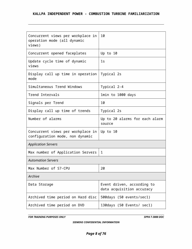
Concurrent views per workplace in operation mode (all dynamic views)
10
Concurrent opened faceplates Up to 10
Update cycle time of dynamic views 1s
Display call up time in operation mode Typical 2s
Simultaneous Trend Windows Typical 2-4
Trend Intervals 1min to 1000 days
FOR TRAINING PURPOSES ONLY SPPA T-3000 DOC
SIEMENS CONFIDENTIAL INFORMATION
Page 4 of 58

KALLPA INDEPENDENT POWER - COMBUSTION TURBINE FAMILIARIZATION
Signals per Trend 10
Display call up time of trends Typical 2s
Number of alarms Up to 20 alarms for each alarm source
Concurrent views per workplace in configuration mode, non dynamic
Up to 10
Application Servers
Max number of Application Servers 1
Automation Servers
Max Number of S7-CPU 20
Archive
Data Storage Event driven, according to data acquisition accuracy
Archived time period on Hard disc 500days (50 events/sec1)
Archived time period on DVD 130days (50 Events/ sec1)
Alarm peak 2000 alarms within 2 sec
Project Container
Number of nodes (technological areas) Not restricted
Dynamic Objects (instances) in a view type Typical 50 to guarantee display call up time, maximum 250. Generally not restricted, but with impact on display call-up time
Colors 84 standard, configurable 16,777,216
Line widths Configurable
Shapes Configurable
3D objects Configurable
Fill patterns 68
Characters Sizes Standard 12, free-scalable
FOR TRAINING PURPOSES ONLY SPPA T-3000 DOC
SIEMENS CONFIDENTIAL INFORMATION
Page 5 of 58

KALLPA INDEPENDENT POWER - COMBUSTION TURBINE FAMILIARIZATION
Function Charts
number of Function Diagram Virtually not restricted, typical <50kb each
Plant Displays
number of Plant Displays Not restricted, typical <50kb each
Plant Display Hierarchy Levels >10, in general not restricted
Trend Displays
number of Trend Displays Not restricted, typically <50kb each
Alarm System
Alarm Types, Priorities, Indicators Standard 8, not restricted, configurable
Blink Rate 1Hz, 2Hz configurable
Runtime Container execution time 10ms to 30s. Generally not restricted, typically 100ms
ETHERNET
Baud rate: 100 mega bits per second
Max. cable length Electrical up to 1.4km / optical up to 150km
Max. number of network participants Not restricted
Runtime Container-Runtime Container communication
<250ms
On board Ethernet ports (physical/redundant) S7-CPU
2/1
Additional Ethernet ports per S7-CPU (physical/redundant)
2/1 (4/2 in total)
FOR TRAINING PURPOSES ONLY SPPA T-3000 DOC
SIEMENS CONFIDENTIAL INFORMATION
Page 6 of 58

KALLPA INDEPENDENT POWER - COMBUSTION TURBINE FAMILIARIZATION
PROFIBUS DP
Baud rate Up to 12 Mbps
Max. cable length Electrical: up to 10 km / optical: up to 100 km
Max. amount of PROFIBUS lines per non-redundant Automation Server
6 (2 integrated on S7-CPU1) and additional 4 CP4343-5 EXT)
Max. amount of redundant PROFIBUS lines per redundant Automation Serve
6 (2 integrated on S7-CPU1) and additional 4 CP4343-5 EXT)
Max amount of PROFIBUS field devices per line1)
125
Max. amount of ET200M stations per line 32
Max. amount of signal modules per ET200M station
8
Max. amount of AddFEM devices per line 50
MODBUS
Modbus Master per Automation Server Generally not restricted, limited by overall system configuration.
Simultaneous slave communication channels per master
Up to 8
FOR TRAINING PURPOSES ONLY SPPA T-3000 DOC
SIEMENS CONFIDENTIAL INFORMATION
Page 7 of 58
KALLPA INDEPENDENT POWER - COMBUSTION TURBINE FAMILIARIZATION
2 OPERATIONS MODE:
The SPPA-T3000 operator interface is a new cutting-edge solution for user-centric process control. With sophisticated alarm features and diagnostic information, it is much more than just a "window on the process". At the first sign of any deviation from normal plant operation, timely user notifications enable you to prevent any negative consequences to the plant operation. This is supported by well-defined and easily recognizable alarm types, which help operators to make the right decisions.
Real-time data displays, high-speed and high-resolution process graphics, alarm screens and other views simplify the review and analysis of live and historical process data. Searching for information is no longer necessary. The active user guidance with direct navigation (live links) and high speed call-up of detailed information allows fast and safe intervention in critical situations while putting all the information you need at your fingertips.
The main elements of Operation with SPPA-T3000 are:
2.1 PLANT DISPLAYS AND FACEPLATES
Plant displays and faceplates allow the operator to monitor and manipulate process control variables, as well as perform tasks such as operating devices, tuning loops, responding to alarms or changing set points. The ability to configure user-specific plant displays without any engineering effort provides customized views of the plant according to specific user needs.
FOR TRAINING PURPOSES ONLY SPPA T-3000 DOC
SIEMENS CONFIDENTIAL INFORMATION
Page 8 of 58

KALLPA INDEPENDENT POWER - COMBUSTION TURBINE FAMILIARIZATION
Alarm System
Alarms are used to inform the operator about deviations from the regular or planned operation in the power plant (process alarms) or about malfunctions in the I&C System (I&C alarms). Alarms can be displayed in the Alarm Sequence Display, in plant displays, or can be reported in logs.
Point View
The point view allows the operator to display and modify the complete data set of a point, including live values and alarm states. The operator is able, through a single mouse click, to call up all information about a point from any station.
Find Tags
Find Tags allows the user to review point-related information. Points with common characteristics, status conditions or qualities can be generated in a list.
Dynamic Function Diagrams
Dynamic Function Diagrams contain live data indicating current signal values, such as equipment or release states. Navigation from a Faceplate to the corresponding Function Diagram is possible with a single mouse click.
Trend Displays
Trend displays are used to display archived or live values of process data in the form of a line chart.
Report System
The report system is used to extract any historical information that a user requires from the system archive. Reports can be triggered either manually or event-driven. Many different reports are available, e.g.:
Status Reports
Sequence Reports
Trip Reports
Archive System
All events and operator actions of the entire plant are efficiently stored in the Archive System. All data is stored in a central real-time database in chronological order, including a timestamp, a value and a quality status.
FOR TRAINING PURPOSES ONLY SPPA T-3000 DOC
SIEMENS CONFIDENTIAL INFORMATION
Page 9 of 58

KALLPA INDEPENDENT POWER - COMBUSTION TURBINE FAMILIARIZATION
Online Help
Context-sensitive online help provides the required information as quickly as possible, thereby eliminating time consuming searching through user manuals.
2.1.1 How to Login
If any problems are encountered during the login process, consult the system specialist for the project.
1. Start the Client Computer.
2. Start the Web Browser on the Client Computer.
The user needs the URL of the SPPA-T3000 Server for the project. This URL is available from the system specialist for the project.
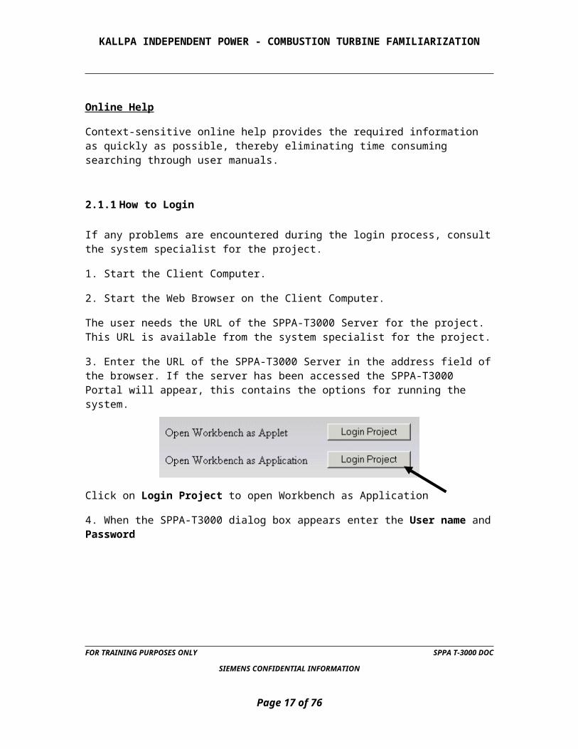
3. Enter the URL of the SPPA-T3000 Server in the address field of the browser. If the server has been accessed the SPPA-T3000 Portal will appear, this contains the options for running the system.
Click on Login Project to open Workbench as Application
4. When the SPPA-T3000 dialog box appears enter the User name and Password
The user must be assigned a User name and a Password by the system specialist.
5. Click on Login.
FOR TRAINING PURPOSES ONLY SPPA T-3000 DOC
SIEMENS CONFIDENTIAL INFORMATION
Page 10 of 58

KALLPA INDEPENDENT POWER - COMBUSTION TURBINE FAMILIARIZATION
6. If the Login was successful the Workbench will open.
Users are assigned user roles in the system. The user role defines the access rights the user has in the system e.g. to modify logic, or to operate the plant. If the user has been assigned different user roles, the Workspace Selection dialog box will appear. Then the user can select which workspace the Workbench will start up in.
2.1.2 Workbench
The user can select which workspace the Workbench will start up in when the Workspace Selection dialog box appears.
Orientation (for text faceplates)
Once the Workbench has opened the user can orientate him or herself to the workbench layout, learn how to open and close views in the Workbench, and how to use the Operation Mode.
What is available from the workbench?
The Workbench is the central or uppermost view in the SPPA-T3000 system; all other views are accessed from the Workbench. The SPPA-T3000 views cater to the different needs of users e.g. engineers, operators, maintenance staff. The views are opened as windows in the Workbench Work Area. The following views can be opened from the Workbench:
FOR TRAINING PURPOSES ONLY SPPA T-3000 DOC
SIEMENS CONFIDENTIAL INFORMATION
Page 11 of 58

KALLPA INDEPENDENT POWER - COMBUSTION TURBINE FAMILIARIZATION
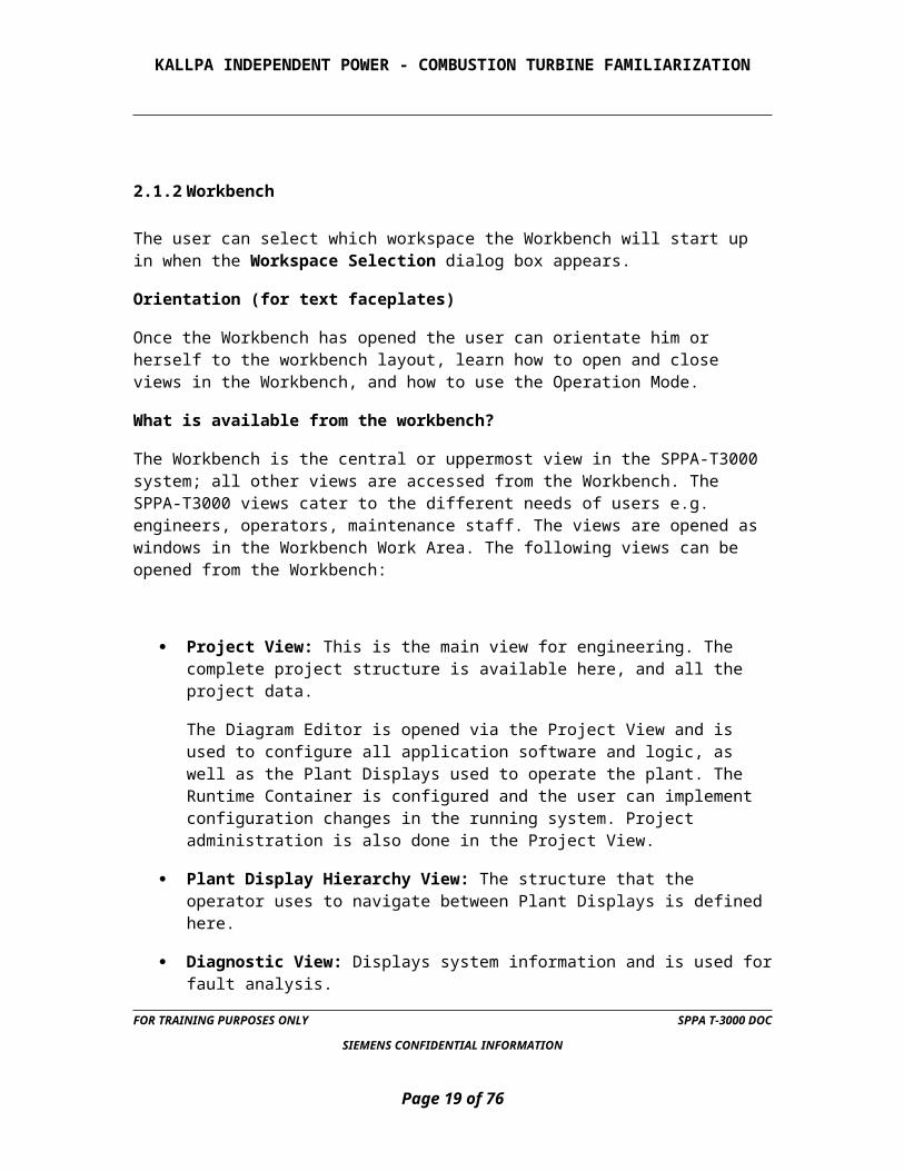
Project View: This is the main view for engineering. The complete project structure is available here, and all the project data.
The Diagram Editor is opened via the Project View and is used to configure all application software and logic, as well as the Plant Displays used to operate the plant. The Runtime Container is configured and the user can implement configuration changes in the running system. Project administration is also done in the Project View.
Plant Display Hierarchy View: The structure that the operator uses to navigate between Plant Displays is defined here.
Diagnostic View: Displays system information and is used for fault analysis.
Alarm Sequence Display: All Alarms are displayed and organized in the ASD.
Prototype Editor: Used to create and edit user defined Pictograms and Faceplates.
Reports: Used to extract and view historical process information from the archive.
Operation Mode is also selected in the Workbench, in this mode the plant is controlled and monitored.
2.1.2.1 How to Open a View in the Workbench?
To open the Project View, Plant Display Hierarchy View, Alarm Sequence Display, Diagnostic View etc. click on Applications on the menu bar, and then click on the view in the drop down menu.
The view will then open in the Work Area.
FOR TRAINING PURPOSES ONLY SPPA T-3000 DOC
SIEMENS CONFIDENTIAL INFORMATION
Page 12 of 58

KALLPA INDEPENDENT POWER - COMBUSTION TURBINE FAMILIARIZATION
As many views as required can be opened simultaneously and arranged in the Workbench (an example of a Workbench with an opened Project View, Diagnostic View, Alarm Sequence Display, Plant Display Hierarchy View and a Plant Display with an opened Faceplate is shown here).
In the windows toolbar of the Workbench, a button can be seen for each open view. If the views are overlapping or overlaying each other, click on the button in the windows toolbar to make the view visible.
FOR TRAINING PURPOSES ONLY SPPA T-3000 DOC
SIEMENS CONFIDENTIAL INFORMATION
Page 13 of 58

KALLPA INDEPENDENT POWER - COMBUSTION TURBINE FAMILIARIZATION
To start (or stop) Operation Mode click on Mode on the menu bar then click on Operation Mode in the dropdown menu.
Operating With Plant Displays (For Text Faceplates)
To supervise any system or to operate any equipment in the plant, the operator has to open the specific Plant Display in the workbench. Plant Displays typically include a schematic representation of the plant layout and processes and include dynamic elements for operation and indicators for supervision.
Any technological system in the plant has a corresponding plant display. All existing Plant Displays are inserted in the Plant Display Hierarchy. The logical organization of the hierarchy makes it easy to navigate to the several technological systems of the plant by selecting the corresponding Plant Display.
The example of a Plant Display configured in the implementation example is created to show how to open Plant Displays and arrange the view, and how to interpret the elements in the diagram. Operation with Faceplates is then explained.
FOR TRAINING PURPOSES ONLY SPPA T-3000 DOC
SIEMENS CONFIDENTIAL INFORMATION
Page 14 of 58

KALLPA INDEPENDENT POWER - COMBUSTION TURBINE FAMILIARIZATION
2.1.2.2 How to Open a Plant Display?
The Workbench must be in Operation Mode and the Plant Display Hierarchy must be open.
1. In the Plant Display Hierarchy double click on the Plant Display.
2. The Plant Display will now open in the Workbench (in Operation Mode).
The status of the technological systems or of equipment is visualized either by analog or digital indicators for continuously changing values or by binary indicators e.g. for motors and switches. These elements are called dynamic elements. Binary indicators visualize a certain state by a color. E.g. the OFF state of a motor or a pump is indicated by a green motor symbol (pictogram). To operate equipment in the plant, the Faceplate has to be opened.
2.1.2.3 How to Open a Faceplate.
Faceplates can be opened for each Pictogram in the Plant Display. The Faceplate makes a number of functions available for the dynamic element. Especially they are used to give a command to a device such as starting or stopping a motor.
To open the Faceplate for a pump in the display, proceed as follows:
1. Select the pump by clicking on it.
FOR TRAINING PURPOSES ONLY SPPA T-3000 DOC
SIEMENS CONFIDENTIAL INFORMATION
Page 15 of 58

KALLPA INDEPENDENT POWER - COMBUSTION TURBINE FAMILIARIZATION
2. Click the right mouse button to open the context menu, select Open Faceplate.
3. The Faceplate for the pump will open.
Pictograms with opened faceplates are displayed with a border. The color of the border can be defined in the user settings (in this example it is green).
The Faceplate consists of a toolbar to access further views (e.g. curves or diagnostics) for the pump, and all functions necessary to control the pump (e.g. starting or stopping). It's also possible to open the faceplate via double click on the correspondent pictogram.
Using the arrow buttons for navigation between plant displays selection of a diagram by the arrow buttons in the footer of the Workbench:
Use the left arrow to move to the upper hierarchy level,
FOR TRAINING PURPOSES ONLY SPPA T-3000 DOC
SIEMENS CONFIDENTIAL INFORMATION
Page 16 of 58
START
STOP
RESET
KALLPA INDEPENDENT POWER - COMBUSTION TURBINE FAMILIARIZATION
Use the right arrow to move to the lower hierarchy level.
Use the up arrow to select the next diagram in the same hierarchy level, displayed above the current diagram in the tree,
Use the down arrow to select the next diagram in the same hierarchy level, displayed below the current diagram in the tree.
The arrow buttons always refer to the currently selected diagram. Therefore one diagram has to be selected and opened. Arrows are only selectable where a diagram exists, e.g. when there is no lower hierarchy level to the selected diagram the right arrow is not selectable.
If the navigation arrows are not visible then the adjustable parameter, Navigation Buttons Visibility, has been switched off in the Style settings.
Using Individual Navigation Buttons in Plant Displays
Individual requirements can be realized by navigation buttons (Jump Buttons) which are placed at appropriate positions in the Plant Displays:
For navigation to existing trend displays double click on this navigation button and the corresponding trend display opens.
For navigation to other Plant Displays double click on this navigation button and the corresponding plant display opens.
This kind of navigation button is often used to switch over between systems which are closely related to each other, e.g. to switch from a main device to the auxiliaries and vice versa.
2.1.3 Controller Faceplates
There are many types of controller faceplates. The most common ones will be discussed here.
FOR TRAINING PURPOSES ONLY SPPA T-3000 DOC
SIEMENS CONFIDENTIAL INFORMATION
Page 17 of 58

KALLPA INDEPENDENT POWER - COMBUSTION TURBINE FAMILIARIZATION
2.1.3.1 Basic layout:
Logic diagram select
Force points
Diagnostic view Trend
Point information Help Open Notice
Logic diagram select: displays the dynamic logic for the controller.
FOR TRAINING PURPOSES ONLY SPPA T-3000 DOC
SIEMENS CONFIDENTIAL INFORMATION
Page 18 of 58
KALLPA INDEPENDENT POWER - COMBUSTION TURBINE FAMILIARIZATION
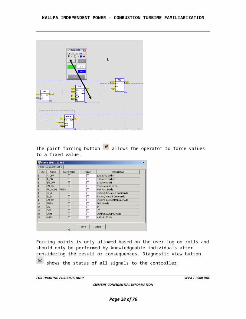
The point forcing button allows the operator to force values to a fixed value.
Forcing points is only allowed based on the user log on rolls and should only be performed by knowledgeable individuals after considering the result or consequences.
Diagnostic view button shows the status of all signals to the controller.
FOR TRAINING PURPOSES ONLY SPPA T-3000 DOC
SIEMENS CONFIDENTIAL INFORMATION
Page 19 of 58

KALLPA INDEPENDENT POWER - COMBUSTION TURBINE FAMILIARIZATION
Trend button displays an instantaneous trend of the controller analog values real time not historical.
Information button gives detailed information about the controller.
FOR TRAINING PURPOSES ONLY SPPA T-3000 DOC
SIEMENS CONFIDENTIAL INFORMATION
Page 20 of 58

KALLPA INDEPENDENT POWER - COMBUSTION TURBINE FAMILIARIZATION
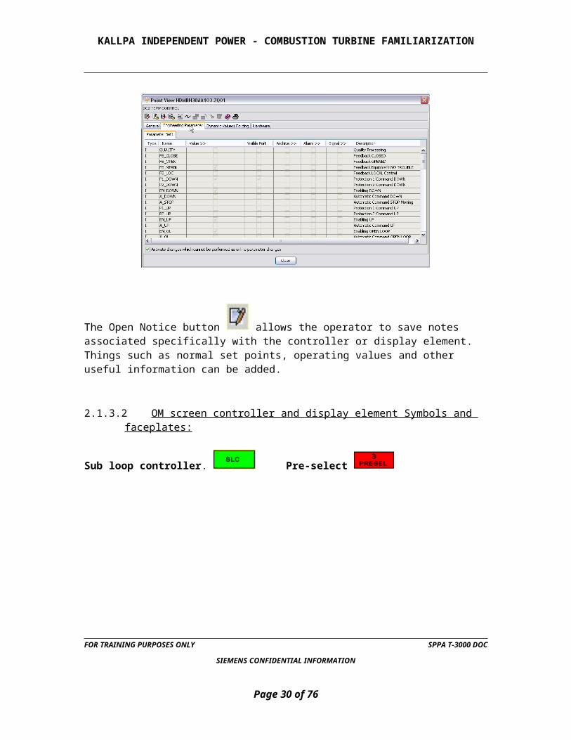
The Open Notice button allows the operator to save notes associated specifically with the controller or display element. Things such as normal set points, operating values and other useful information can be added.
2.1.3.2 OM screen controller and display element Symbols and faceplates:
Sub loop controller. Pre-select
FOR TRAINING PURPOSES ONLY SPPA T-3000 DOC
SIEMENS CONFIDENTIAL INFORMATION
Page 21 of 58

KALLPA INDEPENDENT POWER - COMBUSTION TURBINE FAMILIARIZATION
Set point adjuster
Sub Group controller SGC MODES on pictogram
FOR TRAINING PURPOSES ONLY SPPA T-3000 DOC
SIEMENS CONFIDENTIAL INFORMATION
Page 22 of 58

KALLPA INDEPENDENT POWER - COMBUSTION TURBINE FAMILIARIZATION
2.1.4 SGC Description of Indicators and Command Buttons
Analog value indications:
1. COM (Commissioning): After activation of the commissioning mode automatic signals and protection signals are overridden. The SGC will accept manual commands from the faceplate only. In the commissioning mode no automatic continuation of the step sequence will be preformed by the SGC even if all continuation criteria are available.
To change to the next step when the commissioning mode is active, the Next Step button has to be clicked.
FOR TRAINING PURPOSES ONLY SPPA T-3000 DOC
SIEMENS CONFIDENTIAL INFORMATION
Page 23 of 58
Red/Green
Green
Green/Red
Red
Blue

KALLPA INDEPENDENT POWER - COMBUSTION TURBINE FAMILIARIZATION
2. AUTO / MANUAL: to switch over between automatic and manual mode.
In automatic mode, automatic commands issued at the block inputs are performed. In this mode e.g. a super-ordinate group control function (GC) will affect the SGC operation. By default, in automatic mode the frame of the symbol is light-green.
In manual mode, only those commands are performed which are given from the faceplate. However, protection signals will be processed; protection overrides will be in effect. By default, in manual mode the frame of the symbol is white.
3. ACTIVE STEP: indicates the current active step.
4. NEXT STEP: indicates the next step to be activated. In the case that the current step is a branch, then the target step with the lowest sequence number is indicated.
5. NEXT STEP: forces the subgroup control to change over to the next step even if the requirements are not met. In COMMISSIONING MODE this button must be used to proceed to the next step.
6. ACCEPT STEP: needed in the inching mode (step forcing).If a requirement to continue is missing; the SGC will not switch over to the next step. However, the operator may manually proceed to the next step using the NEXT STEP button. In the case that the activated step is a branch, the next step is to be selected by the SELECT STEP (14) button. When the desired step is indicated in the indicator NEXT STEP (4) press the ACCEPT STEP (6) button to accept this option. To proceed with this step, the NEXT STEP (5) button must be used.
7. SDOWN: When this button is pressed and the SGC is switched ON, the SGC starts the shutdown sequence.
8. OFF: To deactivate the SGC. When the SGC is switched OFF no command and no monitoring is performed by the SGC.
9. EXECUTE: To confirm operation commands.
10. RESET: to reset the trouble alarm after the initiating event has disappeared. The trouble alarm is triggered when a protection signal (P1) forces the SGC to execute either the shutdown or operation sequence. Unless the control logic is reset manually or automatically in the case of a P1 switchover, no other automatic or manual command will be performed, except switching OFF the SGC. A runtime error, which occurs when the monitoring time (see item below) in a step is expired, will also require a reset when the next step in the sequence cannot be processed.
11. STEP BLOCK: The command outputs of the steps are blocked (OPERATOR GUIDE MODE). This mode has been initialized by the BLOCK STEP command (see 15 below).
12. BRANCH STEP: A step with branching is currently active.
FOR TRAINING PURPOSES ONLY SPPA T-3000 DOC
SIEMENS CONFIDENTIAL INFORMATION
Page 24 of 58

KALLPA INDEPENDENT POWER - COMBUSTION TURBINE FAMILIARIZATION
13. MONITOR TIME: A monitoring time can be applied to each step to ensure that the expected feedback is received in the expected time and to indicate when the expected time intervals have been exceeded. When the runtime has elapsed before than the requirements have been met, a runtime error is indicated. A runtime error requires a RESET (as noted below) before the next step can be executed.
14. WAITING TIME: A waiting time applied to a step ensures that the step is activated for a certain period of time. The next step will be activated but not before the waiting time has elapsed. Forcing to the next step is possible as described before.
15. BLOCK STEP: When this button is pressed then the command outputs of the steps are blocked (OPERATOR GUIDE MODE).In this mode the operator has to perform the commands of every step manually. The requirements for proceeding are monitored by the SGC. When the requirements are met, the SGC indicates the next step in the indicator NEXT STEP. The monitoring time and waiting time are processed, but the runtime error alarm is disabled in this mode.
16. SELECT STEP: to select the next step to be activated in the case of a branch in the sequence.
17. OPERATION: When this button is pressed and the SGC is switched ON, the SGC starts the operation sequence.
18. ON: To activate the SGC in manual or in automatic mode.
Status indications (The following additional status indications are indicated via the Pictogram in the face plate)
NOTE: Buttons which are operable in the current situation have a blue color.
Pulse up\down control
PID controller Set point keypad
FOR TRAINING PURPOSES ONLY SPPA T-3000 DOC
SIEMENS CONFIDENTIAL INFORMATION
Page 25 of 58

KALLPA INDEPENDENT POWER - COMBUSTION TURBINE FAMILIARIZATION
FOR TRAINING PURPOSES ONLY SPPA T-3000 DOC
SIEMENS CONFIDENTIAL INFORMATION
Page 26 of 58

KALLPA INDEPENDENT POWER - COMBUSTION TURBINE FAMILIARIZATION
Motor FAN Motor Pump motor SYM5
Solenoid valves
FOR TRAINING PURPOSES ONLY SPPA T-3000 DOC
SIEMENS CONFIDENTIAL INFORMATION
Page 27 of 58
KALLPA INDEPENDENT POWER - COMBUSTION TURBINE FAMILIARIZATION
Two speed Single speed international single speed US
Solenoid Valve International
FOR TRAINING PURPOSES ONLY SPPA T-3000 DOC
SIEMENS CONFIDENTIAL INFORMATION
Page 28 of 58

KALLPA INDEPENDENT POWER - COMBUSTION TURBINE FAMILIARIZATION
Device Change over
2.1.5 ASO Description of Indicators and Command Buttons
Status indications in the Faceplate:
1. COM: After activation of the commissioning mode automatic signals and protection signals are overridden. The DCO will accept manual commands from the Faceplate, only.
2. AUTO / MANUAL: To switch over between automatic and manual mode.
During automatic mode the selection acts on automatic signals only.
During manual mode the selection acts on manual commands only.
By default both, the manual commands and the automatic commands are enabled.
3. SP RUN: indicates the number of drives requested to be in operation.
FOR TRAINING PURPOSES ONLY SPPA T-3000 DOC
SIEMENS CONFIDENTIAL INFORMATION
Page 29 of 58
KALLPA INDEPENDENT POWER - COMBUSTION TURBINE FAMILIARIZATION
4. STATUS feedback: a motor symbol with green border indicates that the corresponding drive is running. A motor symbol with black border indicates that the corresponding drive is stopped. During normal operation the indication in the SP column will match the indication in the AV column.
5. ON: the DCO is put into service. When the DCO is switched ON it immediately tries to meet the requirements for the number of running drives required by the SP RUN setting. The DCO will start or stop drives as necessary to meet the preset conditions. If the drives which are already in operation do not include the preset favorite drive, the DCO adopts the drive with the lowest sequence number as the favorite drive.
6. EXECUTE: To confirm operation commands.
7. RESET: Operable in manual mode, only. To reset a failure status in the control logic.
8. AV RUN: indicates the number of drives, actually in operation
9. Selection 1, 2, 3, 4: This selection determines which of the assigned drives (1-out-of-4) is started first. For the current selection the respective button / indicator is applied with the background color, i.e. the same color as used for OPEN or RUNNING indications, as defined in the project settings, e.g. red.
For all permissive selections the button is enabled to operate, indicated by the background color, e.g. light grey. Not enabled buttons appear in phantom.
Changing the selection while the DCO is ON will cause the DCO to start the selected drive if it is not running and switch off the surplus drive in the new sequence.
10. OFF: The DCO is deactivated.
FOR TRAINING PURPOSES ONLY SPPA T-3000 DOC
SIEMENS CONFIDENTIAL INFORMATION
Page 30 of 58

KALLPA INDEPENDENT POWER - COMBUSTION TURBINE FAMILIARIZATION
2.2 THE ALARM SEQUENCE DISPLAY, ASD
Alarm Sequence Displays provide the interface for users to view, analyze and control alarms. An ASD is a very flexible interface, and can be customized to meet project requirements, or individual user needs.
ASDs can be displayed in either a chronological or an alarm point view, and provide various options for alarm controls.
Alarms are characterized by an alarm type. The alarm type is configured at the alarm source. Alarm types have two categories:
Process Alarms: Alarms originating from monitoring of the plant and process.
System Alarms: Alarms originating from monitoring of the control system.
The picture below shows an example of an Alarm Sequence Display…………….
2.2.1 Opening the Alarm Sequence Display
To open the alarm Sequence display the Workbench has to be opened.
1. Select the menu item Applications, then Alarm Sequence Display
2. Select Default ASD or User Specific ASD.
FOR TRAINING PURPOSES ONLY SPPA T-3000 DOC
SIEMENS CONFIDENTIAL INFORMATION
Page 31 of 58

KALLPA INDEPENDENT POWER - COMBUSTION TURBINE FAMILIARIZATION
3. The selected Alarm Sequence Display is opened in a separate window.
4. If the Workbench is in Operation Mode the Default ASD can also be opened via double click on the ASD indicator in the header of the Workbench.
User Specific ASDs allow the user the opportunity to customize both the content and the layout of an ASD. The user can create as many user specific ASDs as required.
What is shown in the Alarm Sequence Display?
FOR TRAINING PURPOSES ONLY SPPA T-3000 DOC
SIEMENS CONFIDENTIAL INFORMATION
Page 32 of 58

KALLPA INDEPENDENT POWER - COMBUSTION TURBINE FAMILIARIZATION
The columns in the view are:
T: The Alarm Type letter.
Ack: A tick indicates if the alarm has been acknowledged.
Raised/Gone: The Alarm Status, either R for raised, or G for gone.
Designation: a text description of the alarm
Type: The Alarm Type
Tag: The alarms signal tag Name.
Status: sometimes shows >,< and a setpoint, sometimes in and clear (defined during engineering).
Date in, Time in: The time and date that the alarm was raised. Both columns can be used to sort the rows in the view.
Date out, Time out: The time and date that the alarm was gone. Both columns can be used to sort the rows n the view.
Alarms which are not acknowledged by the operator are flashing in the column. The assignment of the background colors to the alarm types is adjustable in the project settings.
2.2.2 Acknowledging of Alarms
The function of the Alarm Sequence Display is to ensure that the operators are informed about abnormal process conditions, important equipment status and events.
The operators must confirm the raised (arriving) signals by acknowledging the respective event in the display.
In the Raised/Gone column is indicated whether a signal is active R (raised) or inactive G (gone). Typically, events displayed as raised are more important than events displayed as gone (returned to normal).
Raised events are displayed on a colored background, as adjusted in the project settings, by default. Gone signals are displayed by default on a grey background.
Only unacknowledged alarms flash in the column T
• The column Ack is used to acknowledge events.
FOR TRAINING PURPOSES ONLY SPPA T-3000 DOC
SIEMENS CONFIDENTIAL INFORMATION
Page 33 of 58

KALLPA INDEPENDENT POWER - COMBUSTION TURBINE FAMILIARIZATION
How to Acknowledge an Event
1. Place the mouse pointer in the row of the event and click the right mouse button. From the pop-up menu select Acknowledge selected
2. The selected event is applied with a check.
Acknowledged Events by the page
To acknowledge more than one event at the same time it is possible to acknowledge all unacknowledged events which are displayed in the current visible part of the Alarm Sequence Display.
Acknowledging in the ASD List View
1. Place the mouse pointer somewhere in the displayed list and press the right mouse button.
2. From the pop-up menu select Acknowledge page
FOR TRAINING PURPOSES ONLY SPPA T-3000 DOC
SIEMENS CONFIDENTIAL INFORMATION
Page 34 of 58

KALLPA INDEPENDENT POWER - COMBUSTION TURBINE FAMILIARIZATION
3. The visible alarm rows will be acknowledged.
Acknowledging in the ASD Tree View
All the alarms from alarm sources in any node in the Project Hierarchy in the Tree View can be acknowledged with this function. The alarms from the node and all of its sub-nodes will be acknowledged. The alarms need not be visible in the List View at the time the function is carried out. Select View menu to turn on tree view or right click in alarm field. To acknowledge all alarms within a node in the Tree View proceed as follows:
With an ASD open, select a node in the Tree View. With the cursor positioned over the node, click the right mouse button to open the context menu. Select Acknowledge from the context menu.
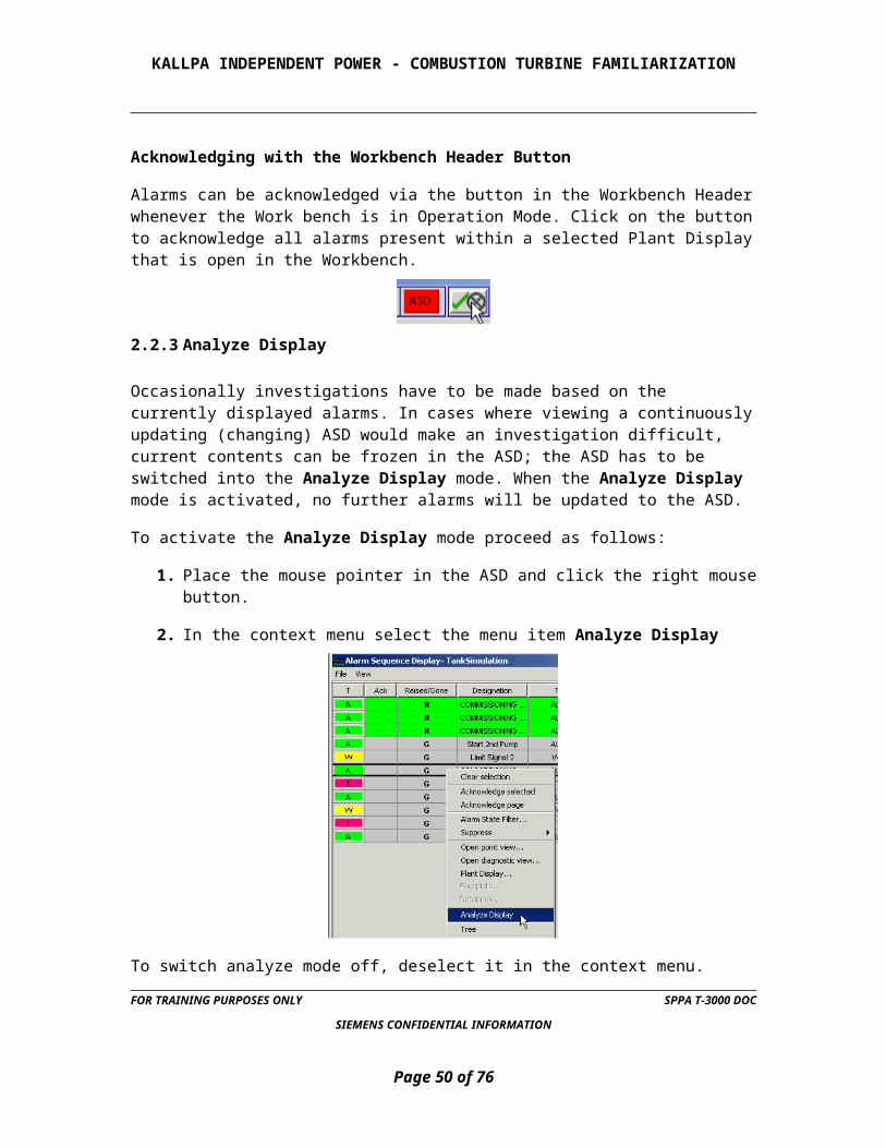
Acknowledging with the Workbench Header Button
Alarms can be acknowledged via the button in the Workbench Header whenever the Work bench is in Operation Mode. Click on the button to acknowledge all alarms present within a selected Plant Display that is open in the Workbench.
FOR TRAINING PURPOSES ONLY SPPA T-3000 DOC
SIEMENS CONFIDENTIAL INFORMATION
Page 35 of 58

KALLPA INDEPENDENT POWER - COMBUSTION TURBINE FAMILIARIZATION
2.2.3 Analyze Display
Occasionally investigations have to be made based on the currently displayed alarms. In cases where viewing a continuously updating (changing) ASD would make an investigation difficult, current contents can be frozen in the ASD; the ASD has to be switched into the Analyze Display mode. When the Analyze Display mode is activated, no further alarms will be updated to the ASD.
To activate the Analyze Display mode proceed as follows:
1. Place the mouse pointer in the ASD and click the right mouse button.
2. In the context menu select the menu item Analyze Display
To switch analyze mode off, deselect it in the context menu.
What will happen in Analyze Mode?
When analyze mode is switched on the following will occur:
No new alarms will be added to, or leave the List view.
The alarms present in the List View will continue to be updated.
Should a new alarm arrive, the user is informed by a message in the ASD status bar.
FOR TRAINING PURPOSES ONLY SPPA T-3000 DOC
SIEMENS CONFIDENTIAL INFORMATION
Page 36 of 58

KALLPA INDEPENDENT POWER - COMBUSTION TURBINE FAMILIARIZATION
2.2.4 Filtering of Alarms
To define a personal selection of events which occur, user specific Alarm Sequence Displays may be defined.
1. From the workbench select the menu Applications, then Alarm Sequence Display.
2. From the sub-items select New Alarm Sequence Display
3. In the pop-up menu enter a name for the user defined ASD and confirm with Ok or abort with Cancel
4. The user defined ASD appears in the list below the default ASD
Filtering of alarms is only possible for user defined ASD's.
2.2.4.1 How to Filter Alarm Types for Display
To select alarms for display in an ASD from the Project Hierarchy, proceed as follows:
A user defined ASD is open.
1. Unless existing switch on the Tree View.
FOR TRAINING PURPOSES ONLY SPPA T-3000 DOC
SIEMENS CONFIDENTIAL INFORMATION
Page 37 of 58

KALLPA INDEPENDENT POWER - COMBUSTION TURBINE FAMILIARIZATION
2. Select the node from which alarms will be displayed, by clicking on it.
3. With the cursor over the selected node, click the right mouse button to open the context menu.
4. Select Selection from the context menu.
5. The Selection dialog box will open.
FOR TRAINING PURPOSES ONLY SPPA T-3000 DOC
SIEMENS CONFIDENTIAL INFORMATION
Page 38 of 58

KALLPA INDEPENDENT POWER - COMBUSTION TURBINE FAMILIARIZATION
6. The Alarm Types are listed, and can be selected or deselected in the dialog box.
To select or deselect an Alarm Type for display, simply click on the tick box next to the Alarm Type.
An Alarm Type that is selected is represented by a tick. Deselected Alarm Types have no tick.
To select or deselect all Alarm Types click on the tick box next to Alarm Types at the top of the list.
7. If the node contains sub-nodes, the Include contained alarm groups tick box may be selected. When this tick box is ticked, the selection made will apply to all sub-nodes.
8. Click on Ok to accept the selection made, otherwise click on Cancel.
The ASD will display the selected Alarm Types.
2.2.4.2 How to Filter Alarm States for Display
The alarms in the ASD List View can be filtered according to alarm status, and acknowledgement state. This is very useful if, for instance, the user wishes to view all raised alarms in one ASD, and all gone alarms in another.
Three filter criteria are possible:
Raised and unacknowledged
Raised and acknowledged
Gone
FOR TRAINING PURPOSES ONLY SPPA T-3000 DOC
SIEMENS CONFIDENTIAL INFORMATION
Page 39 of 58

KALLPA INDEPENDENT POWER - COMBUSTION TURBINE FAMILIARIZATION
Any combination of the filter criteria may be used (e.g. the user may view Gone alarms only, or both Gone and Raised and unacknowledged simultaneously).
To set the alarm state filtering for a user defined ASD, proceed as follows:
1. A user defined ASD is open.
2. With the cursor anywhere in the List View click the right mouse button to open the context menu.
3. Select Alarm State Filter from the context menu.
4. The Alarm State Filter dialog box will open.
5. Make the selection for the filtering, by clicking in the checkboxes.
6. Click on Ok to apply the filtering criteria, otherwise click on Cancel.
The ASD will display the selected Alarm States.
2.2.4.3 How the Filtering is Indicated
The alarm display selection is indicated in the Tree View of the ASD.
If all alarms of all alarm types are selected for a node (and its sub-nodes), a black tick will appear next to the node in the Tree View.
If some of the alarms and/or some of the alarm types are selected for a node (and its sub-nodes), a gray tick will appear next to the node in the Tree View.
FOR TRAINING PURPOSES ONLY SPPA T-3000 DOC
SIEMENS CONFIDENTIAL INFORMATION
Page 40 of 58

KALLPA INDEPENDENT POWER - COMBUSTION TURBINE FAMILIARIZATION
If none of the alarms of any Alarm Type are selected for a node (and its sub-nodes), no tick will appear next to the node in the Tree View.
2.2.5 Automatic Acknowledging of Alarms
For user defined ASD's it is possible to acknowledge a selection of alarms automatically.
1. A user defined ASD is open.
1. Unless existing switch on the Tree View.
2. Select the node from which alarms will be displayed, by clicking on it.
3. With the cursor over the selected node, click the right mouse button to open the context menu.
4. Select Auto Acknowledgement from the context menu.
5. The Automatic Acknowledgement dialog box will open.
FOR TRAINING PURPOSES ONLY SPPA T-3000 DOC
SIEMENS CONFIDENTIAL INFORMATION
Page 41 of 58

KALLPA INDEPENDENT POWER - COMBUSTION TURBINE FAMILIARIZATION
6. The Alarm Types are listed, and can be selected or deselected in the dialog box.
7. If the node contains sub-nodes, the Include contained alarm groups tick box may be selected. When this tick box is ticked, the selection made will apply to all sub-nodes.
8. Click on Ok to accept the selection made, otherwise click on Cancel.
2.3 WORKING WITH TREND DISPLAYS
Trend displays are used to display the time-based variation of values as a curve. Measured process values, as well as results of calculations (e.g. performance calculations) can be displayed.
The trend display in SPPA-T3000 allows changing the time base in a wide range up to 24 hours per Display area, adding additional reading lines, up to 10 signals can be freely configured per trend display. Below find an example of a trend display.
2.3.1 Opening Trend Displays
In SPPA-T3000 trend displays are available from the Plant Display Hierarchy.
FOR TRAINING PURPOSES ONLY SPPA T-3000 DOC
SIEMENS CONFIDENTIAL INFORMATION
Page 42 of 58

KALLPA INDEPENDENT POWER - COMBUSTION TURBINE FAMILIARIZATION
To open a trend display
1. Select the icon of the trend display in the Plant Display Hierarchy,
2. Then click on the right mouse button and select Open Plant Display, or just double click the icon for the trend display
The trend display will be opened in a separate window in the workbench.
2.3.2 Adjusting the Displayed Time Duration
Above the displaying area a list box is located on the right side.
1. Click on the arrow on the right side to open the list box
2. Select the desired duration for the display area (10 min., 1, 6, 12 or 24 hours).
3.
FOR TRAINING PURPOSES ONLY SPPA T-3000 DOC
SIEMENS CONFIDENTIAL INFORMATION
Page 43 of 58

KALLPA INDEPENDENT POWER - COMBUSTION TURBINE FAMILIARIZATION
2.3.3 Dynamic and Static Mode of the Trend Displays
The SPPA-T3000 trend display can be switched into a dynamic or a static mode.
In the dynamic mode the curves are updated cyclically. New values are added at the right end of the curve, the curve moves from the right end to the left end of the display area. In the static mode the displayed curve is frozen, i.e. it will not be updated cyclically. To activate the static mode press the PAUSE button below the display area.
In the static mode any sequence which occurred in the past can be shown in the display area, if the desired values are stored in the archive. To move the time line to past values use the arrow buttons at the left end below the display area.
The << arrows moves the time line the selected duration (time units settings) to the past
The < arrows move the time line one half the selected duration to the past. The date and time valid for the left end of the displayed area is indicated here.
To move the time line back to the present values use the arrow buttons at the right end below the display area.
The >> arrows moves the time line the selected duration (time units setting) to the present.
The > arrows move the time line one half the selected duration to the present. The date and time valid for the right end of the displayed area is indicated here.
FOR TRAINING PURPOSES ONLY SPPA T-3000 DOC
SIEMENS CONFIDENTIAL INFORMATION
Page 44 of 58

KALLPA INDEPENDENT POWER - COMBUSTION TURBINE FAMILIARIZATION
2.3.4 Reading the Values in the Trend Display
The value displayed in the signal area of the Trend display in the column LAST is the current value at the time displayed at the right limit of the display area.
To get the value of any point of the displayed curve, up to two additional cursors, which can be moved at any position in the display area, can be activated additionally.
To activate the cursors proceed as follows:
1. Press one of the cursor buttons below the display area
2. An additional date / time indication appears for each of the additional cursors. The background color of this indication corresponds to the color of the reading line.
3. Now the user can either
Click with the mouse on the cursor line (the line appearance changes to bold), press and hold the left mouse button and move it to another position in the display area and then release the button.
Or
Adjust the new position within the date / time indication.
FOR TRAINING PURPOSES ONLY SPPA T-3000 DOC
SIEMENS CONFIDENTIAL INFORMATION
Page 45 of 58

KALLPA INDEPENDENT POWER - COMBUSTION TURBINE FAMILIARIZATION
4. The value of the respective curve is displayed in the column CURSOR 1, respectively CURSOR 2 in the signal list below the display area, corresponding to position of the reading line.
The field between the two date / time indications of the reading line displays the duration between the lines.
2.3.5 Displaying Trends from the Archive
To support the user in retrieving historical data, values of measurements and events, these are stored in an archive. Some of the values to be stored are configurable, and other values are stored by default without further engineering activities.
Values which are stored in the archive can be displayed in a trend display at any time. To display a trend quickly for historical data, a calendar is available to adjust any date immediately.
FOR TRAINING PURPOSES ONLY SPPA T-3000 DOC
SIEMENS CONFIDENTIAL INFORMATION
Page 46 of 58

KALLPA INDEPENDENT POWER - COMBUSTION TURBINE FAMILIARIZATION
To open the calendar proceed as follows
1. Click on the colored field (e.g. blue) next to a tag name of the trend which is to be displayed. The configuration dialog will open...
2. Select the Time tab.
If a check is applied for the setting Dynamic Trends in the lower part of this section, remove it by clicking this field. This enables the subsection Time Scope for changing the settings.
3. Open the calendar sheet by clicking the button at the right of the date field.
FOR TRAINING PURPOSES ONLY SPPA T-3000 DOC
SIEMENS CONFIDENTIAL INFORMATION
Page 47 of 58

KALLPA INDEPENDENT POWER - COMBUSTION TURBINE FAMILIARIZATION
4. Adjust the year, the month and the date as desired.
5. The upper list field allows the adjustment of the starting time, hours, minutes and seconds.
6. Finalize the setting with the button OK or abort with Cancel.
7. Press the button Apply to accept the settings or press the button Cancel to abort the changes. The button OK confirms the changes which have been made and closes the dialog immediately.
8. After the configuration dialog is closed, the desired trend beginning with the adjusted date and time is displayed.
2.3.6 Activation of the Optional Scales
When a trend display is open a scale in percentage units is available on the right of the display area by default. Scales in engineering units, as defined during the engineering view, can be optionally displayed left of the display area. To choose additional scales proceed as follows:
Press the button in the bottom toolbar to display buttons for each trend point scale
The buttons Y1 to Y10 correspond to the respective signal in the signal list.
1. Select the desired scales by pressing the corresponding button. The scales will be FOR TRAINING PURPOSES ONLY SPPA T-3000 DOC
SIEMENS CONFIDENTIAL INFORMATION
Page 48 of 58

KALLPA INDEPENDENT POWER - COMBUSTION TURBINE FAMILIARIZATION
added in the sequence as the buttons are pressed. A new scale is added to the left of any scales which have already been selected. To remove a scale press the corresponding button again.
2. After all desired scales are added press the button again to reset the toolbar.
3. A mark in a color corresponding to the color of the reading line shows the current value at the reading position.
2.3.7 Add and Remove Signals from a Trend Display
If it is necessary to add or remove a trend signal temporarily from the trend display proceed as follows: Remove a Signal
1. To remove a signal from the signal list press on the colored button next to the signal to open the configuration dialog
2. Delete the listed Tag Name by pressing the button Del.
3. Press the button Apply to accept the changes or press the button Cancel to abort the changes.
4. The button OK confirms the changes which have been made and closes the FOR TRAINING PURPOSES ONLY SPPA T-3000 DOC
SIEMENS CONFIDENTIAL INFORMATION
Page 49 of 58
KALLPA INDEPENDENT POWER - COMBUSTION TURBINE FAMILIARIZATION
dialog immediately.
Add a Signal
1. To add a signal in the signal list press on the colored button next to an empty row of the signal list to open the configuration dialog
2. To assign the new Tag name press the Search button
FOR TRAINING PURPOSES ONLY SPPA T-3000 DOC
SIEMENS CONFIDENTIAL INFORMATION
Page 50 of 58
Delete
Search

KALLPA INDEPENDENT POWER - COMBUSTION TURBINE FAMILIARIZATION
2.4 CONFIGURING AND VIEWING REPORTS
1. To generate a report the workbench needs to be opened.
2. From the menu item Applications select the sub item Reports.
3. The Report View will open.
4. Click on File.
FOR TRAINING PURPOSES ONLY SPPA T-3000 DOC
SIEMENS CONFIDENTIAL INFORMATION
Page 51 of 58

KALLPA INDEPENDENT POWER - COMBUSTION TURBINE FAMILIARIZATION
A drop down menu will appear with the following options:
Create Report opens the report definition form based on an existing report type. The definition will be opened without any items pre selected (as for create on demand reports).
Design Report opens a graphical report designer. The report designer has a tool bar to edit report elements or to create new elements. Additionally report elements can be selected to be moved inside their band or to be edited.
Report Archive Explorer opens the report archive explorer. In the report archive generated report files and related information contained in the associated report definition are stored. Event triggered and scheduled reports are always stored in the report archive.
2.4.1 Report Types
A Sequence Report lists the selected events in a chronological order
A Status Report lists the selected events with a certain aspect, e.g. the condition of certain signals at a moment.
After this decision has been made:
1. Click on the desired report type e.g. Operation Sequence.
2. Afterwards the corresponding configuration window will appear.
FOR TRAINING PURPOSES ONLY SPPA T-3000 DOC
SIEMENS CONFIDENTIAL INFORMATION
Page 52 of 58

KALLPA INDEPENDENT POWER - COMBUSTION TURBINE FAMILIARIZATION
2.4.2 Adjusting Date and Time Range (From/To).
1. After a click on the calendar arrow icon on the right hand side of the date field a calendar sheet pops up with the current date.
2. In the appearing calendar sheet select the desired starting date for the query.
3. Click on calendar arrow icon again to save the desired values.
4. After a click on the time arrow icon on the right hand side of the time field a time sheet pops up.
5. Click on the arrow up or down on the right side to change the hours, minutes, seconds, milliseconds and time of day.
6. Click on the time arrow icon again to save the desired values.
7. Perform the same actions for the To section.
Selection of certain tags to be included in the report If the query is to be limited to a subset of records and does not require all available records (as defined in the time window), the selection of the subset has to be specified in the field Tags.
FOR TRAINING PURPOSES ONLY SPPA T-3000 DOC
SIEMENS CONFIDENTIAL INFORMATION
Page 53 of 58

KALLPA INDEPENDENT POWER - COMBUSTION TURBINE FAMILIARIZATION
2.4.3 Specify a selection of signals:
1. The entered expression is not case sensitive, i.e. bba will have the same result as BBA or bBa.
2. The signal separator, as defined in the project setting has to be included if applicable.
3. Wildcards, to replace one or more characters, are allowed. Characters in this meaning include letters (a..z, A..Z,) or numbers (0, 1..9), underscores and dashes ("_", "-").
4. Other characters as mentioned above and blanks in the tags should not be used in tag names to ensure unique identifiers.
5. A question mark "?" represents one character.
6. E.g. a search string like BB?10 will select all tags which have a length of 5 characters, and begin with "BB" (or "bb", ...), and end with "10", irrespective of the character between them. A sequence of two or more question marks will replace the corresponding number of characters.
7. An asterisk "*" replaces an unspecified number of characters. E.g. a search string like BB*10 will select all tags which
8. -begin with "BB" (or "bb", ...), and end with "10", irrespective of the character(s) and number of characters between them. A search string like BBA10* will select all tags which start with "BBA10". A search string like *CL001 will select all tags which end with "CL001".
9. Merging of different tags in one report can be achieved by entering more than one search string, separated by a comma ",".
10. E.g. the search string BBA*CE*, LBA*CT* will select all tags which match to "BBA*CE*" and all tags which match to "LBA*CT*"
FOR TRAINING PURPOSES ONLY SPPA T-3000 DOC
SIEMENS CONFIDENTIAL INFORMATION
Page 54 of 58

KALLPA INDEPENDENT POWER - COMBUSTION TURBINE FAMILIARIZATION
11. A fully specified tag in SPPA-T3000 consists of 3 parts. In the parameter list of the Automation Function Blocks these 3 parts are called Tag Name, Signal Item and Signal Name. In principle each of these parts is optional. However, the operators need a unique tag to identify a certain function.
Even if one of these parts is not used, the signal separator, as preset in the project settings, will appear in any reported line.
For an unlimited selection, enter an asterisk "*"into the field Tags.
2.4.4 Other settings:
Set a filter on records with a specific Quality Code
The section Quality contains the Quality Codes which are stored with the event records in the archive. A filter can be set on a selection of these quality codes. The dialog element for Quality Code consists of two list boxes containing the selected and unselected Quality Code. Select the desired Quality Code in the available list field, click on the button <Add and the Quality code will be displayed in the selected field. - To select more than one Quality Code repeat this procedure. - To select all Quality Codes, click on some one in the available field and then the button <<Add all. - To remove one Quality Code, select the desired Quality Code in the selected field, click on the button Remove> and the Quality Code will be deselected. - To remove all Quality Codes, click on some one in the selected field and then the button Remove all>>. All selected Quality Codes will be deselected.
FOR TRAINING PURPOSES ONLY SPPA T-3000 DOC
SIEMENS CONFIDENTIAL INFORMATION
Page 55 of 58

KALLPA INDEPENDENT POWER - COMBUSTION TURBINE FAMILIARIZATION
2.4.4.1 Set a filter on records with a specific User
The section User contains the user IDs which are related to the events stored in the archive. A selection of the user ID can be used to generate a report which includes events caused by a certain user. To select Users perform the same actions as described above.
Set a filter on records with a specific alarm type
The section Types contains all alarm types which are stored with the event records in the archive. A filter can be set on a selection of these alarm types. To select Alarm Types perform the same actions as described above.
2.4.4.2 Set a filter on records with a specific alarm state
The section Alarm state contains all alarm states which are stored with the event records in the archive. A filter can be set on a selection of these alarm states.
2.4.4.3 Set a filter on records with a specific Binary Value
The section Binary Value contains all binary values which are stored with the event records in the archive. A filter can be set on a selection of these binary values
When all settings are finished click the button Create Report.
FOR TRAINING PURPOSES ONLY SPPA T-3000 DOC
SIEMENS CONFIDENTIAL INFORMATION
Page 56 of 58

KALLPA INDEPENDENT POWER - COMBUSTION TURBINE FAMILIARIZATION
For the report a PDF file is created. To read this file an appropriate viewer, e.g. Adobe Acrobat Reader, has to be installed at the operator station. By default the report is opened immediately after preparation in a new window at the operator station.
Further options for Report handling can be select on the Output sheet.
An example is shown below for an Alarm Sequence Report related to the Getting Started section.
FOR TRAINING PURPOSES ONLY SPPA T-3000 DOC
SIEMENS CONFIDENTIAL INFORMATION
Page 57 of 58

KALLPA INDEPENDENT POWER - COMBUSTION TURBINE FAMILIARIZATION
FOR TRAINING PURPOSES ONLY SPPA T-3000 DOC
SIEMENS CONFIDENTIAL INFORMATION
Page 58 of 58