Embed Size (px)
Citation preview
15-122 Assignment 1 Page 1 of 12
15-122 : Principles of Imperative Computation
Fall 2012
Assignment 1: Image Manipulation - UPDATE 1
(Programming Part)
Due: Thursday, September 13, 2012 by 23:59
For the programming portion of this week’s homework, you’ll review how images are storedin the computer using C0 (described in Section 1.1), and then you’ll write four C0 files:imageutil.c0 (described in Section 1.2), invert.c0 (described in Section 1.3), reflect.c0(described in Section 1.4), and mask.c0 (described in Section 1.5). You’ll also have anopportunity to design your own image processing function (described in Section 1.6).
You should submit your code electronically by 11:59 pm on the due date. Detailed submissioninstructions can be found below.
15-122 Assignment 1 Page 2 of 12
1 Assignment: Image Manipulation (25 points)
Starter code. Download the file handout-hw1.tar from the course website or Autolab.When you unpack it, you will find a number of files.
Four of the files are imageutil.c0, invert.c0, reflect.c0, and mask.c0, which arewhere you will write your solution to the required image manipulation problems below.These four files are the only files that you should submit for these problems. Note that youshould not write a main() function in any of these files. You will also see several *-main.c0files, which contain the main() functions for each task. These can be used to compile andtest your code. Finally, there is manipulate.c0 and manipulate-main.c0, for the optionalmanipulation described in Section 1.6.
In addition, you will find a sample manipulation remove-red.c0, which removes the redchannel from each pixel of an image, and its associated main file remove-red-main.c0. Thissample provides a complete program that you can compile and execute, and you may patternyour code after the code in remove-red.c0 if you find it convenient to do so. (The code forthe remove red function also appears in Appendix A.)
Finally, you will also see an images/ directory with some sample input images andsome sample outputs for some of the manipulations. On a Linux cluster machine, there areseveral programs you can use to view the images, including display, gpicview, qiv, eog,and gthumb. Play around and find one you like.
Compiling and running. To compile one of your completed exercises just specify thefile(s) on the command line in the order you want them compiled. You can compile yourfiles on any Andrew system by running the command
cc0 <file1>.c0 <file2>.c0 <file3>.c0 -o <executablefilename>
from the directory where your c0 files reside. This will will place the compiled binary in thefile <file> rather than the usual default a.out.
Once you’ve compiled <file> in this way, you can run it with the command
./<executablefilename>
The file so produced will expect some options of its own, at the very least an option -i
<input file> specifying the input image to manipulate. If you run one of the programswithout any arguments, you will get a short usage message explaining the options particularto that program.
As a concrete example, you can compile the remove-red filter with dynamic checkingand run it on the sample image g5.png in the images/ directory by running the followingcommands in sequence:
cc0 -d remove-red.c0 remove-red-main.c0 -o remove-red
./remove-red -i images/g5.png -o images/g5nored.png
If you have any problems compiling or running your code as described here, you shouldcontact the course staff.
15-122 Assignment 1 Page 3 of 12
Submitting. Once you’ve completed some files, you can submit them to Autolab. Thereare two ways to do this:
From the terminal on Andrew Linux (via cluster or ssh) type:
handin hw1 imageutil.c0 invert.c0 reflect.c0 mask.c0 manipulate.c0
Your score will then be available on the Autolab website.
Your files can also be submitted to the web interface of Autolab. To do so, please tar
them, for example:
tar -cvf hw1_solutions.tar imageutil.c0 invert.c0 reflect.c0 mask.c0 manipulate.c0
Then, go to https://autolab.cs.cmu.edu/15122-f12 and submit them as your solu-tion to homework 1.
You can submit files as many times as you like. When we grade your assignment, we willconsider the most recent version submitted before the due date. If you get any errors whiletrying to submit your code, you should contact the course staff immediately.
Testing. You are encouraged to use the provided *-main.c0 files to help you test yourcode. Feel free to write additional testing code of your own before submitting to Autolab–don’t rely on the grader’s output for debugging. For this assignment, we are providing aprogram, imagediff to help you compare your output images to the sample images in thehandout, optionally saving an image that shows you exactly where the two images differ. Itis in the course directory on afs, so it is available on any cluster machine or when you areconnected via ssh. For example:
imagediff -i images/sample-image.png -j images/my-image.png -o images/diff.png
Annotations. Be sure to include //@requires, //@ensures, and //@loop invariant
annotations in your program. You should write these as you are writing the code ratherthan after you’re done: documenting your code as you go along will help you reason aboutwhat it should be doing, and thus help you write code that is both clearer and more correct.Proper use of annotations will be tested by Autolab and may be considered in the stylegrade.
Style. Strive to write code with good style: indent every line of a block to the same level,use descriptive variable names, keep lines to 80 characters or fewer, document your codewith comments, etc. If you find yourself writing the same code over and over, you shouldwrite a separate function to handle that computation and call it whenever you need it. Wewill read your code when we grade it, and good style is sure to earn our good graces. Feelfree to ask on Piazza if you’re unsure of what constitutes good style.
Task 0 (5 points) 5 points on this assignment will be given for style.
15-122 Assignment 1 Page 4 of 12
1.1 Image Manipulation Overview
The three short programming problems you have for this assignment deal with manipulatingimages. An image will be stored in a one-dimensional array of integers, where each integeris a 32-bit value representing one pixel of the image. Pixels are stored in the array row byrow, left to right starting at the top left of the image. For example, if a 5 × 5 image has thefollowing pixel “values”:
a b c d ef g h i jk l m n op q r s tu v w x y
then these values would be stored in the array in this order:
a b c d e f g h i j k l m n o p q r s t u v w x y
In the 5× 5 image, the pixel i is in row 1, column 3 (rows and columns are indexed startingwith 0) but is stored in the one-dimensional array at index 8. An image must have at leastone pixel.
Each pixel in the array is a 32-bit integer that can be broken up into 4 components with8 bits each:
a0a1a2a3a4a5a6a7 r0r1r2r3r4r5r6r7 g0g1g2g3g4g5g6g7 b0b1b2b3b4b5b6b7
where:
a0a1a2a3a4a5a6a7 represents the alpha value (how opaque the pixel is)r0r1r2r3r4r5r6r7 represents the intensity of the red component of the pixelg0g1g2g3g4g5g6g7 represents the intensity of the green component of the pixelb0b1b2b3b4b5b6b7 represents the intensity of the blue component of the pixel
Each 8-bit component can range between a minimum of 0 (binary 00000000 or hex 0x00) toa maximum of 255 (binary 11111111 or hex 0xFF).
For example, a pixel that is completely opaque with only green at its maximum intensitywould be stored as the integer 0xFF00FF00. An opaque pixel that is medium gray wouldbe 0xFF7F7F7F (equal parts red, green, and blue at medium intensity).
For the rest of the assignment, we will work under the assumption of a type definitionthat makes pixel an alias for int:
typedef int pixel;
Since ints are used for many other things (like the width and height of an image, forexample), a type alias is useful for distinguishing those instances where we mean to interpretan int as an RGB pixel. You should include this typedef in your code and use the pixel
type when appropriate.
15-122 Assignment 1 Page 5 of 12
1.2 Creating a set of Image Utility Functions
In this problem, you will complete the implementation of the functions specified in theimageutil.c0 file. This file contains functions that may be helpful for you in the subsequentproblems. The specification (expected input and output) for each function is written in acomment above the function declaration.
TASK 1 ( 5 pts.) Complete the C0 file imageutil.c0 that includes a number of helpfulimage utility functions. For each function, in addition to completing the code, write thestrongest precondition(s) and postcondition(s) (using requires and ensures). Includeadditional assertions and loop invariants as necessary. We will compile your program asfollows:
cc0 -d imageutil.c0 imageutil-main.c0
using your imageutil.c0 file. Your code must compile using these instructions with filesshown in the order given. [UPDATED] We did not distribute a imageutil-main.c0 file;you can check that imageutil.c0 compiles using coin. You are encouraged to write yourown imageutil-main.c0 file that tests imageutil.c0. Do NOT include a main function inyour imageutil.c0 file.
1.3 Selectively Inverting an Image
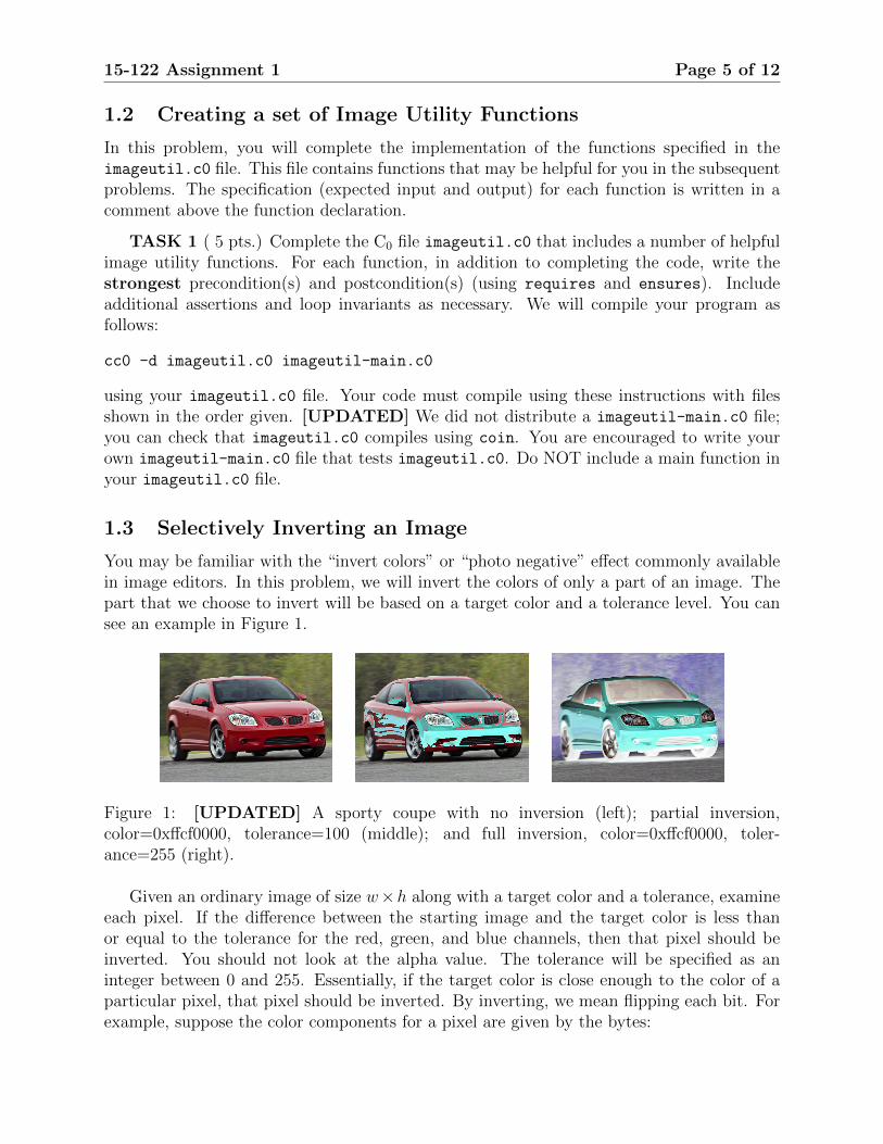
You may be familiar with the “invert colors” or “photo negative” effect commonly availablein image editors. In this problem, we will invert the colors of only a part of an image. Thepart that we choose to invert will be based on a target color and a tolerance level. You cansee an example in Figure 1.
Figure 1: [UPDATED] A sporty coupe with no inversion (left); partial inversion,color=0xffcf0000, tolerance=100 (middle); and full inversion, color=0xffcf0000, toler-ance=255 (right).
Given an ordinary image of size w×h along with a target color and a tolerance, examineeach pixel. If the difference between the starting image and the target color is less thanor equal to the tolerance for the red, green, and blue channels, then that pixel should beinverted. You should not look at the alpha value. The tolerance will be specified as aninteger between 0 and 255. Essentially, if the target color is close enough to the color of aparticular pixel, that pixel should be inverted. By inverting, we mean flipping each bit. Forexample, suppose the color components for a pixel are given by the bytes:
15-122 Assignment 1 Page 6 of 12
COLOR RED GREEN BLUE
BINARY 01111101 10100001 10010111
DECIMAL 125 161 151
HEX 0x7d 0xa1 0x97
And our target color is:
COLOR RED GREEN BLUE
DECIMAL 143 178 158
HEX 0x8f 0xb5 0x9e
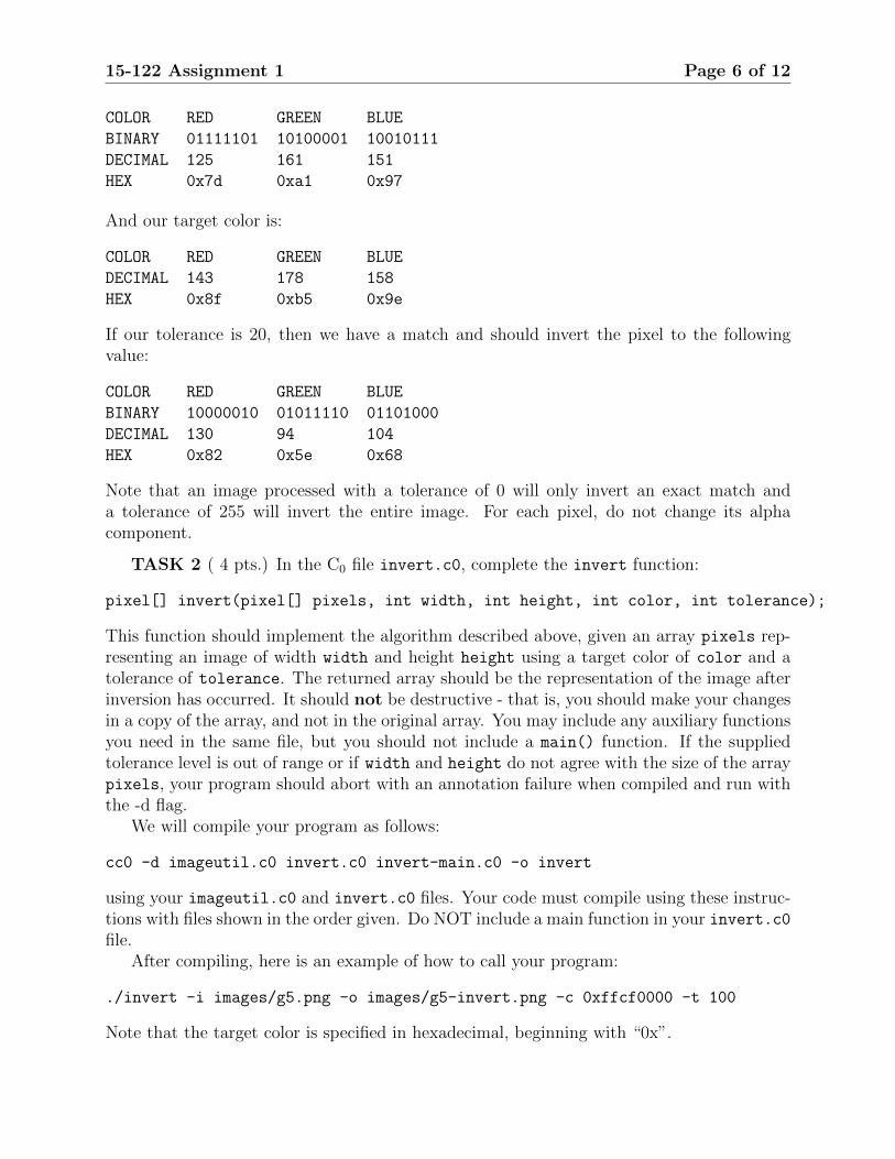
If our tolerance is 20, then we have a match and should invert the pixel to the followingvalue:
COLOR RED GREEN BLUE
BINARY 10000010 01011110 01101000
DECIMAL 130 94 104
HEX 0x82 0x5e 0x68
Note that an image processed with a tolerance of 0 will only invert an exact match anda tolerance of 255 will invert the entire image. For each pixel, do not change its alphacomponent.
TASK 2 ( 4 pts.) In the C0 file invert.c0, complete the invert function:
pixel[] invert(pixel[] pixels, int width, int height, int color, int tolerance);
This function should implement the algorithm described above, given an array pixels rep-resenting an image of width width and height height using a target color of color and atolerance of tolerance. The returned array should be the representation of the image afterinversion has occurred. It should not be destructive - that is, you should make your changesin a copy of the array, and not in the original array. You may include any auxiliary functionsyou need in the same file, but you should not include a main() function. If the suppliedtolerance level is out of range or if width and height do not agree with the size of the arraypixels, your program should abort with an annotation failure when compiled and run withthe -d flag.
We will compile your program as follows:
cc0 -d imageutil.c0 invert.c0 invert-main.c0 -o invert
using your imageutil.c0 and invert.c0 files. Your code must compile using these instruc-tions with files shown in the order given. Do NOT include a main function in your invert.c0file.
After compiling, here is an example of how to call your program:
./invert -i images/g5.png -o images/g5-invert.png -c 0xffcf0000 -t 100
Note that the target color is specified in hexadecimal, beginning with “0x”.
15-122 Assignment 1 Page 7 of 12
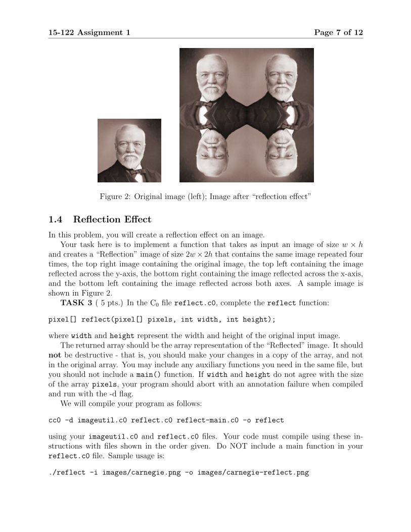
Figure 2: Original image (left); Image after “reflection effect”
1.4 Reflection Effect
In this problem, you will create a reflection effect on an image.Your task here is to implement a function that takes as input an image of size w × h
and creates a “Reflection” image of size 2w× 2h that contains the same image repeated fourtimes, the top right image containing the original image, the top left containing the imagereflected across the y-axis, the bottom right containing the image reflected across the x-axis,and the bottom left containing the image reflected across both axes. A sample image isshown in Figure 2.
TASK 3 ( 5 pts.) In the C0 file reflect.c0, complete the reflect function:
pixel[] reflect(pixel[] pixels, int width, int height);
where width and height represent the width and height of the original input image.The returned array should be the array representation of the “Reflected” image. It should
not be destructive - that is, you should make your changes in a copy of the array, and notin the original array. You may include any auxiliary functions you need in the same file, butyou should not include a main() function. If width and height do not agree with the sizeof the array pixels, your program should abort with an annotation failure when compiledand run with the -d flag.
We will compile your program as follows:
cc0 -d imageutil.c0 reflect.c0 reflect-main.c0 -o reflect
using your imageutil.c0 and reflect.c0 files. Your code must compile using these in-structions with files shown in the order given. Do NOT include a main function in yourreflect.c0 file. Sample usage is:
./reflect -i images/carnegie.png -o images/carnegie-reflect.png
15-122 Assignment 1 Page 8 of 12
1.5 Applying Masks to an Image
In this problem, you will write a function that will apply a “mask” to an image. A maskis an n × n array of integers representing weights. For our purposes, n must be odd. Theorigin of the mask is its center position. For each pixel in the input image, think of themask as being placed on top of the image so its origin is on the pixel we wish to examine.The intensity value of each pixel under the mask is multiplied by the corresponding value inthe mask that covers it. These products are added together. Always use the original valuesfor each pixel for each mask calculation, not the new values you compute as you processthe image. Your function will return an array of integers the same size as the image, whichcontains the result of applying the mask.
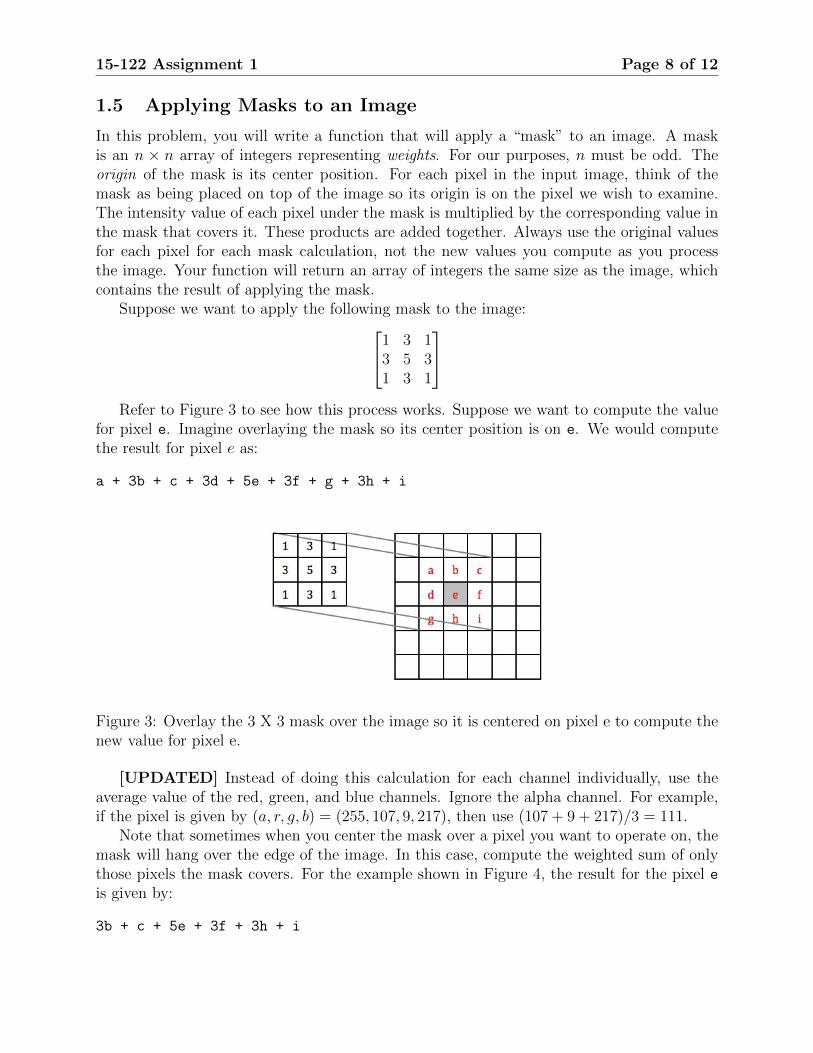
Suppose we want to apply the following mask to the image:1 3 13 5 31 3 1
Refer to Figure 3 to see how this process works. Suppose we want to compute the value
for pixel e. Imagine overlaying the mask so its center position is on e. We would computethe result for pixel e as:
a + 3b + c + 3d + 5e + 3f + g + 3h + i
Figure 3: Overlay the 3 X 3 mask over the image so it is centered on pixel e to compute thenew value for pixel e.
[UPDATED] Instead of doing this calculation for each channel individually, use theaverage value of the red, green, and blue channels. Ignore the alpha channel. For example,if the pixel is given by (a, r, g, b) = (255, 107, 9, 217), then use (107 + 9 + 217)/3 = 111.
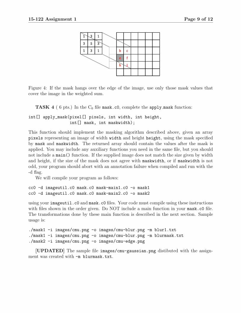
Note that sometimes when you center the mask over a pixel you want to operate on, themask will hang over the edge of the image. In this case, compute the weighted sum of onlythose pixels the mask covers. For the example shown in Figure 4, the result for the pixel eis given by:
3b + c + 5e + 3f + 3h + i
15-122 Assignment 1 Page 9 of 12
Figure 4: If the mask hangs over the edge of the image, use only those mask values thatcover the image in the weighted sum.
TASK 4 ( 6 pts.) In the C0 file mask.c0, complete the apply mask function:
int[] apply_mask(pixel[] pixels, int width, int height,
int[] mask, int maskwidth);
This function should implement the masking algorithm described above, given an arraypixels representing an image of width width and height height, using the mask specifiedby mask and maskwidth. The returned array should contain the values after the mask isapplied. You may include any auxiliary functions you need in the same file, but you shouldnot include a main() function. If the supplied image does not match the size given by widthand height, if the size of the mask does not agree with maskwidth, or if maskwidth is notodd, your program should abort with an annotation failure when compiled and run with the-d flag.
We will compile your program as follows:
cc0 -d imageutil.c0 mask.c0 mask-main1.c0 -o mask1
cc0 -d imageutil.c0 mask.c0 mask-main2.c0 -o mask2
using your imageutil.c0 and mask.c0 files. Your code must compile using these instructionswith files shown in the order given. Do NOT include a main function in your mask.c0 file.The transformations done by these main function is described in the next section. Sampleusage is:
./mask1 -i images/cmu.png -o images/cmu-blur.png -m blur1.txt
./mask1 -i images/cmu.png -o images/cmu-blur.png -m blurmask.txt
./mask2 -i images/cmu.png -o images/cmu-edge.png
[UPDATED] The sample file images/cmu-gaussian.png distibuted with the assign-ment was created with -m blurmask.txt.
15-122 Assignment 1 Page 10 of 12
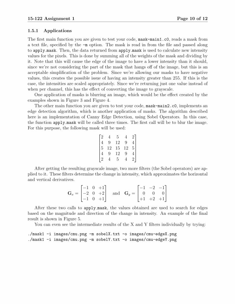
1.5.1 Applications
The first main function you are given to test your code, mask-main1.c0, reads a mask froma text file, specified by the -m option. The mask is read in from the file and passed alongto apply mask. Then, the data returned from apply mask is used to calculate new intensityvalues for the pixels. This is done by summing all of the weights of the mask and dividing byit. Note that this will cause the edge of the image to have a lower intensity than it should,since we’re not considering the part of the mask that hangs off of the image, but this is anacceptable simplification of the problem. Since we’re allowing our masks to have negativevalues, this creates the possible issue of having an intensity greater than 255. If this is thecase, the intensities are scaled appropriately. Since we’re returning just one value instead ofwhen per channel, this has the effect of converting the image to grayscale.
One application of masks is blurring an image, which would be the effect created by theexamples shown in Figure 3 and Figure 4.
The other main function you are given to test your code, mask-main2.c0, implements anedge detection algorithm, which is another application of masks. The algorithm describedhere is an implementation of Canny Edge Detection, using Sobel Operators. In this case,the function apply mask will be called three times. The first call will be to blur the image.For this purpose, the following mask will be used:
2 4 5 4 24 9 12 9 45 12 15 12 54 9 12 9 42 4 5 4 2
After getting the resulting grayscale image, two more filters (the Sobel operators) are ap-
plied to it. These filters determine the change in intensity, which approximates the horizontaland vertical derivatives.
Gx =
−1 0 +1−2 0 +2−1 0 +1
and Gy =
−1 −2 −10 0 0
+1 +2 +1
After these two calls to apply mask, the values obtained are used to search for edges
based on the magnitude and direction of the change in intensity. An example of the finalresult is shown in Figure 5.
You can even see the intermediate results of the X and Y filters individually by trying:
./mask1 -i images/cmu.png -m sobelX.txt -o images/cmu-edgeX.png
./mask1 -i images/cmu.png -m sobelY.txt -o images/cmu-edgeY.png
15-122 Assignment 1 Page 11 of 12
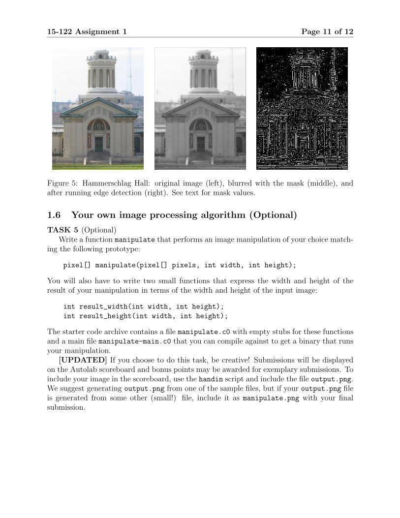
Figure 5: Hammerschlag Hall: original image (left), blurred with the mask (middle), andafter running edge detection (right). See text for mask values.
1.6 Your own image processing algorithm (Optional)
TASK 5 (Optional)Write a function manipulate that performs an image manipulation of your choice match-
ing the following prototype:
pixel[] manipulate(pixel[] pixels, int width, int height);
You will also have to write two small functions that express the width and height of theresult of your manipulation in terms of the width and height of the input image:
int result_width(int width, int height);
int result_height(int width, int height);
The starter code archive contains a file manipulate.c0 with empty stubs for these functionsand a main file manipulate-main.c0 that you can compile against to get a binary that runsyour manipulation.
[UPDATED] If you choose to do this task, be creative! Submissions will be displayedon the Autolab scoreboard and bonus points may be awarded for exemplary submissions. Toinclude your image in the scoreboard, use the handin script and include the file output.png.We suggest generating output.png from one of the sample files, but if your output.png fileis generated from some other (small!) file, include it as manipulate.png with your finalsubmission.
15-122 Assignment 1 Page 12 of 12
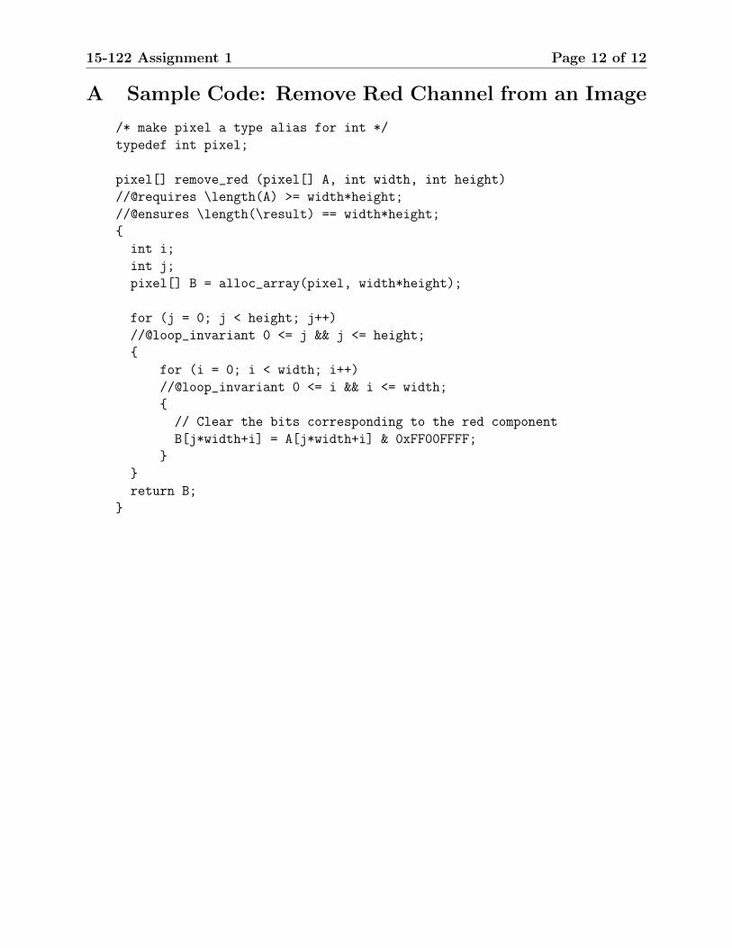
A Sample Code: Remove Red Channel from an Image
/* make pixel a type alias for int */
typedef int pixel;
pixel[] remove_red (pixel[] A, int width, int height)
//@requires \length(A) >= width*height;
//@ensures \length(\result) == width*height;
{
int i;
int j;
pixel[] B = alloc_array(pixel, width*height);
for (j = 0; j < height; j++)
//@loop_invariant 0 <= j && j <= height;
{
for (i = 0; i < width; i++)
//@loop_invariant 0 <= i && i <= width;
{
// Clear the bits corresponding to the red component
B[j*width+i] = A[j*width+i] & 0xFF00FFFF;
}
}
return B;
}