Embed Size (px)
Citation preview

7/27/2019 145391 ADS 50-5 Operating Instructions En
http://slidepdf.com/reader/full/145391-ads-50-5-operating-instructions-en 1/14
maxon motormaxon motor control 4-Q-DC Servoamplifier ADS 50/5
Order number 145391
Operating Instructions July 2009 Edition
The ADS 50/5 is a powerful servoamplifier fordriving permanent magnet DC motors up to250 Watts.Four modes can be selected by DIP switcheson the board:
• Speed control using tacho signals
• Speed control using encoder signals
• IxR compensated speed control
• Torque or current control
The ADS 50/5 is protected against excess
current,excess temperature and short circuit on themotor winding. With the FET power transis-tors incorporated in the servoamplifier, anefficiency of up to 95 % is achieved. A built inmotor choke combined with the high PWMfrequency of 50 kHz allows the connection ofmotors with a very low inductivity. In mostcases an external choke can be omitted.Thanks to the wide input power supply range of 12 - 50 VDC, the ADS 50/5 is very versatile and can be usedwith various power supplies. The aluminium housing makes installation simple, with terminal markings for easyconnection.
Table of Contents
1 Safety Instructions ...........................................................................................................................................2 2 Performance Data............................................................................................................................................3 3 Minimum External Wiring for Different Modes of Operation ............................................................................4 4 Operating Instructions......................................................................................................................................5
5 Functions .........................................................................................................................................................7 6 Additional Possible Adjustments....................................................................................................................10 7 Operating Status Display...............................................................................................................................12 8 Error Handling................................................................................................................................................13 9 EMC-compliant installation ............................................................................................................................13 10 Block Diagram................................................................................................................................................14 11 Dimension Drawing........................................................................................................................................14
The latest edition of these operating instructions may be downloaded from the internet as a PDF-file underwww.maxonmotor.com, category «Service & Downloads», order number 145391 orin the e-shop http://shop.maxonmotor.com.
7/27/2019 145391 ADS 50-5 Operating Instructions En
http://slidepdf.com/reader/full/145391-ads-50-5-operating-instructions-en 2/14
maxon motor
4-Q-DC Servoamplifier ADS 50/5 Operating Instructions
2
1 Safety Instructions
Skilled PersonnelInstallation and starting of the equipment shall only be performed by experienced, skil-led personnel.
Statutory RegulationsThe user must ensure that the servoamplifier and the components belonging to it areassembled and connected according to local statutory regulations.
Load DisconnectedFor primary operation the motor should be free running, i.e. with the load disconnected.
Additional Safety Equipment An electronic apparatus is not fail-safe in principle. Machines and apparatus must the-re-fore be fitted with independent monitoring and safety equipment. If the equipment
breaks down, if it is operated incorrectly, if the control unit breaks down or if the cablesbreak, etc., it must be ensured that the drive or the complete apparatus is kept in a safeoperating mode.
RepairsRepairs may be made by authorised personnel only or by the manufacturer. It is dange-rous for the user to open the unit or make repairs to it.
DangerDo ensure that during the installation of the ADS 50/5 no apparatus is connected to theelectrical supply. After switching on, do not touch any live parts.
Max. Supply Voltage
Make sure that the supply voltage is between 12 and 50 VDC. Voltages higher than 53VDC or of wrong polarity will destroy the unit.
Short circuit and earth faultThe ADS 50/5 amplifier is not protected against winding short circuits against groundsafety earth or Gnd!
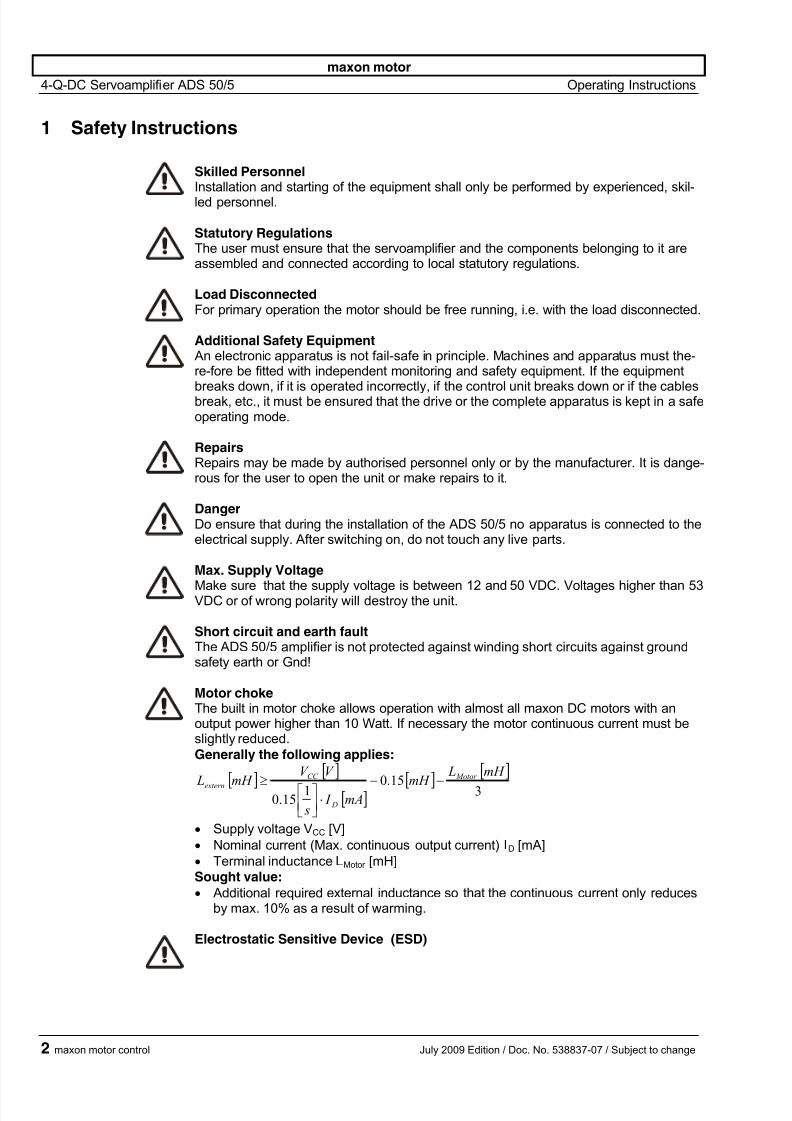
Motor chokeThe built in motor choke allows operation with almost all maxon DC motors with anoutput power higher than 10 Watt. If necessary the motor continuous current must beslightly reduced.
Generally the following applies:
[ ]
[ ]
[ ] [ ]
[ ]3
15.01
15.0
mH LmH
mA I s
V V mH L
Motor
D
CC
extern −−⋅⎥⎦⎤
⎢⎣⎡≥
• Supply voltage VCC [V]
• Nominal current (Max. continuous output current) ID [mA]
• Terminal inductance LMotor [mH]Sought value:
• Additional required external inductance so that the continuous current only reducesby max. 10% as a result of warming.
Electrostatic Sensitive Device (ESD)
maxon motor control July 2009 Edition / Doc. No. 538837-07 / Subject to change

7/27/2019 145391 ADS 50-5 Operating Instructions En
http://slidepdf.com/reader/full/145391-ads-50-5-operating-instructions-en 3/14
maxon motor
4-Q-DC Servoamplifier ADS 50/5 Operating Instructions
2 Performance Data
2.1 Electrical data
Nominal supply voltage +Vcc.....................................................................................12 … 50 VDC
Absolute minimum supply voltage +Vcc min ........................................................... ........... 11.4 VDC Absolute maximum supply voltage +Vcc max ......................................................... ........... 52.5 VDC
Max. output voltage ..................................................... ..................................................... 0.9 · VCC
Max. output current Imax ...................................................... .................................................... 10 A
Continuous output current Icont ..................................................... ............................................. 5 A
Switching frequency .............................................. ..................................................... ........ 50 kHz
Efficiency .................................................. .................................................... ......................... 95 %
Band width current controller ........................................................... .................................. 2.5 kHz
Built-in motor choke....................................................................................................150 µH / 5 A
2.2 Inputs
Set value ............................................................ .................................. -10 ... +10 V (Ri = 20 kΩ)
Enable ....................................................... ...................................... +4 ... + 50 VDC (Ri = 15 kΩ)
Input voltage DC tacho “Tacho Input”......... .................... min. 2 VDC, max. 50 VDC (Ri = 14 kΩ)
Encoder signals “Channel A, A\, B, B\”............. ....................................... max. 100 kHz, TTL level
2.3 Outputs
Current monitor “Monitor I”, short-circuit protected......................... -10 ...+10 VDC (RO = 100 Ω)
Speed monitor “Monitor n”, short-circuit protected.......................... -10 ...+10 VDC (RO = 100 Ω)
Status reading “READY”
Open collector, short-circuit protected ................................................ max. 30 VDC (IL ≤ 20 mA)
2.4 Voltage outputs
Aux. voltage, short-circuit protected ......................+12 VDC, -12 VDC, max. 12 mA (RO = 1 kΩ)
Encoder supply voltage .......................................................... ...................... +5 VDC, max. 80 mA
2.5 Trim potentiometers
IxR compensation
Offsetnmax
Imax
gain
2.6 LED indicator
2 coloured LED................... ........................................................ ....................... READY / ERROR
green = ok, red = error
2.7 Ambient temperature- / Humidity range
Operating..................................... ........................................................ ...................... -10 ... +45°C
Storage....................................................... ..................................................... .......... -40 ... +85°C
Non condensating........................................................ ................................................. 20 ... 80 %
2.8 Mechanical dataWeight .................................................. ....................................................... .............approx. 360 g
Dimensions......................................................... ....................................... see dimension drawing
Mounting plate................................................ ....................................................... .. for M4 screws
2.9 Terminal
PCB-clamps..............................................................................Power (5 poles), Signal (12 poles)
Pitch............................................................................................................................3.81 mm
suitable for wire cross section......................................0.14 - 1 mm2
multiple-stranded wire or
............................................... ....................................................... .. 0.14 - 1.5 mm2 single wire
Encoder .............................................. .................................................... ............... Plug DIN41651
for flat cable, pitch 1.27 mm, AWG 28
July 2009 Edition / Doc. No. 538837-07 / Subject to change maxon motor control 3
7/27/2019 145391 ADS 50-5 Operating Instructions En
http://slidepdf.com/reader/full/145391-ads-50-5-operating-instructions-en 4/14
maxon motor
4-Q-DC Servoamplifier ADS 50/5 Operating Instructions
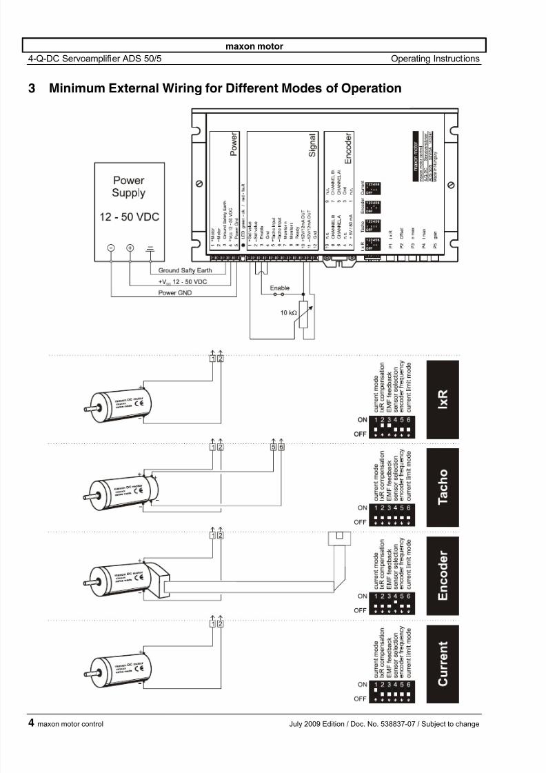
3 Minimum External Wiring for Different Modes of Operation
4 maxon motor control July 2009 Edition / Doc. No. 538837-07 / Subject to change

7/27/2019 145391 ADS 50-5 Operating Instructions En
http://slidepdf.com/reader/full/145391-ads-50-5-operating-instructions-en 5/14
maxon motor
4-Q-DC Servoamplifier ADS 50/5 Operating Instructions
4 Operating Instructions
4.1 Determine power supply requirements
You may make use of any available power supply, as long as it meets the mi-
nimal requirements spelled out below.During set up and adjustment phases, we recommend separating the motormechanically from the machine to prevent damage due to uncontrolled motion.
Power supply requirements
Output voltage VCC min. 12 VDC; max. 50 VDC
Ripple < 5 %
Output current depending on load, continuous 5 A(short-time 10 A)
The required voltage can be calculated as follows:Known values Operating torque MB [mNm]
Operating speed nB [rpm] Nominal motor voltage UN [Volt] Motor no-load speed at UN, n0 [rpm]
Speed/torque gradient of the motor ∆n/∆M [rpm/mNm]Sought values Supply voltage VCC [Volt]
Solution
[ ]V M M
nn
n
U V
B B
N
CC 2
9.0
1
0
+⋅⎟ ⎠
⎞⎜⎝
⎛ ⋅∆∆
+⋅=
Choose a power supply capable of supplying this calculated voltage under load.The formula takes into account a max. PWM cycle of 90 % and a 2 volt max.voltage drop.
ConsiderThe power supply must be able to buffer the back-fed energy from brake opera-tion e.g. in a condenser. With electronically stabilized power supply units it is toensure, that the overcurrent protection responds in no operating condition.
4.2 Function of the potentiometers
Potentiometer Function Turn to the
left right
P1 IxR IxR compensationweak
compensation
strong
compensation
P2 Offset Adjustment n = 0 / I = 0
at set value 0 V
motor turns
CCW
motor turns
CW
P3 nmax
max. speed
at 10 V set value
speed
slower
speed
faster
P4 Imax current limitlower
min. 0.5 A
higher
max. 10 A
P5 gain amplification lower higher
July 2009 Edition / Doc. No. 538837-07 / Subject to change maxon motor control 5

7/27/2019 145391 ADS 50-5 Operating Instructions En
http://slidepdf.com/reader/full/145391-ads-50-5-operating-instructions-en 6/14
maxon motor
4-Q-DC Servoamplifier ADS 50/5 Operating Instructions
4.3 Adjustment of the Potentiometers
4.3.1 Pre-adjustment
With the pre-adjustment, the potentiometers are set in a preferred position. ADS units in original packing are already pre-adjusted.
Pre-adjustment of potentiometers
P1 IxR 0 %
P2 Offset 50 %
P3 nmax 50 %
P4 Imax 50 %
P5 gain 10 %
4.3.2 Adjustment
Encoder modeDC-Tacho mode
1. Adjust set value to maximum (e.g. 10 V) and turn potentiometer P3 nmaxso far that the required speed is achieved.
IxR compensation 2. Set potentiometer P4 Imax
at the limiting value desired.Maximum current in the 0 ... 10 A range can be adjusted in linear fashion
with potentiometer P4.Important: The limiting value lmax should be below the nominal current(max. continuous current) as shown on the motor data sheet and maynot exceed 5 A continuously.
3. Increase potentiometer P5 gain slowly until the amplification is set largeenough.Caution: If the motor vibrates or becomes loud, the amplification is ad- justed too high.
4. Adjust set value to 0 V, e.g. by short circuiting the set value. Then set the
motor speed to 0 rpm with the potentiometer P2 Offset.
In addition, only in the case of lxR compensation:
5. Slowly increase potentiometer P1 IxR until the compensation is set largeenough so that in the case of high motor load the motor speed remainsthe same or decreases only slightly.Caution: If the motor vibrates or becomes loud, the amplification is ad- justed too high.
Current controller mode 1. Set potentiometer P4 lmax at the limiting value desired.Maximum current in the 0 ... 10 A range can be adjusted in linear fashion
with potentiometer P4.Important: The limiting value lmax should be below the nominal current(max. continuous current) as shown in the motor data sheet and may notexceed 5 A continuously.
2. Adjust set value to 0 V. Then set the motor current to 0 A with the poten-
tiometer P2 Offset.
Note
• A set value in the -10 ... +10 V range is equal to a current range of approx.+Imax ... -Imax
• Configured as a current controller, P1, P3 and P5 are not activated.
6 maxon motor control July 2009 Edition / Doc. No. 538837-07 / Subject to change
7/27/2019 145391 ADS 50-5 Operating Instructions En
http://slidepdf.com/reader/full/145391-ads-50-5-operating-instructions-en 7/14
maxon motor
4-Q-DC Servoamplifier ADS 50/5 Operating Instructions
5 Functions
5.1 Inputs
5.1.1 Set value
The set value input is wired as a differential amplifier.
Input voltage range -10 ... +10 V
Input circuit differential
Input resistance 20 kΩ (differential)
Positive set value ( + Set value) > ( - Set Value)
negative motor voltage or currentmotor shaft turns CCW
Negative set value ( + Set value) < ( - Set Value)
positive motor voltage or currentmotor shaft turns CW
5.1.2 Enable
If a voltage is given at “Enable”, the servoamplifier switches the motor voltage tothe winding connections. If the “Enable” input is not switched on or is connectedto the Gnd, the power stage will be highly resistant and will be disabled.The “Enable” input is short-circuit protected.
Enable Minimum input voltage + 4.0 VDC
Maximum input voltage + 50 VDC
Input resistance 15 kΩ
Switching time typ 500 µs (by 5 V)
Disable Minimum input voltage 0 VDCMaximum input voltage + 2.5 VDC
Input resistance 15 kΩ
Switching time typ 100 µs (by 0 V)
5.1.3 DC Tacho
Minimum input voltage 2.0 V
Maximum input voltage 50 V
Input resistance 14 kΩ
Speed control range:
The speed range is set using Potentiometer P3 nmax (max. speed at maximumset value).For full speed control with ± 10 V, the tacho input voltage range must be at least±2 V.
Example for DC-Tacho with 0.52 V / 1000 rpm:2.0 V tacho voltage is equivalent to a speed of approx. 3850 rpm. If the full setvalue range has been used, the lowest adjustable speed with the nmax potenti-ometer is 3850 rpm.Lower speed ranges can be reached through a reduced set value range or byusing a DC tacho with a higher output voltage, such as 5 V / 1000 rpm.
July 2009 Edition / Doc. No. 538837-07 / Subject to change maxon motor control 7
7/27/2019 145391 ADS 50-5 Operating Instructions En
http://slidepdf.com/reader/full/145391-ads-50-5-operating-instructions-en 8/14
maxon motor
4-Q-DC Servoamplifier ADS 50/5 Operating Instructions
5.1.4 Encoder
Encoder supply voltage + 5 VDC max. 80 mA
Maximum encoder frequency DIP switch S5 ON: 10 kHz
DIP switch S5 OFF: 100 kHz
Voltage value TTLlow max. 0.8 V
high min. 2.0 V
It is strongly recommended that the encoder be used with a built-in line driver.If the encoder is used without a line driver (without ChA\ and ChB\), speedbreakdowns and max. speed limits must be expected because of the slowerswitching slope.
The servoamplifier does not need any home impulse I and I\.
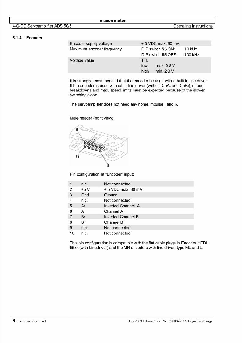
Male header (front view)
Pin configuration at “Encoder” input:
1 n.c. Not connected
2 +5 V + 5 VDC max. 80 mA
3 Gnd Ground
4 n.c. Not connected
5 A\ Inverted Channel A
6 A Channel A
7 B\ Inverted Channel B
8 B Channel B
9 n.c. Not connected
10 n.c. Not connected
This pin configuration is compatible with the flat cable plugs in Encoder HEDL55xx (with Linedriver) and the MR encoders with line driver, type ML and L.
8 maxon motor control July 2009 Edition / Doc. No. 538837-07 / Subject to change
7/27/2019 145391 ADS 50-5 Operating Instructions En
http://slidepdf.com/reader/full/145391-ads-50-5-operating-instructions-en 9/14
maxon motor
4-Q-DC Servoamplifier ADS 50/5 Operating Instructions
5.2 Outputs
5.2.1 Current monitor “Monitor I”
The servoamplifier makes a current actual value available for monitoring pur-poses. The signal is proportional to the motor current.
The “Monitor I” output is short-circuit protected.Output voltage range -10 ... +10 VDC
Output resistance 100 Ω
Gradient approx. 0.8 V/A
positive voltage on current monitoroutput
corresponds to a negative motorcurrent
negative voltage on current monitoroutput
corresponds to a positive motorcurrent
5.2.2 Speed monitor “Monitor n”
The speed monitor is primarily intended for the qualitative estimation of the dy-
namics. The absolute speed is determined by the properties of the speed sen-sors and by the setting of the nmax potentiometer. The output voltage of thespeed monitor is proportional to the number of revolutions. The output voltageof the speed monitor is 10 V when the maximum number of revolutions set bythe nmax potentiometer has been reached.The “Monitor n” output is short-circuit protected.
Output voltage range -10 ... +10 VDC
Output resistance 100 Ω
Example: -10 V corresponding speed -nmax (CCW)0 V corresponding speed 0 rpm
+10 V corresponding speed +nmax (CW)
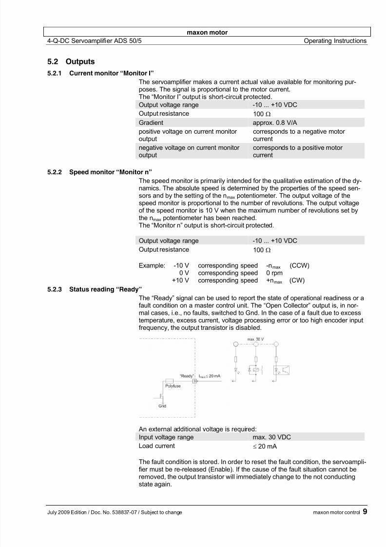
5.2.3 Status reading “Ready”
The “Ready” signal can be used to report the state of operational readiness or afault condition on a master control unit. The “Open Collector” output is, in nor-mal cases, i.e., no faults, switched to Gnd. In the case of a fault due to excesstemperature, excess current, voltage processing error or too high encoder inputfrequency, the output transistor is disabled.
An external additional voltage is required:
Input voltage range max. 30 VDC
Load current ≤ 20 mA
The fault condition is stored. In order to reset the fault condition, the servoampli-fier must be re-released (Enable). If the cause of the fault situation cannot be
removed, the output transistor will immediately change to the not conductingstate again.
July 2009 Edition / Doc. No. 538837-07 / Subject to change maxon motor control 9

7/27/2019 145391 ADS 50-5 Operating Instructions En
http://slidepdf.com/reader/full/145391-ads-50-5-operating-instructions-en 10/14
maxon motor
4-Q-DC Servoamplifier ADS 50/5 Operating Instructions
6 Additional Possible Adjustments
Potentiometer Function Position
left right
P6 ngain speed gain low high
P7 Igain current gain low high
P8 Icont continuous current limit lower higher
P8 Icont
P7 Igain
P6 ngain
6.1 Adjustments potentiometer P6 ngain
and potentiometer P7 Igain
In most applications, regulation setting is completely satisfactory using potentio-
meters P1 to P5. In special cases the transient response can be optimized by
setting the P6 “speed regulation gain” potentiometer. The P7 “current regulatorgain” potentiometer can, in addition, be adapted to the dynamics of the currentregulator.
It is recommend that the success of changes to the settings of P6 ngain and P7
Igain
be checked by measuring the transient response with an oscilloscope at the“Monitor n” and “Monitor I” outputs.
Pre-adjustment P6 ngain = 25 % and P7
Igain = 40 %.
10 maxon motor control July 2009 Edition / Doc. No. 538837-07 / Subject to change
7/27/2019 145391 ADS 50-5 Operating Instructions En
http://slidepdf.com/reader/full/145391-ads-50-5-operating-instructions-en 11/14
maxon motor
4-Q-DC Servoamplifier ADS 50/5 Operating Instructions
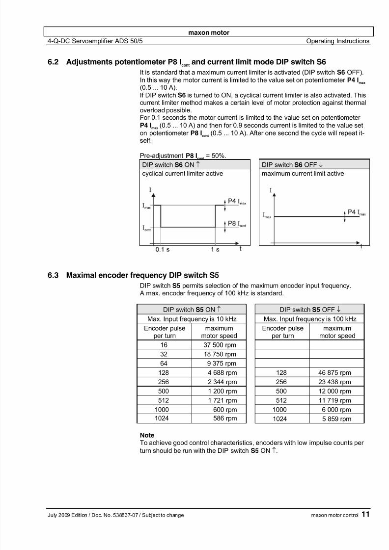
6.2 Adjustments potentiometer P8 Icont
and current limit mode DIP switch S6
It is standard that a maximum current limiter is activated (DIP switch S6 OFF).
In this way the motor current is limited to the value set on potentiometer P4 Imax
(0.5 ... 10 A).
If DIP switch S6 is turned to ON, a cyclical current limiter is also activated. Thiscurrent limiter method makes a certain level of motor protection against thermaloverload possible.For 0.1 seconds the motor current is limited to the value set on potentiometer
P4 Imax
(0.5 ... 10 A) and then for 0.9 seconds current is limited to the value set
on potentiometer P8 Icont
(0.5 ... 10 A). After one second the cycle will repeat it-self.
Pre-adjustment P8 Icont
= 50%.
DIP switch S6 ON ↑ DIP switch S6 OFF ↓
cyclical current limiter active maximum current limit active
11
6.3 Maximal encoder frequency DIP switch S5
DIP switch S5 permits selection of the maximum encoder input frequency. A max. encoder frequency of 100 kHz is standard.
DIP switch S5 ON ↑ DIP switch S5 OFF ↓
Max. Input frequency is 10 kHz Max. Input frequency is 100 kHz
Encoder pulseper turn
maximummotor speed
Encoder pulseper turn
maximummotor speed
16 37 500 rpm
32 18 750 rpm
64 9 375 rpm
128 4 688 rpm 128 46 875 rpm
256 2 344 rpm 256 23 438 rpm
500 1 200 rpm 500 12 000 rpm
512 1 721 rpm 512 11 719 rpm
1000 600 rpm 1000 6 000 rpm
1024 586 rpm 1024 5 859 rpm
NoteTo achieve good control characteristics, encoders with low impulse counts per
turn should be run with the DIP switch S5 ON ↑.
July 2009 Edition / Doc. No. 538837-07 / Subject to change maxon motor control
7/27/2019 145391 ADS 50-5 Operating Instructions En
http://slidepdf.com/reader/full/145391-ads-50-5-operating-instructions-en 12/14
maxon motor
4-Q-DC Servoamplifier ADS 50/5 Operating Instructions
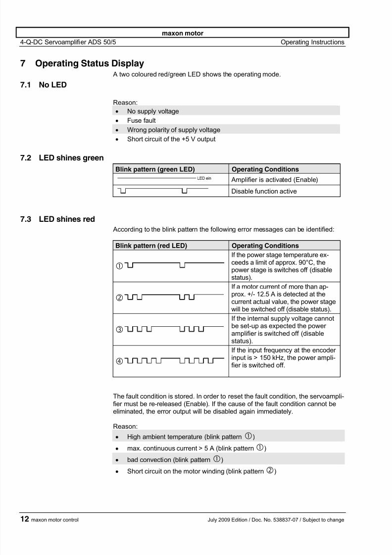
7 Operating Status Display A two coloured red/green LED shows the operating mode.
7.1 No LED
Reason:
• No supply voltage
• Fuse fault
• Wrong polarity of supply voltage
• Short circuit of the +5 V output
7.2 LED shines green
Blink pattern (green LED) Operating Conditions
Amplifier is activated (Enable)
Disable function active
7.3 LED shines red
According to the blink pattern the following error messages can be identified:
Blink pattern (red LED) Operating Conditions
If the power stage temperature ex-ceeds a limit of approx. 90°C, thepower stage is switches off (disablestatus).
If a motor current of more than ap-prox. +/- 12.5 A is detected at thecurrent actual value, the power stagewill be switched off (disable status).
If the internal supply voltage cannotbe set-up as expected the poweramplifier is switched off (disablestatus).
If the input frequency at the encoderinput is > 150 kHz, the power ampli-fier is switched off.
The fault condition is stored. In order to reset the fault condition, the servoampli-fier must be re-released (Enable). If the cause of the fault condition cannot beeliminated, the error output will be disabled again immediately.
Reason:
• High ambient temperature (blink pattern)
• max. continuous current > 5 A (blink pattern)
• bad convection (blink pattern)
• Short circuit on the motor winding (blink pattern)
12 maxon motor control July 2009 Edition / Doc. No. 538837-07 / Subject to change
7/27/2019 145391 ADS 50-5 Operating Instructions En
http://slidepdf.com/reader/full/145391-ads-50-5-operating-instructions-en 13/14
maxon motor
4-Q-DC Servoamplifier ADS 50/5 Operating Instructions
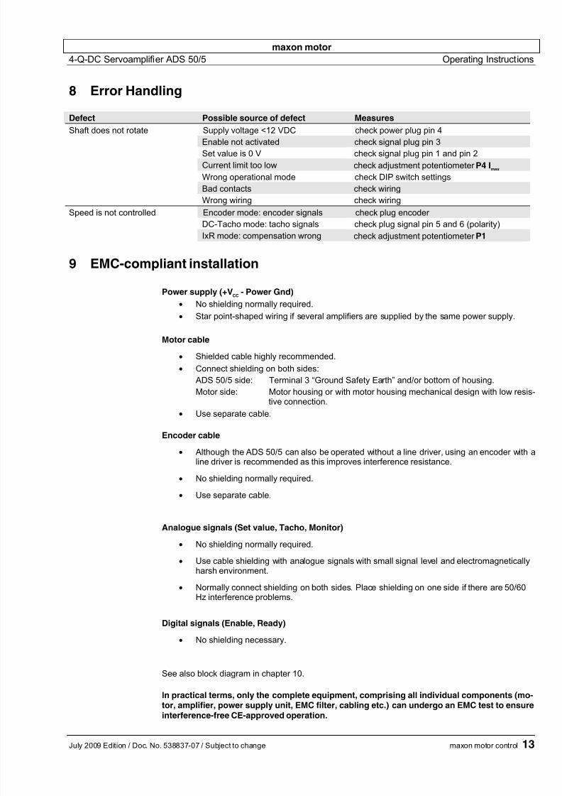
8 Error Handling
Defect Possible source of defect Measures
Shaft does not rotate Supply voltage <12 VDC check power plug pin 4
Enable not activated check signal plug pin 3
Set value is 0 V check signal plug pin 1 and pin 2
Current limit too low check adjustment potentiometer P4 Imax
Wrong operational mode check DIP switch settings
Bad contacts check wiring
Wrong wiring check wiring
Speed is not controlled Encoder mode: encoder signals check plug encoder
DC-Tacho mode: tacho signals check plug signal pin 5 and 6 (polarity)
IxR mode: compensation wrong check adjustment potentiometer P1
9 EMC-compliant installation
Power supply (+VCC
- Power Gnd)
• No shielding normally required.
• Star point-shaped wiring if several amplifiers are supplied by the same power supply.
Motor cable
• Shielded cable highly recommended.
• Connect shielding on both sides:
ADS 50/5 side: Terminal 3 “Ground Safety Earth” and/or bottom of housing.
Motor side: Motor housing or with motor housing mechanical design with low resis-tive connection.
• Use separate cable.
Encoder cable
• Although the ADS 50/5 can also be operated without a line driver, using an encoder with aline driver is recommended as this improves interference resistance.
• No shielding normally required.
• Use separate cable.
Analogue signals (Set value, Tacho, Monitor)
• No shielding normally required.
• Use cable shielding with analogue signals with small signal level and electromagneticallyharsh environment.
• Normally connect shielding on both sides. Place shielding on one side if there are 50/60Hz interference problems.
Digital signals (Enable, Ready)
• No shielding necessary.
See also block diagram in chapter 10.
In practical terms, only the complete equipment, comprising all individual components (mo-tor, amplifier, power supply unit, EMC filter, cabling etc.) can undergo an EMC test to ensureinterference-free CE-approved operation.
July 2009 Edition / Doc. No. 538837-07 / Subject to change maxon motor control 13
7/27/2019 145391 ADS 50-5 Operating Instructions En
http://slidepdf.com/reader/full/145391-ads-50-5-operating-instructions-en 14/14
maxon motor
4-Q-DC Servoamplifier ADS 50/5 Operating Instructions
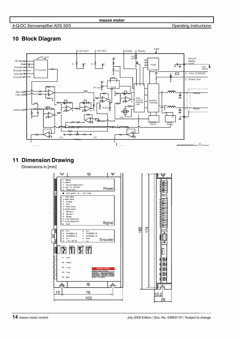
10 Block Diagram
ReadyEnable-12V OUT
-12V
+12V
+5V
Supply
DIP6
-12V
+12V
PTC
Currentlimit
P8 I cont
PWM,Control &ProtectionLogic
MOSFETFull-Bridge
CurrentDetector
VoltageDetector
P1 IxR
P4 Imax
Monitor I
-Motor
+Motor
Power Gnd
+Vcc 12-50VDC
+12V OUT
1K +12V 1K
DIP1
P6 n gainP5 gain
DIP2
DIP3
P2 Offset-12V+12V
Monitor n
P3 n max
DIP4
-Tacho Inpu t
-Set value
+Set value
Encoder B\
Encoder B
Encoder A\
Encoder A
Gnd
+5V/80mA
DIP5
F/V Converter
+5V
P7 I gain
Poly-
fuse
LED
3
GroundSafetyEarth
earthoptional
3
Case
11
2
4
5
11 Dimension DrawingDimensions in [mm]
14 maxon motor control July 2009 Edition / Doc. No. 538837-07 / Subject to change