Embed Size (px)
Citation preview
Technical DataOriginal Instructions
1443 Series Accelerometers SpecificationsCatalog Numbers 1443-ACC-GP series, 1443-ACC-VO series, 1443-ACC-IS series, 1443-ACC-AT series, 1443-ACC-LF-T, 1443-ACC-HF-T
Summary of Changes
Topic Page
Sensor Selection Process 4
Shield Wire Isolation Sensor and Cable Selection 8
Sensor Quick Reference 11
Metric and Imperial Mounting 13
Sensors 14
Sensor Certifications and Approvals 42
Accessories 44
Sensor Cross-reference - 1443 Series (New) to 9000 Series (Old) 56
Additional Resources 59
Topic Page
Added new topic ‘API-670 compliance’ 10
Added Important for sensors manufactured earlier than October 2017 10
Added Hall-effect Speed Sensor information to quick reference section 13, 42
Sensitivity changed from (±10%) to (±5%) global change 14
Updated footnote for sensitivity tolerance 14
Updated all Sensor tables frequency ranges with new ranges 14
Exception for sensor compliance for six Accelerometers 16

1443 Series Accelerometers Specifications
Rockwell Automation® 1443 Series Accelerometers are general-purpose sensors that are used to measure vibration on industrial machinery. The 1443 Series family also includes sensors with these varied capabilities:
• Low frequency, as low as 0.1 Hz or 6 cpm• High frequency, up to 20 kHz or 1200 kcpm• Velocity output, internal integrator• Hazardous area approved• Dual accelerometer and temperature output
Typical Vibration Measurement Systems
Accelerometers are either permanently mounted or carried from point-to-point in a route-based measurement or analysis scheme. The entire measurement system, however, can take on various forms, depending on sensor type and the goal of the monitoring program. The following examples illustrate vibration measurement and monitor systems.
Figure 1 - Dynamix™ System and Permanently Installed Accelerometers
Figure 2 - Portable Data Collector and Permanently Installed Accelerometers
Permanently Installed Accelerometers Sensor Cables to Dynamix™ 1444
Permanently Installed Accelerometers
Sensor Cables
Switch Box
Sensor to Data Collector Cable
Dynamix™ 2500
2 Rockwell Automation Publication 1443-TD001D-EN-P - March 2019
1443 Series Accelerometers Specifications
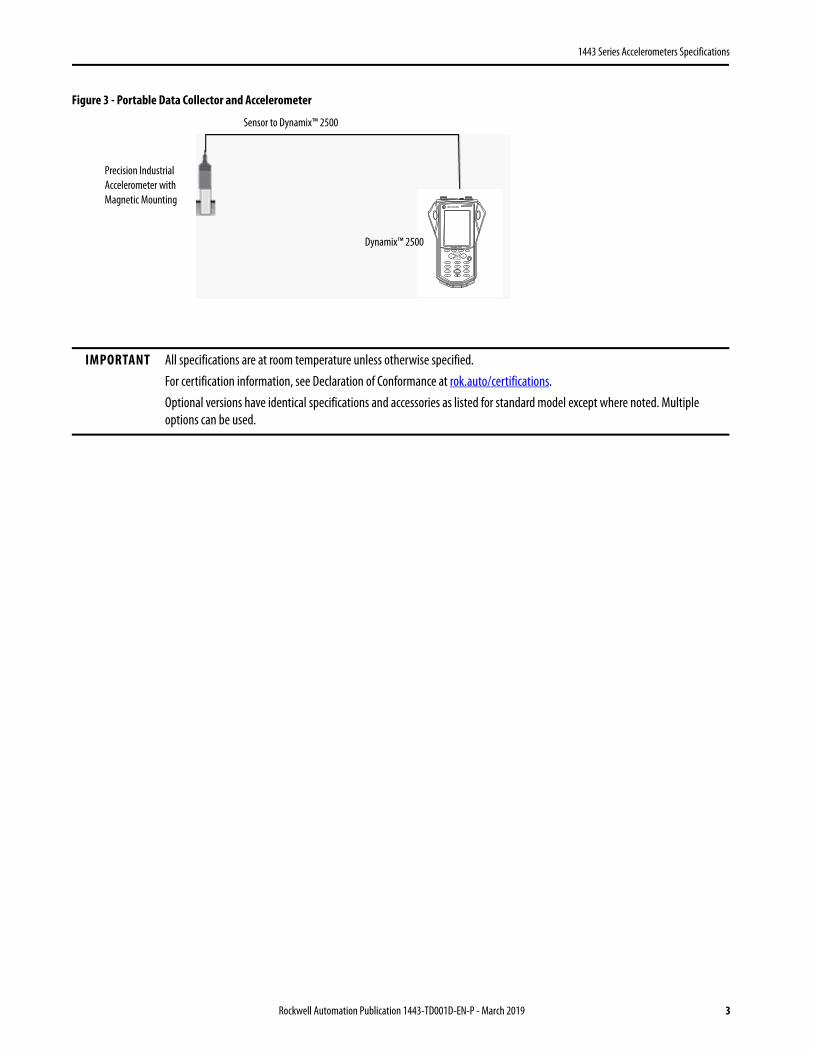
Figure 3 - Portable Data Collector and Accelerometer
IMPORTANT All specifications are at room temperature unless otherwise specified.For certification information, see Declaration of Conformance at rok.auto/certifications.Optional versions have identical specifications and accessories as listed for standard model except where noted. Multiple options can be used.
Sensor to Dynamix™ 2500
Precision Industrial Accelerometer with Magnetic Mounting
Dynamix™ 2500
Rockwell Automation Publication 1443-TD001D-EN-P - March 2019 3

1443 Series Accelerometers Specifications
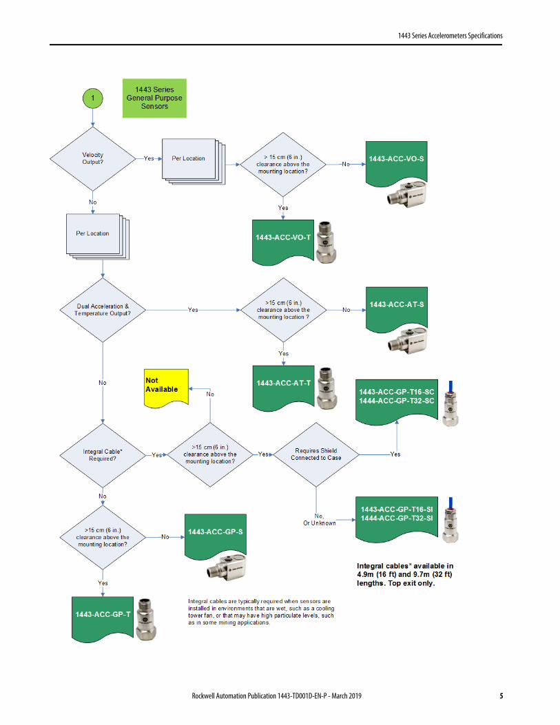
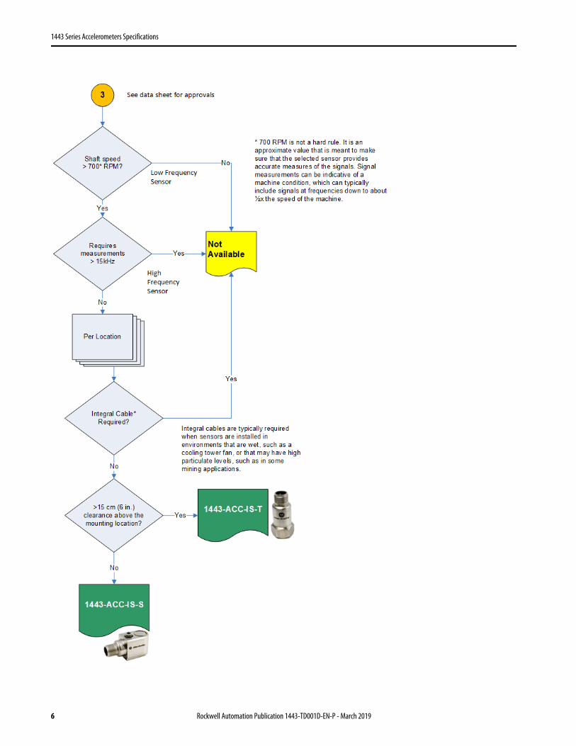
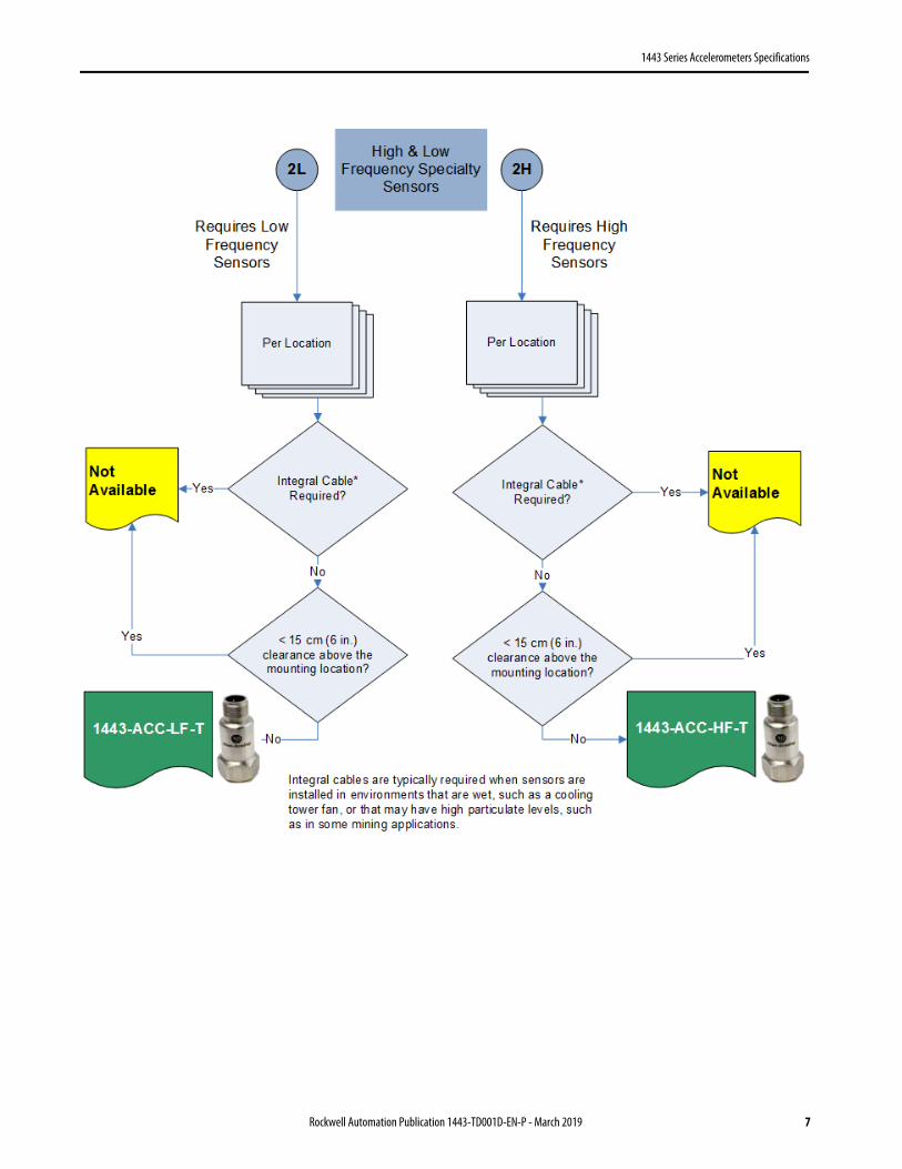
Sensor Selection Process
This flowchart illustrates the process that you can follow to select the appropriate sensor for your application.
Figure 4 - Sensor Selection Flowchart
4 Rockwell Automation Publication 1443-TD001D-EN-P - March 2019
1443 Series Accelerometers Specifications
Rockwell Automation Publication 1443-TD001D-EN-P - March 2019 5
1443 Series Accelerometers Specifications
6 Rockwell Automation Publication 1443-TD001D-EN-P - March 2019
1443 Series Accelerometers Specifications
Rockwell Automation Publication 1443-TD001D-EN-P - March 2019 7
1443 Series Accelerometers Specifications
Shield Wire Isolation Sensor and Cable Selection
The 1443 Series include sensor and cable solutions that isolate the shield wire from the sensor or ground the shield wire to the sensor. For standard sensors, select either shield isolated or shield grounded cables. When a sensor with an integral cable is required, select a sensor with the shield wire isolated from the sensor or that has its shield wire grounded to the sensor.
When a shield to sensor isolated solution is required, which is the normal recommended method:• If a sensor without an integral cable is required, use an accessory cable that has its shield wire isolated from the
sensor connector. Select a cable with ‘IBC’ in its catalog number, for example, 1443-CBL-MS2IBC-32S.• If a sensor with an integral cable is required, use a sensor with its shield wire isolated from the sensor. Select a
sensor with ‘SI’ in its catalog number, for example, 1443-ACC-GP-T16-SI.
When a shield grounded sensor is required:• If a sensor without an integral cable is required, use an accessory cable that has its shield wire that is grounded to
the sensor connector. Select a cable with ‘GBC’ in its catalog number, for example, 1443-CBL-MS2GBC-16S. • If a sensor with an integral cable is required, use a sensor with its shield wire that is grounded to sensor case. Select
a sensor with ‘SC’ in its catalog number, for example, 1443-ACC-GP-T16-SC.
The recommended solution is to connect the shield at the measurement system and leave it isolated at the sensor end. Use IBC version cables or ‘SI’ version sensors when an integral cable sensor is required. However, when EMI problems are present or expected, then a shield case grounded solution can prove to be a better design.
When signal noise or interference is a problem or concern, you must understand the source of the problem to resolve it. Noise can be introduced into signals from accelerometers through these common phenomena:
• Electromagnetic Interference (EMI)
EMI is the introduction of unwanted signals into an electronic device from electromagnetic fields that another electronic device generated. Televisions, radars, vehicles, variable-frequency drives (VFDs), and other electronic devices can produce high powered electromagnetic fields. EMI can be introduced into the measurement system via the signal wiring when that wiring acts as an antenna, which occurs when one end of the wire is ungrounded.
When EMI occurs, it typically results in signals being introduced at discrete frequencies that are related to the signal source. The impact on measurements is dependent on the magnitude and specific frequency of the signal that is induced. This occurrence is relative to the measurement systems design signal magnitude and frequency range and the expected signals that are intended to be measured.
• Ground Loops
In electronics, a ground loop is caused when a device has multiple paths for electricity to flow to ground. In a measurement system, this scenario commonly occurs when a signal wire is grounded at both ends, with each end having another potential (resistance) to ground.
The key for accelerometer measurement systems is knowing if the machine case, or bearing housing, to which the sensor is attached, is grounded or not. While a new machine installation can be isolated, changes are possible over the life of the machine as wear occurs, maintenance is performed, and other changes are made.
Regardless the source, when present these signals or noise can result in significant error in measurements. The result can be random and inexplicable machine alarms and trips, erroneous condition assessment / diagnosis, and possible damage to the instrumentation. If the source of the noise is clear, and there is only one concern, then the corrective action is clear, depending on the source of the problem, try the following:
8 Rockwell Automation Publication 1443-TD001D-EN-P - March 2019
1443 Series Accelerometers Specifications
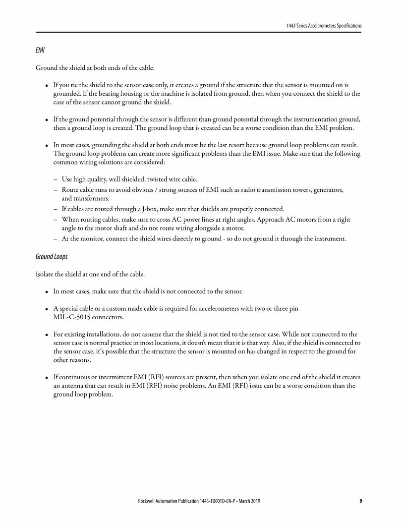
EMI
Ground the shield at both ends of the cable.
• If you tie the shield to the sensor case only, it creates a ground if the structure that the sensor is mounted on is grounded. If the bearing housing or the machine is isolated from ground, then when you connect the shield to the case of the sensor cannot ground the shield.
• If the ground potential through the sensor is different than ground potential through the instrumentation ground, then a ground loop is created. The ground loop that is created can be a worse condition than the EMI problem.
• In most cases, grounding the shield at both ends must be the last resort because ground loop problems can result. The ground loop problems can create more significant problems than the EMI issue. Make sure that the following common wiring solutions are considered:
– Use high quality, well shielded, twisted wire cable.– Route cable runs to avoid obvious / strong sources of EMI such as radio transmission towers, generators,
and transformers.– If cables are routed through a J-box, make sure that shields are properly connected.– When routing cables, make sure to cross AC power lines at right angles. Approach AC motors from a right
angle to the motor shaft and do not route wiring alongside a motor.– At the monitor, connect the shield wires directly to ground - so do not ground it through the instrument.
Ground Loops
Isolate the shield at one end of the cable.
• In most cases, make sure that the shield is not connected to the sensor.
• A special cable or a custom made cable is required for accelerometers with two or three pin MIL-C-5015 connectors.
• For existing installations, do not assume that the shield is not tied to the sensor case. While not connected to the sensor case is normal practice in most locations, it doesn't mean that it is that way. Also, if the shield is connected to the sensor case, it’s possible that the structure the sensor is mounted on has changed in respect to the ground for other reasons.
• If continuous or intermittent EMI (RFI) sources are present, then when you isolate one end of the shield it creates an antenna that can result in EMI (RFI) noise problems. An EMI (RFI) issue can be a worse condition than the ground loop problem.
Rockwell Automation Publication 1443-TD001D-EN-P - March 2019 9

1443 Series Accelerometers Specifications
API-670 Compliance
All 1443 Series sensors are compliant to the American Petroleum Institute (API) Standard 670, 5th Edition, November 2014, with the following exceptions:
• Side exit sensors have an outside diameter greater than 25 mm (1 in.) as specified by API-670 paragraph 5.2.1.5.• Calibration frequency is 80 Hz, in accordance with ISO standard 9001-2008, rather than 100 Hz as specified in
API-670 Table 1 note f.• Only the standard 16 ft cables are nominally 5 m (200 in.) as specified by API-670 paragraph 5.2.2.2.• Cables do not ship with loose heat-shrink tubing for labeling, as specified by API-670 paragraph 5.2.2.3.
Perhaps the most important attribute of the sensor, per the standard, is its accuracy. The standard specifies accuracy requirements for accelerometers in the following table.
The 1443 Series sensor is ± 5% across the entire operating range of the sensor. This sensor range significantly exceeds the requirement of only testing within the temperature range. Among sensors advertised as API compliant, this provides a much more consistent and accurate measurement than most sensors compared to the requirement of just ±20%.
Table 1 - Machinery Protection System Accuracy Requirements
Accelerometers and Accelerometer Extension Cables(1)
(1) During the testing of the accelerometers, the parameter under test is the only parameter that is varied. All other parameters remain constant.
Temperature Accuracy Requirements as a Function of Temperature
Test Range Operating / Storage Range Within Testing Range Outside Testing Range but Within Operating Range
20...30 °C (68...86 °F)
–55...+120 °C (–65...+250 °F)
Principal axis sensitivity(4): 100 mV/g ± 5% Amplitude linearity: 1% from 0.1...50 g peak(2)
Frequency response(3): ±3 dB from 10 Hz to 10 kHz, referenced to the actual measured principal axis sensitivity(4)
(2) Conditions of test at any one temperature within the testing range, at any single frequency that is not specified but is within the specified frequency range of the transducer.
(3) Frequency response testing conditions, at any one temperature within the testing range, at an excitation amplitude that is not specified but is within the specified amplitude range of the transducer.
(4) Principal axis sensitivity testing conditions (test range), at any one temperature within the testing range set at 100 Hz, at an excitation amplitude that is not specified but is within the specified amplitude range of the transducer. Operating range at any one temperature within the operating range, at 100 Hz, at an excitation amplitude that is not specified but is within the specified amplitude range of the transducer.
Principal axis sensitivity(4): 100 mV/g ± 20%
IMPORTANT Sensors manufactured earlier than October 2017 can have sensitivity variances of up to ± 10% across the operating range.
10 Rockwell Automation Publication 1443-TD001D-EN-P - March 2019
1443 Series Accelerometers Specifications
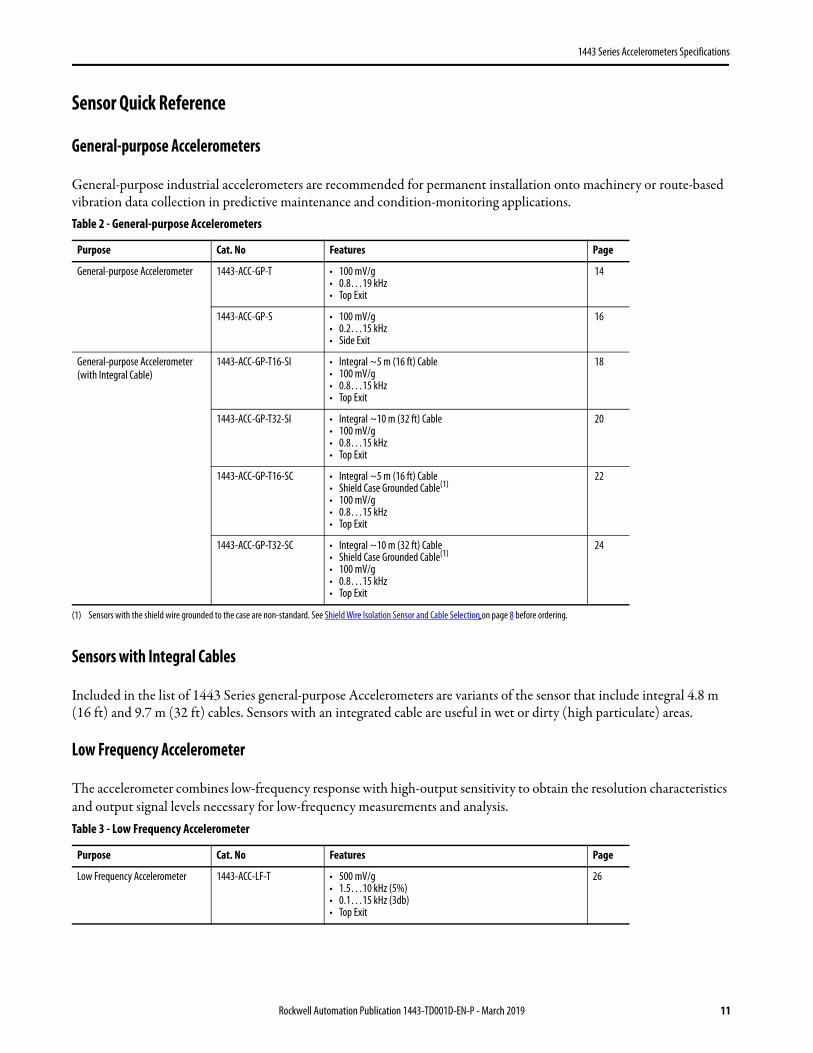
Sensor Quick Reference
General-purpose Accelerometers
General-purpose industrial accelerometers are recommended for permanent installation onto machinery or route-based vibration data collection in predictive maintenance and condition-monitoring applications.
Sensors with Integral Cables
Included in the list of 1443 Series general-purpose Accelerometers are variants of the sensor that include integral 4.8 m (16 ft) and 9.7 m (32 ft) cables. Sensors with an integrated cable are useful in wet or dirty (high particulate) areas.
Low Frequency Accelerometer
The accelerometer combines low-frequency response with high-output sensitivity to obtain the resolution characteristics and output signal levels necessary for low-frequency measurements and analysis.
Table 2 - General-purpose Accelerometers
Purpose Cat. No Features Page
General-purpose Accelerometer 1443-ACC-GP-T • 100 mV/g • 0.8…19 kHz• Top Exit
14
1443-ACC-GP-S • 100 mV/g • 0.2…15 kHz• Side Exit
16
General-purpose Accelerometer (with Integral Cable)
1443-ACC-GP-T16-SI • Integral ~5 m (16 ft) Cable• 100 mV/g • 0.8…15 kHz• Top Exit
18
1443-ACC-GP-T32-SI • Integral ~10 m (32 ft) Cable • 100 mV/g • 0.8…15 kHz• Top Exit
20
1443-ACC-GP-T16-SC • Integral ~5 m (16 ft) Cable• Shield Case Grounded Cable(1)
• 100 mV/g • 0.8…15 kHz• Top Exit
(1) Sensors with the shield wire grounded to the case are non-standard. See Shield Wire Isolation Sensor and Cable Selection on page 8 before ordering.
22
1443-ACC-GP-T32-SC • Integral ~10 m (32 ft) Cable• Shield Case Grounded Cable(1)
• 100 mV/g • 0.8…15 kHz• Top Exit
24
Table 3 - Low Frequency Accelerometer
Purpose Cat. No Features Page
Low Frequency Accelerometer 1443-ACC-LF-T • 500 mV/g• 1.5…10 kHz (5%)• 0.1…15 kHz (3db)• Top Exit
26
Rockwell Automation Publication 1443-TD001D-EN-P - March 2019 11

1443 Series Accelerometers Specifications
High Frequency Accelerometer
When you test, monitor vibrations, and analyze the frequency of machinery where frequencies greater than approximately 15 kHz, the frequencies must be measured.
Specialty Accelerometers
These sensors are available for applications that require velocity output and temperature output from the sensor.• Velocity Output• Acceleration and Temperature
Table 4 - High Frequency Accelerometer
Purpose Cat. No Features Page
High Frequency Accelerometer 1443-ACC-HF-T • 50 mV/g• 0.8…20 kHz• Top exit
28
Table 5 - Specialty Accelerometers
Purpose Cat. No Features Page
Velocity Output Accelerometer 1443-ACC-VO-T Output is integrated to velocity100 mV/ips2…6 kHzOutput ±50 in/sTop Exit
30
Velocity Output Accelerometer 1443-ACC-VO-S Output is integrated to velocity100 mV/ips2…6 kHzOutput ±50 in/sSide Exit
32
Combination Acceleration and Temperature 1443-ACC-AT-T 100 mV/g0.8…15 kHz10 mV/°CTop Exit
34
Combination Acceleration and Temperature 1443-ACC-AT-S 100 mV/g0.8…15 kHz10 mV/°CSide Exit
36
12 Rockwell Automation Publication 1443-TD001D-EN-P - March 2019
1443 Series Accelerometers Specifications
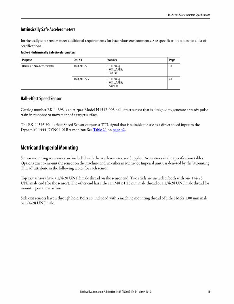
Intrinsically Safe Accelerometers
Intrinsically safe sensors meet additional requirements for hazardous environments. See specification tables for a list of certifications.
Hall-effect Speed Sensor
Catalog number EK-44395 is an Airpax Model H1512-005 hall-effect sensor that is designed to generate a steady pulse train in response to movement of a target surface.
The EK-44395 Hall-effect Speed Sensor outputs a TTL signal that is suitable for use as a direct speed input to the Dynamix™ 1444-DYN04-01RA monitor. See Table 21 on page 42.
Metric and Imperial Mounting
Sensor mounting accessories are included with the accelerometer, see Supplied Accessories in the specification tables. Options exist to mount the sensor on the machine end, in either in Metric or Imperial units, as denoted by the ‘Mounting Thread’ attribute in the following tables for each sensor.
Top exit sensors have a 1/4-28 UNF female thread on the sensor end. Two studs are included, both with one 1/4-28 UNF male end (for the sensor). The other end has either an M8 x 1.25 mm male thread or a 1/4-28 UNF male thread for mounting on the machine.
Side exit sensors have a through hole. Bolts are included with a machine mounting thread of either M6 x 1.00 mm male or 1/4-28 UNF male.
Table 6 - Intrinsically Safe Accelerometers
Purpose Cat. No Features Page
Hazardous Area Accelerometer 1443-ACC-IS-T • 100 mV/g• 0.8…15 kHz• Top Exit
38
1443-ACC-IS-S • 100 mV/g• 0.8…15 kHz• Side Exit
40
Rockwell Automation Publication 1443-TD001D-EN-P - March 2019 13
1443 Series Accelerometers Specifications
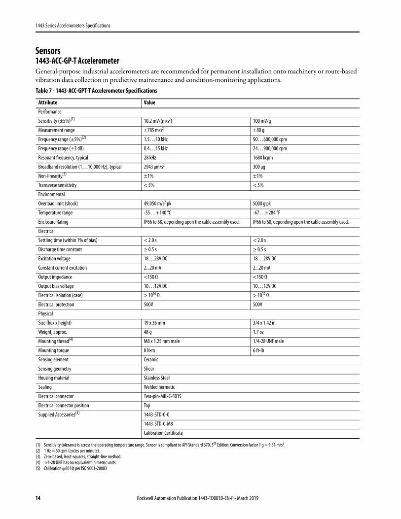
Sensors1443-ACC-GP-T AccelerometerGeneral-purpose industrial accelerometers are recommended for permanent installation onto machinery or route-based vibration data collection in predictive maintenance and condition-monitoring applications.Table 7 - 1443-ACC-GPT-T Accelerometer Specifications
Attribute Value
Performance
Sensitivity (±5%)(1)
(1) Sensitivity tolerance is across the operating temperature range. Sensor is compliant to API Standard 670, 5th Edition. Conversion factor 1 g = 9.81 m/s2.
10.2 mV/(m/s2) 100 mV/g
Measurement range ±785 m/s2 ±80 g
Frequency range (±5%)(2)
(2) 1 Hz = 60 cpm (cycles per minute).
1.5…10 kHz 90…600,000 cpm
Frequency range (±3 dB) 0.4…15 kHz 24…900,000 cpm
Resonant frequency, typical 28 kHz 1680 kcpm
Broadband resolution (1…10,000 Hz), typical 2943 μm/s2 300 μg
Non-linearity(3)
(3) Zero-based, least-squares, straight-line method.
±1% ±1%
Transverse sensitivity < 5% < 5%
Environmental
Overload limit (shock) 49,050 m/s2 pk 5000 g pk
Temperature range -55…+140 °C -67…+284 °F
Enclosure Rating IP66 to 68, depending upon the cable assembly used. IP66 to 68, depending upon the cable assembly used.
Electrical
Settling time (within 1% of bias) < 2.0 s < 2.0 s
Discharge time constant ≥ 0.5 s ≥ 0.5 s
Excitation voltage 18…28V DC 18…28V DC
Constant current excitation 2...20 mA 2...20 mA
Output impedance <150 Ω <150 Ω
Output bias voltage 10…12V DC 10…12V DC
Electrical isolation (case) > 1010 Ω > 1010 Ω
Electrical protection 500V 500V
Physical
Size (hex x height) 19 x 36 mm 3/4 x 1.42 in.
Weight, approx. 48 g 1.7 oz
Mounting thread(4)
(4) 1/4-28 UNF has no equivalent in metric units.
M8 x 1.25 mm male 1/4-28 UNF male
Mounting torque 8 N•m 6 ft•lb
Sensing element Ceramic
Sensing geometry Shear
Housing material Stainless Steel
Sealing Welded hermetic
Electrical connector Two-pin-MIL-C-5015
Electrical connector position Top
Supplied Accessories(5)
(5) Calibration @80 Hz per ISO 9001-20083
1443-STD-0-0
1443-STD-0-M8
Calibration Certificate
14 Rockwell Automation Publication 1443-TD001D-EN-P - March 2019
1443 Series Accelerometers Specifications
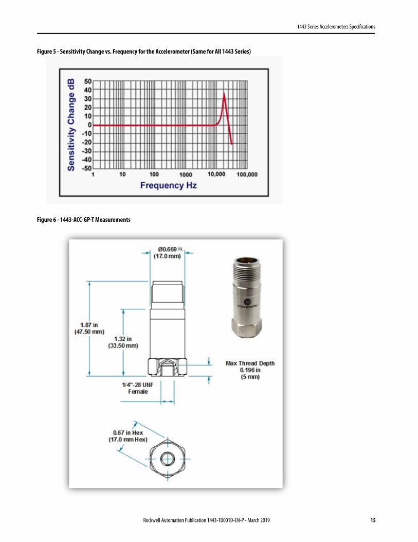
Figure 5 - Sensitivity Change vs. Frequency for the Accelerometer (Same for All 1443 Series)
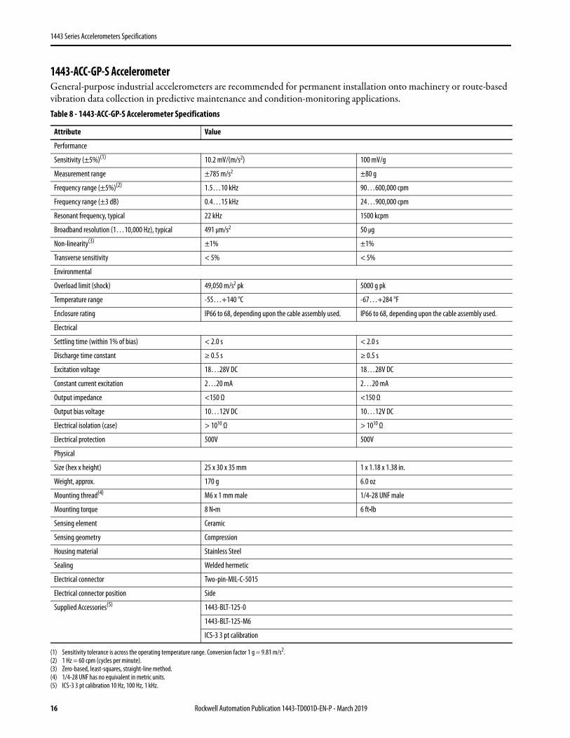
Figure 6 - 1443-ACC-GP-T Measurements
in.
Rockwell Automation Publication 1443-TD001D-EN-P - March 2019 15
1443 Series Accelerometers Specifications
1443-ACC-GP-S AccelerometerGeneral-purpose industrial accelerometers are recommended for permanent installation onto machinery or route-based vibration data collection in predictive maintenance and condition-monitoring applications. Table 8 - 1443-ACC-GP-S Accelerometer Specifications
Attribute Value
Performance
Sensitivity (±5%)(1)
(1) Sensitivity tolerance is across the operating temperature range. Conversion factor 1 g = 9.81 m/s2.
10.2 mV/(m/s2) 100 mV/g
Measurement range ±785 m/s2 ±80 g
Frequency range (±5%)(2)
(2) 1 Hz = 60 cpm (cycles per minute).
1.5…10 kHz 90…600,000 cpm
Frequency range (±3 dB) 0.4…15 kHz 24…900,000 cpm
Resonant frequency, typical 22 kHz 1500 kcpm
Broadband resolution (1…10,000 Hz), typical 491 μm/s2 50 μg
Non-linearity(3)
(3) Zero-based, least-squares, straight-line method.
±1% ±1%
Transverse sensitivity < 5% < 5%
Environmental
Overload limit (shock) 49,050 m/s2 pk 5000 g pk
Temperature range -55…+140 °C -67…+284 °F
Enclosure rating IP66 to 68, depending upon the cable assembly used. IP66 to 68, depending upon the cable assembly used.
Electrical
Settling time (within 1% of bias) < 2.0 s < 2.0 s
Discharge time constant ≥ 0.5 s ≥ 0.5 s
Excitation voltage 18…28V DC 18…28V DC
Constant current excitation 2…20 mA 2…20 mA
Output impedance <150 Ω <150 Ω
Output bias voltage 10…12V DC 10…12V DC
Electrical isolation (case) > 1010 Ω > 1010 Ω
Electrical protection 500V 500V
Physical
Size (hex x height) 25 x 30 x 35 mm 1 x 1.18 x 1.38 in.
Weight, approx. 170 g 6.0 oz
Mounting thread(4)
(4) 1/4-28 UNF has no equivalent in metric units.
M6 x 1 mm male 1/4-28 UNF male
Mounting torque 8 N•m 6 ft•lb
Sensing element Ceramic
Sensing geometry Compression
Housing material Stainless Steel
Sealing Welded hermetic
Electrical connector Two-pin-MIL-C-5015
Electrical connector position Side
Supplied Accessories(5)
(5) ICS-3 3 pt calibration 10 Hz, 100 Hz, 1 kHz.
1443-BLT-125-0
1443-BLT-125-M6
ICS-3 3 pt calibration
16 Rockwell Automation Publication 1443-TD001D-EN-P - March 2019
1443 Series Accelerometers Specifications
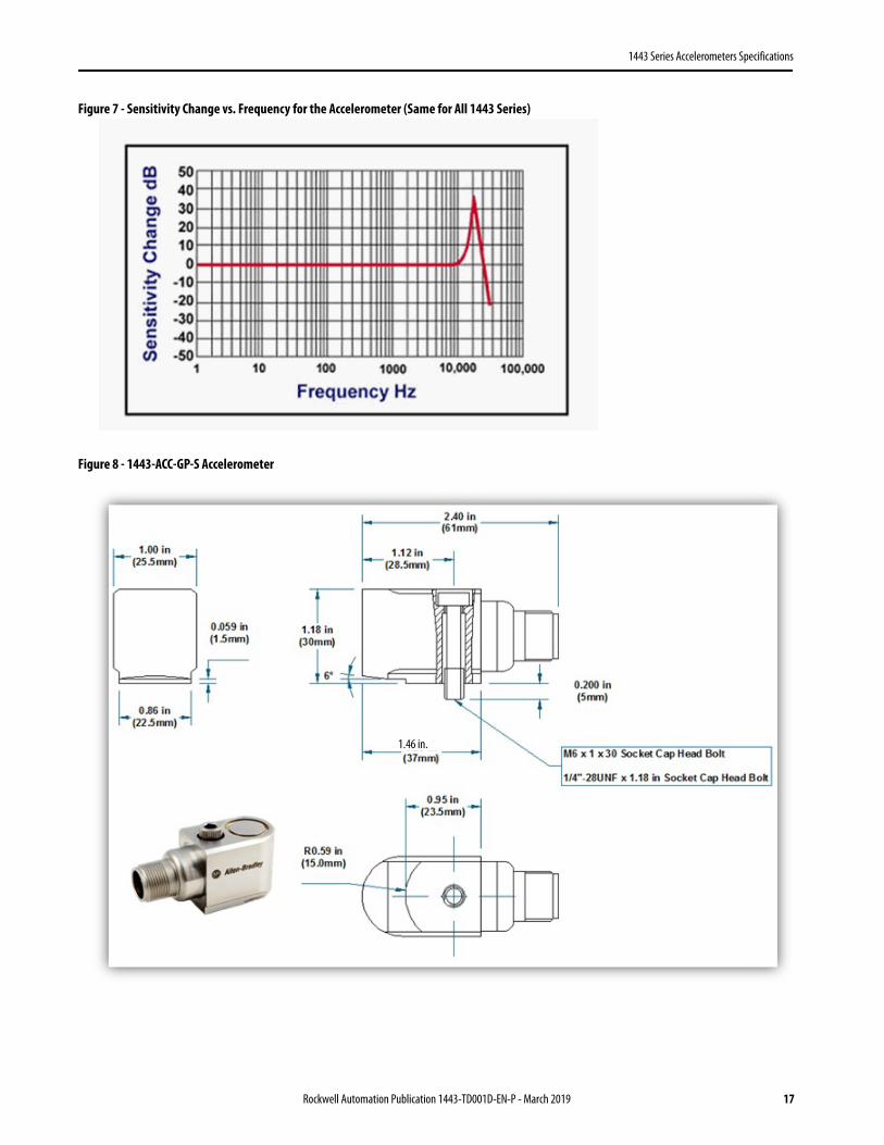
Figure 7 - Sensitivity Change vs. Frequency for the Accelerometer (Same for All 1443 Series)
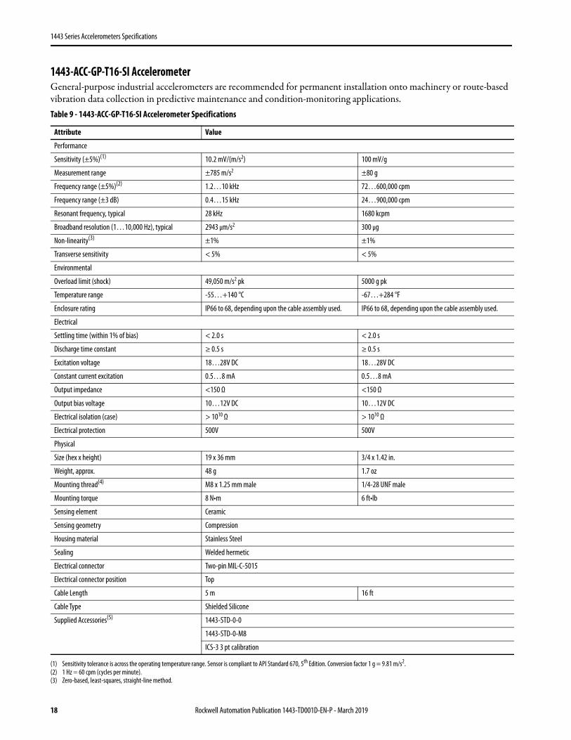
Figure 8 - 1443-ACC-GP-S Accelerometer
1.46 in.
Rockwell Automation Publication 1443-TD001D-EN-P - March 2019 17
1443 Series Accelerometers Specifications
1443-ACC-GP-T16-SI AccelerometerGeneral-purpose industrial accelerometers are recommended for permanent installation onto machinery or route-based vibration data collection in predictive maintenance and condition-monitoring applications.Table 9 - 1443-ACC-GP-T16-SI Accelerometer Specifications
Attribute Value
Performance
Sensitivity (±5%)(1)
(1) Sensitivity tolerance is across the operating temperature range. Sensor is compliant to API Standard 670, 5th Edition. Conversion factor 1 g = 9.81 m/s2.
10.2 mV/(m/s2) 100 mV/g
Measurement range ±785 m/s2 ±80 g
Frequency range (±5%)(2)
(2) 1 Hz = 60 cpm (cycles per minute).
1.2…10 kHz 72…600,000 cpm
Frequency range (±3 dB) 0.4…15 kHz 24…900,000 cpm
Resonant frequency, typical 28 kHz 1680 kcpm
Broadband resolution (1…10,000 Hz), typical 2943 μm/s2 300 μg
Non-linearity(3)
(3) Zero-based, least-squares, straight-line method.
±1% ±1%
Transverse sensitivity < 5% < 5%
Environmental
Overload limit (shock) 49,050 m/s2 pk 5000 g pk
Temperature range -55…+140 °C -67…+284 °F
Enclosure rating IP66 to 68, depending upon the cable assembly used. IP66 to 68, depending upon the cable assembly used.
Electrical
Settling time (within 1% of bias) < 2.0 s < 2.0 s
Discharge time constant ≥ 0.5 s ≥ 0.5 s
Excitation voltage 18…28V DC 18…28V DC
Constant current excitation 0.5…8 mA 0.5…8 mA
Output impedance <150 Ω <150 Ω
Output bias voltage 10…12V DC 10…12V DC
Electrical isolation (case) > 1010 Ω > 1010 Ω
Electrical protection 500V 500V
Physical
Size (hex x height) 19 x 36 mm 3/4 x 1.42 in.
Weight, approx. 48 g 1.7 oz
Mounting thread(4) M8 x 1.25 mm male 1/4-28 UNF male
Mounting torque 8 N•m 6 ft•lb
Sensing element Ceramic
Sensing geometry Compression
Housing material Stainless Steel
Sealing Welded hermetic
Electrical connector Two-pin MIL-C-5015
Electrical connector position Top
Cable Length 5 m 16 ft
Cable Type Shielded Silicone
Supplied Accessories(5) 1443-STD-0-0
1443-STD-0-M8
ICS-3 3 pt calibration
18 Rockwell Automation Publication 1443-TD001D-EN-P - March 2019

1443 Series Accelerometers Specifications
Figure 9 - Sensitivity Change vs. Frequency for the Accelerometer (Same for All 1443 Series)
Figure 10 - 1443-ACC-GP-T16-SI Accelerometer
(4) 1/4-28 UNF has no equivalent in metric units.(5) ICS-3 3 pt calibration 10 Hz, 100 Hz, 1 kHz.
16 ft5 m
Rockwell Automation Publication 1443-TD001D-EN-P - March 2019 19
1443 Series Accelerometers Specifications
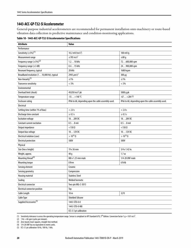
1443-ACC-GP-T32-SI AccelerometerGeneral-purpose industrial accelerometers are recommended for permanent installation onto machinery or route-based vibration data collection in predictive maintenance and condition-monitoring applications.Table 10 - 1443-ACC-GP-T32-SI Accelerometer Specifications
Attribute Value
Performance
Sensitivity (±5%)(1)
(1) Sensitivity tolerance is across the operating temperature range. Sensor is compliant to API Standard 670, 5th Edition. Conversion factor 1 g = 9.81 m/s2.
10.2 mV/(m/s2) 100 mV/g
Measurement range ±785 m/s2 ±80 g
Frequency range (±5%)(2)
(2) 1 Hz = 60 cpm (cycles per minute).
1.2…10 kHz 72…600,000 cpm
Frequency range (±3 dB) 0.4…15 kHz 24…900,000 cpm
Resonant frequency, typical 28 kHz 1680 kcpm
Broadband resolution (1…10,000 Hz), typical 2943 μm/s2 300 μg
Non-linearity(3)
(3) Zero-based, least-squares, straight-line method.
±1% ±1%
Transverse sensitivity < 5% < 5%
Environmental
Overload limit (shock) 49,050 m/s2 pk 5000 g pk
Temperature range -55…+140 °C -67…+284 °F
Enclosure rating IP66 to 68, depending upon the cable assembly used. IP66 to 68, depending upon the cable assembly used.
Electrical
Settling time (within 1% of bias) < 2.0 s < 2.0 s
Discharge time constant ≥ 0.5 s ≥ 0.5 s
Excitation voltage 18…28V DC 18…28V DC
Constant current excitation 0.5…8 mA 0.5…8 mA
Output impedance <150 Ω <150 Ω
Output bias voltage 10…12V DC 10…12V DC
Electrical isolation (case) > 1010 Ω > 1010 Ω
Electrical protection 500V 500V
Physical
Size (hex x height) 19 x 36 mm 3/4 x 1.42 in.
Weight, approx. 48 g 1.7 oz
Mounting thread(4)
(4) 1/4-28 UNF has no equivalent in metric units.
M8 x 1.25 mm male 1/4-28 UNF male
Mounting torque 8 N•m 6 ft•lb
Sensing element Ceramic
Sensing geometry Compression
Housing material Stainless Steel
Sealing Welded hermetic
Electrical connector Two-pin MIL-C-5015
Electrical connector position Top
Cable Length 10 m 32 ft
Cable Type Shielded Silicone
Supplied Accessories(5)
(5) ICS-3 3 pt calibration 10 Hz, 100 Hz, 1 kHz.
1443-STD-0-0
1443-STD-0-M8
ICS-3 3 pt calibration
20 Rockwell Automation Publication 1443-TD001D-EN-P - March 2019
1443 Series Accelerometers Specifications
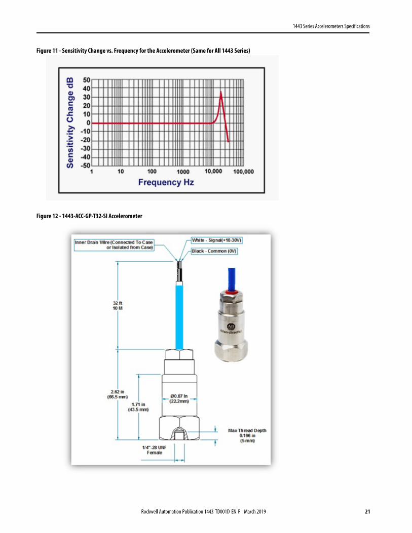
Figure 11 - Sensitivity Change vs. Frequency for the Accelerometer (Same for All 1443 Series)
Figure 12 - 1443-ACC-GP-T32-SI Accelerometer
Rockwell Automation Publication 1443-TD001D-EN-P - March 2019 21

1443 Series Accelerometers Specifications
1443-ACC-GP-T16-SC Accelerometer General-purpose industrial accelerometers are recommended for permanent installation onto machinery or route-based vibration data collection in predictive maintenance and condition-monitoring applications. Sensors with the shield wire that is grounded to the case are non-standard. See Shield Wire Isolation Sensor and Cable Selection on page 8 ordering.Table 11 - 1443-ACC-GP-T16-SC Accelerometer Specifications
Attribute ValuePerformance
Sensitivity (±5%)(1)
(1) Sensitivity tolerance is across the operating temperature range. Conversion factor 1 g = 9.81 m/s2.
10.2 mV/(m/s2) 100 mV/g
Measurement range ±785 m/s2 ±80 g
Frequency range (±5%)(2)
(2) 1 Hz = 60 cpm (cycles per minute).
1.2…10 kHz 72…600,000 cpm
Frequency range (±3 dB) 0.4…15 kHz 24…900,000 cpm
Resonant frequency, typical 28 kHz 1680 kcpm
Broadband resolution (1…10,000 Hz), typical 2943 μm/s2 300 μg
Non-linearity(3)
(3) Zero-based, least-squares, straight-line method.
±1% ±1%
Transverse sensitivity < 5% < 5%
Environmental
Overload limit (shock) 49,050 m/s2 pk 5000 g pk
Temperature range -55…+140 °C -67…+284 °F
Enclosure rating IP66 to 68, depending upon the cable assembly used. IP66 to 68, depending upon the cable assembly used.
Electrical
Settling time (within 1% of bias) < 2.0 s < 2.0 s
Discharge time constant ≥ 0.5 s ≥ 0.5 s
Excitation voltage 18…28V DC 18…28V DC
Constant current excitation 0.5…8 mA 0.5…8 mA
Output impedance <150 Ω <150 Ω
Output bias voltage 10…12V DC 10…12V DC
Electrical isolation (case) > 1010 Ω > 1010 Ω
Electrical protection 500V 500V
Physical
Size (hex x height) 19 x 36 mm 3/4 x 1.42 in.
Weight, approx. 48 g 1.7 oz
Mounting thread(4)
(4) 1/4-28 UNF has no equivalent in metric units.
M8 x 1.25 mm male 1/4-28 UNF male
Mounting torque 8 N•m 6 ft•lb
Sensing element Ceramic
Sensing geometry Compression
Housing material Stainless Steel
Sealing Welded hermetic
Electrical connector Two-pin MIL-C-5015
Electrical connector position Top
Cable Length 5 m 16 ft
Cable Type Shielded Silicone
Cable Grounding Shield Case Grounded
Supplied Accessories(5)
(5) ICS-3 3 pt calibration 10 Hz, 100 Hz, 1 kHz.
1443-STD-0-0
1443-STD-0-M8
ICS-3 3 pt calibration
22 Rockwell Automation Publication 1443-TD001D-EN-P - March 2019
1443 Series Accelerometers Specifications
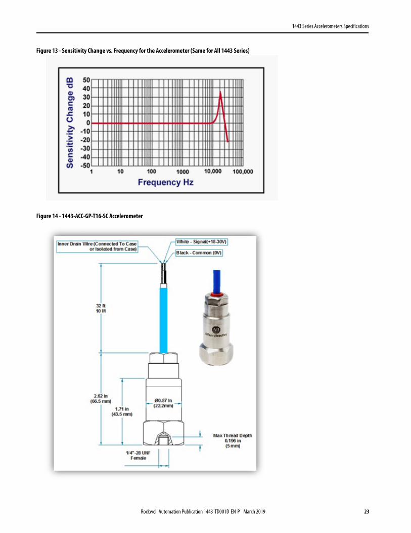
Figure 13 - Sensitivity Change vs. Frequency for the Accelerometer (Same for All 1443 Series)
Figure 14 - 1443-ACC-GP-T16-SC Accelerometer
Rockwell Automation Publication 1443-TD001D-EN-P - March 2019 23
1443 Series Accelerometers Specifications
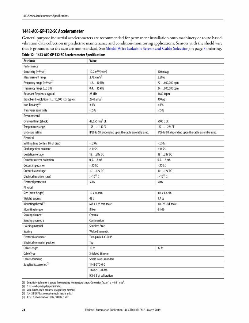
1443-ACC-GP-T32-SC AccelerometerGeneral-purpose industrial accelerometers are recommended for permanent installation onto machinery or route-based vibration data collection in predictive maintenance and condition-monitoring applications. Sensors with the shield wire that is grounded to the case are non-standard. See Shield Wire Isolation Sensor and Cable Selection on page 8 ordering.Table 12 - 1443-ACC-GP-T32-SC Accelerometer Specifications
Attribute ValuePerformance
Sensitivity (±5%)(1)
(1) Sensitivity tolerance is across the operating temperature range. Conversion factor 1 g = 9.81 m/s2.
10.2 mV/(m/s2) 100 mV/g
Measurement range ±785 m/s2 ±80 g
Frequency range (±5%)(2)
(2) 1 Hz = 60 cpm (cycles per minute).
1.2…10 kHz 72…600,000 cpm
Frequency range (±3 dB) 0.4…15 kHz 24…900,000 cpm
Resonant frequency, typical 28 kHz 1680 kcpm
Broadband resolution (1…10,000 Hz), typical 2943 μm/s2 300 μg
Non-linearity(3)
(3) Zero-based, least-squares, straight-line method.
±1% ±1%
Transverse sensitivity < 5% < 5%
Environmental
Overload limit (shock) 49,050 m/s2 pk 5000 g pk
Temperature range -55…+140 °C -67…+284 °F
Enclosure rating IP66 to 68, depending upon the cable assembly used. IP66 to 68, depending upon the cable assembly used.
Electrical
Settling time (within 1% of bias) < 2.0 s < 2.0 s
Discharge time constant ≥ 0.5 s ≥ 0.5 s
Excitation voltage 18…28V DC 18…28V DC
Constant current excitation 0.5…8 mA 0.5…8 mA
Output impedance <150 Ω <150 Ω
Output bias voltage 10…12V DC 10…12V DC
Electrical isolation (case) > 1010 Ω > 1010 Ω
Electrical protection 500V 500V
Physical
Size (hex x height) 19 x 36 mm 3/4 x 1.42 in.
Weight, approx. 48 g 1.7 oz
Mounting thread(4)
(4) 1/4-28 UNF has no equivalent in metric units.
M8 x 1.25 mm male 1/4-28 UNF male
Mounting torque 8 N•m 6 ft•lb
Sensing element Ceramic
Sensing geometry Compression
Housing material Stainless Steel
Sealing Welded hermetic
Electrical connector Two-pin MIL-C-5015
Electrical connector position Top
Cable Length 10 m 32 ft
Cable Type Shielded Silicone
Cable Grounding Shield Case Grounded
Supplied Accessories(5)
(5) ICS-3 3 pt calibration 10 Hz, 100 Hz, 1 kHz.
1443-STD-0-0
1443-STD-0-M8
ICS-3 3 pt calibration
24 Rockwell Automation Publication 1443-TD001D-EN-P - March 2019
1443 Series Accelerometers Specifications
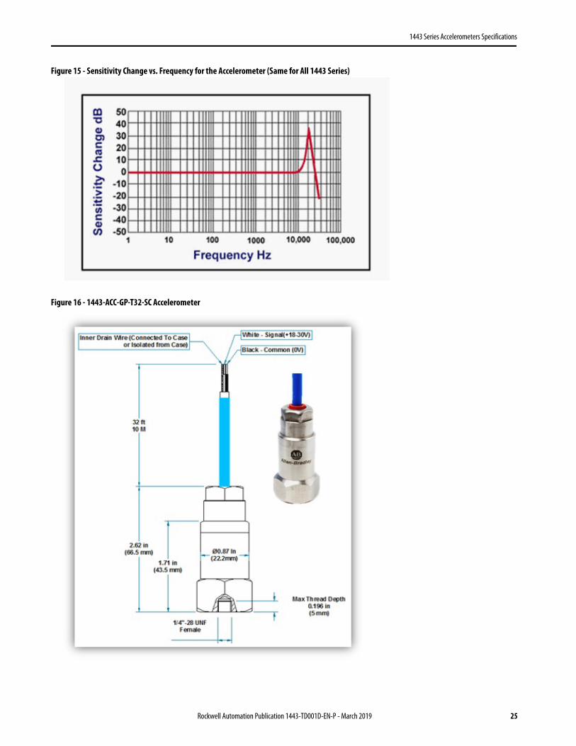
Figure 15 - Sensitivity Change vs. Frequency for the Accelerometer (Same for All 1443 Series)
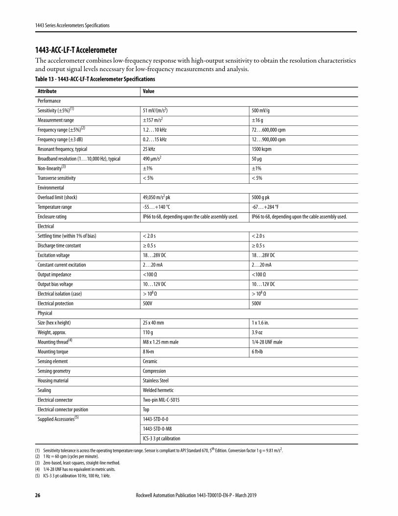
Figure 16 - 1443-ACC-GP-T32-SC Accelerometer
Rockwell Automation Publication 1443-TD001D-EN-P - March 2019 25
1443 Series Accelerometers Specifications
1443-ACC-LF-T AccelerometerThe accelerometer combines low-frequency response with high-output sensitivity to obtain the resolution characteristics and output signal levels necessary for low-frequency measurements and analysis. Table 13 - 1443-ACC-LF-T Accelerometer Specifications
Attribute Value
Performance
Sensitivity (±5%)(1)
(1) Sensitivity tolerance is across the operating temperature range. Sensor is compliant to API Standard 670, 5th Edition. Conversion factor 1 g = 9.81 m/s2.
51 mV/(m/s2) 500 mV/g
Measurement range ±157 m/s2 ±16 g
Frequency range (±5%)(2)
(2) 1 Hz = 60 cpm (cycles per minute).
1.2…10 kHz 72…600,000 cpm
Frequency range (±3 dB) 0.2…15 kHz 12…900,000 cpm
Resonant frequency, typical 25 kHz 1500 kcpm
Broadband resolution (1…10,000 Hz), typical 490 μm/s2 50 μg
Non-linearity(3)
(3) Zero-based, least-squares, straight-line method.
±1% ±1%
Transverse sensitivity < 5% < 5%
Environmental
Overload limit (shock) 49,050 m/s2 pk 5000 g pk
Temperature range -55…+140 °C -67…+284 °F
Enclosure rating IP66 to 68, depending upon the cable assembly used. IP66 to 68, depending upon the cable assembly used.
Electrical
Settling time (within 1% of bias) < 2.0 s < 2.0 s
Discharge time constant ≥ 0.5 s ≥ 0.5 s
Excitation voltage 18…28V DC 18…28V DC
Constant current excitation 2…20 mA 2…20 mA
Output impedance <100 Ω <100 Ω
Output bias voltage 10…12V DC 10…12V DC
Electrical isolation (case) > 108 Ω > 108 Ω
Electrical protection 500V 500V
Physical
Size (hex x height) 25 x 40 mm 1 x 1.6 in.
Weight, approx. 110 g 3.9 oz
Mounting thread(4)
(4) 1/4-28 UNF has no equivalent in metric units.
M8 x 1.25 mm male 1/4-28 UNF male
Mounting torque 8 N•m 6 ft•lb
Sensing element Ceramic
Sensing geometry Compression
Housing material Stainless Steel
Sealing Welded hermetic
Electrical connector Two-pin MIL-C-5015
Electrical connector position Top
Supplied Accessories(5)
(5) ICS-3 3 pt calibration 10 Hz, 100 Hz, 1 kHz.
1443-STD-0-0
1443-STD-0-M8
ICS-3 3 pt calibration
26 Rockwell Automation Publication 1443-TD001D-EN-P - March 2019
1443 Series Accelerometers Specifications
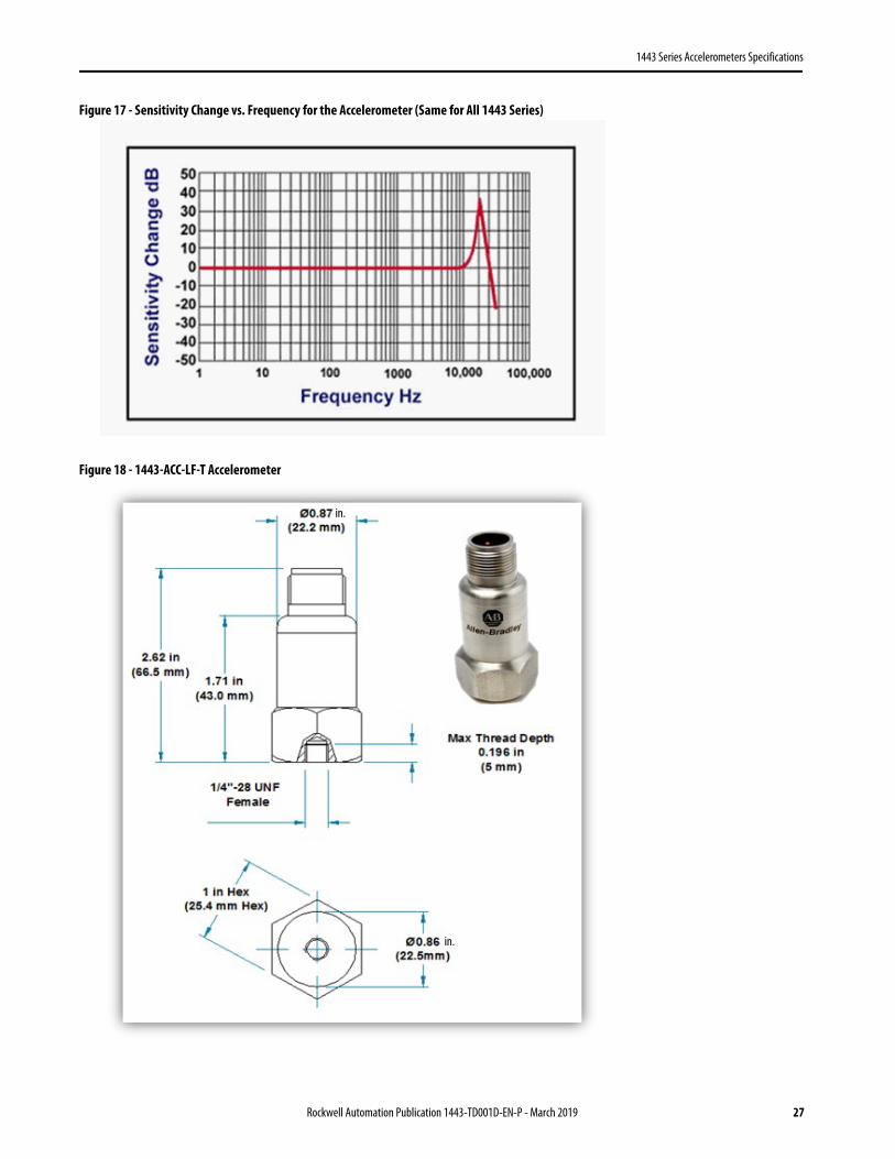
Figure 17 - Sensitivity Change vs. Frequency for the Accelerometer (Same for All 1443 Series)
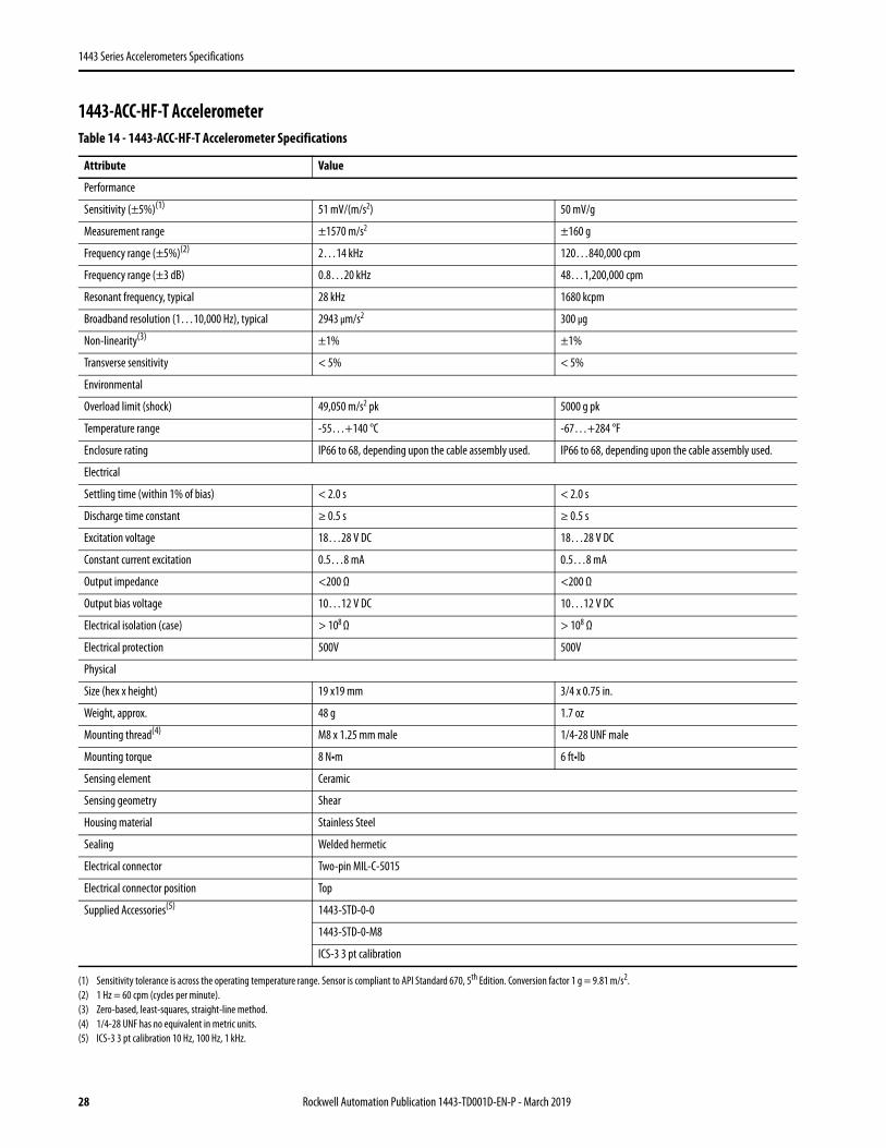
Figure 18 - 1443-ACC-LF-T Accelerometer
in.
in.
Rockwell Automation Publication 1443-TD001D-EN-P - March 2019 27
1443 Series Accelerometers Specifications
1443-ACC-HF-T AccelerometerTable 14 - 1443-ACC-HF-T Accelerometer Specifications
Attribute Value
Performance
Sensitivity (±5%)(1)
(1) Sensitivity tolerance is across the operating temperature range. Sensor is compliant to API Standard 670, 5th Edition. Conversion factor 1 g = 9.81 m/s2.
51 mV/(m/s2) 50 mV/g
Measurement range ±1570 m/s2 ±160 g
Frequency range (±5%)(2)
(2) 1 Hz = 60 cpm (cycles per minute).
2…14 kHz 120…840,000 cpm
Frequency range (±3 dB) 0.8…20 kHz 48…1,200,000 cpm
Resonant frequency, typical 28 kHz 1680 kcpm
Broadband resolution (1…10,000 Hz), typical 2943 μm/s2 300 μg
Non-linearity(3)
(3) Zero-based, least-squares, straight-line method.
±1% ±1%
Transverse sensitivity < 5% < 5%
Environmental
Overload limit (shock) 49,050 m/s2 pk 5000 g pk
Temperature range -55…+140 °C -67…+284 °F
Enclosure rating IP66 to 68, depending upon the cable assembly used. IP66 to 68, depending upon the cable assembly used.
Electrical
Settling time (within 1% of bias) < 2.0 s < 2.0 s
Discharge time constant ≥ 0.5 s ≥ 0.5 s
Excitation voltage 18…28 V DC 18…28 V DC
Constant current excitation 0.5…8 mA 0.5…8 mA
Output impedance <200 Ω <200 Ω
Output bias voltage 10…12 V DC 10…12 V DC
Electrical isolation (case) > 108 Ω > 108 Ω
Electrical protection 500V 500V
Physical
Size (hex x height) 19 x19 mm 3/4 x 0.75 in.
Weight, approx. 48 g 1.7 oz
Mounting thread(4)
(4) 1/4-28 UNF has no equivalent in metric units.
M8 x 1.25 mm male 1/4-28 UNF male
Mounting torque 8 N•m 6 ft•lb
Sensing element Ceramic
Sensing geometry Shear
Housing material Stainless Steel
Sealing Welded hermetic
Electrical connector Two-pin MIL-C-5015
Electrical connector position Top
Supplied Accessories(5)
(5) ICS-3 3 pt calibration 10 Hz, 100 Hz, 1 kHz.
1443-STD-0-0
1443-STD-0-M8
ICS-3 3 pt calibration
28 Rockwell Automation Publication 1443-TD001D-EN-P - March 2019
1443 Series Accelerometers Specifications
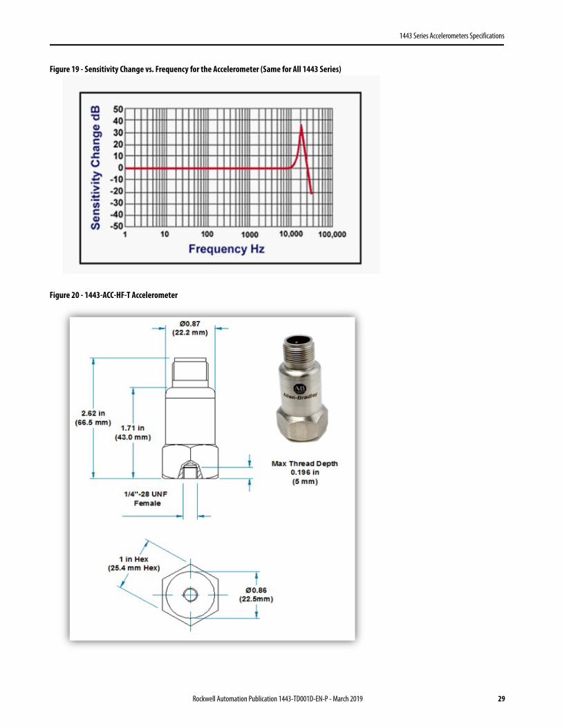
Figure 19 - Sensitivity Change vs. Frequency for the Accelerometer (Same for All 1443 Series)
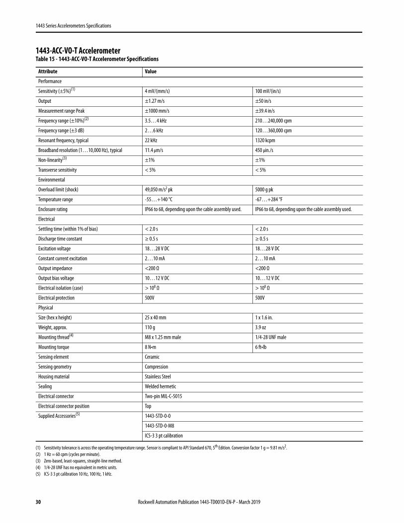
Figure 20 - 1443-ACC-HF-T Accelerometer
Rockwell Automation Publication 1443-TD001D-EN-P - March 2019 29
1443 Series Accelerometers Specifications
1443-ACC-VO-T AccelerometerTable 15 - 1443-ACC-VO-T Accelerometer Specifications
Attribute Value
Performance
Sensitivity (±5%)(1)
(1) Sensitivity tolerance is across the operating temperature range. Sensor is compliant to API Standard 670, 5th Edition. Conversion factor 1 g = 9.81 m/s2.
4 mV/(mm/s) 100 mV/(in/s)
Output ±1.27 m/s ±50 in/s
Measurement range Peak ±1000 mm/s ±39.4 in/s
Frequency range (±10%)(2)
(2) 1 Hz = 60 cpm (cycles per minute).
3.5…4 kHz 210…240,000 cpm
Frequency range (±3 dB) 2…6 kHz 120…360,000 cpm
Resonant frequency, typical 22 kHz 1320 kcpm
Broadband resolution (1…10,000 Hz), typical 11.4 μm/s 450 μin./s
Non-linearity(3)
(3) Zero-based, least-squares, straight-line method.
±1% ±1%
Transverse sensitivity < 5% < 5%
Environmental
Overload limit (shock) 49,050 m/s2 pk 5000 g pk
Temperature range -55…+140 °C -67…+284 °F
Enclosure rating IP66 to 68, depending upon the cable assembly used. IP66 to 68, depending upon the cable assembly used.
Electrical
Settling time (within 1% of bias) < 2.0 s < 2.0 s
Discharge time constant ≥ 0.5 s ≥ 0.5 s
Excitation voltage 18…28 V DC 18…28 V DC
Constant current excitation 2…10 mA 2…10 mA
Output impedance <200 Ω <200 Ω
Output bias voltage 10…12 V DC 10…12 V DC
Electrical isolation (case) > 108 Ω > 108 Ω
Electrical protection 500V 500V
Physical
Size (hex x height) 25 x 40 mm 1 x 1.6 in.
Weight, approx. 110 g 3.9 oz
Mounting thread(4)
(4) 1/4-28 UNF has no equivalent in metric units.
M8 x 1.25 mm male 1/4-28 UNF male
Mounting torque 8 N•m 6 ft•lb
Sensing element Ceramic
Sensing geometry Compression
Housing material Stainless Steel
Sealing Welded hermetic
Electrical connector Two-pin MIL-C-5015
Electrical connector position Top
Supplied Accessories(5)
(5) ICS-3 3 pt calibration 10 Hz, 100 Hz, 1 kHz.
1443-STD-0-0
1443-STD-0-M8
ICS-3 3 pt calibration
30 Rockwell Automation Publication 1443-TD001D-EN-P - March 2019
1443 Series Accelerometers Specifications
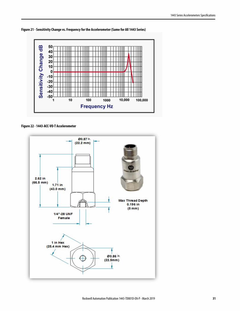
Figure 21 - Sensitivity Change vs. Frequency for the Accelerometer (Same for All 1443 Series)
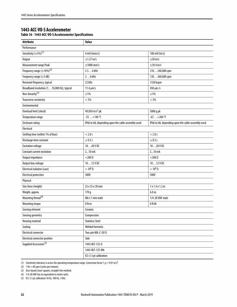
Figure 22 - 1443-ACC-VO-T Accelerometer
in.
in.
Rockwell Automation Publication 1443-TD001D-EN-P - March 2019 31
1443 Series Accelerometers Specifications
1443-ACC-VO-S Accelerometer Table 16 - 1443-ACC-VO-S Accelerometer Specifications
Attribute Value
Performance
Sensitivity (±5%)(1)
(1) Sensitivity tolerance is across the operating temperature range. Conversion factor 1 g = 9.81 m/s2.
4 mV/(mm/s) 100 mV/(in/s)
Output ±1.27 m/s ±50 in/s
Measurement range Peak ±1000 mm/s ±39.4 in/s
Frequency range (±10%)(2)
(2) 1 Hz = 60 cpm (cycles per minute).
3.5…4 kHz 210…240,000 cpm
Frequency range (±3 dB) 2…6 kHz 120…360,000 cpm
Resonant frequency, typical 22 kHz 1320 kcpm
Broadband resolution (1…10,000 Hz), typical 11.4 μm/s 450 μin./s
Non-linearity(3)
(3) Zero-based, least-squares, straight-line method.
±1% ±1%
Transverse sensitivity < 5% < 5%
Environmental
Overload limit (shock) 49,050 m/s2 pk 5000 g pk
Temperature range -55…+140 °C -67…+284 °F
Enclosure rating IP66 to 68, depending upon the cable assembly used. IP66 to 68, depending upon the cable assembly used.
Electrical
Settling time (within 1% of bias) < 2.0 s < 2.0 s
Discharge time constant ≥ 0.5 s ≥ 0.5 s
Excitation voltage 18…28 V DC 18…28 V DC
Constant current excitation 2...10 mA 2...10 mA
Output impedance <200 Ω <200 Ω
Output bias voltage 10…12 V DC 10…12 V DC
Electrical isolation (case) > 108 Ω > 108 Ω
Electrical protection 500V 500V
Physical
Size (hex x height) 25 x 35 x 30 mm 1 x 1.4 x 1.2 in
Weight, approx. 170 g 6.0 oz
Mounting thread(4)
(4) 1/4-28 UNF has no equivalent in metric units.
M6 x 1 mm male 1/4-28 UNF male
Mounting torque 8 N•m 6 ft•lb
Sensing element Ceramic
Sensing geometry Compression
Housing material Stainless Steel
Sealing Welded hermetic
Electrical connector Two-pin MIL-C-5015
Electrical connector position Side
Supplied Accessories(5)
(5) ICS-3 3 pt calibration 10 Hz, 100 Hz, 1 kHz.
1443-BLT-125-0
1443-BLT-125-M6
ICS-3 3 pt calibration
32 Rockwell Automation Publication 1443-TD001D-EN-P - March 2019
1443 Series Accelerometers Specifications
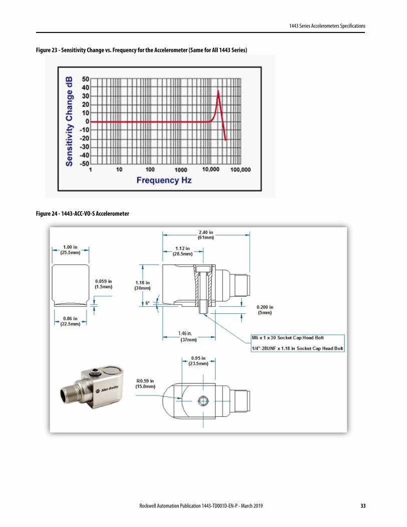
Figure 23 - Sensitivity Change vs. Frequency for the Accelerometer (Same for All 1443 Series)
Figure 24 - 1443-ACC-VO-S Accelerometer
1.46 in.
Rockwell Automation Publication 1443-TD001D-EN-P - March 2019 33
1443 Series Accelerometers Specifications
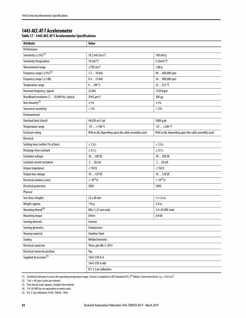
1443-ACC-AT-T Accelerometer Table 17 - 1443-ACC-AT-T Accelerometer Specifications
Attribute Value
Performance
Sensitivity (±5%)(1)
(1) Sensitivity tolerance is across the operating temperature range. Sensor is compliant to API Standard 670, 5th Edition. Conversion factor 1 g = 9.81 m/s2.
10.2 mV/(m/s2) 100 mV/g
Sensitivity Temperature 10 mV/°C 5.56mV/°F
Measurement range ±785 m/s2 ±80 g
Frequency range (±5%)(2)
(2) 1 Hz = 60 cpm (cycles per minute).
1.5…10 kHz 90…600,000 cpm
Frequency range (±3 dB) 0.4…15 kHz 24…900,000 cpm
Temperature range 0…100 °C 32…212 °F
Resonant frequency, typical 22 kHz 1320 kcpm
Broadband resolution (1…10,000 Hz), typical 2943 μm/s2 300 μg
Non-linearity(3)
(3) Zero-based, least-squares, straight-line method.
±1% ±1%
Transverse sensitivity < 5% < 5%
Environmental
Overload limit (shock) 49,050 m/s2 pk 5000 g pk
Temperature range -55…+140 °C -67…+284 °F
Enclosure rating IP66 to 68, depending upon the cable assembly used. IP66 to 68, depending upon the cable assembly used.
Electrical
Settling time (within 1% of bias) < 2.0 s < 2.0 s
Discharge time constant ≥ 0.5 s ≥ 0.5 s
Excitation voltage 18…28V DC 18…28V DC
Constant current excitation 2…20 mA 2…20 mA
Output impedance <150 Ω <150 Ω
Output bias voltage 10…12V DC 10…12V DC
Electrical isolation (case) > 1010 Ω > 1010 Ω
Electrical protection 500V 500V
Physical
Size (hex x height) 25 x 40 mm 1 x 1.6 in.
Weight, approx. 110 g 3.9 oz
Mounting thread(4)
(4) 1/4-28 UNF has no equivalent in metric units.
M8 x 1.25 mm male 1/4-28 UNF male
Mounting torque 8 N•m 6 ft•lb
Sensing element Ceramic
Sensing geometry Compression
Housing material Stainless Steel
Sealing Welded hermetic
Electrical connector Three-pin MIL-C-5015
Electrical connector position Top
Supplied Accessories(5)
(5) ICS-3 3 pt calibration 10 Hz, 100 Hz, 1 kHz.
1443-STD-0-0
1443-STD-0-M8
ICS-3 3 pt calibration
34 Rockwell Automation Publication 1443-TD001D-EN-P - March 2019
1443 Series Accelerometers Specifications
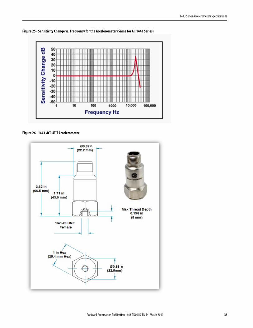
Figure 25 - Sensitivity Change vs. Frequency for the Accelerometer (Same for All 1443 Series)
Figure 26 - 1443-ACC-AT-T Accelerometer
in.
in.
Rockwell Automation Publication 1443-TD001D-EN-P - March 2019 35
1443 Series Accelerometers Specifications
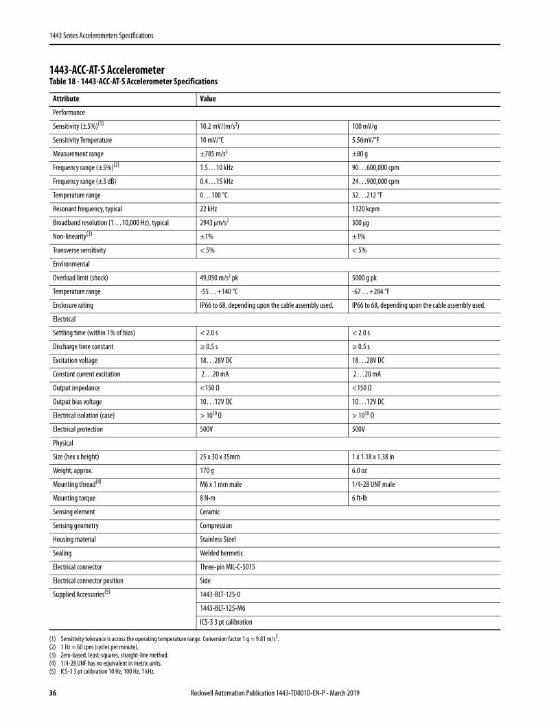
1443-ACC-AT-S AccelerometerTable 18 - 1443-ACC-AT-S Accelerometer Specifications
Attribute Value
Performance
Sensitivity (±5%)(1)
(1) Sensitivity tolerance is across the operating temperature range. Conversion factor 1 g = 9.81 m/s2.
10.2 mV/(m/s2) 100 mV/g
Sensitivity Temperature 10 mV/°C 5.56mV/°F
Measurement range ±785 m/s2 ±80 g
Frequency range (±5%)(2)
(2) 1 Hz = 60 cpm (cycles per minute).
1.5…10 kHz 90…600,000 cpm
Frequency range (±3 dB) 0.4…15 kHz 24…900,000 cpm
Temperature range 0…100 °C 32…212 °F
Resonant frequency, typical 22 kHz 1320 kcpm
Broadband resolution (1…10,000 Hz), typical 2943 μm/s2 300 μg
Non-linearity(3)
(3) Zero-based, least-squares, straight-line method.
±1% ±1%
Transverse sensitivity < 5% < 5%
Environmental
Overload limit (shock) 49,050 m/s2 pk 5000 g pk
Temperature range -55…+140 °C -67…+284 °F
Enclosure rating IP66 to 68, depending upon the cable assembly used. IP66 to 68, depending upon the cable assembly used.
Electrical
Settling time (within 1% of bias) < 2.0 s < 2.0 s
Discharge time constant ≥ 0.5 s ≥ 0.5 s
Excitation voltage 18…28V DC 18…28V DC
Constant current excitation 2…20 mA 2…20 mA
Output impedance <150 Ω <150 Ω
Output bias voltage 10…12V DC 10…12V DC
Electrical isolation (case) > 1010 Ω > 1010 Ω
Electrical protection 500V 500V
Physical
Size (hex x height) 25 x 30 x 35mm 1 x 1.18 x 1.38 in
Weight, approx. 170 g 6.0 oz
Mounting thread(4)
(4) 1/4-28 UNF has no equivalent in metric units.
M6 x 1 mm male 1/4-28 UNF male
Mounting torque 8 N•m 6 ft•lb
Sensing element Ceramic
Sensing geometry Compression
Housing material Stainless Steel
Sealing Welded hermetic
Electrical connector Three-pin MIL-C-5015
Electrical connector position Side
Supplied Accessories(5)
(5) ICS-3 3 pt calibration 10 Hz, 100 Hz, 1 kHz.
1443-BLT-125-0
1443-BLT-125-M6
ICS-3 3 pt calibration
36 Rockwell Automation Publication 1443-TD001D-EN-P - March 2019

1443 Series Accelerometers Specifications
Figure 27 - Sensitivity Change vs. Frequency for the Accelerometer (Same for All 1443 Series)
Figure 28 - 1443-ACC-AT-S Accelerometer
1.46 in.
Rockwell Automation Publication 1443-TD001D-EN-P - March 2019 37

1443 Series Accelerometers Specifications
1443-ACC-IS-T Accelerometer Table 19 - 1443-ACC-IS-T Accelerometer Specifications
Attribute Value
Performance
Sensitivity (±5%)(1)
(1) Sensitivity tolerance is across the operating temperature range. Sensor is compliant to API Standard 670, 5th Edition. Conversion factor 1 g = 9.81 m/s2.
10.2 mV/(m/s2) 100 mV/g
Measurement range ±785 m/s2 ±80 g
Frequency range (±5%)(2)
(2) 1 Hz = 60 cpm (cycles per minute).
1.5…10 kHz 90…600,000 cpm
Frequency range (±3 dB) 0.4…15 kHz 24…900,000 cpm
Resonant frequency, typical 28 kHz 1680 kcpm
Broadband resolution (1…10,000 Hz), typical 2943 μm/s2 300 μg
Non-linearity(3)
(3) Zero-based, least-squares, straight-line method.
±1% ±1%
Transverse sensitivity < 5% < 5%
Environmental
Overload limit (shock) 49,050 m/s2 pk 5000 g pk
Temperature range -55…+110 °C -67…+230 °F
Enclosure rating IP66 to 68, depending upon the cable assembly used. IP66 to 68, depending upon the cable assembly used.
Electrical
Settling time (within 1% of bias) < 2.0 s < 2.0 s
Discharge time constant ≥ 0.5 s ≥ 0.5 s
Excitation voltage 18…28V DC 18…28V DC
Constant current excitation 2…20 mA 2…20 mA
Output impedance <150 Ω <150 Ω
Output bias voltage 10…12V DC 10…12V DC
Electrical isolation (case) > 1010 Ω > 1010 Ω
Electrical protection 500V 500V
Physical
Size (hex x height) 19 x36 mm 3/4 x 1.42 in.
Weight, approx. 48 g 1.7 oz
Mounting thread(4)
(4) 1/4-28 UNF has no equivalent in metric units.
M8 x 1.25 mm male 1/4-28 UNF male
Mounting torque 8 N•m 6 ft•lb
Sensing element Ceramic
Sensing geometry Compression
Housing material Stainless Steel
Sealing Welded hermetic
Electrical connector Two-pin MIL-C-5015
Electrical connector position Top
Supplied Accessories(5)
(5) ICS-3 3 pt calibration 10 Hz, 100 Hz, 1 kHz.
1443-STD-0-0
1443-STD-0-M8
ICS-3 3 pt calibration
38 Rockwell Automation Publication 1443-TD001D-EN-P - March 2019
1443 Series Accelerometers Specifications
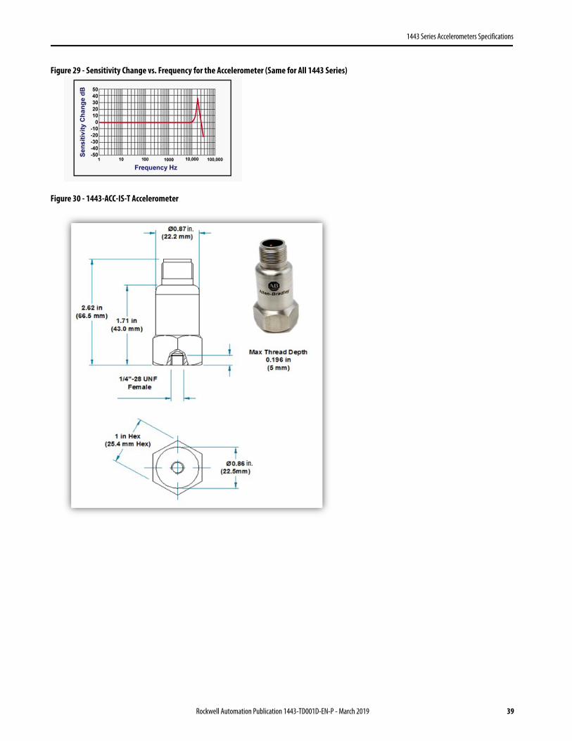
Figure 29 - Sensitivity Change vs. Frequency for the Accelerometer (Same for All 1443 Series)
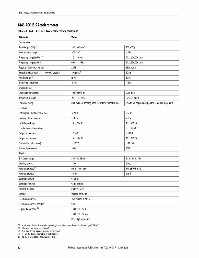
Figure 30 - 1443-ACC-IS-T Accelerometer
in.
in.
Rockwell Automation Publication 1443-TD001D-EN-P - March 2019 39
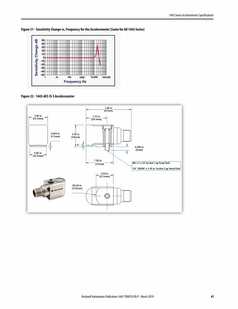
1443 Series Accelerometers Specifications
1443-ACC-IS-S Accelerometer Table 20 - 1443--ACC-IS-S Accelerometer Specifications
Attribute Value
Performance
Sensitivity (±5%)(1)
(1) Sensitivity tolerance is across the operating temperature range. Conversion factor 1 g = 9.81 m/s2.
10.2 mV/(m/s2) 100 mV/g
Measurement range ±785 m/s2 ±80 g
Frequency range (±5%)(2)
(2) 1 Hz = 60 cpm (cycles per minute).
1.5…10 kHz 90…600,000 cpm
Frequency range (±3 dB) 0.84…15 kHz 24…900,000 cpm
Resonant frequency, typical 22 kHz 1500 kcpm
Broadband resolution (1…10,000 Hz), typical 491 μm/s2 50 μg
Non-linearity(3)
(3) Zero-based, least-squares, straight-line method.
±1% ±1%
Transverse sensitivity < 5% < 5%
Environmental
Overload limit (shock) 49,050 m/s2 pk 5000 g pk
Temperature range -55…+110 °C -67…+230 °F
Enclosure rating IP66 to 68, depending upon the cable assembly used. IP66 to 68, depending upon the cable assembly used.
Electrical
Settling time (within 1% of bias) < 2.0 s < 2.0 s
Discharge time constant ≥ 0.5 s ≥ 0.5 s
Excitation voltage 18…28V DC 18…28V DC
Constant current excitation … 2…20 mA
Output impedance <150 Ω <150 Ω
Output bias voltage 10…12V DC 10…12V DC
Electrical isolation (case) > 1010 Ω > 1010 Ω
Electrical protection 500V 500V
Physical
Size (hex x height) 25 x 30 x 35 mm 1 x 1.18 x 1.38 in
Weight, approx. 170 g 6.0 oz
Mounting thread(4)
(4) 1/4-28 UNF has no equivalent in metric units.
M6 x 1 mm male 1/4-28 UNF male
Mounting torque 8 N•m 6 ft•lb
Sensing element Ceramic
Sensing geometry Compression
Housing material Stainless Steel
Sealing Welded hermetic
Electrical connector Two-pin MIL-C-5015
Electrical connector position Side
Supplied Accessories(5)
(5) ICS-3 3 pt calibration 10 Hz, 100 Hz, 1 kHz.
1443-BLT-125-0
1443-BLT-125-M6
ICS-3 3 pt calibration
40 Rockwell Automation Publication 1443-TD001D-EN-P - March 2019
1443 Series Accelerometers Specifications
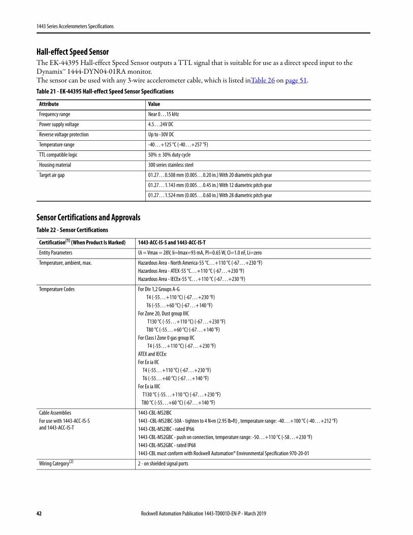
Figure 31 - Sensitivity Change vs. Frequency for the Accelerometer (Same for All 1443 Series)
Figure 32 - 1443-ACC-IS-S Accelerometer
1.46 in.
Rockwell Automation Publication 1443-TD001D-EN-P - March 2019 41
1443 Series Accelerometers Specifications
Hall-effect Speed SensorThe EK-44395 Hall-effect Speed Sensor outputs a TTL signal that is suitable for use as a direct speed input to the Dynamix™ 1444-DYN04-01RA monitor.The sensor can be used with any 3-wire accelerometer cable, which is listed inTable 26 on page 51.
Sensor Certifications and Approvals
Table 21 - EK-44395 Hall-effect Speed Sensor Specifications
Attribute Value
Frequency range Near 0…15 kHz
Power supply voltage 4.5…24V DC
Reverse voltage protection Up to -30V DC
Temperature range -40…+125 °C (-40…+257 °F)
TTL compatible logic 50% ± 30% duty cycle
Housing material 300 series stainless steel
Target air gap
01.27…0.508 mm (0.005…0.20 in.) With 20 diametric pitch gear
01.27…1.143 mm (0.005…0.45 in.) With 12 diametric pitch gear
01.27…1.524 mm (0.005…0.60 in.) With 28 diametric pitch gear
Table 22 - Sensor Certifications
Certification(1) (When Product Is Marked) 1443-ACC-IS-S and 1443-ACC-IS-T
Entity Parameters Ui = Vmax = 28V, Ii=lmax=93 mA, PI=0.65 W, CI=1.0 nF, Li=zero
Temperature, ambient, max. Hazardous Area - North America-55 °C…+110 °C (-67…+230 °F)Hazardous Area - ATEX-55 °C…+110 °C (-67…+230 °F)Hazardous Area - IECEx-55 °C…+110 °C (-67…+230 °F)
Temperature Codes For Div 1,2 Groups A-G T4 (-55…+110 °C) (-67…+230 °F) T6 (-55…+60 °C) (-67…+140 °F)For Zone 20, Dust group IIIC T130 °C (-55…+110 °C) (-67…+230 °F) T80 °C (-55…+60 °C) (-67…+140 °F)For Class I Zone 0 gas group IIC T4 (-55…+110 °C) (-67…+230 °F)ATEX and IECEx:For Ex ia IIC T4 (-55…+110 °C) (-67…+230 °F) T6 (-55…+60 °C) (-67…+140 °F)For Ex ia IIIC T130 °C (-55…+110 °C) (-67…+230 °F) T80 °C (-55…+60 °C) (-67…+140 °F)
Cable AssembliesFor use with 1443-ACC-IS-S and 1443-ACC-IS-T
1443-CBL-MS2IBC1443 -CBL-MS2IBC-50A - tighten to 4 N•m (2.95 lb•ft) , temperature range: -40…+100 °C (-40…+212 °F)1443-CBL-MS2IBC - rated IP661443-CBL-MS2GBC - push on connection, temperature range: -50…+110 °C (-58…+230 °F)1443-CBL-MS2GBC - rated IP681443-CBL must conform with Rockwell Automation® Environmental Specification 970-20-01
Wiring Category(2) 2 - on shielded signal ports
42 Rockwell Automation Publication 1443-TD001D-EN-P - March 2019

1443 Series Accelerometers Specifications
Ex European Union 94/9/EC ATEX Directive, compliant with:EN 60079-0:2010+A11:2013; General RequirementsEN 60079-11:2012 Explosive Atmospheres, Protection `i’
I M1 Ex ia I Ma -55 °C<Ta<+110 °C (-67…+230 °F)II 1 G Ex ia IIC T4 Ga -55 °C <Ta<+110 °C (-67…+230 °F)II 1 G Ex ia IIC T6 Ga -55 °C <Ta<+60 °C (-67…+140 °F)II 1 D Ex ia IIIC T130°C IP65 Da -55 °C <Ta<+110 °C (-67…+230 °F)II 1 D Ex ia IIIC T80°C IP65 Da -55 °C <Ta<+60 °C (-67…+140 °F)
Baseefa15ATEX0101XBaseefa15ATEX0100
IECEx IECEx System, compliant with:IEC 60079-0:2011 Edition 6; General RequirementsIEC 60079-11:2011 Edition 6; Explosive Atmospheres, Protection `i‘Ex ia I Ma -55 °C<Ta<+110 °C (-67…+230 °F) Ex ia IIC T4 Ga -55 °C<Ta<+110 °C (-67…+230 °F)Ex ia IIC T6 Ga -55 °C<Ta<+60 °C (-67…+140 °F)Ex ia IIIC T130°C IP65 Da -55 °C <Ta<+110 °C (-67…+230 °F)Ex ia IIIC T80°C IP65 Da -55 °C <Ta<+60 °C (-67…+140 °F)IECEx BAS 15.0073XIECEx BAS 15.0072
c-SGS-us SGS Certified Process Control Equipment for Class I, Zone 0 Hazardous Locations, which are certified for US and Canada. See SGS File USTC/15/FAI/01350AEx, ia, IIC, T4, Ga, -55°C…+110 °C (-67…+230 °F)
c-SGS-us SGS Certified Process Control Equipment for Zone 20Hazardous Locations, which are certified for US and Canada. See SGS File USTC/15/FAI/01350AEx, ia, IIIC, T130°C, IP65, Da, -55 °C…+110 °CAEx, ia, IIIC, T80°C, IP65, Da, -55 °C…+60 °C
c-SGS-us SGS Certified Process Control Equipment for Class I, II, III Division 1, 2 Group A-GHazardous Locations, which are certified for US and Canada. See SGS File USTC/15/FAI/01350T4, -55 °C…+110 °C, IP65T6, -55 °C…+60 °C
(1) See the Product Certification link at www.ab.com for Declarations of Conformity, Certificates, and other certification details.
(2) Use this conductor category information to plan conductor routing. See Industrial Automation Wiring and Grounding Guidelines, publication 1770-4.1.
Table 22 - Sensor Certifications (Continued)
Rockwell Automation Publication 1443-TD001D-EN-P - March 2019 43
1443 Series Accelerometers Specifications
Accessories
This section describes the accessories that are available for the sensors.
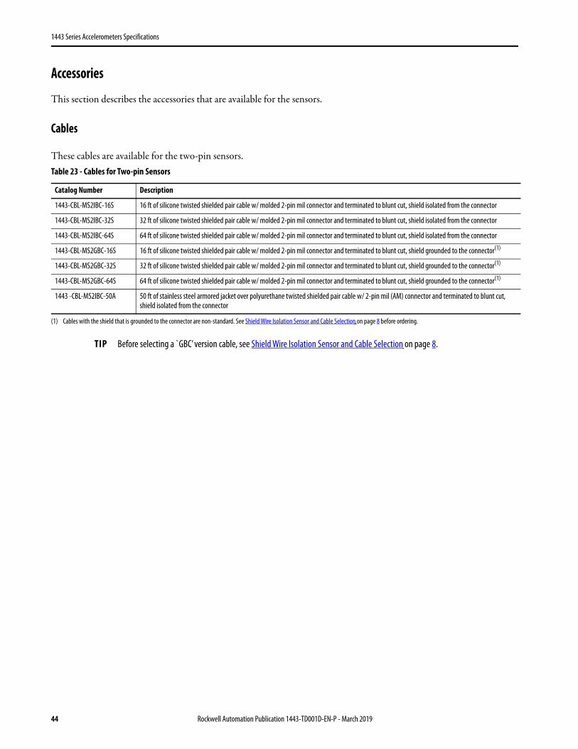
Cables
These cables are available for the two-pin sensors.Table 23 - Cables for Two-pin Sensors
Catalog Number Description
1443-CBL-MS2IBC-16S 16 ft of silicone twisted shielded pair cable w/ molded 2-pin mil connector and terminated to blunt cut, shield isolated from the connector
1443-CBL-MS2IBC-32S 32 ft of silicone twisted shielded pair cable w/ molded 2-pin mil connector and terminated to blunt cut, shield isolated from the connector
1443-CBL-MS2IBC-64S 64 ft of silicone twisted shielded pair cable w/ molded 2-pin mil connector and terminated to blunt cut, shield isolated from the connector
1443-CBL-MS2GBC-16S 16 ft of silicone twisted shielded pair cable w/ molded 2-pin mil connector and terminated to blunt cut, shield grounded to the connector(1)
(1) Cables with the shield that is grounded to the connector are non-standard. See Shield Wire Isolation Sensor and Cable Selection on page 8 before ordering.
1443-CBL-MS2GBC-32S 32 ft of silicone twisted shielded pair cable w/ molded 2-pin mil connector and terminated to blunt cut, shield grounded to the connector(1)
1443-CBL-MS2GBC-64S 64 ft of silicone twisted shielded pair cable w/ molded 2-pin mil connector and terminated to blunt cut, shield grounded to the connector(1)
1443 -CBL-MS2IBC-50A 50 ft of stainless steel armored jacket over polyurethane twisted shielded pair cable w/ 2-pin mil (AM) connector and terminated to blunt cut, shield isolated from the connector
TIP Before selecting a `GBC’ version cable, see Shield Wire Isolation Sensor and Cable Selection on page 8.
44 Rockwell Automation Publication 1443-TD001D-EN-P - March 2019
1443 Series Accelerometers Specifications
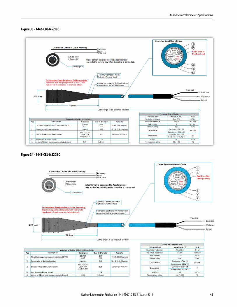
Figure 33 - 1443-CBL-MS2IBC
Figure 34 - 1443-CBL-MS2GBC
Rockwell Automation Publication 1443-TD001D-EN-P - March 2019 45
1443 Series Accelerometers Specifications
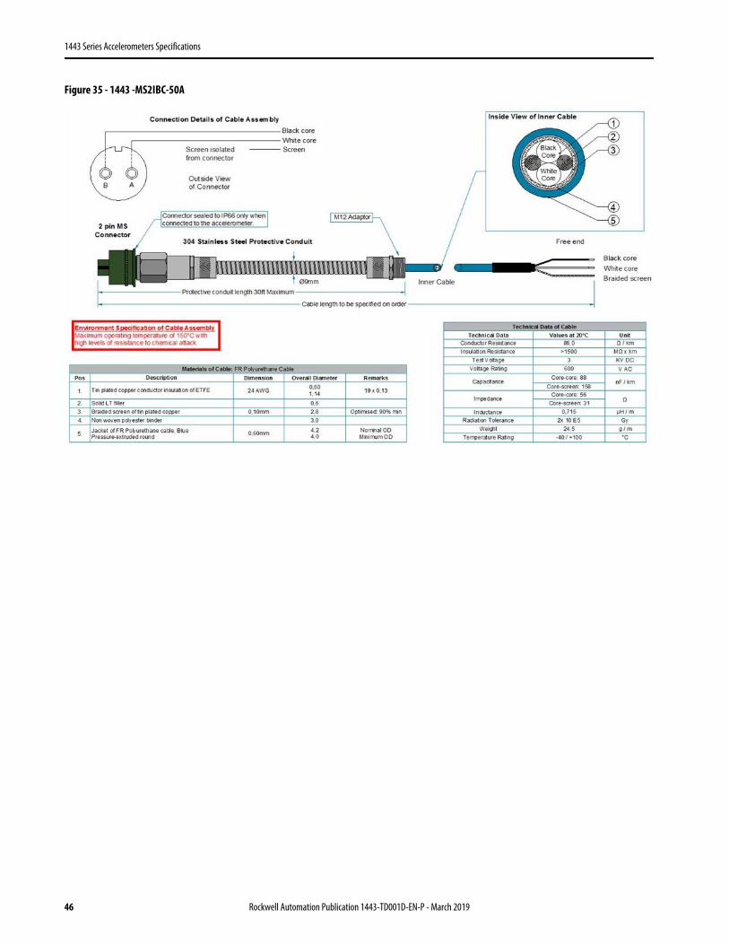
Figure 35 - 1443 -MS2IBC-50A
46 Rockwell Automation Publication 1443-TD001D-EN-P - March 2019
1443 Series Accelerometers Specifications
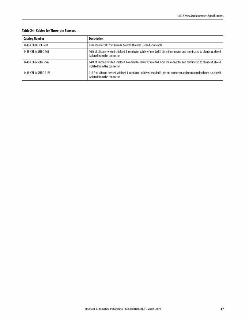
Table 24 - Cables for Three-pin Sensors
Catalog Number Description
1443-CBL-BC3BC-500 Bulk spool of 500 ft of silicone twisted shielded 3-conductor cable
1443-CBL-MS3IBC-16S 16 ft of silicone twisted shielded 3-conductor cable w/ molded 3-pin mil connector and terminated to blunt cut, shield isolated from the connector
1443-CBL-MS3IBC-64S 64 ft of silicone twisted shielded 3-conductor cable w/ molded 3-pin mil connector and terminated to blunt cut, shield isolated from the connector
1443-CBL-MS3IBC-112S 112 ft of silicone twisted shielded 3-conductor cable w/ molded 3-pin mil connector and terminated to blunt cut, shield isolated from the connector
Rockwell Automation Publication 1443-TD001D-EN-P - March 2019 47

1443 Series Accelerometers Specifications
Figure 36 - 1443-CBL-BC3BC-500
Figure 37 - 1443-CBL-MS3IBC (All Lengths)
48 Rockwell Automation Publication 1443-TD001D-EN-P - March 2019
1443 Series Accelerometers Specifications
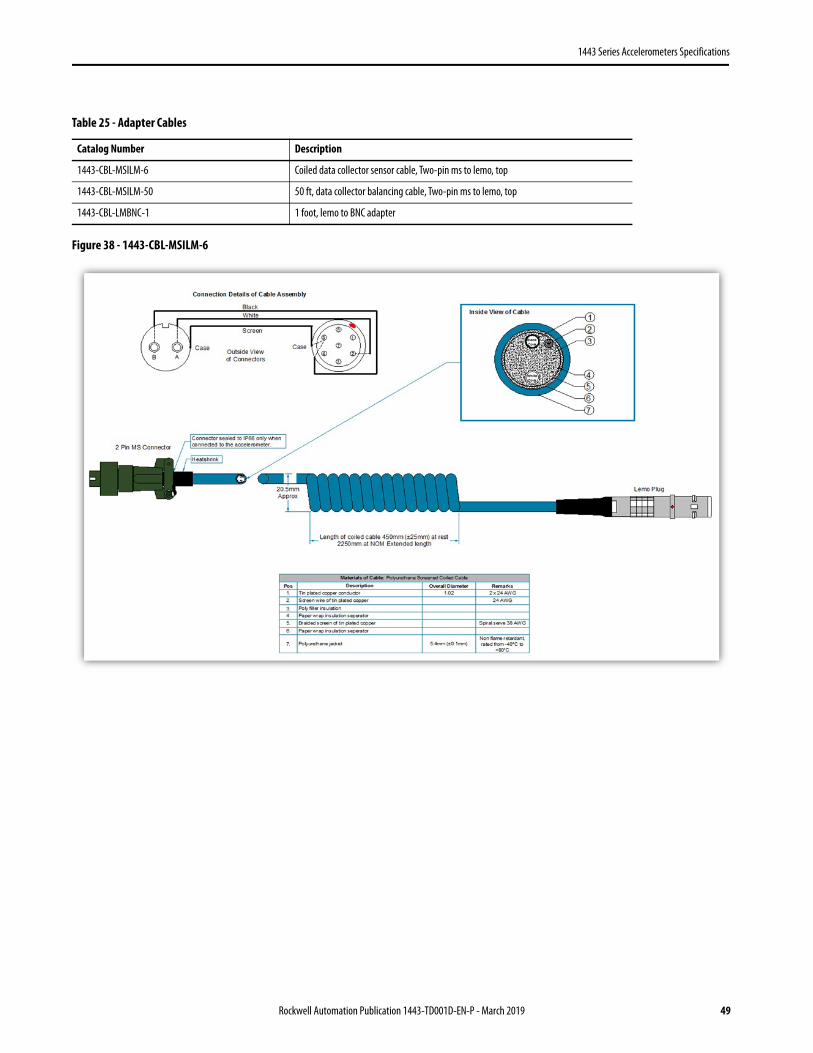
Figure 38 - 1443-CBL-MSILM-6
Table 25 - Adapter Cables
Catalog Number Description
1443-CBL-MSILM-6 Coiled data collector sensor cable, Two-pin ms to lemo, top
1443-CBL-MSILM-50 50 ft, data collector balancing cable, Two-pin ms to lemo, top
1443-CBL-LMBNC-1 1 foot, lemo to BNC adapter
Rockwell Automation Publication 1443-TD001D-EN-P - March 2019 49

1443 Series Accelerometers Specifications
Figure 39 - 1443-CBL-MSILM-50
Figure 40 - 1443-CBL-LMBNC-1
50 Rockwell Automation Publication 1443-TD001D-EN-P - March 2019
1443 Series Accelerometers Specifications
Connectors
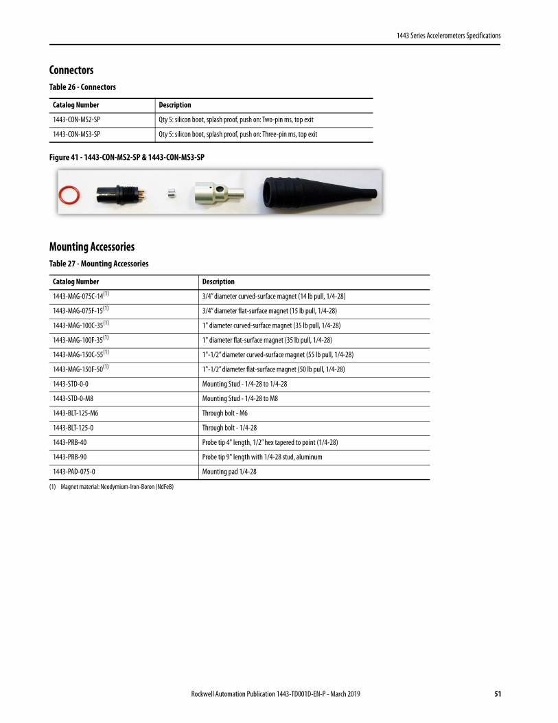
Figure 41 - 1443-CON-MS2-SP & 1443-CON-MS3-SP
Mounting Accessories
Table 26 - Connectors
Catalog Number Description
1443-CON-MS2-SP Qty 5: silicon boot, splash proof, push on: Two-pin ms, top exit
1443-CON-MS3-SP Qty 5: silicon boot, splash proof, push on: Three-pin ms, top exit
Table 27 - Mounting Accessories
Catalog Number Description
1443-MAG-075C-14(1)
(1) Magnet material: Neodymium-Iron-Boron (NdFeB)
3/4” diameter curved-surface magnet (14 lb pull, 1/4-28)
1443-MAG-075F-15(1) 3/4” diameter flat-surface magnet (15 lb pull, 1/4-28)
1443-MAG-100C-35(1) 1" diameter curved-surface magnet (35 lb pull, 1/4-28)
1443-MAG-100F-35(1) 1" diameter flat-surface magnet (35 lb pull, 1/4-28)
1443-MAG-150C-55(1) 1"-1/2” diameter curved-surface magnet (55 lb pull, 1/4-28)
1443-MAG-150F-50(1) 1"-1/2” diameter flat-surface magnet (50 lb pull, 1/4-28)
1443-STD-0-0 Mounting Stud - 1/4-28 to 1/4-28
1443-STD-0-M8 Mounting Stud - 1/4-28 to M8
1443-BLT-125-M6 Through bolt - M6
1443-BLT-125-0 Through bolt - 1/4-28
1443-PRB-40 Probe tip 4" length, 1/2” hex tapered to point (1/4-28)
1443-PRB-90 Probe tip 9" length with 1/4-28 stud, aluminum
1443-PAD-075-0 Mounting pad 1/4-28
Rockwell Automation Publication 1443-TD001D-EN-P - March 2019 51
1443 Series Accelerometers Specifications
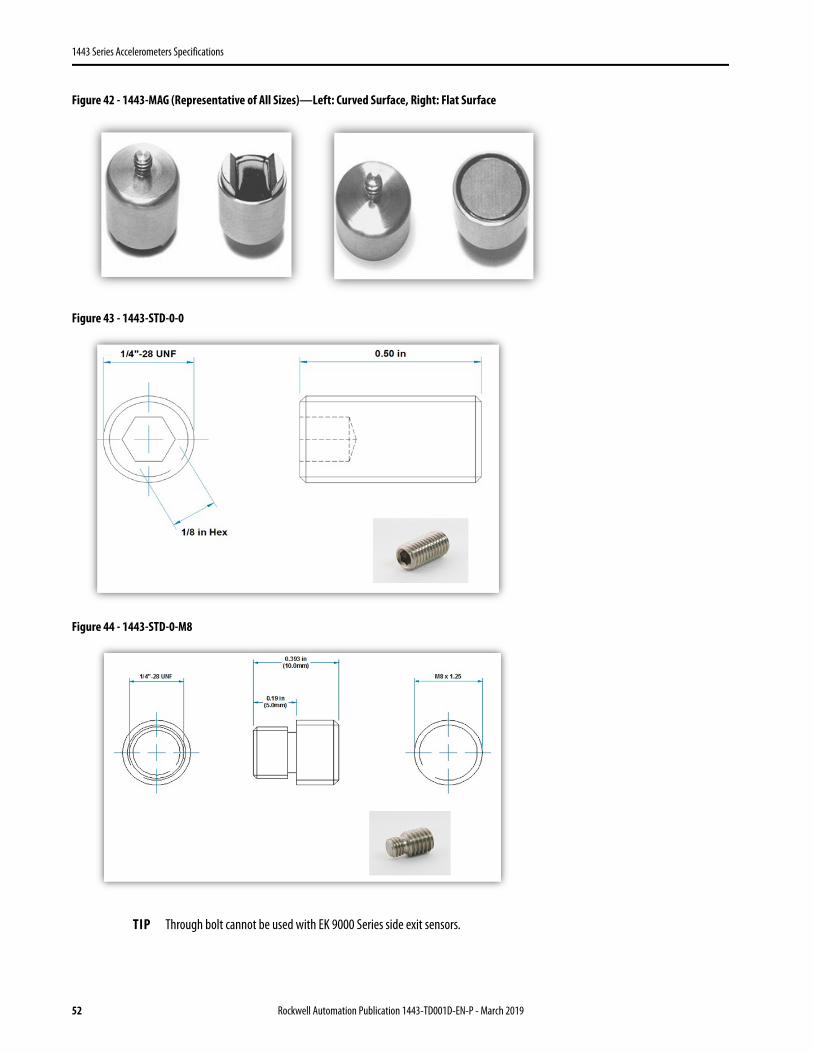
Figure 42 - 1443-MAG (Representative of All Sizes)—Left: Curved Surface, Right: Flat Surface
Figure 43 - 1443-STD-0-0
Figure 44 - 1443-STD-0-M8
TIP Through bolt cannot be used with EK 9000 Series side exit sensors.
52 Rockwell Automation Publication 1443-TD001D-EN-P - March 2019
1443 Series Accelerometers Specifications
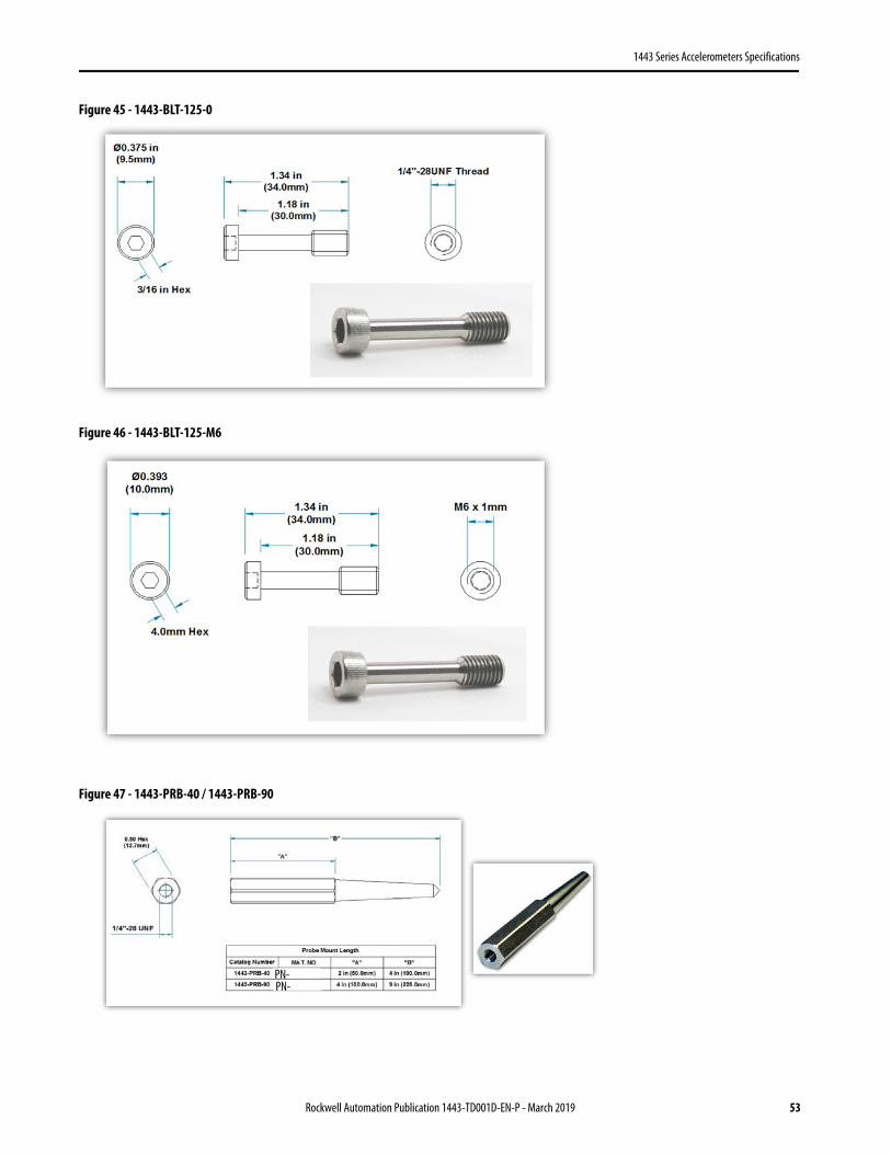
Figure 45 - 1443-BLT-125-0
Figure 46 - 1443-BLT-125-M6
Figure 47 - 1443-PRB-40 / 1443-PRB-90
PN-PN-
Rockwell Automation Publication 1443-TD001D-EN-P - March 2019 53

1443 Series Accelerometers Specifications
Figure 48 - 1443-PAD
Spot-face Tool Kits
Figure 49 - 1443-SFT-125 (Representative for All)
Table 28 - Accessory Spot-face Tool Kit
Catalog Number Description
1443-SFT-125-0 Spot-face tool kit for sensor mounting, 1.25" diameter, 1/4-28 pilot, two drill Bits, three taps, tap wrench, hex key, case
1443-SFT-125-M6 Spot-face tool kit for sensor mounting, M6 pilot, two drill Bits, three taps, tap wrench, hex key, case
1443-SFT-125-M8 Spot-face tool kit for sensor mounting, M8 pilot, two drill Bits, three taps, tap wrench, hex key, case
54 Rockwell Automation Publication 1443-TD001D-EN-P - March 2019
1443 Series Accelerometers Specifications
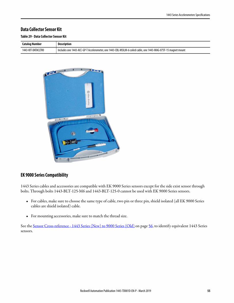
Data Collector Sensor Kit
EK 9000 Series Compatibility
1443 Series cables and accessories are compatible with EK 9000 Series sensors except for the side exist sensor through bolts. Through bolts 1443-BLT-125-M6 and 1443-BLT-125-0 cannot be used with EK 9000 Series sensors.
• For cables, make sure to choose the same type of cable, two pin or three pin, shield isolated (all EK 9000 Series cables are shield isolated) cable.
• For mounting accessories, make sure to match the thread size.
See the Sensor Cross-reference - 1443 Series (New) to 9000 Series (Old) on page 56, to identify equivalent 1443 Series sensors.
Table 29 - Data Collector Sensor Kit
Catalog Number Description
1443-KIT-DATACLTR0 Includes one 1443-ACC-GP-T Accelerometer, one 1443-CBL-MSILM-6 coiled cable, one 1443-MAG-075F-15 magnet mount
Rockwell Automation Publication 1443-TD001D-EN-P - March 2019 55
1443 Series Accelerometers Specifications
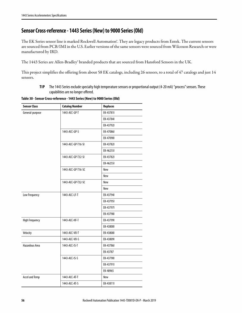
Sensor Cross-reference - 1443 Series (New) to 9000 Series (Old)
The EK Series sensor line is marked Rockwell Automation®. They are legacy products from Entek. The current sensors are sourced from PCB/IMI in the U.S. Earlier versions of the same sensors were sourced from Wilcoxon Research or were manufactured by IRD.
The 1443 Series are Allen-Bradley® branded products that are sourced from Hansford Sensors in the UK.
This project simplifies the offering from about 58 EK catalogs, including 26 sensors, to a total of 47 catalogs and just 14 sensors.
TIP The 1443 Series exclude specialty high temperature sensors or proportional output (4-20 mA) “process” sensors. These capabilities are no longer offered.
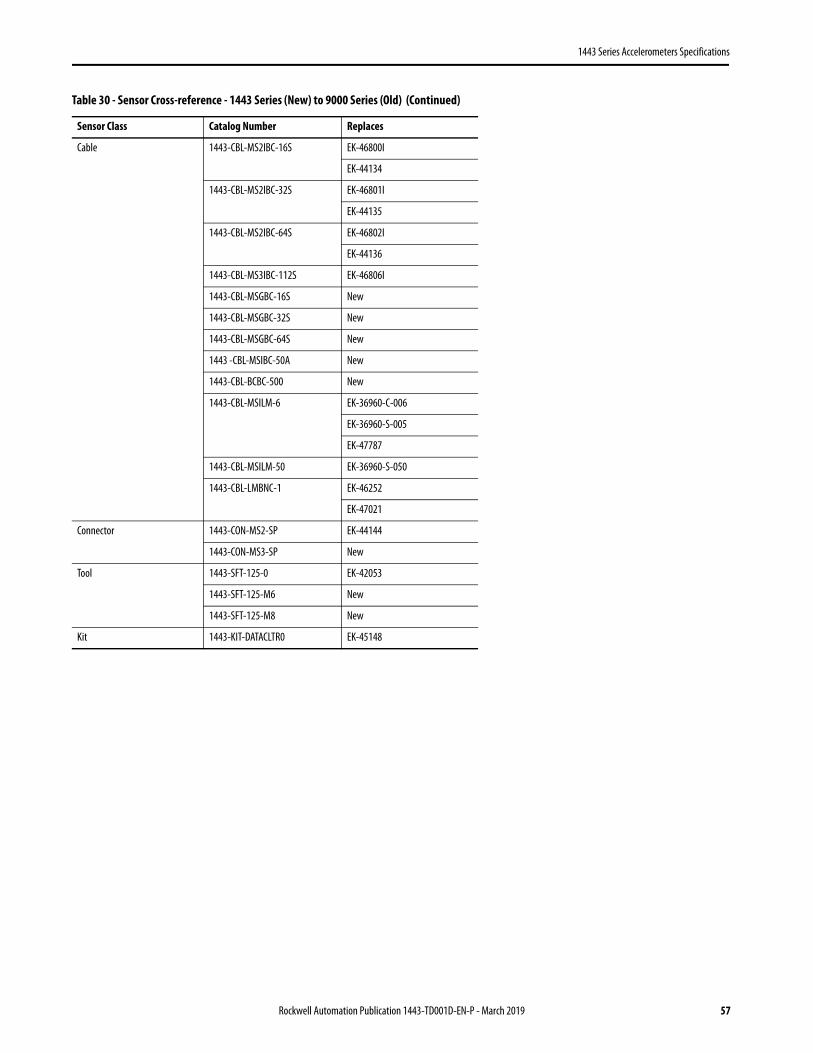
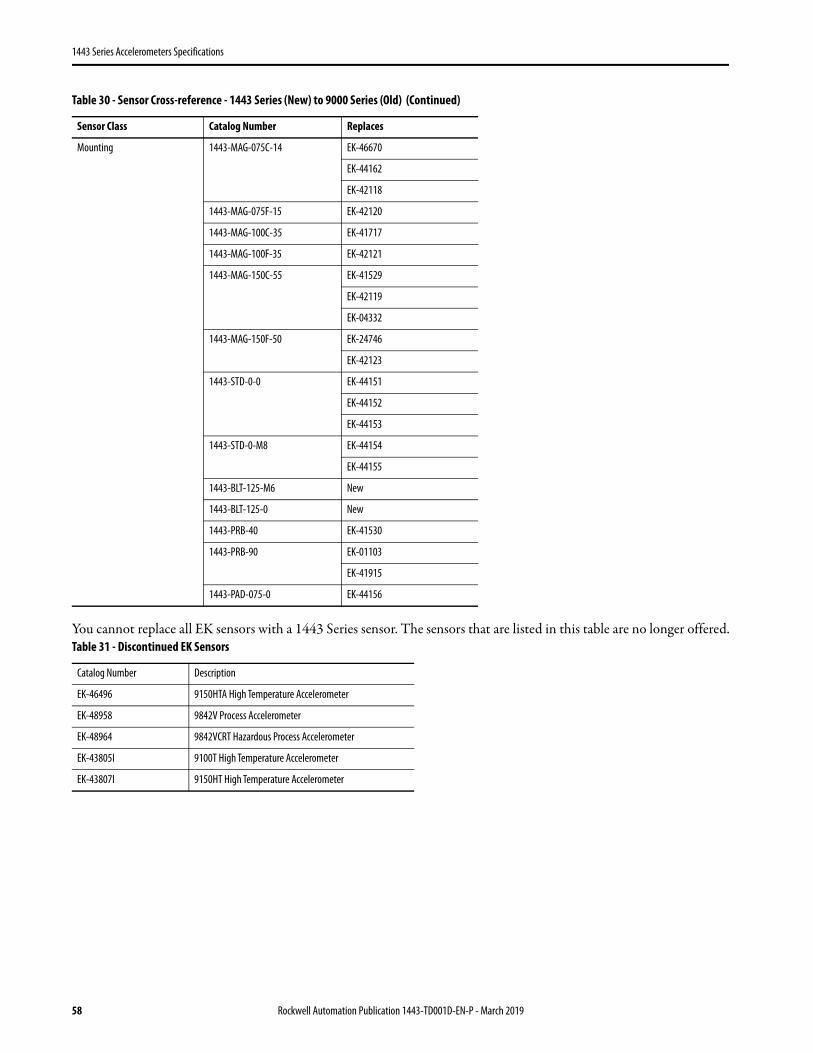
Table 30 - Sensor Cross-reference - 1443 Series (New) to 9000 Series (Old)
Sensor Class Catalog Number Replaces
General-purpose 1443-ACC-GP-T EK-43781I
EK-43784I
EK-43792I
1443-ACC-GP-S EK-47086I
EK-47090I
1443-ACC-GP-T16-SI EK-43782I
EK-46255I
1443-ACC-GP-T32-SI EK-43782I
EK-46255I
1443-ACC-GP-T16-SC New
New
1443-ACC-GP-T32-SC New
New
Low Frequency 1443-ACC-LF-T EK-43794I
EK-43795I
EK-43797I
EK-43798I
High Frequency 1443-ACC-HF-T EK-43799I
EK-43800I
Velocity 1443-ACC-VO-T EK-43808I
1443-ACC-VO-S EK-43809I
Hazardous Area 1443-ACC-IS-T EK-43786I
EK-43787
1443-ACC-IS-S EK-43790I
EK-43791I
EK-48965
Accel and Temp 1443-ACC-AT-T New
1443-ACC-AT-S EK-43811I
56 Rockwell Automation Publication 1443-TD001D-EN-P - March 2019
1443 Series Accelerometers Specifications
Cable 1443-CBL-MS2IBC-16S EK-46800I
EK-44134
1443-CBL-MS2IBC-32S EK-46801I
EK-44135
1443-CBL-MS2IBC-64S EK-46802I
EK-44136
1443-CBL-MS3IBC-112S EK-46806I
1443-CBL-MSGBC-16S New
1443-CBL-MSGBC-32S New
1443-CBL-MSGBC-64S New
1443 -CBL-MSIBC-50A New
1443-CBL-BCBC-500 New
1443-CBL-MSILM-6 EK-36960-C-006
EK-36960-S-005
EK-47787
1443-CBL-MSILM-50 EK-36960-S-050
1443-CBL-LMBNC-1 EK-46252
EK-47021
Connector 1443-CON-MS2-SP EK-44144
1443-CON-MS3-SP New
Tool 1443-SFT-125-0 EK-42053
1443-SFT-125-M6 New
1443-SFT-125-M8 New
Kit 1443-KIT-DATACLTR0 EK-45148
Table 30 - Sensor Cross-reference - 1443 Series (New) to 9000 Series (Old) (Continued)
Sensor Class Catalog Number Replaces
Rockwell Automation Publication 1443-TD001D-EN-P - March 2019 57
1443 Series Accelerometers Specifications
You cannot replace all EK sensors with a 1443 Series sensor. The sensors that are listed in this table are no longer offered.
Mounting 1443-MAG-075C-14 EK-46670
EK-44162
EK-42118
1443-MAG-075F-15 EK-42120
1443-MAG-100C-35 EK-41717
1443-MAG-100F-35 EK-42121
1443-MAG-150C-55 EK-41529
EK-42119
EK-04332
1443-MAG-150F-50 EK-24746
EK-42123
1443-STD-0-0 EK-44151
EK-44152
EK-44153
1443-STD-0-M8 EK-44154
EK-44155
1443-BLT-125-M6 New
1443-BLT-125-0 New
1443-PRB-40 EK-41530
1443-PRB-90 EK-01103
EK-41915
1443-PAD-075-0 EK-44156
Table 31 - Discontinued EK Sensors
Catalog Number Description
EK-46496 9150HTA High Temperature Accelerometer
EK-48958 9842V Process Accelerometer
EK-48964 9842VCRT Hazardous Process Accelerometer
EK-43805I 9100T High Temperature Accelerometer
EK-43807I 9150HT High Temperature Accelerometer
Table 30 - Sensor Cross-reference - 1443 Series (New) to 9000 Series (Old) (Continued)
Sensor Class Catalog Number Replaces
58 Rockwell Automation Publication 1443-TD001D-EN-P - March 2019
1443 Series Accelerometers Specifications
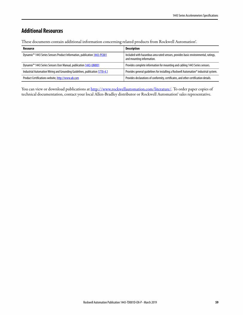
Additional Resources
These documents contain additional information concerning related products from Rockwell Automation®.
You can view or download publications at http://www.rockwellautomation.com/literature/. To order paper copies of technical documentation, contact your local Allen-Bradley distributor or Rockwell Automation® sales representative.
Resource Description
Dynamix™ 1443 Series Sensors Product Information, publication 1443-PC001 Included with hazardous area rated sensors, provides basic environmental, ratings, and mounting information.
Dynamix™ 1443 Series Sensors User Manual, publication 1443-UM001 Provides complete information for mounting and cabling 1443 Series sensors.
Industrial Automation Wiring and Grounding Guidelines, publication 1770-4.1 Provides general guidelines for installing a Rockwell Automation® industrial system.
Product Certifications website, http://www.ab.com Provides declarations of conformity, certificates, and other certification details.
Rockwell Automation Publication 1443-TD001D-EN-P - March 2019 59
Allen-Bradley, Dynamix, LISTEN. THINK. SOLVE., Rockwell Automation, and Rockwell Software are trademarks of Rockwell Automation, Inc.Trademarks not belonging to Rockwell Automation are property of their respective companies.
Publication 1443-TD001D-EN-P - March 2019
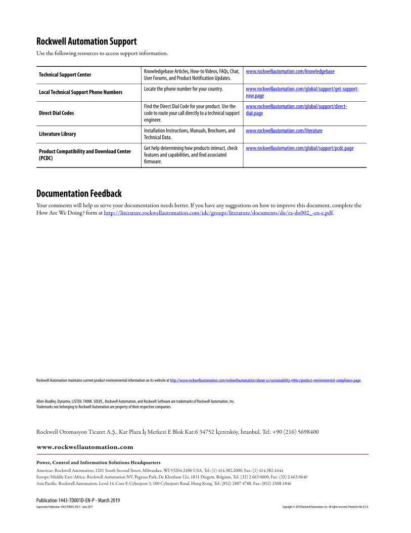
Rockwell Automation SupportUse the following resources to access support information.
Documentation FeedbackYour comments will help us serve your documentation needs better. If you have any suggestions on how to improve this document, complete the How Are We Doing? form at http://literature.rockwellautomation.com/idc/groups/literature/documents/du/ra-du002_-en-e.pdf.
Technical Support Center Knowledgebase Articles, How-to Videos, FAQs, Chat, User Forums, and Product Notification Updates.
www.rockwellautomation.com/knowledgebase
Local Technical Support Phone Numbers Locate the phone number for your country. www.rockwellautomation.com/global/support/get-support-now.page
Direct Dial CodesFind the Direct Dial Code for your product. Use the code to route your call directly to a technical support engineer.
www.rockwellautomation.com/global/support/direct-dial.page
Literature Library Installation Instructions, Manuals, Brochures, and Technical Data.
www.rockwellautomation.com/literature
Product Compatibility and Download Center (PCDC)
Get help determining how products interact, check features and capabilities, and find associated firmware.
www.rockwellautomation.com/global/support/pcdc.page
Rockwell Otomasyon Ticaret A.Ş., Kar Plaza İş Merkezi E Blok Kat:6 34752 İçerenköy, İstanbul, Tel: +90 (216) 5698400
Rockwell Automation maintains current product environmental information on its website at http://www.rockwellautomation.com/rockwellautomation/about-us/sustainability-ethics/product-environmental-compliance.page.
Supersedes Publication 1443-TD001C-EN-P - June 2017 Copyright © 2019 Rockwell Automation, Inc. All rights reserved. Printed in the U.S.A.