Embed Size (px)
Citation preview

Powerglide® Door Closer
1431 Series
Copyright © SARGENT Manufacturing Company 2005-2007, 2009-2015, All rights reserved. Reproduction in whole or in part without the express written permission of Sargent Manufacturing Company is prohibited.

9012
1:M
12/
03/1
5 Co
pyrig
ht ©
200
5-20
07, 2
009-
2015
, Sar
gent
Man
ufac
turin
g Co
mpa
ny, a
n AS
SA A
BLO
Y G
roup
com
pany
. All
right
s res
erve
d.
Repr
oduc
tion
in w
hole
or i
n pa
rt w
ithou
t the
exp
ress
writ
ten
perm
issi
on o
f Sar
gent
Man
ufac
turin
g Co
mpa
ny is
pro
hibi
ted.
1-800-727-5477 • www.sargentlock.com
The 1431 line of surface mounted door closers has been engineered to meet the demands of architects and building owners. The 1431 Series is a complete line of closers for interior and exterior doors with quality and flexibility to meet virtually every application.
On The Cover• SARGENT 1431 Door Closer with US26 plated O arm and metal cover
General Information . . . . . . . . . . . . . . . . . . . . . . . . . . . . . . . . . . . . . . . . . . . . . . . . . . . . . . . . . . . . . . . . . 1Features and Benefits . . . . . . . . . . . . . . . . . . . . . . . . . . . . . . . . . . . . . . . . . . . . . . . . . . . . . . . . . . . . . . . . 2Standard Applications. . . . . . . . . . . . . . . . . . . . . . . . . . . . . . . . . . . . . . . . . . . . . . . . . . . . . . . . . . . . . . . . 3Arms and Accessories for Standard Applications . . . . . . . . . . . . . . . . . . . . . . . . . . . . . . . . . . . . . . 4Top Jamb Applications . . . . . . . . . . . . . . . . . . . . . . . . . . . . . . . . . . . . . . . . . . . . . . . . . . . . . . . . . . . . . . . 5Arms for Top Jamb Applications . . . . . . . . . . . . . . . . . . . . . . . . . . . . . . . . . . . . . . . . . . . . . . . . . . . . . . 6Parallel Arm Applications. . . . . . . . . . . . . . . . . . . . . . . . . . . . . . . . . . . . . . . . . . . . . . . . . . . . . . . . . . . . . 7Heavy Duty Parallel Arms. . . . . . . . . . . . . . . . . . . . . . . . . . . . . . . . . . . . . . . . . . . . . . . . . . . . . . . . . . . . . 8Regular Duty Parallel Arms . . . . . . . . . . . . . . . . . . . . . . . . . . . . . . . . . . . . . . . . . . . . . . . . . . . . . . . . . . . 9Accessories for Parallel Applications . . . . . . . . . . . . . . . . . . . . . . . . . . . . . . . . . . . . . . . . . . . . . . . . . 10Track Type Applications . . . . . . . . . . . . . . . . . . . . . . . . . . . . . . . . . . . . . . . . . . . . . . . . . . . . . . . . . . . . . 11Suggested Architect’s Specifications,ADA Compliance and General Information . . . . . . . . . . . . . . . . . . . . . . . . . . . . . . . . . . . . . . . . . . 12Door Closer and Overhead Stop/HolderCompatibility Chart . . . . . . . . . . . . . . . . . . . . . . . . . . . . . . . . . . . . . . . . . . . . . . . . . . . . . . . . . . . . . . . . . 13How to Order . . . . . . . . . . . . . . . . . . . . . . . . . . . . . . . . . . . . . . . . . . . . . . . . . . . . . . . . . . . . . . . . . . . . . . . 14
Table of Contents1431 Series Powerglide®
Primary Closer Arm Identification Letters O Standard Arm H Hold Open Arm Z Deep Reveal Arm 2-1/8" to 5" ZA Extra Deep Reveal Arm 5-1/8" to 8" P Parallel Arm or Push Side S Arm with Positive Stop C Arm with Positive Cushioned Stop “C” is always accompanied by an “S” (Stop)
Note: Often more than one letter is used to describe one type of arm
Underwriters’ Laboratories ListingAll SARGENT Powerglide® Door Closers are listed by the Underwriters’ Laboratories, Inc. as follows: “For Self-Closing Doors Without Hold-Open Feature”Any retrofit or other field modification to a fire rated opening can potentially impact the fire rating of the opening, and Sargent Manufacturing Company makes no representations or warranties concerning what such impact may be in any specific situation. When retrofitting any portion of an existing fire rated opening, or specifying and installing a new fire-rated opening, please consult with a code specialist or local code official (Authority Having Jurisdiction) to ensure compliance with all applicable codes and ratings.

9012
1:M
12/
03/1
5 Co
pyrig
ht ©
200
5-20
07, 2
009-
2015
, Sar
gent
Man
ufac
turin
g Co
mpa
ny, a
n AS
SA A
BLO
Y G
roup
com
pany
. All
right
s res
erve
d.
Repr
oduc
tion
in w
hole
or i
n pa
rt w
ithou
t the
exp
ress
writ
ten
perm
issi
on o
f Sar
gent
Man
ufac
turin
g Co
mpa
ny is
pro
hibi
ted.
11-800-727-5477 • www.sargentlock.com
General Information1431 Series Powerglide®
Arm Leverage AdjustmentClosers using “O” arms have the provision to increase closing power by 15% by adjusting foot pivot
ANSI Standards
ARM TYPE ARM TYPE O CO2011 PF9 CO2101 P9 CO2021 P10 CO2021 H CO2051 PS/CPS CO2021 PH9 CO2061 CPSH/PSH CO2061
All are certified ANSI types including options PT4 A, B, D, E, F, G, H
How to Select the Proper Closer
Things to Consider 1. Size and Weight of Door The 1431 Door Closer is non-sized so that closing force can be adjusted in the field to accommodate various door sizes and weights.
2. Interior Application The standard application is the most efficient in terms of power and control.
3. Exterior Application The top jamb, parallel arm application should be used. Exterior doors require greater closing forces because of draft conditions. Always place the closers out of the weather.
4. Degree of Opening Proper arm and position on the door is most important to permit the door to open far enough to allow adequate traffic flow.
5. Function Closers are available with hold-open or positive stop arms.
6. Special Condition Consult factory when special hinges, overhead holders or other specialized hardware is used.
Closer Spring Adjustment (not shown)• Effects the entire cycle of the door
closer movement• Used to size closer for application requirements • Determines the amount of force with which the
door closes and the amount of force required to open the door
• Adjustable to compensate for door size and draft conditions
Delayed action valve (Optional)• Holds the door in the open position
momentarily • 20 second minimum hold open delay• The feature is available for all applications
and arms• Beneficial when moving carts or objects
thru door opening and ADA applications
Latching speed valve• Controls the speed of the door during the
final 8" of door swing• The force the door closes with is controlled
by the Closer spring• Note: This adjustment is critical for door latching
Closing speed valve• Controls how fast the door closes to
approximately 8" from the closed position
Door Closer Cycle
Opening Cycle
Backcheck valve• At approximately 70° of the open cycle,
the Backcheck Valve begins to slow the door’s motion
• Prevents the door from slamming into the door’s stop
• Valve is used to control the intensity of the Backcheck
• Note: A Positive stop is required, Backcheck cannot be used as a stop
L C
D
B

9012
1:M
12/
03/1
5 Co
pyrig
ht ©
200
5-20
07, 2
009-
2015
, Sar
gent
Man
ufac
turin
g Co
mpa
ny, a
n AS
SA A
BLO
Y G
roup
com
pany
. All
right
s res
erve
d.
Repr
oduc
tion
in w
hole
or i
n pa
rt w
ithou
t the
exp
ress
writ
ten
perm
issi
on o
f Sar
gent
Man
ufac
turin
g Co
mpa
ny is
pro
hibi
ted.
2 1-800-727-5477 • www.sargentlock.com
Features and Benefits1431 Series Powerglide®
The 1431 Series complies with ADA for reduced open forces
PRECISION KEY OPERATED VALVES
HIGH STRENGTH, WEAR RESISTANT ALUMINUM CASE
HEAT TREATEDALLOY STEEL
SPINDLE
SPRING POWER ADJUSTMENT
HIGH IMPACT COVER
O RING SEAL
L C
D
B
NEEDLEBEARINGS
O RING SEAL
B
D C L
Features• Exceeds 15 Million cycles• Certified ANSI/BHMA A156.4 Grade 1• UL 10C listed for positive pressure fire test• UL / cUL listed for use on fire rated doors• 25 year limited warranty• User friendly versatile mounting applications
permit standard, top jamb, parallel and track installations
• Self sticking templates supplied for most applications
• Adjustable spring power allows 1431 closers a size range of 1 through 6. They are adjusted to size 3 before leaving the factory
• One door closer body for all applications. All 1431 are non-handed
• Meets ADA requirements in all applications, except Push Side Track application (except track)
• High impact non-corrosive plastic covers with two machine screws standard, metal covers and lead lined are optional
• All weather fluid allows closer to operate effectively in extreme temperatures without readjustment
• 1-1/2" diameter piston for superior door control• Standard pressure relief valves for both
opening and closing cycles protect the door and frame from damage caused by abuse
• Retrofits existing SARGENT 1230/1231 Series Closer installations
Heavy Duty Construction• Heat treated full rack and pinion for high
Full Complement of Arm Types• Standard and parallel arms• Push and pull track arms• Heavy duty forged steel arms are finely
finished and interchangeable between SARGENT 281 and 1431, and 351 Series. The cold formed arms (RO/RP9) are unique to the 1431 series and not interchangeable with other SARGENT closers
strength and wear resistance• Heavy duty one piece high silicon content
aluminum alloy body provides corrosion resistance, superior strength and wear resistance
• 1/2" arm engagement over a 7/16 square spindle ensures a wear-resistant tight joint
Fasteners• Machine Screws and self tapping screws
provided for closer and arm• In addition, wood screws supplied when
installed on wood doors with through bolts
Valves• Separate brass low sensitivity control valves
offer ability to separately regulate door speed, latching, backcheck and optional delayed action
• All valves are captured to prevent accidental removal, adjustable with an 1/8" Allen wrench
• Adjustable backcheck protects the door and hardware from damage during the opening cycle
• Adjustable delayed action (optional) permits easy access for physically impaired individuals

9012
1:M
12/
03/1
5 Co
pyrig
ht ©
200
5-20
07, 2
009-
2015
, Sar
gent
Man
ufac
turin
g Co
mpa
ny, a
n AS
SA A
BLO
Y G
roup
com
pany
. All
right
s res
erve
d.
Repr
oduc
tion
in w
hole
or i
n pa
rt w
ithou
t the
exp
ress
writ
ten
perm
issi
on o
f Sar
gent
Man
ufac
turin
g Co
mpa
ny is
pro
hibi
ted.
31-800-727-5477 • www.sargentlock.com
Standard Applications1431 Series Powerglide®
1431 Standard Application Door Opening Range (Range based on Mounting Position)• O & RO Standard Arms: 120°–180°• H- Hold Open Arm: 90°–180°
1431 Standard Application for:• Interior Doors Opening In or Out• Exterior Doors Opening In
1431-O Standard Application
The standard application of the 1431 door closer is the most common and the most desirable. The closer mounts on the hinge (pull) side of door (except when the W Corner Bracket is used). Note: This application is not recommended on exterior doors swinging out, since the closer is not protected from weather. The cover projection normally limits the door opening to a maximum of 160°.
7/16" Maximum Reveal Depth
Wall Clearance Requirement
2-3/8" MIN SPACE (60mm)
Door in Closed Position
Cover Projection normally limits door opening to 160°
Door in Open Position
Ceiling
OLC - Low Ceiling Application Arm for Ceiling to Door Clearance of 1-1/4" – 1-1/2"Door Top Rail Requirement• 2-5/8" min. rail (116mm)• For Top Rails less than 3-3/4" with window
opening, the 1431-J Cover Plate is recommended
O ARM SHOWN
1-1/4"–1-1/2"
7-1/4" to 7-5/8"
3/8"
3-3/8"
2-1/4"
12"
3-3/4" - 7"
3-7/8"

9012
1:M
12/
03/1
5 Co
pyrig
ht ©
200
5-20
07, 2
009-
2015
, Sar
gent
Man
ufac
turin
g Co
mpa
ny, a
n AS
SA A
BLO
Y G
roup
com
pany
. All
right
s res
erve
d.
Repr
oduc
tion
in w
hole
or i
n pa
rt w
ithou
t the
exp
ress
writ
ten
perm
issi
on o
f Sar
gent
Man
ufac
turin
g Co
mpa
ny is
pro
hibi
ted.
4 1-800-727-5477 • www.sargentlock.com
Arms and Accessories forStandard Applications1431 Series Powerglide®
1431-W Corner Bracket • Fastens securely to both the head and jamb • Malleable iron, painted to match closer finish • Non-handed • Requires 1-1/4" (32mm) minimum wide stop • Order as 1431-W x finish
OLC - Standard Arm for Low Ceiling • Forged Steel Arm 11-1/4" (286mm) long • Non-handed • Must be used when the distance between the top of door to ceiling is less than 1-1/4" (32mm) • Permits 120° door opening with standard mounting For arm only, order as 25-OLC x finish Includes 63-2549 - Main arm and link assembly 63-2216 - Foot assembly 64-2407 - Screw pack
O8 - Mortise Foot Arm • Forged Steel Arm 11-1/4" (286mm) long • Non-handed • Permits 120° door opening • Commonly used with bull nose frames For arm only, order as 25-O8 x finish Includes: 63-2607 - Main arm and link assembly 63-2273 - Foot assembly 64-2407 & 63-2391 - Screw packs
H - Hold Open Arm • Forged Steel Arm 11-1/4" (286mm) long • Non-handed • Hand is changed
by inverting the foot assembly
• Friction type holder easily adjusted by a wrench • Permits 180° door opening • Holds open from 80° – 180° For arm only, order as 25-H x finish Includes: 63-2229 - Main arm and swivel assembly 61-2303 - Foot assembly 64-2407 - Screw pack
1431-J Cover Plate
• Can be used to improve appearance when narrow door rail permits closer to be viewed through glass panel. Specify finish.
H8 - Mortise Foot Hold Open Arm • Forged Steel Arm 11-1/4" (286mm) long • Handed same as door • Friction type holder easily adjusted by a wrench • Holds open from 80° – 180° For arm only, order 25 R-H8 x finish for right hand or 25 L-H8 x finish for left hand Includes: 63-2229 - Main arm & link assembly 63-2289 - Left hand foot assembly 63-2290 - Right hand foot assembly 63-2290RH - Foot assembly 64-2407 & 63-2391- Screw packs
O - Standard Arm • Forged Steel Arm 11-1/4" (286mm) long • Non-handed • Permits 120° door opening with standard mounting • Permits 180° door opening with alternate mounting or corner bracket For arm only, order as 25-O x finish Includes: 63-2607 - Main arm and link assembly 63-2216 - Foot assembly 64-2407 - Screw pack
UO/RUO Packages • Universal arm package provides brackets and arms to install closer in standard top jamb or parallel applications
Screw packs64-2407 & 63-2391
125-P9
UH Package • Universal hold open arm package provides brackets and arms to install closer in top jamb, standard or parallel applications
Screw packs64-2407 & 63-2391
125-PH9
RO Regular Arm • Cold Formed Steel
Arm 11-1/4 (286mm) long
• For reveal depths up to 2" (51mm)
• Arm is not handed • Permits 180° door
opening For arm only, order as 25-RO x finish Includes: 63-3396 -Main arm and link assembly
63-2216 -Foot assembly 64-2407 Screw pack

9012
1:M
12/
03/1
5 Co
pyrig
ht ©
200
5-20
07, 2
009-
2015
, Sar
gent
Man
ufac
turin
g Co
mpa
ny, a
n AS
SA A
BLO
Y G
roup
com
pany
. All
right
s res
erve
d.
Repr
oduc
tion
in w
hole
or i
n pa
rt w
ithou
t the
exp
ress
writ
ten
perm
issi
on o
f Sar
gent
Man
ufac
turin
g Co
mpa
ny is
pro
hibi
ted.
51-800-727-5477 • www.sargentlock.com
Top Jamb Applications1431 Series Powerglide®
Top Jamb Application for Low Ceilings using 1431-B Mounting Plate
• Required for low ceiling condition and narrow face frames
• Available w/powder coat or plated finish to match cover
• Non-handed • Plate mounting screws included • Order as 1431-B x finish
Minimum Door Top Rail Required to Mount Closer Foot• 1-7/8" (48mm) minimum• Rail height required depends on type and
make of auxiliary holder if used
Adjustable Closing Force• Interior doors to 5'0" wide• Exterior doors to 4'0" wide• Shipped factory preset for 3'0" door• Factory pre-sized upon request
1431-O Top Jamb Mounting Position
Minimum Frame Face Required• 1-3/4" (44mm) for both single and double rabbeted frames
Top Jamb applications – The 1431 closer is mounted on the frame face above the door. The foot is mounted on the push side of door. This application is for use on exterior doors opening out to protect the closer from the weather.
OZ ARM SHOWN
1431-O Typical Reveal Top Jamb ApplicationsFor reveals up to 2" (51mm) maximum• O or RO Arms - Max. Door Opening: 180°• H Arm - Hold Open Range: 80° – 180°
1431-OZ Deep Reveal Top Jamb ApplicationsFor reveals from 2-1/8" (54mm) to 5" (127mm)• OZ Arm - Max. Door Opening: 140°• HZ Arm - Hold Open Range: 80° – 140°
1431-OZA Extra Deep Reveal Top Jamb ApplicationsFor reveals from 5-1/8" (130mm) to 8" (230mm)• OZA Arm - Max. Door Opening: 140°• HZA Arm - Hold Open Range: 80° – 130°
Reveal Depth
Top JambApplication
Frame
12"
3-3/8"
1-1/2" -9"
2-7/8"
1-7/16" (37mm) min., Ceiling/Frame Face
1431-Bmounting plate
9-1/8"
11-1/8" (232mm)(283mm)
9012
1:M
12/
03/1
5 Co
pyrig
ht ©
200
5-20
07, 2
009-
2015
, Sar
gent
Man
ufac
turin
g Co
mpa
ny, a
n AS
SA A
BLO
Y G
roup
com
pany
. All
right
s res
erve
d.
Repr
oduc
tion
in w
hole
or i
n pa
rt w
ithou
t the
exp
ress
writ
ten
perm
issi
on o
f Sar
gent
Man
ufac
turin
g Co
mpa
ny is
pro
hibi
ted.
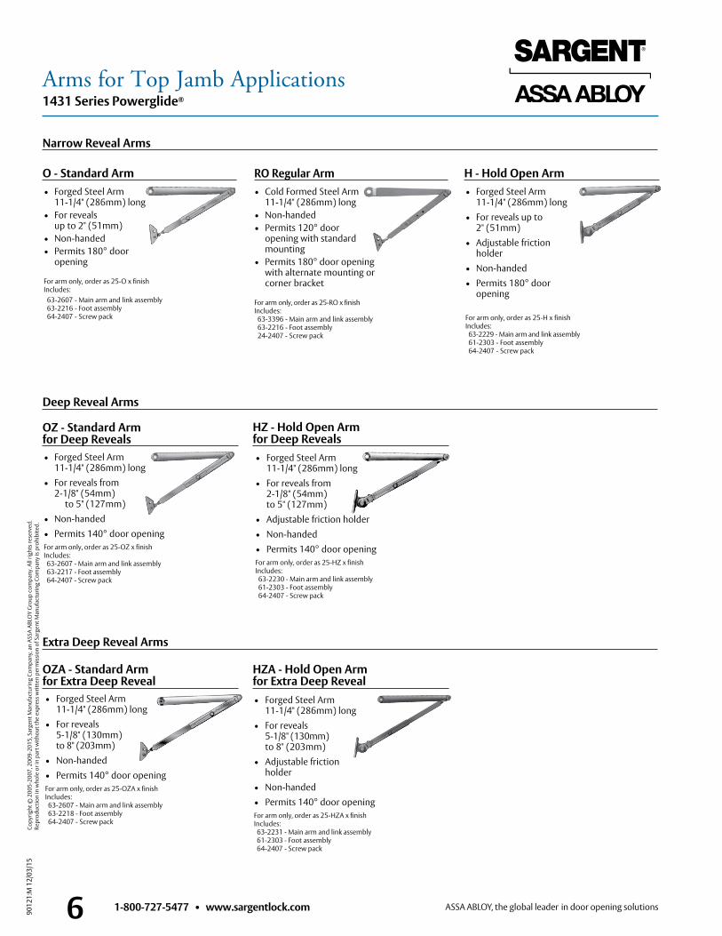
• Forged Steel Arm 11-1/4" (286mm) long• For reveals up to
2" (51mm)• Adjustable friction
holder• Non-handed • Permits 180° door
opening For arm only, order as 25-H x finish Includes: 63-2229 - Main arm and link assembly
61-2303 - Foot assembly 64-2407 - Screw pack
6 1-800-727-5477 • www.sargentlock.com
Arms for Top Jamb Applications1431 Series Powerglide®
• Forged Steel Arm 11-1/4" (286mm) long
• For reveals 5-1/8" (130mm) to 8" (203mm)• Adjustable friction
holder • Non-handed• Permits 140° door openingFor arm only, order as 25-HZA x finish Includes: 63-2231 - Main arm and link assembly
61-2303 - Foot assembly 64-2407 - Screw pack
HZA - Hold Open Arm for Extra Deep Reveal
H - Hold Open Arm
• Forged Steel Arm 11-1/4" (286mm) long• For reveals from 2-1/8" (54mm) to 5" (127mm)• Adjustable friction holder• Non-handed• Permits 140° door openingFor arm only, order as 25-HZ x finish Includes: 63-2230 - Main arm and link assembly
61-2303 - Foot assembly 64-2407 - Screw pack
HZ - Hold Open Arm for Deep Reveals
• Forged Steel Arm 11-1/4" (286mm) long• For reveals from
2-1/8" (54mm) to 5" (127mm)
• Non-handed• Permits 140° door openingFor arm only, order as 25-OZ x finish Includes: 63-2607 - Main arm and link assembly
63-2217 - Foot assembly 64-2407 - Screw pack
OZ - Standard Arm for Deep Reveals
• Forged Steel Arm 11-1/4" (286mm) long• For reveals 5-1/8" (130mm) to 8" (203mm)• Non-handed• Permits 140° door openingFor arm only, order as 25-OZA x finish Includes: 63-2607 - Main arm and link assembly
63-2218 - Foot assembly 64-2407 - Screw pack
OZA - Standard Arm for Extra Deep Reveal
• Forged Steel Arm 11-1/4" (286mm) long
• For reveals up to 2" (51mm)
• Non-handed• Permits 180° door
opening For arm only, order as 25-O x finish Includes: 63-2607 - Main arm and link assembly
63-2216 - Foot assembly 64-2407 - Screw pack
O - Standard Arm RO Regular Arm • Cold Formed Steel Arm
11-1/4" (286mm) long• Non-handed• Permits 120° door
opening with standard mounting
• Permits 180° door opening with alternate mounting or corner bracket
For arm only, order as 25-RO x finish Includes: 63-3396 - Main arm and link assembly
63-2216 - Foot assembly 24-2407 - Screw pack
Narrow Reveal Arms
Deep Reveal Arms
Extra Deep Reveal Arms

9012
1:M
12/
03/1
5 Co
pyrig
ht ©
200
5-20
07, 2
009-
2015
, Sar
gent
Man
ufac
turin
g Co
mpa
ny, a
n AS
SA A
BLO
Y G
roup
com
pany
. All
right
s res
erve
d.
Repr
oduc
tion
in w
hole
or i
n pa
rt w
ithou
t the
exp
ress
writ
ten
perm
issi
on o
f Sar
gent
Man
ufac
turin
g Co
mpa
ny is
pro
hibi
ted.
71-800-727-5477 • www.sargentlock.com
Parallel Arm Applications1431 Series Powerglide®
P9 ARM SHOWN
Standard Mounting Position• 120° Maximum door opening • Holding range of friction
hold open arms: 75° – 110°
Alternate Mounting Position
• Maximum door opening: 180°• Holding range of friction
hold open arms: 85° – 170°
Non hold-open arms• Two mounting positions for 120° and 180°
maximum door openings
Stop arms• 6 mounting positions allow stop from 85° – 110°
Available Arms for institutional installations:• Regular Duty Parallel Arms• Offset Bracket Arms for use with
Auxiliary Holders & Stops• Parallel flush frame arms • Flush frame arms for use with Auxiliary Holders & Stops• Flush frame, friction hold open arms• Friction hold open arms• Use friction hold open arms for doors subject
to moderate hold open use
For use in high traffic and abusive environments• Friction and positive hold open arms
available• Use friction hold open arms for doors subject
to moderate hold open use• Use positive stop hold open arms for doors
subject to frequent hold open use• Dead stop and compression stop arms
available
1431-P9 Regular Parallel Arm Application
Parallel Arm Applications – The 1431 closer is mounted on the push side of the door with the arm under the frame parallel to the face of the door. This application is well suited for narrow face frames and deep reveal applications. The closer arm does not project into the room, and the door can be swung open much farther than in Top Jamb Application.
P9 Parallel Arm
1/4" - 2-15/16"
1" MIN(25mm)
5-9/16"
3 3/8"
2 1/4"12"
Positive stop hold open arms• 6 mountings provide hold open positioning
from 85° – 110°
Friction hold open arm• Two mountings provide adjustable hold open
positions from 75° – 180°
Heavy Duty Parallel Arms
Regular Duty Parallel Arms

9012
1:M
12/
03/1
5 Co
pyrig
ht ©
200
5-20
07, 2
009-
2015
, Sar
gent
Man
ufac
turin
g Co
mpa
ny, a
n AS
SA A
BLO
Y G
roup
com
pany
. All
right
s res
erve
d.
Repr
oduc
tion
in w
hole
or i
n pa
rt w
ithou
t the
exp
ress
writ
ten
perm
issi
on o
f Sar
gent
Man
ufac
turin
g Co
mpa
ny is
pro
hibi
ted.
8 1-800-727-5477 • www.sargentlock.com
Heavy Duty Parallel Arms1431 Series Powerglide®
PS - Heavy Duty Parallel Arm with Positive Stop
• Forged Steel Arm 11-1/4" (286mm) long • Handed arm is field-reversible • Provides built in stop from 85° – 110° • Permits 110° opening maximum • Easily installed • Permits 85° – 110° door opening For arm only, order as 25-PS x finish Includes: 63-0641 - Main arm
63-3837 - Arm and bracket assembly 64-2407 & 63-2392, 63-2396 - Screw packs
P10 - Heavy Duty Parallel Arm
• Forged Steel Arm 11-1/4" (286mm) long • Non-handed • Easily installed • Permits 120° opening at standard mounting • Permits 180° opening at alternate mounting For arm only, order as 25-P10 x finish Includes: 63-0641 - Main arm
63-3727 - Arm and bracket assembly 64-2407 & 63-2392 - Screw packs
• Forged Steel Arm 11-1/4" (286mm) long • Provides built in compression stop from 85° – 105° • Permits 105° opening maximum • Easily installed • Handed arm is field-reversible • Dead stop within 3° For arm only, order as 25-CPS x finish Includes: 63-0641 - Main arm
63-3830 - Arm and bracket assembly 63-0516 - Bumper holder 63-3493 - Bumper 64-2407 & 63-2398 - Screw packs
CPS - Heavy Duty Parallel Arm with Compression Stop
• Forged Steel Arm 11-1/4" (286mm) long • Handed arm is field-reversible • Provides built in compression stop
and holder mechanism from 85° – 105° • Easily installed/adjusted • Permits 105° opening maximum • Dead stop within 3° For arm only, order as 25-CPSH x finish Includes: 63-0641 - Main arm 63-3836 - Arm and bracket assembly 63-0516 - Bumper holder 63-3493 - Bumper 64-2407 & 63-3487 - Screw packs
CPSH - Heavy Duty Hold Open Parallel Arm with Compression Stop
The PSH and CPSH arms project 2 3/4" below the head stop
PSH - Heavy Duty Parallel Hold Open Arm with positive Stop
• Provides holder and stop features • Handed arm is field-reversible • Easily installed/adjusted • Permits 85° – 110° door opening For arm only, order as 25-PSH x finish Includes: 63-0641 - Main arm
63-3833 - Arm and bracket assembly 64-2407 & 63-2392, 63-2396 - Screw packs
• Equipped with adjustable friction holder • Adjustable hold open from 75° – 180° • Forged steel arm 11-1/4" (286mm) long • Handed same as door • Use friction hold open arms for doors subject to moderate hold open use For arm only, order as 25-PH10 x finish Includes: 63-0641 - Main arm
63-3839 - Left hand arm and bracket assembly 63-3840 - Right hand arm and bracket assembly 64-2407 & 63-2392 - Screw packs
PH10 - Heavy Duty Friction Hold Open Parallel Arm
Positive Stop Hold Open Arms (PSH & CPSH ARMS) • Use on doors subject to repetitive hold
open use • 6 hold open angle installation • Hold open function may be disengaged • Hold open tension is easily adjustable
9012
1:M
12/
03/1
5 Co
pyrig
ht ©
200
5-20
07, 2
009-
2015
, Sar
gent
Man
ufac
turin
g Co
mpa
ny, a
n AS
SA A
BLO
Y G
roup
com
pany
. All
right
s res
erve
d.
Repr
oduc
tion
in w
hole
or i
n pa
rt w
ithou
t the
exp
ress
writ
ten
perm
issi
on o
f Sar
gent
Man
ufac
turin
g Co
mpa
ny is
pro
hibi
ted.
91-800-727-5477 • www.sargentlock.com
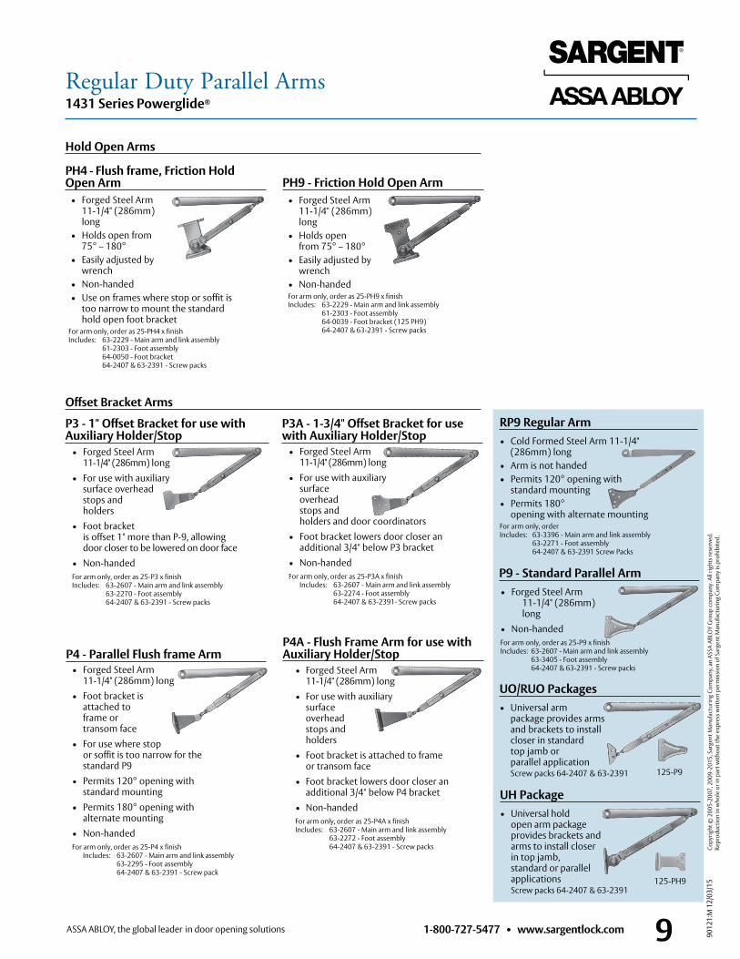
Regular Duty Parallel Arms1431 Series Powerglide®
• Forged Steel Arm 11-1/4" (286mm) long • Holds open from 75° – 180° • Easily adjusted by wrench • Non-handed For arm only, order as 25-PH9 x finish Includes: 63-2229 - Main arm and link assembly
61-2303 - Foot assembly 64-0039 - Foot bracket (125 PH9) 64-2407 & 63-2391 - Screw packs
PH9 - Friction Hold Open Arm
P4 - Parallel Flush frame Arm • Forged Steel Arm 11-1/4" (286mm) long • Foot bracket is attached to frame or transom face • For use where stop
or soffit is too narrow for the standard P9
• Permits 120° opening with standard mounting • Permits 180° opening with alternate mounting • Non-handed For arm only, order as 25-P4 x finish Includes: 63-2607 - Main arm and link assembly
63-2295 - Foot assembly 64-2407 & 63-2391 - Screw pack
• Forged Steel Arm 11-1/4" (286mm) long • For use with auxiliary surface overhead stops and holders • Foot bracket is offset 1" more than P-9, allowing
door closer to be lowered on door face • Non-handed For arm only, order as 25-P3 x finish Includes: 63-2607 - Main arm and link assembly
63-2270 - Foot assembly 64-2407 & 63-2391 - Screw packs
P3 - 1" Offset Bracket for use with Auxiliary Holder/Stop
• Forged Steel Arm 11-1/4" (286mm) long • For use with auxiliary surface overhead stops and holders and door coordinators • Foot bracket lowers door closer an
additional 3/4" below P3 bracket • Non-handed For arm only, order as 25-P3A x finish Includes: 63-2607 - Main arm and link assembly
63-2274 - Foot assembly 64-2407 & 63-2391- Screw packs
P3A - 1-3/4" Offset Bracket for use with Auxiliary Holder/Stop
• Forged Steel Arm 11-1/4" (286mm) long • For use with auxiliary surface overhead stops and holders • Foot bracket is attached to frame or transom face • Foot bracket lowers door closer an
additional 3/4" below P4 bracket • Non-handed For arm only, order as 25-P4A x finish Includes: 63-2607 - Main arm and link assembly 63-2272 - Foot assembly 64-2407 & 63-2391 - Screw packs
P4A - Flush Frame Arm for use with Auxiliary Holder/Stop
• Forged Steel Arm 11-1/4" (286mm) long • Holds open from 75° – 180° • Easily adjusted by wrench • Non-handed • Use on frames where stop or soffit is
too narrow to mount the standard hold open foot bracket
For arm only, order as 25-PH4 x finish Includes: 63-2229 - Main arm and link assembly
61-2303 - Foot assembly 64-0050 - Foot bracket 64-2407 & 63-2391 - Screw packs
PH4 - Flush frame, Friction Hold Open Arm
• Forged Steel Arm 11-1/4" (286mm) long• Non-handed For arm only, order as 25-P9 x finish Includes: 63-2607 - Main arm and link assembly
63-3405 - Foot assembly 64-2407 & 63-2391 - Screw packs
P9 - Standard Parallel Arm
UO/RUO Packages • Universal arm package provides arms and brackets to install closer in standard top jamb or parallel application Screw packs 64-2407 & 63-2391 125-P9
UH Package• Universal hold
open arm package provides brackets and arms to install closer in top jamb, standard or parallel applications Screw packs 64-2407 & 63-2391
125-PH9
RP9 Regular Arm• Cold Formed Steel Arm 11-1/4"
(286mm) long• Arm is not handed• Permits 120° opening with
standard mounting• Permits 180°
opening with alternate mountingFor arm only, order Includes: 63-3396 - Main arm and link assembly
63-2271 - Foot assembly 64-2407 & 63-2391 Screw Packs
Hold Open Arms
Offset Bracket Arms

9012
1:M
12/
03/1
5 Co
pyrig
ht ©
200
5-20
07, 2
009-
2015
, Sar
gent
Man
ufac
turin
g Co
mpa
ny, a
n AS
SA A
BLO
Y G
roup
com
pany
. All
right
s res
erve
d.
Repr
oduc
tion
in w
hole
or i
n pa
rt w
ithou
t the
exp
ress
writ
ten
perm
issi
on o
f Sar
gent
Man
ufac
turin
g Co
mpa
ny is
pro
hibi
ted.
10 1-800-727-5477 • www.sargentlock.com
Accessories for Parallel Applications1431 Series Powerglide®
581-1 Blade Stop Spacer Kit • Converts O or P9 arm to P4A Arm
125-P4A Arm Conversion Unit • Converts O or P9 Arm to P4A Arm
125-P4 Conversion Unit
• Required for parallel arm applications with top rails less then 5-3/4" • Requires 3" (76mm) minimum top rail • Available with powder coat or plated finish to match closer • Non-handed – Plate mounting screws included • Order as 1431-D x finish
• Converts O or P9 arm to P3 Parallel Arm • Converts O or P9 Arm to P3A Parallel Arm
• Converts standard hold open (H) arm to PH9 Parallel Hold Open Arm
1431 Drop Plate
• Can be used to improve appearance when narrow door rail permits closer to be viewed through glass panel
1431 J Cover Plate
125-PH9 Parallel Arm Foot125-P3A Arm Conversion Unit125-P3 Arm Conversion Unit
• For frames with 1/2" blade stops • For use with P10, PH10, PS, PSH, CPS and CPSH arms • 125-V bracket included • Packed with 1-1/4" long screws • Use P/N 64-0157 to order blade stop only
581-2 Blade Stop Spacer Kit • 1/2" x 5/8" • Included standard with PS, PSH, PH10,
P-10 CPS and CPSH arm for use with rabbited frames
Spacer 63-0191125-V/125-VF Brackets
125-V 125-VF • For use with all heavy duty parallel arms • Use 125-V for narrow stop and frame conditions • Use 125-VF for flush door and frame conditions
585 Retrofit Kits The 585 kit allows easy upgrade from existing 1230/1231 Series to the 1431 Series. Kit includes closer, full cover, and fasteners.585-2 Replaces 1230/1231 585-4 Replaces 1230 DA/1231 DA
• For frames with 1/2" blade stops • For use with P9, PH9 and PF9 arms only • Packed with 1-1/4" long screws
1431-DDrop Plate
9-1/8"
11-1/8"
Heavy Duty Parallel Accessories
Regular Duty Parallel Accessories
Miscellaneous Accessories
9012
1:M
12/
03/1
5 Co
pyrig
ht ©
200
5-20
07, 2
009-
2015
, Sar
gent
Man
ufac
turin
g Co
mpa
ny, a
n AS
SA A
BLO
Y G
roup
com
pany
. All
right
s res
erve
d.
Repr
oduc
tion
in w
hole
or i
n pa
rt w
ithou
t the
exp
ress
writ
ten
perm
issi
on o
f Sar
gent
Man
ufac
turin
g Co
mpa
ny is
pro
hibi
ted.
111-800-727-5477 • www.sargentlock.com
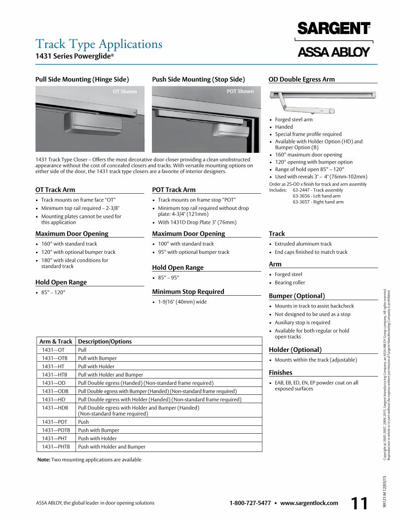
Track Type Applications1431 Series Powerglide®
• Forged steel arm• Handed• Special frame profile required• Available with Holder Option (HD) and
Bumper Option (B)• 160° maximum door opening• 120° opening with bumper option• Range of hold open 85° – 120°• Used with reveals 3" – 4" (76mm-102mm)Order as 25-OD x finish for track and arm assembly Includes: 63-2447 - Track assembly 63-3656 - Left hand arm 63-3657 - Right hand arm
OD Double Egress ArmPull Side Mounting (Hinge Side) Push Side Mounting (Stop Side)
1431 Track Type Closer – Offers the most decorative door closer providing a clean unobstructed appearance without the cost of concealed closers and tracks. With versatile mounting options on either side of the door, the 1431 track type closers are a favorite of interior designers.
Maximum Door Opening• 160° with standard track• 120° with optional bumper track• 180° with ideal conditions for standard track
Minimum Stop Required• 1-9/16" (40mm) wide
Maximum Door Opening• 100° with standard track• 95° with optional bumper track
Hold Open Range• 85° – 95°
OT Track Arm• Track mounts on frame face “OT”• Minimum top rail required – 2-3/8" • Mounting plates cannot be used for this application
POT Track Arm• Track mounts on frame stop “POT”• Minimum top rail required without drop plate: 4-3/4" (121mm) • With 1431D Drop Plate 3" (76mm)
Hold Open Range• 85° – 120°
Finishes • EAB, EB, ED, EN, EP powder coat on all
exposed surfaces
Arm• Forged steel• Bearing roller
Bumper (Optional)• Mounts in track to assist backcheck • Not designed to be used as a stop • Auxiliary stop is required• Available for both regular or hold open tracks
Holder (Optional)• Mounts within the track (adjustable)
Track• Extruded aluminum track• End caps finished to match track
Note: Two mounting applications are available
Arm & Track Description/Options 1431—OT Pull 1431—OTB Pull with Bumper 1431—HT Pull with Holder 1431—HTB Pull with Holder and Bumper 1431—OD Pull Double egress (Handed) (Non-standard frame required) 1431—ODB Pull Double egress with Bumper (Handed) (Non-standard frame required) 1431—HD Pull Double egress with Holder (Handed) (Non-standard frame required) 1431—HDB Pull Double egress with Holder and Bumper (Handed) (Non-standard frame required) 1431—POT Push 1431—POTB Push with Bumper 1431—PHT Push with Holder 1431—PHTB Push with Holder and Bumper
OT Shown POT Shown

9012
1:M
12/
03/1
5 Co
pyrig
ht ©
200
5-20
07, 2
009-
2015
, Sar
gent
Man
ufac
turin
g Co
mpa
ny, a
n AS
SA A
BLO
Y G
roup
com
pany
. All
right
s res
erve
d.
Repr
oduc
tion
in w
hole
or i
n pa
rt w
ithou
t the
exp
ress
writ
ten
perm
issi
on o
f Sar
gent
Man
ufac
turin
g Co
mpa
ny is
pro
hibi
ted.
12 1-800-727-5477 • www.sargentlock.com
Suggested Architect’s Specifications,ADA Compliance and General Information1431 Series Powerglide®
Special ConditionsThe SARGENT Website (www.sargentlock.com) contains templates for all standard applications of SARGENT Door Closers with SARGENT overhead door holders. To insure a satisfactory installation for other holders, it is recommended that complete details be submitted as follows:
• Type, size and make of holder
• Holding position (maximum door opening)
• Submit holder template being used
• Closer application being used
• Size and type of hinge
In the case of an unusual door, frame and/or hinge conditions where regular products do not meet requirements, submit drawings and complete details specifying the degree of door openings required, the type and size of hinge and the max. door opening angle.
Through-bolting and Mortise Nuts• When through-bolting is ordered, factory
will furnish mortise nuts for use with the machine screws furnished with the closer
• Nuts are sized to accommodate 1-3/4" (44mm) standard or 1-3/8" (35mm)
thick doors when specified on order
• For 2-1/4" (57mm) thick doors, longer through-bolts will be furnished with mortise nuts
• Through-bolting for 2-1/4" (57mm) thick hollow metal doors require bridge type reinforcement to prevent collapse of top rail when through-bolts are tightened
Special Rust Inhibitor Process (SRI)The aluminum body of the 1431 provides a high level of corrosion protection in many environments. An additional process (SRI) is available to provide the arms an extra layer of protection for extreme corrosive environments. Specify SRI as an option when ordering.
1. All closers for both interior and exterior doors shall be the product of one manufacturer and be matched in style.
2. Surface closers shall be adjustable to provide sizes 1 through 6 and comply with ADA. 3. Full rack and pinion construction. 4. Closing speed, latching speed and backcheck shall be controlled by key
operated valves. 5. Delayed action feature shall be available and controlled by a separate valve.
Delayed action shall be available in addition to, not in lieu of, backcheck. 6. The one piece closer body shall be manufactured of high-performance cast
aluminum silicon alloy. 7. An increase of 15% in closing power shall be provided by means of adjustment
of the arm leverage at the foot connection. (Standard Arm) 8. All arms shall be finely finished with heavy duty forged steel main arm. 9. Two mounting positions of the closer shall meet all requirements. Standard
mountings shall provide 120° door opening and alternate mounting 180° door opening. 10. All closers shall be suitable for standard, corner bracket, top jamb, parallel arm and track
type applications when provided with proper brackets and arms. 11. Closer covers shall be of high impact plastic material of flame retardant grade, secured
by machine screws. 12. Projection of closer body from door shall not exceed 2-1/4" (57mm) with standard cover. 13. Closers shall be non-handed to meet a variety of door conditions and design requirements. 14. The spindle shaft shall be sealed hydraulically with an “O” ring. 15. Specify desired options such as: Metal Cover, Security Package, (SRI) Special Rust Inhibitor
Process, (TB) Through-bolting, (DA) Delayed Action and Architectural Plated Finishes. 16. Closers should have two pressure relief valves (opening and closing cycles). 17. All closers to have a 25 year limited warranty. 18. Closers should comply with UL-10C and UBC 7-2 (1997) Positive Pressure Fire Test.
Architectural Specifications
1431 Designed to Aid the Physically Challenged The 1431 door closer is designed to meet the opening force requirements established by the American with Disabilities Act (ADA) limiting the opening force to 5 pounds for interior doors and 8 pounds for exterior doors. The closer should be installed using the alternate mounting given on the templates when used on interior doors.
CAUTION: The entire opening should be reviewed when ADA requirements must be met. Heavy doors add to the opening force while requiring more force to close. Poor quality hinges will add frictional resistance to the door and require more force to open and close. HVAC imbalances can cause a wind load that may also add to the opening forces. In these applications, a manual door closer may be unable to reliably close and latch a door when adjusted to ADA requirements. In these situations, a SARGENT low energy door operator should be used.
General Information
9012
1:M
12/
03/1
5 Co
pyrig
ht ©
200
5-20
07, 2
009-
2015
, Sar
gent
Man
ufac
turin
g Co
mpa
ny, a
n AS
SA A
BLO
Y G
roup
com
pany
. All
right
s res
erve
d.
Repr
oduc
tion
in w
hole
or i
n pa
rt w
ithou
t the
exp
ress
writ
ten
perm
issi
on o
f Sar
gent
Man
ufac
turin
g Co
mpa
ny is
pro
hibi
ted.
131-800-727-5477 • www.sargentlock.com
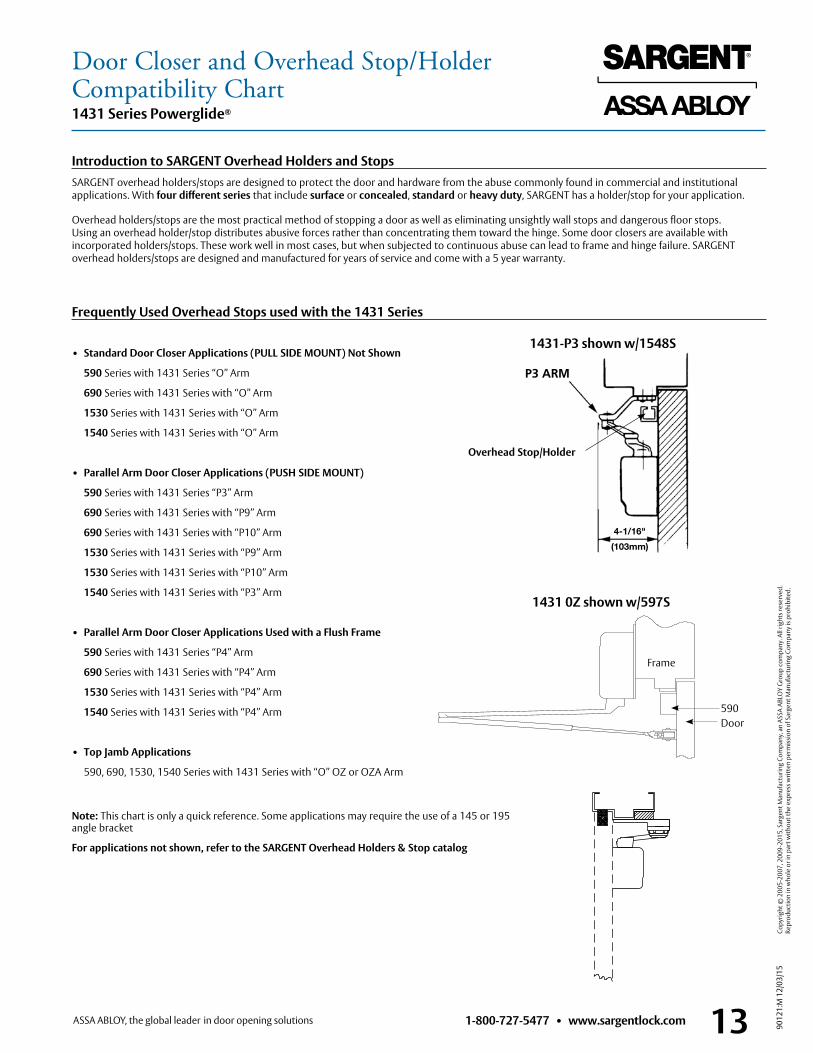
Door Closer and Overhead Stop/HolderCompatibility Chart1431 Series Powerglide®
Overhead Stop/Holder
Introduction to SARGENT Overhead Holders and StopsSARGENT overhead holders/stops are designed to protect the door and hardware from the abuse commonly found in commercial and institutional applications. With four different series that include surface or concealed, standard or heavy duty, SARGENT has a holder/stop for your application.
Overhead holders/stops are the most practical method of stopping a door as well as eliminating unsightly wall stops and dangerous floor stops. Using an overhead holder/stop distributes abusive forces rather than concentrating them toward the hinge. Some door closers are available with incorporated holders/stops. These work well in most cases, but when subjected to continuous abuse can lead to frame and hinge failure. SARGENT overhead holders/stops are designed and manufactured for years of service and come with a 5 year warranty.
• Standard Door Closer Applications (PULL SIDE MOUNT) Not Shown
590 Series with 1431 Series “O” Arm
690 Series with 1431 Series with “O” Arm
1530 Series with 1431 Series with “O” Arm
1540 Series with 1431 Series with “O” Arm
• Parallel Arm Door Closer Applications (PUSH SIDE MOUNT)
590 Series with 1431 Series “P3” Arm
690 Series with 1431 Series with “P9” Arm
690 Series with 1431 Series with “P10” Arm
1530 Series with 1431 Series with “P9” Arm
1530 Series with 1431 Series with “P10” Arm
1540 Series with 1431 Series with “P3” Arm
• Parallel Arm Door Closer Applications Used with a Flush Frame
590 Series with 1431 Series “P4” Arm
690 Series with 1431 Series with “P4” Arm
1530 Series with 1431 Series with “P4” Arm
1540 Series with 1431 Series with “P4” Arm
• Top Jamb Applications
590, 690, 1530, 1540 Series with 1431 Series with “O” OZ or OZA Arm
Note: This chart is only a quick reference. Some applications may require the use of a 145 or 195 angle bracket
For applications not shown, refer to the SARGENT Overhead Holders & Stop catalog
1431-P3 shown w/1548S
1431 0Z shown w/597S
Frame
Door590
Frequently Used Overhead Stops used with the 1431 Series

9012
1:M
12/
03/1
5 Co
pyrig
ht ©
200
5-20
07, 2
009-
2015
, Sar
gent
Man
ufac
turin
g Co
mpa
ny, a
n AS
SA A
BLO
Y G
roup
com
pany
. All
right
s res
erve
d.
Repr
oduc
tion
in w
hole
or i
n pa
rt w
ithou
t the
exp
ress
writ
ten
perm
issi
on o
f Sar
gent
Man
ufac
turin
g Co
mpa
ny is
pro
hibi
ted.
14 1-800-727-5477 • www.sargentlock.com
How to Order1431 Series Powerglide®
Series Number per Carton Approx. wt per CartonPackingAll closer assemblies are packaged 4 per carton. On request, door closers will be packed 2 per carton.
How To Order Accessories ExampleArm only Specify 25-, arm required and finish 25-PSH ENBody only Specify CB-1431 CB-1431 (Option DA- available) Arm conversion Units Specify unit and finish 125-P9 EBCover Only (Standard) 1431-C x finish 1431-C x ENCover Only (Metal) 1431-CMC x finish and hand & 1431-CMC x arm type 26D x LH X P-10Accessories Specify accessory and finish 1431-D EB See applicable catalog sectionWhen complete closer assembly is ordered with an accessory, order accessory as a separate item
1431 4-Standard (2 upon request) 19 lbs. per 4
Special Rust Inhibitor Process (SRI)Additional process available for bracket and arms provides an extra layer of protection for extreme corrosive environments. Available with powder coated finishes only, specify SRI- as an option when ordering.
How To OrderCPC-DA 1431 P4H 26 LH
Options Series Closer Arm Finish Hand
31-36-74-CPCDA-MC-SG-SRI-TB-
1431 Standard Page 4
Top Jamb Page 6
Parallel Pages 8 & 9
Track TypePage 11
EBEDENEP
EAB03*04*09*10*
10B*10BE10BL*
14* 15*
20D*26*
26D*
LHRH
* These finishes are automatically provided with a metal cover
Options AvailableSpecify Detailed Description
31- For doors 1-7/8" – 2-1/4" thick, specify door thickness, doors over 2-1/4" thick contact factory
36- Security Torx Screws supplied for all exposed fasteners
74- Lead lined cover
CPC- Clear Powder Coat (available on 26 & 26D)
DA- Delayed Action
MC- Handed Metal Cover
SRI- Special Rust Inhibitor finish for powder coated finishes only (arm)
TB- Through Bolt (1-3/4" Std) For others, specify 31-TB- & door thickness
Note:• The MC- option is used when a metal cover is desired on a powder
coated finish• When MC- is added to a plated finish, the MC- option indicates that only the
cover is to be plated, the arms will be powder coated to match• Do not specify the MC option if both the cover and arms are to be plated
Finishes Finishes ANSI/BHMA Description
EB 695 Bronze powder coated to match finish 10B EN 689 Aluminum powder coated ED 693 Black powder coated to match finish 20D
EAB 696 Brass powder coated EP 691 Bronze powder coated to match finish 10 03 605 Bright brass, clear coated 04 606 Satin brass, clear coated 09 611 Bright bronze, clear coated 10 612 Satin bronze, clear coated
10B 613 Dark oxidized satin bronze, oil rubbed10BE 613E Dark oxidized satin bronze - equivalent10BL 614 Oxidized satin, bronze, clear coated
14 618 Bright nickel plated, clear coated15 619 Satin nickel, clear coated
20D 624 Statuary dark bronze, clear coated 26 625 Bright chromium plated
26D 626 Satin chromium plated
PULL SIDE PULL SIDE
PUSH SIDE PUSH SIDE
LEFT HAND DOOR RIGHT HAND DOOR
Hinge Hinge


90121:M 12/03/15
Founded in the early 1800s, SARGENT® is a market leader in locksets, cylinders, door closers, exit devices, electro-mechanical products and access control systems for new construction, renovation, and replacement applications. The company’s customer base includes commercial construction, institutional, and industrial markets.
Copyright © 2005-2007, 2009-2015, Sargent Manufacturing Company, an ASSA ABLOY Group company. All rights reserved. Reproduction in whole or in part without the express written permission of Sargent Manufacturing Company is prohibited.
SARGENT Manufacturing Company 100 Sargent Drive New Haven, CT 06511 USA 800-727-5477 www.sargentlock.com


![VNGS science highlight: PDR models of M51 [CII]/[OI]63 ([CII]+[OI]63)/F TIR Similar gas properties in arm and interarm regions. Higher densities and stronger](https://img.pdfslide.us/doc/110x75/56649edb5503460f94bea5fd/vngs-science-highlight-pdr-models-of-m51-ciioi63-ciioi63f-tir.jpg)


![Arm Architecture Registers · APIAKeyHi_EL1: Pointer Authentication Key A for Instruction (bits[127:64]) APIAKeyLo_EL1: Pointer Authentication Key A for Instruction (bits[63:0])](https://img.pdfslide.us/doc/110x75/5fc33c945a9c2e7c4636d505/arm-architecture-registers-apiakeyhiel1-pointer-authentication-key-a-for-instruction.jpg)