Embed Size (px)
DESCRIPTION
Hobas GRP Pipelines
Citation preview
h
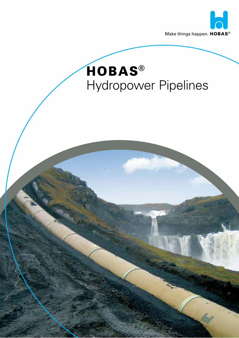
Hydropower Pipelines
2
From the Beginning to this Day...
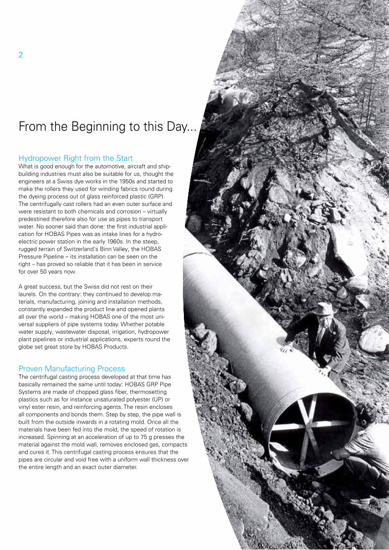
Hydropower Right from the StartWhat is good enough for the automotive, aircraft and ship-building industries must also be suitable for us, thought the engineers at a Swiss dye works in the 1950s and started to make the rollers they used for winding fabrics round during the dyeing process out of glass reinforced plastic (GRP). The centrifugally cast rollers had an even outer surface and were resistant to both chemicals and corrosion – virtually predestined therefore also for use as pipes to transport water. No sooner said than done: the first industrial appli-cation for HOBAS Pipes was as intake lines for a hydro-electric power station in the early 1960s. In the steep, rugged terrain of Switzerland's Binn Valley, the HOBAS Pressure Pipeline – its installation can be seen on the right – has proved so reliable that it has been in service for over 50 years now.
A great success, but the Swiss did not rest on their laurels. On the contrary: they continued to develop ma-terials, manufacturing, joining and installation methods, constantly expanded the product line and opened plants all over the world – making HOBAS one of the most uni-versal suppliers of pipe systems today. Whether potable water supply, wastewater disposal, irrigation, hydropower plant pipelines or industrial applications, experts round the globe set great store by HOBAS Products.
Proven Manufacturing ProcessThe centrifugal casting process developed at that time has basically remained the same until today: HOBAS GRP Pipe Systems are made of chopped glass fiber, thermosetting plastics such as for instance unsaturated polyester (UP) or vinyl ester resin, and reinforcing agents. The resin encloses all components and bonds them. Step by step, the pipe wall is built from the outside inwards in a rotating mold. Once all the materials have been fed into the mold, the speed of rotation is increased. Spinning at an acceleration of up to 75 g presses the material against the mold wall, removes enclosed gas, compacts and cures it. This centrifugal casting process ensures that the pipes are circular and void free with a uniform wall thickness over the entire length and an exact outer diameter.
3
1
2
3
4
5
6
7
8
Sophisticated Pipe Wall Structure for Your Benefit
HOBAS Pipes' unique wall structure offers a whole range of advantages:
Minimal friction and pressure loss due to the extremely smooth inner pipe surface
Less water hammer than with metal pipe materials Resistance to UV light Low weight enabling high installation rates even in less accessible terrain High abrasion resistance Corrosion resistance Variable lengths as pipes can easily be shortened on site Dimensionally accurate outside diameter Angular deflection possible in couplings Consistently high quality with complete internal and external quality
control (testing of material properties, pressure tests, etc.) Low operating and maintenance costs Long service life of more than 50 years Technical service
Our HOBAS Experts are here to support you throughout your project. From inspecting the planned pipe route, selecting the right diameter and creating a digital installation plan through constant supervision of installation activities on the construction site by our pipe consultants – with HOBAS you have a reliable and experienced partner at your side.
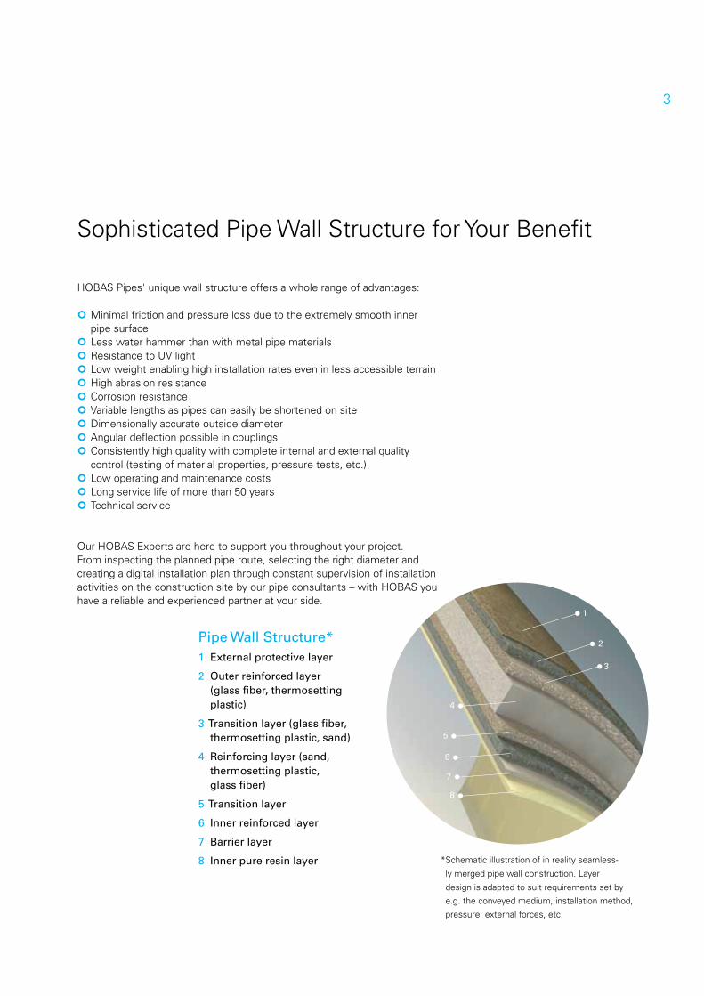
Pipe Wall Structure*1 External protective layer
2 Outer reinforced layer (glass fiber, thermosetting plastic)
3 Transition layer (glass fiber, thermosetting plastic, sand)
4 Reinforcing layer (sand, thermosetting plastic, glass fiber)
5 Transition layer
6 Inner reinforced layer
7 Barrier layer
8 Inner pure resin layer *Schematic illustration of in reality seamless-
ly merged pipe wall construction. Layer
design is adapted to suit requirements set by
e.g. the conveyed medium, installation method,
pressure, external forces, etc.
4
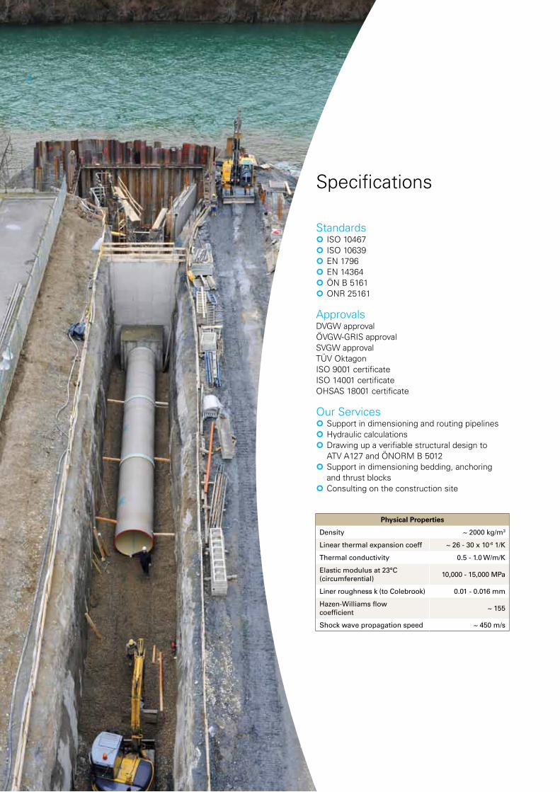
Specifications
Standards ISO 10467 ISO 10639 EN 1796 EN 14364 ÖN B 5161 ONR 25161
ApprovalsDVGW approvalÖVGW-GRIS approvalSVGW approvalTÜV OktagonISO 9001 certificateISO 14001 certificate OHSAS 18001 certificate
Our Services Support in dimensioning and routing pipelines Hydraulic calculations Drawing up a verifiable structural design to
ATV A127 and ÖNORM B 5012 Support in dimensioning bedding, anchoring
and thrust blocks Consulting on the construction site
Physical Properties
Density ~ 2000 kg/m3
Linear thermal expansion coeff ~ 26 - 30 x 10-6 1/K
Thermal conductivity 0.5 - 1.0 W/m/K
Elastic modulus at 23°C (circumferential) 10,000 - 15,000 MPa
Liner roughness k (to Colebrook) 0.01 - 0.016 mm
Hazen-Williams flow coefficient ~ 155
Shock wave propagation speed ~ 450 m/s
5
h Pipe Systems
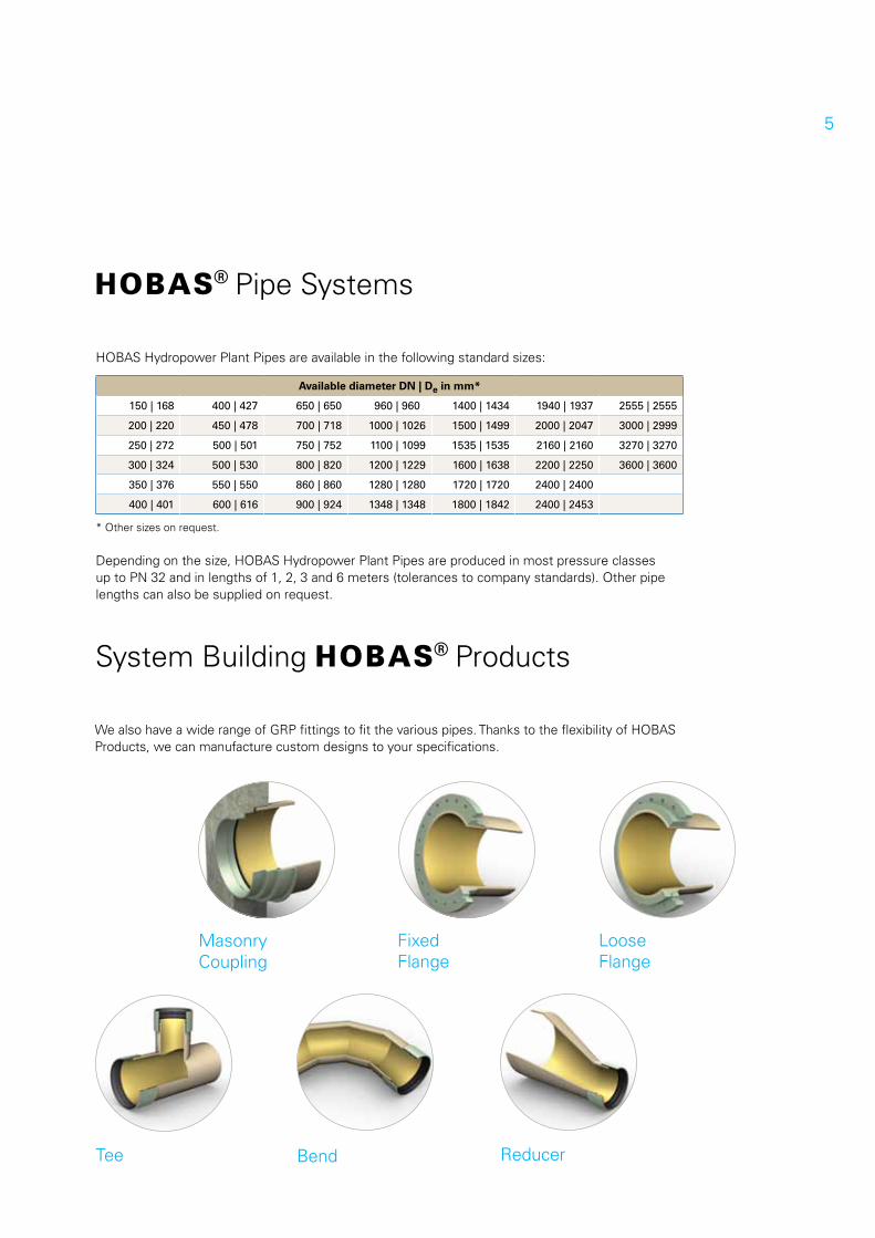
HOBAS Hydropower Plant Pipes are available in the following standard sizes:
* Other sizes on request.
Depending on the size, HOBAS Hydropower Plant Pipes are produced in most pressure classes up to PN 32 and in lengths of 1, 2, 3 and 6 meters (tolerances to company standards). Other pipe lengths can also be supplied on request.
We also have a wide range of GRP fittings to fit the various pipes. Thanks to the flexibility of HOBAS Products, we can manufacture custom designs to your specifications.
System Building h Products
Tee
Masonry Coupling
Reducer
Loose Flange
Bend
Fixed Flange
Available diameter DN | De in mm*
150 | 168 400 | 427 650 | 650 960 | 960 1400 | 1434 1940 | 1937 2555 | 2555
200 | 220 450 | 478 700 | 718 1000 | 1026 1500 | 1499 2000 | 2047 3000 | 2999
250 | 272 500 | 501 750 | 752 1100 | 1099 1535 | 1535 2160 | 2160 3270 | 3270
300 | 324 500 | 530 800 | 820 1200 | 1229 1600 | 1638 2200 | 2250 3600 | 3600
350 | 376 550 | 550 860 | 860 1280 | 1280 1720 | 1720 2400 | 2400
400 | 401 600 | 616 900 | 924 1348 | 1348 1800 | 1842 2400 | 2453
6
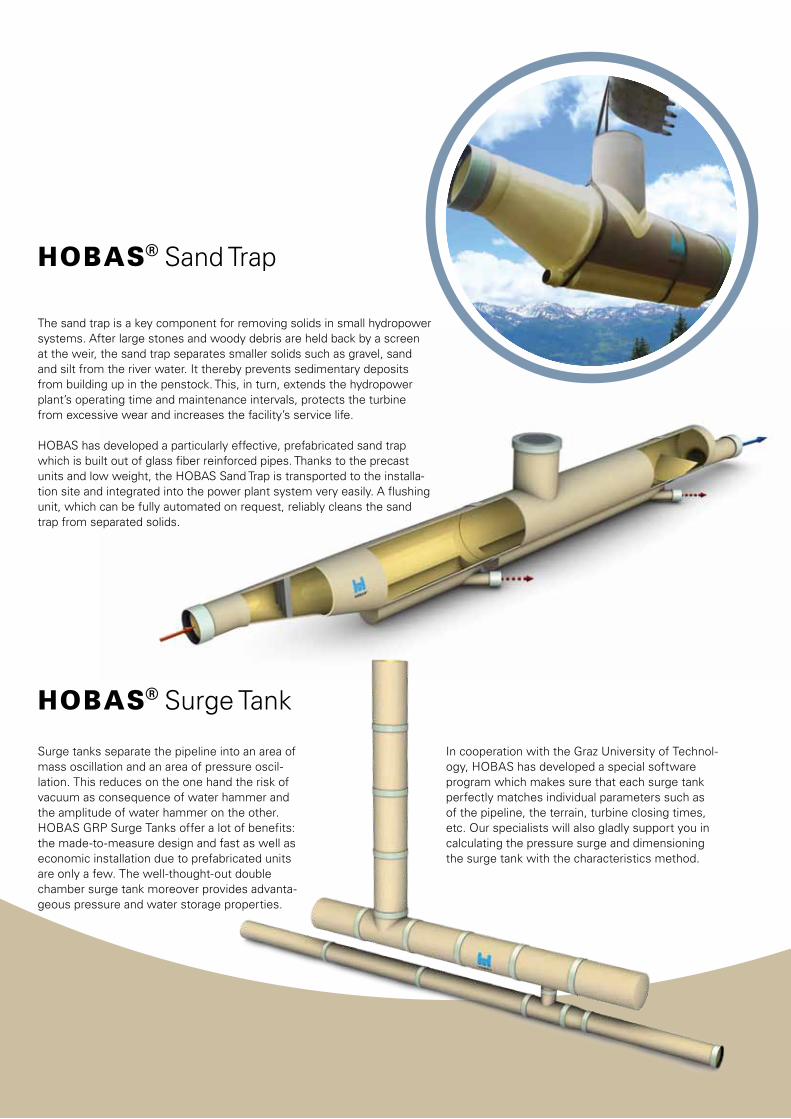
h Surge Tank
Surge tanks separate the pipeline into an area of mass oscillation and an area of pressure oscil-lation. This reduces on the one hand the risk of vacuum as consequence of water hammer and the amplitude of water hammer on the other. HOBAS GRP Surge Tanks offer a lot of benefits: the made-to-measure design and fast as well as economic installation due to prefabricated units are only a few. The well-thought-out double chamber surge tank moreover provides advanta-geous pressure and water storage properties.
In cooperation with the Graz University of Technol-ogy, HOBAS has developed a special software program which makes sure that each surge tank perfectly matches individual parameters such as of the pipeline, the terrain, turbine closing times, etc. Our specialists will also gladly support you in calculating the pressure surge and dimensioning the surge tank with the characteristics method.
The sand trap is a key component for removing solids in small hydropower systems. After large stones and woody debris are held back by a screen at the weir, the sand trap separates smaller solids such as gravel, sand and silt from the river water. It thereby prevents sedimentary deposits from building up in the penstock. This, in turn, extends the hydropower plant’s operating time and maintenance intervals, protects the turbine from excessive wear and increases the facility’s service life.
HOBAS has developed a particularly effective, prefabricated sand trap which is built out of glass fiber reinforced pipes. Thanks to the precast units and low weight, the HOBAS Sand Trap is transported to the installa-tion site and integrated into the power plant system very easily. A flushing unit, which can be fully automated on request, reliably cleans the sand trap from separated solids.
h Sand Trap
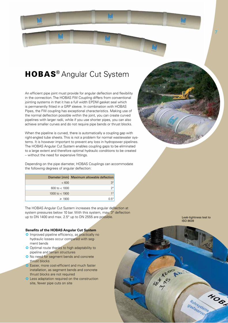
Leak-tightness test to ISO 8639
7
h Angular Cut System
An efficient pipe joint must provide for angular deflection and flexibility in the connection. The HOBAS FW Coupling differs from conventional jointing systems in that it has a full width EPDM gasket seal which is permanently fitted in a GRP sleeve. In combination with HOBAS Pipes, the FW coupling has exceptional characteristics. Making use of the normal deflection possible within the joint, you can create curved pipelines with larger radii, while if you use shorter pipes, you can also achieve smaller curves and do not require pipe bends or thrust blocks.
When the pipeline is curved, there is automatically a coupling gap with right-angled tube sheets. This is not a problem for normal wastewater sys-tems. It is however important to prevent any loss in hydropower pipelines. The HOBAS Angular Cut System enables coupling gaps to be eliminated to a large extent and therefore optimal hydraulic conditions to be created – without the need for expensive fittings.
Depending on the pipe diameter, HOBAS Couplings can accommodate the following degrees of angular deflection:
Diameter [mm] Maximum allowable deflection
< 600 3°
600 to < 1000 2°
1000 to < 1900 1°
1900 0.5°
The HOBAS Angular Cut System increases the angular deflection at system pressures below 10 bar. With this system, max. 3° deflection up to DN 1400 and max. 2.5° up to DN 2555 are possible.
Benefits of the HOBAS Angular Cut System Improved pipeline efficiency, as practically no
hydraulic losses occur compared with seg-ment bends
Optimal route thanks to high adaptability to pipeline and terrain structures
No need for segment bends and concrete thrust blocks
Easier, more cost-efficient and much faster installation, as segment bends and concrete thrust blocks are not required
Less adaptation required on the construction site, fewer pipe cuts on site
8
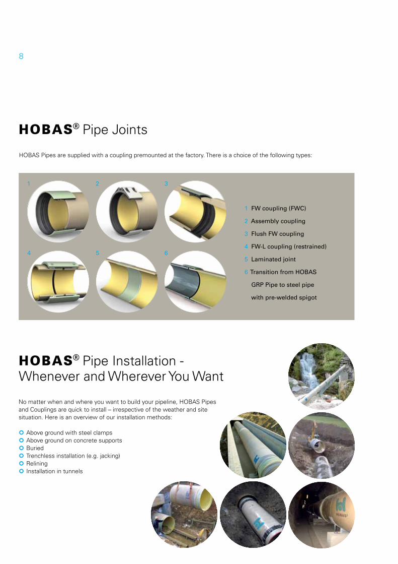
h Pipe Joints
HOBAS Pipes are supplied with a coupling premounted at the factory. There is a choice of the following types:
h Pipe Installation - Whenever and Wherever You Want
No matter when and where you want to build your pipeline, HOBAS Pipes and Couplings are quick to install – irrespective of the weather and site situation. Here is an overview of our installation methods:
Above ground with steel clamps Above ground on concrete supports Buried Trenchless installation (e.g. jacking) Relining Installation in tunnels
1 FW coupling (FWC)
2 Assembly coupling
3 Flush FW coupling
4 FW-L coupling (restrained)
5 Laminated joint
6 Transition from HOBAS
GRP Pipe to steel pipe
with pre-welded spigot
1
4
2
5
3
6
9
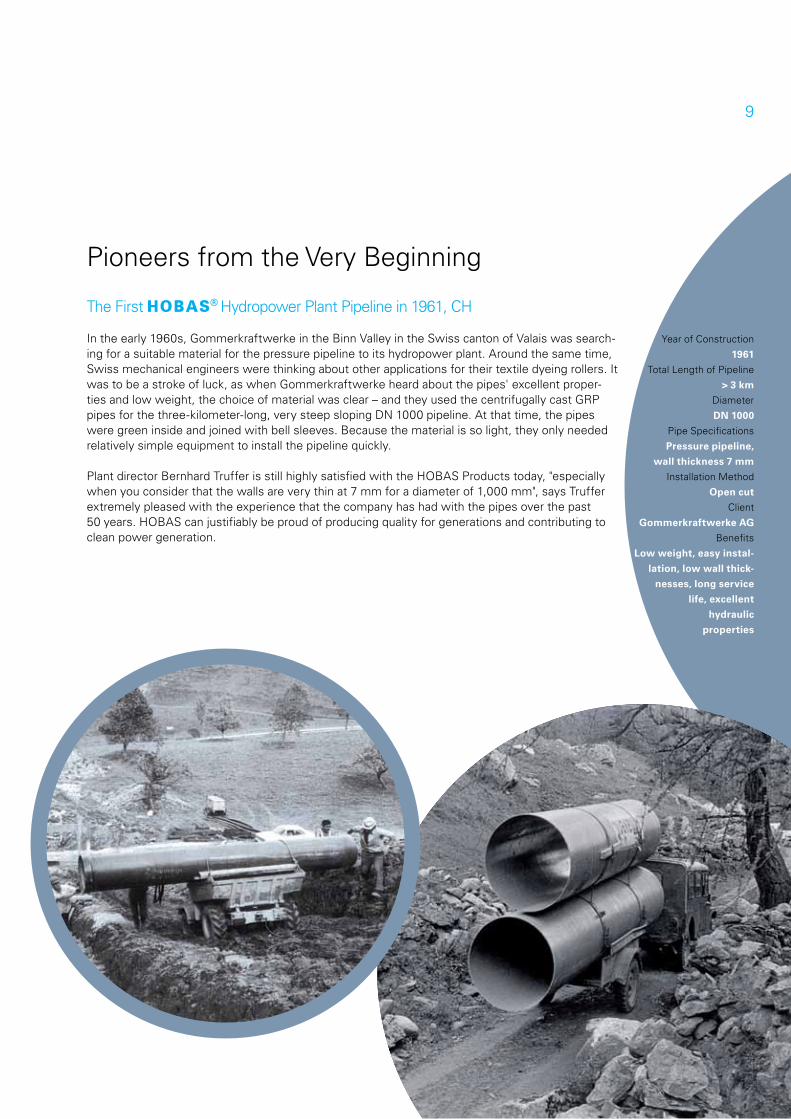
In the early 1960s, Gommerkraftwerke in the Binn Valley in the Swiss canton of Valais was search-ing for a suitable material for the pressure pipeline to its hydropower plant. Around the same time, Swiss mechanical engineers were thinking about other applications for their textile dyeing rollers. It was to be a stroke of luck, as when Gommerkraftwerke heard about the pipes' excellent proper-ties and low weight, the choice of material was clear – and they used the centrifugally cast GRP pipes for the three-kilometer-long, very steep sloping DN 1000 pipeline. At that time, the pipes were green inside and joined with bell sleeves. Because the material is so light, they only needed relatively simple equipment to install the pipeline quickly.
Plant director Bernhard Truffer is still highly satisfied with the HOBAS Products today, "especially when you consider that the walls are very thin at 7 mm for a diameter of 1,000 mm", says Truffer extremely pleased with the experience that the company has had with the pipes over the past 50 years. HOBAS can justifiably be proud of producing quality for generations and contributing to clean power generation.
Year of Construction
1961
Total Length of Pipeline
> 3 km
Diameter
DN 1000
Pipe Specifications
Pressure pipeline,
wall thickness 7 mm
Installation Method
Open cut
Client
Gommerkraftwerke AG
Benefits
Low weight, easy instal-
lation, low wall thick-
nesses, long service
life, excellent
hydraulic
properties
Pioneers from the Very Beginning
The First h Hydropower Plant Pipeline in 1961, CH
10
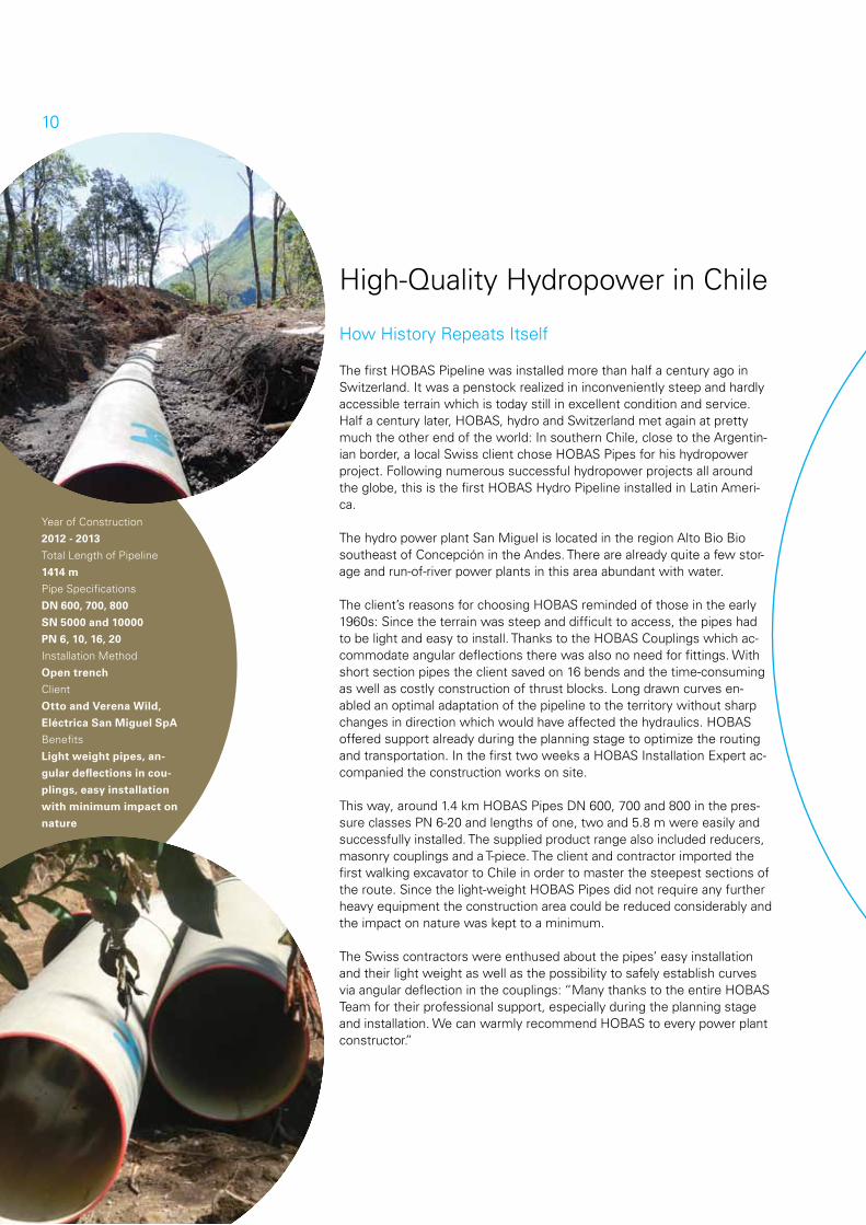
High-Quality Hydropower in Chile
How History Repeats Itself
The first HOBAS Pipeline was installed more than half a century ago in Switzerland. It was a penstock realized in inconveniently steep and hardly accessible terrain which is today still in excellent condition and service. Half a century later, HOBAS, hydro and Switzerland met again at pretty much the other end of the world: In southern Chile, close to the Argentin-ian border, a local Swiss client chose HOBAS Pipes for his hydropower project. Following numerous successful hydropower projects all around the globe, this is the first HOBAS Hydro Pipeline installed in Latin Ameri-ca.
The hydro power plant San Miguel is located in the region Alto Bio Bio southeast of Concepción in the Andes. There are already quite a few stor-age and run-of-river power plants in this area abundant with water.
The client’s reasons for choosing HOBAS reminded of those in the early 1960s: Since the terrain was steep and difficult to access, the pipes had to be light and easy to install. Thanks to the HOBAS Couplings which ac-commodate angular deflections there was also no need for fittings. With short section pipes the client saved on 16 bends and the time-consuming as well as costly construction of thrust blocks. Long drawn curves en-abled an optimal adaptation of the pipeline to the territory without sharp changes in direction which would have affected the hydraulics. HOBAS offered support already during the planning stage to optimize the routing and transportation. In the first two weeks a HOBAS Installation Expert ac-companied the construction works on site.
This way, around 1.4 km HOBAS Pipes DN 600, 700 and 800 in the pres-sure classes PN 6-20 and lengths of one, two and 5.8 m were easily and successfully installed. The supplied product range also included reducers, masonry couplings and a T-piece. The client and contractor imported the first walking excavator to Chile in order to master the steepest sections of the route. Since the light-weight HOBAS Pipes did not require any further heavy equipment the construction area could be reduced considerably and the impact on nature was kept to a minimum.
The Swiss contractors were enthused about the pipes’ easy installation and their light weight as well as the possibility to safely establish curves via angular deflection in the couplings: “Many thanks to the entire HOBAS Team for their professional support, especially during the planning stage and installation. We can warmly recommend HOBAS to every power plant constructor.”
Year of Construction
2012 - 2013
Total Length of Pipeline
1414 m
Pipe Specifications
DN 600, 700, 800
SN 5000 and 10000
PN 6, 10, 16, 20
Installation Method
Open trench
Client
Otto and Verena Wild,
Eléctrica San Miguel SpA
Benefits
Light weight pipes, an-
gular deflections in cou-
plings, easy installation
with minimum impact on
nature
11
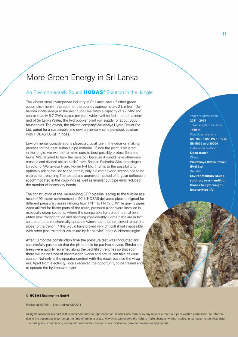
The vibrant small hydropower industry in Sri Lanka saw a further green accomplishment in the south of the country approximately 2 km from De-hilanda in Wellawaya at the river Kuda Oya. With a capacity of 1.2 MW and approximately 5.7 GWh output per year, which will be fed into the national grid of Sri Lanka Water, the hydropower plant will supply for about 6000 households. The owner, the private company Wellawaya Hydro Power Pvt Ltd, opted for a sustainable and environmentally sane penstock solution with HOBAS CC-GRP Pipes.
Environmental considerations played a crucial role in the decision making process for the best suitable pipe material. “Since the plant is situated in the jungle, we wanted to make sure to best possibly protect flora and fauna. We decided to bury the penstock because it would have otherwise crossed and divided animal trails,” says Roshan Prabatha Wickramasinghe, Director of Wellawaya Hydro Power Pvt Ltd. Thanks to the possibility to optimally adapt the line to the terrain, only a 3 meter wide section had to be cleared for trenching. The tested and approved method of angular deflection accommodated in the couplings as well as angular cut pipe ends reduced the number of necessary bends.
The construction of the 1460-m-long GRP pipeline leading to the turbine at a head of 95 meter commenced in 2011. HOBAS delivered pipes designed for different pressure classes ranging from PN 1 to PN 12.5. While gravity pipes were utilized for flatter parts of the route, pressure pipes were installed in especially steep sections, where the comparably light pipe material ben-efited pipe transportation and handling considerably. Some parts are in fact so steep that a mechanically operated winch had to be employed to pull the pipes to the trench. “This would have proved very difficult if not impossible with other pipe materials which are by far heavier,” adds Wickramasinghe.
After 18 months construction time the pressure test was conducted and successfully passed so that the plant could be put into service. Shrubs and trees were quickly replanted along the backfilled trenches so that soon there will be no trace of construction works and nature can take its usual course. Not only is the operator content with the result but also the villag-ers: Apart from electricity, locals received the opportunity to be trained and to operate the hydropower plant.
More Green Energy in Sri Lanka
An Environmentally Sound h Solution in the Jungle
Year of Construction
2011 - 2013
Total Length of Pipeline
1460 m
Pipe Specifications
DN 700 - 1100, PN 1 - 12.5,
SN 5000 and 10000
Installation Method
Open trench
Client
Wellawaya Hydro Power
(Pvt) Ltd
Benefits
Environmentally sound
solution, easy handling
thanks to light weight,
long service life
© E Engineering GmbH
Published: 03/2011 | Last Update: 08/2014
All rights reserved. No part of this document may be reproduced or utilized in any form or by any means without our prior written permission. All informa-
tion in the document is correct at the time of going to press. However, we reserve the right to make changes without notice, in particular to technical data.
The data given is not binding and must therefore be checked in each individual case and revised as appropriate.
11
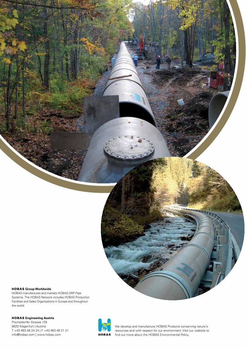
We develop and manufacture HOBAS Products conserving nature‘s resources and with respect for our environment. Visit our website to find out more about the HOBAS Environmental Policy.
E Group WorldwideHOBAS manufactures and markets HOBAS GRP Pipe Systems. The HOBAS Network includes HOBAS Production Facilities and Sales Organizations in Europe and throughout the world.
E Engineering AustriaPischeldorfer Strasse 1289020 Klagenfurt | AustriaT +43.463.48 24 24 | F +43.463.48 21 [email protected] | www.hobas.com