Embed Size (px)
Citation preview
http://123seminarsonly.com/
ABSTRACT
The main objective of this project is to fabricate a robotic trolley for material
handling in industries. In this project a robotic vehicle is fabricated which runs like
a car by carrying tools from place to another. This is done by using a small sensor.
The trolley will stop when the trolley is unloaded.
Find More Project and Seminar Reports
http://123seminarsonly.com/
i
TABLE OF CONTENTS
CHAPTER TITLE PAGE NO.
ABSTRACT i
LIST OF FIGURES ii
1 INTRODUCTION 1
2 WORKING PRINCIPLE 3
3 BLOCK DIAGRAM 5
4 FABRICATION OF PARTS 7
4.1 PMDC MOTOR 8
4.1.1 TORQUE CAPABILITIES
OF MOTOR 13
4.2 RECHARGABLE BATTERY 15
4.2.1 USAGE AND APPLICATIONS 16
4.2.2 CHARGING AND DISCHARGING 17
4.2.3 REVERSE CHARGING 19
4.2.4 BATTERY TYPES 21
4.3 PCB DESIGN 25
4.4 IR SENSOR 29
5 VIEW THROUGH CAMERA 31
6 ADVANTAGES 33
Find More Project and Seminar Reports
http://123seminarsonly.com/
ii
7 APPLICATIONS 35
8 CONCLUSION 37
9 BIBLIOGRAPHY 39
LIST OF FIGURES
No. TITLE PAGE NO.
1 BLOCK DIAGRAM 5
2 DC MOTOR 10
3 IR SENSORS 29
Find More Project and Seminar Reports
http://123seminarsonly.com/
iii
CHAPTER 1 INTRODUCTION
Find More Project and Seminar Reports

http://123seminarsonly.com/
1
INTRODUCTION
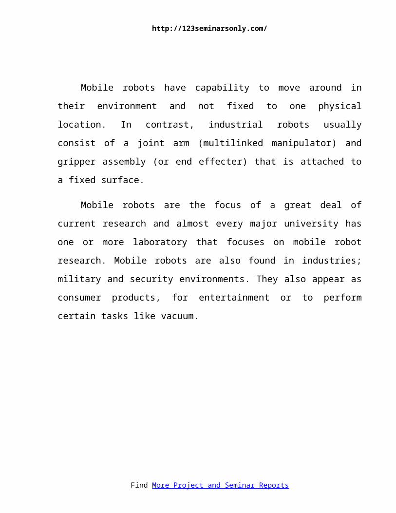
Mobile robots have capability to move around in their environment and not
fixed to one physical location. In contrast, industrial robots usually consist of a
joint arm (multilinked manipulator) and gripper assembly (or end effecter) that is
attached to a fixed surface.
Mobile robots are the focus of a great deal of current research and almost
every major university has one or more laboratory that focuses on mobile robot
research. Mobile robots are also found in industries; military and security
environments. They also appear as consumer products, for entertainment or to
perform certain tasks like vacuum.
Find More Project and Seminar Reports

http://123seminarsonly.com/
2
CHAPTER 2WORKING PRINCIPLE
Find More Project and Seminar Reports
http://123seminarsonly.com/
3
WORKING PRINCIPLE
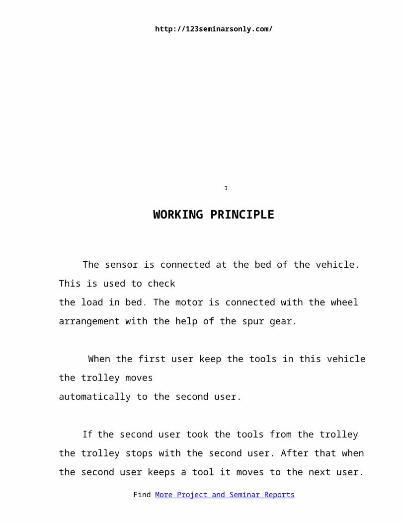
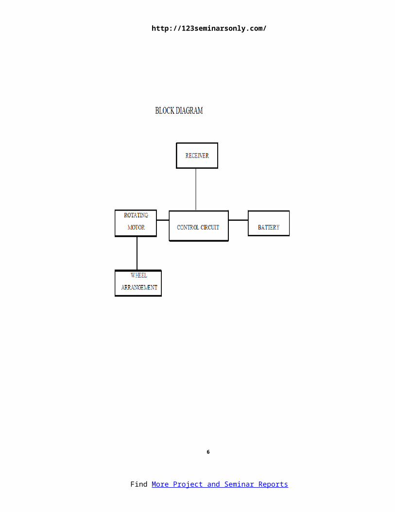
The sensor is connected at the bed of the vehicle. This is used to check
the load in bed. The motor is connected with the wheel arrangement with the help
of the spur gear.
When the first user keep the tools in this vehicle the trolley moves
automatically to the second user.
If the second user took the tools from the trolley the trolley stops with the
second user. After that when the second user keeps a tool it moves to the next user.
It can be used in industries, hospitals etc.
Find More Project and Seminar Reports

http://123seminarsonly.com/
4
CHAPTER 3
BLOCK DIAGRAM
Find More Project and Seminar Reports
http://123seminarsonly.com/
5
Find More Project and Seminar Reports

http://123seminarsonly.com/
6
CHAPTER 4
FABRICATION OF PARTS
Find More Project and Seminar Reports

http://123seminarsonly.com/
7
FABRICATION OF PARTS
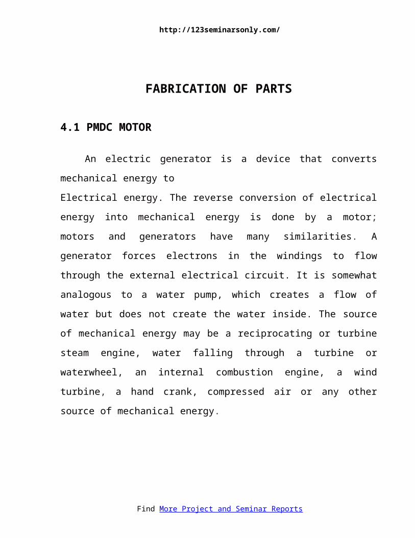
4.1 PMDC MOTOR
An electric generator is a device that converts mechanical energy to
Electrical energy. The reverse conversion of electrical energy into mechanical
energy is done by a motor; motors and generators have many similarities. A
generator forces electrons in the windings to flow through the external electrical
circuit. It is somewhat analogous to a water pump, which creates a flow of water
but does not create the water inside. The source of mechanical energy may be a
reciprocating or turbine steam engine, water falling through a turbine or
waterwheel, an internal combustion engine, a wind turbine, a hand crank,
compressed air or any other source of mechanical energy.
Find More Project and Seminar Reports
http://123seminarsonly.com/
8
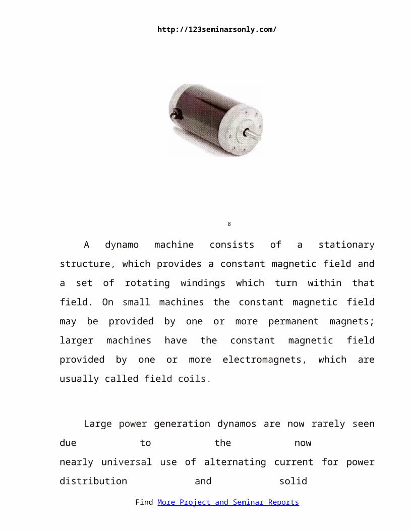
A dynamo machine consists of a stationary structure, which provides a
constant magnetic field and a set of rotating windings which turn within that field.
On small machines the constant magnetic field may be provided by one or more
permanent magnets; larger machines have the constant magnetic field provided by
one or more electromagnets, which are usually called field coils.
Large power generation dynamos are now rarely seen due to the now
nearly universal use of alternating current for power distribution and solid
state electronic AC to DC power conversion. But before the principles of AC
were discovered, very large direct-current· dynamos were the only means of
power generation and distribution. Now power generation dynamos are
mostly a curiosity.
The DC Motor or Direct Current Motor to give it its full title, is the most
commonly used actuator for producing continuous movement and whose speed of
rotation can easily be controlled, making them ideal for use in applications were
Find More Project and Seminar Reports
http://123seminarsonly.com/
speed control, servo type control, and/or positioning is required. A DC motor
consists of two parts, a "Stator" which is the stationary part and a "Rotor" which is
the rotating part. The result is that there are basically three types of DC Motor
available.
Brushed Motor - This type of motor produces a magnetic field in a wound
rotor (the part that rotates) by passing an electrical current through a commutator
and carbon brush assembly, hence the term "Brushed". The stators (the stationary
part) magnetic field is produced by using either a wound stator field winding or by
permanent magnets. Generally brushed DC motors are cheap, small and easily
controlled.
Brushless Motor - This type of motor produce a magnetic field in the rotor
by using permanent magnets attached to it and commutation is achieved
electronically. They are generally smaller but more expensive than conventional
brushed type DC motors because they use "Hall effect” switches in the stator to
produce the required stator field rotational sequence. But they have better
torque/speed characteristics, are more efficient and have
a longer operating life than equivalent brushed types.
Servo Motor - This type of motor is basically a brushed DC motor
with some form of positional feedback control connected to the rotor shaft.
They are connected to and controlled by a PWM type controller and are
mainly used in positional control systems and radio controlled models.
Find More Project and Seminar Reports
http://123seminarsonly.com/
Normal DC motors have almost linear characteristics with their speed
of rotation being determined by the applied DC voltage and their output
torque being determined by the current flowing through the motor windings.
The speed of rotation of any DC motor can be varied from a few revolutions
per minute (rpm) to many thousands of revolutions per minute making them
suitable for electronic, automotive or robotic applications. By connecting
them to gearboxes or gear-trains their output speed can be decreased while at
the same time increasing the torque output of the motor at a high speed.
A conventional brushed DC Motor consist basically of two parts, the
stationary body of the motor called the Stator and the inner part which
rotates producing the movement, called the Rotor or "Armature" for DC machines.
The motors wound stator is an electromagnet which consists of electrical
coils connected together in a circular configuration to produce a North-pole then a
South-pole then a North-pole etc, type stationary magnetic field system (as
opposed to AC machines whose stator field continually rotates with the applied
frequency) with the current flowing within these field coils being known as the
motor field current.
The stators electromagnetic coils can be connected in series, parallel or both
together (compound) with the armature. A series wound DC motor has the stator
field windings connected in series with the armature while a shunt wound DC
motor has the stator field windings connected in parallel with the armature.
Find More Project and Seminar Reports
http://123seminarsonly.com/
The rotor or armature of a DC machine consists of current carrying
conductors connected together at one end to electrically isolated copper segments
called the commutator. The commutator allows an electrical connection to be
made via carbon brushes (hence the name "Brushed" motor) to an external power
supply as the armature rotates. The magnetic field setup by the rotor tries to align
itself with the stationary stator field causing the rotor to rotate on its axis, but
cannot align itself due to commutation delays.
The
rotational speed of the motor is dependent on the strength of the rotors magnetic
field and the more voltage that is applied to the motor the faster the rotor will
rotate. By varying this applied DC voltage the rotational speed of the motor can
also be varied.
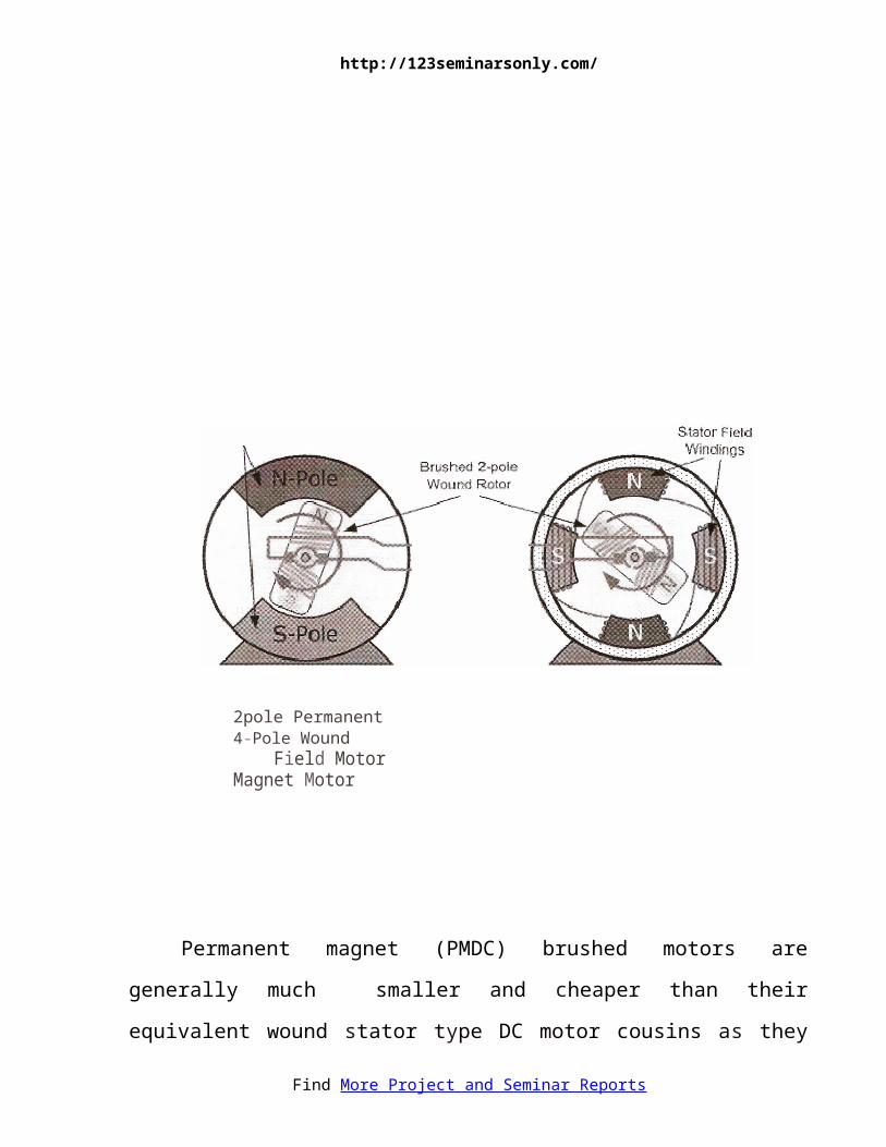
Conventional (Brushed) DC Motor
Permanent magnet
Find More Project and Seminar Reports
http://123seminarsonly.com/
2pole Permanent 4-Pole Wound Field Motor Magnet Motor
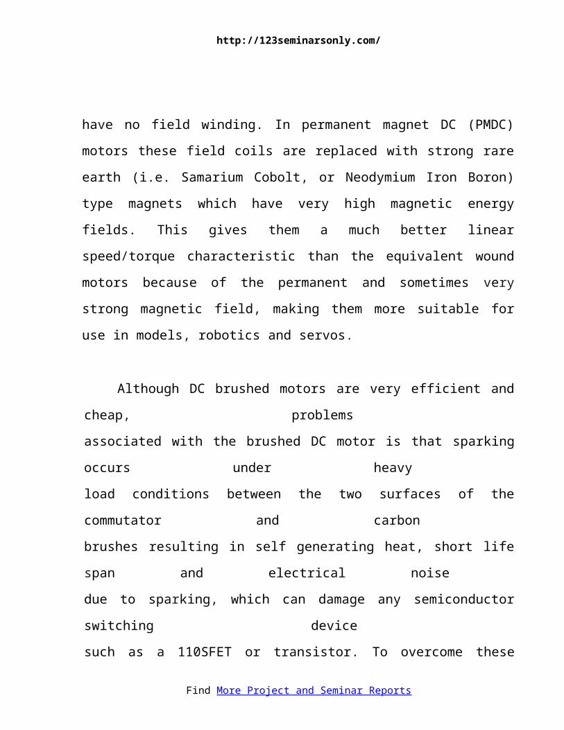
Permanent magnet (PMDC) brushed motors are generally much smaller and
cheaper than their equivalent wound stator type DC motor cousins as they have no
field winding. In permanent magnet DC (PMDC) motors these field coils are
replaced with strong rare earth (i.e. Samarium Cobolt, or Neodymium Iron Boron)
type magnets which have very high magnetic energy fields. This gives them a
much better linear speed/torque characteristic than the equivalent wound motors
because of the permanent and sometimes very strong magnetic field, making them
more suitable for use in models, robotics and servos.
Although DC brushed motors are very efficient and cheap, problems
associated with the brushed DC motor is that sparking occurs under heavy
load conditions between the two surfaces of the commutator and carbon
brushes resulting in self generating heat, short life span and electrical noise
due to sparking, which can damage any semiconductor switching device
such as a 110SFET or transistor. To overcome these disadvantages,
Brushless DC Motors were developed.
Find More Project and Seminar Reports
http://123seminarsonly.com/
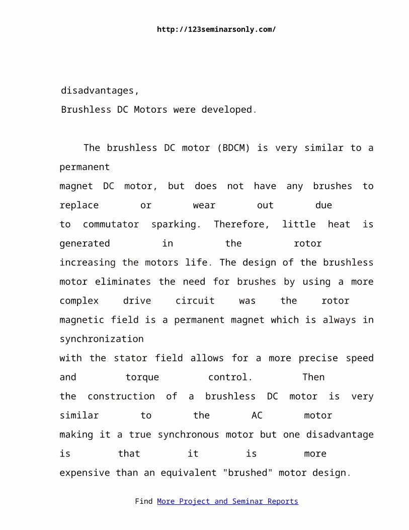
The brushless DC motor (BDCM) is very similar to a permanent
magnet DC motor, but does not have any brushes to replace or wear out due
to commutator sparking. Therefore, little heat is generated in the rotor
increasing the motors life. The design of the brushless motor eliminates the need
for brushes by using a more complex drive circuit was the rotor
magnetic field is a permanent magnet which is always in synchronization
with the stator field allows for a more precise speed and torque control. Then
the construction of a brushless DC motor is very similar to the AC motor
making it a true synchronous motor but one disadvantage is that it is more
expensive than an equivalent "brushed" motor design.
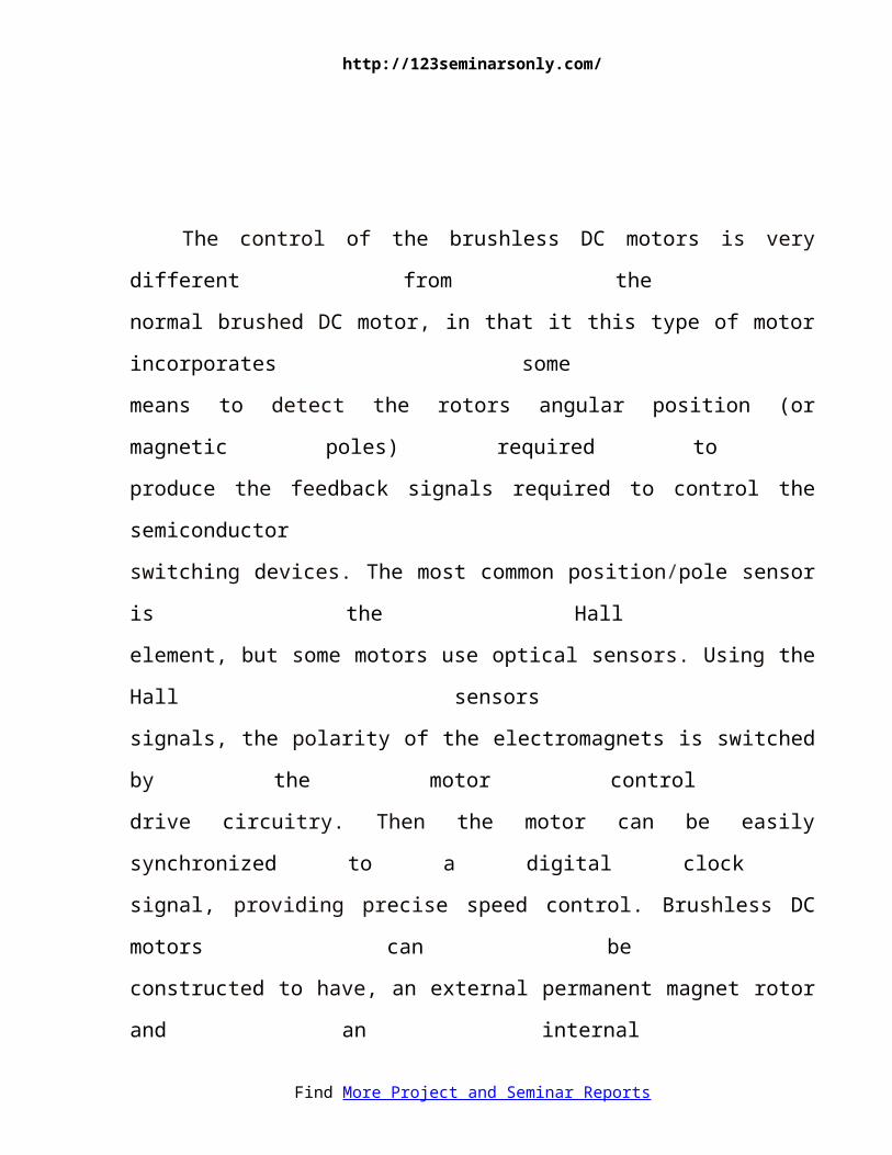
The control of the brushless DC motors is very different from the
normal brushed DC motor, in that it this type of motor incorporates some
means to detect the rotors angular position (or magnetic poles) required to
produce the feedback signals required to control the semiconductor
switching devices. The most common position/pole sensor is the Hall
element, but some motors use optical sensors. Using the Hall sensors
signals, the polarity of the electromagnets is switched by the motor control
drive circuitry. Then the motor can be easily synchronized to a digital clock
signal, providing precise speed control. Brushless DC motors can be
constructed to have, an external permanent magnet rotor and an internal
electromagnet stator or an internal permanent magnet rotor and an external
electromagnet stator.
Find More Project and Seminar Reports
http://123seminarsonly.com/
12
4.1.1 TORQUE CAPABILITIES OF MOTORS
When optimally designed for a given active current (i.e., torque current),
voltage, pole-pair number, excitation frequency (i.e., synchronous speed), and core
flux density, all categories of electric motors or generators will exhibit virtually the
same maximum continuous shaft torque (i.e., operating torque) within a given
physical size of electromagnetic core. Some applications require bursts of torque
beyond the maximum operating torque, such as short bursts of torque to accelerate
an electric vehicle from standstill. Always limited by magnetic core saturation or
safe operating temperature rise and voltage, the capacity for torque bursts beyond Find More Project and Seminar Reports
http://123seminarsonly.com/
the maximum operating torque differs significantly between categories of electric
motors or generators.
Electric machines without a transformer circuit topology, such as Field-
Wound (i.e., electromagnet) or Permanent Magnet (PM) Synchronous electric
machines cannot realize bursts of torque higher than the maximum designed torque
without saturating the magnetic core and rendering any increase in current as
useless. Furthermore, the permanent magnet assembly of PM synchronous electric
machines can be irreparably damaged, if bursts of torque exceeding the maximum
operating torque rating are attempted.
Electric machines with a transformer circuit topology, such as Induction (i.e.,
asynchronous) electric machines, Induction Doubly-Fed electric machines, and
Induction or Synchronous Wound-Rotor Doubly-Fed (WRDF) electric machines,
exhibit very high bursts of torque because the active current (i.e., Magneto-Motive-
Force or the product of current and winding-turns) induced on either side of the
transformer oppose each other and as a result, the active current contributes nothing
to the transformer coupled magnetic core flux density, which would otherwise lead
to core saturation.
Electric machines that rely on Induction or Asynchronous principles short-
circuit one port of the transformer circuit and as a result, the reactive impedance of
the transformer circuit becomes dominant as slip increases, which limits the
magnitude of active (i.e., real) current. Still, bursts of torque that are two to three
times higher than the maximum design torque are realizable.
Find More Project and Seminar Reports
http://123seminarsonly.com/
The Synchronous WRDF electric machine is the only electric machine with a
truly dual ported transformer circuit topology (i.e., both ports independently
excited with no short-circuited port). The dual ported transformer circuit topology
is known to be unstable and requires a multiphase slip-ring-brush assembly to
propagate limited power to the rotor winding set. If a precision means were
available to instantaneously control torque angle and slip for synchronous operation
during motoring or generating while simultaneously providing brushless power to
the rotor winding set the active current of the Synchronous WRDF electric machine
would be independent of the reactive impedance of the transformer circuit and
bursts of torque significantly higher than the maximum operating torque and far
beyond the practical capability of any other type of electric machine would be
realizable. Torque bursts greater than eight times operating torque have been
calculated.
14
4.2 RECHARGEABLE BATTERY
A rechargeable battery (also known as a storage battery) is a group of one or
more secondary cells. Rechargeable batteries use electrochemical reactions that are
electrically reversible. Rechargeable batteries come in many different sizes and use
different combinations of chemicals. Commonly used secondary cell
("rechargeable battery") chemistries are lead acid, nickel cadmium (NiCd), nickel
Find More Project and Seminar Reports
http://123seminarsonly.com/
metal hydride (NiMH), lithium ion (Li-ion), and lithium ion polymer (Li-ion
polymer).
Rechargeable batteries can offer economic and environmental benefits
compared to disposable batteries. Some rechargeable battery types are available in
the same sizes as disposable types. While the rechargeable cells have a higher
initial cost, rechargeable batteries can be recharged many times. Proper selection of
a rechargeable battery system can reduce toxic materials sent to landfills compared
to an equivalent series of disposable batteries. For example, battery manufacturers
of NiMH rechargeable batteries claim a service life of 100-1000 charge cycles for
their batteries.
15
4.2.1 USAGE AND APPLICATIONS
Rechargeable batteries currently are used for applications such as automobile
starters, portable consumer devices, light vehicles (such as motorized wheelchairs,
golf carts, electric bicycles, and electric forklifts), tools, and uninterruptible power
supplies. Emerging applications in hybrid electric vehicles and electric vehicles are
driving the technology to reduce cost, reduce weight, and increase lifetime.
Find More Project and Seminar Reports
http://123seminarsonly.com/
Unlike non-rechargeable batteries (primary cells), rechargeable batteries
have to be charged before use. The need to charge rechargeable batteries before use
deterred potential buyers who needed to use the batteries immediately. However,
new low self discharge batteries allow users to purchase rechargeable battery that
already hold about 70% of the rated capacity, allowing consumers to use the
batteries immediately and recharge later.
Grid energy storage applications use industrial rechargeable batteries for
load leveling, where they store electric energy for use during peak load periods,
and for renewable energy uses, such as storing power generated from photovoltaic
arrays during the day to be used at night. By charging batteries during periods of
low demand and returning energy to the grid during periods of high electrical
demand, load-leveling helps eliminate the need for expensive peaking power plants
and helps amortize the cost of generators over more hours of operation.
The National Electrical Manufacturers Association has estimated that U.S.
demand for rechargeable is growing twice as fast as demand for non rechargeable.
16
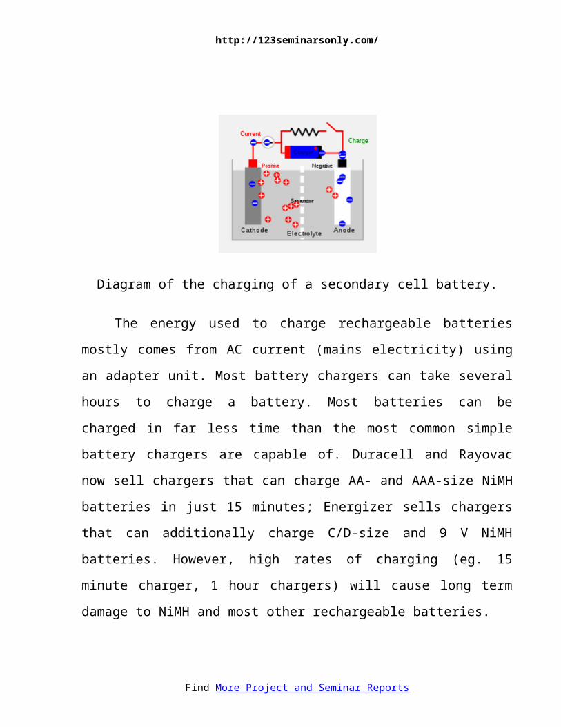
4.2.2 CHARGING AND DISCHARGING
During charging, the positive active material is oxidized, producing
electrons, and the negative material is reduced, consuming electrons. These
electrons constitute the current flow in the external circuit. The electrolyte may
serve as a simple buffer for ion flow between the electrodes, as in lithium-ion and
nickel-cadmium cells, or it may be an active participant in the electrochemical
reaction, as in lead-acid cells.
Find More Project and Seminar Reports
http://123seminarsonly.com/
Diagram of the charging of a secondary cell battery.
The energy used to charge rechargeable batteries mostly comes from AC
current (mains electricity) using an adapter unit. Most battery chargers can take
several hours to charge a battery. Most batteries can be charged in far less time than
the most common simple battery chargers are capable of. Duracell and Rayovac
now sell chargers that can charge AA- and AAA-size NiMH batteries in just 15
minutes; Energizer sells chargers that can additionally charge C/D-size and 9 V
NiMH batteries. However, high rates of charging (eg. 15 minute charger, 1 hour
chargers) will cause long term damage to NiMH and most other rechargeable
batteries.
Battery is susceptible to damage due to reverse charging if they are fully
discharged. Fully integrated battery chargers that optimize the charging current are
available.
Also, attempting to recharge non-rechargeable batteries has a small chance
of causing a battery explosion.
Find More Project and Seminar Reports
http://123seminarsonly.com/
Flow batteries, which are not commonly used by consumers, are recharged
by replacing the electrolyte liquid.
Battery manufacturers' technical notes often refer to VPC. This is volts per
cell, and refers to the individual secondary cells that make up the battery. For
example, to charge a 12 V battery (containing 6 cells of 2 V each) at 2.3 VPC
requires a voltage of 13.8 V across the battery's terminals.
Most NiMH AA or AAA batteries rate their cells at 1.2 V. However, this is
not a problem in most devices because alkaline batteries drop in voltage as the
energy is depleted. Most devices are designed to continue to operate at a reduced
voltage of between 0.9 and 1.1 V
18
4.2.3 REVERSE CHARGING
Reverse charging, which damages batteries, is when a rechargeable battery is
recharged with its polarity reversed. Reverse charging can occur under a number of
circumstances, the three most common being:
When a battery is incorrectly inserted into a charger.
Find More Project and Seminar Reports
http://123seminarsonly.com/
When an automotive type battery charger is connected in reverse to the
battery terminals. This usually occurs when a completely discharged battery
is being charged, otherwise sparking will occur.
When a series string is deeply discharged.
When one cell completely discharges ahead of the rest, the stronger cells will
apply a reverse current to the discharged cell. This is commonly referred to as "cell
reversal". Cell reversal significantly shortens the life of the affected cell and
therefore shortens the overall life of the battery. In some extreme cases, the
reversed cell can begin to emit smoke or catch fire. Some Ni-Cad type cells exhibit
a "memory" effect. Some Ni-Cad type cells that are not fully charged and
discharged periodically can lose their ability to retain a full charge, i.e. exhibit
reduced capacity. Cycling a multi cell battery into deep discharge to overcome this
memory effect can cause cell reversal and do more harm than good. In critical
applications using Ni-Cad batteries, such as in aircraft, each cell is individually
discharged by connecting a load clip across the terminals of each cell, thereby
avoiding cell reversal, then charging the cells in series.
19
DEPTH OF DISCHARGE
Depth of discharge (DOD) is normally stated as a percentage of the nominal
ampere-hour capacity; 0% DOD means no discharge. Since the usable capacity of a
battery system depends on the rate of discharge and the allowable voltage at the
end of discharge, the depth of discharge must be qualified to show the way it is to
Find More Project and Seminar Reports
http://123seminarsonly.com/
be measured. Due to variations during manufacture and aging, the DOD for
complete discharge can change over time / discharge cycles. Generally a
rechargeable battery system will tolerate more charge/discharge cycles if the DOD
is lower on each cycle.
ACTIVE COMPONENTS
Active components in a secondary cell are the chemicals that make up the
positive and negative active materials, and the electrolyte. The positive and
negative are made up of different materials, with the positive exhibiting a reduction
potential and the negative having an oxidation potential. The sum of these
potentials is the standard cell potential or voltage.
In primary cells the positive and negative electrodes are known as the
cathode and anode, respectively. Although this convention is sometimes carried
through to rechargeable systems — especially with lithium-ion cells, because of
their origins in primary lithium cells — this practice can lead to confusion. In
rechargeable cells the positive electrode is the cathode on discharge and the anode
on charge, and vice versa for the negative electrode.
20
4.2.4 COMMON RECHARGEABLE BATTERY TYPES
Nickel-cadmium battery (NiCd)
Created by Waldemar Jungner of Sweden in 1899 which was based on
Thomas Edison's first alkaline battery. Using nickel oxide hydroxide and metallic
Find More Project and Seminar Reports
http://123seminarsonly.com/
cadmium as electrodes. Cadmium is a toxic element, and was banned for most uses
by the European Union in 2004. Nickel-cadmium batteries have been almost
completely superseded by nickel-metal hydride batteries.
Nickel-metal hydride battery (NiMH)
First developed around 1980's. The battery has a hydrogen-absorbing alloy
for the negative electrode instead of cadmium.
Lithium-ion battery
The technology behind lithium-ion battery has not yet fully reached maturity.
However, the batteries are the type of choice in many consumer electronics and
have one of the best energy-to-mass ratios and a very slow loss of charge when not
in use. The popularity of lithium-ion batteries has spread as their technology
continues to improve.
Lithium sulfur battery
A new battery chemistry developed by Sion Power since 1994. Claims
superior energy to weight than current lithium technologies on the market. Also
lower material cost may help this product reach the mass market. Not to be
confused with lithium sulfur dioxide (Li-SO2) batteries which explode when
recharged.
Thin film battery (TFB)
Find More Project and Seminar Reports
http://123seminarsonly.com/
An emerging refinement of the lithium ion technology by Excellatron. The
developers claim a very large increase in recharge cycles, around 40,000 cycles.
Higher charge and discharge rates. At least 5C charge rate. Sustained 60C
discharge, and 1000C peak discharge rate. And also a significant increase in
specific energy, and energy density.
Also Infinite Power Solutions makes thin film batteries (TFB) for micro-
electronics applications that are flexible, rechargeable, solid-state lithium batteries.
Smart battery
A smart battery has the voltage monitoring circuit built inside. Smart Battery
System Carbon foam-based lead acid battery. Firefly Energy has developed a
carbon foam-based lead acid battery with a reported energy density of 30-40%
more than their original 38 Wh/kg, with long life and very high power density.
22
RECENT DEVELOPMENTS
In 2007, assistant professor Yi Cui and colleagues at Stanford University's
Department of Materials Science and Engineering discovered that using silicon
nanowires as the anode increases the volumetric charge density of the anode by up
to a factor of 10. See also ‘Nanowire’ battery. Find More Project and Seminar Reports
http://123seminarsonly.com/
Another development is the invention of flexible batteries, which can be
made paper-thin. Ceramatec, a research and development subcompany of
CoorsTek, is testing a battery which contains a chunk of solid sodium metal mated
to a sulfur compound by an extraordinary, paper-thin ceramic membrane. The
membrane conducts ions back and forth to generate a current. The company claims
that it can cram about 40 kilowatt hours of energy into a package about the size of a
refrigerator, and operate below 90 degrees Celsius. The company also claims that
their battery will allow for 3,650 discharge/recharge cycles (or roughly 1 per day
for one decade.)
23
ALTERNATIVES
Several alternatives to rechargeable batteries exist or are under development. For
uses like portable radios and flashlights, rechargeable batteries may be replaced by
clockwork mechanisms or dynamos which are cranked by the user to provide
power. For transportation, uninterruptible power supply systems and laboratories,
flywheel energy storage systems store energy in a spinning rotor for reconversion
Find More Project and Seminar Reports
http://123seminarsonly.com/
to electric power when needed; such systems may be used to provide large pulses
of power that would otherwise be objectionable on a common electrical grid.
A future development could be ultracapacitors for transportation, using a large
capacitor to store energy instead of the rechargeable battery banks used in hybrid
vehicles. One drawback to capacitors compared with batteries is that the terminal
voltage drops rapidly; a capacitor that has 25% of its initial energy left in it will
have one-half of its initial voltage. Battery systems tend to have a terminal voltage
that does not decline rapidly until nearly exhausted. This characteristic complicates
the design of power electronics for use with ultracapacitors. However, there are
potential benefits in cycle efficiency, lifetime, and weight compared with
rechargeable systems.
24
4.3 PCB DESIGN
The PCB des ign s tar t s r ight f rom the se lec t ion of the
laminates .The two main types of base laminate are epoxy glass
and phenol ic paper laminates are genera l ly used for s imple
Find More Project and Seminar Reports
http://123seminarsonly.com/
ci rcui ts . Though i t i s very cheap and can eas i ly be dr i l led ,
phenol ic paper has poor e lec tr ica l charac te r i s t ics and i t absorbs
more mois ture than epoxy glass . Epoxy glass has h igher
mechanica l s t rength .
The impor tant proper t ies tha t have to be cons idered for
se lec t ing the PCB subst ra te are the d ie lec t r ic s t rength , insula t ion
res is tance , water absorpt ion proper ty , coef f . of thermal
expans ion, shear s t rength , hardness , d imensiona l s tabi l i ty e tc .
4.3 .1 PCB Fabricat ion
The fabr ica t ion of a PCB includes four s teps .
a) Prepar ing the PCB pat tern .
b) Transfer r ing the pa t te rn onto the PCB.
c) Developing the PCB.
d) Finishing ( i .e . ) dr i l l ing , cut t ing , smoothing, turning e tc .2 5
Pat tern des igning i s the pr imary s tep in fabr ica t ing a PCB. In
th is s tep , a l l in terconnect ion between the components in the g iven
c i rcui t a re conver ted in to PCB t racks . Severa l fac tors such as
posi t ioning the d iameter of holes , the area tha t each component
would occupy, the type of end terminal should be cons idered.
Find More Project and Seminar Reports
http://123seminarsonly.com/
Transferring the PCB Pattern
The copper s ide of the PCB should be thoroughly c leaned
wi th the help of a lcohol ic sp i r i t or pe t ro l . I t mus t be comple te ly
f ree f rom dus t and o ther contaminants .
The mir ror image of the pat tern must be carbon copied and to
the laminate the comple te pa t te rn may now be made each res is tant
wi th the help of pa in t and th in brush.
Developing
In th is developing a l l excess ive copper i s removed from the
board and only the pr in ted pat tern i s le f t behind. About 100ml of
tap water should be heated to 75 ° C and 30.5 grams of FeCl 3
added to i t , the mixture should be thoroughly s t i r red and a few
drops of HCl may be added to speed up the process .
2 6
The board wi th i t s copper s ide fac ing upward should be p laced
in a f la t bot tomed plas t ic t ray and the aqueous solu t ion of FeCl 2
poured in the e tching process would take 40 to 60 min to
comple te .
Afte r e tching the board i t should be washed under running
water and then he ld agains t l ight . the pr in ted pat tern should be
Find More Project and Seminar Reports
http://123seminarsonly.com/
clear ly v is ib le . The pain t should be removed wi th the help of
th inner .
Finishing Touches
After the e tching i s comple ted , hole of su i table d iamete r
should be dr i l led , then the PCB may be t in p la ted us ing an
ordinary 35 Wat ts so lder ing rod a long with the solder core , the
copper s ide may be g iven a coat of varnish to prevent oxida t ion .
Dri l l ing
Dri l l s for PCB use usual ly come wi th e i ther a se t of col lec ts
of var ious s izes or a 3-Jaw chuck. For accuracy however 3- jaw
chunks aren’ t br i l l iant and smal l dr i l l be low 1 mm from grooves
in the jaws prevent ing good gr ips .
2 7
Soldering
Begin the const ruct ion by solder ing the res is tors fo l lowed by
the capaci tors and the LEDs diodes and IC sockets . Don’t t ry
so lder ing an IC di rec t ly unless you t rus t your sk i l l in so lder ing.
Al l components should be soldered as shown in the f igure . Now
connect the swi tch and then solder / screw i f on the PCB using Find More Project and Seminar Reports
http://123seminarsonly.com/
mult ip le washers or spaces . Solder ing i t d i rec t ly wi l l only reduce
i t s he ight above o ther components and hamper in i t s easy f ixa t ion
in the cabinet . Now connect the bat tery lead .
Assembl ing
The c i rcui t can be enclosed in any kind of cabinet . Before
f i t t ing the PCB sui table holes must be dr i l led in the cabinet for
the swi tch , LED and buzzer . Note tha t a ro tary swi tch can be used
ins tead of a s l ide type .
Swi tch on the c i rcui t to be desi red range. I t wi l l
automat ica l ly s tar t i t s t iming cycles . To be sure tha t i t i s working
proper ly watch the LED f lash . The components are se lec ted to
t r igger the a larm a few minutes before the se t l imi t .
28
4.4 IR SENSORS
Infrared (IR) light is electromagnetic radiation with a wavelength longer than that of visible light, measured from the nominal edge of visible red light at 0.7 micrometers, and extending conventionally to 300 micrometers. These wavelengths correspond to a frequency range of approximately 430 to 1THz,[1] and include most of the thermal radiation emitted by objects near room temperature.
Find More Project and Seminar Reports
http://123seminarsonly.com/
Microscopically, IR light is typically emitted or absorbed by molecules when they change their rotational-vibration movements.
29
One is an infrared FM transmitter in which audio information is used to modulate the chopping frequency (30 to 250 KHz) of an infrared beam emitted by a set of LEDs.
The transmitter is capable of driving up to 50 to 60 LEDs depending on configuration (Total of 250-300 mA maximum, typically 8 sets of seven series connected IR LEDs) See our article on Infrared Illuminators for more information.
Find More Project and Seminar Reports
http://123seminarsonly.com/
This FM method is far superior to ordinary AM methods where the IR beam is amplitude modulated; being less susceptible to stray "noise" from 60 Hz AC operated lamps. The transmitter and receiver can be operated from 12 volt supplies so that eight AA cells can be used as a simple power source, since only 50 ma is needed. The transmitter kit contains two IR LEDs, which is sufficient for many applications
The receiver unit consists of a IR sensitive photodiode detector and a special FM receiver with a nominal frequency range of 30 to 250 kHz, having a sensitivity of around one microvolt. A phase locked loop (PLL) detector recovers the audio and feeds it to an audio power amplifier with up to 500 milliwatts of audio output. Audio quality is excellent. Range is up to 100 feet without optics, a few hundred feet with simple lenses and with suitable optics such as parabolic mirrors and telescopes, ranges up to a few miles are possible.
It contains PC boards and all parts that are needed to complete one transmitter and one receiver. Two may be used if two channels are needed for stereo. Applications include wireless audio links, private listening devices for TV and radio, IR communications links, fiber optic and infrared experiments, and other experiments with infrared and optics. Since no radio signals are involved, no FCC licensing is necessary.
Find More Project and Seminar Reports
http://123seminarsonly.com/
CHAPTER 5VIEW THROUGH CAMERA
31
Find More Project and Seminar Reports
http://123seminarsonly.com/
Photo
32
Find More Project and Seminar Reports
http://123seminarsonly.com/
CHAPTER 6ADVANTAGES
33
Find More Project and Seminar Reports
ADVANTAGES
Less manpower is needed
Implementation is easy
Fabrication coast is less
User friendly
34
http://123seminarsonly.com/
CHAPTER 7APPLICATION
35
http://123seminarsonly.com/
APPLICATION
It can be used in industries
It can be used in libraries
36
http://123seminarsonly.com/
CHAPTER 8CONCLUSION
37
http://123seminarsonly.com/
CONCLUSION
We have designed and fabricated a robotic trolley for material handling in
industries. With the help this trolley one can move tools from one place to another
or from one user to another. This is done with the help of a sensor and a motor.
We have carried much confidence in doing this project successfully. We
have learn about analysis of a problem, how to solve it, design of the trolley,
design of parts ,fabrication of parts, material purchase, assembling of parts and
successful testing robotic trolley.
38
http://123seminarsonly.com/
CHAPTER 9 BIBLIOGRAPHY
39

http://123seminarsonly.com/
BIBLIOGRAPHY
Robot Tactile Sensing:
R. Andrew Russell (1990)
Fundamentals of Mechanics of Robotic Manipulators:
Marco Ceccarelli
Robotics: Control, Sensing, Vision, and Intelligence:
K. S. Fu & R.C. Gonzalez & C.S.G. Lee
The Robot Chronicles:
Asimov, Isaac (1996) [1995]
40