Embed Size (px)
Citation preview
14th Crystal Ball MeetingEdinburgh
September 13.-15. 2009Andreas Thomas
Overview installation of Polarized Target
0.- Hydrogen Target Length
1.- Polarized target tests
2.- Rail System for ‘Frozen Spin’ mode
3.- CB Frame / Electronics
4.- Schedule
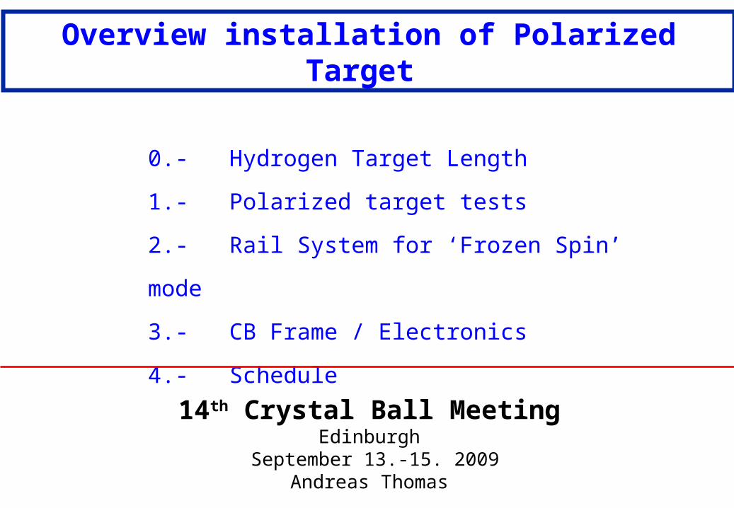
Note: Hydrogen Target Length
New Xray picture of 30mm cell at 9.9.09[R.Kondratiev, O.Kostikov, A.Thomas]
Results:
3 cm cell 30.2 +- 0.3 mm h - Bump 5 cm cell 47.2 +- 0.5 mm standard10 cm cell 100.0 +- 1.0 mm High luminosity
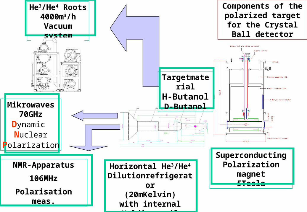
He3/He4 Roots4000m3/h
Vacuum system
Mikrowaves70GHz
Dynamic Nuclear
Polarization
NMR-Apparatus
106MHz
Polarisation meas.
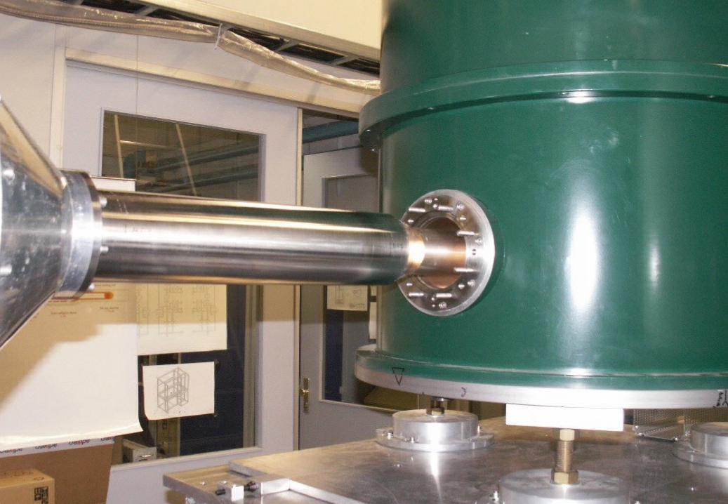
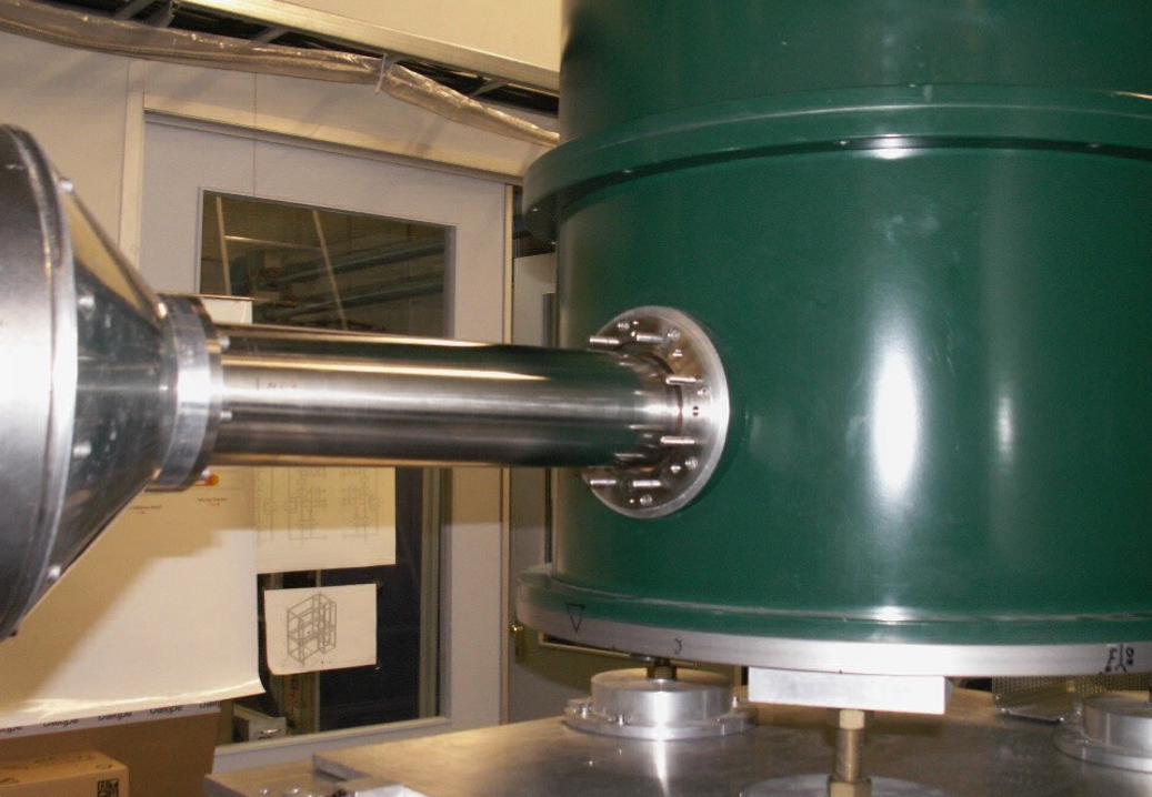
Components of the polarized target
for the Crystal Ball detector
Horizontal He3/He4 Dilutionrefrigerator
(20mKelvin)with internalHolding coil
SuperconductingPolarization magnet
5Tesla
TargetmaterialH-ButanolD-Butanol

· Current leads (46A): Copper T=300K 70 KHTc Supracond. T= 70K 4 K
NbTi 200mm T= 4K 1.5K
Internal
Holding coil
1.3Kelvin
??? Tesla at 46AL=136mm, d=48mm, 4 layersSupport Copper-tube d=0.3mm

Full test with new insert and butanol target in June – July 2009
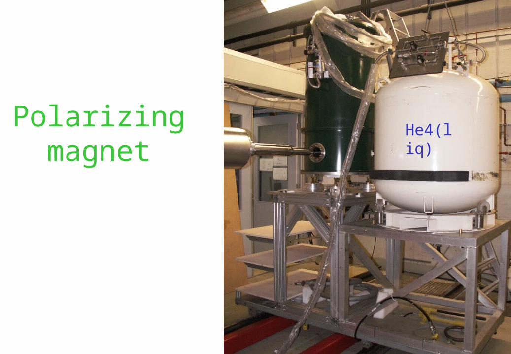
Polarizingmagnet
He4(liq)
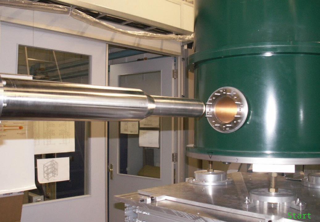
Start
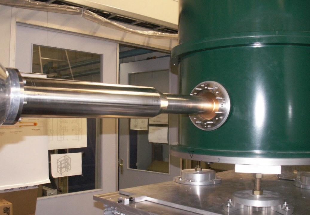
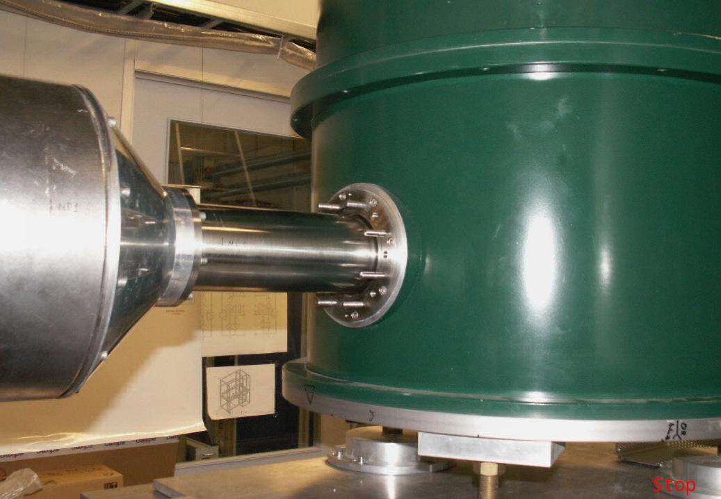
Stop
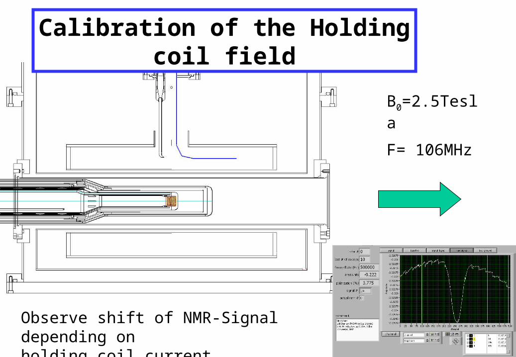
Calibration of the Holding coil field
B0=2.5Tesla
F= 106MHz
Observe shift of NMR-Signal depending onholding coil current

46A ~ 0.895Tesla
B0=2.5Tesla
F= 106MHz

Internal transverse Holding coil
Coil tested at 4.2KHenry OrtegaStarted PhD in Mainz
Different layers areused tooptimize thehomogeniety.

Simulation
• “Racetrack” coil: magnetic field highly non-uniform and not appropriate for a cylinder.
• “Saddle” coil: winding must fit to the so-called overlapping ellipse or “cosine” shape of current distribution (Wilson 2002 & Ašner 1999).
Ideal case for dipole magnet:
cos)(J
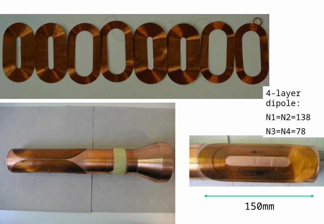
150mm
4-layer dipole:
N1=N2=138
N3=N4=78
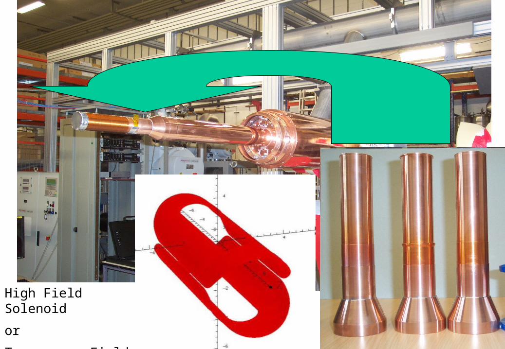
High Field Solenoid
or
Transverse Field

The degree of polarization PT of the target protons (run in May ´98) :
Measurement of the degree of proton polarizationwith online NMR during GDH data taking
New NMR [N.Frömmgen]
physET
PBP
aN
pN
aN
pN
measE

Rail system needed
Cryostat
Polarizingmagnet
Crystal Ball
Polarization method
1. External magnet 2.5 T2. Polarize with microwaves3. Internal holding coil 0.7 T4. Remove external magnet5. Move CB detector in. 6. Data taking.7. Repolarization
Polarizingmagnet
MicrowavesMicrowaves + NMR
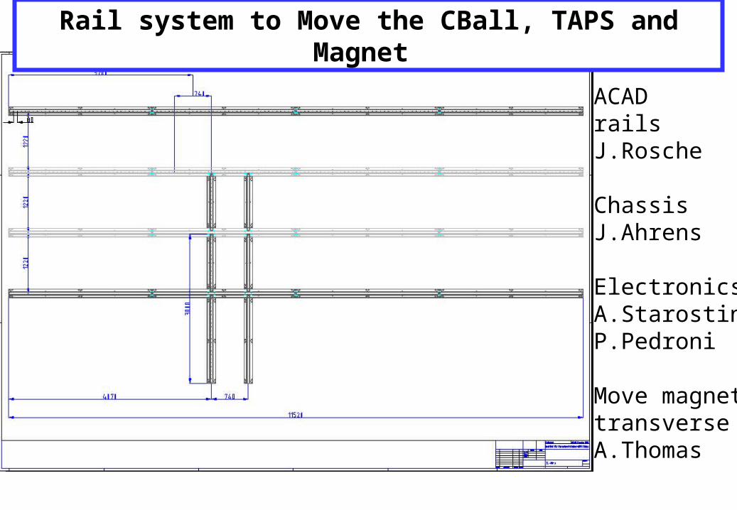
Rail system to Move the CBall, TAPS and Magnet
ACAD railsJ.Rosche
ChassisJ.Ahrens
ElectronicsA.StarostinP.Pedroni
Move magnettransverseA.Thomas
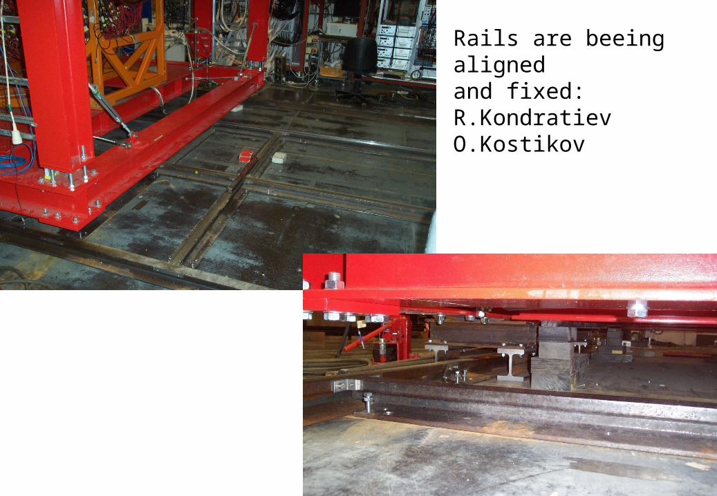
Rails are beeing alignedand fixed:R.KondratievO.Kostikov
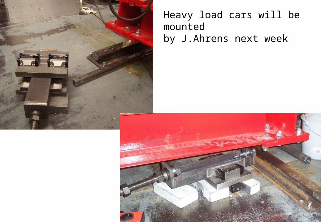
Heavy load cars will be mountedby J.Ahrens next week
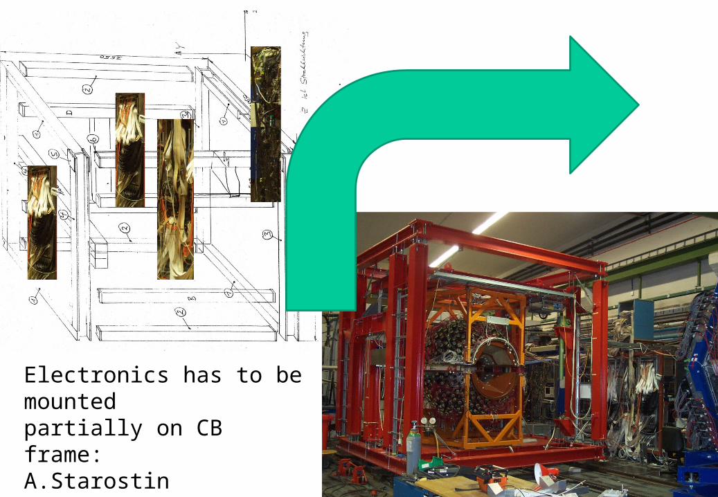
Electronics has to be mountedpartially on CB frame:A.StarostinA.LapikM. Korolija
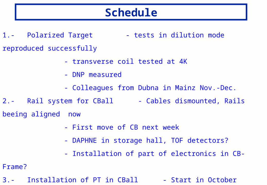
Schedule
1.- Polarized Target - tests in dilution mode reproduced successfully
- transverse coil tested at 4K
- DNP measured
- Colleagues from Dubna in Mainz Nov.-Dec.
2.- Rail system for CBall - Cables dismounted, Rails beeing aligned now
- First move of CB next week
- DAPHNE in storage hall, TOF detectors?
- Installation of part of electronics in CB-Frame?
3.- Installation of PT in CBall - Start in October
- Test beam in December for intensity
dependent relaxation time etc.
- Transverse or Longitudinal coil.