Embed Size (px)
Citation preview
CHAPTER14IEEE 802.11 WIRELESSLAN STANDARD
14.1 IEEE 802 Architecture
Protocol ArchitectureMAC Frame FormatLogical Link Control
14.2 IEEE 802.11 Architecture and Services
IEEE 802.11 ArchitectureIEEE 802.11 Services
14.3 IEEE 802.11 Medium Access Control
Reliable Data DeliveryAccess ControlMAC FrameSecurity Considerations
14.4 IEEE 802.11 Physical Layer
Original IEEE 802.11 Physical LayerIEEE 802.11aIEEE 802.11b
14.5 Recommended Reading and Web Sites
14.6 Key Terms and Review Questions
14 StallingsIII 5/31/01 9:02 PM Page 449
450 CHAPTER 14 / IEEE 802.11 WIRELESS LAN STANDARD
1See Appendix A for a discussion of the IEEE 802 Standards Committee.
The most prominent specification for wireless LANs was developed bythe IEEE 802.11 working group. We look first at the overall architecture ofIEEE 802 standards and then at the specifics of IEEE 802.11.
14.1 IEEE 802 ARCHITECTURE
The architecture of a LAN is best described in terms of a layering of protocols thatorganize the basic functions of a LAN. This section opens with a description of thestandardized protocol architecture for LANs, which encompasses physical, mediumaccess control, and logical link control layers. We then look in more detail atmedium access control and logical link control.
Protocol Architecture
Protocols defined specifically for LAN and MAN (metropolitan area network)transmission address issues relating to the transmission of blocks of data over thenetwork. In OSI terms, higher-layer protocols (layer 3 or 4 and above) are inde-pendent of network architecture and are applicable to LANs, MANs, and WANs.Thus, a discussion of LAN protocols is concerned principally with lower layers ofthe OSI model.
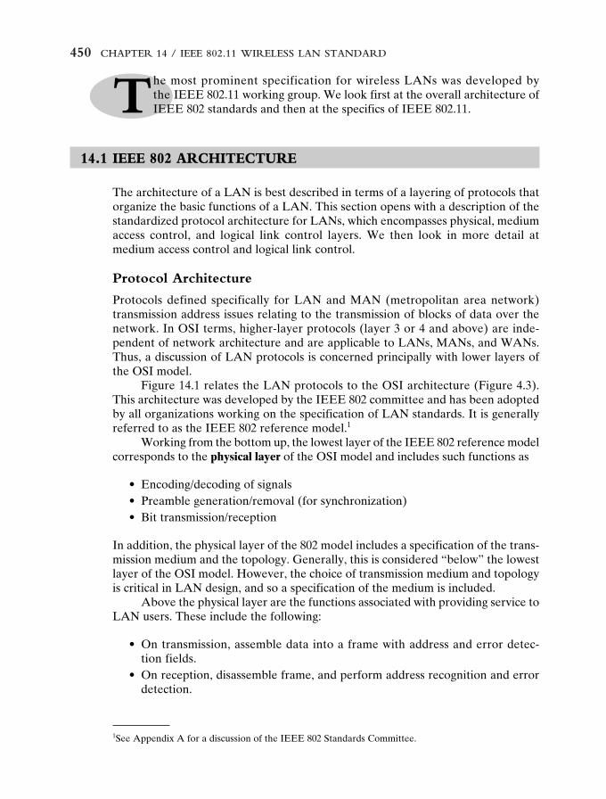
Figure 14.1 relates the LAN protocols to the OSI architecture (Figure 4.3).This architecture was developed by the IEEE 802 committee and has been adoptedby all organizations working on the specification of LAN standards. It is generallyreferred to as the IEEE 802 reference model.1
Working from the bottom up, the lowest layer of the IEEE 802 reference modelcorresponds to the physical layer of the OSI model and includes such functions as
• Encoding/decoding of signals• Preamble generation/removal (for synchronization)• Bit transmission/reception
In addition, the physical layer of the 802 model includes a specification of the trans-mission medium and the topology. Generally, this is considered “below” the lowestlayer of the OSI model. However, the choice of transmission medium and topologyis critical in LAN design, and so a specification of the medium is included.
Above the physical layer are the functions associated with providing service toLAN users. These include the following:
• On transmission, assemble data into a frame with address and error detec-tion fields.
• On reception, disassemble frame, and perform address recognition and errordetection.
14 StallingsIII 5/31/01 9:02 PM Page 450
14.1 / IEEE 802 ARCHITECTURE 451
Physical
Data link
Medium
Network
Transport
Session
Presentation
Application
OSI referencemodel
Physical
Medium accesscontrol
Medium
Logical link control( ) ( ) ( )
Upper-layer
protocolsLLC serviceaccess point
(LSAP)
Scopeof
IEEE 802standards
IEEE 802reference
model
Figure 14.1 IEEE 802 Protocol Layers Compared to OSI Model
• Govern access to the LAN transmission medium.• Provide an interface to higher layers and perform flow and error control.
These are functions typically associated with OSI layer 2. The set of functionsin the last bullet item are grouped into a logical link control (LLC) layer. The func-tions in the first three bullet items are treated as a separate layer, called mediumaccess control (MAC). The separation is done for the following reasons:
• The logic required to manage access to a shared-access medium is not foundin traditional layer 2 data link control.
• For the same LLC, several MAC options may be provided.
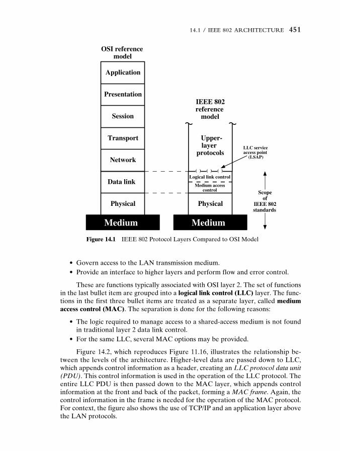
Figure 14.2, which reproduces Figure 11.16, illustrates the relationship be-tween the levels of the architecture. Higher-level data are passed down to LLC,which appends control information as a header, creating an LLC protocol data unit(PDU). This control information is used in the operation of the LLC protocol. Theentire LLC PDU is then passed down to the MAC layer, which appends controlinformation at the front and back of the packet, forming a MAC frame. Again, thecontrol information in the frame is needed for the operation of the MAC protocol.For context, the figure also shows the use of TCP/IP and an application layer abovethe LAN protocols.
14 StallingsIII 5/31/01 9:02 PM Page 451
452
TC
P s
egm
ent
IP d
atag
ram
LL
C p
roto
col d
ata
unit
MA
C f
ram
e
App
licat
ion
data
TC
Phe
ader
IPhe
ader
LL
Che
ader
MA
Che
ader
MA
Ctr
aile
r
App
licat
ion
laye
r
TC
P la
yer
IP la
yer
LL
C la
yer
MA
C la
yer
Fig
ure
14.2
IEE
E 8
02 P
roto
cols
in C
onte
xt
14 StallingsIII 5/31/01 9:03 PM Page 452
14.1 / IEEE 802 ARCHITECTURE 453
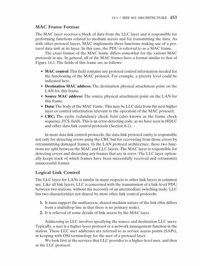
MAC Frame Format
The MAC layer receives a block of data from the LLC layer and is responsible forperforming functions related to medium access and for transmitting the data. Aswith other protocol layers, MAC implements these functions making use of a pro-tocol data unit at its layer. In this case, the PDU is referred to as a MAC frame.
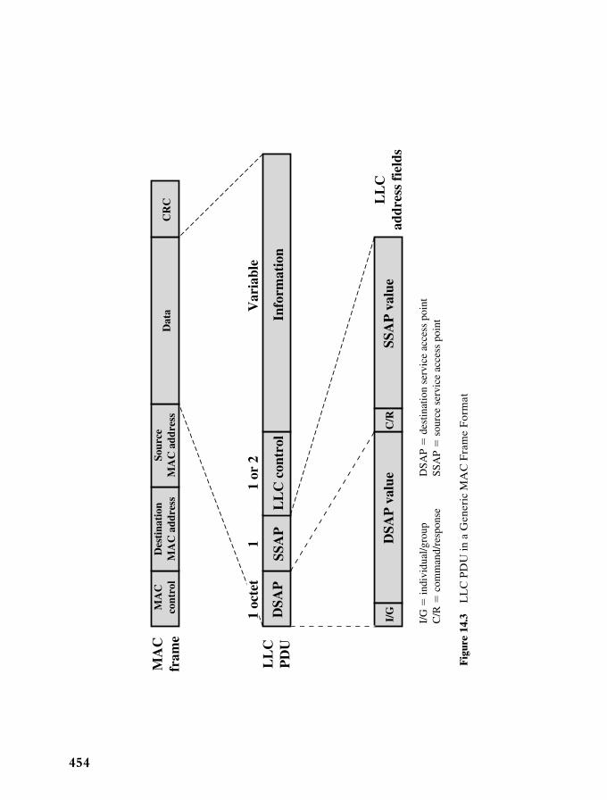
The exact format of the MAC frame differs somewhat for the various MACprotocols in use. In general, all of the MAC frames have a format similar to that ofFigure 14.3. The fields of this frame are as follows:
• MAC control: This field contains any protocol control information needed forthe functioning of the MAC protocol. For example, a priority level could beindicated here.
• Destination MAC address: The destination physical attachment point on theLAN for this frame.
• Source MAC address: The source physical attachment point on the LAN forthis frame.
• Data: The body of the MAC frame. This may be LLC data from the next higherlayer or control information relevant to the operatoin of the MAC protocol.
• CRC: The cyclic redundancy check field (also known as the frame checksequence, FCS, field). This is an error-detecting code, as we have seen in HDLCand other data link control protocols (Section 8.1).
In most data link control protocols, the data link protocol entity is responsiblenot only for detecting errors using the CRC but for recovering from those errors byretransmitting damaged frames. In the LAN protocol architecture, these two func-tions are split between the MAC and LLC layers. The MAC layer is responsible fordetecting errors and discarding any frames that are in error. The LLC layer option-ally keeps track of which frames have been successfully received and retransmitsunsuccessful frames.
Logical Link Control
The LLC layer for LANs is similar in many respects to other link layers in commonuse. Like all link layers, LLC is concerned with the transmission of a link-level PDUbetween two stations, without the necessity of an intermediate switching node. LLChas two characteristics not shared by most other link control protocols:
1. It must support the multiaccess, shared-medium nature of the link (this differsfrom a multidrop line in that there is no primary node).
2. It is relieved of some details of link access by the MAC layer.
Addressing in LLC involves specifying the source and destination LLC users.Typically, a user is a higher-layer protocol or a network management function in thestation. These LLC user addresses are referred to as service access points (SAPs),in keeping with OSI terminology for the user of a protocol layer.
We look first at the services that LLC provides to a higher-level user, and thenat the LLC protocol.
14 StallingsIII 5/31/01 9:03 PM Page 453
454
MA
Cfr
ame
LL
Cad
dres
s fi
elds
I/G
I/G
� in
divi
dual
/gro
upC
/R �
com
man
d/re
spon
seD
SAP
� d
estin
atio
n se
rvic
e ac
cess
poi
ntSS
AP
� s
ourc
e se
rvic
e ac
cess
poi
nt
DSA
P v
alue
C/R
SSA
P v
alue
MA
Cco
ntro
lD
esti
nati
onM
AC
add
ress
Sour
ceM
AC
add
ress
Dat
aC
RC
LL
CP
DU
DSA
P
1 oc
tet
11
or 2
Var
iabl
e
SSA
PL
LC
con
trol
Info
rmat
ion
Fig
ure
14.3
LL
C P
DU
in a
Gen
eric
MA
C F
ram
e F
orm
at
14 StallingsIII 5/31/01 9:03 PM Page 454
14.1 / IEEE 802 ARCHITECTURE 455
LLC Services
LLC specifies the mechanisms for addressing stations across the medium andfor controlling the exchange of data between two users. The operation and formatof this standard is based on HDLC. Three services are provided as alternatives forattached devices using LLC:
• Unacknowledged connectionless service: This service is a datagram-style ser-vice. It is a very simple service that does not involve any of the flow- and error-control mechanisms. Thus, the delivery of data is not guaranteed. However, inmost devices, there will be some higher layer of software that deals with reli-ability issues.
• Connection-mode service: This service is similar to that offered by HDLC. Alogical connection is set up between two users exchanging data, and flow con-trol and error control are provided.
• Acknowledged connectionless service: This is a cross between the previoustwo services. It provides that datagrams are to be acknowledged, but no priorlogical connection is set up.
Typically, a vendor will provide these services as options that the customer canselect when purchasing the equipment. Alternatively, the customer can purchaseequipment that provides two or all three services and select a specific service basedon application.
The unacknowledged connectionless service requires minimum logic and isuseful in two contexts. First, it will often be the case that higher layers of softwarewill provide the necessary reliability and flow-control mechanism, and it is efficientto avoid duplicating them. For example, TCP could provide the mechanisms neededto ensure that data are delivered reliably. Second, there are instances in which theoverhead of connection establishment and maintenance is unjustified or evencounterproductive (for example, data collection activities that involve the periodicsampling of data sources, such as sensors and automatic self-test reports from secu-rity equipment or network components). In a monitoring application, the loss ofan occasional data unit would not cause distress, as the next report should arriveshortly. Thus, in most cases, the unacknowledged connectionless service is the pre-ferred option.
The connection-mode service could be used in very simple devices, such as ter-minal controllers, that have little software operating above this level. In these cases,it would provide the flow control and reliability mechanisms normally implementedat higher layers of the communications software.
The acknowledged connectionless service is useful in several contexts. With theconnection-mode service, the logical link control software must maintain some sortof table for each active connection, to keep track of the status of that connection. Ifthe user needs guaranteed delivery but there are a large number of destinations fordata, then the connection-mode service may be impractical because of the largenumber of tables required. An example is a process control or automated factoryenvironment where a central site may need to communicate with a large numberof processors and programmable controllers. Another use of this is the handling of
14 StallingsIII 5/31/01 9:03 PM Page 455
456 CHAPTER 14 / IEEE 802.11 WIRELESS LAN STANDARD
2This stands for Set Asynchronous Balanced Mode Extended. It is used in HDLC to choose ABM andto select extended sequence numbers of 7 bits. Both ABM and 7-bit sequence numbers are mandatoryin type 2 operation.
important and time-critical alarm or emergency control signals in a factory. Becauseof their importance, an acknowledgment is needed so that the sender can be assuredthat the signal got through. Because of the urgency of the signal, the user might notwant to take the time first to establish a logical connection and then send the data.
LLC Protocol
The basic LLC protocol is modeled after HDLC and has similar functions andformats. The differences between the two protocols can be summarized as follows:
• LLC makes use of the asynchronous balanced mode of operation of HDLC,to support connection-mode LLC service; this is referred to as type 2 opera-tion. The other HDLC modes are not employed.
• LLC supports an unacknowledged connectionless service using the unnum-bered information PDU; this is known as type 1 operation.
• LLC supports an acknowledged connectionless service by using two newunnumbered PDUs; this is known as type 3 operation.
• LLC permits multiplexing by the use of LLC service access points (LSAPs).
All three LLC protocols employ the same PDU format (Figure 14.3), whichconsists of four fields. The DSAP and SSAP fields each contain a 7-bit address,which specify the destination and source users of LLC. One bit of the DSAP indi-cates whether the DSAP is an individual or group address. One bit of the SSAPindicates whether the PDU is a command or response PDU. The format of the LLCcontrol field is identical to that of HDLC (Figure D.1, Appendix D), using extended(7-bit) sequence numbers.
For type 1 operation, which supports the unacknowledged connectionless ser-vice, the unnumbered information (UI) PDU is used to transfer user data. There isno acknowledgment, flow control, or error control. However, there is error detec-tion and discard at the MAC level.
Two other PDU types, XID and TEST, are used to support managementfunctions associated with all three types of operation. Both PDU types are used inthe following fashion. An LLC entity may issue a command (C/R bit � 0) XID orTEST. The receiving LLC entity issues a corresponding XID or TEST in response.The XID PDU is used to exchange two types of information: types of operation sup-ported and window size. The TEST PDU is used to conduct a loopback test of thetransmission path between two LLC entities. Upon receipt of a TEST commandPDU, the addressed LLC entity issues a TEST response PDU as soon as possible.
With type 2 operation, a data link connection is established between two LLCSAPs prior to data exchange. Connection establishment is attempted by the type 2protocol in response to a request from a user. The LLC entity issues a SABMEPDU2 to request a logical connection with the other LLC entity. If the connection isaccepted by the LLC user designated by the DSAP, then the destination LLC entityreturns an unnumbered acknowledgment (UA) PDU. The connection is henceforth
14 StallingsIII 5/31/01 9:03 PM Page 456
14.2 / IEEE 802.11 ARCHITECTURE AND SERVICES 457
uniquely identified by the pair of user SAPs. If the destination LLC user rejects theconnection request, its LLC entity returns a disconnected mode (DM) PDU.
Once the connection is established, data is exchanged using informationPDUs, as in HDLC. The information PDUs include send and receive sequencenumbers, for sequencing and flow control. The supervisory PDUs are used, as inHDLC, for flow control and error control. Either LLC entity can terminate a logi-cal LLC connection by issuing a disconnect (DISC) PDU.
With type 3 operation, each transmitted PDU is acknowledged. A new (notfound in HDLC) unnumbered PDU, the acknowledged connectionless (AC) infor-mation PDU, is defined. User data are sent in AC command PDUs and must beacknowledged using an AC response PDU. To guard against lost PDUs, a 1-bitsequence number is used. The sender alternates the use of 0 and 1 in its AC com-mand PDU, and the receiver responds with an AC PDU with the opposite numberof the corresponding command. Only one PDU in each direction may be outstand-ing at any time.
14.2 IEEE 802.11 ARCHITECTURE AND SERVICES
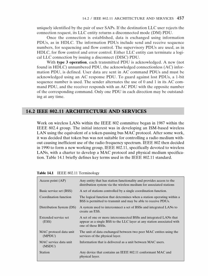
Work on wireless LANs within the IEEE 802 committee began in 1987 within theIEEE 802.4 group. The initial interest was in developing an ISM-based wirelessLAN using the equivalent of a token-passing bus MAC protocol. After some work,it was decided that token bus was not suitable for controlling a radio medium with-out causing inefficient use of the radio frequency spectrum. IEEE 802 then decidedin 1990 to form a new working group, IEEE 802.11, specifically devoted to wirelessLANs, with a charter to develop a MAC protocol and physical medium specifica-tion. Table 14.1 briefly defines key terms used in the IEEE 802.11 standard.
Table 14.1 IEEE 802.11 Terminology
Access point (AP) Any entity that has station functionality and provides access to thedistribution system via the wireless medium for associated stations
Basic service set (BSS) A set of stations controlled by a single coordination function.
Coordination function The logical function that determines when a station operating within aBSS is permitted to transmit and may be able to receive PDUs.
Distribution System (DS) A system used to interconnect a set of BSSs and integrated LANs tocreate an ESS.
Extended service set A set of one or more interconnected BSSs and integrated LANs that(ESS) appear as a single BSS to the LLC layer at any station associated with
one of these BSSs.
MAC protocol data unit The unit of data exchanged between two peer MAC entites using the (MPDU) services of the physical layer.
MAC service data unit Information that is delivered as a unit between MAC users.(MSDU)
Station Any device that contains an IEEE 802.11 conformant MAC andphysical layer.
14 StallingsIII 5/31/01 9:03 PM Page 457
458 CHAPTER 14 / IEEE 802.11 WIRELESS LAN STANDARD
Basicservice set
STA2
STA3
STA = station
STA4 Basicservice set
Extendedservice set
STA6 STA7
Distribution system
IEEE 802.x LAN
STA1
AP
STA5
AP
Portal
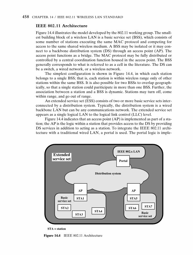
Figure 14.4 IEEE 802.11 Architecture
IEEE 802.11 Architecture
Figure 14.4 illustrates the model developed by the 802.11 working group. The small-est building block of a wireless LAN is a basic service set (BSS), which consists ofsome number of stations executing the same MAC protocol and competing foraccess to the same shared wireless medium. A BSS may be isolated or it may con-nect to a backbone distribution system (DS) through an access point (AP). Theaccess point functions as a bridge. The MAC protocol may be fully distributed orcontrolled by a central coordination function housed in the access point. The BSSgenerally corresponds to what is referred to as a cell in the literature. The DS canbe a switch, a wired network, or a wireless network.
The simplest configuration is shown in Figure 14.4, in which each stationbelongs to a single BSS; that is, each station is within wireless range only of otherstations within the same BSS. It is also possible for two BSSs to overlap geograph-ically, so that a single station could pariticipate in more than one BSS. Further, theassociation between a station and a BSS is dynamic. Stations may turn off, comewithin range, and go out of range.
An extended service set (ESS) consists of two or more basic service sets inter-connected by a distribution system. Typically, the distribution system is a wiredbackbone LAN but can be any communications network. The extended service setappears as a single logical LAN to the logical link control (LLC) level.
Figure 14.4 indicates that an access point (AP) is implemented as part of a sta-tion; the AP is the logic within a station that provides access to the DS by providingDS services in addition to acting as a station. To integrate the IEEE 802.11 archi-tecture with a traditional wired LAN, a portal is used. The portal logic is imple-
14 StallingsIII 5/31/01 9:03 PM Page 458
14.2 / IEEE 802.11 ARCHITECTURE AND SERVICES 459
Service Provider Used to support
Association Distribution system MSDU delivery
Authentication Station LAN access and security
Deauthentication Station LAN access and security
Dissassociation Distribution system MSDU delivery
Distribution Distribution system MSDU delivery
Integration Distribution system MSDU delivery
MSDU delivery Station MSDU delivery
Privacy Station LAN access and security
Reassociation Distribution system MSDU delivery
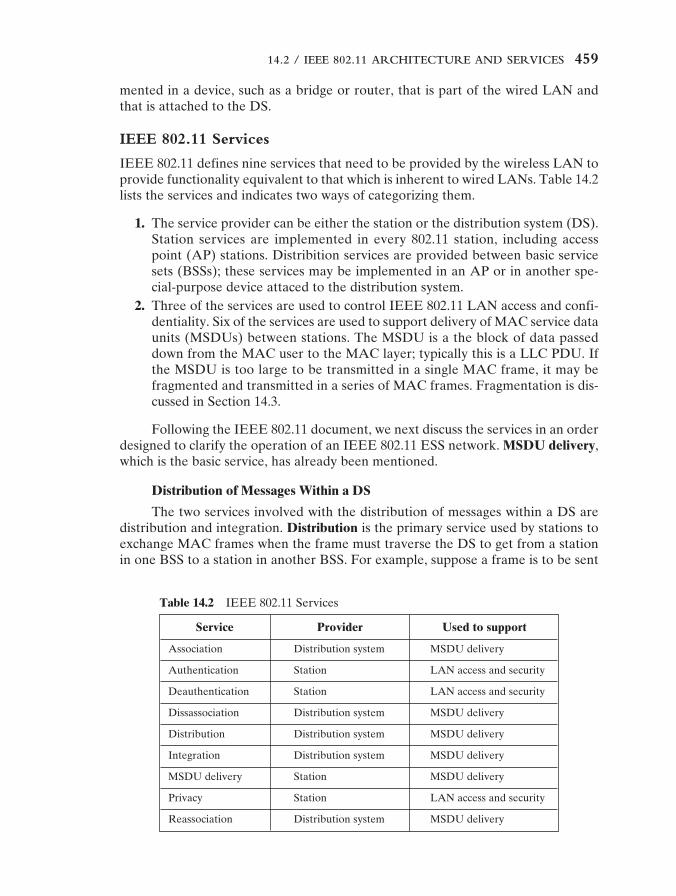
Table 14.2 IEEE 802.11 Services
mented in a device, such as a bridge or router, that is part of the wired LAN andthat is attached to the DS.
IEEE 802.11 Services
IEEE 802.11 defines nine services that need to be provided by the wireless LAN toprovide functionality equivalent to that which is inherent to wired LANs. Table 14.2lists the services and indicates two ways of categorizing them.
1. The service provider can be either the station or the distribution system (DS).Station services are implemented in every 802.11 station, including accesspoint (AP) stations. Distribition services are provided between basic servicesets (BSSs); these services may be implemented in an AP or in another spe-cial-purpose device attaced to the distribution system.
2. Three of the services are used to control IEEE 802.11 LAN access and confi-dentiality. Six of the services are used to support delivery of MAC service dataunits (MSDUs) between stations. The MSDU is a the block of data passeddown from the MAC user to the MAC layer; typically this is a LLC PDU. Ifthe MSDU is too large to be transmitted in a single MAC frame, it may befragmented and transmitted in a series of MAC frames. Fragmentation is dis-cussed in Section 14.3.
Following the IEEE 802.11 document, we next discuss the services in an orderdesigned to clarify the operation of an IEEE 802.11 ESS network. MSDU delivery,which is the basic service, has already been mentioned.
Distribution of Messages Within a DS
The two services involved with the distribution of messages within a DS aredistribution and integration. Distribution is the primary service used by stations toexchange MAC frames when the frame must traverse the DS to get from a stationin one BSS to a station in another BSS. For example, suppose a frame is to be sent
14 StallingsIII 5/31/01 9:03 PM Page 459
460 CHAPTER 14 / IEEE 802.11 WIRELESS LAN STANDARD
from station 2 (STA 2) to STA 7 in Figure 14.4. The frame is sent from STA 2 toSTA 1, which is the AP for this BSS. The AP gives the frame to the DS, which hasthe job of directing the frame to the AP associated with STA 5 in the target BSS.STA 5 receives the frame and forwards it to STA 7. How the message is transportedthrough the DS is beyond the scope of the IEEE 802.11 standard.
If the two stations that are communicating are within the same BSS, then thedistribution service logically goes through the single AP of that BSS.
The integration service enables transfer of data between a station on an IEEE802.11 LAN and a station on an integrated IEEE 802.x LAN. The term integratedrefers to a wired LAN that is physically connected to the DS and whose stations maybe logically connected to an IEEE 802.11 LAN via the integration service. The inte-gration service takes care of any address translation and media conversion logicrequired for the exchange of data.
Association-Related Services
The primary purpose of the MAC layer is to transfer MSDUs between MACentities; this purpose is fulfilled by the distribution service. For that service to func-tion, it requires information about stations within the ESS that is provided by theassociation-related services. Before the distribution service can deliver data to oraccept data from a station, that station must be associated. Before looking at theconcept of association, we need to describe the concept of mobility. The standarddefines three transition types of based on mobility:
• No transition: A station of this type is either stationary or moves only withinthe direct communication range of the communicating stations of a single BSS.
• BSS transition: This is defined as a station movement from one BSS toanother BSS within the same ESS. In this case, delivery of data to the stationrequires that the addressing capability be able to recognize the new locationof the station.
• ESS transition: This is defined as a station movement from a BSS in one ESSto a BSS within another ESS. This case is supported only in the sense that thestation can move. Maintenance of upper-layer connections supported by802.11 cannot be guaranteed. In fact, disruption of service is likely to occur.
To deliver a message within a DS, the distribution service needs to knowwhere the destination station is located. Specifically, the DS needs to know the iden-tity of the AP to which the message should be delivered in order for that messageto reach the destination station. To meet this requirement, a station must maintainan association with the AP within its current BSS. Three services relate to thisrequirement:
• Association: Establishes an initial association between a station and an AP.Before a station can transmit or receive frames on a wireless LAN, its identityand address must be known. For this purpose, a station must establish an asso-ciation with an AP within a particular BSS. The AP can then communicate thisinformation to other APs within the ESS to facilitate routing and delivery ofaddressed frames.
14 StallingsIII 5/31/01 9:03 PM Page 460
14.2 / IEEE 802.11 ARCHITECTURE AND SERVICES 461
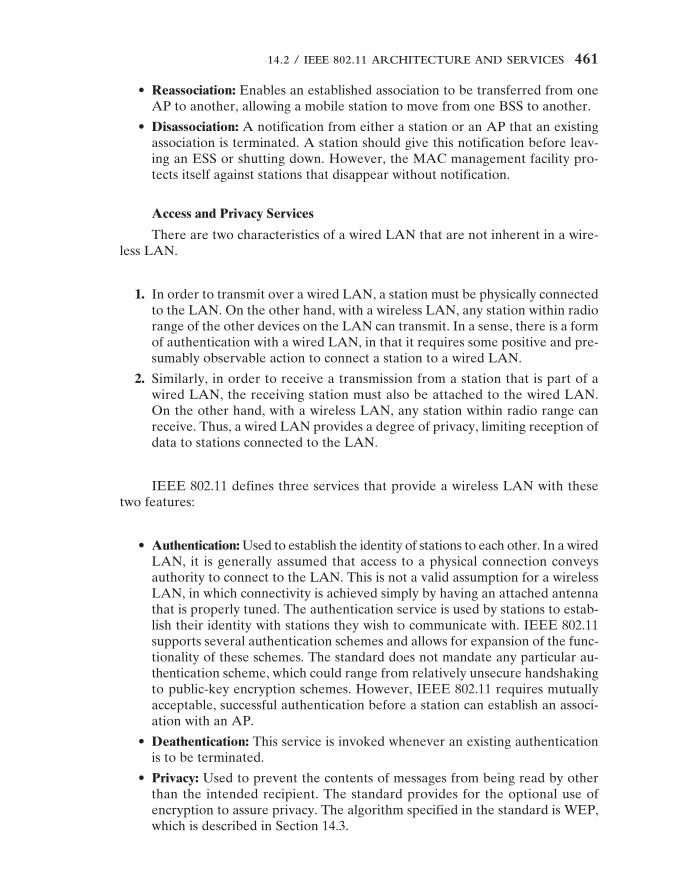
• Reassociation: Enables an established association to be transferred from oneAP to another, allowing a mobile station to move from one BSS to another.
• Disassociation: A notification from either a station or an AP that an existingassociation is terminated. A station should give this notification before leav-ing an ESS or shutting down. However, the MAC management facility pro-tects itself against stations that disappear without notification.
Access and Privacy Services
There are two characteristics of a wired LAN that are not inherent in a wire-less LAN.
1. In order to transmit over a wired LAN, a station must be physically connectedto the LAN. On the other hand, with a wireless LAN, any station within radiorange of the other devices on the LAN can transmit. In a sense, there is a formof authentication with a wired LAN, in that it requires some positive and pre-sumably observable action to connect a station to a wired LAN.
2. Similarly, in order to receive a transmission from a station that is part of awired LAN, the receiving station must also be attached to the wired LAN.On the other hand, with a wireless LAN, any station within radio range canreceive. Thus, a wired LAN provides a degree of privacy, limiting reception ofdata to stations connected to the LAN.
IEEE 802.11 defines three services that provide a wireless LAN with thesetwo features:
• Authentication: Used to establish the identity of stations to each other. In a wiredLAN, it is generally assumed that access to a physical connection conveysauthority to connect to the LAN. This is not a valid assumption for a wirelessLAN, in which connectivity is achieved simply by having an attached antennathat is properly tuned. The authentication service is used by stations to estab-lish their identity with stations they wish to communicate with. IEEE 802.11supports several authentication schemes and allows for expansion of the func-tionality of these schemes. The standard does not mandate any particular au-thentication scheme, which could range from relatively unsecure handshakingto public-key encryption schemes. However, IEEE 802.11 requires mutuallyacceptable, successful authentication before a station can establish an associ-ation with an AP.
• Deathentication: This service is invoked whenever an existing authenticationis to be terminated.
• Privacy: Used to prevent the contents of messages from being read by otherthan the intended recipient. The standard provides for the optional use ofencryption to assure privacy. The algorithm specified in the standard is WEP,which is described in Section 14.3.
14 StallingsIII 5/31/01 9:03 PM Page 461
462 CHAPTER 14 / IEEE 802.11 WIRELESS LAN STANDARD
14.3 IEEE 802.11 MEDIUM ACCESS CONTROL
The IEEE 802.11 MAC layer covers three functional areas: reliable data delivery,access control, and security. We look at each of these in turn.
Reliable Data Delivery
As with any wireless network, a wireless LAN using the IEEE 802.11 physical andMAC layers is subject to considerable unreliability. Noise, interference, and otherpropagation effects result in the loss of a significant number of frames. Even witherror-correction codes, a number of MAC frames may not successfully be received.This situation can be dealt with by reliability mechanisms at a higher layer, such asTCP. However, timers used for retransmission at higher layers are typically on theorder of seconds. It is therefore more efficient to deal with errors at the MAC level.For this purpose, IEEE 802.11 includes a frame exchange protocol. When a stationreceives a data frame from another station it returns an acknowledgment (ACK)frame to the source station. This exchange is treated as an atomic unit, not to beinterrupted by a transmission from any other station. If the source does not receivean ACK within a short period of time, either because its data frame was damagedor because the returning ACK was damaged, the source retransmits the frame.
Thus, the basic data transfer mechanism in IEEE 802.11 involves an exchangeof two frames. To further enhance reliability, a four-frame exchange may be used.In this scheme, a source first issues a request to send (RTS) frame to the destina-tion. The destination then responds with a clear to send (CTS). After receiving theCTS, the source transmits the data frame, and the destination responds with anACK. The RTS alerts all stations that are within reception range of the source thatan exchange is under way; these stations refrain from transmission in order to avoida collision between two frames transmitted at the same time. Similarly, the CTSalerts all stations that are within reception range of the destination that an exchangeis under way. The RTS/CTS portion of the exchange is a required function of theMAC but may be disabled.
Access Control
The 802.11 working group considered two types of proposals for a MAC algorithm:distributed access protocols, which, like Ethernet, distribute the decision to trans-mit over all the nodes using a carrier-sense mechanism; and centralized access pro-tocols, which involve regulation of transmission by a centralized decision maker. Adistributed access protocol makes sense for an ad hoc network of peer workstationsand may also be attractive in other wireless LAN configurations that consist pri-marily of bursty traffic. A centralized access protocol is natural for configurationsin which a number of wireless stations are interconnected with each other and somesort of base station that attaches to a backbone wired LAN; it is especially useful ifsome of the data is time sensitive or high priority.
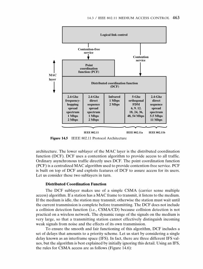
The end result for 802.11 is a MAC algorithm called DFWMAC (distributedfoundation wireless MAC) that provides a distributed access control mechanismwith an optional centralized control built on top of that. Figure 14.5 illustrates the
14 StallingsIII 5/31/01 9:03 PM Page 462
14.3 / IEEE 802.11 MEDIUM ACCESS CONTROL 463
Pointcoordination
function (PCF)
Contention-freeservice
Contentionservice
MAClayer
Distributed coordination function
Logical link control
(DCF)
2.4-Ghzfrequency-
hoppingspread
spectrum1 Mbps2 Mbps
2.4-Ghzdirect
sequencespread
spectrum1 Mbps2 Mbps
2.4-Ghzdirect
sequencespread
spectrum5.5 Mbps11 Mbps
Infrared1 Mbps2 Mbps
IEEE 802.11 IEEE 802.11a IEEE 802.11b
5-Ghzorthogonal
FDM6, 9. 12.
18, 24, 36,48, 54 Mbps
Figure 14.5 IEEE 802.11 Protocol Architecture
architecture. The lower sublayer of the MAC layer is the distributed coordinationfunction (DCF). DCF uses a contention algorithm to provide access to all traffic.Ordinary asynchronous traffic directly uses DCF. The point coordination function(PCF) is a centralized MAC algorithm used to provide contention-free service. PCFis built on top of DCF and exploits features of DCF to assure access for its users.Let us consider these two sublayers in turn.
Distributed Coordination Function
The DCF sublayer makes use of a simple CSMA (carrier sense multipleaccess) algorithm. If a station has a MAC frame to transmit, it listens to the medium.If the medium is idle, the station may transmit; otherwise the station must wait untilthe current transmission is complete before transmitting. The DCF does not includea collision detection function (i.e., CSMA/CD) because collision detection is notpractical on a wireless network. The dynamic range of the signals on the medium isvery large, so that a transmitting station cannot effectively distinguish incomingweak signals from noise and the effects of its own transmission.
To ensure the smooth and fair functioning of this algorithm, DCF includes aset of delays that amounts to a priority scheme. Let us start by considering a singledelay known as an interframe space (IFS). In fact, there are three different IFS val-ues, but the algorithm is best explained by initially ignoring this detail. Using an IFS,the rules for CSMA access are as follows (Figure 14.6):
14 StallingsIII 5/31/01 9:03 PM Page 463
464 CHAPTER 14 / IEEE 802.11 WIRELESS LAN STANDARD
Wait for frameto transmit
Wait until currenttransmission ends
Exponential backoffwhile medium idle
Wait IFS
No
Yes
Yes
Yes
No
No
Wait IFSTransmit frame
Transmit frame
Mediumidle?
Stillidle?
Stillidle?
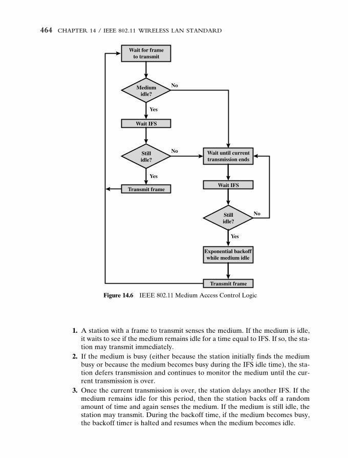
Figure 14.6 IEEE 802.11 Medium Access Control Logic
1. A station with a frame to transmit senses the medium. If the medium is idle,it waits to see if the medium remains idle for a time equal to IFS. If so, the sta-tion may transmit immediately.
2. If the medium is busy (either because the station initially finds the mediumbusy or because the medium becomes busy during the IFS idle time), the sta-tion defers transmission and continues to monitor the medium until the cur-rent transmission is over.
3. Once the current transmission is over, the station delays another IFS. If themedium remains idle for this period, then the station backs off a randomamount of time and again senses the medium. If the medium is still idle, thestation may transmit. During the backoff time, if the medium becomes busy,the backoff timer is halted and resumes when the medium becomes idle.
14 StallingsIII 5/31/01 9:03 PM Page 464
14.3 / IEEE 802.11 MEDIUM ACCESS CONTROL 465
DIFS
Immediate accesswhen medium is free
longer than DIFS
SIFS
PIFS
DIFS
Busy medium Next frameBackoff window
Contention window
Defer access
Slot time
Select slot using binary exponential backoff
(a) Basic access method
Time
PCF (optional)
Contention-freeperiod
Variable length(per superframe)
Busy medium PCF (optional)DCF
Contention period
Superframe (fixed nominal length)
Superframe (fixed nominal length)
Foreshortened actual superframe period
PCFdefers
CF-Burst;asynchronoustraffic defers
(b) PCF superframe construction
Figure 14.7 IEEE 802.11 MAC Timing
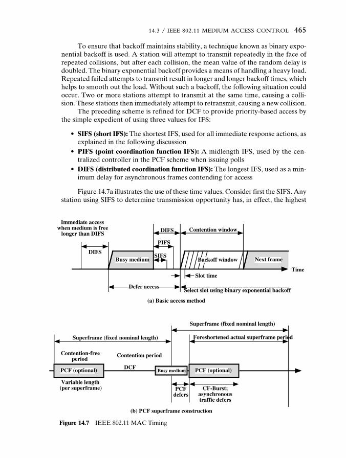
To ensure that backoff maintains stability, a technique known as binary expo-nential backoff is used. A station will attempt to transmit repeatedly in the face ofrepeated collisions, but after each collision, the mean value of the random delay isdoubled. The binary exponential backoff provides a means of handling a heavy load.Repeated failed attempts to transmit result in longer and longer backoff times, whichhelps to smooth out the load. Without such a backoff, the following situation couldoccur. Two or more stations attempt to transmit at the same time, causing a colli-sion. These stations then immediately attempt to retransmit, causing a new collision.
The preceding scheme is refined for DCF to provide priority-based access bythe simple expedient of using three values for IFS:
• SIFS (short IFS): The shortest IFS, used for all immediate response actions, asexplained in the following discussion
• PIFS (point coordination function IFS): A midlength IFS, used by the cen-tralized controller in the PCF scheme when issuing polls
• DIFS (distributed coordination function IFS): The longest IFS, used as a min-imum delay for asynchronous frames contending for access
Figure 14.7a illustrates the use of these time values. Consider first the SIFS. Anystation using SIFS to determine transmission opportunity has, in effect, the highest
14 StallingsIII 5/31/01 9:03 PM Page 465
466 CHAPTER 14 / IEEE 802.11 WIRELESS LAN STANDARD
priority, because it will always gain access in preference to a station waiting an amountof time equal to PIFS or DIFS. The SIFS is used in the following circumstances:
• Acknowledgment (ACK): When a station receives a frame addressed only toitself (not multicast or broadcast) it responds with an ACK frame after wait-ing only for an SIFS gap. This has two desirable effects. First, because colli-sion detection is not used, the likelihood of collisions is greater than withCSMA/CD, and the MAC-level ACK provides for efficient collision recovery.Second, the SIFS can be used to provide efficient delivery of an LLC protocoldata unit (PDU) that requires multiple MAC frames. In this case, the follow-ing scenario occurs. A station with a multiframe LLC PDU to transmit sendsout the MAC frames one at a time. Each frame is acknowledged after SIFS bythe recipient. When the source receives an ACK, it immediately (after SIFS)sends the next frame in the sequence. The result is that once a station has con-tended for the channel, it will maintain control of the channel until it has sentall of the fragments of an LLC PDU.
• Clear to Send (CTS): A station can ensure that its data frame will get throughby first issuing a small Request to Send (RTS) frame. The station to which thisframe is addressed should immediately respond with a CTS frame if it is readyto receive. All other stations receive the RTS and defer using the medium.
• Poll response: This is explained in the following discussion of PCF.
The next longest IFS interval is the PIFS. This is used by the centralized con-troller in issuing polls and takes precedence over normal contention traffic. How-ever, those frames transmitted using SIFS have precedence over a PCF poll.
Finally, the DIFS interval is used for all ordinary asynchronous traffic.
Point Coordination Function
PCF is an alternative access method implemented on top of the DCF. Theoperation consists of polling by the centralized polling master (point coordinator).The point coordinator makes use of PIFS when issuing polls. Because PIFS issmaller than DIFS, the point coordinator can seize the medium and lock out allasynchronous traffic while it issues polls and receives responses.
As an extreme, consider the following possible scenario. A wireless networkis configured so that a number of stations with time-sensitive traffic are controlledby the point coordinator while remaining traffic contends for access using CSMA.The point coordinator could issue polls in a round-robin fashion to all stations con-figured for polling. When a poll is issued, the polled station may respond usingSIFS. If the point coordinator receives a response, it issues another poll using PIFS.If no response is received during the expected turnaround time, the coordinatorissues a poll.
If the discipline of the preceding paragraph were implemented, the point coor-dinator would lock out all asynchronous traffic by repeatedly issuing polls. To pre-vent this, an interval known as the superframe is defined. During the first part ofthis interval, the point coordinator issues polls in a round-robin fashion to all sta-tions configured for polling. The point coordinator then idles for the remainder of thesuperframe, allowing a contention period for asynchronous access.
14 StallingsIII 5/31/01 9:03 PM Page 466
14.3 / IEEE 802.11 MEDIUM ACCESS CONTROL 467
FC
octets
bits 2 2 4 1 1 1 1 1 1 1 1
2 2 6 6 6 2 6 0 to 2312 4
Protocolversion Type Subtype
ToDS
FromDS MF RT PM MD W O
FC � Frame controlD/I � Duration/Connection IDSC � Sequence control
DS � Distribution systemMF � More fragmentsRT � RetryPM � Power management
MD � More dataW � Wired equivalent privacy bitO � Order
D/I Address Address Address
(a) MAC frame
(b) Frame control field
Address Frame body CRCSC
Figure 14.8 IEEE 802.11 MAC Frame Format
Figure 14.7b illustrates the use of the superframe. At the beginning of a super-frame, the point coordinator may optionally seize control and issues polls for a giveperiod of time. This interval varies because of the variable frame size issued byresponding stations. The remainder of the superframe is available for contention-based access. At the end of the superframe interval, the point coordinator contendsfor access to the medium using PIFS. If the medium is idle, the point coordinatorgains immediate access and a full superframe period follows. However, the mediummay be busy at the end of a superframe. In this case, the point coordinator must waituntil the medium is idle to gain access; this results in a foreshortened superframeperiod for the next cycle.
MAC Frame
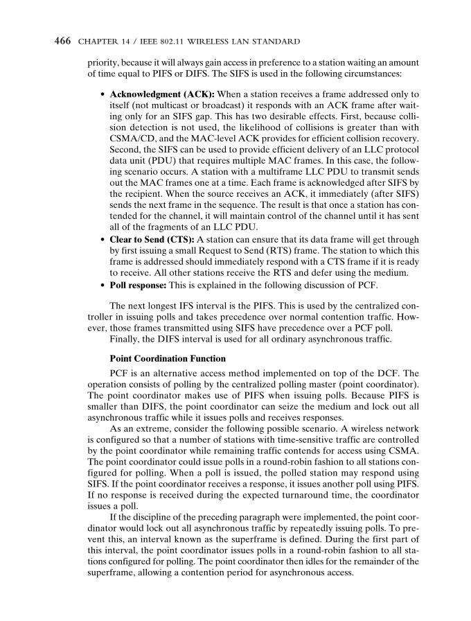
Figure 14.8a shows the 802.11 frame format. This general format is used for all dataand control frames, but not all fields are used in all contexts. The fields are as follows:
• Frame control: Indicates the type of frame and provides control information,as explained presently.
• Duration/connection ID: If used as a duration field, indicates the time (inmicroseconds) the channel will be allocated for successful transmission of aMAC frame. In some control frames, this field contains an association, or con-nection, identifier.
14 StallingsIII 5/31/01 9:03 PM Page 467
468 CHAPTER 14 / IEEE 802.11 WIRELESS LAN STANDARD
• Addresses: The number and meaning of the address fields depend on con-text. Address types include source, destination, transmitting station, andreceiving station.
• Sequence control: Contains a 4-bit fragment number subfield, used for frag-mentation and reassembly, and a 12-bit sequence number used to numberframes sent between a given transmitter and receiver.
• Frame body: Contains an MSDU or a fragment of an MSDU. The MSDU is aLLC protocol data unit or MAC control information.
• Frame check sequence: A 32-bit cyclic redundancy check.
The frame control field, shown in Figure 14.8b, consists of the following fields:
• Protocol version: 802.11 version, currently version 0.• Type: Identifies the frame as control, management, or data.• Subtype: Further identifies the function of frame. Table 14.3 Defines the valid
combinations of type and subtype.• To DS: The MAC coordination sets this bit to 1 in a frame destined to the dis-
tribution system.• From DS: The MAC coordination sets this bit to 1 in a frame leaving the dis-
tribution system.• More fragments: Set to 1 if more fragments follow this one.• Retry: Set to 1 if this is a retransmission of a previous frame.• Power management: Set to 1 if the transmitting station is in a sleep mode.• More data: Indicates that a station has additional data to send. Each block of
data may be sent as one frame or a group of fragments in multiple frames.• WEP: Set to 1 if the optional wired equivalent protocol is implemented. WEP
is used in the exchange of encryption keys for secure data exchange.• Order: Set to 1 in any data frame sent using the Strictly Ordered service, which
tells the receiving station that frames must be processed in order.
We now look at the various MAC frame types.
Control Frames
Control frames assist in the reliable delivery of data frames. There are six con-trol frame subtypes:
• Power save-poll (PS-Poll): This frame is sent by any station to the station thatincludes the AP (access point). Its purpose is to request that the AP transmita frame that has been buffered for this station while the station was in power-saving mode.
• Request to send (RTS): This is the first frame in the four-way frame exchangediscussed under the subsection on reliable data delivery at the beginning ofSection 14.3. The station sending this message is alerting a potential destina-tion, and all other stations within reception range, that it intends to send a dataframe to that destination.
14 StallingsIII 5/31/01 9:03 PM Page 468
14.3 / IEEE 802.11 MEDIUM ACCESS CONTROL 469
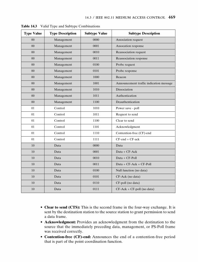
Type Value Type Description Subtype Value Subtype Description
00 Management 0000 Association request
00 Management 0001 Assocation response
00 Management 0010 Reassociation request
00 Management 0011 Reassociation response
00 Management 0100 Probe request
00 Management 0101 Probe response
00 Management 1000 Beacon
00 Management 1001 Announcement traffic indication message
00 Management 1010 Dissociation
00 Management 1011 Authentication
00 Management 1100 Deauthentication
01 Control 1010 Power save - poll
01 Control 1011 Request to send
01 Control 1100 Clear to send
01 Control 1101 Acknowledgment
01 Control 1110 Contention-free (CF)-end
01 Control 1111 CF-end + CF-ack
10 Data 0000 Data
10 Data 0001 Data + CF-Ack
10 Data 0010 Data + CF-Poll
10 Data 0011 Data + CF-Ack + CF-Poll
10 Data 0100 Null function (no data)
10 Data 0101 CF-Ack (no data)
10 Data 0110 CF-poll (no data)
10 Data 0111 CF-Ack + CF-poll (no data)
Table 14.3 Valid Type and Subtype Combinations
• Clear to send (CTS): This is the second frame in the four-way exchange. It issent by the destination station to the source station to grant permission to senda data frame.
• Acknowledgment: Provides an acknowledgment from the destination to thesource that the immediately preceding data, management, or PS-Poll framewas received correctly.
• Contention-free (CF)-end: Announces the end of a contention-free periodthat is part of the point coordination function.
14 StallingsIII 5/31/01 9:03 PM Page 469
470 CHAPTER 14 / IEEE 802.11 WIRELESS LAN STANDARD
• CF-end � CF-ack: Acknowledges the CF-end. This frame ends the con-tention-free period and releases stations from the restrictions associated withthat period.
Data Frames
There are eight data frame subtypes, organized into two groups. The first foursubtypes define frames that carry upper-level data from the source station to thedestination station. The four data-carrying frames are as follows:
• Data: This is the simplest data frame. It may be used in both a contentionperiod and a contention-free period.
• Data � CF-Ack: May only be sent during a contention-free period. In addi-tion to carrying data, this frame acknowledges previously received data.
• Data � CF-Poll: Used by a point coordinator to deliver data to a mobile sta-tion and also to request that the mobile station send a data frame that it mayhave buffered.
• Data � CF-Ack � CF-Poll: Combines the functions of the Data � CF-Ackand Data � CF-Poll into a single frame.
The remaining four subtypes of data frames do not in fact carry any user data.The Null Function data frame carries no data, polls, or acknowledgments. It is usedonly to carry the power management bit in the frame control field to the AP, to indi-cate that the station is changing to a low-power operating state. The remaining threeframes (CF-Ack, CF-Poll, CF-Ack � CF-Poll) have the same functionality as thecorresponding data frame subtypes in the preceding list (Data � CF-Ack, Data �CF-Poll, Data � CF-Ack � CF-Poll) but without the data.
Management Frames
Management frames are used to manage communications between stationsand APs. The following subtypes are included:
• Association request: Sent by a station to an AP to request an association withthis BSS. This frame includes capability information, such as whether encryp-tion is to be used and whether this station is pollable.
• Association response: Returned by the AP to the station to indicate whetherit is accepting this association request.
• Reassociation request: Sent by a station when it moves from one BSS toanother and needs to make an association with the AP in the new BSS. Thestation uses reassociation rather than simply association so that the new APknows to negotiate with the old AP for the forwarding of data frames.
• Reassociation response: Returned by the AP to the station to indicate whetherit is accepting this reassociation request.
• Probe request: Used by a station to obtain information from another stationor AP. This frame is used to locate an IEEE 802.11 BSS.
14 StallingsIII 5/31/01 9:03 PM Page 470
14.3 / IEEE 802.11 MEDIUM ACCESS CONTROL 471
• Probe response: Response to a probe request.• Beacon: Transmitted periodically to allow mobile stations to locate and iden-
tify a BSS.• Announcement traffic indication message: Sent by a mobile station to alert
other mobile stations that may have been in low power mode that this stationhas frames buffered and waiting to be delivered to the station addressed inthis frame.
• Dissociation: Used by a station to terminate an association.• Authentication: Multiple authentication frames are used in an exchange to
authenticate one station to another, as described subsequently. • Deauthentication: Sent by a station to another station or AP to indicate that
it is terminating secure communications.
Security Considerations
IEEE 802.11 provides both privacy and authentication mechanisms.
The Wired Equivalent Privacy Algorithm
With a wireless LAN, eavesdropping is a major concern because of the easeof capturing a transmission. IEEE 802.11 incorporates WEP to provide a modestlevel of security. To provide privacy, as well as data integrity, WEP uses an encryp-tion algorithm based on the RC4 encryption algorithm.
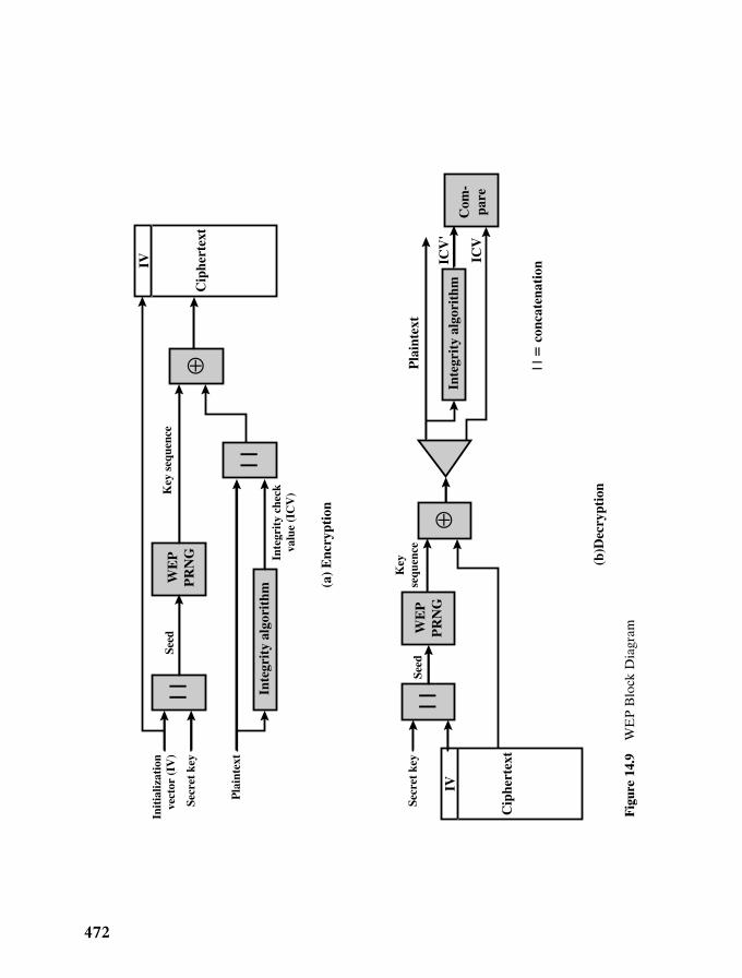
Figure 14.9a shows the encryption process. The integrity algorithm is simplythe 32-bit CRC that is appended to the end of the MAC frame (Figure 14.8a). Forthe encryption process, a 40-bit secret key is shared by the two participants in theexchange. An initialization vector (IV) is concatenated to the secret key. The result-ing block forms the seed that is input to the pseudorandom number generator(PRNG) defined in RC4. The PRNG generates a bit sequence of the same lengthas the MAC frame plus its CRC. A bit-by-bit exclusive-OR between the MACframe and the PRNG sequence produces the ciphertext. The IV is attached to theciphertext and the resulting block is transmitted. The IV is changed periodically (asoften as every transmission). Every time the IV is changed, the PRNG sequence ischanged, which complicates the task of an eavesdropper.
At the receiving end (Figure 14.9b), the receiver retrieves the IV from thedata block and concatenates this with the shared secret key to generate the samekey sequence used by the sender. This key sequence is then XORed with the incom-ing block to recover the plaintext. This technique makes use of the following prop-erty of XOR:
A ⊕ B ⊕ B � A
Thus, if we take the plaintext, XOR it with the key sequence, and then XOR theresult with the key sequence, we get back the plaintext. Finally, the receiver com-pares the incoming CRC with the CRC calculated at the receiver to validate integrity.
14 StallingsIII 5/31/01 9:03 PM Page 471
472
| | | |
| |
⊕W
EP
PR
NG
(a)
Enc
rypt
ion
(b)D
ecry
ptio
n
Inte
grit
y ch
eck
valu
e (I
CV
)Key
seq
uenc
e
Pla
inte
xt
Seed
Secr
et k
ey
Init
ializ
atio
nve
ctor
(IV
)
IV
Cip
hert
ext
IV
Cip
hert
ext
Pla
inte
xt
ICV
'
ICV
Secr
et k
ey
Inte
grit
y al
gori
thm
Inte
grit
y al
gori
thm
WE
PP
RN
G
Com
-pa
re
Seed
⊕
Key
sequ
ence
| | �
con
cate
nati
on
Fig
ure
14.9
WE
P B
lock
Dia
gram
14 StallingsIII 5/31/01 9:03 PM Page 472
14.4 / IEEE 802.11 PHYSICAL LAYER 473
Authentication
IEEE 802.11 provides two types of authentication: open system and sharedkey. Open system authentication simply provides a way for two parties to agree toexchange data and provides no security benefits. In open system authentication,one party sends a MAC control frame, known as an authentication frame, to the otherparty. The frame indicates that this is an open system authentication type. Theother party responds with its own authentication frame and the process is complete.Thus, open system authentication consists simply of the exchange of the identitiesbetween the parties.
Shared key authentication requires that the two parties share a secret key notshared by any other party. This key is used to assure that both sides are authenti-cated to each other. The procedure for authentication between two parties, A andB, is as follows:
1. A sends a MAC authentication frame with an authentication algorithm iden-tification of “Shared Key” and with a station identifier that identifies the send-ing station.
2. B responds with an authentication frame that includes a 128-octet challengetext. The challenge text is generate using the WEP PRNG. The key and IVused in generating this challenge text are unimportant because they do notplay a role in the remainder of the procedure.
3. A transmits an authentication frame that includes the challenge text justreceived from B. The entire frame is encrypted using WEP.
4. B receives the encrypted frame and decrypts it using WEP and the secret keyshared with A. If decryption is successful (matching CRCs), then B comparesthe incoming challenge text with the challenge text that it sent in the secondmessage. B then sends an authentication message to A with a status code indi-cating success or failure.
14.4 IEEE 802.11 PHYSICAL LAYER
The physical layer for IEEE 802.11 has been issued in three stages; the first part wasissued in 1997 and the remaining two parts in 1999. The first part, simply calledIEEE 802.11, includes the MAC layer and three physical layer specifications, two inthe 2.4-GHz band and one in the infrared, all operating at 1 and 2 Mbps. IEEE802.11a operates in the 5-GHz band at data rates up to 54 Mbps. IEEE 802.11boperates in the 2.4-Ghz band at 5.5 and 11 Mbps. We look at each of these in turn.
Original IEEE 802.11 Physical Layer
Three physical media are defined in the original 802.11 standard:
• Direct-sequence spread spectrum operating in the 2.4-GHz ISM band, at datarates of 1 Mbps and 2 Mbps
14 StallingsIII 5/31/01 9:03 PM Page 473
474 CHAPTER 14 / IEEE 802.11 WIRELESS LAN STANDARD
Chipping code Data rate length Modulation Symbol rate Bits/symbol
1 Mbps 11 (Barker sequence) DBPSK 1 Msps 1
2 Mbps 11 (Barker sequence) DQPSK 1 Msps 2
5.5 Mbps 8 (CCK) DBPSK 1.375 Msps 4
11 Mbps 8 (CCK) DQPSK 1.375 Msps 8
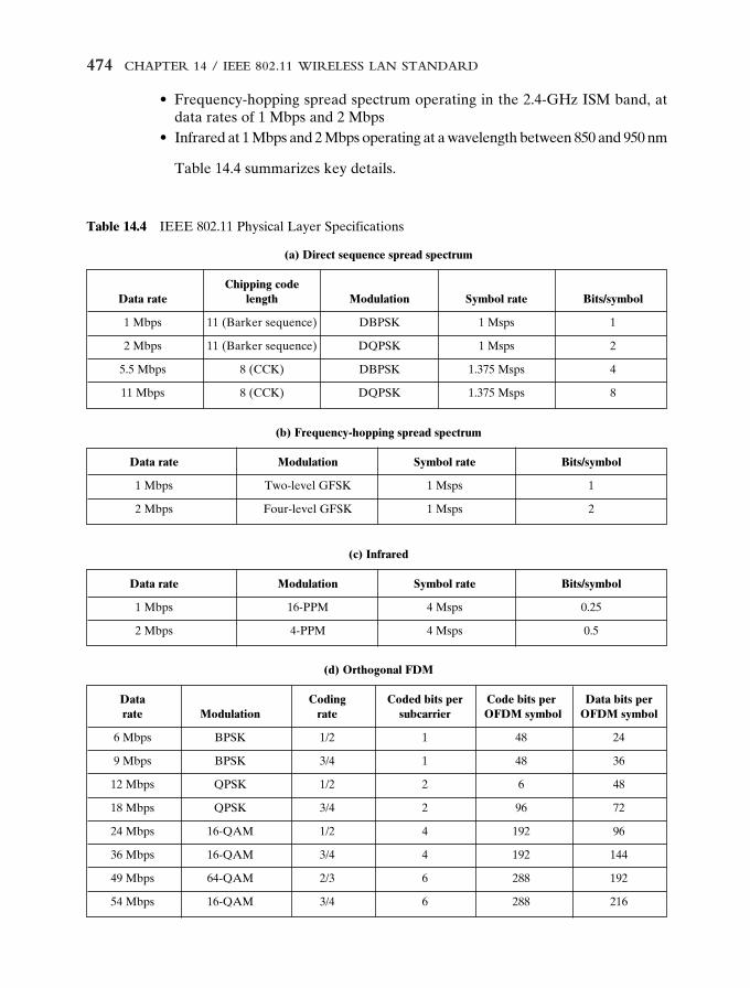
Table 14.4 IEEE 802.11 Physical Layer Specifications
(a) Direct sequence spread spectrum
Data Coding Coded bits per Code bits per Data bits per rate Modulation rate subcarrier OFDM symbol OFDM symbol
6 Mbps BPSK 1/2 1 48 24
9 Mbps BPSK 3/4 1 48 36
12 Mbps QPSK 1/2 2 6 48
18 Mbps QPSK 3/4 2 96 72
24 Mbps 16-QAM 1/2 4 192 96
36 Mbps 16-QAM 3/4 4 192 144
49 Mbps 64-QAM 2/3 6 288 192
54 Mbps 16-QAM 3/4 6 288 216
(d) Orthogonal FDM
Data rate Modulation Symbol rate Bits/symbol
1 Mbps Two-level GFSK 1 Msps 1
2 Mbps Four-level GFSK 1 Msps 2
(b) Frequency-hopping spread spectrum
Data rate Modulation Symbol rate Bits/symbol
1 Mbps 16-PPM 4 Msps 0.25
2 Mbps 4-PPM 4 Msps 0.5
(c) Infrared
• Frequency-hopping spread spectrum operating in the 2.4-GHz ISM band, atdata rates of 1 Mbps and 2 Mbps
• Infrared at 1 Mbps and 2 Mbps operating at a wavelength between 850 and 950 nm
Table 14.4 summarizes key details.
14 StallingsIII 5/31/01 9:03 PM Page 474
14.4 / IEEE 802.11 PHYSICAL LAYER 475
Direct-Sequence Spread Spectrum
Up to seven channels, each with a data rate of 1 Mbps or 2 Mbps, can be usedin the DS-SS system. The number of channels available depends on the bandwidthallocated by the various national regulatory agencies. This ranges from 13 in mostEuropean countries to just one available channel in Japan. Each channel has a band-width of 5 Mhz. The encoding scheme that is used is DBPSK for the 1-Mbps rateand DQPSK for the 2-Mbps rate.
Recall from Chapter 7 that a DS-SS system makes use of a chipping code, orpseudonoise sequence, to spread the data rate and hence the bandwidth of the sig-nal. For IEEE 802.11, a Barker sequence is used.
A Barker sequence is a binary {�1, �1} sequence {s(t)} of length n with theproperty that its autocorrelation values R(�) satisfy |R(�)| � 1 for all |�| � (n � 1).Further, the Barker property is preserved under the following transformations.
s(t) → �s(t) s(t) → (�1)ts(t) and s(t) → � s(n � 1 � t)
as well as under compositions of these transformations. Only the following Barkersequences are known:
n � 2 � �n � 3 � � �n � 4 � � � �n � 5 � � � � �n � 7 � � � � � � �n � 11 � � � � � � � � � � �n � 13 � � � � � � � � � � � � �
The 11-chip Barker sequence is used. Thus, each data binary 1 is mapped intothe sequence {� � � � � � � � � � �}, and each binary 0 is mapped into thesequence {� � � � � � � � � � �}.
Important characteristic of Barker sequences are their robustness againstinterference and their insensitivity to multipath propagation.
Frequency-Hopping Spread Spectrum
Recall from Chapter 7 that a FH-SS system makes use of a multiple channels,with the signal hopping from one channel to another based on a pseudonoisesequence. In the case of the IEEE 802.11 scheme, 1-MHz channels are used. Thenumber of channels available ranges from 23 in Japan to 70 in the United States.
The details of the hopping scheme are adjustable. For example, the minimumhop rate for the United States is 2.5 hops per second. The minimum hop distance infrequency is 6 MHz in North America and most of Europe and 5 MHz in Japan.
For modulation, the FH-SS scheme uses two-level Gaussian FSK for the1-Mbps system. The bits zero and one are encoded as deviations from the currentcarrier frequency. For 2 Mbps, a four-level GFSK scheme is used, in which fourdifferent deviations from the center frequency define the four 2-bit combinations.
14 StallingsIII 5/31/01 9:03 PM Page 475
476 CHAPTER 14 / IEEE 802.11 WIRELESS LAN STANDARD
Pick one of64 complex
codes
MUX1:8
1.375 Mhz
Differential
modulationData
input
11 Mhz
I out
Q out
Figure 14.10 11-Mbps CCK Modulation Scheme
Infrared
The IEEE 802.11 infrared scheme is omnidirectional (Figure 13.6) rather thanpoint to point. A range of up to 20 m is possible. The modulation scheme for the 1-Mbps data rate is known as 16-PPM (pulse position modulation). In this scheme,each group of 4 data bits is mapped into one of the 16-PPM symbols; each symbolis a string of 16 bits. Each 16-bit string consists of fifteen 0s and one binary 1. Forthe 2-Mbps data rate, each group of 2 data bits is mapped into one of four 4-bitsequences. Each sequence consists of three 0s and one binary 1. The actual trans-mission uses an intensity modulation scheme, in which the presence of a signal cor-responds to a binary 1 and the absence of a signal corresponds to binary 0.
IEEE 802.11a
The IEEE 802.11a specification makes use of the 5-GHz band. Unlike the 2.4-GHzspecifications, IEEE 802.11 does not use a spread spectrum scheme but rather usesorthogonal frequency division multiplexing (OFDM). Recall from Section 11.2 thatOFDM, also called multicarrier modulation, uses multiple carrier signals at differ-ent frequencies, sending some of the bits on each channel. This is similar to FDM.However, in the case of OFDM, all of the subchannels are dedicated to a singledata source.
The possible data rates for IEEE 802.11a are 6, 9, 12, 18, 24, 36, 48, and 54 Mbps.The system uses up to 52 subcarriers that are modulated using BPSK, QPSK, 16-QAM,or 64-QAM, depending on the rate required. Subcarrier frequency spacing is 0.3125MHz. A convolutional code at a rate of 1/2, 2/3, or 3/4 provides forward error correction.
IEEE 802.11b
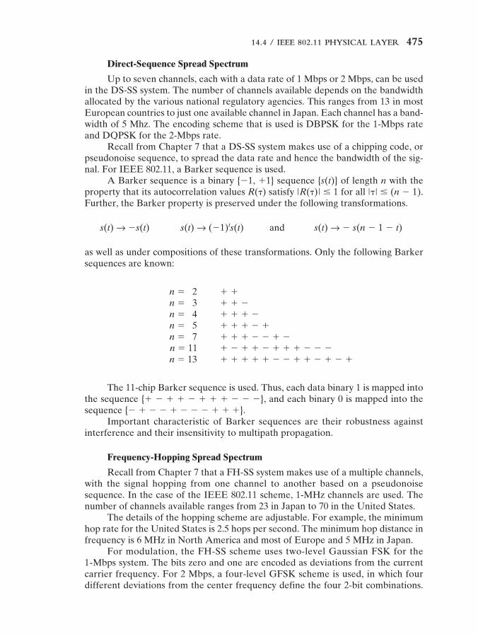
IEEE 802.11b is an extension of the IEEE 802.11 DS-SS scheme, providing datarates of 5.5 and 11 Mbps. The chipping rate is 11 MHz, which is the same as the orig-inal DS-SS scheme, thus providing the same occupied bandwidth. To achieve ahigher data rate in the same bandwidth at the same chipping rate, a modulationscheme known as complementary code keying (CCK) is used.
The CCK modulation scheme is quite complex and is not examined in detail here.Figure 14.10 provides an overview of the scheme for the 11-Mbps rate. Input data are
14 StallingsIII 5/31/01 9:03 PM Page 476
14.6 / KEY TERMS AND REVIEW QUESTIONS 477
treated in blocks of 8 bits at a rate of 1.375 MHz (8 bits/symbol � 1.375 MHz � 11Mbps). Six of these bits are mapped into one of 64 codes sequences based on theuse of the 8 � 8 Walsh matrix (Figure 7.17). The output of the mapping, plus thetwo additional bits, forms the input to a QPSK modulator.
14.5 RECOMMENDED READING AND WEB SITES
[OHAR99] is an excellent technical treatment of IEEE 802.11. [GEIE99] also providesdetailed coverage of the IEEE 802.11 standards, and numerous case studies. [CROW97] is agood survey article on the 802.11 standards. Neither of the last two references covers IEEE802.11a and IEEE 802.11b. [GEIE01] has a good discussion of IEEE 802.11a.
CROW97 Crow, B., et al. “IEEE 802.11 Wireless Local Area Networks.” IEEE Com-munications Magazine, September 1997.
GEIE99 Geier, J. Wireless LANs. New York: Macmillan Technical Publishing, 1999.GEIE01 Geier, J. “Enabling Fast Wireless Networks with OFDM.” Communications
System Design, February 2001. (www.csdmag.com)OHAR99 Ohara, B., and Petrick, A. IEEE 802.11 Handbook: A Designer’s Companion.
New York: IEEE Press, 1999.
Recommended Web sites:
• The IEEE 802.11 Wireless LAN Working Group: Contains working groupdocuments plus discussion archives.
• Wireless Ethernet Compatibility Alliance: An industry group promoting theinteroperability of 802.11 products with each other and with Ethernet.
14.6 KEY TERMS AND REVIEW QUESTIONS
Key Terms
access point (AP) distribution system (DS) open system Barker sequence extended service set authenticationbasic service set (BSS) (ESS) point coordinationbinary exponential logical link control (LLC) function (PCF)
backoff MAC protocol data unit shared key complementary code (MPDU) authentication
keying (CCK) MAC service data unit wired equivalentcoordination function (MSDU) privacy (WEP)distributed coordination medium access control
function (DCF) (MAC)
14 StallingsIII 5/31/01 9:03 PM Page 477
478 CHAPTER 14 / IEEE 802.11 WIRELESS LAN STANDARD
Review Questions1 List and briefly define the IEEE 802 protocol layers.2 What is the difference between a MAC address and an LLC address?3 List and briefly define LLC services.4 What is the difference between an access point and a portal?5 Is a distribution system a wireless network?6 List and briefly define IEEE 802.11 services.7 How is the concept of an association related to that of mobility?8 What characteristics of a wireless LAN present unique security challenges not found
in wired LANs?9 Which form of authentication is more secure and why: open system authentication or
shared key authentication?
14 StallingsIII 5/31/01 9:03 PM Page 478


![Whirlpool Awe 2214 [ET]](https://img.pdfslide.us/doc/110x75/552aed114a795932118b45d7/whirlpool-awe-2214-et.jpg)