Embed Size (px)
DESCRIPTION
proteccion de motores electricos de inducción o de jaula de ardilla, funciones de sobrecarga, cortocircuito, arranque, fallas a tiuerra, etc..
Citation preview
Motor Protection
Technical literature supporting this section:
IEEE Guide for AC Motor Protection, IEEE C37.96, IEEE Press, 2000.
IEEE Guide for the Presentation of Thermal Limit Curves for Squirrel Cage Induction Machines,IEEE 620, IEEE Press, 1996.
NEMA Std. MG 1-2011, “Motors and Generators,” National Electrical Manufacturers Association, 2012.
S.E. Zocholl, AC Motor Protection, Pullman, WA: Schweitzer Engineering Laboratories, Inc., 2003.
S.E. Zocholl, “Comparing Motor Thermal Models,” in 31st Annual Western Protective Relay Conference, Spokane, WA, October 19–21, 2004, Available at www.selinc.com.
S.E. Zocholl, “Tutorial: From the Steinmetz Model to the Protection of High Inertia Drives,” in 33rd Annual Western Protective Relay Conference, Spokane, WA, October 17–19, 2006, Available at www.selinc.com.
S.E. Zocholl, “Understanding Service Factor, Thermal Models, and Overloads,” Available at www.selinc.com.
S.E. Zocholl and G. Benmouyal, “Using Thermal Limit Curves to Define Thermal Models of Induction Motors,” in 28th Annual Western Protective Relay Conference, Spokane, WA, October 23–25, 2001, Available at www.selinc.com.
S.E. Zocholl and A. Guzman, “Thermal Models in Power System Protection,” in 26th Annual Western Protective Relay Conference, Spokane, WA, October 26–28, 1999, Available at www.selinc.com.
S.E. Zocholl, E.O. Schweitzer, and A. Aliaga-Zegarra, “Thermal Protection of Induction Motors Enhanced by Interactive Electrical and Thermal Models,” IEEE Power Engineering Review, vol. PER-4, no. 7, pp. 17491755, July 1984.
1PROT401_MotorProtection_r7
Motor Protection
This section describes the motor main characteristics and the most common types of faults and abnormal operating conditions to which a motor can be subjected. Additionally, we will describe and discuss the motor protection principles that are used to detect and protect for these conditions.
A fault can be defined as an actual dielectric failure of the motor insulation system. An abnormal operating condition is a condition that is hazardous to the motor if it is allowed to continue to operate, and it can lead to failure.
The protection functions discussed in this section can be implemented by separate relays and/or multifunction microprocessor-based relays.
2PROT401_MotorProtection_r7
Motor Protection
In this subsection, we will discuss:
• Basic motor design concepts
• Motor characteristics during starting and running
• Induction motor equivalent circuit
• Motor thermal limit curves
• Motor faults and abnormal operating conditions
3PROT401_MotorProtection_r7
Motor Protection
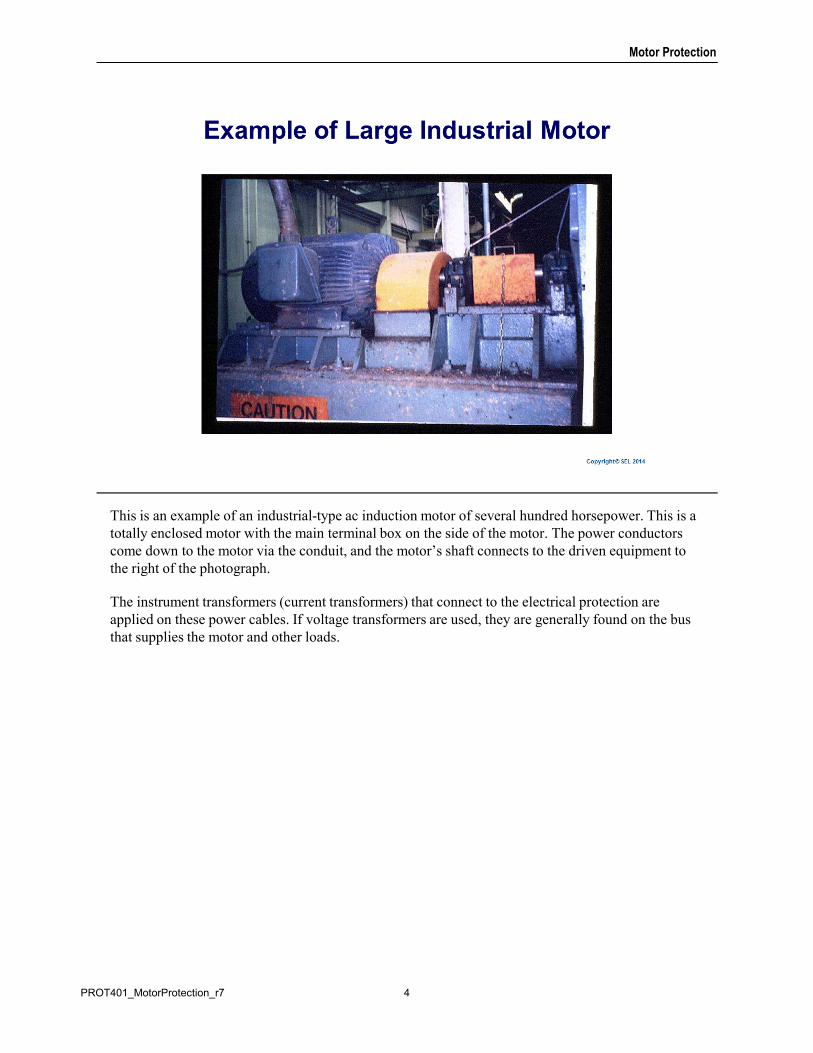
This is an example of an industrial-type ac induction motor of several hundred horsepower. This is a totally enclosed motor with the main terminal box on the side of the motor. The power conductors come down to the motor via the conduit, and the motor’s shaft connects to the driven equipment to the right of the photograph.
The instrument transformers (current transformers) that connect to the electrical protection are applied on these power cables. If voltage transformers are used, they are generally found on the bus that supplies the motor and other loads.
4PROT401_MotorProtection_r7
Motor Protection
The slide lists the different types of ac motors.
In a squirrel cage rotor, the rotor windings are bars that are short-circuited together by rings at the end of the rotor. A wound rotor has an actual three-phase winding comprising the rotor circuit.
Synchronous motors have a wound rotor dc winding and have their own excitation system. These motors typically have a squirrel cage for starting. Salient-pole rotors have a nonuniform air gap, and round rotors have a uniform air gap.
In this course, we will focus on squirrel cage induction motors, although we will mention synchronous motors and wound rotor induction motor principles and requirements.
5PROT401_MotorProtection_r7
Motor Protection
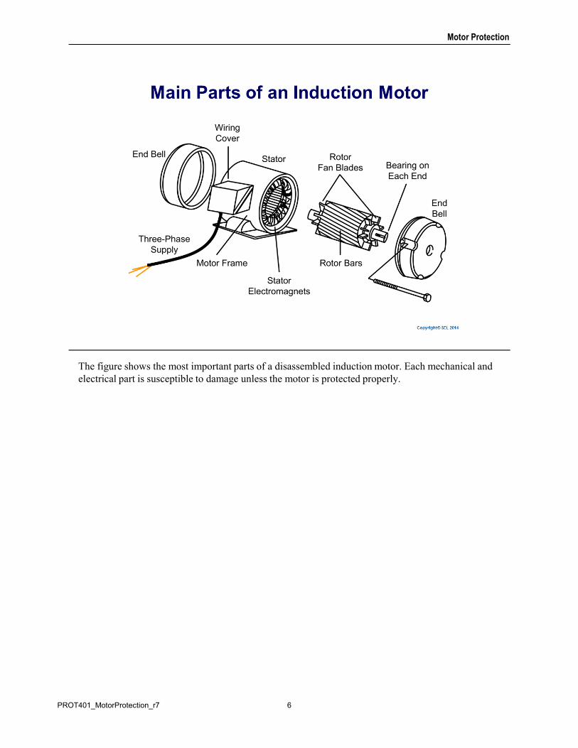
The figure shows the most important parts of a disassembled induction motor. Each mechanical and electrical part is susceptible to damage unless the motor is protected properly.
6PROT401_MotorProtection_r7
Motor Protection
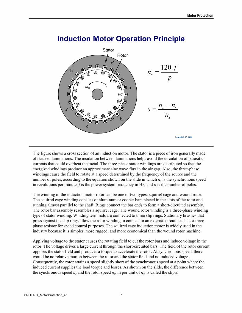
The figure shows a cross section of an induction motor. The stator is a piece of iron generally made of stacked laminations. The insulation between laminations helps avoid the circulation of parasitic currents that could overheat the metal. The three-phase stator windings are distributed so that the energized windings produce an approximate sine wave flux in the air gap. Also, the three-phase windings cause the field to rotate at a speed determined by the frequency of the source and the number of poles, according to the equation shown on the slide in which ns is the synchronous speed in revolutions per minute, f is the power system frequency in Hz, and p is the number of poles.
The winding of the induction motor rotor can be one of two types: squirrel cage and wound rotor. The squirrel cage winding consists of aluminum or cooper bars placed in the slots of the rotor and running almost parallel to the shaft. Rings connect the bar ends to form a short-circuited assembly. The rotor bar assembly resembles a squirrel cage. The wound rotor winding is a three-phase winding type of stator winding. Winding terminals are connected to three slip rings. Stationary brushes that press against the slip rings allow the rotor winding to connect to an external circuit, such as a three-phase resistor for speed control purposes. The squirrel cage induction motor is widely used in the industry because it is simpler, more rugged, and more economical than the wound rotor machine.
Applying voltage to the stator causes the rotating field to cut the rotor bars and induce voltage in the rotor. The voltage drives a large current through the short-circuited bars. The field of the rotor current opposes the stator field and produces a torque to accelerate the rotor. At synchronous speed, there would be no relative motion between the rotor and the stator field and no induced voltage. Consequently, the rotor attains a speed slightly short of the synchronous speed at a point where the induced current supplies the load torque and losses. As shown on the slide, the difference between the synchronous speed ns and the rotor speed nr, in per unit of ns, is called the slip s.
7PROT401_MotorProtection_r7
Motor Protection
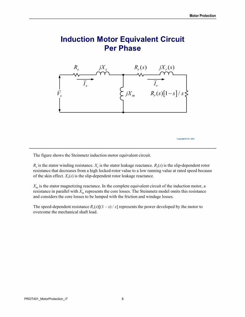
The figure shows the Steinmetz induction motor equivalent circuit.
Rs is the stator winding resistance. Xs is the stator leakage reactance. Rr(s) is the slip-dependent rotor resistance that decreases from a high locked-rotor value to a low running value at rated speed because of the skin effect. Xr(s) is the slip-dependent rotor leakage reactance.
Xm is the stator magnetizing reactance. In the complete equivalent circuit of the induction motor, a resistance in parallel with Xm represents the core losses. The Steinmetz model omits this resistance and considers the core losses to be lumped with the friction and windage losses.
The speed-dependent resistance Rr(s)[(1 – s) / s] represents the power developed by the motor to overcome the mechanical shaft load.
8PROT401_MotorProtection_r7
Motor Protection
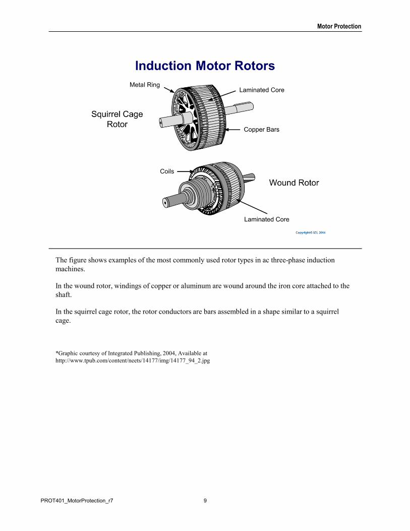
The figure shows examples of the most commonly used rotor types in ac three-phase induction machines.
In the wound rotor, windings of copper or aluminum are wound around the iron core attached to the shaft.
In the squirrel cage rotor, the rotor conductors are bars assembled in a shape similar to a squirrel cage.
*Graphic courtesy of Integrated Publishing, 2004, Available at http://www.tpub.com/content/neets/14177/img/14177_94_2.jpg
9PROT401_MotorProtection_r7
Motor Protection
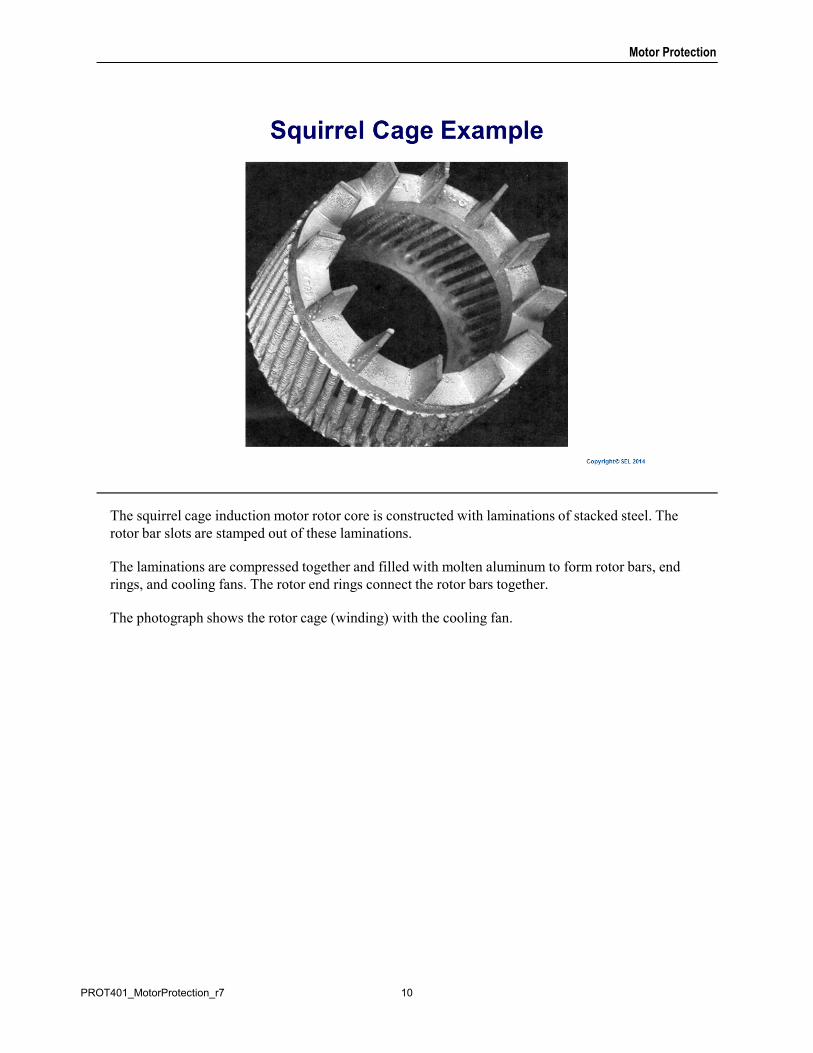
The squirrel cage induction motor rotor core is constructed with laminations of stacked steel. The rotor bar slots are stamped out of these laminations.
The laminations are compressed together and filled with molten aluminum to form rotor bars, end rings, and cooling fans. The rotor end rings connect the rotor bars together.
The photograph shows the rotor cage (winding) with the cooling fan.
10PROT401_MotorProtection_r7
Motor Protection
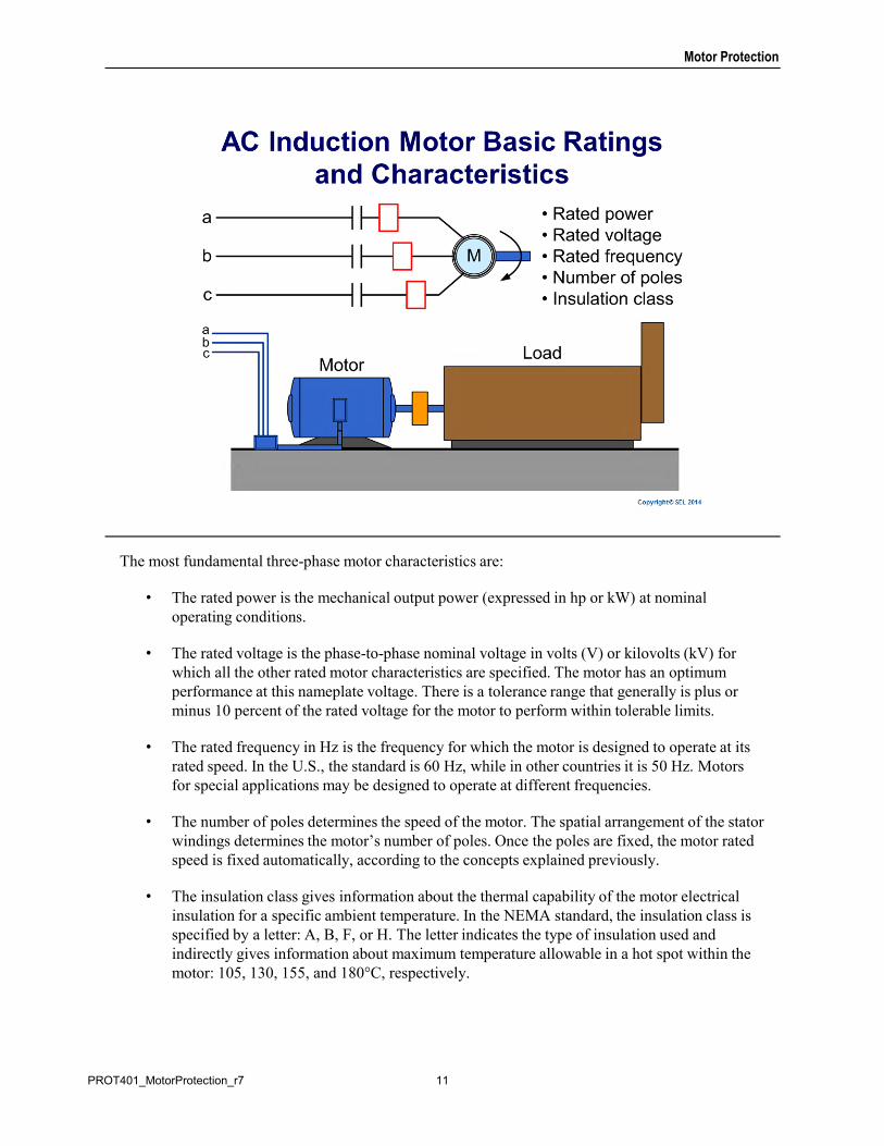
The most fundamental three-phase motor characteristics are:
• The rated power is the mechanical output power (expressed in hp or kW) at nominal operating conditions.
• The rated voltage is the phase-to-phase nominal voltage in volts (V) or kilovolts (kV) for which all the other rated motor characteristics are specified. The motor has an optimum performance at this nameplate voltage. There is a tolerance range that generally is plus or minus 10 percent of the rated voltage for the motor to perform within tolerable limits.
• The rated frequency in Hz is the frequency for which the motor is designed to operate at its rated speed. In the U.S., the standard is 60 Hz, while in other countries it is 50 Hz. Motors for special applications may be designed to operate at different frequencies.
• The number of poles determines the speed of the motor. The spatial arrangement of the stator windings determines the motor’s number of poles. Once the poles are fixed, the motor rated speed is fixed automatically, according to the concepts explained previously.
• The insulation class gives information about the thermal capability of the motor electrical insulation for a specific ambient temperature. In the NEMA standard, the insulation class is specified by a letter: A, B, F, or H. The letter indicates the type of insulation used and indirectly gives information about maximum temperature allowable in a hot spot within the motor: 105, 130, 155, and 180°C, respectively.
11PROT401_MotorProtection_r7
Motor Protection
The National Electrical Manufacturers Association (NEMA) defines service factor in section MG1 -1.43 of their manual as, “The service factor of an alternating current (AC) motor is a multiplier which, when applied to the rated horsepower, indicates a permissible horsepower loading which may be carried under the conditions specified for the service factor.”
The conditions under which service factor may be applied are described in NEMA MG1 - 14.36 as, “When the voltage and frequency are maintained at the value specified on the motor's nameplate, the motor may be overloaded up to the horsepower obtained by multiplying the rated horsepower by the service factor shown on the nameplate.”
The service factor can be found on the motor nameplate and data sheet. A 1.0 service factor motor should not be overloaded.
Common service factor ratings found in the industry are 1.15 and 1.25. A 1.25 service factor motor can be loaded to 125 percent times full-load power when all other parameters, such as voltage and frequency, are at rated values. A 1.15 service factor on a 1000 hp motor would allow it to be run continuously at a 15 percent overload (1150 hp).
A motor will reach higher than rated temperature when operating continuously at the service factor load. For example, a motor will run 15 to 25 degrees hotter when operating at 1.15 service factor than it will when running at rated nameplate load. This higher than rated temperature reduces the expected insulation life: any motor operated at service factor continuously will have a shorter thermal life expectancy than it will if run at or below rated load.
12PROT401_MotorProtection_r7
Motor Protection
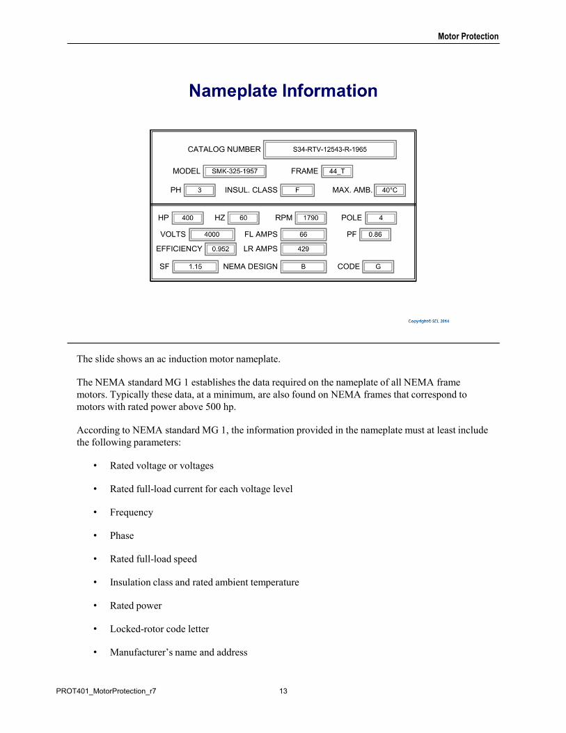
The slide shows an ac induction motor nameplate.
The NEMA standard MG 1 establishes the data required on the nameplate of all NEMA frame motors. Typically these data, at a minimum, are also found on NEMA frames that correspond to motors with rated power above 500 hp.
According to NEMA standard MG 1, the information provided in the nameplate must at least include the following parameters:
• Rated voltage or voltages
• Rated full-load current for each voltage level
• Frequency
• Phase
• Rated full-load speed
• Insulation class and rated ambient temperature
• Rated power
• Locked-rotor code letter
• Manufacturer’s name and address
13PROT401_MotorProtection_r7
Motor Protection
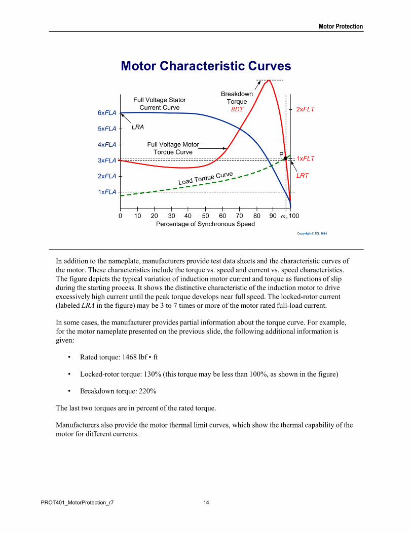
In addition to the nameplate, manufacturers provide test data sheets and the characteristic curves of the motor. These characteristics include the torque vs. speed and current vs. speed characteristics. The figure depicts the typical variation of induction motor current and torque as functions of slip during the starting process. It shows the distinctive characteristic of the induction motor to drive excessively high current until the peak torque develops near full speed. The locked-rotor current (labeled LRA in the figure) may be 3 to 7 times or more of the motor rated full-load current.
In some cases, the manufacturer provides partial information about the torque curve. For example, for the motor nameplate presented on the previous slide, the following additional information is given:
• Rated torque: 1468 lbf • ft
• Locked-rotor torque: 130% (this torque may be less than 100%, as shown in the figure)
• Breakdown torque: 220%
The last two torques are in percent of the rated torque.
Manufacturers also provide the motor thermal limit curves, which show the thermal capability of the motor for different currents.
14PROT401_MotorProtection_r7
Motor Protection
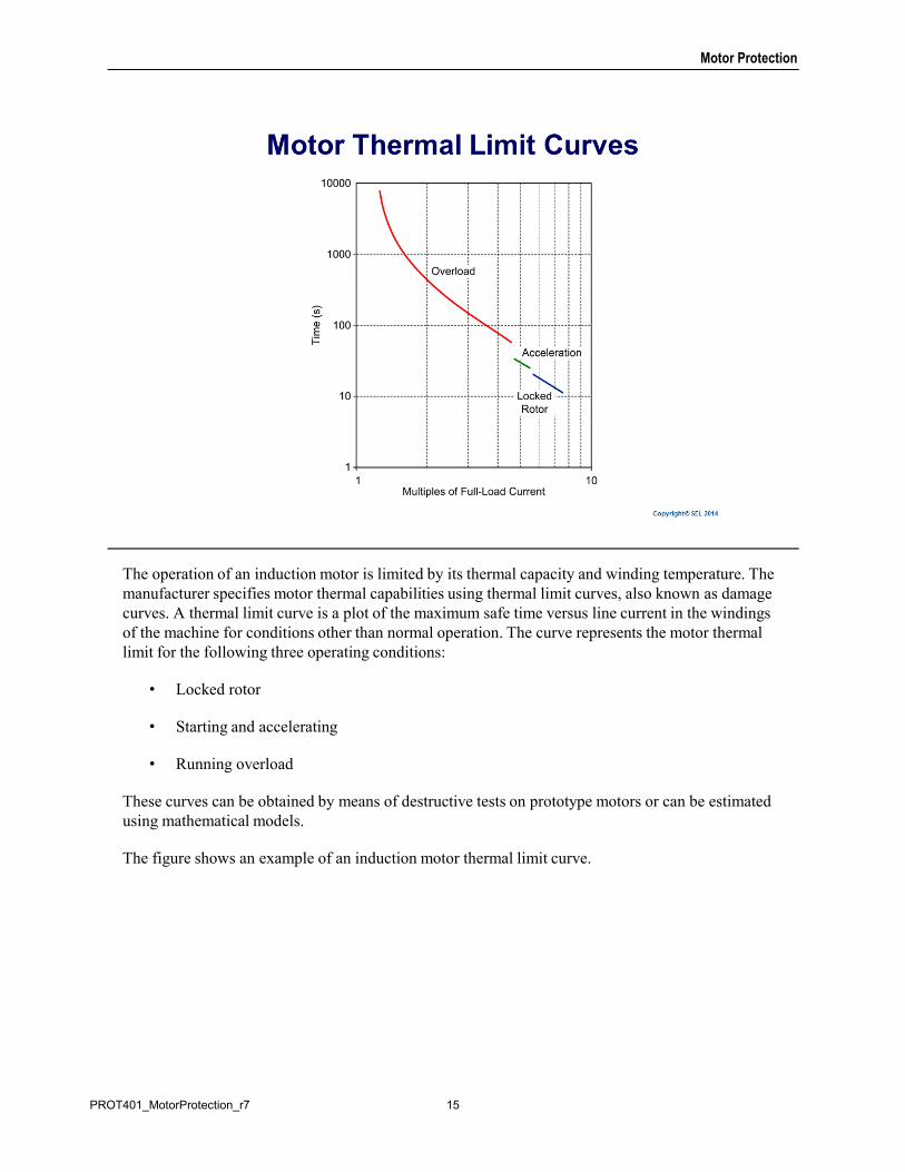
The operation of an induction motor is limited by its thermal capacity and winding temperature. The manufacturer specifies motor thermal capabilities using thermal limit curves, also known as damage curves. A thermal limit curve is a plot of the maximum safe time versus line current in the windings of the machine for conditions other than normal operation. The curve represents the motor thermal limit for the following three operating conditions:
• Locked rotor
• Starting and accelerating
• Running overload
These curves can be obtained by means of destructive tests on prototype motors or can be estimated using mathematical models.
The figure shows an example of an induction motor thermal limit curve.
15PROT401_MotorProtection_r7
Motor Protection
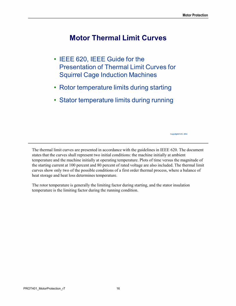
The thermal limit curves are presented in accordance with the guidelines in IEEE 620. The document states that the curves shall represent two initial conditions: the machine initially at ambient temperature and the machine initially at operating temperature. Plots of time versus the magnitude of the starting current at 100 percent and 80 percent of rated voltage are also included. The thermal limit curves show only two of the possible conditions of a first order thermal process, where a balance of heat storage and heat loss determines temperature.
The rotor temperature is generally the limiting factor during starting, and the stator insulation temperature is the limiting factor during the running condition.
16PROT401_MotorProtection_r7
Motor Protection
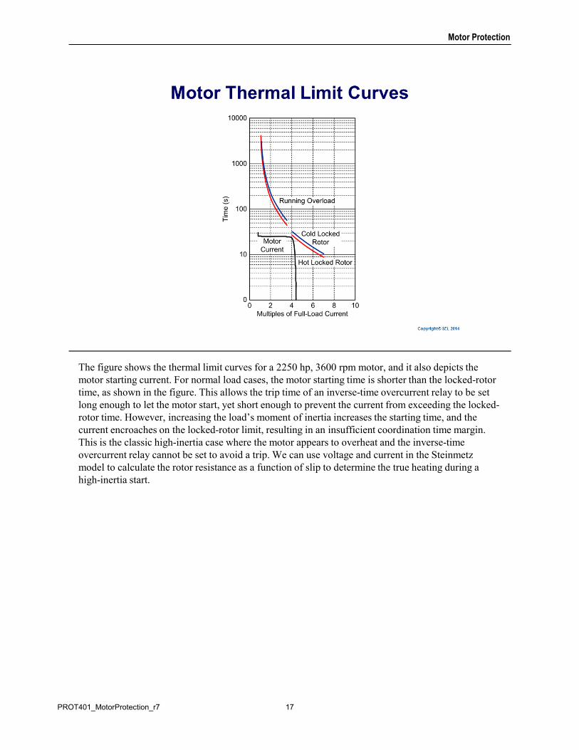
The figure shows the thermal limit curves for a 2250 hp, 3600 rpm motor, and it also depicts the motor starting current. For normal load cases, the motor starting time is shorter than the locked-rotor time, as shown in the figure. This allows the trip time of an inverse-time overcurrent relay to be set long enough to let the motor start, yet short enough to prevent the current from exceeding the locked-rotor time. However, increasing the load’s moment of inertia increases the starting time, and the current encroaches on the locked-rotor limit, resulting in an insufficient coordination time margin. This is the classic high-inertia case where the motor appears to overheat and the inverse-time overcurrent relay cannot be set to avoid a trip. We can use voltage and current in the Steinmetz model to calculate the rotor resistance as a function of slip to determine the true heating during a high-inertia start.
17PROT401_MotorProtection_r7
Motor Protection
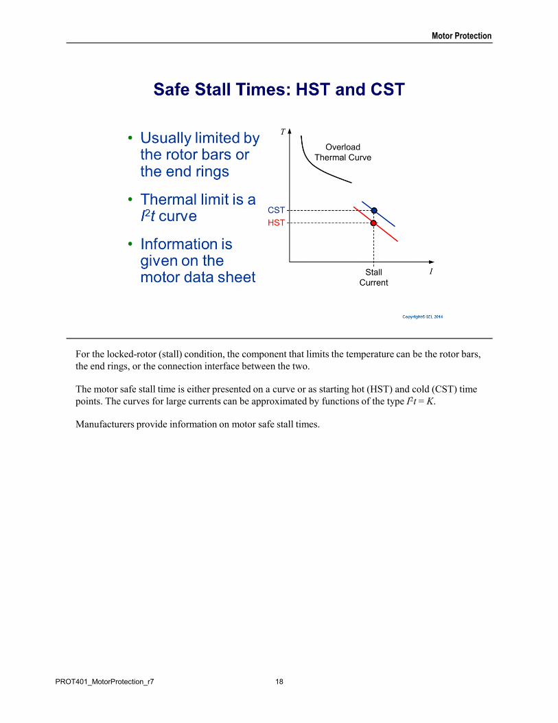
For the locked-rotor (stall) condition, the component that limits the temperature can be the rotor bars, the end rings, or the connection interface between the two.
The motor safe stall time is either presented on a curve or as starting hot (HST) and cold (CST) time points. The curves for large currents can be approximated by functions of the type I2t = K.
Manufacturers provide information on motor safe stall times.
18PROT401_MotorProtection_r7
Motor Protection
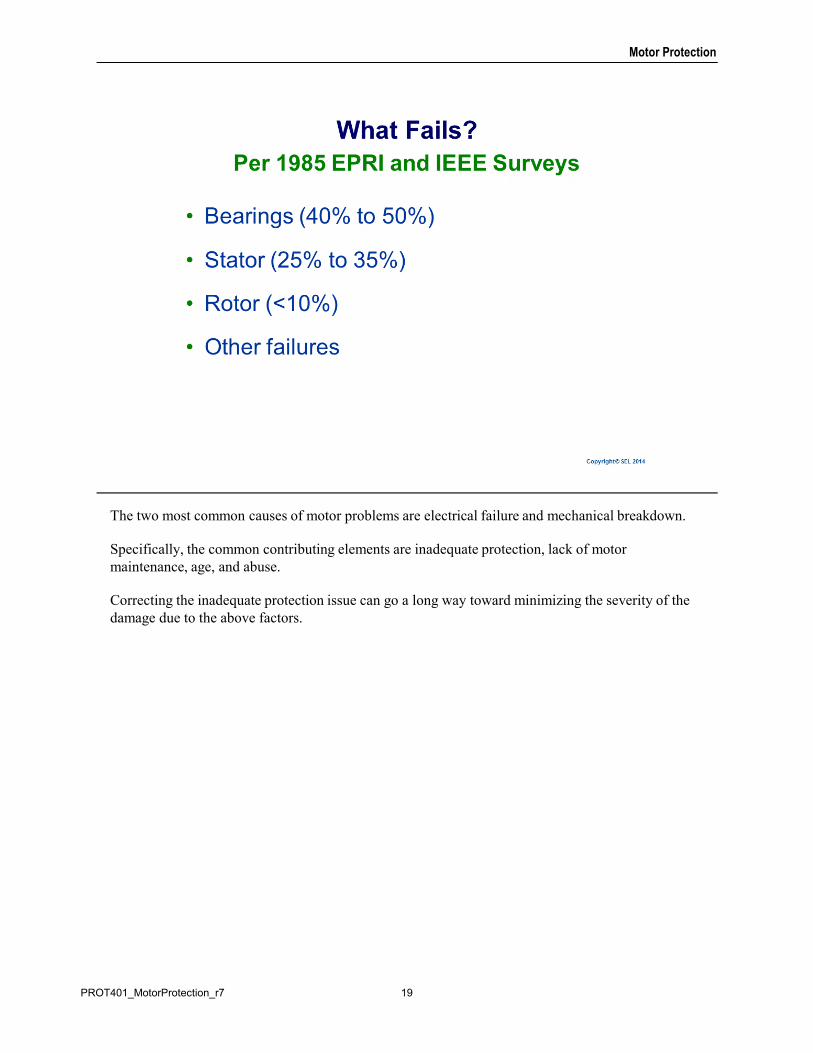
The two most common causes of motor problems are electrical failure and mechanical breakdown.
Specifically, the common contributing elements are inadequate protection, lack of motor maintenance, age, and abuse.
Correcting the inadequate protection issue can go a long way toward minimizing the severity of the damage due to the above factors.
19PROT401_MotorProtection_r7
Motor Protection
Insulation systems lose their physical and dielectric integrity over time from mechanical stress, contaminants in the insulation, and heat. Excessive temperatures substantially accelerate the decay process. Elevated temperature reduces the ability of the insulation to withstand electrical or mechanical stress. The temperature level at which the insulation should be protected is a matter of judgment with some guidance from the standards (such as NEMA MG 1). Insulation failures cause motor internal faults.
Motor internal faults are usually phase to ground or phase to phase, with or without involving ground. Generally, three-phase faults occur near the terminals and do not involve ground. Motor design can impact the likelihood of certain types of faults.
The magnitude of the fault current depends on the fault type, the source strength, the size and length of the motor cables, the location of the fault in the motor winding, and the fault resistance. Ground fault current also depends on the type of system grounding.
Turn-to-turn faults occur when dielectric failure of turn and/or strand insulation causes overheating and leads to subsequent faults to ground or other phases.
Synchronous motors and wound rotor induction motors should have rotor winding ground protection.
The wound rotor induction motor is a wound field similar to the synchronous motor, but it has a three-phase ac winding. You can apply a zero-sequence voltage detection scheme that uses three voltage transformers with a resistor.
20PROT401_MotorProtection_r7
Motor Protection
Motor overheating can result from continuous or intermittent overload, unbalanced or low-voltage operation, locked-rotor condition during start, or from blocked cooling or high ambient temperature.
Induction motors that have a large heat storage capacity and slight, balanced overloads for short periods of time do not produce damaging temperature excursions. Motor manufacturers indicate the maximum temperature with thermal limit curves.
Motor operation under voltage unbalance conditions causes negative-sequence current. A voltage unbalance of 1 percent may lead to a 6 percent current unbalance. The rotor negative-sequence resistance is higher than the positive-sequence resistance. As a result, unbalanced motor operation may cause excessive rotor heating even for normal load currents.
Locked-rotor current causes such a high rate of rise of the rotor temperature that there is little time for heat loss before it reaches the limiting temperature.
A low-voltage condition that occurs during motor normal operation can cause the motor to jam. If low voltage occurs during starting, the motor may not start normally, because the motor torque could be less than the load torque. In both cases, the resulting overcurrent can damage the motor.
Inadequate or poor ventilation causes reduced coolant flow to the motor parts that need the heat transfer. Clogged ventilating passages, screens, filters, or devices in the motor air stream cause the motor to run hot.
In large motors, loss of cooling and/or high ambient temperature can cause the motor components to rise above their temperature ratings. We need temperature detectors to detect and protect for these adverse conditions. For large motors, it is common practice to use RTDs to detect, alarm, and protect the motor.
21PROT401_MotorProtection_r7
Motor Protection
Motor stall occurs when, during the start operation, the motor torque cannot overpower the load torque. Then the motor cannot start moving. The cause of a locked rotor may be failure of load bearings, failure of the motor bearings, low supply voltage, single phasing, or load exceeding the motor torque. When the rotor is locked, the stator mimics a transformer with a resistance-loaded secondary and typically experiences current of 6 times rated. Due to the rotor resistance at locked rotor being three times greater than at running conditions, the effective heating due to rotor ohmic losses is 108 times that of normal operation.
Reduced speed operation, frequent starts/jogging, or phase reversal conditions can cause overheating of the stator windings and rotor, resulting in a temperature rise of these parts above the design limits. This may damage the insulation system, causing premature failure.
22PROT401_MotorProtection_r7
Motor Protection
The field winding and dc excitation system are unique to synchronous motors.
A field winding can fail to ground, and this condition should be detected even though it is a floating dc system (ungrounded). A second field winding ground fault can occur and can lead to circulating current, overheating, and ultimately catastrophic failure of the field winding and other components.
Loss of excitation is another condition that should be detected. It can have detrimental effects on both the motor and power distribution system. The synchronous motor may be providing reactive power to support system voltage. With the loss of excitation, the motor becomes inductive and absorbs reactive power from the power distribution system. In addition, the bus, and possibly the power distribution system voltage, becomes unacceptably low.
Out-of-step operation can cause motor damage because of high, pulsating torques.
23PROT401_MotorProtection_r7
Motor Protection
In this subsection, we will discuss:
• Motor protection schemes
• Motor thermal protection
• Motor short-circuit protection
24PROT401_MotorProtection_r7
Motor Protection
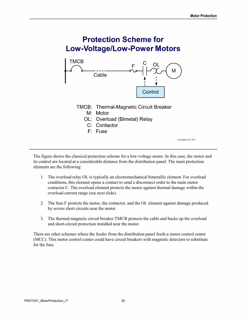
The figure shows the classical protection scheme for a low-voltage motor. In this case, the motor and its control are located at a considerable distance from the distribution panel. The main protection elements are the following:
1. The overload relay OL is typically an electromechanical bimetallic element. For overload conditions, this element opens a contact to send a disconnect order to the main motor contactor C. The overload element protects the motor against thermal damage within the overload current range (see next slide).
2. The fuse F protects the motor, the contactor, and the OL element against damage produced by severe short circuits near the motor.
3. The thermal-magnetic circuit breaker TMCB protects the cable and backs up the overload and short-circuit protection installed near the motor.
There are other schemes where the feeder from the distribution panel feeds a motor control center (MCC). This motor control center could have circuit breakers with magnetic detectors to substitute for the fuse.
25PROT401_MotorProtection_r7
Motor Protection
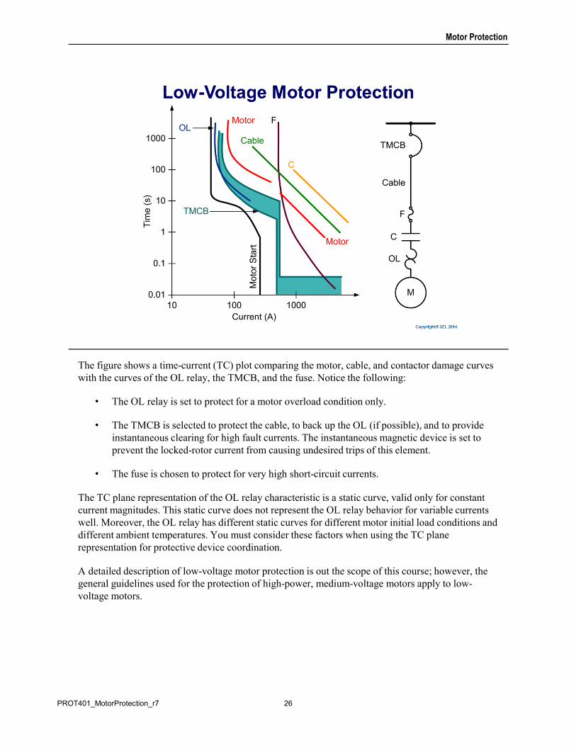
The figure shows a time-current (TC) plot comparing the motor, cable, and contactor damage curves with the curves of the OL relay, the TMCB, and the fuse. Notice the following:
• The OL relay is set to protect for a motor overload condition only.
• The TMCB is selected to protect the cable, to back up the OL (if possible), and to provide instantaneous clearing for high fault currents. The instantaneous magnetic device is set to prevent the locked-rotor current from causing undesired trips of this element.
• The fuse is chosen to protect for very high short-circuit currents.
The TC plane representation of the OL relay characteristic is a static curve, valid only for constant current magnitudes. This static curve does not represent the OL relay behavior for variable currents well. Moreover, the OL relay has different static curves for different motor initial load conditions and different ambient temperatures. You must consider these factors when using the TC plane representation for protective device coordination.
A detailed description of low-voltage motor protection is out the scope of this course; however, the general guidelines used for the protection of high-power, medium-voltage motors apply to low-voltage motors.
26PROT401_MotorProtection_r7
Motor Protection
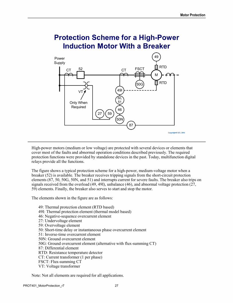
High-power motors (medium or low voltage) are protected with several devices or elements that cover most of the faults and abnormal operation conditions described previously. The required protection functions were provided by standalone devices in the past. Today, multifunction digital relays provide all the functions.
The figure shows a typical protection scheme for a high-power, medium-voltage motor when a breaker (52) is available. The breaker receives tripping signals from the short-circuit protection elements (87, 50, 50G, 50N, and 51) and interrupts current for severe faults. The breaker also trips on signals received from the overload (49, 49I), unbalance (46), and abnormal voltage protection (27, 59) elements. Finally, the breaker also serves to start and stop the motor.
The elements shown in the figure are as follows:
49: Thermal protection element (RTD based)49I: Thermal protection element (thermal model based)46: Negative-sequence overcurrent element27: Undervoltage element59: Overvoltage element50: Short-time delay or instantaneous phase overcurrent element51: Inverse-time overcurrent element50N: Ground overcurrent element50G: Ground overcurrent element (alternative with flux-summing CT)87: Differential elementRTD: Resistance temperature detector CT: Current transformer (1 per phase)FSCT: Flux-summing CTVT: Voltage transformer
Note: Not all elements are required for all applications.
27PROT401_MotorProtection_r7
Motor Protection
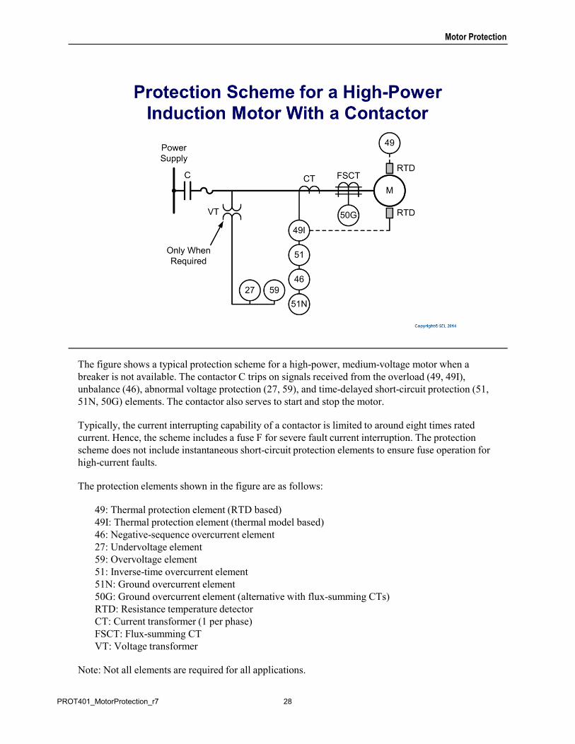
The figure shows a typical protection scheme for a high-power, medium-voltage motor when a breaker is not available. The contactor C trips on signals received from the overload (49, 49I), unbalance (46), abnormal voltage protection (27, 59), and time-delayed short-circuit protection (51,51N, 50G) elements. The contactor also serves to start and stop the motor.
Typically, the current interrupting capability of a contactor is limited to around eight times rated current. Hence, the scheme includes a fuse F for severe fault current interruption. The protection scheme does not include instantaneous short-circuit protection elements to ensure fuse operation for high-current faults.
The protection elements shown in the figure are as follows:
49: Thermal protection element (RTD based)49I: Thermal protection element (thermal model based)46: Negative-sequence overcurrent element27: Undervoltage element59: Overvoltage element51: Inverse-time overcurrent element51N: Ground overcurrent element50G: Ground overcurrent element (alternative with flux-summing CTs)RTD: Resistance temperature detector CT: Current transformer (1 per phase)FSCT: Flux-summing CTVT: Voltage transformer
Note: Not all elements are required for all applications.
28PROT401_MotorProtection_r7
Motor Protection
29PROT401_MotorProtection_r7
Motor Protection
The purpose of motor thermal protection is to allow the motor to start and run within the manufacturer’s published guidelines but to trip if the motor heat energy exceeds those ratings because of overloads, negative-sequence current, locked-rotor starting, or too frequent starting.
Motor thermal protection prevents motor damage when the mechanical loading above the motor rating is applied while the motor is running. Running overloads typically affect the stator winding insulation. Unbalanced system conditions can cause adverse heating effects on a motor and require thermal protection. For unbalance conditions, the negative-sequence current causes excessive heating of the rotor components.
Thermal protection is also required for locked-rotor protection at starting. A locked-rotor condition occurs when a motor starts and the connected load’s moment of inertia is large enough to create shaft torque greater than the motor starting torque capability. The voltage drop at the terminals caused by high starting current affects this motor’s starting torque capability as well.
Total or partial loss of cooling and/or high ambient temperature can cause the motor components to rise above their temperature ratings. For large motors, it is common practice to use RTDs to detect, alarm, and protect the motor.
30PROT401_MotorProtection_r7
Motor Protection
There are two methods of motor thermal protection. One method uses resistive temperature detectors (RTDs) to directly measure the motor temperature. The other method measures the motor stator currents and, in some cases, voltages. Voltages are used with current to calculate slip-dependent rotor resistance. In microprocessor-based relays, the thermal models may also receive temperature data measured by the RTDs.
31PROT401_MotorProtection_r7
Motor Protection
RTDs are mounted at appropriate locations within or on the motor frame so that the temperature at the RTDs will change in proportion to the motor winding temperature. The RTDs must be selected to match the insulation class.
RTD-based protection provides good stator thermal protection for balanced, slow-varying overloads. It can detect, for example, motor overheating because of blocked cooling. Additional RTDs on motor and drive gearings provide temperature information for the relay to detect impending mechanical problems. RTDs may also provide ambient temperature information.
RTD-based thermal protection is a good solution for large motors, but it must be complemented with a current-based thermal protection.
RTDs fail to provide reliable stator information for unbalanced operating conditions.
Unfortunately, the slow response of RTDs reduces their value to detect fast motor heating during start. This protection alone may not be adequate for protection against locked-rotor and frequent starting. Additionally, the heating problems during starting conditions are mostly manifested in the rotor, making RTD transmission difficult and expensive.
32PROT401_MotorProtection_r7
Motor Protection
Most low-power, low-voltage induction motors are protected against damage from running overloads by properly selected electromechanical bimetallic thermal elements. After the motor trips, the thermal relay must cool before it can be reset. Because of its smaller mass, the relay’s cooling characteristics cannot match those of the motor.
For medium-voltage motors, users relied in the past on inverse-time phase overcurrent elements and a separate negative-sequence overcurrent element to detect currents that could lead to overheating. Neither time-overcurrent protection nor RTDs account for thermal history or accurately track the excursions of conductor temperatures.
A better approach for motor thermal protection is to use thermal models that account for the slip-dependent I2r heating of both positive- and negative-sequence current. The thermal model is defined by motor nameplate and thermal limit data. This mathematical model calculates the motor temperature in real time. The temperature is then compared to thermal limit trip and alarm thresholds to prevent overheating from overload, locked rotor, too frequent or prolonged starts, or unbalanced current.
33PROT401_MotorProtection_r7
Motor Protection
Electromechanical bimetallic thermal elements provide a level of thermal protection to small, low-voltage motors (600 volts and less).
These relatively simple devices are limited by the problems listed on the slide.
34PROT401_MotorProtection_r7
Motor Protection
The thermal model calculates and monitors the motor temperature to prevent overheating during starting and running conditions. The thermal model is the time-discrete form of the differential equation for temperature rise caused by current in a conductor. The models are derived from fundamental principles and rely on parameters defined by motor data. They can be visualized as an electric analog circuit, and the temperature can be expressed in units of I2t.
The rotor thermal model includes an adiabatic model for the motor starting process and a first order model for the motor normal running condition. The stator thermal model is a first order model that represents the motor normal running condition.
During a start, the motor heats up very fast without losing thermal energy to the surrounding environment. In this adiabatic process, the motor temperature grows continuously until the starting current decreases to a normal value or the motor is disconnected. The adiabatic model includes a high I2t trip threshold specified by the locked-rotor limit during a start.
During the motor normal running condition, the motor cools down by losing thermal energy to the surroundings. A first order thermal model describes this operating condition. This model has a lower trip threshold for the normal running condition specified by the service factor. Therefore, the thermal model requires a trip threshold for starting, indicated by the locked-rotor thermal limit, and a trip threshold for running, indicated by the service factor.
35PROT401_MotorProtection_r7
Motor Protection
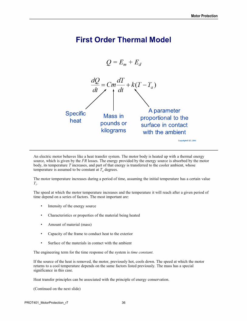
An electric motor behaves like a heat transfer system. The motor body is heated up with a thermal energy source, which is given by the I2R losses. The energy provided by the energy source is absorbed by the motor body, its temperature T increases, and part of that energy is transferred to the cooler ambient, whose temperature is assumed to be constant at Ta degrees.
The motor temperature increases during a period of time, assuming the initial temperature has a certain value Ti.
The speed at which the motor temperature increases and the temperature it will reach after a given period of time depend on a series of factors. The most important are:
• Intensity of the energy source
• Characteristics or properties of the material being heated
• Amount of material (mass)
• Capacity of the frame to conduct heat to the exterior
• Surface of the materials in contact with the ambient
The engineering term for the time response of the system is time constant.
If the source of the heat is removed, the motor, previously hot, cools down. The speed at which the motor returns to a cool temperature depends on the same factors listed previously. The mass has a special significance in this case.
Heat transfer principles can be associated with the principle of energy conservation.
(Continued on the next slide)
36PROT401_MotorProtection_r7
Motor Protection
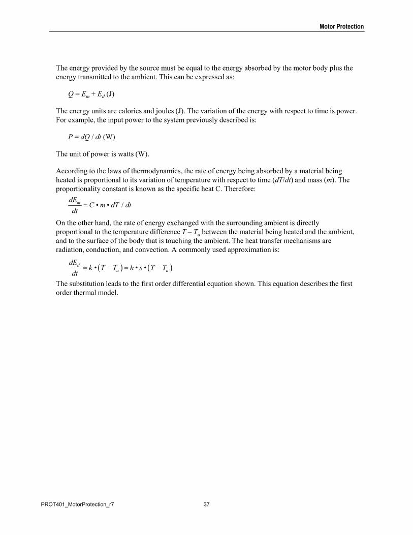
The energy provided by the source must be equal to the energy absorbed by the motor body plus the energy transmitted to the ambient. This can be expressed as:
Q = Em + Ed (J)
The energy units are calories and joules (J). The variation of the energy with respect to time is power. For example, the input power to the system previously described is:
P = dQ / dt (W)
The unit of power is watts (W).
According to the laws of thermodynamics, the rate of energy being absorbed by a material being heated is proportional to its variation of temperature with respect to time (dT/dt) and mass (m). The proportionality constant is known as the specific heat C. Therefore:
On the other hand, the rate of energy exchanged with the surrounding ambient is directly proportional to the temperature difference T – Ta between the material being heated and the ambient, and to the surface of the body that is touching the ambient. The heat transfer mechanisms are radiation, conduction, and convection. A commonly used approximation is:
The substitution leads to the first order differential equation shown. This equation describes the first order thermal model.
• • /mdEC m dT dt
dt
• • •da a
dEk T T h s T T
dt
37PROT401_MotorProtection_r7
Motor Protection
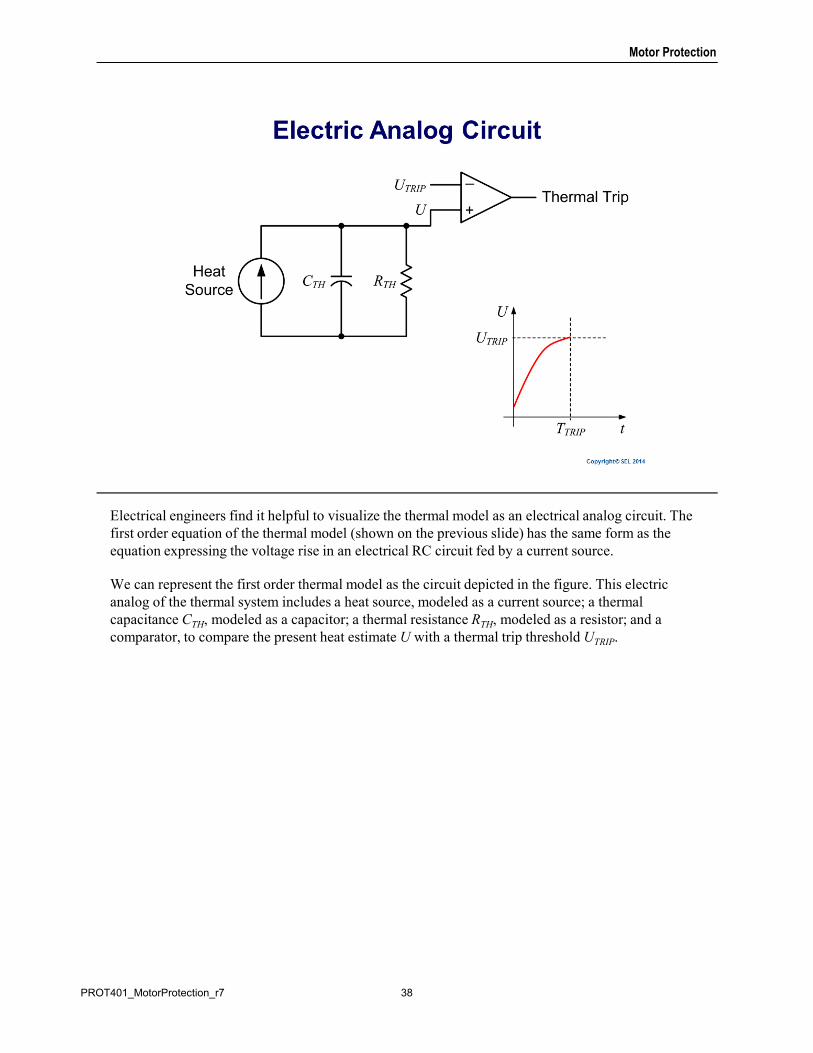
Electrical engineers find it helpful to visualize the thermal model as an electrical analog circuit. The first order equation of the thermal model (shown on the previous slide) has the same form as the equation expressing the voltage rise in an electrical RC circuit fed by a current source.
We can represent the first order thermal model as the circuit depicted in the figure. This electric analog of the thermal system includes a heat source, modeled as a current source; a thermal capacitance CTH, modeled as a capacitor; a thermal resistance RTH, modeled as a resistor; and a comparator, to compare the present heat estimate U with a thermal trip threshold UTRIP.
38PROT401_MotorProtection_r7
Motor Protection
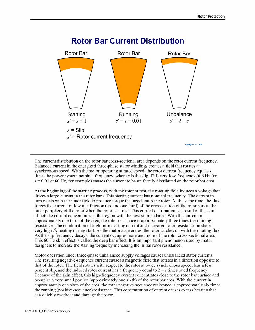
The current distribution on the rotor bar cross-sectional area depends on the rotor current frequency. Balanced current in the energized three-phase stator windings creates a field that rotates at synchronous speed. With the motor operating at rated speed, the rotor current frequency equals s times the power system nominal frequency, where s is the slip. This very low frequency (0.6 Hz for s = 0.01 at 60 Hz, for example) causes the current to be uniformly distributed on the rotor bar area.
At the beginning of the starting process, with the rotor at rest, the rotating field induces a voltage that drives a large current in the rotor bars. This starting current has nominal frequency. The current in turn reacts with the stator field to produce torque that accelerates the rotor. At the same time, the flux forces the current to flow in a fraction (around one third) of the cross section of the rotor bars at the outer periphery of the rotor when the rotor is at rest. This current distribution is a result of the skin effect: the current concentrates in the region with the lowest impedance. With the current in approximately one third of the area, the rotor resistance is approximately three times the running resistance. The combination of high rotor starting current and increased rotor resistance produces very high I2t heating during start. As the motor accelerates, the rotor catches up with the rotating flux. As the slip frequency decays, the current occupies more and more of the rotor cross-sectional area. This 60 Hz skin effect is called the deep bar effect. It is an important phenomenon used by motor designers to increase the starting torque by increasing the initial rotor resistance.
Motor operation under three-phase unbalanced supply voltages causes unbalanced stator currents. The resulting negative-sequence current causes a magnetic field that rotates in a direction opposite to that of the rotor. The field rotates with respect to the rotor at twice synchronous speed, less a few percent slip, and the induced rotor current has a frequency equal to 2 – s times rated frequency. Because of the skin effect, this high-frequency current concentrates close to the rotor bar surface and occupies a very small portion (approximately one sixth) of the rotor bar area. With the current in approximately one sixth of the area, the rotor negative-sequence resistance is approximately six times the running (positive-sequence) resistance. This concentration of current causes excess heating that can quickly overheat and damage the rotor.
39PROT401_MotorProtection_r7
Motor Protection
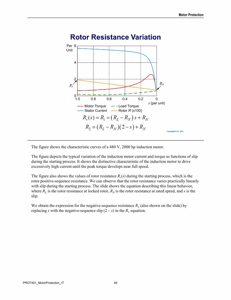
The figure shows the characteristic curves of a 480 V, 2000 hp induction motor.
The figure depicts the typical variation of the induction motor current and torque as functions of slip during the starting process. It shows the distinctive characteristic of the induction motor to drive excessively high current until the peak torque develops near full speed.
The figure also shows the values of rotor resistance Rr(s) during the starting process, which is the rotor positive-sequence resistance. We can observe that the rotor resistance varies practically linearly with slip during the starting process. The slide shows the equation describing this linear behavior, where RL is the rotor resistance at locked rotor, RN is the rotor resistance at rated speed, and s is the slip.
We obtain the expression for the negative-sequence resistance R2 (also shown on the slide) by replacing s with the negative-sequence slip (2 – s) in the R1 equation.
40PROT401_MotorProtection_r7
Motor Protection
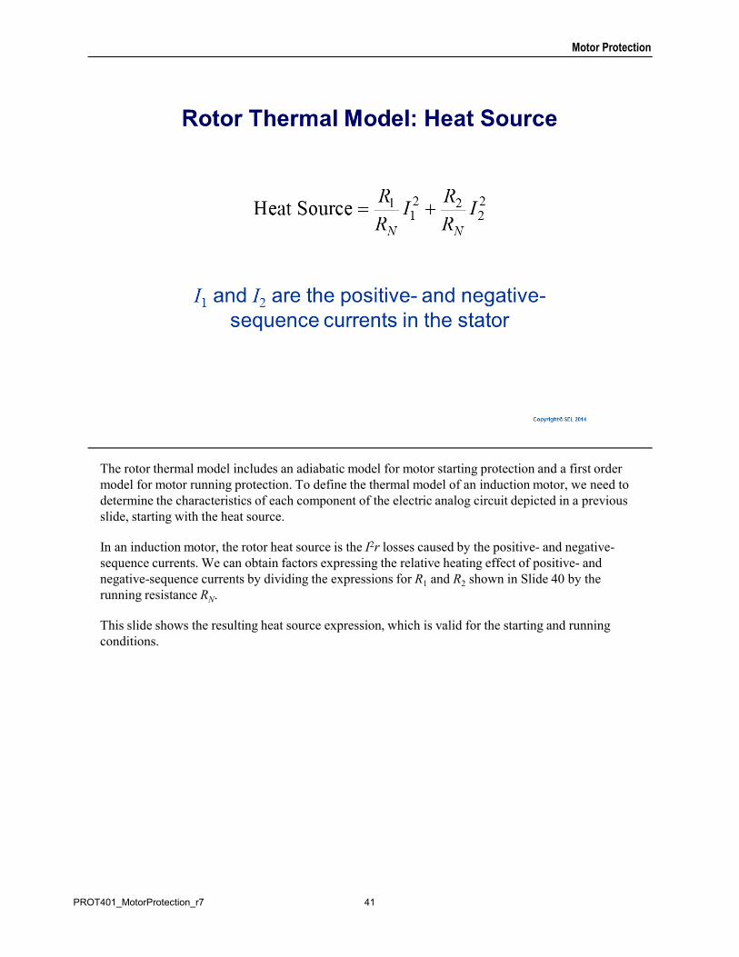
The rotor thermal model includes an adiabatic model for motor starting protection and a first order model for motor running protection. To define the thermal model of an induction motor, we need to determine the characteristics of each component of the electric analog circuit depicted in a previous slide, starting with the heat source.
In an induction motor, the rotor heat source is the I2r losses caused by the positive- and negative-sequence currents. We can obtain factors expressing the relative heating effect of positive- and negative-sequence currents by dividing the expressions for R1 and R2 shown in Slide 40 by the running resistance RN.
This slide shows the resulting heat source expression, which is valid for the starting and running conditions.
41PROT401_MotorProtection_r7
Motor Protection
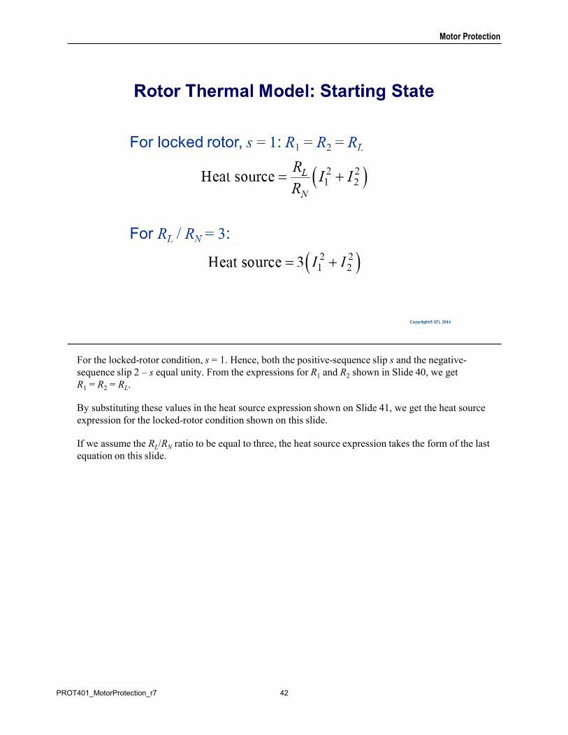
For the locked-rotor condition, s = 1. Hence, both the positive-sequence slip s and the negative-sequence slip 2 – s equal unity. From the expressions for R1 and R2 shown in Slide 40, we get R1 = R2 = RL.
By substituting these values in the heat source expression shown on Slide 41, we get the heat source expression for the locked-rotor condition shown on this slide.
If we assume the RL/RN ratio to be equal to three, the heat source expression takes the form of the last equation on this slide.
42PROT401_MotorProtection_r7
Motor Protection
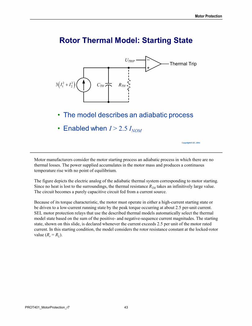
Motor manufacturers consider the motor starting process an adiabatic process in which there are no thermal losses. The power supplied accumulates in the motor mass and produces a continuous temperature rise with no point of equilibrium.
The figure depicts the electric analog of the adiabatic thermal system corresponding to motor starting. Since no heat is lost to the surroundings, the thermal resistance RTH takes an infinitively large value. The circuit becomes a purely capacitive circuit fed from a current source.
Because of its torque characteristic, the motor must operate in either a high-current starting state or be driven to a low-current running state by the peak torque occurring at about 2.5 per-unit current. SEL motor protection relays that use the described thermal models automatically select the thermal model state based on the sum of the positive- and negative-sequence current magnitudes. The starting state, shown on this slide, is declared whenever the current exceeds 2.5 per unit of the motor rated current. In this starting condition, the model considers the rotor resistance constant at the locked-rotor value (Rr = RL).
43PROT401_MotorProtection_r7
Motor Protection
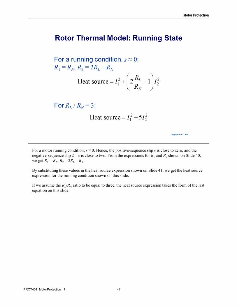
For a motor running condition, s ≈ 0. Hence, the positive-sequence slip s is close to zero, and the negative-sequence slip 2 – s is close to two. From the expressions for R1 and R2 shown on Slide 40, we get R1 = RN, R2 = 2RL – RN.
By substituting these values in the heat source expression shown on Slide 41, we get the heat source expression for the running condition shown on this slide.
If we assume the RL/RN ratio to be equal to three, the heat source expression takes the form of the last equation on this slide.
44PROT401_MotorProtection_r7
Motor Protection
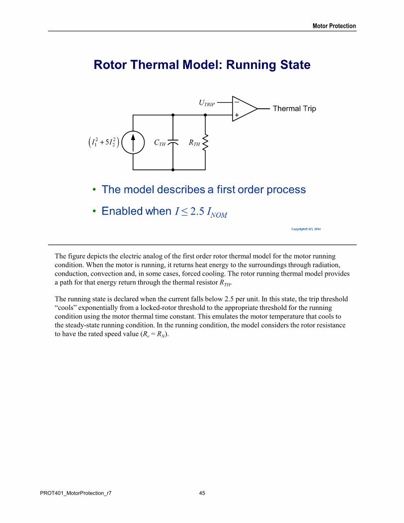
The figure depicts the electric analog of the first order rotor thermal model for the motor running condition. When the motor is running, it returns heat energy to the surroundings through radiation, conduction, convection and, in some cases, forced cooling. The rotor running thermal model provides a path for that energy return through the thermal resistor RTH.
The running state is declared when the current falls below 2.5 per unit. In this state, the trip threshold “cools” exponentially from a locked-rotor threshold to the appropriate threshold for the running condition using the motor thermal time constant. This emulates the motor temperature that cools to the steady-state running condition. In the running condition, the model considers the rotor resistance to have the rated speed value (Rr = RN).
45PROT401_MotorProtection_r7
Motor Protection
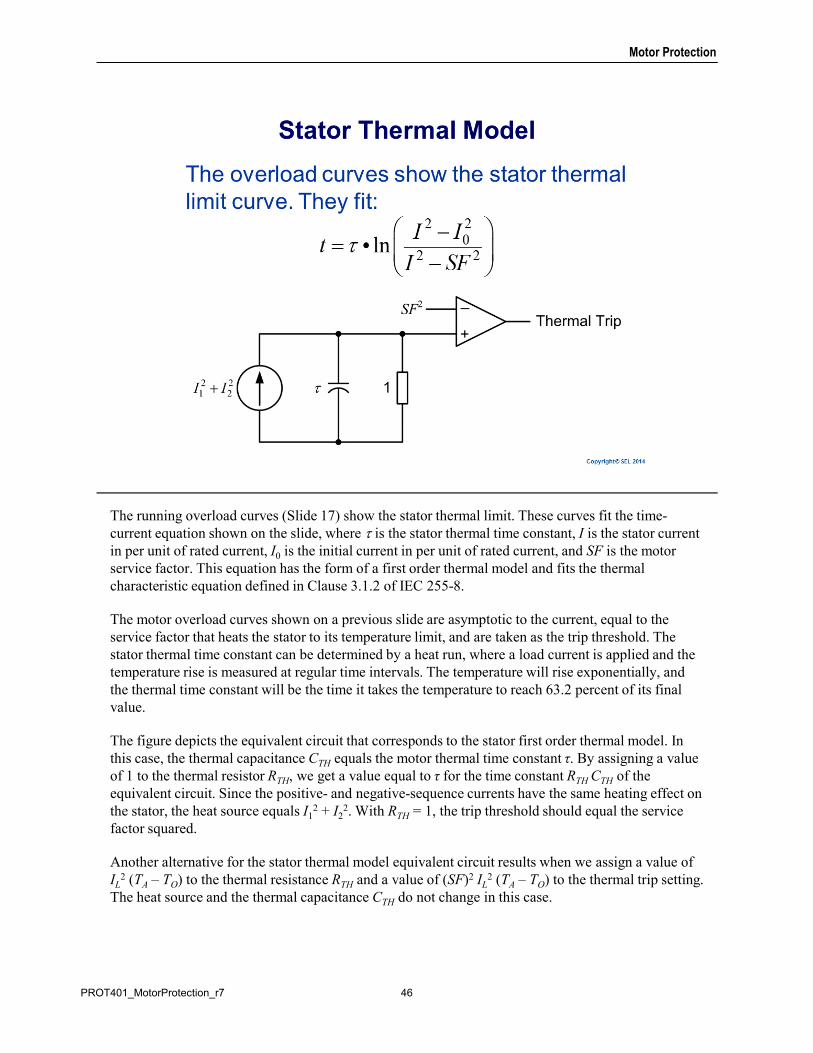
The running overload curves (Slide 17) show the stator thermal limit. These curves fit the time-current equation shown on the slide, where is the stator thermal time constant, I is the stator current in per unit of rated current, I0 is the initial current in per unit of rated current, and SF is the motor service factor. This equation has the form of a first order thermal model and fits the thermal characteristic equation defined in Clause 3.1.2 of IEC 255-8.
The motor overload curves shown on a previous slide are asymptotic to the current, equal to the service factor that heats the stator to its temperature limit, and are taken as the trip threshold. The stator thermal time constant can be determined by a heat run, where a load current is applied and the temperature rise is measured at regular time intervals. The temperature will rise exponentially, and the thermal time constant will be the time it takes the temperature to reach 63.2 percent of its final value.
The figure depicts the equivalent circuit that corresponds to the stator first order thermal model. In this case, the thermal capacitance CTH equals the motor thermal time constant τ. By assigning a value of 1 to the thermal resistor RTH, we get a value equal to τ for the time constant RTH CTH of the equivalent circuit. Since the positive- and negative-sequence currents have the same heating effect on the stator, the heat source equals I1
2 + I22. With RTH = 1, the trip threshold should equal the service
factor squared.
Another alternative for the stator thermal model equivalent circuit results when we assign a value of IL
2 (TA – TO) to the thermal resistance RTH and a value of (SF)2 IL2 (TA – TO) to the thermal trip setting.
The heat source and the thermal capacitance CTH do not change in this case.
46PROT401_MotorProtection_r7
Motor Protection
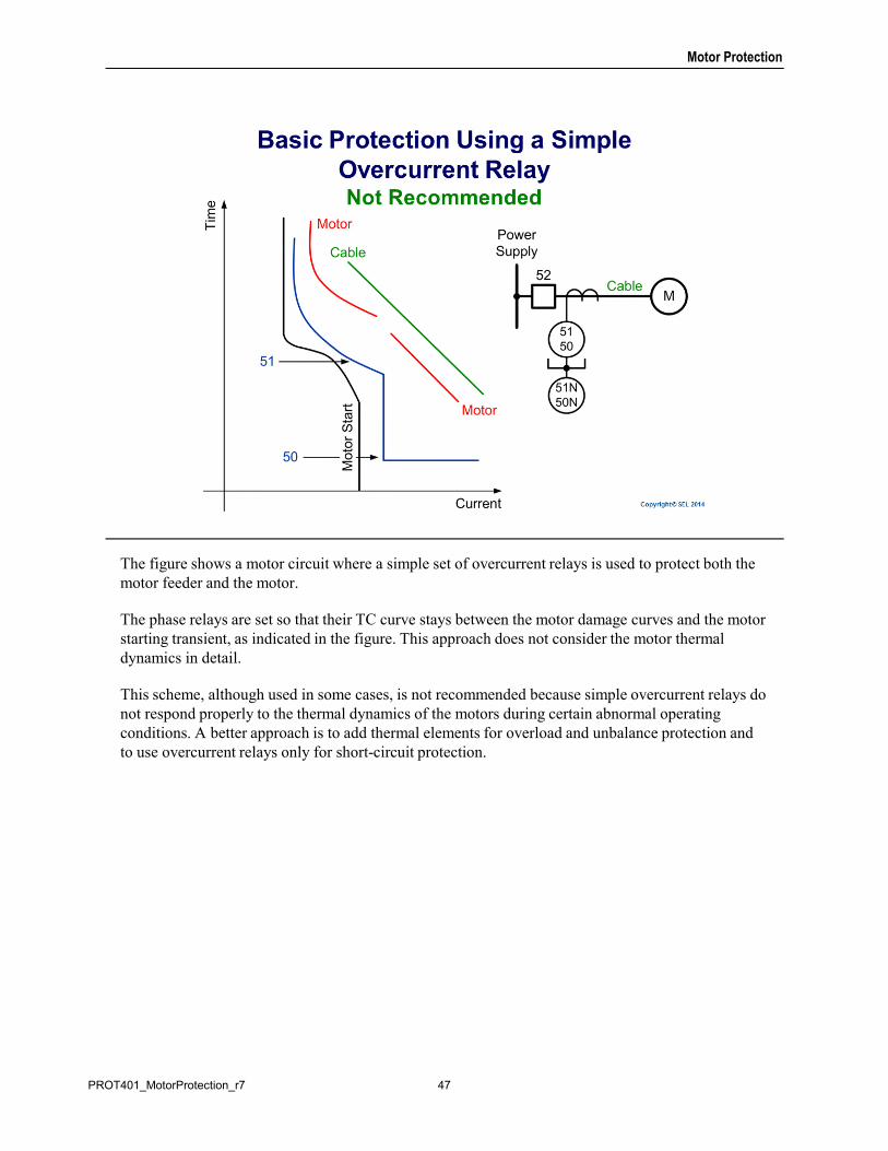
The figure shows a motor circuit where a simple set of overcurrent relays is used to protect both the motor feeder and the motor.
The phase relays are set so that their TC curve stays between the motor damage curves and the motor starting transient, as indicated in the figure. This approach does not consider the motor thermal dynamics in detail.
This scheme, although used in some cases, is not recommended because simple overcurrent relays do not respond properly to the thermal dynamics of the motors during certain abnormal operating conditions. A better approach is to add thermal elements for overload and unbalance protection and to use overcurrent relays only for short-circuit protection.
47PROT401_MotorProtection_r7
Motor Protection
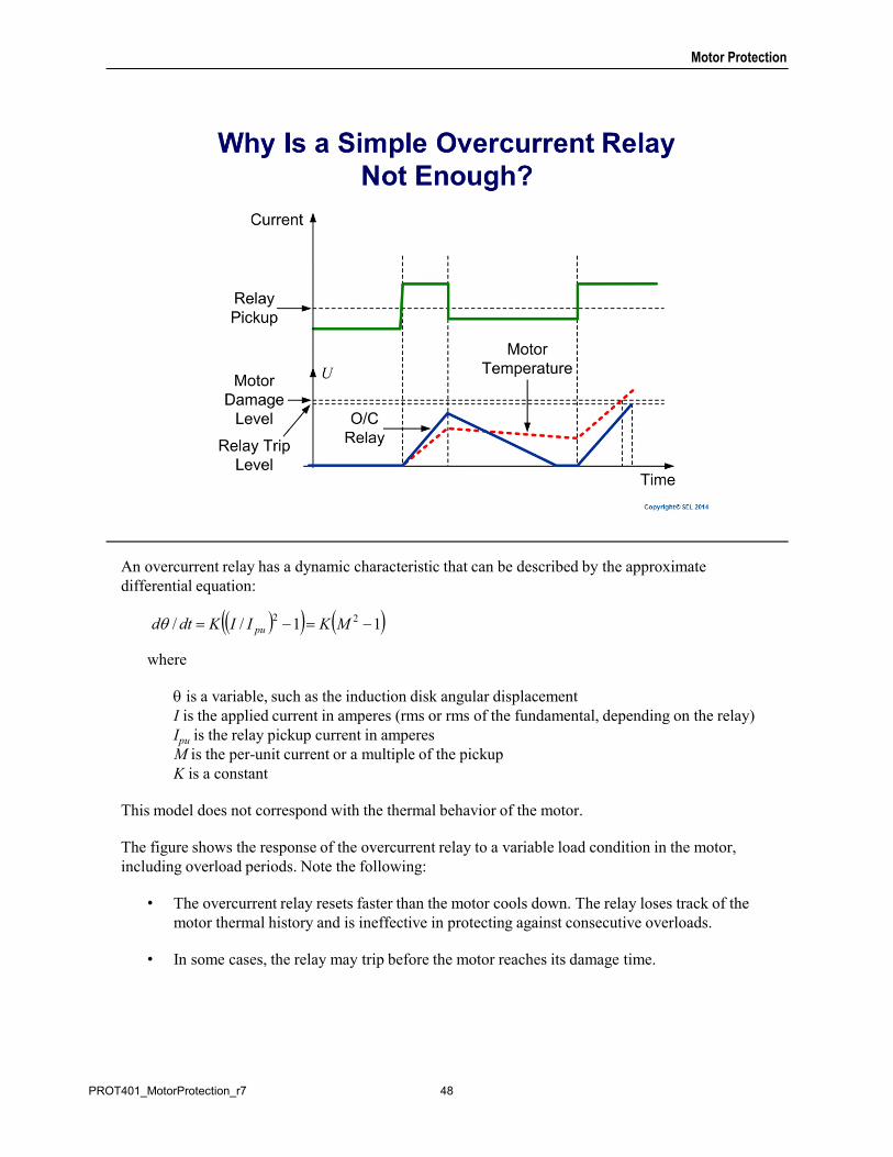
An overcurrent relay has a dynamic characteristic that can be described by the approximate differential equation:
where
is a variable, such as the induction disk angular displacementI is the applied current in amperes (rms or rms of the fundamental, depending on the relay)Ipu is the relay pickup current in amperesM is the per-unit current or a multiple of the pickupK is a constant
This model does not correspond with the thermal behavior of the motor.
The figure shows the response of the overcurrent relay to a variable load condition in the motor, including overload periods. Note the following:
• The overcurrent relay resets faster than the motor cools down. The relay loses track of the motor thermal history and is ineffective in protecting against consecutive overloads.
• In some cases, the relay may trip before the motor reaches its damage time.
11// 22 MKIIKdtd pu
48PROT401_MotorProtection_r7
Motor Protection
Motor short-circuit protection is needed to limit the damage caused by faults internal to the motor windings and in the leads in the motor zone of protection.
49PROT401_MotorProtection_r7
Motor Protection
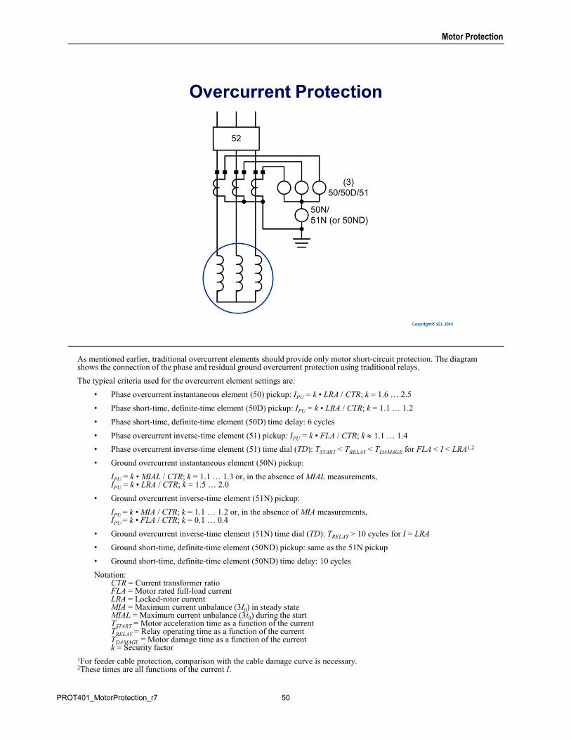
As mentioned earlier, traditional overcurrent elements should provide only motor short-circuit protection. The diagram shows the connection of the phase and residual ground overcurrent protection using traditional relays.
The typical criteria used for the overcurrent element settings are:
• Phase overcurrent instantaneous element (50) pickup: IPU = k • LRA / CTR; k = 1.6 … 2.5
• Phase short-time, definite-time element (50D) pickup: IPU = k • LRA / CTR; k = 1.1 … 1.2
• Phase short-time, definite-time element (50D) time delay: 6 cycles
• Phase overcurrent inverse-time element (51) pickup: IPU = k • FLA / CTR; k 1.1 … 1.4
• Phase overcurrent inverse-time element (51) time dial (TD): TSTART < TRELAY < TDAMAGE for FLA < I < LRA1,2
• Ground overcurrent instantaneous element (50N) pickup:
IPU = k • MIAL / CTR; k = 1.1 … 1.3 or, in the absence of MIAL measurements, IPU = k • LRA / CTR; k = 1.5 … 2.0
• Ground overcurrent inverse-time element (51N) pickup:
IPU = k • MIA / CTR; k = 1.1 … 1.2 or, in the absence of MIA measurements,IPU = k • FLA / CTR; k = 0.1 … 0.4
• Ground overcurrent inverse-time element (51N) time dial (TD): TRELAY > 10 cycles for I = LRA
• Ground short-time, definite-time element (50ND) pickup: same as the 51N pickup
• Ground short-time, definite-time element (50ND) time delay: 10 cycles
Notation:CTR = Current transformer ratioFLA = Motor rated full-load currentLRA = Locked-rotor currentMIA = Maximum current unbalance (3I0) in steady stateMIAL = Maximum current unbalance (3i0) during the startTSTART = Motor acceleration time as a function of the currentTRELAY = Relay operating time as a function of the currentTDAMAGE = Motor damage time as a function of the currentk = Security factor
1For feeder cable protection, comparison with the cable damage curve is necessary.2These times are all functions of the current I.
50PROT401_MotorProtection_r7
Motor Protection
Phase overcurrent protection is the most commonly used method for short-circuit protection.
Residual ground overcurrent relays use the sum of the phase currents to provide ground fault protection. This method is commonly used on effectively grounded systems where motors are installed.
The interrupting device must be rated to break fault current when using instantaneous elements.
51PROT401_MotorProtection_r7
Motor Protection
Phase overcurrent elements provide a degree of ground fault protection in effectively grounded systems. However, ground fault elements should be used for greater sensitivity because they are not affected by balanced load current and must be set above normal current unbalance.
Residual ground overcurrent elements measure the residual current on the secondary side of the same CTs used for the phase overcurrent elements. These CTs have a relatively high transformation ratio to account for the load currents, which limits ground fault protection sensitivity.
To improve sensitivity, you should use sensitive ground elements connected to the secondary of flux-summing CTs. These CTs can have a considerably lower current transformation ratio than phase CTs. A typical ratio is 50/5.
52PROT401_MotorProtection_r7
Motor Protection
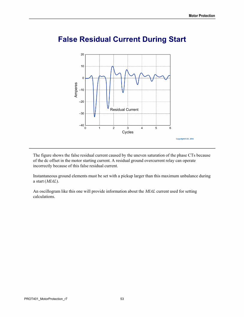
The figure shows the false residual current caused by the uneven saturation of the phase CTs because of the dc offset in the motor starting current. A residual ground overcurrent relay can operate incorrectly because of this false residual current.
Instantaneous ground elements must be set with a pickup larger than this maximum unbalance during a start (MIAL).
An oscillogram like this one will provide information about the MIAL current used for setting calculations.
53PROT401_MotorProtection_r7
Motor Protection
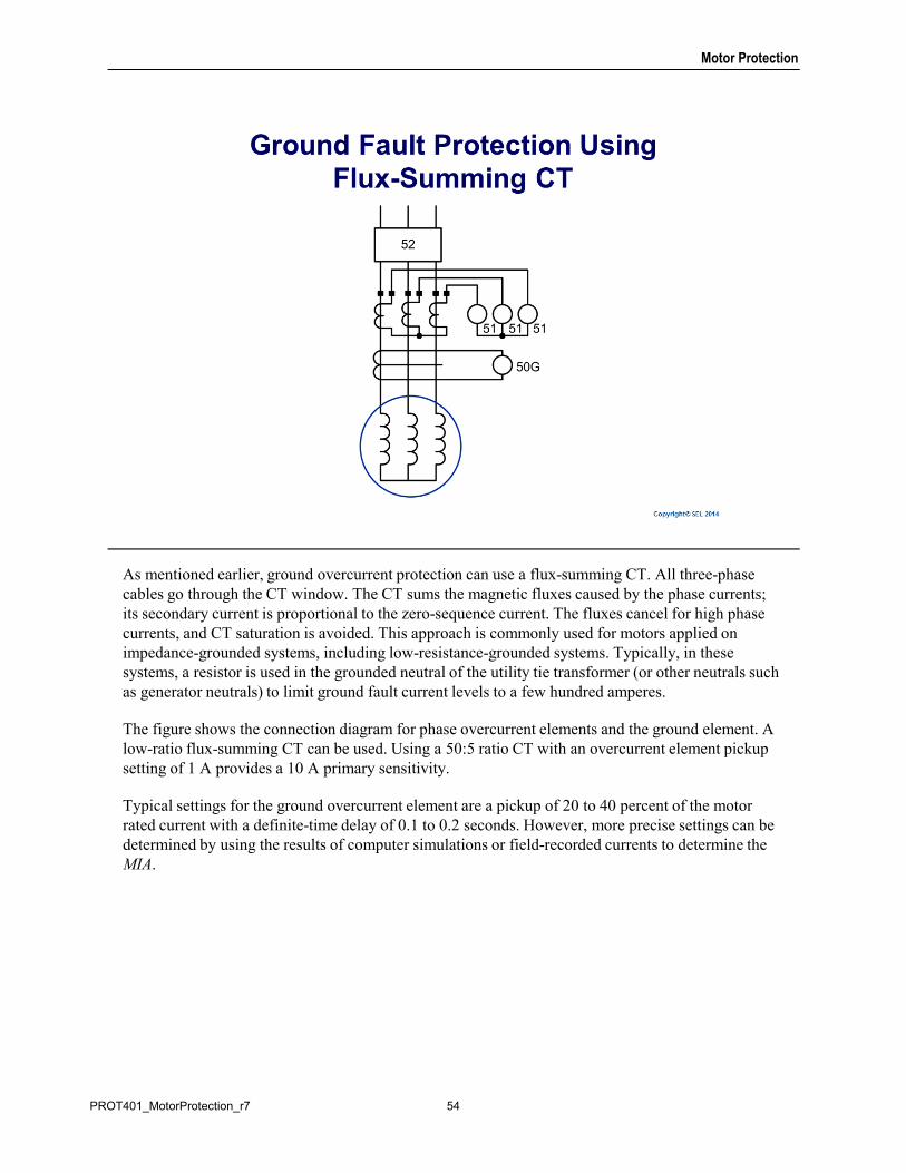
As mentioned earlier, ground overcurrent protection can use a flux-summing CT. All three-phase cables go through the CT window. The CT sums the magnetic fluxes caused by the phase currents; its secondary current is proportional to the zero-sequence current. The fluxes cancel for high phase currents, and CT saturation is avoided. This approach is commonly used for motors applied on impedance-grounded systems, including low-resistance-grounded systems. Typically, in these systems, a resistor is used in the grounded neutral of the utility tie transformer (or other neutrals such as generator neutrals) to limit ground fault current levels to a few hundred amperes.
The figure shows the connection diagram for phase overcurrent elements and the ground element. A low-ratio flux-summing CT can be used. Using a 50:5 ratio CT with an overcurrent element pickup setting of 1 A provides a 10 A primary sensitivity.
Typical settings for the ground overcurrent element are a pickup of 20 to 40 percent of the motor rated current with a definite-time delay of 0.1 to 0.2 seconds. However, more precise settings can be determined by using the results of computer simulations or field-recorded currents to determine the MIA.
54PROT401_MotorProtection_r7
Motor Protection
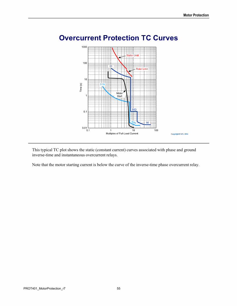
This typical TC plot shows the static (constant current) curves associated with phase and ground inverse-time and instantaneous overcurrent relays.
Note that the motor starting current is below the curve of the inverse-time phase overcurrent relay.
55PROT401_MotorProtection_r7
Motor Protection
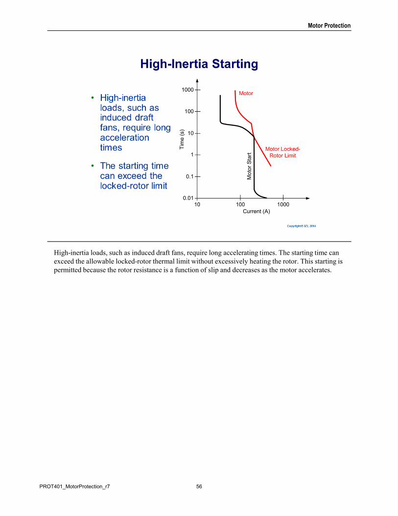
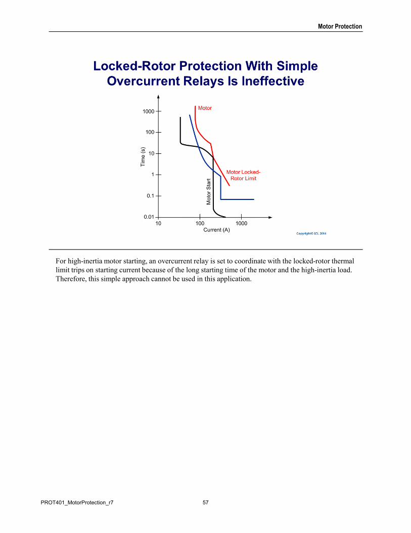
High-inertia loads, such as induced draft fans, require long accelerating times. The starting time can exceed the allowable locked-rotor thermal limit without excessively heating the rotor. This starting is permitted because the rotor resistance is a function of slip and decreases as the motor accelerates.
56PROT401_MotorProtection_r7
Motor Protection
For high-inertia motor starting, an overcurrent relay is set to coordinate with the locked-rotor thermal limit trips on starting current because of the long starting time of the motor and the high-inertia load. Therefore, this simple approach cannot be used in this application.
57PROT401_MotorProtection_r7
Motor Protection
Several approaches can be used when you are using traditional relays for these applications, such as:
• Include a motor zero-speed switch (Device 12) that supervises an additional overcurrent relay (Device 51 Start) set to protect the motor against a locked-rotor condition.
• Apply a distance mho-type relay (Device 21) to supervise the time-overcurrent relay Device 51 (Start).
• Use voltage and current measurements to calculate the slip. Use the slip values to determine the slip-dependent rotor resistance to be used in the rotor thermal model.
58PROT401_MotorProtection_r7
Motor Protection
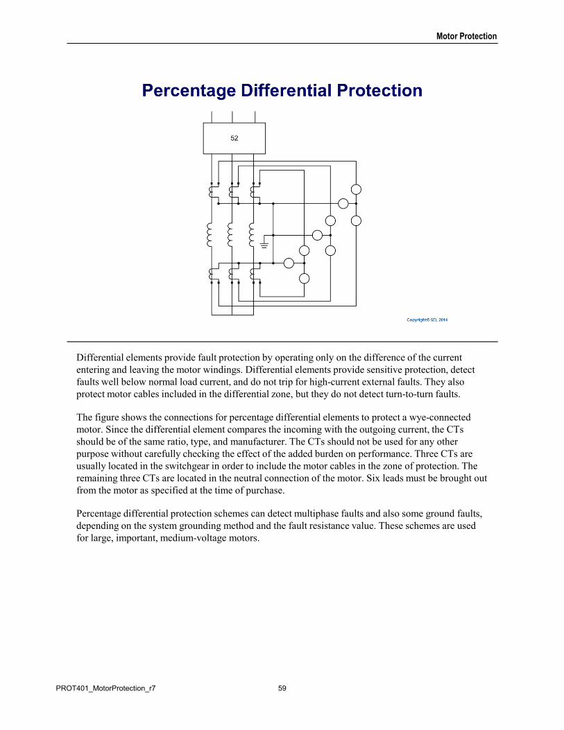
Differential elements provide fault protection by operating only on the difference of the current entering and leaving the motor windings. Differential elements provide sensitive protection, detect faults well below normal load current, and do not trip for high-current external faults. They also protect motor cables included in the differential zone, but they do not detect turn-to-turn faults.
The figure shows the connections for percentage differential elements to protect a wye-connected motor. Since the differential element compares the incoming with the outgoing current, the CTs should be of the same ratio, type, and manufacturer. The CTs should not be used for any other purpose without carefully checking the effect of the added burden on performance. Three CTs are usually located in the switchgear in order to include the motor cables in the zone of protection. The remaining three CTs are located in the neutral connection of the motor. Six leads must be brought out from the motor as specified at the time of purchase.
Percentage differential protection schemes can detect multiphase faults and also some ground faults, depending on the system grounding method and the fault resistance value. These schemes are used for large, important, medium-voltage motors.
59PROT401_MotorProtection_r7
Motor Protection
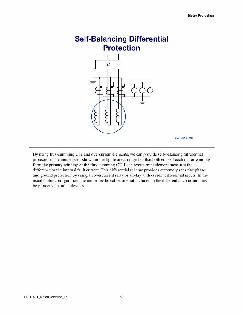
By using flux-summing CTs and overcurrent elements, we can provide self-balancing differential protection. The motor leads shown in the figure are arranged so that both ends of each motor winding form the primary winding of the flux-summing CT. Each overcurrent element measures the difference or the internal fault current. This differential scheme provides extremely sensitive phase and ground protection by using an overcurrent relay or a relay with current differential inputs. In the usual motor configuration, the motor feeder cables are not included in the differential zone and must be protected by other devices.
60PROT401_MotorProtection_r7
Motor Protection
Load loss and load jam are abnormal operating conditions that require detection and protection. For load loss, undercurrent or underpower are typically used with a time delay and the function is only armed once the motor is running. Load-jam protection is commonly provided with a definite-time overcurrent element. This function is armed only after the motor is running to allow for high starting currents. Load-jam conditions can also be detected by a well-designed motor thermal element; however, the specific load-jam protection trips faster than the thermal element.
During each start, the components of the induction motor (stator coil, rotor bars, and rotor end rings) are subjected to very high mechanical and electrical forces and thermal stresses due to the high value of the starting current and inadequate cooling. The cumulative effect of frequent starts can cause critical components’ temperatures to rise and exceed the design limits. This can result in damage to the rotor or insulation system. It is imperative that you limit the number of starts per hour to a safe value, recommended either by the manufacturer or by the NEMA MG 1 standard. A start counter is typically used to protect the motor from excessive starting.
In the previous discussion of thermal models, we found that the negative-sequence heating factor depends on the ratio of the locked-rotor resistance RL and the running resistance RN. During a motor running condition, for a typical RL/RN ratio of three, the heating factor of the negative-sequence current is five times that of the positive-sequence current. We can then see that any unbalance causes excessive heating and that an open phase in a running motor is the most severe case. When single phasing occurs, the negative-sequence current equals the positive-sequence current. At full load, the heating effect is that of a locked-rotor case.
(Continued on next slide)
61PROT401_MotorProtection_r7
Motor Protection
The running thermal model presented earlier accounts for the negative-sequence heating and provides unbalance protection under all operating conditions. However, some motor protection relays lack a thermal model. In other relays, the thermal model does not account for the negative-sequence rotor heating. In these cases, a separate negative-sequence overcurrent element should provide unbalanced current protection. A pickup setting of 3I2 = 1.5 A with a time delay of up to 4 seconds is a typical setting. You can also use this negative-sequence overcurrent element to complement a thermal element, which accounts for the negative-sequence heating.
Reverse rotation is caused by rolled phases on the motor. Typically, voltage-based detection and protection of the motor and driven equipment is provided for this abnormal condition.
In some applications, such as pumps, the head causes the motor pump to reverse direction after the motor is shut down. It is not desirable to restart the motor during this condition because excessive torques can be created that can damage the motor and driven equipment. A time delay is used to block a restart until after the motor and pump have stopped turning.
Motors in general are capable of operating at rated balanced load with a 10 percent variation from normal voltage. Because motors are in general constant kVA loads, current increases with decreasing voltage. In addition, torque decreases as a function of the voltage squared. Consequently, low voltage causes increased temperature and the possibility of stalling, in the worst case. In the case of a synchronous motor, the motor may not reach sufficient speed to enable it to pull into synchronism when the field is applied. Undervoltage elements with an appropriate time delay (to allow for the depressed voltage during starting and to override short duration disturbances) provide motor undervoltage protection. However, whether or not these protective elements are required depends upon the service that the protected motor is providing. A general approach is to trip nonessential motors on undervoltage to allow the voltage to recover and to keep the essential motors in operation.
62PROT401_MotorProtection_r7
Motor Protection
63PROT401_MotorProtection_r7

![IoT-ID: A novel device-specific identifier based on unique ... · Azure Sphere [14]. The objective of IoT-ID is to derive a &ORFN 2VFLOODWRU 'HYLFH 38),R7 'HYLFH $'&,R7 ,' Fig](https://img.pdfslide.us/doc/110x75/5ec6fd2b6455c21579108d51/iot-id-a-novel-device-speciic-identiier-based-on-unique-azure-sphere-14.jpg)


![(GJH &RJQLWLYH 6ROXWLRQV ZLWK 0LFURVRIW ,R7easdam.blob.core.windows.net/iotinaction...,r7 (gjh,r7 $]xuh 6skhuh26,r7:lqgrzv ,r7 /lqx[$]xuh,r7 (gjh &rpsdwleoh zlwk srsxodu rshudwlqj](https://img.pdfslide.us/doc/110x75/5f8df0458c541e24040c3752/gjh-rjqlwlyh-6roxwlrqv-zlwk-0lfurvriw-r7-gjhr7-xuh-6skhuh26r7lqgrzv.jpg)
![From Dvr to See Exploit of IoT Device...lsl.w r7, r7, #8 \x4f\xea\x07\x27 lsr.w r7, r7, #8 \x4f\xea\x17\x27 box\x00 push {r7} x80 xb4 ldr.w r7, [pc, #4] \xdf\xf8\x04\x70 b #6 \x01\xe0](https://img.pdfslide.us/doc/110x75/5f05e63e7e708231d41546e7/from-dvr-to-see-exploit-of-iot-device-lslw-r7-r7-8-x4fxeax07x27-lsrw.jpg)
![192 570101 : Catalogue detailing the Parker Ironcore ... · Motor Constant 7) [N/W] 5.8 8.2 Ironcore R7 Unit R7-1 R7-2 R7-3 Winding (Series/Parallel/Triple) S S P S T Power Supply](https://img.pdfslide.us/doc/110x75/6015a72694d45042b5755a57/192-570101-catalogue-detailing-the-parker-ironcore-motor-constant-7-nw.jpg)