Embed Size (px)
Citation preview
Component/ Fault Monitor Strategy Secondary MilSystem Code Description Malfunction Illum.
Transmission Control Module (TCM) P0601 Transmission Electro-Hydraulic
Control Module Read Only MemoryIncorrect program/calibrations
checksum = TRUE Boolean >= 5 Fail CountsOne Trip
DisableConditions:
MIL not Illuminated for DTC's:
Transmission Control Module (TCM) P0603
Transmission Electro-Hydraulic Control Module Long-Term Memory Reset
Non-volatile memory (static or dynamic) checksum failure at
Powerup= TRUE Boolean Runs
Continously
One Trip
DisableConditions:
MIL not Illuminated for DTC's:
Transmission Control Module (TCM) P0604
Transmission Electro-Hydraulic Control Module Random Access Memory
RAM Read/Write Failure (Single Word) = TRUE Boolean >= 5 Fail Counts
One Trip
= 16 Sample Counts
DisableConditions:
MIL not Illuminated for DTC's:
Transmission Control Module (TCM) P062F
Transmission Electro-Hydraulic Control Module Long Term Memory Performance
TCM Non-Volatile Memory bit Incorrect flag at Powerdown = TRUE Boolean Runs
Continously
One Trip
DisableConditions:
MIL not Illuminated for DTC's:
Transmission Control Module (TCM) P0634
Transmission Electro-Hydraulic Control Module Internal Temperature Too High
Fail Case 1Substrate Temperature >= 144 ºC >= 5 Fail Time (Sec)
One Trip
Fail Case 2 Substrate Temperature >= 50 ºC >= 2 Fail Time (Sec)
Ignition Voltage >= 18 VoltsNote: either fail case can set the
DTCIgnition Voltage Lo >= 9 VoltsIgnition Voltage Hi <= 31.99023 Volts
Substrate Temp Lo >= 0 ºCSubstrate Temp Hi <= 240 ºC
Substrate Temp Between Temp Range for Time >= 0.25 Sec
Malfunction Threshold Enable TimeCriteria Value Conditions Required
TCM: P0601
ECM: None
TCM: P0603
ECM: None
TCM: P0604
ECM: None
TCM: P062F
ECM: None
14 OBDG02 TCM Summary Tables (MH8/MHB)
TCM Section (MH8/MHB) Page 1 of 140
Component/ Fault Monitor Strategy Secondary MilSystem Code Description Malfunction Illum.
Malfunction Threshold Enable TimeCriteria Value Conditions Required
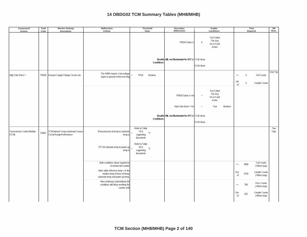
P0634 Status is
Test Failed This Key
On or Fault Active
DisableConditions:
MIL not Illuminated for DTC's:
High Side Driver 1 P0658 Actuator Supply Voltage Circuit Low The HWIO reports a low voltage (open or ground short) error flag = TRUE Boolean >= 4 Fail Counts
One Trip
outof 6 Sample Counts
P0658 Status is not =
Test Failed This Key
On or Fault Active
High Side Driver 1 On = True Boolean
DisableConditions:
MIL not Illuminated for DTC's:
Transmission Control Module (TCM) P0667 TCM Internal Temp (substrate) Sensor
Circuit Range/PerformanceIf transmission oil temp to substrate
temp >
Refer to Table 19 in
supportingdocuments
ºC
TwoTrips
If TCM substrate temp to power up temp >
Refer to Table 20 in
supportingdocuments
ºC
Both conditions above required to increment fail counter >= 3000 Fail Counts
(100ms loop)
Note: table reference temp = to the median temp of trans oil temp,
substrate temp and power up temp.
Outof 3750 Sample Counts
(100ms loop)
Non-continuous (intermittent) fail conditions will delay resetting fail
counter until>= 700 Pass Counts
(100ms loop)
Outof 875 Sample Counts
(100ms loop)
TCM: None
ECM: None
TCM: None
ECM: None
14 OBDG02 TCM Summary Tables (MH8/MHB)
TCM Section (MH8/MHB) Page 2 of 140
Component/ Fault Monitor Strategy Secondary MilSystem Code Description Malfunction Illum.
Malfunction Threshold Enable TimeCriteria Value Conditions Required
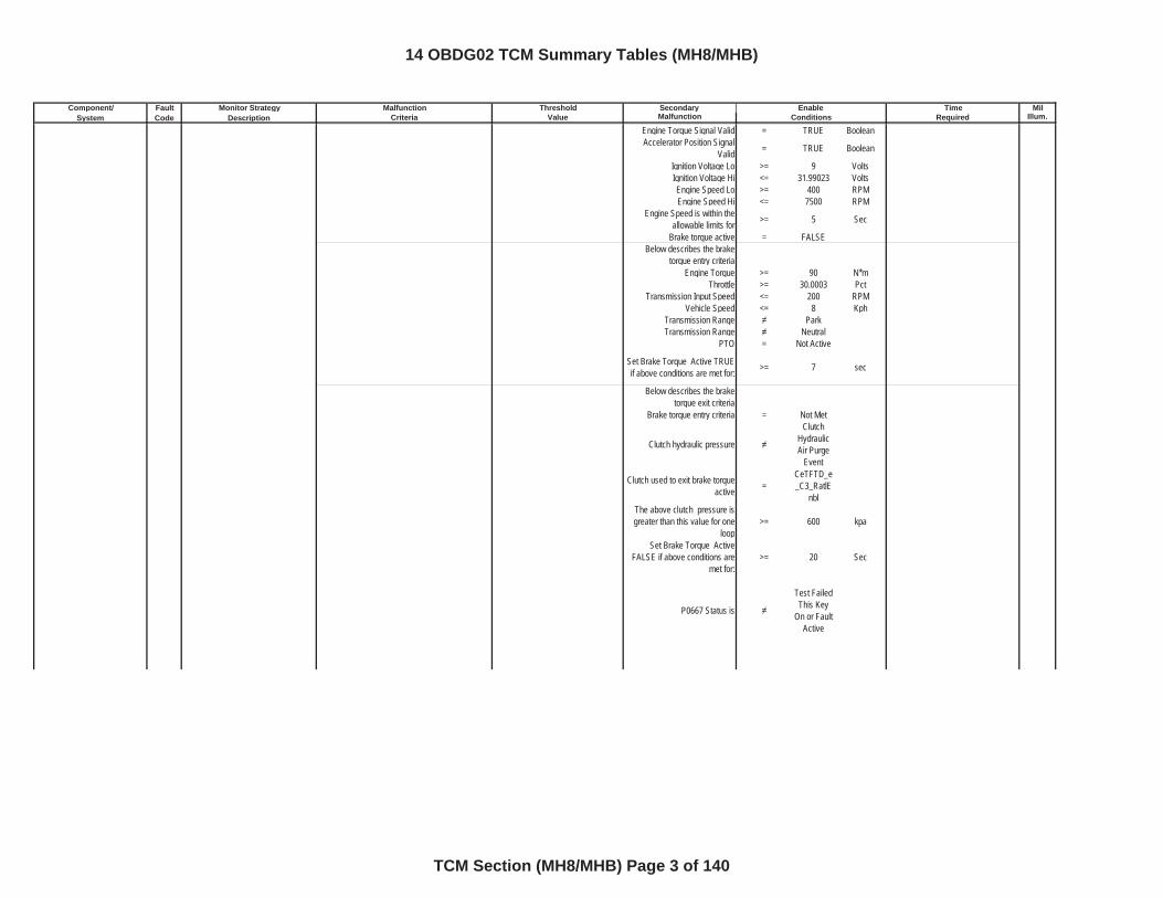
Engine Torque Signal Valid = TRUE BooleanAccelerator Position Signal
Valid = TRUE Boolean
Ignition Voltage Lo >= 9 VoltsIgnition Voltage Hi <= 31.99023 VoltsEngine Speed Lo >= 400 RPMEngine Speed Hi <= 7500 RPM
Engine Speed is within the allowable limits for >= 5 Sec
Brake torque active = FALSEBelow describes the brake
torque entry criteriaEngine Torque >= 90 N*m
Throttle >= 30.0003 PctTransmission Input Speed <= 200 RPM
Vehicle Speed <= 8 KphTransmission Range ParkTransmission Range Neutral
PTO = Not Active
Set Brake Torque Active TRUE if above conditions are met for: >= 7 sec
Below describes the brake torque exit criteria
Brake torque entry criteria = Not Met
Clutch hydraulic pressure
Clutch Hydraulic Air Purge
Event
Clutch used to exit brake torque active =
CeTFTD_e_C3_RatlE
nblThe above clutch pressure is greater than this value for one
loop>= 600 kpa
Set Brake Torque Active FALSE if above conditions are
met for:>= 20 Sec
P0667 Status is
Test Failed This Key
On or Fault Active
14 OBDG02 TCM Summary Tables (MH8/MHB)
TCM Section (MH8/MHB) Page 3 of 140
Component/ Fault Monitor Strategy Secondary MilSystem Code Description Malfunction Illum.
Malfunction Threshold Enable TimeCriteria Value Conditions Required
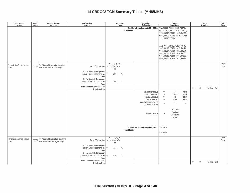
DisableConditions:
MIL not Illuminated for DTC's:
Transmission Control Module (TCM) P0668 TCM internal temperature (substrate)
thermistor failed at a low voltge Type of Sensor Used =CeTFTI_e_VoltageInversePr
op
TwoTrips
If TCM Substrate Temperature Sensor = Direct Proportional and
Temp<= 254 ºC
If TCM Substrate Temperature Sensor = Indirect Proportional and
Temp>= 254 ºC
Either condition above will satisfy the fail conditions >= 60 Fail Timer (Sec)
Ignition Voltage Lo >= 9 VoltsIgnition Voltage Hi <= 31.99023 VoltsEngine Speed Lo >= 400 RPMEngine Speed Hi <= 7500 RPM
Engine Speed is within the allowable limits for >= 5 Sec
P0668 Status is
Test Failed This Key
On or Fault Active
DisableConditions:
MIL not Illuminated for DTC's:
Transmission Control Module (TCM) P0669 TCM internal temperature (substrate)
thermistor failed at a high voltage Type of Sensor Used =CeTFTI_e_VoltageInversePr
op
TwoTrips
If TCM Substrate Temperature Sensor = Direct Proportional and
Temp>= -254 ºC
If TCM Substrate Temperature Sensor = Indirect Proportional and
Temp<= -254 ºC
Either condition above will satisfy the fail conditions >= 60 Fail Timer (Sec)
TCM: P0658, P0668, P0669, P06AD, P06AE, P0716, P0712, P0713, P0717, P0722, P0723, P0962, P0963, P0966, P0967, P0970, P0971, P215C, P2720, P2721, P2729, P2730
ECM: P0101, P0102, P0103, P0106, P0107, P0108, P0171, P0172, P0174, P0175, P0201, P0202, P0203, P0204, P0205, P0206, P0207, P0208, P0300, P0301, P0302, P0303, P0304, P0305, P0306, P0307, P0308, P0401, P042E
TCM: None
ECM: None
14 OBDG02 TCM Summary Tables (MH8/MHB)
TCM Section (MH8/MHB) Page 4 of 140
Component/ Fault Monitor Strategy Secondary MilSystem Code Description Malfunction Illum.
Malfunction Threshold Enable TimeCriteria Value Conditions Required
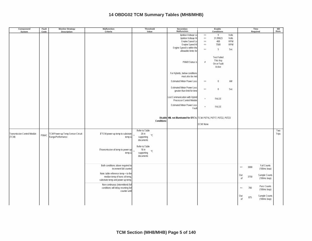
Ignition Voltage Lo >= 9 VoltsIgnition Voltage Hi <= 31.99023 VoltsEngine Speed Lo >= 400 RPMEngine Speed Hi <= 7500 RPM
Engine Speed is within the allowable limits for >= 5 Sec
P0669 Status is
Test Failed This Key
On or Fault Active
For Hybrids, below conditions must also be met
Estimated Motor Power Loss >= 0 kW
Estimated Motor Power Loss greater than limit for time >= 0 Sec
Lost Communication with Hybrid Processor Control Module = FALSE
Estimated Motor Power Loss Fault = FALSE
DisableConditions:
MIL not Illuminated for DTC's:
Transmission Control Module (TCM) P06AC TCM Power-up Temp Sensor Circuit
Range/PerformanceIf TCM power-up temp to substrate
temp >
Refer to Table 20 in
supportingdocuments
ºC
TwoTrips
If transmission oil temp to power up temp >
Refer to Table 18 in
supportingdocuments
ºC
Both conditions above required to increment fail counter >= 3000 Fail Counts
(100ms loop)
Note: table reference temp = to the median temp of trans oil temp,
substrate temp and power up temp.
Outof 3750 Sample Counts
(100ms loop)
Non-continuous (intermittent) fail conditions will delay resetting fail
counter until>= 700 Pass Counts
(100ms loop)
Outof 875 Sample Counts
(100ms loop)
TCM: P0716, P0717, P0722, P0723
ECM: None
14 OBDG02 TCM Summary Tables (MH8/MHB)
TCM Section (MH8/MHB) Page 5 of 140
Component/ Fault Monitor Strategy Secondary MilSystem Code Description Malfunction Illum.
Malfunction Threshold Enable TimeCriteria Value Conditions Required
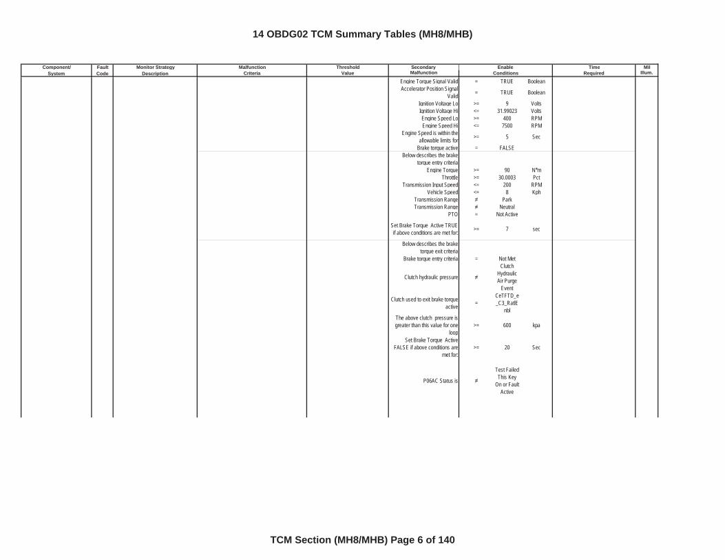
Engine Torque Signal Valid = TRUE BooleanAccelerator Position Signal
Valid = TRUE Boolean
Ignition Voltage Lo >= 9 VoltsIgnition Voltage Hi <= 31.99023 VoltsEngine Speed Lo >= 400 RPMEngine Speed Hi <= 7500 RPM
Engine Speed is within the allowable limits for >= 5 Sec
Brake torque active = FALSEBelow describes the brake
torque entry criteriaEngine Torque >= 90 N*m
Throttle >= 30.0003 PctTransmission Input Speed <= 200 RPM
Vehicle Speed <= 8 KphTransmission Range ParkTransmission Range Neutral
PTO = Not Active
Set Brake Torque Active TRUE if above conditions are met for: >= 7 sec
Below describes the brake torque exit criteria
Brake torque entry criteria = Not Met
Clutch hydraulic pressure
Clutch Hydraulic Air Purge
Event
Clutch used to exit brake torque active =
CeTFTD_e_C3_RatlE
nblThe above clutch pressure is greater than this value for one
loop>= 600 kpa
Set Brake Torque Active FALSE if above conditions are
met for:>= 20 Sec
P06AC Status is
Test Failed This Key
On or Fault Active
14 OBDG02 TCM Summary Tables (MH8/MHB)
TCM Section (MH8/MHB) Page 6 of 140
Component/ Fault Monitor Strategy Secondary MilSystem Code Description Malfunction Illum.
Malfunction Threshold Enable TimeCriteria Value Conditions Required
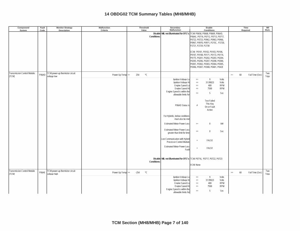
DisableConditions:
MIL not Illuminated for DTC's:
Transmission Control Module (TCM) P06AD TCM power-up thermistor circuit
voltage low Power Up Temp <= 254 ºC >= 60 Fail Time (Sec) TwoTrips
Ignition Voltage Lo >= 9 VoltsIgnition Voltage Hi <= 31.99023 VoltsEngine Speed Lo >= 400 RPMEngine Speed Hi <= 7500 RPM
Engine Speed is within the allowable limits for >= 5 Sec
P06AD Status is
Test Failed This Key
On or Fault Active
For Hybrids, below conditions must also be met
Estimated Motor Power Loss >= 0 kW
Estimated Motor Power Loss greater than limit for time >= 0 Sec
Lost Communication with Hybrid Processor Control Module = FALSE
Estimated Motor Power Loss Fault = FALSE
DisableConditions:
MIL not Illuminated for DTC's:
Transmission Control Module (TCM) P06AE TCM power-up thermistor circuit
voltage high Power Up Temp >= -254 ºC >= 60 Fail Time (Sec) TwoTrips
Ignition Voltage Lo >= 9 VoltsIgnition Voltage Hi <= 31.99023 VoltsEngine Speed Lo >= 400 RPMEngine Speed Hi <= 7500 RPM
Engine Speed is within the allowable limits for >= 5 Sec
TCM: P0658, P0668, P0669, P06AD, P06AE, P0716, P0712, P0713, P0717, P0722, P0723, P0962, P0963, P0966, P0967, P0970, P0971, P215C, P2720, P2721, P2729, P2730
ECM: P0101, P0102, P0103, P0106, P0107, P0108, P0171, P0172, P0174, P0175, P0201, P0202, P0203, P0204, P0205, P0206, P0207, P0208, P0300, P0301, P0302, P0303, P0304, P0305, P0306, P0307, P0308, P0401, P042E
TCM: P0716, P0717, P0722, P0723
ECM: None
14 OBDG02 TCM Summary Tables (MH8/MHB)
TCM Section (MH8/MHB) Page 7 of 140
Component/ Fault Monitor Strategy Secondary MilSystem Code Description Malfunction Illum.
Malfunction Threshold Enable TimeCriteria Value Conditions Required
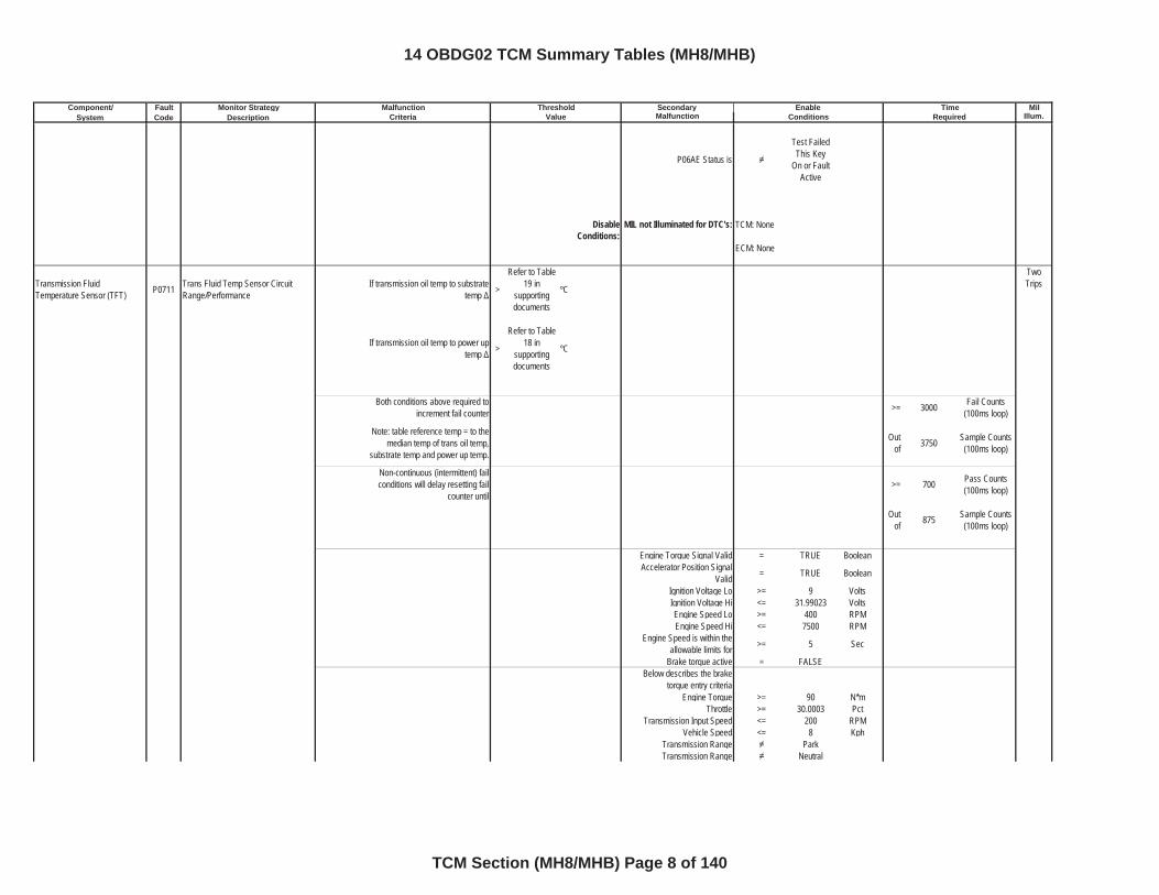
P06AE Status is
Test Failed This Key
On or Fault Active
DisableConditions:
MIL not Illuminated for DTC's:
Transmission Fluid Temperature Sensor (TFT) P0711 Trans Fluid Temp Sensor Circuit
Range/PerformanceIf transmission oil temp to substrate
temp >
Refer to Table 19 in
supportingdocuments
ºC
TwoTrips
If transmission oil temp to power up temp >
Refer to Table 18 in
supportingdocuments
ºC
Both conditions above required to increment fail counter >= 3000 Fail Counts
(100ms loop)
Note: table reference temp = to the median temp of trans oil temp,
substrate temp and power up temp.
Outof 3750 Sample Counts
(100ms loop)
Non-continuous (intermittent) fail conditions will delay resetting fail
counter until>= 700 Pass Counts
(100ms loop)
Outof 875 Sample Counts
(100ms loop)
Engine Torque Signal Valid = TRUE BooleanAccelerator Position Signal
Valid = TRUE Boolean
Ignition Voltage Lo >= 9 VoltsIgnition Voltage Hi <= 31.99023 VoltsEngine Speed Lo >= 400 RPMEngine Speed Hi <= 7500 RPM
Engine Speed is within the allowable limits for >= 5 Sec
Brake torque active = FALSEBelow describes the brake
torque entry criteriaEngine Torque >= 90 N*m
Throttle >= 30.0003 PctTransmission Input Speed <= 200 RPM
Vehicle Speed <= 8 KphTransmission Range ParkTransmission Range Neutral
TCM: None
ECM: None
14 OBDG02 TCM Summary Tables (MH8/MHB)
TCM Section (MH8/MHB) Page 8 of 140
Component/ Fault Monitor Strategy Secondary MilSystem Code Description Malfunction Illum.
Malfunction Threshold Enable TimeCriteria Value Conditions Required
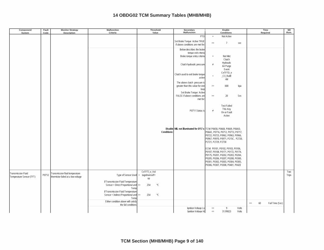
PTO = Not Active
Set Brake Torque Active TRUE if above conditions are met for: >= 7 sec
Below describes the brake torque exit criteria
Brake torque entry criteria = Not Met
Clutch hydraulic pressure
Clutch Hydraulic Air Purge
Event
Clutch used to exit brake torque active =
CeTFTD_e_C3_RatlE
nblThe above clutch pressure is greater than this value for one
loop>= 600 kpa
Set Brake Torque Active FALSE if above conditions are
met for:>= 20 Sec
P0711 Status is
Test Failed This Key
On or Fault Active
DisableConditions:
MIL not Illuminated for DTC's:
Transmission Fluid Temperature Sensor (TFT) P0712 Transmission fluid temperature
thermistor failed at a low voltage Type of Sensor Used =CeTFTI_e_VoltageInversePr
op
TwoTrips
If Transmission Fluid Temperature Sensor = Direct Proportional and
Temp<= 254 ºC
If Transmission Fluid Temperature Sensor = Indirect Proportional and
Temp>= 254 ºC
Either condition above will satisfy the fail conditions >= 60 Fail Time (Sec)
Ignition Voltage Lo >= 9 VoltsIgnition Voltage Hi <= 31.99023 Volts
TCM: P0658, P0668, P0669, P06AD, P06AE, P0716, P0712, P0713, P0717, P0722, P0723, P0962, P0963, P0966, P0967, P0970, P0971, P215C, P2720, P2721, P2729, P2730
ECM: P0101, P0102, P0103, P0106, P0107, P0108, P0171, P0172, P0174, P0175, P0201, P0202, P0203, P0204, P0205, P0206, P0207, P0208, P0300, P0301, P0302, P0303, P0304, P0305, P0306, P0307, P0308, P0401, P042E
14 OBDG02 TCM Summary Tables (MH8/MHB)
TCM Section (MH8/MHB) Page 9 of 140
Component/ Fault Monitor Strategy Secondary MilSystem Code Description Malfunction Illum.
Malfunction Threshold Enable TimeCriteria Value Conditions Required
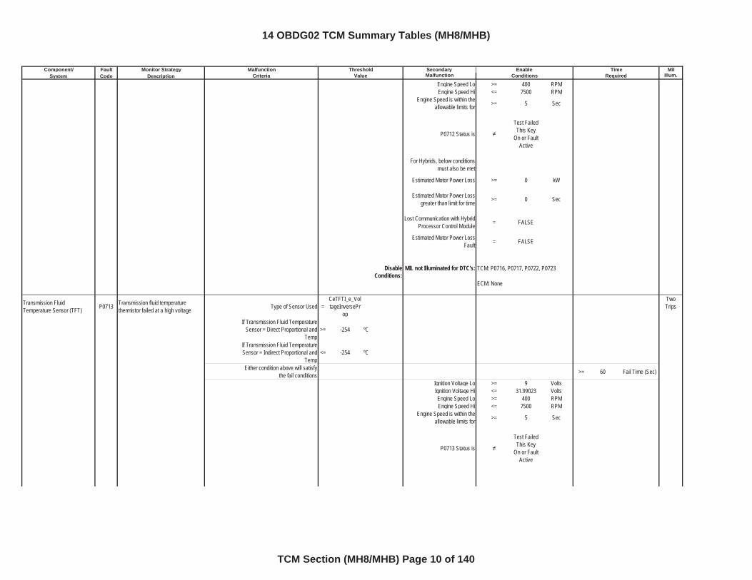
Engine Speed Lo >= 400 RPMEngine Speed Hi <= 7500 RPM
Engine Speed is within the allowable limits for >= 5 Sec
P0712 Status is
Test Failed This Key
On or Fault Active
For Hybrids, below conditions must also be met
Estimated Motor Power Loss >= 0 kW
Estimated Motor Power Loss greater than limit for time >= 0 Sec
Lost Communication with Hybrid Processor Control Module = FALSE
Estimated Motor Power Loss Fault = FALSE
DisableConditions:
MIL not Illuminated for DTC's:
Transmission Fluid Temperature Sensor (TFT) P0713 Transmission fluid temperature
thermistor failed at a high voltage Type of Sensor Used =CeTFTI_e_VoltageInversePr
op
TwoTrips
If Transmission Fluid Temperature Sensor = Direct Proportional and
Temp>= -254 ºC
If Transmission Fluid Temperature Sensor = Indirect Proportional and
Temp<= -254 ºC
Either condition above will satisfy the fail conditions >= 60 Fail Time (Sec)
Ignition Voltage Lo >= 9 VoltsIgnition Voltage Hi <= 31.99023 VoltsEngine Speed Lo >= 400 RPMEngine Speed Hi <= 7500 RPM
Engine Speed is within the allowable limits for >= 5 Sec
P0713 Status is
Test Failed This Key
On or Fault Active
TCM: P0716, P0717, P0722, P0723
ECM: None
14 OBDG02 TCM Summary Tables (MH8/MHB)
TCM Section (MH8/MHB) Page 10 of 140
Component/ Fault Monitor Strategy Secondary MilSystem Code Description Malfunction Illum.
Malfunction Threshold Enable TimeCriteria Value Conditions Required
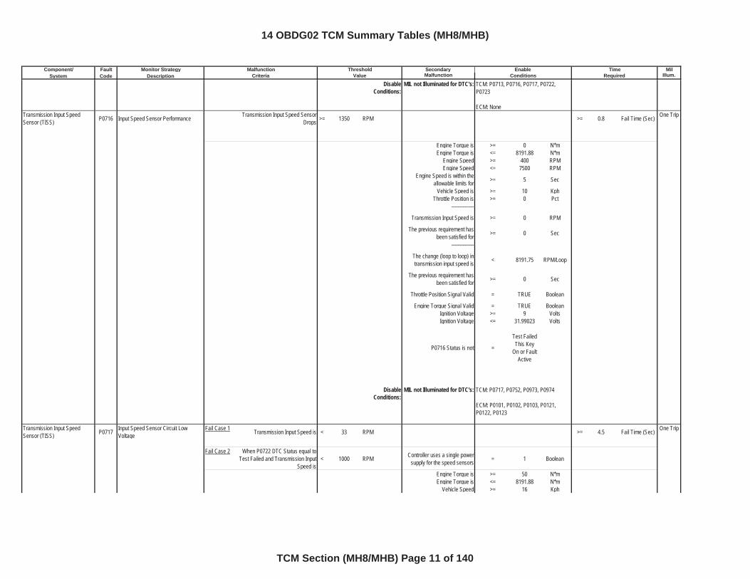
DisableConditions:
MIL not Illuminated for DTC's:
Transmission Input Speed Sensor (TISS) P0716 Input Speed Sensor Performance Transmission Input Speed Sensor
Drops >= 1350 RPM >= 0.8 Fail Time (Sec) One Trip
Engine Torque is >= 0 N*mEngine Torque is <= 8191.88 N*m
Engine Speed >= 400 RPMEngine Speed <= 7500 RPM
Engine Speed is within the allowable limits for >= 5 Sec
Vehicle Speed is >= 10 KphThrottle Position is >= 0 Pct
--------------
Transmission Input Speed is >= 0 RPM
The previous requirement has been satisfied for >= 0 Sec
--------------
The change (loop to loop) in transmission input speed is < 8191.75 RPM/Loop
The previous requirement has been satisfied for >= 0 Sec
Throttle Position Signal Valid = TRUE Boolean
Engine Torque Signal Valid = TRUE BooleanIgnition Voltage >= 9 VoltsIgnition Voltage <= 31.99023 Volts
P0716 Status is not =
Test Failed This Key
On or Fault Active
DisableConditions:
MIL not Illuminated for DTC's:
Transmission Input Speed Sensor (TISS) P0717 Input Speed Sensor Circuit Low
VoltageFail Case 1 Transmission Input Speed is < 33 RPM >= 4.5 Fail Time (Sec) One Trip
Fail Case 2 When P0722 DTC Status equal to Test Failed and Transmission Input
Speed is< 1000 RPM Controller uses a single power
supply for the speed sensors = 1 Boolean
Engine Torque is >= 50 N*mEngine Torque is <= 8191.88 N*m
Vehicle Speed >= 16 Kph
TCM: P0713, P0716, P0717, P0722, P0723
ECM: None
TCM: P0717, P0752, P0973, P0974
ECM: P0101, P0102, P0103, P0121, P0122, P0123
14 OBDG02 TCM Summary Tables (MH8/MHB)
TCM Section (MH8/MHB) Page 11 of 140
Component/ Fault Monitor Strategy Secondary MilSystem Code Description Malfunction Illum.
Malfunction Threshold Enable TimeCriteria Value Conditions Required
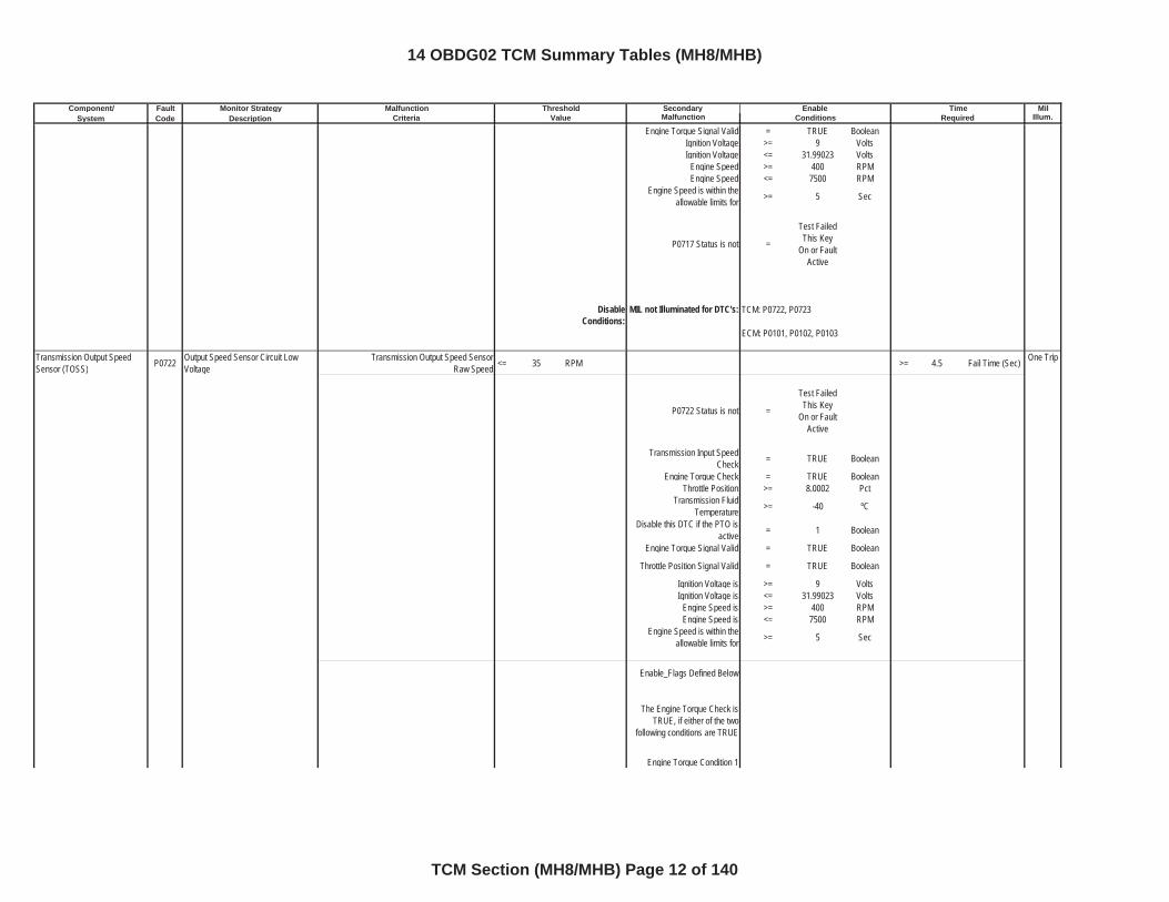
Engine Torque Signal Valid = TRUE BooleanIgnition Voltage >= 9 VoltsIgnition Voltage <= 31.99023 Volts
Engine Speed >= 400 RPMEngine Speed <= 7500 RPM
Engine Speed is within the allowable limits for >= 5 Sec
P0717 Status is not =
Test Failed This Key
On or Fault Active
DisableConditions:
MIL not Illuminated for DTC's:
Transmission Output Speed Sensor (TOSS) P0722 Output Speed Sensor Circuit Low
VoltageTransmission Output Speed Sensor
Raw Speed <= 35 RPM >= 4.5 Fail Time (Sec) One Trip
P0722 Status is not =
Test Failed This Key
On or Fault Active
Transmission Input Speed Check = TRUE Boolean
Engine Torque Check = TRUE BooleanThrottle Position >= 8.0002 Pct
Transmission Fluid Temperature >= -40 ºC
Disable this DTC if the PTO is active = 1 Boolean
Engine Torque Signal Valid = TRUE Boolean
Throttle Position Signal Valid = TRUE Boolean
Ignition Voltage is >= 9 VoltsIgnition Voltage is <= 31.99023 Volts
Engine Speed is >= 400 RPMEngine Speed is <= 7500 RPM
Engine Speed is within the allowable limits for >= 5 Sec
Enable_Flags Defined Below
The Engine Torque Check is TRUE, if either of the two
following conditions are TRUE
Engine Torque Condition 1
TCM: P0722, P0723
ECM: P0101, P0102, P0103
14 OBDG02 TCM Summary Tables (MH8/MHB)
TCM Section (MH8/MHB) Page 12 of 140
Component/ Fault Monitor Strategy Secondary MilSystem Code Description Malfunction Illum.
Malfunction Threshold Enable TimeCriteria Value Conditions Required
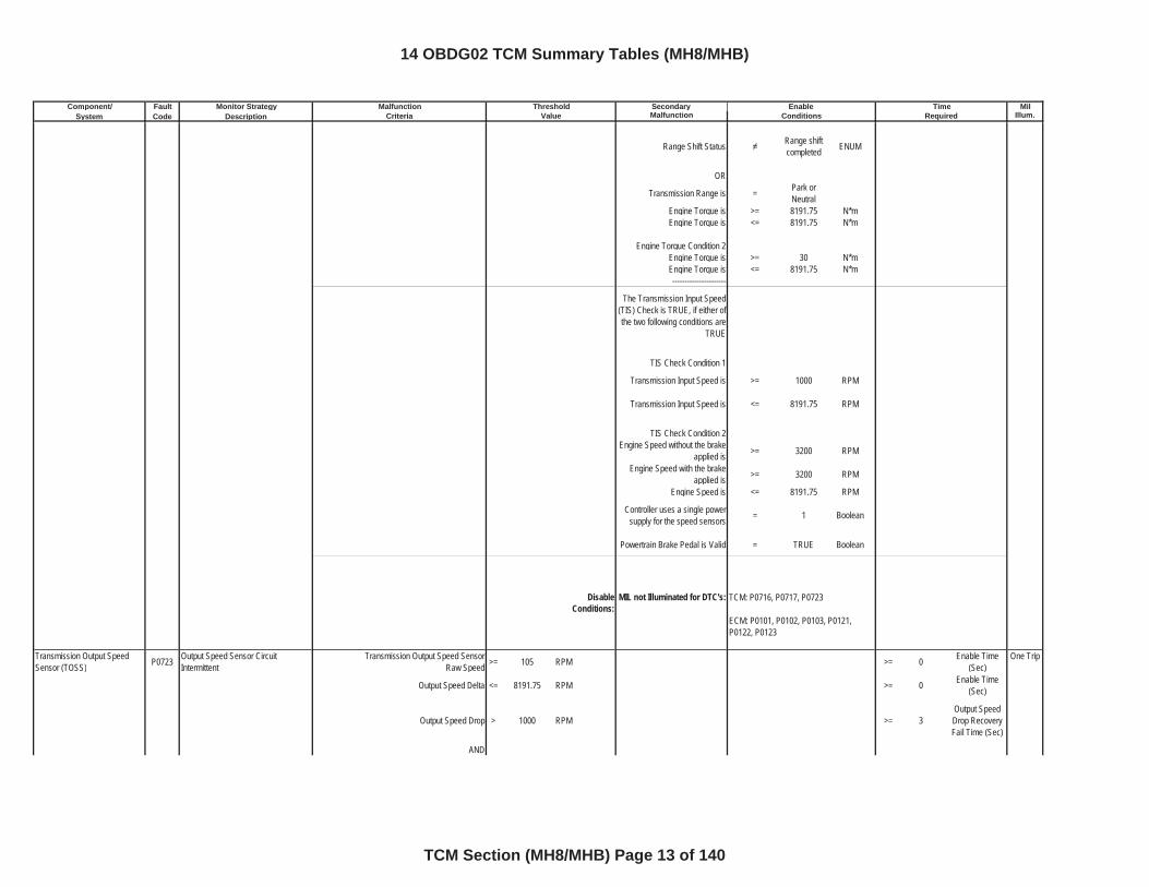
Range Shift Status Range shift completed ENUM
OR
Transmission Range is = Park or Neutral
Engine Torque is >= 8191.75 N*mEngine Torque is <= 8191.75 N*m
Engine Torque Condition 2Engine Torque is >= 30 N*mEngine Torque is <= 8191.75 N*m----------------------
The Transmission Input Speed (TIS) Check is TRUE, if either of the two following conditions are
TRUE
TIS Check Condition 1
Transmission Input Speed is >= 1000 RPM
Transmission Input Speed is <= 8191.75 RPM
TIS Check Condition 2Engine Speed without the brake
applied is >= 3200 RPM
Engine Speed with the brake applied is >= 3200 RPM
Engine Speed is <= 8191.75 RPM
Controller uses a single power supply for the speed sensors = 1 Boolean
Powertrain Brake Pedal is Valid = TRUE Boolean
DisableConditions:
MIL not Illuminated for DTC's:
Transmission Output Speed Sensor (TOSS) P0723 Output Speed Sensor Circuit
IntermittentTransmission Output Speed Sensor
Raw Speed >= 105 RPM >= 0 Enable Time (Sec)
One Trip
Output Speed Delta <= 8191.75 RPM >= 0 Enable Time (Sec)
Output Speed Drop > 1000 RPM >= 3Output Speed Drop Recovery Fail Time (Sec)
AND
TCM: P0716, P0717, P0723
ECM: P0101, P0102, P0103, P0121, P0122, P0123
14 OBDG02 TCM Summary Tables (MH8/MHB)
TCM Section (MH8/MHB) Page 13 of 140
Component/ Fault Monitor Strategy Secondary MilSystem Code Description Malfunction Illum.
Malfunction Threshold Enable TimeCriteria Value Conditions Required
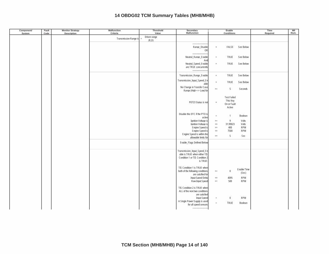
Transmission Range is = Driven range (R,D)
----------------------Range_Disable = FALSE See Below
OR----------------------
Neutral_Range_Enable = TRUE See BelowAnd
Neutral_Speed_Enable = TRUE See Beloware TRUE concurrently
----------------------
Transmission_Range_Enable = TRUE See Below
Transmission_Input_Speed_Enable = TRUE See Below
No Change in Transfer Case Range (High <-> Low) for >= 5 Seconds
P0723 Status is not =
Test Failed This Key
On or Fault Active
Disable this DTC if the PTO is active = 1 Boolean
Ignition Voltage is >= 9 VoltsIgnition Voltage is <= 31.99023 Volts
Engine Speed is >= 400 RPMEngine Speed is <= 7500 RPM
Engine Speed is within the allowable limits for >= 5 Sec
Enable_Flags Defined Below
Transmission_Input_Speed_Enable is TRUE when either TIS Condition 1 or TIS Condition 2
is TRUE:
TIS Condition 1 is TRUE when both of the following conditions
are satsified for >= 0 Enable Time
(Sec)
Input Speed Delta <= 4095 RPMRaw Input Speed >= 500 RPM
TIS Condition 2 is TRUE when ALL of the next two conditions
are satisfiedInput Speed = 0 RPM
A Single Power Supply is used for all speed sensors = TRUE Boolean
----------------------
14 OBDG02 TCM Summary Tables (MH8/MHB)
TCM Section (MH8/MHB) Page 14 of 140
Component/ Fault Monitor Strategy Secondary MilSystem Code Description Malfunction Illum.
Malfunction Threshold Enable TimeCriteria Value Conditions Required
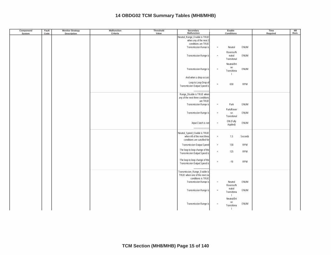
Neutral_Range_Enable is TRUE when any of the next 3
conditions are TRUETransmission Range is = Neutral ENUM
Transmission Range is =Reverse/N
eutralTransitonal
ENUM
Transmission Range is =
Neutral/Drive
Transitional
ENUM
And when a drop occurs
Loop to Loop Drop of Transmission Output Speed is > 650 RPM
----------------------Range_Disable is TRUE when
any of the next three conditions are TRUE
Transmission Range is = Park ENUM
Transmission Range is =Park/Rever
seTransitonal
ENUM
Input Clutch is not = ON (Fully Applied) ENUM
----------------------
Neutral_Speed_Enable is TRUE when All of the next three
conditions are satsified for > 1.5 Seconds
Transmission Output Speed > 130 RPM
The loop to loop change of the Transmission Output Speed is < 125 RPM
The loop to loop change of the Transmission Output Speed is > -10 RPM
----------------------Transmission_Range_Enable is TRUE when one of the next six
conditions is TRUETransmission Range is = Neutral ENUM
Transmission Range is =
Reverse/Neutral
Transitional
ENUM
Transmission Range is =
Neutral/Drive
Transitional
ENUM
14 OBDG02 TCM Summary Tables (MH8/MHB)
TCM Section (MH8/MHB) Page 15 of 140
Component/ Fault Monitor Strategy Secondary MilSystem Code Description Malfunction Illum.
Malfunction Threshold Enable TimeCriteria Value Conditions Required
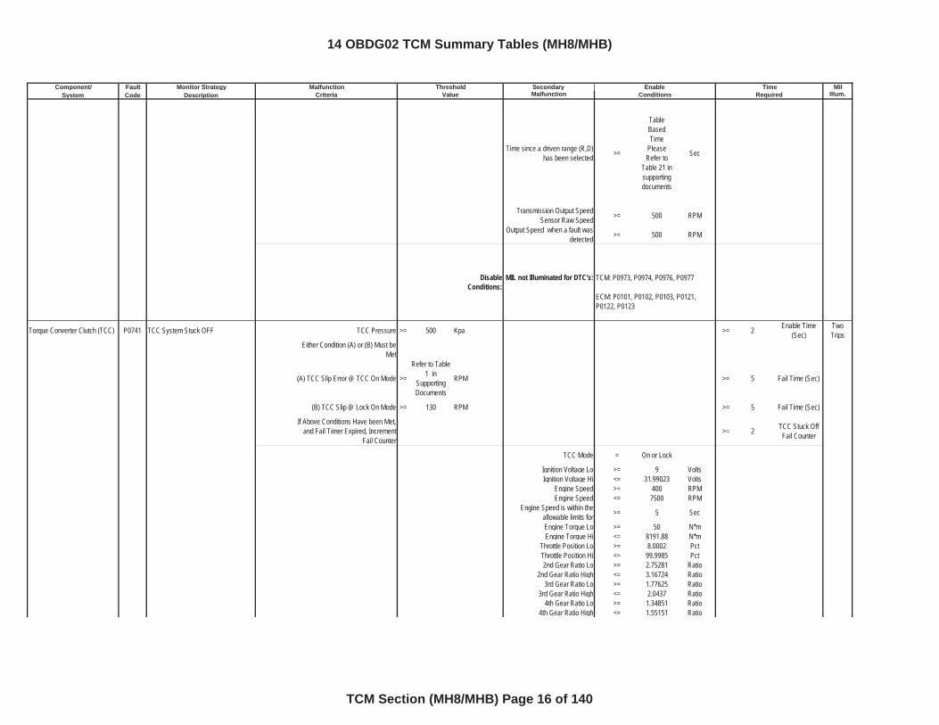
Time since a driven range (R,D) has been selected >=
Table BasedTime
Please Refer to
Table 21 in supportingdocuments
Sec
Transmission Output Speed Sensor Raw Speed >= 500 RPM
Output Speed when a fault was detected >= 500 RPM
DisableConditions:
MIL not Illuminated for DTC's:
Torque Converter Clutch (TCC) P0741 TCC System Stuck OFF TCC Pressure >= 500 Kpa >= 2 Enable Time (Sec)
TwoTrips
Either Condition (A) or (B) Must be Met
(A) TCC Slip Error @ TCC On Mode >=
Refer to Table 1 in
SupportingDocuments
RPM >= 5 Fail Time (Sec)
(B) TCC Slip @ Lock On Mode >= 130 RPM >= 5 Fail Time (Sec)
If Above Conditions Have been Met, and Fail Timer Expired, Increment
Fail Counter>= 2 TCC Stuck Off
Fail Counter
TCC Mode = On or Lock
Ignition Voltage Lo >= 9 VoltsIgnition Voltage Hi <= 31.99023 Volts
Engine Speed >= 400 RPMEngine Speed <= 7500 RPM
Engine Speed is within the allowable limits for >= 5 Sec
Engine Torque Lo >= 50 N*mEngine Torque Hi <= 8191.88 N*m
Throttle Position Lo >= 8.0002 PctThrottle Position Hi <= 99.9985 Pct2nd Gear Ratio Lo >= 2.75281 Ratio
2nd Gear Ratio High <= 3.16724 Ratio3rd Gear Ratio Lo >= 1.77625 Ratio
3rd Gear Ratio High <= 2.0437 Ratio4th Gear Ratio Lo >= 1.34851 Ratio
4th Gear Ratio High <= 1.55151 Ratio
TCM: P0973, P0974, P0976, P0977
ECM: P0101, P0102, P0103, P0121, P0122, P0123
14 OBDG02 TCM Summary Tables (MH8/MHB)
TCM Section (MH8/MHB) Page 16 of 140
Component/ Fault Monitor Strategy Secondary MilSystem Code Description Malfunction Illum.
Malfunction Threshold Enable TimeCriteria Value Conditions Required
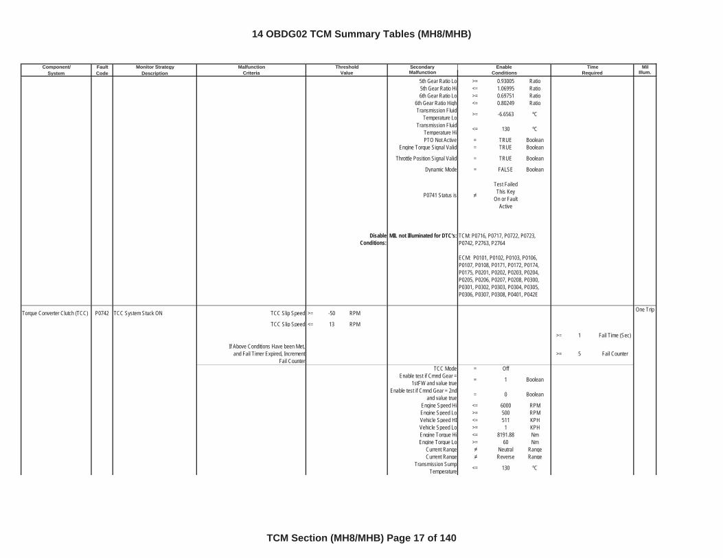
5th Gear Ratio Lo >= 0.93005 Ratio5th Gear Ratio Hi <= 1.06995 Ratio6th Gear Ratio Lo >= 0.69751 Ratio
6th Gear Ratio High <= 0.80249 RatioTransmission Fluid
Temperature Lo >= -6.6563 ºC
Transmission Fluid Temperature Hi <= 130 ºC
PTO Not Active = TRUE BooleanEngine Torque Signal Valid = TRUE Boolean
Throttle Position Signal Valid = TRUE Boolean
Dynamic Mode = FALSE Boolean
P0741 Status is
Test Failed This Key
On or Fault Active
DisableConditions:
MIL not Illuminated for DTC's:
Torque Converter Clutch (TCC) P0742 TCC System Stuck ON TCC Slip Speed >= -50 RPM One Trip
TCC Slip Speed <= 13 RPM
>= 1 Fail Time (Sec)
If Above Conditions Have been Met, and Fail Timer Expired, Increment
Fail Counter>= 5 Fail Counter
TCC Mode = OffEnable test if Cmnd Gear =
1stFW and value true = 1 Boolean
Enable test if Cmnd Gear = 2nd and value true = 0 Boolean
Engine Speed Hi <= 6000 RPMEngine Speed Lo >= 500 RPMVehicle Speed HI <= 511 KPHVehicle Speed Lo >= 1 KPHEngine Torque Hi <= 8191.88 NmEngine Torque Lo >= 60 Nm
Current Range Neutral RangeCurrent Range Reverse Range
Transmission Sump Temperature <= 130 ºC
TCM: P0716, P0717, P0722, P0723,P0742, P2763, P2764
ECM: P0101, P0102, P0103, P0106, P0107, P0108, P0171, P0172, P0174, P0175, P0201, P0202, P0203, P0204, P0205, P0206, P0207, P0208, P0300, P0301, P0302, P0303, P0304, P0305, P0306, P0307, P0308, P0401, P042E
14 OBDG02 TCM Summary Tables (MH8/MHB)
TCM Section (MH8/MHB) Page 17 of 140
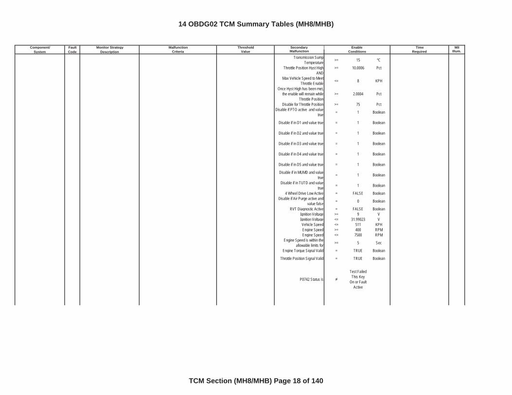
Component/ Fault Monitor Strategy Secondary MilSystem Code Description Malfunction Illum.
Malfunction Threshold Enable TimeCriteria Value Conditions Required
Transmission Sump Temperature >= 15 ºC
Throttle Position Hyst High >= 10.0006 PctAND
Max Vehicle Speed to Meet Throttle Enable <= 8 KPH
Once Hyst High has been met, the enable will remain while
Throttle Position>= 2.0004 Pct
Disable for Throttle Position >= 75 PctDisable if PTO active and value
true = 1 Boolean
Disable if in D1 and value true = 1 Boolean
Disable if in D2 and value true = 1 Boolean
Disable if in D3 and value true = 1 Boolean
Disable if in D4 and value true = 1 Boolean
Disable if in D5 and value true = 1 Boolean
Disable if in MUMD and value true = 1 Boolean
Disable if in TUTD and value true = 1 Boolean
4 Wheel Drive Low Active = FALSE BooleanDisable if Air Purge active and
value false = 0 Boolean
RVT Diagnostic Active = FALSE BooleanIgnition Voltage >= 9 VIgnition Voltage <= 31.99023 VVehicle Speed <= 511 KPHEngine Speed >= 400 RPMEngine Speed <= 7500 RPM
Engine Speed is within the allowable limits for >= 5 Sec
Engine Torque Signal Valid = TRUE Boolean
Throttle Position Signal Valid = TRUE Boolean
P0742 Status is
Test Failed This Key
On or Fault Active
14 OBDG02 TCM Summary Tables (MH8/MHB)
TCM Section (MH8/MHB) Page 18 of 140
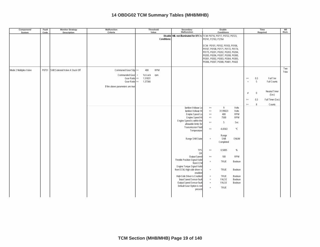
Component/ Fault Monitor Strategy Secondary MilSystem Code Description Malfunction Illum.
Malfunction Threshold Enable TimeCriteria Value Conditions Required
DisableConditions:
MIL not Illuminated for DTC's:
Mode 2 Multiplex Valve P0751 Shift Solenoid Valve A Stuck Off Commaned Gear Slip >= 400 RPM TwoTrips
Commanded Gear = 1st Lock rpmGear Ratio <= 1.51831 >= 0.3 Fail TmrGear Ratio >= 1.37366 = 5 Fail Counts
If the above parameters are true
0 Neutral Timer (Sec)
>= 0.3 Fail Timer (Sec)
>= 8 CountsIgnition Voltage Lo >= 9 VoltsIgnition Voltage Hi <= 31.99023 VoltsEngine Speed Lo >= 400 RPMEngine Speed Hi <= 7500 RPM
Engine Speed is within the allowable limits for >= 5 Sec
Transmission Fluid Temperature >= -6.6563 ºC
Range Shift State =RangeShift
CompletedENUM
TPS >= 0.5005 %OR
Output Speed >= 100 RPMThrottle Position Signal Valid
from ECM = TRUE Boolean
Engine Torque Signal Valid from ECM, High side driver is
enabled= TRUE Boolean
High-Side Driver is Enabled = TRUE BooleanInput Speed Sensor fault = FALSE Boolean
Output Speed Sensor fault = FALSE BooleanDefault Gear Option is not
present = TRUE
TCM: P0716, P0717, P0722, P0723, P0741, P2763, P2764
ECM: P0101, P0102, P0103, P0106, P0107, P0108, P0171, P0172, P0174, P0175, P0201, P0202, P0203, P0204, P0205, P0206, P0207, P0208, P0300, P0301, P0302, P0303, P0304, P0305, P0306, P0307, P0308, P0401, P042E
14 OBDG02 TCM Summary Tables (MH8/MHB)
TCM Section (MH8/MHB) Page 19 of 140
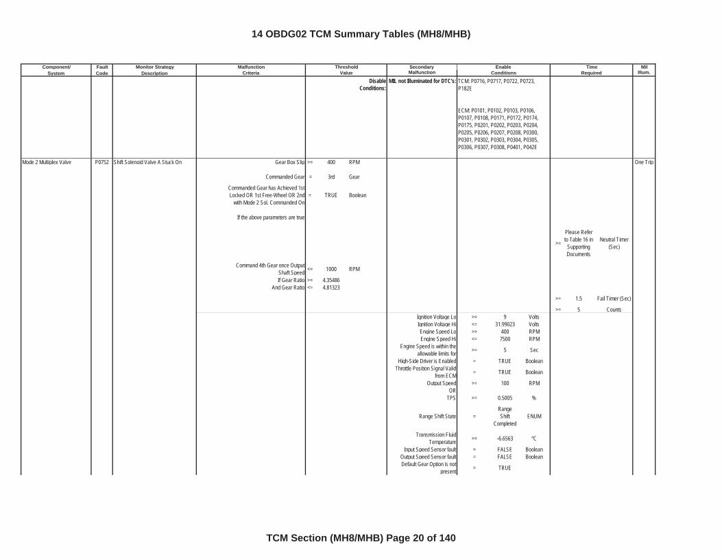
Component/ Fault Monitor Strategy Secondary MilSystem Code Description Malfunction Illum.
Malfunction Threshold Enable TimeCriteria Value Conditions Required
DisableConditions:
MIL not Illuminated for DTC's:
Mode 2 Multiplex Valve P0752 Shift Solenoid Valve A Stuck On Gear Box Slip >= 400 RPM One Trip
Commanded Gear = 3rd Gear
Commanded Gear has Achieved 1st Locked OR 1st Free-Wheel OR 2nd
with Mode 2 Sol. Commanded On= TRUE Boolean
If the above parameters are true
>=
Please Refer to Table 16 in
SupportingDocuments
Neutral Timer (Sec)
Command 4th Gear once Output Shaft Speed <= 1000 RPM
If Gear Ratio >= 4.35486And Gear Ratio <= 4.81323
>= 1.5 Fail Timer (Sec)
>= 5 CountsIgnition Voltage Lo >= 9 VoltsIgnition Voltage Hi <= 31.99023 VoltsEngine Speed Lo >= 400 RPMEngine Speed Hi <= 7500 RPM
Engine Speed is within the allowable limits for >= 5 Sec
High-Side Driver is Enabled = TRUE BooleanThrottle Position Signal Valid
from ECM = TRUE Boolean
Output Speed >= 100 RPMOR
TPS >= 0.5005 %
Range Shift State =RangeShift
CompletedENUM
Transmission Fluid Temperature >= -6.6563 ºC
Input Speed Sensor fault = FALSE BooleanOutput Speed Sensor fault = FALSE BooleanDefault Gear Option is not
present = TRUE
TCM: P0716, P0717, P0722, P0723, P182E
ECM: P0101, P0102, P0103, P0106, P0107, P0108, P0171, P0172, P0174, P0175, P0201, P0202, P0203, P0204, P0205, P0206, P0207, P0208, P0300, P0301, P0302, P0303, P0304, P0305, P0306, P0307, P0308, P0401, P042E
14 OBDG02 TCM Summary Tables (MH8/MHB)
TCM Section (MH8/MHB) Page 20 of 140
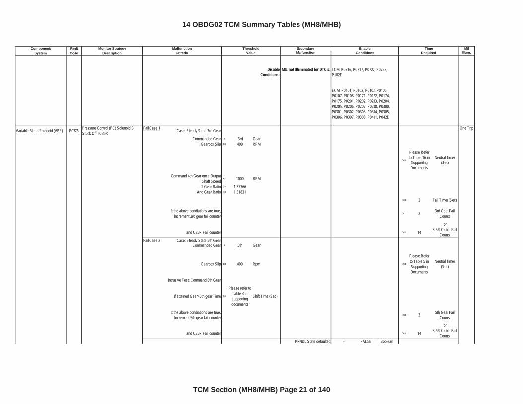
Component/ Fault Monitor Strategy Secondary MilSystem Code Description Malfunction Illum.
Malfunction Threshold Enable TimeCriteria Value Conditions Required
DisableConditions:
MIL not Illuminated for DTC's:
Variable Bleed Solenoid (VBS) P0776 Pressure Control (PC) Solenoid B Stuck Off [C35R]
Fail Case 1 Case: Steady State 3rd Gear One Trip
Commanded Gear = 3rd GearGearbox Slip >= 400 RPM
>=
Please Refer to Table 16 in
SupportingDocuments
Neutral Timer (Sec)
Command 4th Gear once Output Shaft Speed <= 1000 RPM
If Gear Ratio >= 1.37366And Gear Ratio <= 1.51831
>= 3 Fail Timer (Sec)
It the above condiations are true, Increment 3rd gear fail counter >= 2 3rd Gear Fail
Counts
or
and C35R Fail counter >= 14 3-5R Clutch Fail Counts
Fail Case 2 Case: Steady State 5th GearCommanded Gear = 5th Gear
Gearbox Slip >= 400 Rpm >=
Please Refer to Table 5 in SupportingDocuments
Neutral Timer (Sec)
Intrusive Test: Command 6th Gear
If attained Gear=6th gear Time >=
Please refer to Table 3 in supportingdocuments
Shift Time (Sec)
It the above condiations are true, Increment 5th gear fail counter >= 3 5th Gear Fail
Counts
or
and C35R Fail counter >= 14 3-5R Clutch Fail Counts
PRNDL State defaulted = FALSE Boolean
TCM: P0716, P0717, P0722, P0723, P182E
ECM: P0101, P0102, P0103, P0106, P0107, P0108, P0171, P0172, P0174, P0175, P0201, P0202, P0203, P0204, P0205, P0206, P0207, P0208, P0300, P0301, P0302, P0303, P0304, P0305, P0306, P0307, P0308, P0401, P042E
14 OBDG02 TCM Summary Tables (MH8/MHB)
TCM Section (MH8/MHB) Page 21 of 140
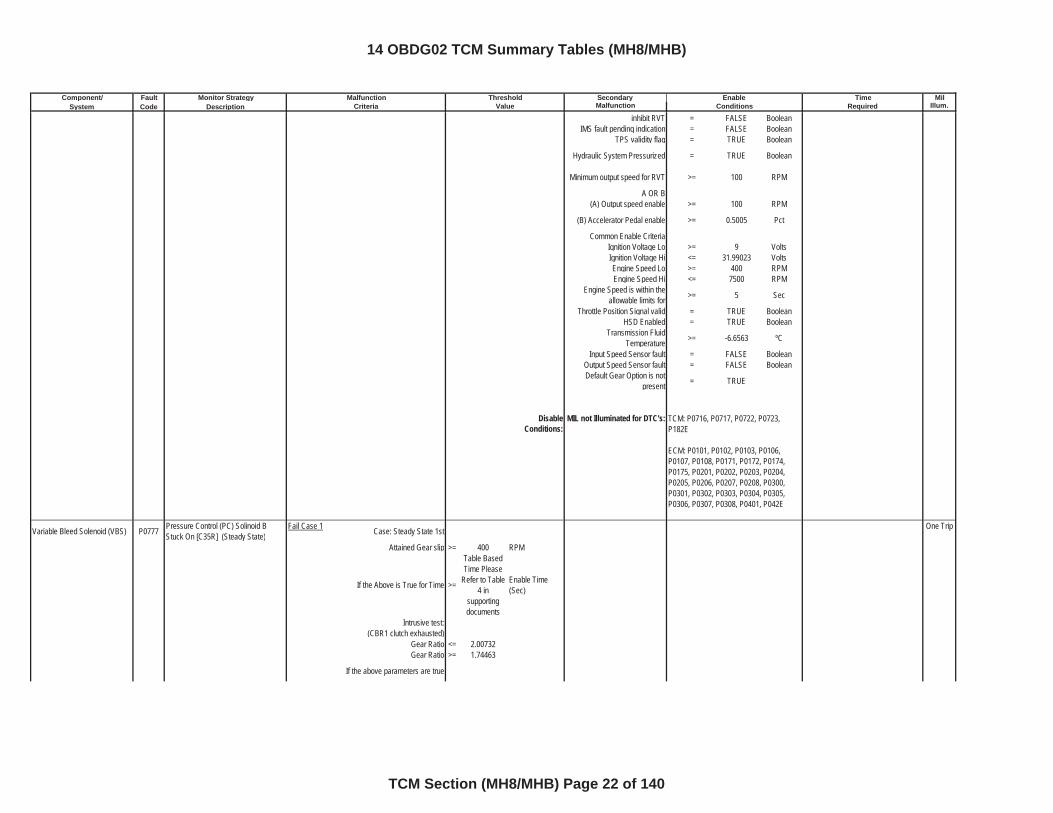
Component/ Fault Monitor Strategy Secondary MilSystem Code Description Malfunction Illum.
Malfunction Threshold Enable TimeCriteria Value Conditions Required
inhibit RVT = FALSE BooleanIMS fault pending indication = FALSE Boolean
TPS validity flag = TRUE Boolean
Hydraulic System Pressurized = TRUE Boolean
Minimum output speed for RVT >= 100 RPM
A OR B(A) Output speed enable >= 100 RPM
(B) Accelerator Pedal enable >= 0.5005 Pct
Common Enable CriteriaIgnition Voltage Lo >= 9 VoltsIgnition Voltage Hi <= 31.99023 VoltsEngine Speed Lo >= 400 RPMEngine Speed Hi <= 7500 RPM
Engine Speed is within the allowable limits for >= 5 Sec
Throttle Position Signal valid = TRUE BooleanHSD Enabled = TRUE Boolean
Transmission Fluid Temperature >= -6.6563 ºC
Input Speed Sensor fault = FALSE BooleanOutput Speed Sensor fault = FALSE BooleanDefault Gear Option is not
present = TRUE
DisableConditions:
MIL not Illuminated for DTC's:
Variable Bleed Solenoid (VBS) P0777 Pressure Control (PC) Solinoid B Stuck On [C35R] (Steady State)
Fail Case 1 Case: Steady State 1st One Trip
Attained Gear slip >= 400 RPM
If the Above is True for Time >=
Table Based Time Please
Refer to Table 4 in
supportingdocuments
Enable Time (Sec)
Intrusive test:(CBR1 clutch exhausted)
Gear Ratio <= 2.00732Gear Ratio >= 1.74463
If the above parameters are true
TCM: P0716, P0717, P0722, P0723, P182E
ECM: P0101, P0102, P0103, P0106, P0107, P0108, P0171, P0172, P0174, P0175, P0201, P0202, P0203, P0204, P0205, P0206, P0207, P0208, P0300, P0301, P0302, P0303, P0304, P0305, P0306, P0307, P0308, P0401, P042E
14 OBDG02 TCM Summary Tables (MH8/MHB)
TCM Section (MH8/MHB) Page 22 of 140
Component/ Fault Monitor Strategy Secondary MilSystem Code Description Malfunction Illum.
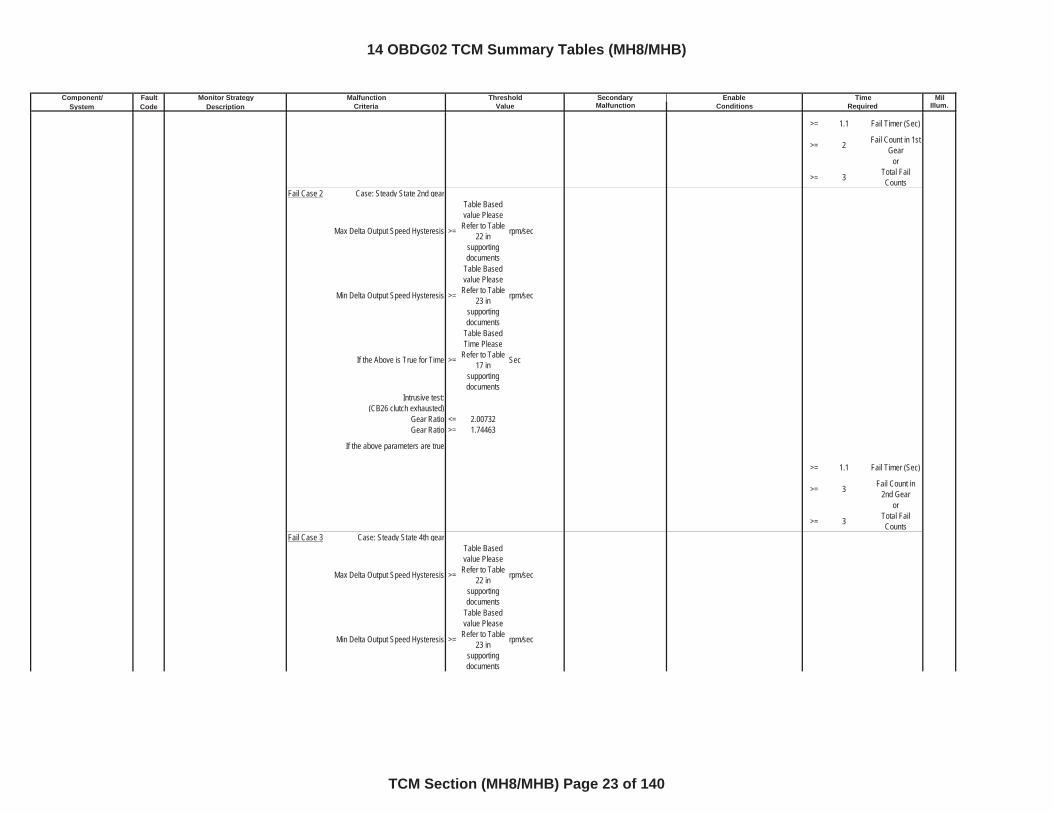
Malfunction Threshold Enable TimeCriteria Value Conditions Required
>= 1.1 Fail Timer (Sec)
>= 2 Fail Count in 1st Gear
or
>= 3 Total Fail Counts
Fail Case 2 Case: Steady State 2nd gear
Max Delta Output Speed Hysteresis >=
Table Based value Please
Refer to Table 22 in
supportingdocuments
rpm/sec
Min Delta Output Speed Hysteresis >=
Table Based value Please
Refer to Table 23 in
supportingdocuments
rpm/sec
If the Above is True for Time >=
Table Based Time Please
Refer to Table 17 in
supportingdocuments
Sec
Intrusive test: (CB26 clutch exhausted)
Gear Ratio <= 2.00732Gear Ratio >= 1.74463
If the above parameters are true
>= 1.1 Fail Timer (Sec)
>= 3 Fail Count in 2nd Gear
or
>= 3 Total Fail Counts
Fail Case 3 Case: Steady State 4th gear
Max Delta Output Speed Hysteresis >=
Table Based value Please
Refer to Table 22 in
supportingdocuments
rpm/sec
Min Delta Output Speed Hysteresis >=
Table Based value Please
Refer to Table 23 in
supportingdocuments
rpm/sec
14 OBDG02 TCM Summary Tables (MH8/MHB)
TCM Section (MH8/MHB) Page 23 of 140
Component/ Fault Monitor Strategy Secondary MilSystem Code Description Malfunction Illum.
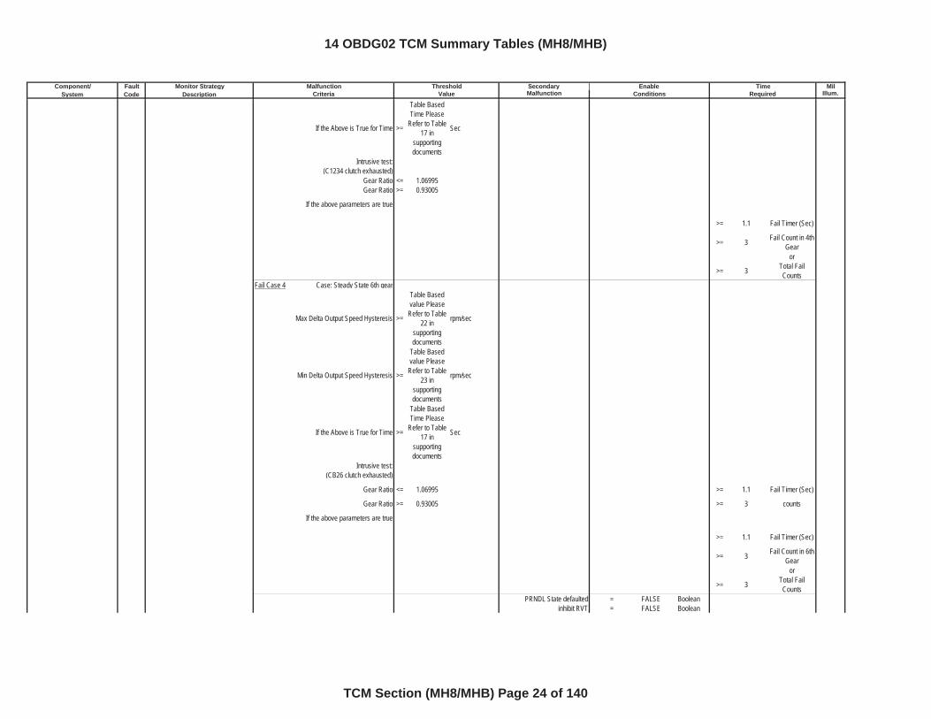
Malfunction Threshold Enable TimeCriteria Value Conditions Required
If the Above is True for Time >=
Table Based Time Please
Refer to Table 17 in
supportingdocuments
Sec
Intrusive test: (C1234 clutch exhausted)
Gear Ratio <= 1.06995Gear Ratio >= 0.93005
If the above parameters are true
>= 1.1 Fail Timer (Sec)
>= 3 Fail Count in 4th Gear
or
>= 3 Total Fail Counts
Fail Case 4 Case: Steady State 6th gear
Max Delta Output Speed Hysteresis >=
Table Based value Please
Refer to Table 22 in
supportingdocuments
rpm/sec
Min Delta Output Speed Hysteresis >=
Table Based value Please
Refer to Table 23 in
supportingdocuments
rpm/sec
If the Above is True for Time >=
Table Based Time Please
Refer to Table 17 in
supportingdocuments
Sec
Intrusive test: (CB26 clutch exhausted)
Gear Ratio <= 1.06995 >= 1.1 Fail Timer (Sec)
Gear Ratio >= 0.93005 >= 3 counts
If the above parameters are true
>= 1.1 Fail Timer (Sec)
>= 3 Fail Count in 6th Gear
or
>= 3 Total Fail Counts
PRNDL State defaulted = FALSE Booleaninhibit RVT = FALSE Boolean
14 OBDG02 TCM Summary Tables (MH8/MHB)
TCM Section (MH8/MHB) Page 24 of 140
Component/ Fault Monitor Strategy Secondary MilSystem Code Description Malfunction Illum.
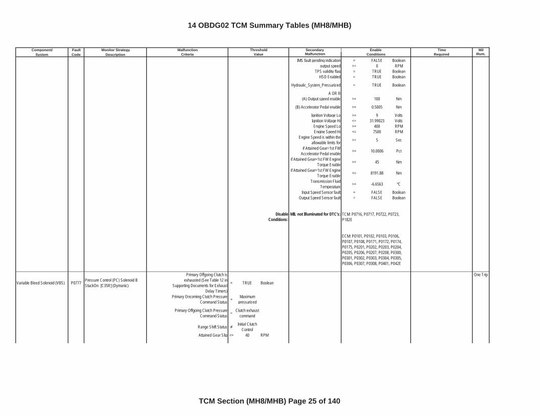
Malfunction Threshold Enable TimeCriteria Value Conditions Required
IMS fault pending indication = FALSE Booleanoutput speed >= 0 RPM
TPS validity flag = TRUE BooleanHSD Enabled = TRUE Boolean
Hydraulic_System_Pressurized = TRUE Boolean
A OR B(A) Output speed enable >= 100 Nm
(B) Accelerator Pedal enable >= 0.5005 Nm
Ignition Voltage Lo >= 9 VoltsIgnition Voltage Hi <= 31.99023 VoltsEngine Speed Lo >= 400 RPMEngine Speed Hi <= 7500 RPM
Engine Speed is within the allowable limits for >= 5 Sec
if Attained Gear=1st FW Accelerator Pedal enable >= 10.0006 Pct
if Attained Gear=1st FW Engine Torque Enable >= 45 Nm
if Attained Gear=1st FW Engine Torque Enable <= 8191.88 Nm
Transmission Fluid Temperature >= -6.6563 ºC
Input Speed Sensor fault = FALSE BooleanOutput Speed Sensor fault = FALSE Boolean
DisableConditions:
MIL not Illuminated for DTC's:
Variable Bleed Solenoid (VBS) P0777 Pressure Control (PC) Solenoid B StuckOn [C35R] (Dymanic)
Primary Offgoing Clutch is exhausted (See Table 12 in
Supporting Documents for Exhaust Delay Timers)
= TRUE Boolean
One Trip
Primary Oncoming Clutch Pressure Command Status = Maximum
pressurized
Primary Offgoing Clutch Pressure Command Status = Clutch exhaust
command
Range Shift Status Initial Clutch Control
Attained Gear Slip <= 40 RPM
TCM: P0716, P0717, P0722, P0723, P182E
ECM: P0101, P0102, P0103, P0106, P0107, P0108, P0171, P0172, P0174, P0175, P0201, P0202, P0203, P0204, P0205, P0206, P0207, P0208, P0300, P0301, P0302, P0303, P0304, P0305, P0306, P0307, P0308, P0401, P042E
14 OBDG02 TCM Summary Tables (MH8/MHB)
TCM Section (MH8/MHB) Page 25 of 140
Component/ Fault Monitor Strategy Secondary MilSystem Code Description Malfunction Illum.
Malfunction Threshold Enable TimeCriteria Value Conditions Required
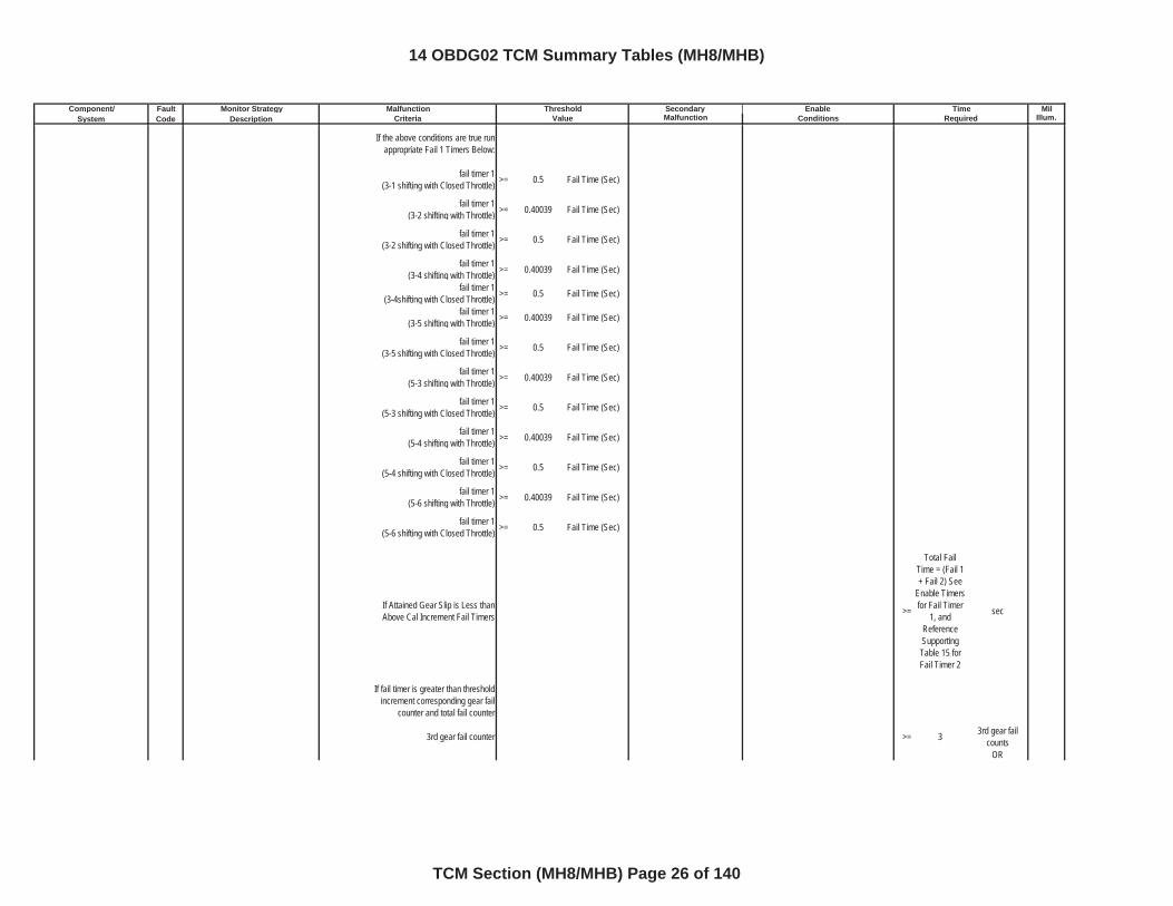
If the above conditions are true run appropriate Fail 1 Timers Below:
fail timer 1(3-1 shifting with Closed Throttle) >= 0.5 Fail Time (Sec)
fail timer 1(3-2 shifting with Throttle) >= 0.40039 Fail Time (Sec)
fail timer 1(3-2 shifting with Closed Throttle) >= 0.5 Fail Time (Sec)
fail timer 1(3-4 shifting with Throttle) >= 0.40039 Fail Time (Sec)
fail timer 1(3-4shifting with Closed Throttle) >= 0.5 Fail Time (Sec)
fail timer 1(3-5 shifting with Throttle) >= 0.40039 Fail Time (Sec)
fail timer 1(3-5 shifting with Closed Throttle) >= 0.5 Fail Time (Sec)
fail timer 1(5-3 shifting with Throttle) >= 0.40039 Fail Time (Sec)
fail timer 1(5-3 shifting with Closed Throttle) >= 0.5 Fail Time (Sec)
fail timer 1(5-4 shifting with Throttle) >= 0.40039 Fail Time (Sec)
fail timer 1(5-4 shifting with Closed Throttle) >= 0.5 Fail Time (Sec)
fail timer 1(5-6 shifting with Throttle) >= 0.40039 Fail Time (Sec)
fail timer 1(5-6 shifting with Closed Throttle) >= 0.5 Fail Time (Sec)
If Attained Gear Slip is Less than Above Cal Increment Fail Timers >=
Total Fail Time = (Fail 1 + Fail 2) See
Enable Timers for Fail Timer
1, and ReferenceSupportingTable 15 for Fail Timer 2
sec
If fail timer is greater than threshold increment corresponding gear fail
counter and total fail counter
3rd gear fail counter >= 3 3rd gear fail counts
OR
14 OBDG02 TCM Summary Tables (MH8/MHB)
TCM Section (MH8/MHB) Page 26 of 140
Component/ Fault Monitor Strategy Secondary MilSystem Code Description Malfunction Illum.
Malfunction Threshold Enable TimeCriteria Value Conditions Required
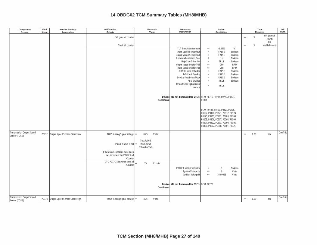
5th gear fail counter >= 3 5th gear fail counts
ORTotal fail counter >= 3 total fail counts
TUT Enable temperature >= -6.6563 ºCInput Speed Sensor fault = FALSE Boolean
Output Speed Sensor fault = FALSE BooleanCommand / Attained Gear 1st Boolean
High Side Driver ON = TRUE Booleanoutput speed limit for TUT >= 200 RPM
input speed limit for TUT >= 200 RPMPRNDL state defaulted = FALSE Boolean
IMS Fault Pending = FALSE BooleanService Fast Learn Mode = FALSE Boolean
HSD Enabled = TRUE BooleanDefault Gear Option is not
present = TRUE
DisableConditions:
MIL not Illuminated for DTC's:
Transmission Output Speed Sensor (TOSS) P077C Output Speed Sensor Circuit Low TOSS Analog Signal Voltage <= 0.25 Volts >= 0.05 sec One Trip
P077C Status is not =Test Failed This Key On
or Fault Active
If the above conditons have been met, increment the P077C Fail
CounterDTC P077C Sets when the Fail
Counter >= 75 Counts
P077C Enable Calibration = 1 BooleanIgnition Voltage Lo >= 9 VoltsIgnition Voltage Hi <= 31.99023 Volts
DisableConditions:
MIL not Illuminated for DTC's:
Transmission Output Speed Sensor (TOSS) P077D Output Speed Sensor Circuit High TOSS Analog Signal Voltage >= 4.75 Volts >= 0.05 sec One Trip
TCM: P0716, P0717, P0722, P0723, P182E
ECM: P0101, P0102, P0103, P0106, P0107, P0108, P0171, P0172, P0174, P0175, P0201, P0202, P0203, P0204, P0205, P0206, P0207, P0208, P0300, P0301, P0302, P0303, P0304, P0305, P0306, P0307, P0308, P0401, P042E
TCM: P077D
14 OBDG02 TCM Summary Tables (MH8/MHB)
TCM Section (MH8/MHB) Page 27 of 140
Component/ Fault Monitor Strategy Secondary MilSystem Code Description Malfunction Illum.
Malfunction Threshold Enable TimeCriteria Value Conditions Required
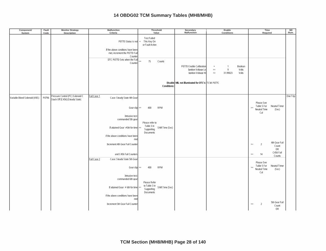
P077D Status is not =Test Failed This Key On
or Fault Active
If the above conditons have been met, increment the P077D Fail
CounterDTC P077D Sets when the Fail
Counter >= 75 Counts
P077D Enable Calibration = 1 BooleanIgnition Voltage Lo >= 9 VoltsIgnition Voltage Hi <= 31.99023 Volts
DisableConditions:
MIL not Illuminated for DTC's:
Variable Bleed Solenoid (VBS) P0796 Pressure Control (PC) Solenoid C Stuck Off [C456] (Steady State)
Fail Case 1 Case: Steady State 4th Gear One Trip
Gear slip >= 400 RPM >=
Please See Table 5 For
Neutral Time Cal
Neutral Timer (Sec)
Intrusive test:commanded 5th gear
If attained Gear 5th for time >=
Please refer to Table 3 in SupportingDocuments
Shift Time (Sec)
if the above conditions have been met
Increment 4th Gear Fail Counter >= 2 4th Gear Fail Count
OR
and C456 Fail Counters >= 14 C456 Fail Counts
Fail Case 2 Case: Steady State 5th Gear
Gear slip >= 400 RPM >=
Please See Table 5 For
Neutral Time Cal
Neutral Timer (Sec)
Intrusive test:commanded 6th gear
If attained Gear 6th for time >=
Please Refer to Table 3 in SupportingDocuments
Shift Time (Sec)
if the above conditions have been met
Increment 5th Gear Fail Counter >= 2 5th Gear Fail Count
OR
TCM: P077C
14 OBDG02 TCM Summary Tables (MH8/MHB)
TCM Section (MH8/MHB) Page 28 of 140
Component/ Fault Monitor Strategy Secondary MilSystem Code Description Malfunction Illum.
Malfunction Threshold Enable TimeCriteria Value Conditions Required
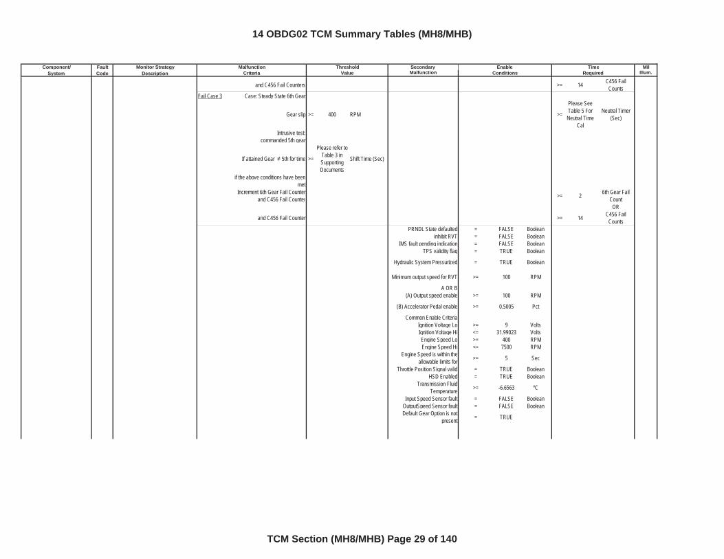
and C456 Fail Counters >= 14 C456 Fail Counts
Fail Case 3 Case: Steady State 6th Gear
Gear slip >= 400 RPM >=
Please See Table 5 For
Neutral Time Cal
Neutral Timer (Sec)
Intrusive test:commanded 5th gear
If attained Gear 5th for time >=
Please refer to Table 3 in SupportingDocuments
Shift Time (Sec)
if the above conditions have been met
Increment 6th Gear Fail Counter and C456 Fail Counter >= 2 6th Gear Fail
CountOR
and C456 Fail Counter >= 14 C456 Fail Counts
PRNDL State defaulted = FALSE Booleaninhibit RVT = FALSE Boolean
IMS fault pending indication = FALSE BooleanTPS validity flag = TRUE Boolean
Hydraulic System Pressurized = TRUE Boolean
Minimum output speed for RVT >= 100 RPM
A OR B(A) Output speed enable >= 100 RPM
(B) Accelerator Pedal enable >= 0.5005 Pct
Common Enable CriteriaIgnition Voltage Lo >= 9 VoltsIgnition Voltage Hi <= 31.99023 VoltsEngine Speed Lo >= 400 RPMEngine Speed Hi <= 7500 RPM
Engine Speed is within the allowable limits for >= 5 Sec
Throttle Position Signal valid = TRUE BooleanHSD Enabled = TRUE Boolean
Transmission Fluid Temperature >= -6.6563 ºC
Input Speed Sensor fault = FALSE BooleanOutputSpeed Sensor fault = FALSE BooleanDefault Gear Option is not
present = TRUE
14 OBDG02 TCM Summary Tables (MH8/MHB)
TCM Section (MH8/MHB) Page 29 of 140
Component/ Fault Monitor Strategy Secondary MilSystem Code Description Malfunction Illum.
Malfunction Threshold Enable TimeCriteria Value Conditions Required
DisableConditions:
MIL not Illuminated for DTC's:
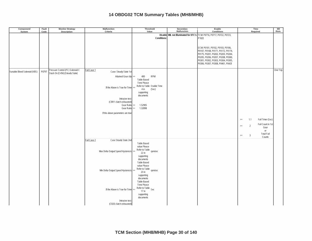
Variable Bleed Solenoid (VBS) P0797 Pressure Control (PC) Solenoid C Stuck On [C456] (Steady State)
Fail Case 1 Case: Steady State 1st One Trip
Attained Gear slip >= 400 RPM
If the Above is True for Time >=
Table Based Time Please
Refer to Table 4 in
supportingdocuments
Enable Time (Sec)
Intrusive test:(CBR1 clutch exhausted)
Gear Ratio <= 1.52905Gear Ratio >= 1.32898
If the above parameters are true
>= 1.1 Fail Timer (Sec)
>= 2 Fail Count in 1st Gear
or
>= 3 Total Fail Counts
Fail Case 2 Case Steady State 2nd
Max Delta Output Speed Hysteresis >=
Table Based value Please
Refer to Table 22 in
supportingdocuments
rpm/sec
Min Delta Output Speed Hysteresis >=
Table Based value Please
Refer to Table 23 in
supportingdocuments
rpm/sec
If the Above is True for Time >=
Table Based Time Please
Refer to Table 17 in
supportingdocuments
Sec
Intrusive test: (CB26 clutch exhausted)
TCM: P0716, P0717, P0722, P0723, P182E
ECM: P0101, P0102, P0103, P0106, P0107, P0108, P0171, P0172, P0174, P0175, P0201, P0202, P0203, P0204, P0205, P0206, P0207, P0208, P0300, P0301, P0302, P0303, P0304, P0305, P0306, P0307, P0308, P0401, P042E
14 OBDG02 TCM Summary Tables (MH8/MHB)
TCM Section (MH8/MHB) Page 30 of 140
Component/ Fault Monitor Strategy Secondary MilSystem Code Description Malfunction Illum.
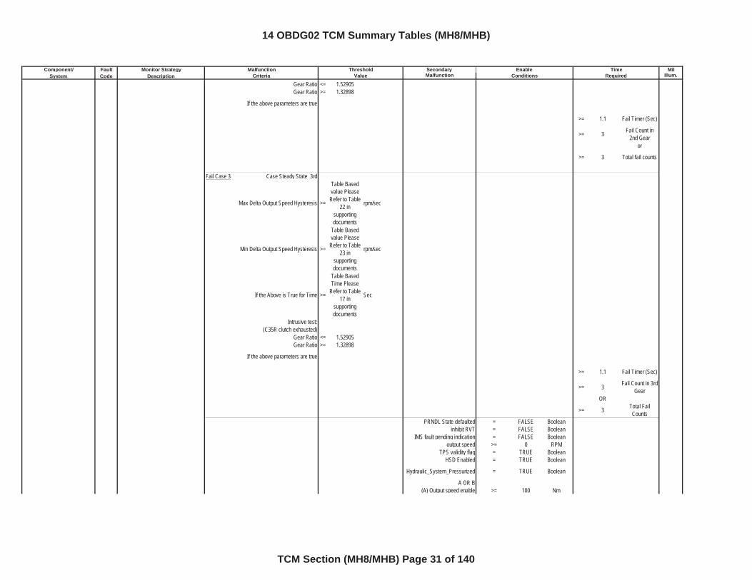
Malfunction Threshold Enable TimeCriteria Value Conditions Required
Gear Ratio <= 1.52905Gear Ratio >= 1.32898
If the above parameters are true
>= 1.1 Fail Timer (Sec)
>= 3 Fail Count in 2nd Gear
or
>= 3 Total fail counts
Fail Case 3 Case Steady State 3rd
Max Delta Output Speed Hysteresis >=
Table Based value Please
Refer to Table 22 in
supportingdocuments
rpm/sec
Min Delta Output Speed Hysteresis >=
Table Based value Please
Refer to Table 23 in
supportingdocuments
rpm/sec
If the Above is True for Time >=
Table Based Time Please
Refer to Table 17 in
supportingdocuments
Sec
Intrusive test: (C35R clutch exhausted)
Gear Ratio <= 1.52905Gear Ratio >= 1.32898
If the above parameters are true
>= 1.1 Fail Timer (Sec)
>= 3 Fail Count in 3rd Gear
OR
>= 3 Total Fail Counts
PRNDL State defaulted = FALSE Booleaninhibit RVT = FALSE Boolean
IMS fault pending indication = FALSE Booleanoutput speed >= 0 RPM
TPS validity flag = TRUE BooleanHSD Enabled = TRUE Boolean
Hydraulic_System_Pressurized = TRUE Boolean
A OR B(A) Output speed enable >= 100 Nm
14 OBDG02 TCM Summary Tables (MH8/MHB)
TCM Section (MH8/MHB) Page 31 of 140
Component/ Fault Monitor Strategy Secondary MilSystem Code Description Malfunction Illum.
Malfunction Threshold Enable TimeCriteria Value Conditions Required
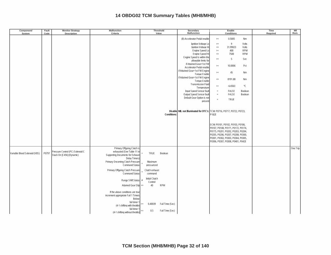
(B) Accelerator Pedal enable >= 0.5005 Nm
Ignition Voltage Lo >= 9 VoltsIgnition Voltage Hi <= 31.99023 VoltsEngine Speed Lo >= 400 RPMEngine Speed Hi <= 7500 RPM
Engine Speed is within the allowable limits for >= 5 Sec
if Attained Gear=1st FW Accelerator Pedal enable >= 10.0006 Pct
if Attained Gear=1st FW Engine Torque Enable >= 45 Nm
if Attained Gear=1st FW Engine Torque Enable <= 8191.88 Nm
Transmission Fluid Temperature >= -6.6563 ºC
Input Speed Sensor fault = FALSE BooleanOutput Speed Sensor fault = FALSE BooleanDefault Gear Option is not
present = TRUE
DisableConditions:
MIL not Illuminated for DTC's:
Variable Bleed Solenoid (VBS) P0797 Pressure Control (PC) Solenoid C Stuck On [C456] (Dynamic)
Primary Offgoing Clutch is exhausted (See Table 11 in
Supporting Documents for Exhaust Delay Timers)
= TRUE Boolean
One Trip
Primary Oncoming Clutch Pressure Command Status = Maximum
pressurized
Primary Offgoing Clutch Pressure Command Status = Clutch exhaust
command
Range Shift Status Initial Clutch Control
Attained Gear Slip <= 40 RPM
If the above conditions are true increment appropriate Fail 1 Timers
Below:fail timer 1
(4-1 shifting with throttle) >= 0.40039 Fail Time (Sec)
fail timer 1(4-1 shifting without throttle) >= 0.5 Fail Time (Sec)
TCM: P0716, P0717, P0722, P0723, P182E
ECM: P0101, P0102, P0103, P0106, P0107, P0108, P0171, P0172, P0174, P0175, P0201, P0202, P0203, P0204, P0205, P0206, P0207, P0208, P0300, P0301, P0302, P0303, P0304, P0305, P0306, P0307, P0308, P0401, P042E
14 OBDG02 TCM Summary Tables (MH8/MHB)
TCM Section (MH8/MHB) Page 32 of 140
Component/ Fault Monitor Strategy Secondary MilSystem Code Description Malfunction Illum.
Malfunction Threshold Enable TimeCriteria Value Conditions Required
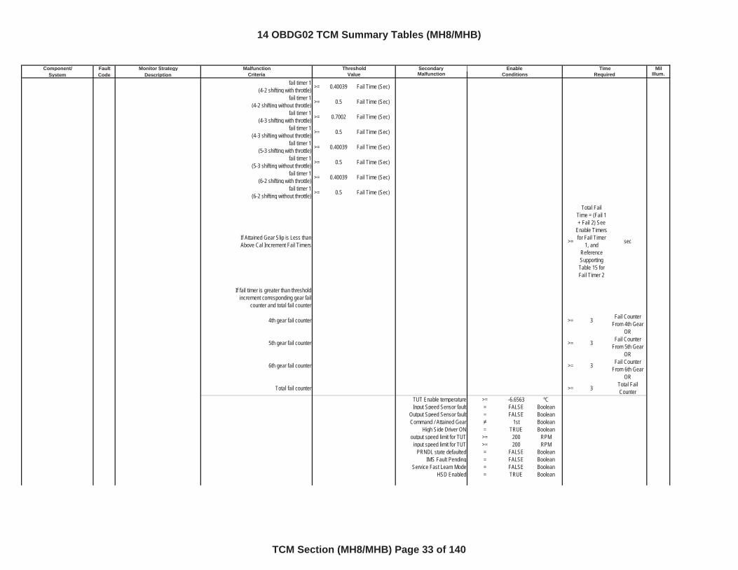
fail timer 1(4-2 shifting with throttle) >= 0.40039 Fail Time (Sec)
fail timer 1(4-2 shifting without throttle) >= 0.5 Fail Time (Sec)
fail timer 1(4-3 shifting with throttle) >= 0.7002 Fail Time (Sec)
fail timer 1(4-3 shifting without throttle) >= 0.5 Fail Time (Sec)
fail timer 1(5-3 shifting with throttle) >= 0.40039 Fail Time (Sec)
fail timer 1(5-3 shifting without throttle) >= 0.5 Fail Time (Sec)
fail timer 1(6-2 shifting with throttle) >= 0.40039 Fail Time (Sec)
fail timer 1(6-2 shifting without throttle) >= 0.5 Fail Time (Sec)
If Attained Gear Slip is Less than Above Cal Increment Fail Timers >=
Total Fail Time = (Fail 1 + Fail 2) See
Enable Timers for Fail Timer
1, and ReferenceSupportingTable 15 for Fail Timer 2
sec
If fail timer is greater than threshold increment corresponding gear fail
counter and total fail counter
4th gear fail counter >= 3 Fail Counter From 4th Gear
OR
5th gear fail counter >= 3 Fail Counter From 5th Gear
OR
6th gear fail counter >= 3 Fail Counter From 6th Gear
OR
Total fail counter >= 3 Total Fail Counter
TUT Enable temperature >= -6.6563 ºCInput Speed Sensor fault = FALSE Boolean
Output Speed Sensor fault = FALSE BooleanCommand / Attained Gear 1st Boolean
High Side Driver ON = TRUE Booleanoutput speed limit for TUT >= 200 RPM
input speed limit for TUT >= 200 RPMPRNDL state defaulted = FALSE Boolean
IMS Fault Pending = FALSE BooleanService Fast Learn Mode = FALSE Boolean
HSD Enabled = TRUE Boolean
14 OBDG02 TCM Summary Tables (MH8/MHB)
TCM Section (MH8/MHB) Page 33 of 140
Component/ Fault Monitor Strategy Secondary MilSystem Code Description Malfunction Illum.
Malfunction Threshold Enable TimeCriteria Value Conditions Required
DisableConditions:
MIL not Illuminated for DTC's:
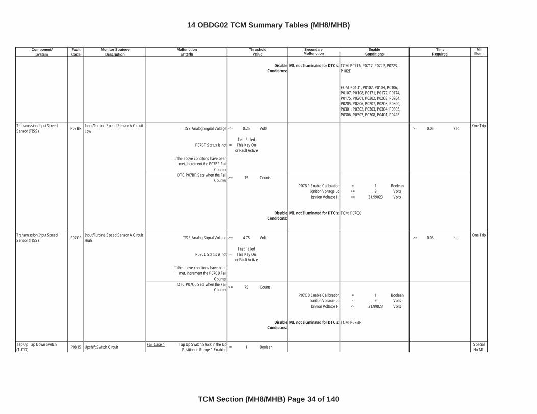
Transmission Input Speed Sensor (TISS) P07BF Input/Turbine Speed Sensor A Circuit
Low TISS Analog Signal Voltage <= 0.25 Volts >= 0.05 sec One Trip
P07BF Status is not =Test Failed This Key On
or Fault Active
If the above conditons have been met, increment the P07BF Fail
CounterDTC P07BF Sets when the Fail
Counter >= 75 Counts
P07BF Enable Calibration = 1 BooleanIgnition Voltage Lo >= 9 VoltsIgnition Voltage Hi <= 31.99023 Volts
DisableConditions:
MIL not Illuminated for DTC's:
Transmission Input Speed Sensor (TISS) P07C0 Input/Turbine Speed Sensor A Circuit
High TISS Analog Signal Voltage >= 4.75 Volts >= 0.05 sec One Trip
P07C0 Status is not =Test Failed This Key On
or Fault Active
If the above conditons have been met, increment the P07C0 Fail
CounterDTC P07C0 Sets when the Fail
Counter >= 75 Counts
P07C0 Enable Calibration = 1 BooleanIgnition Voltage Lo >= 9 VoltsIgnition Voltage Hi <= 31.99023 Volts
DisableConditions:
MIL not Illuminated for DTC's:
Tap Up Tap Down Switch (TUTD) P0815 Upshift Switch Circuit Fail Case 1 Tap Up Switch Stuck in the Up
Position in Range 1 Enabled = 1 Boolean Special No MIL
TCM: P0716, P0717, P0722, P0723, P182E
ECM: P0101, P0102, P0103, P0106, P0107, P0108, P0171, P0172, P0174, P0175, P0201, P0202, P0203, P0204, P0205, P0206, P0207, P0208, P0300, P0301, P0302, P0303, P0304, P0305, P0306, P0307, P0308, P0401, P042E
TCM: P07C0
TCM: P07BF
14 OBDG02 TCM Summary Tables (MH8/MHB)
TCM Section (MH8/MHB) Page 34 of 140
Component/ Fault Monitor Strategy Secondary MilSystem Code Description Malfunction Illum.
Malfunction Threshold Enable TimeCriteria Value Conditions Required
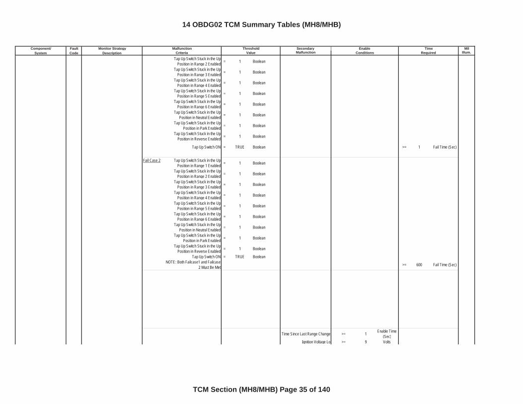
Tap Up Switch Stuck in the Up Position in Range 2 Enabled = 1 Boolean
Tap Up Switch Stuck in the Up Position in Range 3 Enabled = 1 Boolean
Tap Up Switch Stuck in the Up Position in Range 4 Enabled = 1 Boolean
Tap Up Switch Stuck in the Up Position in Range 5 Enabled = 1 Boolean
Tap Up Switch Stuck in the Up Position in Range 6 Enabled = 1 Boolean
Tap Up Switch Stuck in the Up Position in Neutral Enabled = 1 Boolean
Tap Up Switch Stuck in the Up Position in Park Enabled = 1 Boolean
Tap Up Switch Stuck in the Up Position in Reverse Enabled = 1 Boolean
Tap Up Switch ON = TRUE Boolean >= 1 Fail Time (Sec)
Fail Case 2 Tap Up Switch Stuck in the Up Position in Range 1 Enabled = 1 Boolean
Tap Up Switch Stuck in the Up Position in Range 2 Enabled = 1 Boolean
Tap Up Switch Stuck in the Up Position in Range 3 Enabled = 1 Boolean
Tap Up Switch Stuck in the Up Position in Range 4 Enabled = 1 Boolean
Tap Up Switch Stuck in the Up Position in Range 5 Enabled = 1 Boolean
Tap Up Switch Stuck in the Up Position in Range 6 Enabled = 1 Boolean
Tap Up Switch Stuck in the Up Position in Neutral Enabled = 1 Boolean
Tap Up Switch Stuck in the Up Position in Park Enabled = 1 Boolean
Tap Up Switch Stuck in the Up Position in Reverse Enabled = 1 Boolean
Tap Up Switch ON = TRUE BooleanNOTE: Both Failcase1 and Failcase
2 Must Be Met >= 600 Fail Time (Sec)
Time Since Last Range Change >= 1 Enable Time (Sec)
Ignition Voltage Lo >= 9 Volts
14 OBDG02 TCM Summary Tables (MH8/MHB)
TCM Section (MH8/MHB) Page 35 of 140
Component/ Fault Monitor Strategy Secondary MilSystem Code Description Malfunction Illum.
Malfunction Threshold Enable TimeCriteria Value Conditions Required
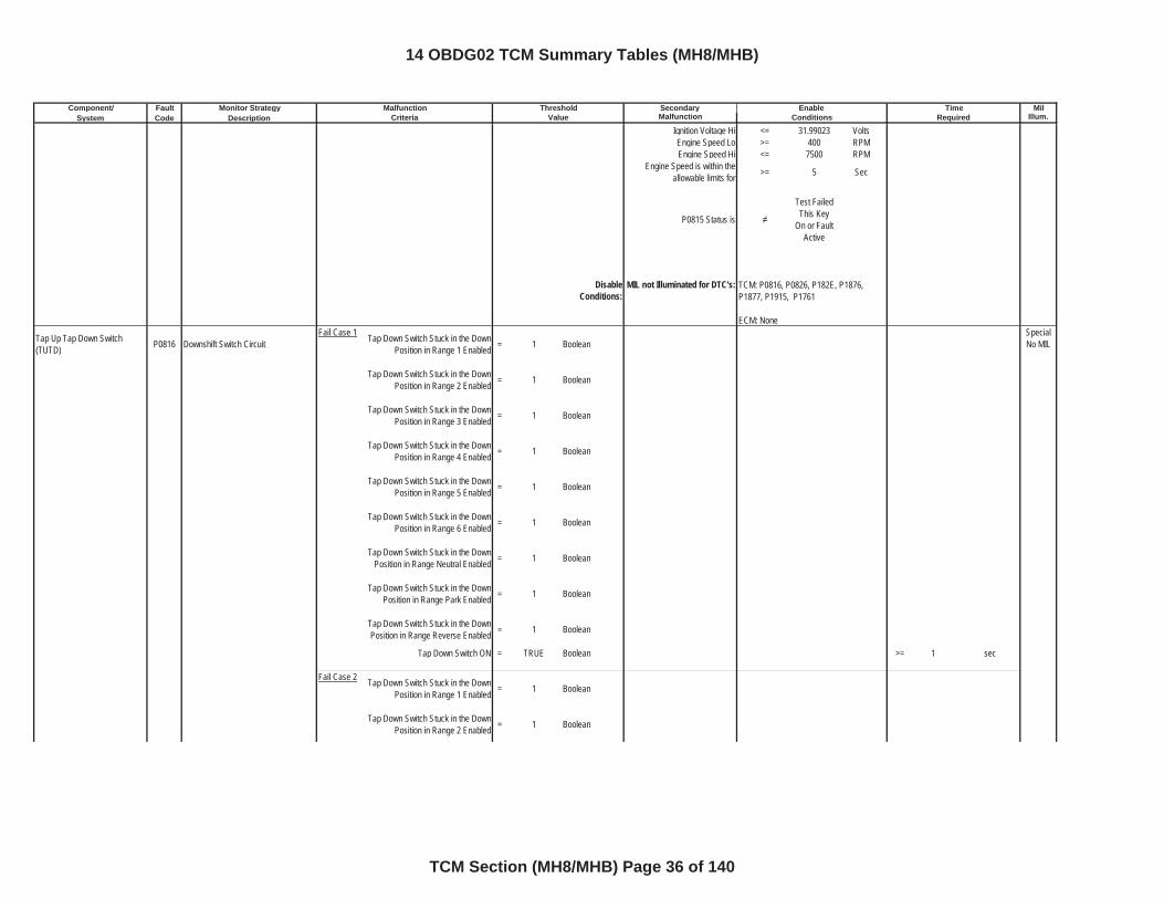
Ignition Voltage Hi <= 31.99023 VoltsEngine Speed Lo >= 400 RPMEngine Speed Hi <= 7500 RPM
Engine Speed is within the allowable limits for >= 5 Sec
P0815 Status is
Test Failed This Key
On or Fault Active
DisableConditions:
MIL not Illuminated for DTC's:
Tap Up Tap Down Switch (TUTD) P0816 Downshift Switch Circuit
Fail Case 1 Tap Down Switch Stuck in the Down Position in Range 1 Enabled = 1 Boolean
Special No MIL
Tap Down Switch Stuck in the Down Position in Range 2 Enabled = 1 Boolean
Tap Down Switch Stuck in the Down Position in Range 3 Enabled = 1 Boolean
Tap Down Switch Stuck in the Down Position in Range 4 Enabled = 1 Boolean
Tap Down Switch Stuck in the Down Position in Range 5 Enabled = 1 Boolean
Tap Down Switch Stuck in the Down Position in Range 6 Enabled = 1 Boolean
Tap Down Switch Stuck in the Down Position in Range Neutral Enabled = 1 Boolean
Tap Down Switch Stuck in the Down Position in Range Park Enabled = 1 Boolean
Tap Down Switch Stuck in the Down Position in Range Reverse Enabled = 1 Boolean
Tap Down Switch ON = TRUE Boolean >= 1 sec
Fail Case 2 Tap Down Switch Stuck in the Down Position in Range 1 Enabled = 1 Boolean
Tap Down Switch Stuck in the Down Position in Range 2 Enabled = 1 Boolean
TCM: P0816, P0826, P182E, P1876, P1877, P1915, P1761
ECM: None
14 OBDG02 TCM Summary Tables (MH8/MHB)
TCM Section (MH8/MHB) Page 36 of 140
Component/ Fault Monitor Strategy Secondary MilSystem Code Description Malfunction Illum.
Malfunction Threshold Enable TimeCriteria Value Conditions Required
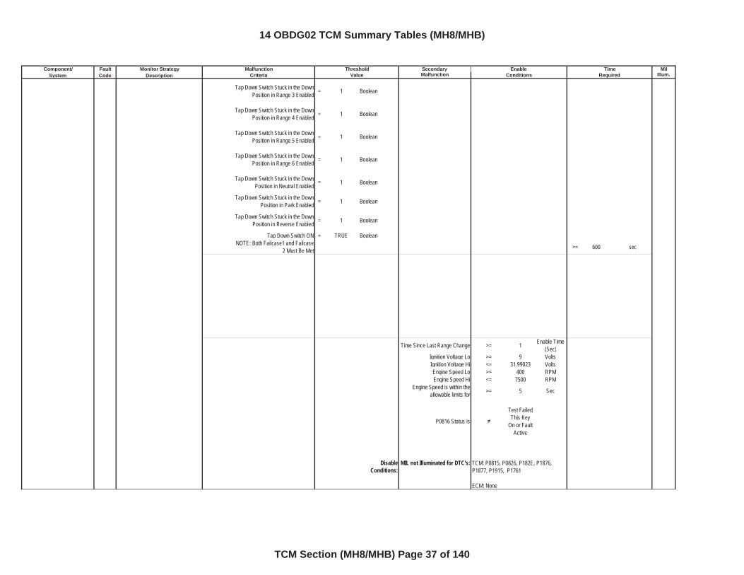
Tap Down Switch Stuck in the Down Position in Range 3 Enabled = 1 Boolean
Tap Down Switch Stuck in the Down Position in Range 4 Enabled = 1 Boolean
Tap Down Switch Stuck in the Down Position in Range 5 Enabled = 1 Boolean
Tap Down Switch Stuck in the Down Position in Range 6 Enabled = 1 Boolean
Tap Down Switch Stuck in the Down Position in Neutral Enabled = 1 Boolean
Tap Down Switch Stuck in the Down Position in Park Enabled = 1 Boolean
Tap Down Switch Stuck in the Down Position in Reverse Enabled = 1 Boolean
Tap Down Switch ON = TRUE BooleanNOTE: Both Failcase1 and Failcase
2 Must Be Met >= 600 sec
Time Since Last Range Change >= 1 Enable Time (Sec)
Ignition Voltage Lo >= 9 VoltsIgnition Voltage Hi <= 31.99023 VoltsEngine Speed Lo >= 400 RPMEngine Speed Hi <= 7500 RPM
Engine Speed is within the allowable limits for >= 5 Sec
P0816 Status is
Test Failed This Key
On or Fault Active
DisableConditions:
MIL not Illuminated for DTC's: TCM: P0815, P0826, P182E, P1876, P1877, P1915, P1761
ECM: None
14 OBDG02 TCM Summary Tables (MH8/MHB)
TCM Section (MH8/MHB) Page 37 of 140
Component/ Fault Monitor Strategy Secondary MilSystem Code Description Malfunction Illum.
Malfunction Threshold Enable TimeCriteria Value Conditions Required
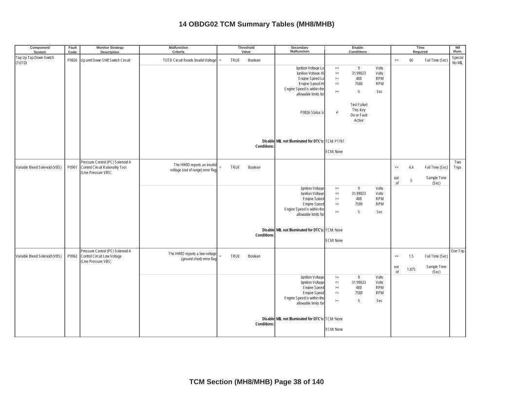
Tap Up Tap Down Switch (TUTD) P0826 Up and Down Shift Switch Circuit TUTD Circuit Reads Invalid Voltage = TRUE Boolean >= 60 Fail Time (Sec) Special
No MILIgnition Voltage Lo >= 9 VoltsIgnition Voltage Hi <= 31.99023 VoltsEngine Speed Lo >= 400 RPMEngine Speed Hi <= 7500 RPM
Engine Speed is within the allowable limits for >= 5 Sec
P0826 Status is
Test Failed This Key
On or Fault Active
DisableConditions:
MIL not Illuminated for DTC's:
Variable Bleed Solenoid (VBS) P0961Pressure Control (PC) Solenoid A Control Circuit Rationality Test(Line Pressure VBS)
The HWIO reports an invalid voltage (out of range) error flag = TRUE Boolean >= 4.4 Fail Time (Sec)
TwoTrips
outof 5 Sample Time
(Sec)Ignition Voltage >= 9 VoltsIgnition Voltage <= 31.99023 Volts
Engine Speed >= 400 RPMEngine Speed <= 7500 RPM
Engine Speed is within the allowable limits for >= 5 Sec
DisableConditions:
MIL not Illuminated for DTC's:
Variable Bleed Solenoid (VBS) P0962Pressure Control (PC) Solenoid A Control Circuit Low Voltage(Line Pressure VBS)
The HWIO reports a low voltage (ground short) error flag = TRUE Boolean >= 1.5 Fail Time (Sec)
One Trip
outof 1.875 Sample Time
(Sec)Ignition Voltage >= 9 VoltsIgnition Voltage <= 31.99023 Volts
Engine Speed >= 400 RPMEngine Speed <= 7500 RPM
Engine Speed is within the allowable limits for >= 5 Sec
DisableConditions:
MIL not Illuminated for DTC's:
TCM: P1761
ECM: None
TCM: None
ECM: None
TCM: None
ECM: None
14 OBDG02 TCM Summary Tables (MH8/MHB)
TCM Section (MH8/MHB) Page 38 of 140
Component/ Fault Monitor Strategy Secondary MilSystem Code Description Malfunction Illum.
Malfunction Threshold Enable TimeCriteria Value Conditions Required
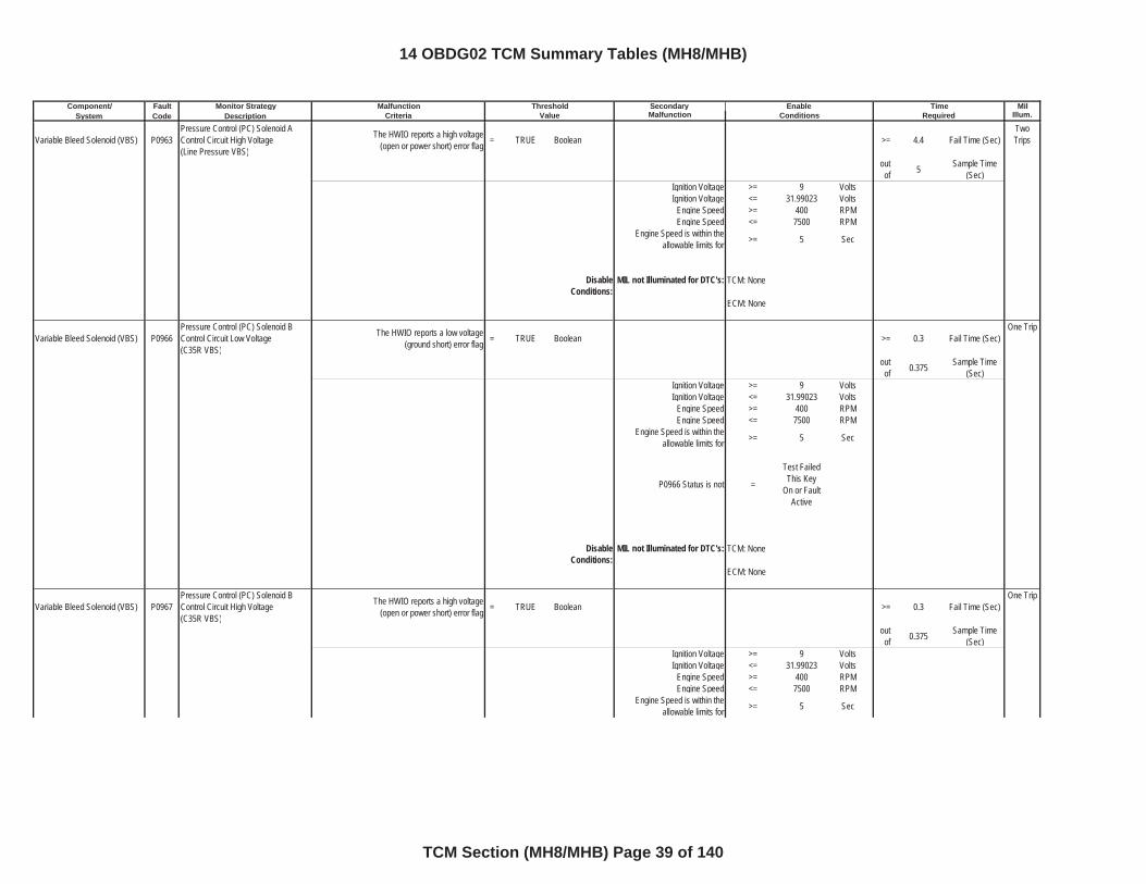
Variable Bleed Solenoid (VBS) P0963Pressure Control (PC) Solenoid A Control Circuit High Voltage(Line Pressure VBS)
The HWIO reports a high voltage (open or power short) error flag = TRUE Boolean >= 4.4 Fail Time (Sec)
TwoTrips
outof 5 Sample Time
(Sec)Ignition Voltage >= 9 VoltsIgnition Voltage <= 31.99023 Volts
Engine Speed >= 400 RPMEngine Speed <= 7500 RPM
Engine Speed is within the allowable limits for >= 5 Sec
DisableConditions:
MIL not Illuminated for DTC's:
Variable Bleed Solenoid (VBS) P0966Pressure Control (PC) Solenoid B Control Circuit Low Voltage(C35R VBS)
The HWIO reports a low voltage (ground short) error flag = TRUE Boolean >= 0.3 Fail Time (Sec)
One Trip
outof 0.375 Sample Time
(Sec)Ignition Voltage >= 9 VoltsIgnition Voltage <= 31.99023 Volts
Engine Speed >= 400 RPMEngine Speed <= 7500 RPM
Engine Speed is within the allowable limits for >= 5 Sec
P0966 Status is not =
Test Failed This Key
On or Fault Active
DisableConditions:
MIL not Illuminated for DTC's:
Variable Bleed Solenoid (VBS) P0967Pressure Control (PC) Solenoid B Control Circuit High Voltage(C35R VBS)
The HWIO reports a high voltage (open or power short) error flag = TRUE Boolean >= 0.3 Fail Time (Sec)
One Trip
outof 0.375 Sample Time
(Sec)Ignition Voltage >= 9 VoltsIgnition Voltage <= 31.99023 Volts
Engine Speed >= 400 RPMEngine Speed <= 7500 RPM
Engine Speed is within the allowable limits for >= 5 Sec
TCM: None
ECM: None
TCM: None
ECM: None
14 OBDG02 TCM Summary Tables (MH8/MHB)
TCM Section (MH8/MHB) Page 39 of 140
Component/ Fault Monitor Strategy Secondary MilSystem Code Description Malfunction Illum.
Malfunction Threshold Enable TimeCriteria Value Conditions Required
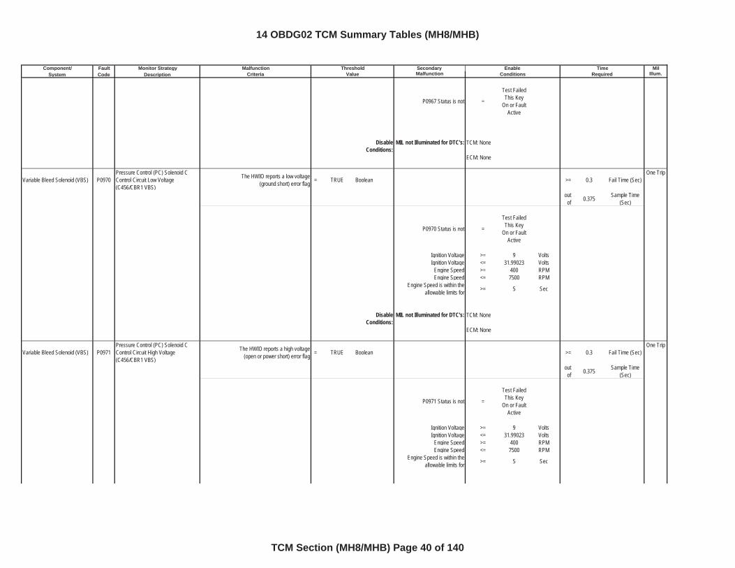
P0967 Status is not =
Test Failed This Key
On or Fault Active
DisableConditions:
MIL not Illuminated for DTC's:
Variable Bleed Solenoid (VBS) P0970Pressure Control (PC) Solenoid C Control Circuit Low Voltage(C456/CBR1 VBS)
The HWIO reports a low voltage (ground short) error flag = TRUE Boolean >= 0.3 Fail Time (Sec)
One Trip
outof 0.375 Sample Time
(Sec)
P0970 Status is not =
Test Failed This Key
On or Fault Active
Ignition Voltage >= 9 VoltsIgnition Voltage <= 31.99023 Volts
Engine Speed >= 400 RPMEngine Speed <= 7500 RPM
Engine Speed is within the allowable limits for >= 5 Sec
DisableConditions:
MIL not Illuminated for DTC's:
Variable Bleed Solenoid (VBS) P0971Pressure Control (PC) Solenoid C Control Circuit High Voltage(C456/CBR1 VBS)
The HWIO reports a high voltage (open or power short) error flag = TRUE Boolean >= 0.3 Fail Time (Sec)
One Trip
outof 0.375 Sample Time
(Sec)
P0971 Status is not =
Test Failed This Key
On or Fault Active
Ignition Voltage >= 9 VoltsIgnition Voltage <= 31.99023 Volts
Engine Speed >= 400 RPMEngine Speed <= 7500 RPM
Engine Speed is within the allowable limits for >= 5 Sec
TCM: None
ECM: None
TCM: None
ECM: None
14 OBDG02 TCM Summary Tables (MH8/MHB)
TCM Section (MH8/MHB) Page 40 of 140
Component/ Fault Monitor Strategy Secondary MilSystem Code Description Malfunction Illum.
Malfunction Threshold Enable TimeCriteria Value Conditions Required
DisableConditions:
MIL not Illuminated for DTC's:
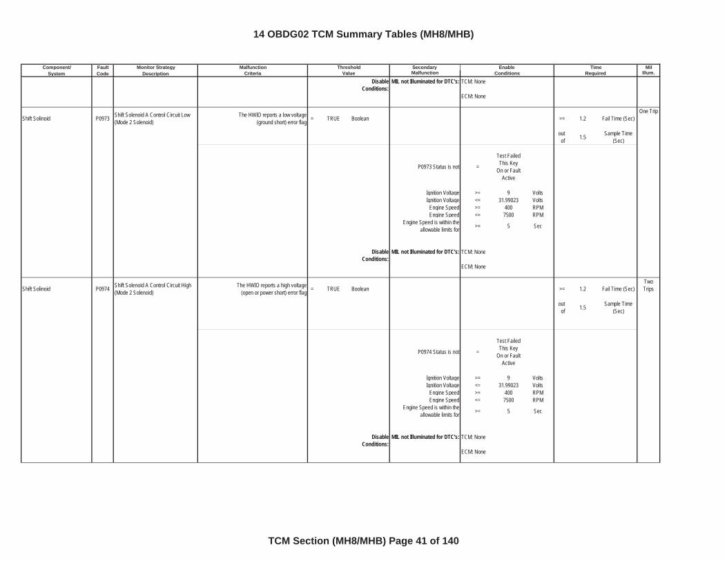
Shift Solinoid P0973 Shift Solenoid A Control Circuit Low(Mode 2 Solenoid)
The HWIO reports a low voltage (ground short) error flag = TRUE Boolean >= 1.2 Fail Time (Sec)
One Trip
outof 1.5 Sample Time
(Sec)
P0973 Status is not =
Test Failed This Key
On or Fault Active
Ignition Voltage >= 9 VoltsIgnition Voltage <= 31.99023 Volts
Engine Speed >= 400 RPMEngine Speed <= 7500 RPM
Engine Speed is within the allowable limits for >= 5 Sec
DisableConditions:
MIL not Illuminated for DTC's:
Shift Solinoid P0974 Shift Solenoid A Control Circuit High(Mode 2 Solenoid)
The HWIO reports a high voltage (open or power short) error flag = TRUE Boolean >= 1.2 Fail Time (Sec)
TwoTrips
outof 1.5 Sample Time
(Sec)
P0974 Status is not =
Test Failed This Key
On or Fault Active
Ignition Voltage >= 9 VoltsIgnition Voltage <= 31.99023 Volts
Engine Speed >= 400 RPMEngine Speed <= 7500 RPM
Engine Speed is within the allowable limits for >= 5 Sec
DisableConditions:
MIL not Illuminated for DTC's:
TCM: None
ECM: None
TCM: None
ECM: None
TCM: None
ECM: None
14 OBDG02 TCM Summary Tables (MH8/MHB)
TCM Section (MH8/MHB) Page 41 of 140
Component/ Fault Monitor Strategy Secondary MilSystem Code Description Malfunction Illum.
Malfunction Threshold Enable TimeCriteria Value Conditions Required
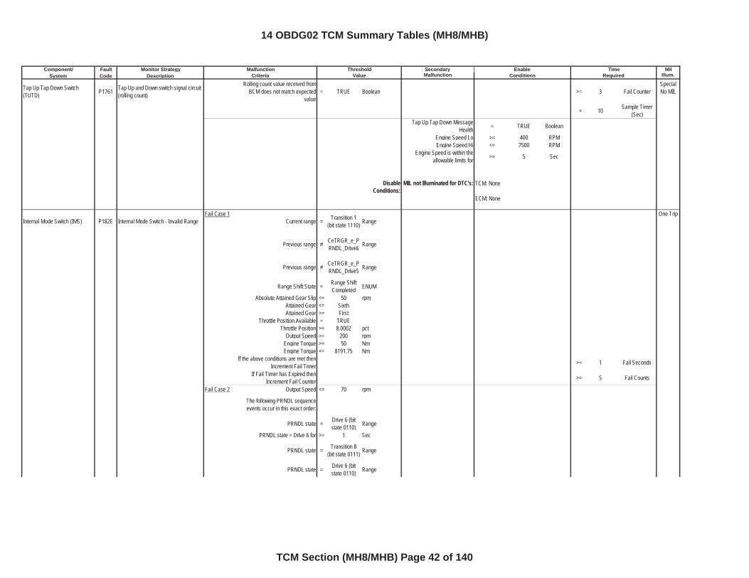
Tap Up Tap Down Switch (TUTD) P1761 Tap Up and Down switch signal circuit
(rolling count)
Rolling count value received from BCM does not match expected
value= TRUE Boolean >= 3 Fail Counter
Special No MIL
> 10 Sample Timer (Sec)
Tap Up Tap Down Message Health = TRUE Boolean
Engine Speed Lo >= 400 RPMEngine Speed Hi <= 7500 RPM
Engine Speed is within the allowable limits for >= 5 Sec
DisableConditions:
MIL not Illuminated for DTC's:
Internal Mode Switch (IMS) P182E Internal Mode Switch - Invalid RangeFail Case 1
Current range = Transition 1 (bit state 1110) Range
One Trip
Previous range CeTRGR_e_PRNDL_Drive6 Range
Previous range CeTRGR_e_PRNDL_Drive5 Range
Range Shift State = Range Shift Completed ENUM
Absolute Attained Gear Slip <= 50 rpmAttained Gear <= SixthAttained Gear >= First
Throttle Position Available = TRUEThrottle Position >= 8.0002 pct
Output Speed >= 200 rpmEngine Torque >= 50 NmEngine Torque <= 8191.75 Nm
If the above conditions are met then Increment Fail Timer >= 1 Fail Seconds
If Fail Timer has Expired then Increment Fail Counter >= 5 Fail Counts
Fail Case 2 Output Speed <= 70 rpm
The following PRNDL sequence events occur in this exact order:
PRNDL state = Drive 6 (bit state 0110) Range
PRNDL state = Drive 6 for >= 1 Sec
PRNDL state = Transition 8 (bit state 0111) Range
PRNDL state = Drive 6 (bit state 0110) Range
TCM: None
ECM: None
14 OBDG02 TCM Summary Tables (MH8/MHB)
TCM Section (MH8/MHB) Page 42 of 140
Component/ Fault Monitor Strategy Secondary MilSystem Code Description Malfunction Illum.
Malfunction Threshold Enable TimeCriteria Value Conditions Required
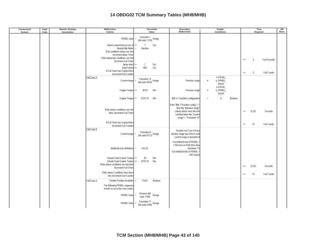
PRNDL state = Transition 1 (bit state 1110) Range
Above sequencing occurs in <= 1 SecNeutral Idle Mode = Inactive
If all conditions above are met Increment delay Timer
If the below two conditions are met Increment Fail Timer >= 3 Fail Seconds
delay timer >= 1 SecInput Speed >= 400 Sec
If Fail Timer has Expired then Increment Fail Counter >= 2 Fail Counts
Fail Case 3Current range = Transition 13
(bit state 0010) Range Previous rangeCeTRGR_e_PRNDL_
Drive5
Engine Torque >= -8192 Nm Previous rangeCeTRGR_e_PRNDL_
Drive5
Engine Torque <= 8191.75 Nm IMS is 7 position configuration = 0 Boolean
If the above conditions are met then, Increment Fail Timer
If the "IMS 7 Position config" = 1 then the "previous range"
criteria above must also be satsified when the "current
range" = "Transition 13"
>= 0.225 Seconds
If Fail Timer has Expired then Increment Fail Counter >= 15 Fail Counts
Fail Case 4
Current range = Transition 8 (bit state 0111) Range
Disable Fail Case 4 if last positive range was Drive 6 and
current range is transition 8
Inhibit bit (see definition) = FALSE
Set inhibit bit true if PRNDL = 1100 (rev) or 0100 (Rev-Neu
transition 11)Set inhibit bit false if PRNDL =
1001 (park)Steady State Engine Torque >= 30 NmSteady State Engine Torque <= 8191.75 Nm
If the above conditions are met then Increment Fail Timer >= 0.225 Seconds
If the above Condtions have been met, Increment Fail Counter >= 15 Fail Counts
Fail Case 5 Throttle Position Available = TRUE Boolean
The following PRNDL sequence events occur in this exact order:
PRNDL State = Reverse (bit state 1100) Range
PRNDL State = Transition 11 (bit state 0100) Range
14 OBDG02 TCM Summary Tables (MH8/MHB)
TCM Section (MH8/MHB) Page 43 of 140
Component/ Fault Monitor Strategy Secondary MilSystem Code Description Malfunction Illum.
Malfunction Threshold Enable TimeCriteria Value Conditions Required
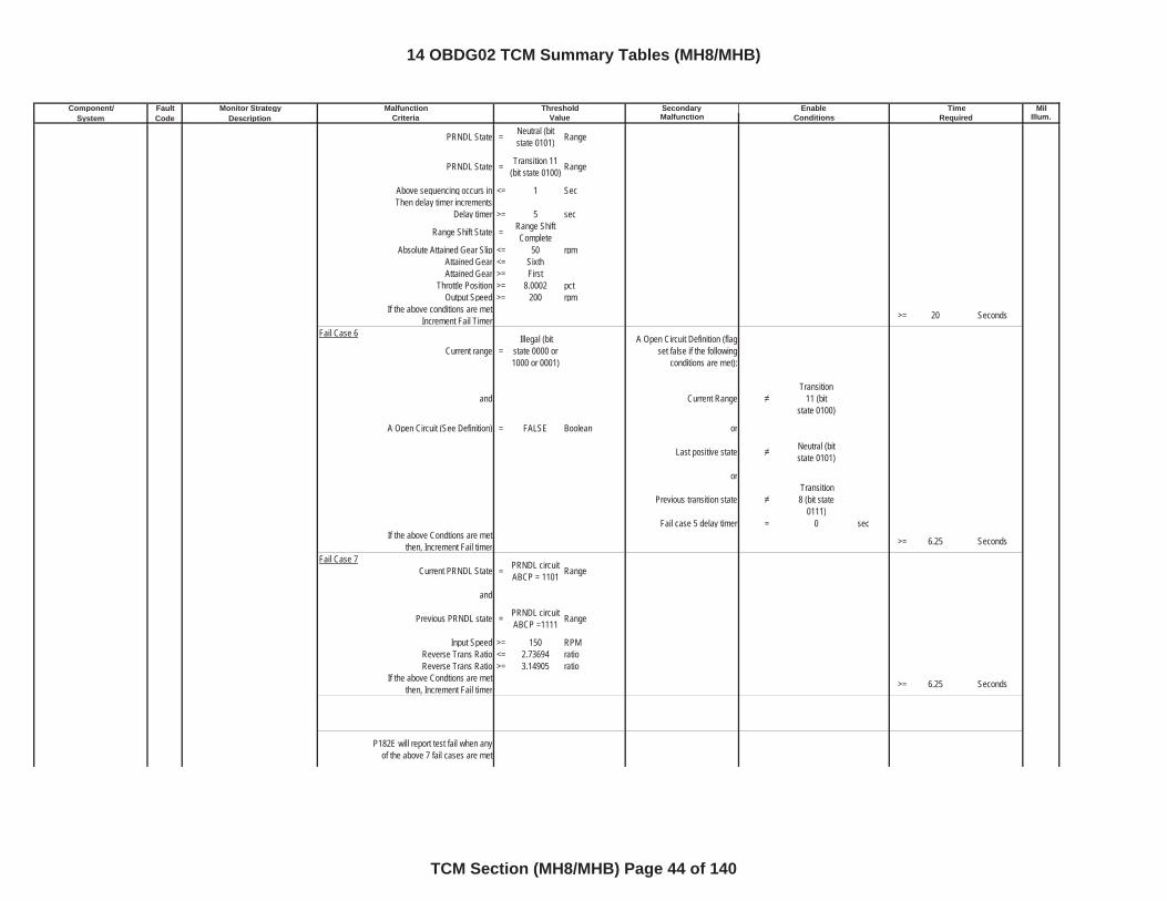
PRNDL State = Neutral (bit state 0101) Range
PRNDL State = Transition 11 (bit state 0100) Range
Above sequencing occurs in <= 1 SecThen delay timer increments
Delay timer >= 5 sec
Range Shift State = Range Shift Complete
Absolute Attained Gear Slip <= 50 rpmAttained Gear <= SixthAttained Gear >= First
Throttle Position >= 8.0002 pctOutput Speed >= 200 rpm
If the above conditions are met Increment Fail Timer >= 20 Seconds
Fail Case 6
Current range = Illegal (bit
state 0000 or 1000 or 0001)
A Open Circuit Definition (flag set false if the following
conditions are met):
and Current RangeTransition
11 (bit state 0100)
A Open Circuit (See Definition) = FALSE Boolean or
Last positive state Neutral (bit state 0101)
or
Previous transition state Transition 8 (bit state
0111)Fail case 5 delay timer = 0 sec
If the above Condtions are met then, Increment Fail timer >= 6.25 Seconds
Fail Case 7Current PRNDL State = PRNDL circuit
ABCP = 1101 Range
and
Previous PRNDL state = PRNDL circuit ABCP =1111 Range
Input Speed >= 150 RPMReverse Trans Ratio <= 2.73694 ratioReverse Trans Ratio >= 3.14905 ratio
If the above Condtions are met then, Increment Fail timer >= 6.25 Seconds
P182E will report test fail when any of the above 7 fail cases are met
14 OBDG02 TCM Summary Tables (MH8/MHB)
TCM Section (MH8/MHB) Page 44 of 140
Component/ Fault Monitor Strategy Secondary MilSystem Code Description Malfunction Illum.
Malfunction Threshold Enable TimeCriteria Value Conditions Required
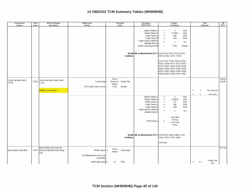
Ignition Voltage Lo >= 9 VoltsIgnition Voltage Hi <= 31.99023 VoltsEngine Speed Lo >= 400 RPMEngine Speed Hi <= 7500 RPM
Engine Speed is within the allowable limits for >= 5 Sec
Engine Torque Signal Valid = TRUE Boolean
DisableConditions:
MIL not Illuminated for DTC's:
Tap Up Tap Down Switch (TUTD) P1876 Tap Up and Down Enable Switch
Circuit Current range =Park or
Reverse or Neutral
Range StateSpecial No MIL
TUTD Enable Switch is Active = TRUE Boolean
UNIQUE to Cruze/Sonic >= 3 Fail Time (Sec)
>= 5 Fail CountsIgnition Voltage Lo >= 9 VoltsIgnition Voltage Hi <= 31.99023 VoltsVehicle Speed Lo <= 511 KPHEngine Speed Lo >= 400 RPMEngine Speed Hi <= 7500 RPM
Engine Speed is within the allowable limits for >= 5 Sec
P1876 Status is
Test Failed This Key
On or Fault Active
DisableConditions:
MIL not Illuminated for DTC's:
Internal Mode Switch (IMS) P1915Internal Mode Switch Does Not Indicate Park/Neutral (P/N) During Start
PRNDL State is Park or Neutral Enumeration
One Trip
The following events must occur Sequentially
Initial Engine speed <= 50 RPM >= 0.1 Enable Time (Sec)
TCM: P0716, P0717, P0722, P0723, P07C0, P07BF, P077C, P077D
ECM: P0101, P0102, P0103, P0106, P0107, P0108, P0171, P0172, P0174, P0175, P0201, P0202, P0203, P0204, P0205, P0206, P0207, P0208, P0300, P0301, P0302, P0303, P0304, P0305, P0306, P0307, P0308, P0401, P042E
TCM: P0815, P0816, P0826, P1761, P1825, P1877, P1915, U0100
ECM: None
14 OBDG02 TCM Summary Tables (MH8/MHB)
TCM Section (MH8/MHB) Page 45 of 140
Component/ Fault Monitor Strategy Secondary MilSystem Code Description Malfunction Illum.
Malfunction Threshold Enable TimeCriteria Value Conditions Required
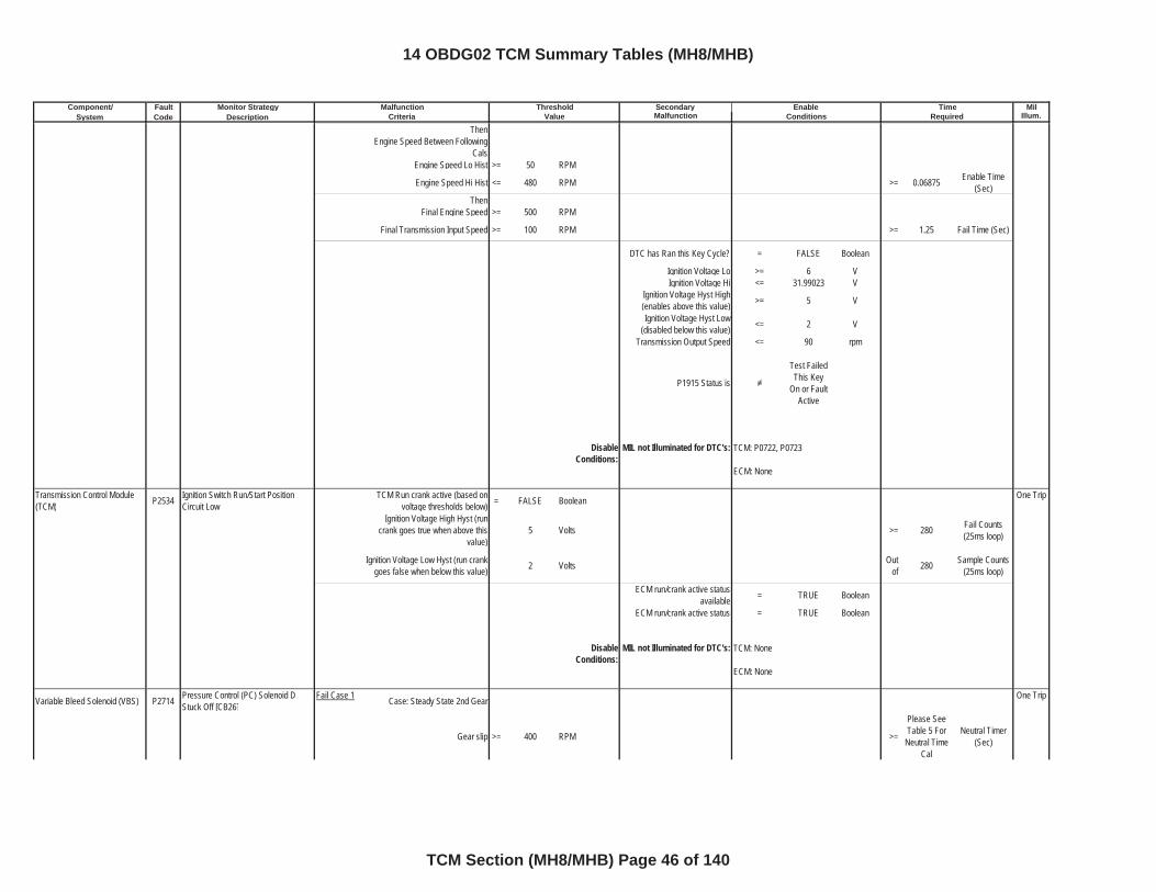
ThenEngine Speed Between Following
Cals Engine Speed Lo Hist >= 50 RPM
Engine Speed Hi Hist <= 480 RPM >= 0.06875 Enable Time (Sec)
ThenFinal Engine Speed >= 500 RPM
Final Transmission Input Speed >= 100 RPM >= 1.25 Fail Time (Sec)
DTC has Ran this Key Cycle? = FALSE Boolean
Ignition Voltage Lo >= 6 VIgnition Voltage Hi <= 31.99023 V
Ignition Voltage Hyst High (enables above this value) >= 5 V
Ignition Voltage Hyst Low (disabled below this value) <= 2 V
Transmission Output Speed <= 90 rpm
P1915 Status is
Test Failed This Key
On or Fault Active
DisableConditions:
MIL not Illuminated for DTC's:
Transmission Control Module (TCM) P2534 Ignition Switch Run/Start Position
Circuit LowTCM Run crank active (based on
voltage thresholds below) = FALSE Boolean One Trip
Ignition Voltage High Hyst (run crank goes true when above this
value)5 Volts >= 280 Fail Counts
(25ms loop)
Ignition Voltage Low Hyst (run crank goes false when below this value) 2 Volts Out
of 280 Sample Counts (25ms loop)
ECM run/crank active status available = TRUE Boolean
ECM run/crank active status = TRUE Boolean
DisableConditions:
MIL not Illuminated for DTC's:
Variable Bleed Solenoid (VBS) P2714 Pressure Control (PC) Solenoid D Stuck Off [CB26]
Fail Case 1 Case: Steady State 2nd Gear One Trip
Gear slip >= 400 RPM >=
Please See Table 5 For
Neutral Time Cal
Neutral Timer (Sec)
TCM: P0722, P0723
ECM: None
TCM: None
ECM: None
14 OBDG02 TCM Summary Tables (MH8/MHB)
TCM Section (MH8/MHB) Page 46 of 140
Component/ Fault Monitor Strategy Secondary MilSystem Code Description Malfunction Illum.
Malfunction Threshold Enable TimeCriteria Value Conditions Required
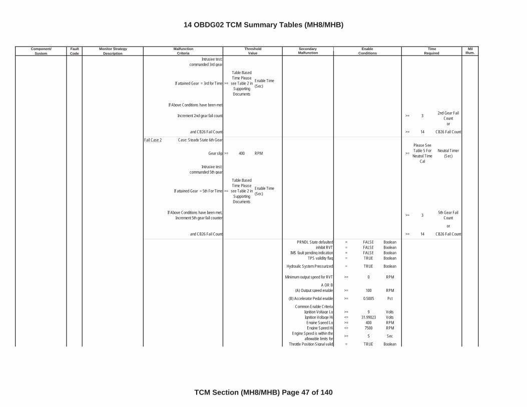
Intrusive test:commanded 3rd gear
If attained Gear = 3rd for Time >=
Table Based Time Please
see Table 2 in SupportingDocuments
Enable Time (Sec)
If Above Conditions have been met
Increment 2nd gear fail count >= 3 2nd Gear Fail Count
or
and CB26 Fail Count >= 14 CB26 Fail Count
Fail Case 2 Case: Steady State 6th Gear
Gear slip >= 400 RPM >=
Please See Table 5 For
Neutral Time Cal
Neutral Timer (Sec)
Intrusive test:commanded 5th gear
If attained Gear = 5th For Time >=
Table Based Time Please
see Table 2 in SupportingDocuments
Enable Time (Sec)
If Above Conditions have been met, Increment 5th gear fail counter >= 3 5th Gear Fail
Count
or
and CB26 Fail Count >= 14 CB26 Fail Count
PRNDL State defaulted = FALSE Booleaninhibit RVT = FALSE Boolean
IMS fault pending indication = FALSE BooleanTPS validity flag = TRUE Boolean
Hydraulic System Pressurized = TRUE Boolean
Minimum output speed for RVT >= 0 RPM
A OR B(A) Output speed enable >= 100 RPM
(B) Accelerator Pedal enable >= 0.5005 Pct
Common Enable CriteriaIgnition Voltage Lo >= 9 VoltsIgnition Voltage Hi <= 31.99023 VoltsEngine Speed Lo >= 400 RPMEngine Speed Hi <= 7500 RPM
Engine Speed is within the allowable limits for >= 5 Sec
Throttle Position Signal valid = TRUE Boolean
14 OBDG02 TCM Summary Tables (MH8/MHB)
TCM Section (MH8/MHB) Page 47 of 140
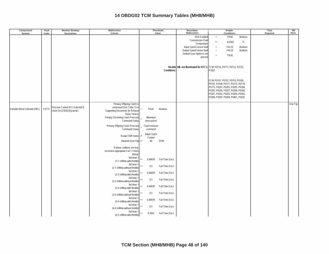
Component/ Fault Monitor Strategy Secondary MilSystem Code Description Malfunction Illum.
Malfunction Threshold Enable TimeCriteria Value Conditions Required
HSD Enabled = TRUE BooleanTransmission Fluid
Temperature >= -6.6563 ºC
Input Speed Sensor fault = FALSE BooleanOutput Speed Sensor fault = FALSE BooleanDefault Gear Option is not
present = TRUE
DisableConditions:
MIL not Illuminated for DTC's:
Variable Bleed Solenoid (VBS) P2715 Pressure Control (PC) Solenoid D Stuck On [CB26] (Dynamic)
Primary Offgoing Clutch is exhausted (See Table 13 in
Supporting Documents for Exhaust Delay Timers)
= TRUE Boolean
One Trip
Primary Oncoming Clutch Pressure Command Status = Maximum
pressurized
Primary Offgoing Clutch Pressure Command Status = Clutch exhaust
command
Range Shift Status Initial Clutch Control
Attained Gear Slip <= 40 RPM
If above coditons are true, increment appropriate Fail 1 Timers
Below:fail timer 1
(2-1 shifting with throttle) >= 0.40039 Fail Time (Sec)
fail timer 1(2-1 shifting without throttle) >= 0.5 Fail Time (Sec)
fail timer 1(2-3 shifting with throttle) >= 0.40039 Fail Time (Sec)
fail timer 1(2-3 shifting without throttle) >= 0.5 Fail Time (Sec)
fail timer 1(2-4 shifting with throttle) >= 0.40039 Fail Time (Sec)
fail timer 1(2-4 shifting without throttle) >= 0.5 Fail Time (Sec)
fail timer 1(6-4 shifting with throttle) >= 0.40039 Fail Time (Sec)
fail timer 1(6-4 shifting without throttle) >= 0.5 Fail Time (Sec)
fail timer 1(6-5 shifting with throttle) >= 0.7002 Fail Time (Sec)
TCM: P0716, P0717, P0722, P0723, P182E
ECM: P0101, P0102, P0103, P0106, P0107, P0108, P0171, P0172, P0174, P0175, P0201, P0202, P0203, P0204, P0205, P0206, P0207, P0208, P0300, P0301, P0302, P0303, P0304, P0305, P0306, P0307, P0308, P0401, P042E
14 OBDG02 TCM Summary Tables (MH8/MHB)
TCM Section (MH8/MHB) Page 48 of 140
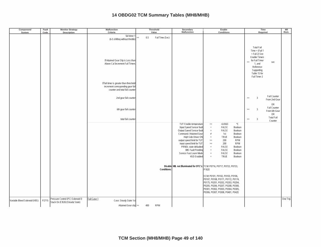
Component/ Fault Monitor Strategy Secondary MilSystem Code Description Malfunction Illum.
Malfunction Threshold Enable TimeCriteria Value Conditions Required
fail timer 1(6-5 shifting without throttle) >= 0.5 Fail Time (Sec)
If Attained Gear Slip is Less than Above Cal Increment Fail Timers >=
Total Fail Time = (Fail 1 + Fail 2) See
Enable Timers for Fail Timer
1, and ReferenceSupportingTable 15 for Fail Timer 2
sec
If fail timer is greater than threshold increment corresponding gear fail
counter and total fail counter
2nd gear fail counter >= 3 Fail Counter From 2nd Gear
OR
6th gear fail counter >= 3 Fail Counter From 6th Gear
OR
total fail counter >= 3 Total Fail Counter
TUT Enable temperature >= -6.6563 ºCInput Speed Sensor fault = FALSE Boolean
Output Speed Sensor fault = FALSE BooleanCommand / Attained Gear 1st Boolean
High Side Driver ON = TRUE Booleanoutput speed limit for TUT >= 200 RPM
input speed limit for TUT >= 200 RPMPRNDL state defaulted = FALSE Boolean
IMS Fault Pending = FALSE BooleanService Fast Learn Mode = FALSE Boolean
HSD Enabled = TRUE Boolean
DisableConditions:
MIL not Illuminated for DTC's:
Variable Bleed Solenoid (VBS) P2715 Pressure Control (PC) Solenoid D Stuck On [CB26] (Steady State)
Fail Case 1 Case: Steady State 1st One Trip
Attained Gear slip >= 400 RPM
TCM: P0716, P0717, P0722, P0723, P182E
ECM: P0101, P0102, P0103, P0106, P0107, P0108, P0171, P0172, P0174, P0175, P0201, P0202, P0203, P0204, P0205, P0206, P0207, P0208, P0300, P0301, P0302, P0303, P0304, P0305, P0306, P0307, P0308, P0401, P042E
14 OBDG02 TCM Summary Tables (MH8/MHB)
TCM Section (MH8/MHB) Page 49 of 140
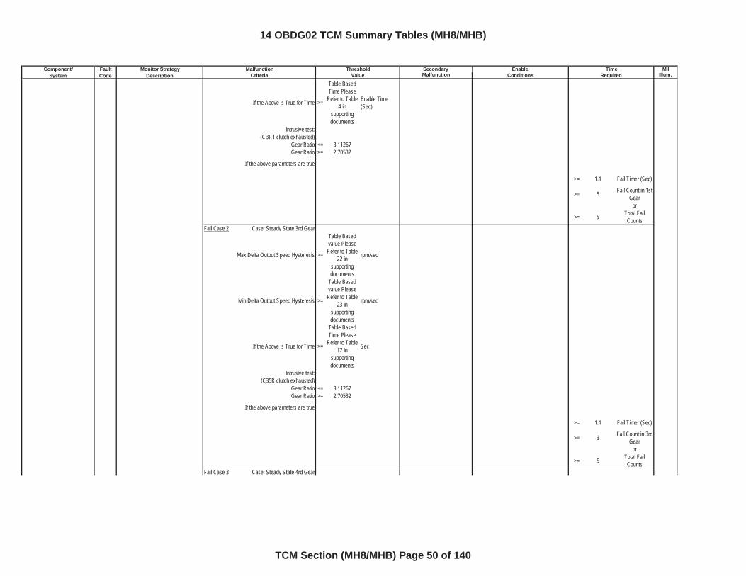
Component/ Fault Monitor Strategy Secondary MilSystem Code Description Malfunction Illum.
Malfunction Threshold Enable TimeCriteria Value Conditions Required
If the Above is True for Time >=
Table Based Time Please
Refer to Table 4 in
supportingdocuments
Enable Time (Sec)
Intrusive test:(CBR1 clutch exhausted)
Gear Ratio <= 3.11267Gear Ratio >= 2.70532
If the above parameters are true
>= 1.1 Fail Timer (Sec)
>= 5 Fail Count in 1st Gear
or
>= 5 Total Fail Counts
Fail Case 2 Case: Steady State 3rd Gear
Max Delta Output Speed Hysteresis >=
Table Based value Please
Refer to Table 22 in
supportingdocuments
rpm/sec
Min Delta Output Speed Hysteresis >=
Table Based value Please
Refer to Table 23 in
supportingdocuments
rpm/sec
If the Above is True for Time >=
Table Based Time Please
Refer to Table 17 in
supportingdocuments
Sec
Intrusive test: (C35R clutch exhausted)
Gear Ratio <= 3.11267Gear Ratio >= 2.70532
If the above parameters are true
>= 1.1 Fail Timer (Sec)
>= 3 Fail Count in 3rd Gear
or
>= 5 Total Fail Counts
Fail Case 3 Case: Steady State 4rd Gear
14 OBDG02 TCM Summary Tables (MH8/MHB)
TCM Section (MH8/MHB) Page 50 of 140
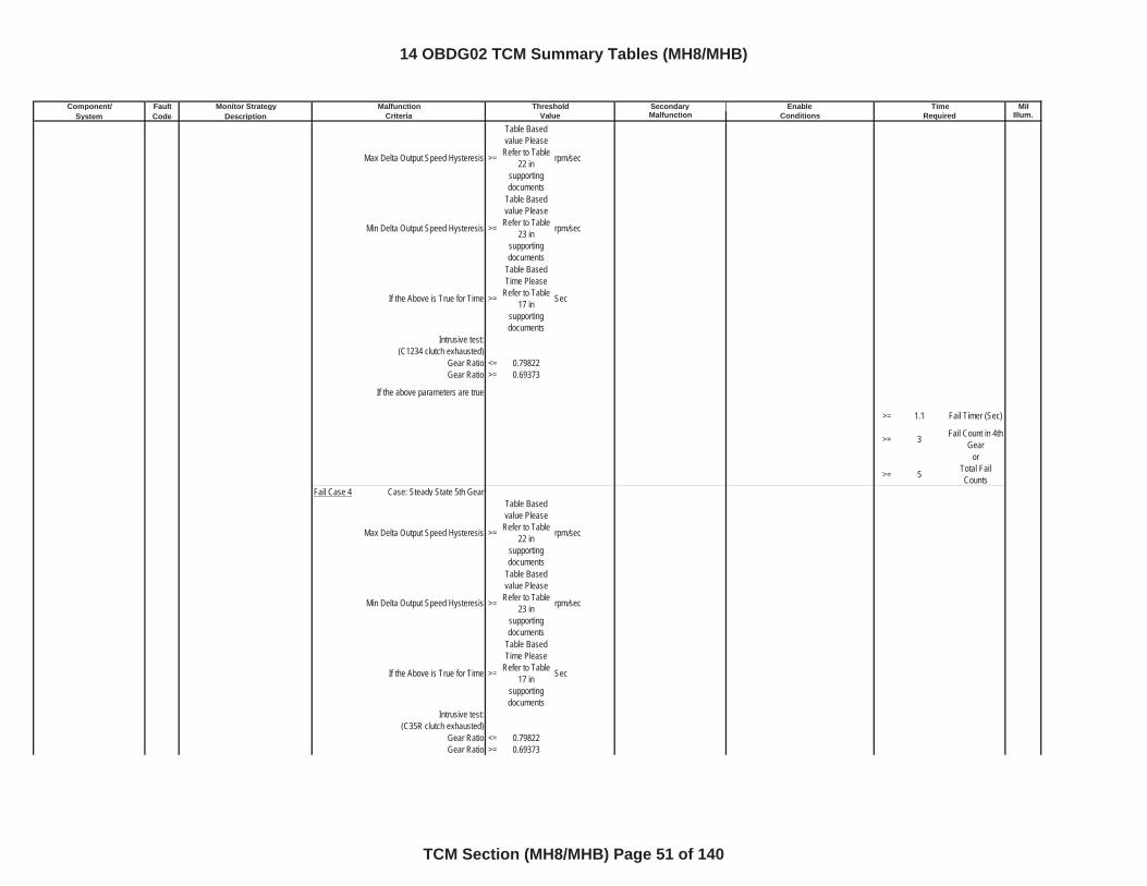
Component/ Fault Monitor Strategy Secondary MilSystem Code Description Malfunction Illum.
Malfunction Threshold Enable TimeCriteria Value Conditions Required
Max Delta Output Speed Hysteresis >=
Table Based value Please
Refer to Table 22 in
supportingdocuments
rpm/sec
Min Delta Output Speed Hysteresis >=
Table Based value Please
Refer to Table 23 in
supportingdocuments
rpm/sec
If the Above is True for Time >=
Table Based Time Please
Refer to Table 17 in
supportingdocuments
Sec
Intrusive test: (C1234 clutch exhausted)
Gear Ratio <= 0.79822Gear Ratio >= 0.69373
If the above parameters are true
>= 1.1 Fail Timer (Sec)
>= 3 Fail Count in 4th Gear
or
>= 5 Total Fail Counts
Fail Case 4 Case: Steady State 5th Gear
Max Delta Output Speed Hysteresis >=
Table Based value Please
Refer to Table 22 in
supportingdocuments
rpm/sec
Min Delta Output Speed Hysteresis >=
Table Based value Please
Refer to Table 23 in
supportingdocuments
rpm/sec
If the Above is True for Time >=
Table Based Time Please
Refer to Table 17 in
supportingdocuments
Sec
Intrusive test: (C35R clutch exhausted)
Gear Ratio <= 0.79822Gear Ratio >= 0.69373
14 OBDG02 TCM Summary Tables (MH8/MHB)
TCM Section (MH8/MHB) Page 51 of 140
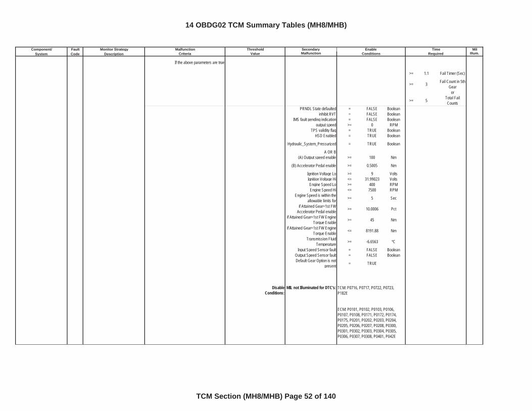
Component/ Fault Monitor Strategy Secondary MilSystem Code Description Malfunction Illum.
Malfunction Threshold Enable TimeCriteria Value Conditions Required
If the above parameters are true
>= 1.1 Fail Timer (Sec)
>= 3 Fail Count in 5th Gear
or
>= 5 Total Fail Counts
PRNDL State defaulted = FALSE Booleaninhibit RVT = FALSE Boolean
IMS fault pending indication = FALSE Booleanoutput speed >= 0 RPM
TPS validity flag = TRUE BooleanHSD Enabled = TRUE Boolean
Hydraulic_System_Pressurized = TRUE Boolean
A OR B(A) Output speed enable >= 100 Nm
(B) Accelerator Pedal enable >= 0.5005 Nm
Ignition Voltage Lo >= 9 VoltsIgnition Voltage Hi <= 31.99023 VoltsEngine Speed Lo >= 400 RPMEngine Speed Hi <= 7500 RPM
Engine Speed is within the allowable limits for >= 5 Sec
if Attained Gear=1st FW Accelerator Pedal enable >= 10.0006 Pct
if Attained Gear=1st FW Engine Torque Enable >= 45 Nm
if Attained Gear=1st FW Engine Torque Enable <= 8191.88 Nm
Transmission Fluid Temperature >= -6.6563 ºC
Input Speed Sensor fault = FALSE BooleanOutput Speed Sensor fault = FALSE BooleanDefault Gear Option is not
present = TRUE
DisableConditions:
MIL not Illuminated for DTC's: TCM: P0716, P0717, P0722, P0723, P182E
ECM: P0101, P0102, P0103, P0106, P0107, P0108, P0171, P0172, P0174, P0175, P0201, P0202, P0203, P0204, P0205, P0206, P0207, P0208, P0300, P0301, P0302, P0303, P0304, P0305, P0306, P0307, P0308, P0401, P042E
14 OBDG02 TCM Summary Tables (MH8/MHB)
TCM Section (MH8/MHB) Page 52 of 140
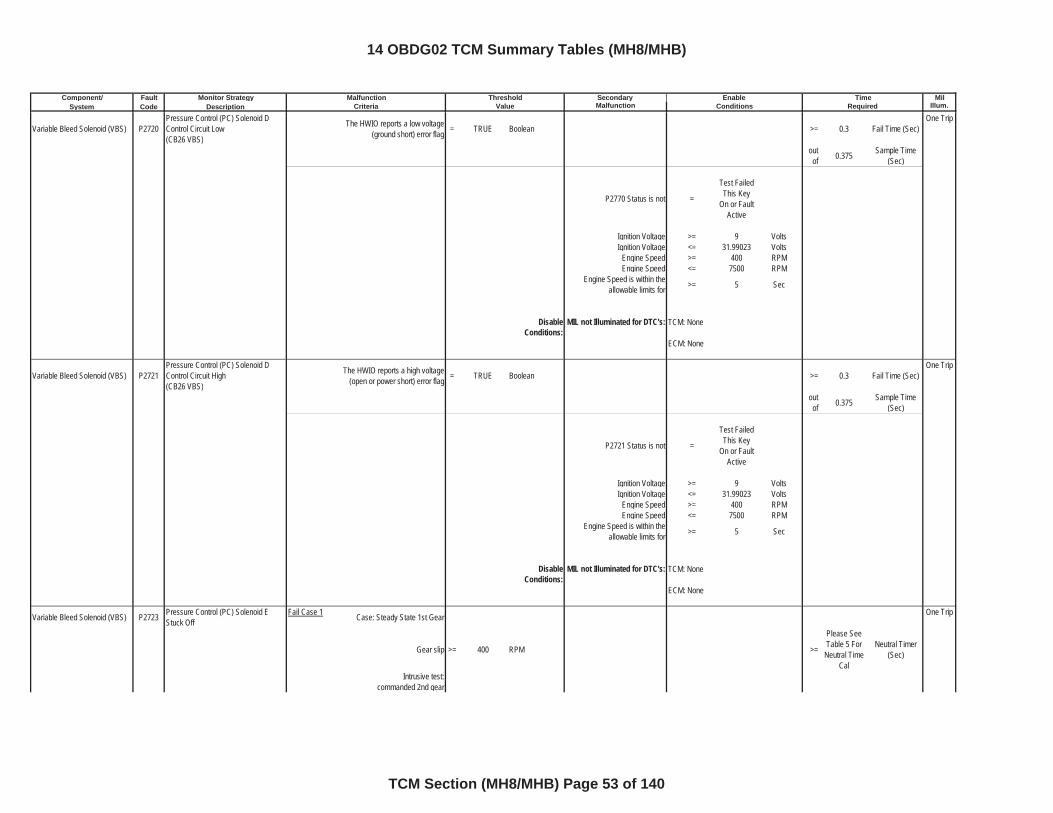
Component/ Fault Monitor Strategy Secondary MilSystem Code Description Malfunction Illum.
Malfunction Threshold Enable TimeCriteria Value Conditions Required
Variable Bleed Solenoid (VBS) P2720Pressure Control (PC) Solenoid D Control Circuit Low(CB26 VBS)
The HWIO reports a low voltage (ground short) error flag = TRUE Boolean >= 0.3 Fail Time (Sec)
One Trip
outof 0.375 Sample Time
(Sec)
P2770 Status is not =
Test Failed This Key
On or Fault Active
Ignition Voltage >= 9 VoltsIgnition Voltage <= 31.99023 Volts
Engine Speed >= 400 RPMEngine Speed <= 7500 RPM
Engine Speed is within the allowable limits for >= 5 Sec
DisableConditions:
MIL not Illuminated for DTC's:
Variable Bleed Solenoid (VBS) P2721Pressure Control (PC) Solenoid D Control Circuit High(CB26 VBS)
The HWIO reports a high voltage (open or power short) error flag = TRUE Boolean >= 0.3 Fail Time (Sec)
One Trip
outof 0.375 Sample Time
(Sec)
P2721 Status is not =
Test Failed This Key
On or Fault Active
Ignition Voltage >= 9 VoltsIgnition Voltage <= 31.99023 Volts
Engine Speed >= 400 RPMEngine Speed <= 7500 RPM
Engine Speed is within the allowable limits for >= 5 Sec
DisableConditions:
MIL not Illuminated for DTC's:
Variable Bleed Solenoid (VBS) P2723 Pressure Control (PC) Solenoid E Stuck Off
Fail Case 1 Case: Steady State 1st Gear One Trip
Gear slip >= 400 RPM >=
Please See Table 5 For
Neutral Time Cal
Neutral Timer (Sec)
Intrusive test:commanded 2nd gear
TCM: None
ECM: None
TCM: None
ECM: None
14 OBDG02 TCM Summary Tables (MH8/MHB)
TCM Section (MH8/MHB) Page 53 of 140
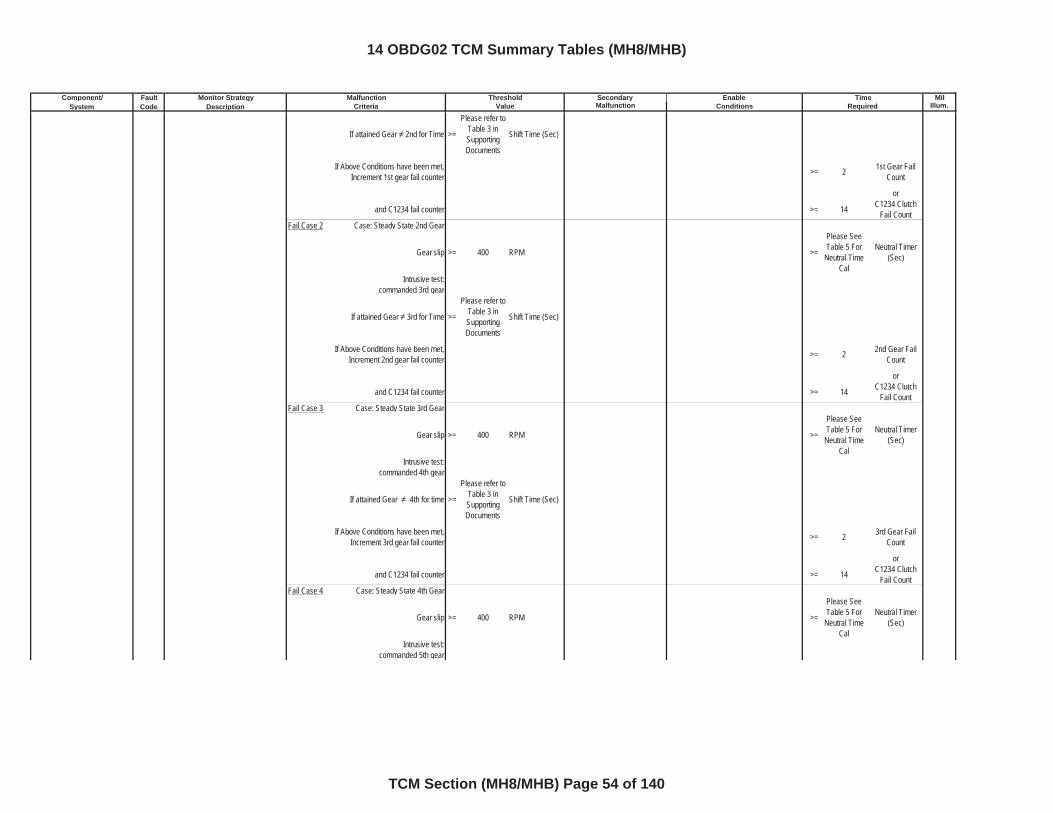
Component/ Fault Monitor Strategy Secondary MilSystem Code Description Malfunction Illum.
Malfunction Threshold Enable TimeCriteria Value Conditions Required
If attained Gear 2nd for Time >=
Please refer to Table 3 in SupportingDocuments
Shift Time (Sec)
If Above Conditions have been met, Increment 1st gear fail counter >= 2 1st Gear Fail
Count
or
and C1234 fail counter >= 14 C1234 Clutch Fail Count
Fail Case 2 Case: Steady State 2nd Gear
Gear slip >= 400 RPM >=
Please See Table 5 For
Neutral Time Cal
Neutral Timer (Sec)
Intrusive test:commanded 3rd gear
If attained Gear 3rd for Time >=
Please refer to Table 3 in SupportingDocuments
Shift Time (Sec)
If Above Conditions have been met, Increment 2nd gear fail counter >= 2 2nd Gear Fail
Count
or
and C1234 fail counter >= 14 C1234 Clutch Fail Count
Fail Case 3 Case: Steady State 3rd Gear
Gear slip >= 400 RPM >=
Please See Table 5 For
Neutral Time Cal
Neutral Timer (Sec)
Intrusive test:commanded 4th gear
If attained Gear 4th for time >=
Please refer to Table 3 in SupportingDocuments
Shift Time (Sec)
If Above Conditions have been met, Increment 3rd gear fail counter >= 2 3rd Gear Fail
Count
or
and C1234 fail counter >= 14 C1234 Clutch Fail Count
Fail Case 4 Case: Steady State 4th Gear
Gear slip >= 400 RPM >=
Please See Table 5 For
Neutral Time Cal
Neutral Timer (Sec)
Intrusive test:commanded 5th gear
14 OBDG02 TCM Summary Tables (MH8/MHB)
TCM Section (MH8/MHB) Page 54 of 140
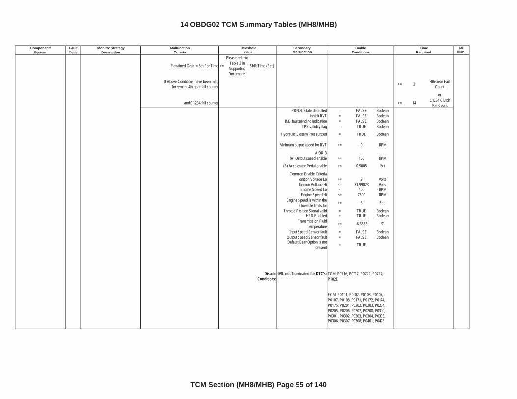
Component/ Fault Monitor Strategy Secondary MilSystem Code Description Malfunction Illum.
Malfunction Threshold Enable TimeCriteria Value Conditions Required
If attained Gear = 5th For Time >=
Please refer to Table 3 in SupportingDocuments
Shift Time (Sec)
If Above Conditions have been met, Increment 4th gear fail counter >= 3 4th Gear Fail
Count
or
and C1234 fail counter >= 14 C1234 Clutch Fail Count
PRNDL State defaulted = FALSE Booleaninhibit RVT = FALSE Boolean
IMS fault pending indication = FALSE BooleanTPS validity flag = TRUE Boolean
Hydraulic System Pressurized = TRUE Boolean
Minimum output speed for RVT >= 0 RPM
A OR B(A) Output speed enable >= 100 RPM
(B) Accelerator Pedal enable >= 0.5005 Pct
Common Enable CriteriaIgnition Voltage Lo >= 9 VoltsIgnition Voltage Hi <= 31.99023 VoltsEngine Speed Lo >= 400 RPMEngine Speed Hi <= 7500 RPM
Engine Speed is within the allowable limits for >= 5 Sec
Throttle Position Signal valid = TRUE BooleanHSD Enabled = TRUE Boolean
Transmission Fluid Temperature >= -6.6563 ºC
Input Speed Sensor fault = FALSE BooleanOutput Speed Sensor fault = FALSE BooleanDefault Gear Option is not
present = TRUE
DisableConditions:
MIL not Illuminated for DTC's: TCM: P0716, P0717, P0722, P0723, P182E
ECM: P0101, P0102, P0103, P0106, P0107, P0108, P0171, P0172, P0174, P0175, P0201, P0202, P0203, P0204, P0205, P0206, P0207, P0208, P0300, P0301, P0302, P0303, P0304, P0305, P0306, P0307, P0308, P0401, P042E
14 OBDG02 TCM Summary Tables (MH8/MHB)
TCM Section (MH8/MHB) Page 55 of 140
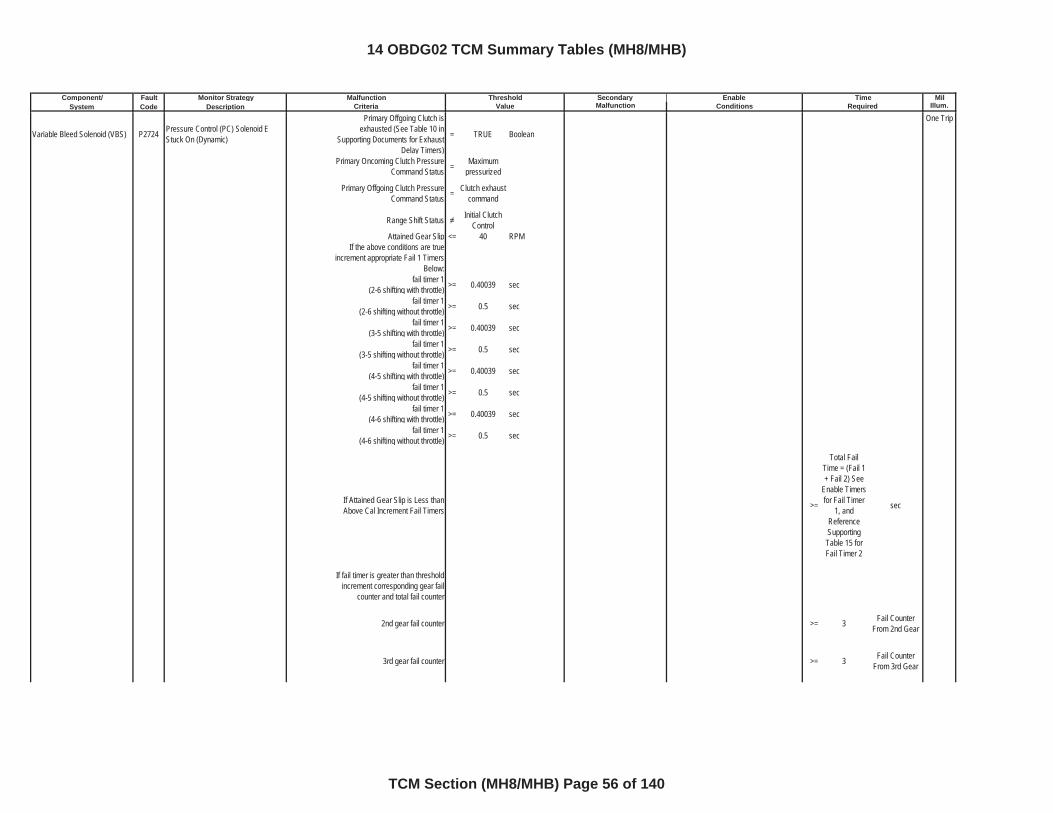
Component/ Fault Monitor Strategy Secondary MilSystem Code Description Malfunction Illum.
Malfunction Threshold Enable TimeCriteria Value Conditions Required
Variable Bleed Solenoid (VBS) P2724 Pressure Control (PC) Solenoid E Stuck On (Dynamic)
Primary Offgoing Clutch is exhausted (See Table 10 in
Supporting Documents for Exhaust Delay Timers)
= TRUE Boolean
One Trip
Primary Oncoming Clutch Pressure Command Status = Maximum
pressurized
Primary Offgoing Clutch Pressure Command Status = Clutch exhaust
command
Range Shift Status Initial Clutch Control
Attained Gear Slip <= 40 RPMIf the above conditions are true
increment appropriate Fail 1 Timers Below:
fail timer 1(2-6 shifting with throttle) >= 0.40039 sec
fail timer 1(2-6 shifting without throttle) >= 0.5 sec
fail timer 1(3-5 shifting with throttle) >= 0.40039 sec
fail timer 1(3-5 shifting without throttle) >= 0.5 sec
fail timer 1(4-5 shifting with throttle) >= 0.40039 sec
fail timer 1(4-5 shifting without throttle) >= 0.5 sec
fail timer 1(4-6 shifting with throttle) >= 0.40039 sec
fail timer 1(4-6 shifting without throttle) >= 0.5 sec
If Attained Gear Slip is Less than Above Cal Increment Fail Timers >=
Total Fail Time = (Fail 1 + Fail 2) See
Enable Timers for Fail Timer
1, and ReferenceSupportingTable 15 for Fail Timer 2
sec
If fail timer is greater than threshold increment corresponding gear fail
counter and total fail counter
2nd gear fail counter >= 3 Fail Counter From 2nd Gear
3rd gear fail counter >= 3 Fail Counter From 3rd Gear
14 OBDG02 TCM Summary Tables (MH8/MHB)
TCM Section (MH8/MHB) Page 56 of 140
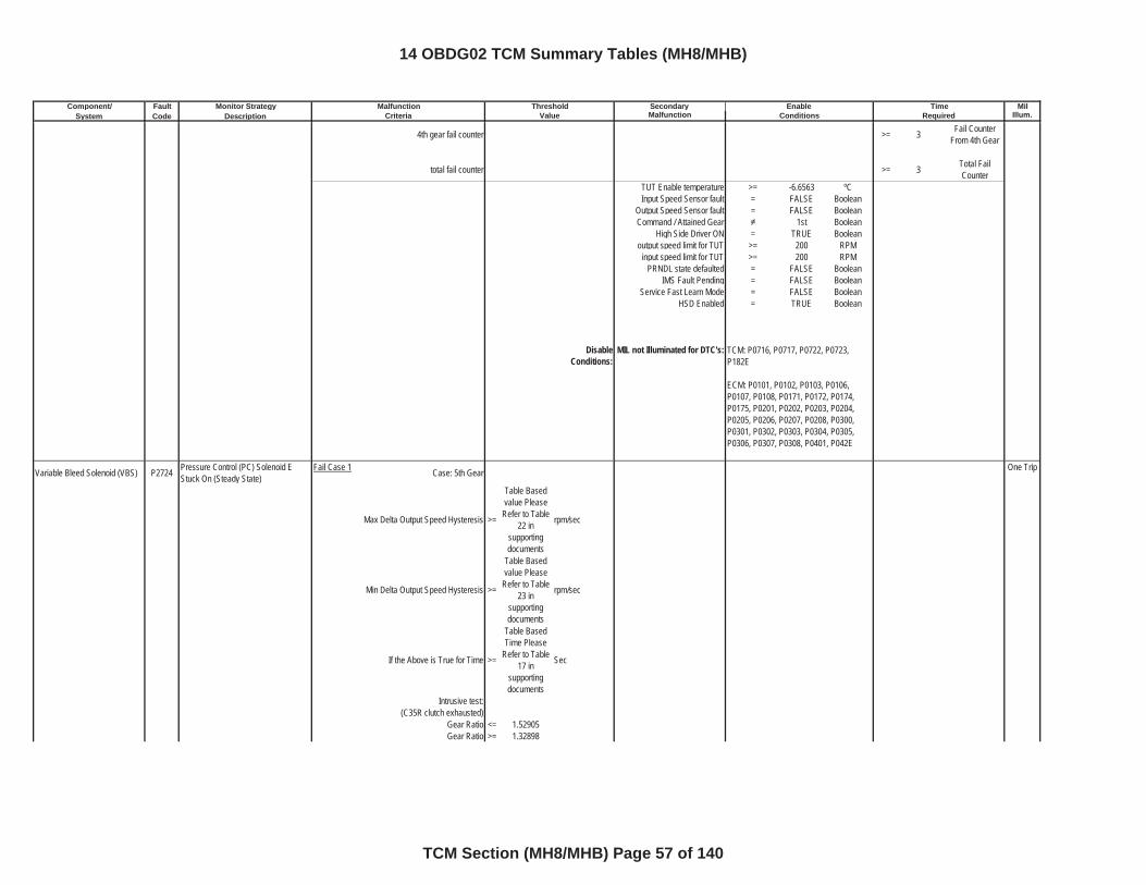
Component/ Fault Monitor Strategy Secondary MilSystem Code Description Malfunction Illum.
Malfunction Threshold Enable TimeCriteria Value Conditions Required
4th gear fail counter >= 3 Fail Counter From 4th Gear
total fail counter >= 3 Total Fail Counter
TUT Enable temperature >= -6.6563 ºCInput Speed Sensor fault = FALSE Boolean
Output Speed Sensor fault = FALSE BooleanCommand / Attained Gear 1st Boolean
High Side Driver ON = TRUE Booleanoutput speed limit for TUT >= 200 RPM
input speed limit for TUT >= 200 RPMPRNDL state defaulted = FALSE Boolean
IMS Fault Pending = FALSE BooleanService Fast Learn Mode = FALSE Boolean
HSD Enabled = TRUE Boolean
DisableConditions:
MIL not Illuminated for DTC's:
Variable Bleed Solenoid (VBS) P2724 Pressure Control (PC) Solenoid E Stuck On (Steady State)
Fail Case 1 Case: 5th Gear One Trip
Max Delta Output Speed Hysteresis >=
Table Based value Please
Refer to Table 22 in
supportingdocuments
rpm/sec
Min Delta Output Speed Hysteresis >=
Table Based value Please
Refer to Table 23 in
supportingdocuments
rpm/sec
If the Above is True for Time >=
Table Based Time Please
Refer to Table 17 in
supportingdocuments
Sec
Intrusive test:(C35R clutch exhausted)
Gear Ratio <= 1.52905Gear Ratio >= 1.32898
TCM: P0716, P0717, P0722, P0723, P182E
ECM: P0101, P0102, P0103, P0106, P0107, P0108, P0171, P0172, P0174, P0175, P0201, P0202, P0203, P0204, P0205, P0206, P0207, P0208, P0300, P0301, P0302, P0303, P0304, P0305, P0306, P0307, P0308, P0401, P042E
14 OBDG02 TCM Summary Tables (MH8/MHB)
TCM Section (MH8/MHB) Page 57 of 140
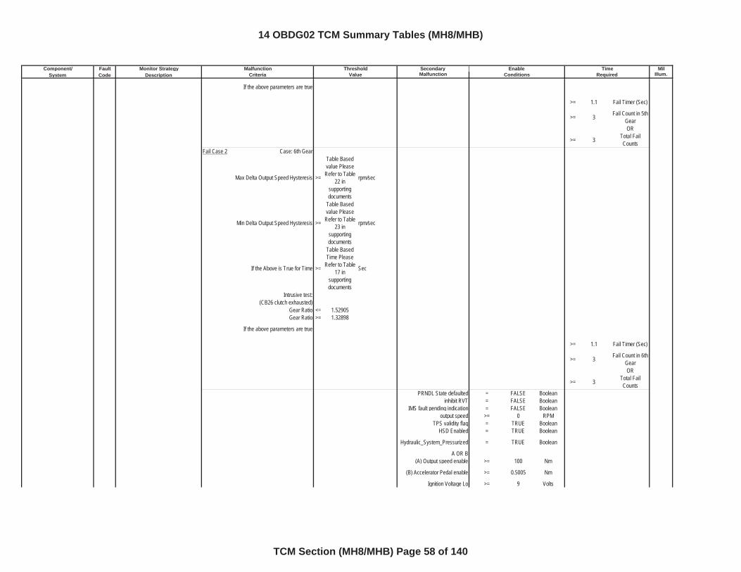
Component/ Fault Monitor Strategy Secondary MilSystem Code Description Malfunction Illum.
Malfunction Threshold Enable TimeCriteria Value Conditions Required
If the above parameters are true
>= 1.1 Fail Timer (Sec)
>= 3 Fail Count in 5th GearOR
>= 3 Total Fail Counts
Fail Case 2 Case: 6th Gear
Max Delta Output Speed Hysteresis >=
Table Based value Please
Refer to Table 22 in
supportingdocuments
rpm/sec
Min Delta Output Speed Hysteresis >=
Table Based value Please
Refer to Table 23 in
supportingdocuments
rpm/sec
If the Above is True for Time >=
Table Based Time Please
Refer to Table 17 in
supportingdocuments
Sec
Intrusive test:(CB26 clutch exhausted)
Gear Ratio <= 1.52905Gear Ratio >= 1.32898
If the above parameters are true
>= 1.1 Fail Timer (Sec)
>= 3 Fail Count in 6th GearOR
>= 3 Total Fail Counts
PRNDL State defaulted = FALSE Booleaninhibit RVT = FALSE Boolean
IMS fault pending indication = FALSE Booleanoutput speed >= 0 RPM
TPS validity flag = TRUE BooleanHSD Enabled = TRUE Boolean
Hydraulic_System_Pressurized = TRUE Boolean
A OR B(A) Output speed enable >= 100 Nm
(B) Accelerator Pedal enable >= 0.5005 Nm
Ignition Voltage Lo >= 9 Volts
14 OBDG02 TCM Summary Tables (MH8/MHB)
TCM Section (MH8/MHB) Page 58 of 140
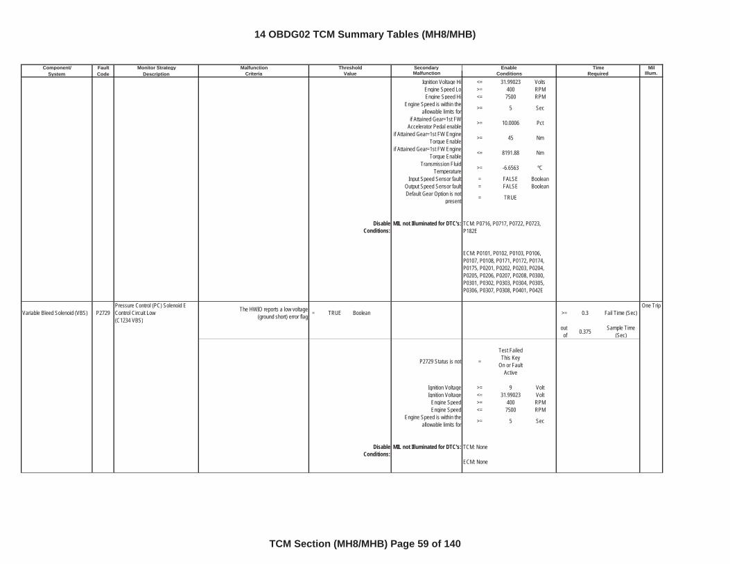
Component/ Fault Monitor Strategy Secondary MilSystem Code Description Malfunction Illum.
Malfunction Threshold Enable TimeCriteria Value Conditions Required
Ignition Voltage Hi <= 31.99023 VoltsEngine Speed Lo >= 400 RPMEngine Speed Hi <= 7500 RPM
Engine Speed is within the allowable limits for >= 5 Sec
if Attained Gear=1st FW Accelerator Pedal enable >= 10.0006 Pct
if Attained Gear=1st FW Engine Torque Enable >= 45 Nm
if Attained Gear=1st FW Engine Torque Enable <= 8191.88 Nm
Transmission Fluid Temperature >= -6.6563 ºC
Input Speed Sensor fault = FALSE BooleanOutput Speed Sensor fault = FALSE BooleanDefault Gear Option is not
present = TRUE
DisableConditions:
MIL not Illuminated for DTC's:
Variable Bleed Solenoid (VBS) P2729Pressure Control (PC) Solenoid E Control Circuit Low(C1234 VBS)
The HWIO reports a low voltage (ground short) error flag = TRUE Boolean >= 0.3 Fail Time (Sec)
One Trip
outof 0.375 Sample Time
(Sec)
P2729 Status is not =
Test Failed This Key
On or Fault Active
Ignition Voltage >= 9 VoltIgnition Voltage <= 31.99023 Volt
Engine Speed >= 400 RPMEngine Speed <= 7500 RPM
Engine Speed is within the allowable limits for >= 5 Sec
DisableConditions:
MIL not Illuminated for DTC's:
TCM: P0716, P0717, P0722, P0723, P182E
ECM: P0101, P0102, P0103, P0106, P0107, P0108, P0171, P0172, P0174, P0175, P0201, P0202, P0203, P0204, P0205, P0206, P0207, P0208, P0300, P0301, P0302, P0303, P0304, P0305, P0306, P0307, P0308, P0401, P042E
TCM: None
ECM: None
14 OBDG02 TCM Summary Tables (MH8/MHB)
TCM Section (MH8/MHB) Page 59 of 140
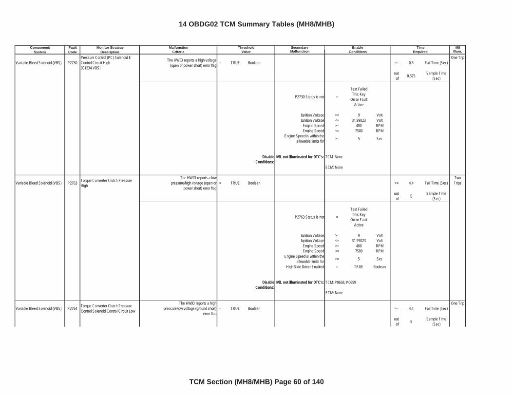
Component/ Fault Monitor Strategy Secondary MilSystem Code Description Malfunction Illum.
Malfunction Threshold Enable TimeCriteria Value Conditions Required
Variable Bleed Solenoid (VBS) P2730Pressure Control (PC) Solenoid E Control Circuit High(C1234 VBS)
The HWIO reports a high voltage (open or power short) error flag = TRUE Boolean >= 0.3 Fail Time (Sec)
One Trip
outof 0.375 Sample Time
(Sec)
P2730 Status is not =
Test Failed This Key
On or Fault Active
Ignition Voltage >= 9 VoltIgnition Voltage <= 31.99023 Volt
Engine Speed >= 400 RPMEngine Speed <= 7500 RPM
Engine Speed is within the allowable limits for >= 5 Sec
DisableConditions:
MIL not Illuminated for DTC's:
Variable Bleed Solenoid (VBS) P2763 Torque Converter Clutch Pressure High
The HWIO reports a low pressure/high voltage (open or
power short) error flag= TRUE Boolean >= 4.4 Fail Time (Sec)
TwoTrips
outof 5 Sample Time
(Sec)
P2763 Status is not =
Test Failed This Key
On or Fault Active
Ignition Voltage >= 9 VoltIgnition Voltage <= 31.99023 Volt
Engine Speed >= 400 RPMEngine Speed <= 7500 RPM
Engine Speed is within the allowable limits for >= 5 Sec
High Side Driver Enabled = TRUE Boolean
DisableConditions:
MIL not Illuminated for DTC's:
Variable Bleed Solenoid (VBS) P2764 Torque Converter Clutch Pressure Control Solenoid Control Circuit Low
The HWIO reports a high pressure/low voltage (ground short)
error flag= TRUE Boolean >= 4.4 Fail Time (Sec)
One Trip
outof 5 Sample Time
(Sec)
TCM: P0658, P0659
ECM: None
TCM: None
ECM: None
14 OBDG02 TCM Summary Tables (MH8/MHB)
TCM Section (MH8/MHB) Page 60 of 140
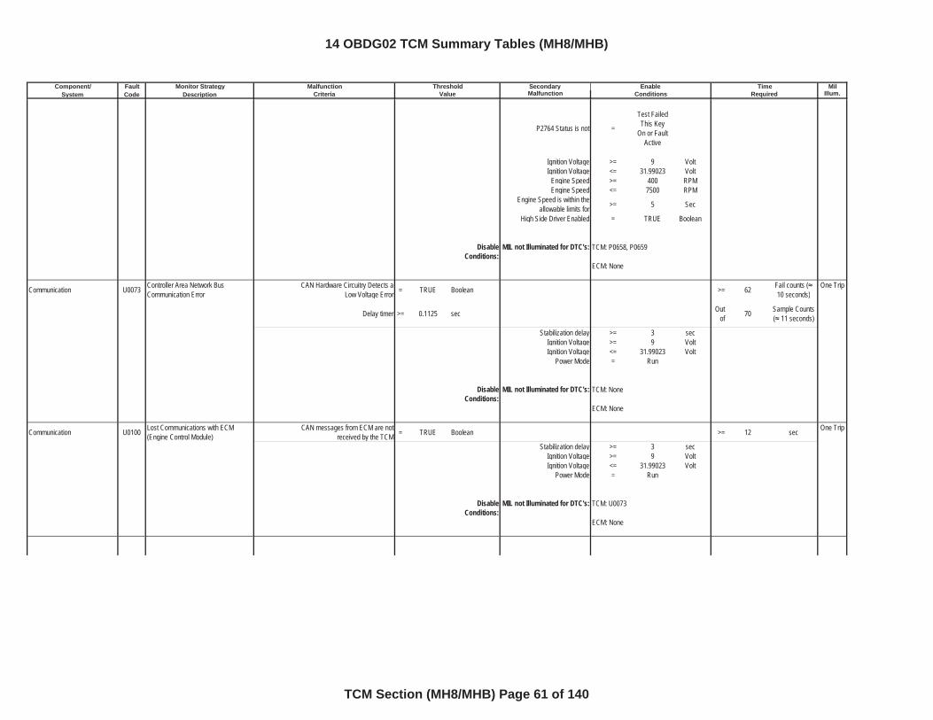
Component/ Fault Monitor Strategy Secondary MilSystem Code Description Malfunction Illum.
Malfunction Threshold Enable TimeCriteria Value Conditions Required
P2764 Status is not =
Test Failed This Key
On or Fault Active
Ignition Voltage >= 9 VoltIgnition Voltage <= 31.99023 Volt
Engine Speed >= 400 RPMEngine Speed <= 7500 RPM
Engine Speed is within the allowable limits for >= 5 Sec
High Side Driver Enabled = TRUE Boolean
DisableConditions:
MIL not Illuminated for DTC's:
Communication U0073 Controller Area Network Bus Communication Error
CAN Hardware Circuitry Detects a Low Voltage Error = TRUE Boolean >= 62 Fail counts (
10 seconds)One Trip
Delay timer >= 0.1125 sec Outof 70 Sample Counts
( 11 seconds)
Stabilization delay >= 3 secIgnition Voltage >= 9 VoltIgnition Voltage <= 31.99023 Volt
Power Mode = Run
DisableConditions:
MIL not Illuminated for DTC's:
Communication U0100 Lost Communications with ECM (Engine Control Module)
CAN messages from ECM are not received by the TCM = TRUE Boolean >= 12 sec One Trip
Stabilization delay >= 3 secIgnition Voltage >= 9 VoltIgnition Voltage <= 31.99023 Volt
Power Mode = Run
DisableConditions:
MIL not Illuminated for DTC's:
TCM: P0658, P0659
ECM: None
TCM: None
ECM: None
TCM: U0073
ECM: None
14 OBDG02 TCM Summary Tables (MH8/MHB)
TCM Section (MH8/MHB) Page 61 of 140
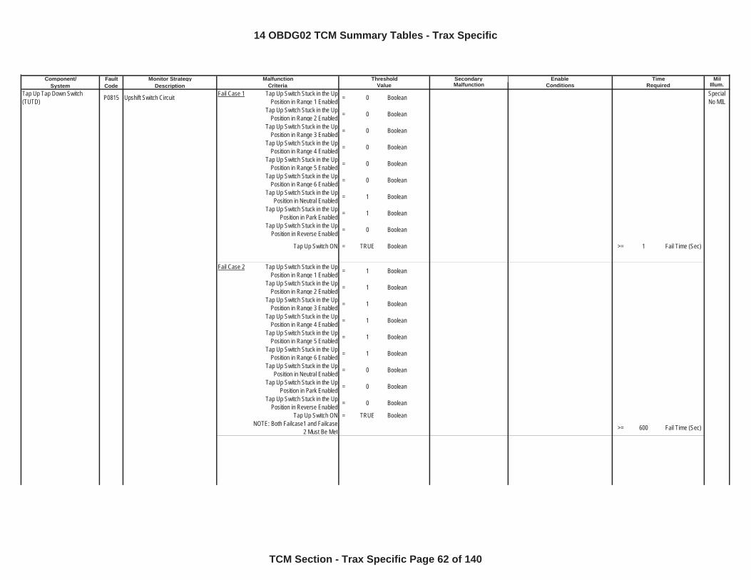
Component/ Fault Monitor Strategy Secondary MilSystem Code Description Malfunction Illum.
Tap Up Tap Down Switch (TUTD) P0815 Upshift Switch Circuit Fail Case 1 Tap Up Switch Stuck in the Up
Position in Range 1 Enabled = 0 Boolean Special No MIL
Tap Up Switch Stuck in the Up Position in Range 2 Enabled = 0 Boolean
Tap Up Switch Stuck in the Up Position in Range 3 Enabled = 0 Boolean
Tap Up Switch Stuck in the Up Position in Range 4 Enabled = 0 Boolean
Tap Up Switch Stuck in the Up Position in Range 5 Enabled = 0 Boolean
Tap Up Switch Stuck in the Up Position in Range 6 Enabled = 0 Boolean
Tap Up Switch Stuck in the Up Position in Neutral Enabled = 1 Boolean
Tap Up Switch Stuck in the Up Position in Park Enabled = 1 Boolean
Tap Up Switch Stuck in the Up Position in Reverse Enabled = 0 Boolean
Tap Up Switch ON = TRUE Boolean >= 1 Fail Time (Sec)
Fail Case 2 Tap Up Switch Stuck in the Up Position in Range 1 Enabled = 1 Boolean
Tap Up Switch Stuck in the Up Position in Range 2 Enabled = 1 Boolean
Tap Up Switch Stuck in the Up Position in Range 3 Enabled = 1 Boolean
Tap Up Switch Stuck in the Up Position in Range 4 Enabled = 1 Boolean
Tap Up Switch Stuck in the Up Position in Range 5 Enabled = 1 Boolean
Tap Up Switch Stuck in the Up Position in Range 6 Enabled = 1 Boolean
Tap Up Switch Stuck in the Up Position in Neutral Enabled = 0 Boolean
Tap Up Switch Stuck in the Up Position in Park Enabled = 0 Boolean
Tap Up Switch Stuck in the Up Position in Reverse Enabled = 0 Boolean
Tap Up Switch ON = TRUE BooleanNOTE: Both Failcase1 and Failcase
2 Must Be Met >= 600 Fail Time (Sec)
Malfunction Threshold Enable TimeCriteria Value Conditions Required
14 OBDG02 TCM Summary Tables - Trax Specific
TCM Section - Trax Specific Page 62 of 140
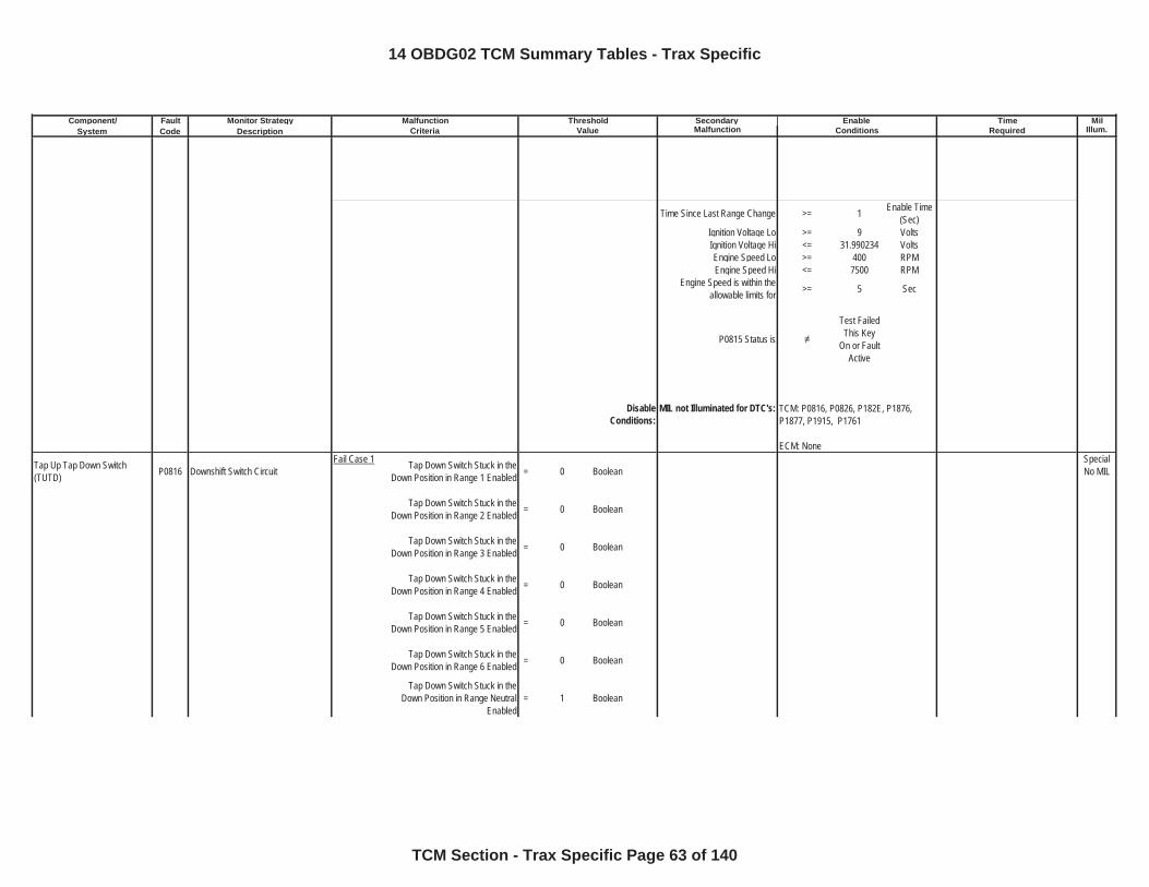
Component/ Fault Monitor Strategy Secondary MilSystem Code Description Malfunction Illum.
Malfunction Threshold Enable TimeCriteria Value Conditions Required
Time Since Last Range Change >= 1 Enable Time (Sec)
Ignition Voltage Lo >= 9 VoltsIgnition Voltage Hi <= 31.990234 VoltsEngine Speed Lo >= 400 RPMEngine Speed Hi <= 7500 RPM
Engine Speed is within the allowable limits for >= 5 Sec
P0815 Status is
Test Failed This Key
On or Fault Active
DisableConditions:
MIL not Illuminated for DTC's:
Tap Up Tap Down Switch (TUTD) P0816 Downshift Switch Circuit
Fail Case 1 Tap Down Switch Stuck in the Down Position in Range 1 Enabled = 0 Boolean
Special No MIL
Tap Down Switch Stuck in the Down Position in Range 2 Enabled = 0 Boolean
Tap Down Switch Stuck in the Down Position in Range 3 Enabled = 0 Boolean
Tap Down Switch Stuck in the Down Position in Range 4 Enabled = 0 Boolean
Tap Down Switch Stuck in the Down Position in Range 5 Enabled = 0 Boolean
Tap Down Switch Stuck in the Down Position in Range 6 Enabled = 0 Boolean
Tap Down Switch Stuck in the Down Position in Range Neutral
Enabled= 1 Boolean
TCM: P0816, P0826, P182E, P1876, P1877, P1915, P1761
ECM: None
14 OBDG02 TCM Summary Tables - Trax Specific
TCM Section - Trax Specific Page 63 of 140
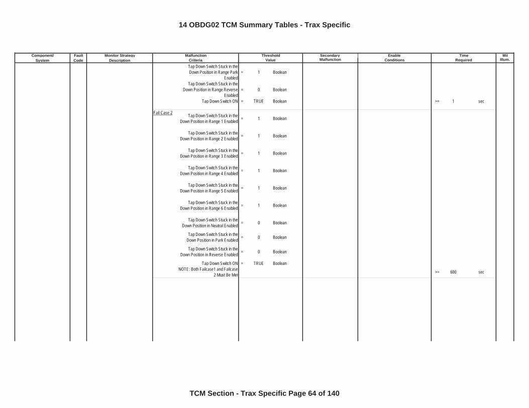
Component/ Fault Monitor Strategy Secondary MilSystem Code Description Malfunction Illum.
Malfunction Threshold Enable TimeCriteria Value Conditions RequiredTap Down Switch Stuck in the Down Position in Range Park
Enabled= 1 Boolean
Tap Down Switch Stuck in the Down Position in Range Reverse
Enabled= 0 Boolean
Tap Down Switch ON = TRUE Boolean >= 1 sec
Fail Case 2 Tap Down Switch Stuck in the Down Position in Range 1 Enabled = 1 Boolean
Tap Down Switch Stuck in the Down Position in Range 2 Enabled = 1 Boolean
Tap Down Switch Stuck in the Down Position in Range 3 Enabled = 1 Boolean
Tap Down Switch Stuck in the Down Position in Range 4 Enabled = 1 Boolean
Tap Down Switch Stuck in the Down Position in Range 5 Enabled = 1 Boolean
Tap Down Switch Stuck in the Down Position in Range 6 Enabled = 1 Boolean
Tap Down Switch Stuck in the Down Position in Neutral Enabled = 0 Boolean
Tap Down Switch Stuck in the Down Position in Park Enabled = 0 Boolean
Tap Down Switch Stuck in the Down Position in Reverse Enabled = 0 Boolean
Tap Down Switch ON = TRUE BooleanNOTE: Both Failcase1 and Failcase
2 Must Be Met >= 600 sec
14 OBDG02 TCM Summary Tables - Trax Specific
TCM Section - Trax Specific Page 64 of 140
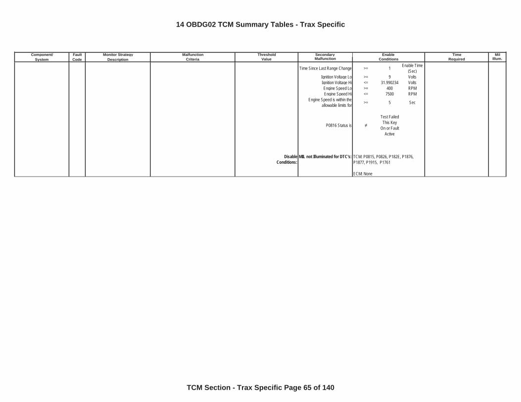
Component/ Fault Monitor Strategy Secondary MilSystem Code Description Malfunction Illum.
Malfunction Threshold Enable TimeCriteria Value Conditions Required
Time Since Last Range Change >= 1 Enable Time (Sec)
Ignition Voltage Lo >= 9 VoltsIgnition Voltage Hi <= 31.990234 VoltsEngine Speed Lo >= 400 RPMEngine Speed Hi <= 7500 RPM
Engine Speed is within the allowable limits for >= 5 Sec
P0816 Status is
Test Failed This Key
On or Fault Active
DisableConditions:
MIL not Illuminated for DTC's: TCM: P0815, P0826, P182E, P1876, P1877, P1915, P1761
ECM: None
14 OBDG02 TCM Summary Tables - Trax Specific
TCM Section - Trax Specific Page 65 of 140
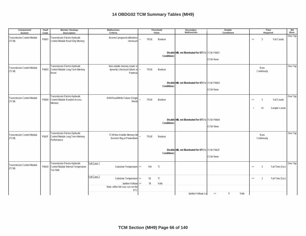
Component/ Fault Monitor Strategy Secondary MilSystem Code Description Malfunction Illum.
Transmission Control Module (TCM) P0601 Transmission Electro-Hydraulic
Control Module Read Only MemoryIncorrect program/calibrations
checksum = TRUE Boolean >= 5 Fail CountsOne Trip
DisableConditions:
MIL not Illuminated for DTC's:
Transmission Control Module (TCM) P0603
Transmission Electro-Hydraulic Control Module Long-Term Memory Reset
Non-volatile memory (static or dynamic) checksum failure at
Powerup= TRUE Boolean Runs
Continously
One Trip
DisableConditions:
MIL not Illuminated for DTC's:
Transmission Control Module (TCM) P0604
Transmission Electro-Hydraulic Control Module Random Access Memory
RAM Read/Write Failure (Single Word) = TRUE Boolean >= 5 Fail Counts
One Trip
= 16 Sample Counts
DisableConditions:
MIL not Illuminated for DTC's:
Transmission Control Module (TCM) P062F
Transmission Electro-Hydraulic Control Module Long Term Memory Performance
TCM Non-Volatile Memory bit Incorrect flag at Powerdown = TRUE Boolean Runs
Continously
One Trip
DisableConditions:
MIL not Illuminated for DTC's:
Transmission Control Module (TCM) P0634
Transmission Electro-Hydraulic Control Module Internal Temperature Too High
Fail Case 1Substrate Temperature >= 144 ºC >= 5 Fail Time (Sec)
One Trip
Fail Case 2 Substrate Temperature >= 50 ºC >= 2 Fail Time (Sec)
Ignition Voltage >= 18 VoltsNote: either fail case can set the
DTCIgnition Voltage Lo >= 9 Volts
Malfunction Threshold Enable TimeCriteria Value Conditions Required
TCM: P0601
ECM: None
TCM: P0603
ECM: None
TCM: P0604
ECM: None
TCM: P062F
ECM: None
14 OBDG02 TCM Summary Tables (MH9)
TCM Section (MH9) Page 66 of 140
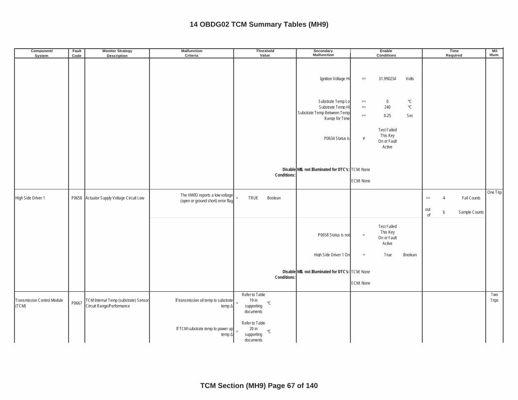
Component/ Fault Monitor Strategy Secondary MilSystem Code Description Malfunction Illum.
Malfunction Threshold Enable TimeCriteria Value Conditions Required
Ignition Voltage Hi <= 31.990234 Volts
Substrate Temp Lo >= 0 ºCSubstrate Temp Hi <= 240 ºC
Substrate Temp Between Temp Range for Time >= 0.25 Sec
P0634 Status is
Test Failed This Key
On or Fault Active
DisableConditions:
MIL not Illuminated for DTC's:
High Side Driver 1 P0658 Actuator Supply Voltage Circuit Low The HWIO reports a low voltage (open or ground short) error flag = TRUE Boolean >= 4 Fail Counts
One Trip
outof 6 Sample Counts
P0658 Status is not =
Test Failed This Key
On or Fault Active
High Side Driver 1 On = True Boolean
DisableConditions:
MIL not Illuminated for DTC's:
Transmission Control Module (TCM) P0667 TCM Internal Temp (substrate) Sensor
Circuit Range/PerformanceIf transmission oil temp to substrate
temp >
Refer to Table 19 in
supportingdocuments
ºC
TwoTrips
If TCM substrate temp to power up temp >
Refer to Table 20 in
supportingdocuments
ºC
TCM: None
ECM: None
TCM: None
ECM: None
14 OBDG02 TCM Summary Tables (MH9)
TCM Section (MH9) Page 67 of 140
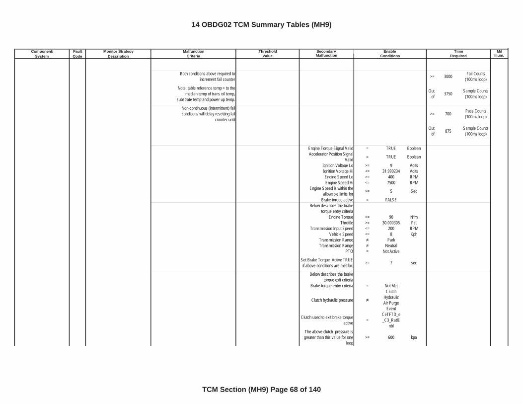
Component/ Fault Monitor Strategy Secondary MilSystem Code Description Malfunction Illum.
Malfunction Threshold Enable TimeCriteria Value Conditions Required
Both conditions above required to increment fail counter >= 3000 Fail Counts
(100ms loop)
Note: table reference temp = to the median temp of trans oil temp,
substrate temp and power up temp.
Outof 3750 Sample Counts
(100ms loop)
Non-continuous (intermittent) fail conditions will delay resetting fail
counter until>= 700 Pass Counts
(100ms loop)
Outof 875 Sample Counts
(100ms loop)
Engine Torque Signal Valid = TRUE BooleanAccelerator Position Signal
Valid = TRUE Boolean
Ignition Voltage Lo >= 9 VoltsIgnition Voltage Hi <= 31.990234 VoltsEngine Speed Lo >= 400 RPMEngine Speed Hi <= 7500 RPM
Engine Speed is within the allowable limits for >= 5 Sec
Brake torque active = FALSEBelow describes the brake
torque entry criteriaEngine Torque >= 90 N*m
Throttle >= 30.000305 PctTransmission Input Speed <= 200 RPM
Vehicle Speed <= 8 KphTransmission Range ParkTransmission Range Neutral
PTO = Not Active
Set Brake Torque Active TRUE if above conditions are met for: >= 7 sec
Below describes the brake torque exit criteria
Brake torque entry criteria = Not Met
Clutch hydraulic pressure
ClutchHydraulic Air Purge
Event
Clutch used to exit brake torque active =
CeTFTD_e_C3_RatlE
nblThe above clutch pressure is greater than this value for one
loop>= 600 kpa
14 OBDG02 TCM Summary Tables (MH9)
TCM Section (MH9) Page 68 of 140
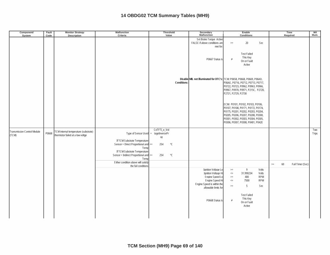
Component/ Fault Monitor Strategy Secondary MilSystem Code Description Malfunction Illum.
Malfunction Threshold Enable TimeCriteria Value Conditions Required
Set Brake Torque Active FALSE if above conditions are
met for:>= 20 Sec
P0667 Status is
Test Failed This Key
On or Fault Active
DisableConditions:
MIL not Illuminated for DTC's:
Transmission Control Module (TCM) P0668 TCM internal temperature (substrate)
thermistor failed at a low voltge Type of Sensor Used =CeTFTI_e_VoltageInversePr
op
TwoTrips
If TCM Substrate Temperature Sensor = Direct Proportional and
Temp<= 254 ºC
If TCM Substrate Temperature Sensor = Indirect Proportional and
Temp>= 254 ºC
Either condition above will satisfy the fail conditions >= 60 Fail Timer (Sec)
Ignition Voltage Lo >= 9 VoltsIgnition Voltage Hi <= 31.990234 VoltsEngine Speed Lo >= 400 RPMEngine Speed Hi <= 7500 RPM
Engine Speed is within the allowable limits for >= 5 Sec
P0668 Status is
Test Failed This Key
On or Fault Active
TCM: P0658, P0668, P0669, P06AD, P06AE, P0716, P0712, P0713, P0717, P0722, P0723, P0962, P0963, P0966, P0967, P0970, P0971, P215C, P2720, P2721, P2729, P2730
ECM: P0101, P0102, P0103, P0106, P0107, P0108, P0171, P0172, P0174, P0175, P0201, P0202, P0203, P0204, P0205, P0206, P0207, P0208, P0300, P0301, P0302, P0303, P0304, P0305, P0306, P0307, P0308, P0401, P042E
14 OBDG02 TCM Summary Tables (MH9)
TCM Section (MH9) Page 69 of 140
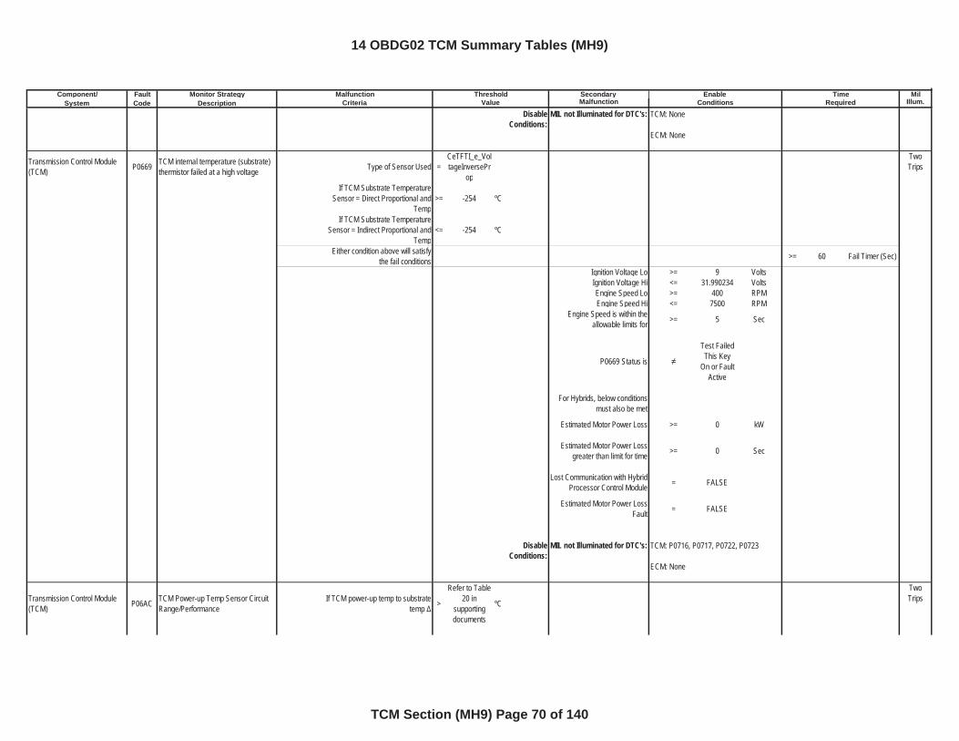
Component/ Fault Monitor Strategy Secondary MilSystem Code Description Malfunction Illum.
Malfunction Threshold Enable TimeCriteria Value Conditions Required
DisableConditions:
MIL not Illuminated for DTC's:
Transmission Control Module (TCM) P0669 TCM internal temperature (substrate)
thermistor failed at a high voltage Type of Sensor Used =CeTFTI_e_VoltageInversePr
op
TwoTrips
If TCM Substrate Temperature Sensor = Direct Proportional and
Temp>= -254 ºC
If TCM Substrate Temperature Sensor = Indirect Proportional and
Temp<= -254 ºC
Either condition above will satisfy the fail conditions >= 60 Fail Timer (Sec)
Ignition Voltage Lo >= 9 VoltsIgnition Voltage Hi <= 31.990234 VoltsEngine Speed Lo >= 400 RPMEngine Speed Hi <= 7500 RPM
Engine Speed is within the allowable limits for >= 5 Sec
P0669 Status is
Test Failed This Key
On or Fault Active
For Hybrids, below conditions must also be met
Estimated Motor Power Loss >= 0 kW
Estimated Motor Power Loss greater than limit for time >= 0 Sec
Lost Communication with Hybrid Processor Control Module = FALSE
Estimated Motor Power Loss Fault = FALSE
DisableConditions:
MIL not Illuminated for DTC's:
Transmission Control Module (TCM) P06AC TCM Power-up Temp Sensor Circuit
Range/PerformanceIf TCM power-up temp to substrate
temp >
Refer to Table 20 in
supportingdocuments
ºC
TwoTrips
TCM: None
ECM: None
TCM: P0716, P0717, P0722, P0723
ECM: None
14 OBDG02 TCM Summary Tables (MH9)
TCM Section (MH9) Page 70 of 140
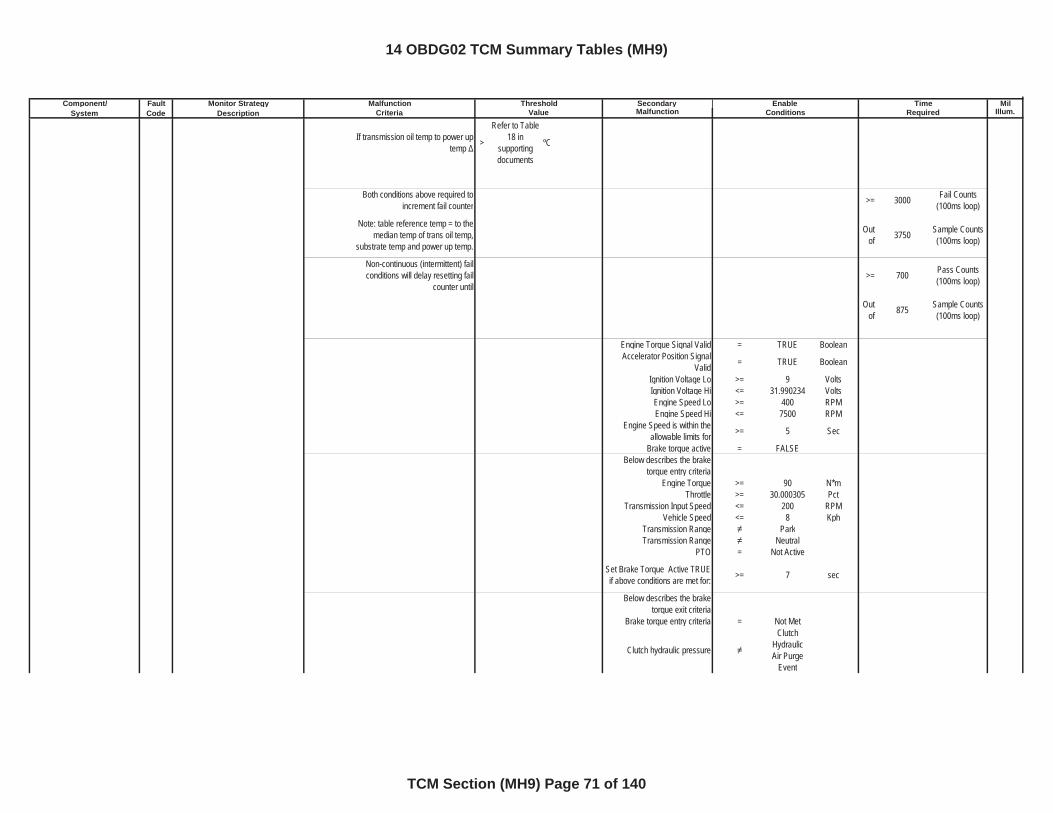
Component/ Fault Monitor Strategy Secondary MilSystem Code Description Malfunction Illum.
Malfunction Threshold Enable TimeCriteria Value Conditions Required
If transmission oil temp to power up temp >
Refer to Table 18 in
supportingdocuments
ºC
Both conditions above required to increment fail counter >= 3000 Fail Counts
(100ms loop)
Note: table reference temp = to the median temp of trans oil temp,
substrate temp and power up temp.
Outof 3750 Sample Counts
(100ms loop)
Non-continuous (intermittent) fail conditions will delay resetting fail
counter until>= 700 Pass Counts
(100ms loop)
Outof 875 Sample Counts
(100ms loop)
Engine Torque Signal Valid = TRUE BooleanAccelerator Position Signal
Valid = TRUE Boolean
Ignition Voltage Lo >= 9 VoltsIgnition Voltage Hi <= 31.990234 VoltsEngine Speed Lo >= 400 RPMEngine Speed Hi <= 7500 RPM
Engine Speed is within the allowable limits for >= 5 Sec
Brake torque active = FALSEBelow describes the brake
torque entry criteriaEngine Torque >= 90 N*m
Throttle >= 30.000305 PctTransmission Input Speed <= 200 RPM
Vehicle Speed <= 8 KphTransmission Range ParkTransmission Range Neutral
PTO = Not Active
Set Brake Torque Active TRUE if above conditions are met for: >= 7 sec
Below describes the brake torque exit criteria
Brake torque entry criteria = Not Met
Clutch hydraulic pressure
ClutchHydraulic Air Purge
Event
14 OBDG02 TCM Summary Tables (MH9)
TCM Section (MH9) Page 71 of 140
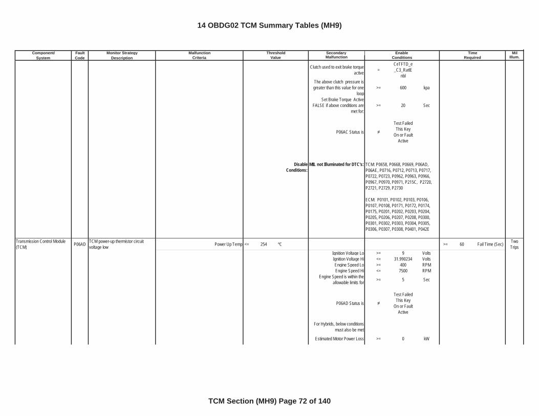
Component/ Fault Monitor Strategy Secondary MilSystem Code Description Malfunction Illum.
Malfunction Threshold Enable TimeCriteria Value Conditions Required
Clutch used to exit brake torque active =
CeTFTD_e_C3_RatlE
nblThe above clutch pressure is greater than this value for one
loop>= 600 kpa
Set Brake Torque Active FALSE if above conditions are
met for:>= 20 Sec
P06AC Status is
Test Failed This Key
On or Fault Active
DisableConditions:
MIL not Illuminated for DTC's:
Transmission Control Module (TCM) P06AD TCM power-up thermistor circuit
voltage low Power Up Temp <= 254 ºC >= 60 Fail Time (Sec) TwoTrips
Ignition Voltage Lo >= 9 VoltsIgnition Voltage Hi <= 31.990234 VoltsEngine Speed Lo >= 400 RPMEngine Speed Hi <= 7500 RPM
Engine Speed is within the allowable limits for >= 5 Sec
P06AD Status is
Test Failed This Key
On or Fault Active
For Hybrids, below conditions must also be met
Estimated Motor Power Loss >= 0 kW
TCM: P0658, P0668, P0669, P06AD, P06AE, P0716, P0712, P0713, P0717, P0722, P0723, P0962, P0963, P0966, P0967, P0970, P0971, P215C, P2720, P2721, P2729, P2730
ECM: P0101, P0102, P0103, P0106, P0107, P0108, P0171, P0172, P0174, P0175, P0201, P0202, P0203, P0204, P0205, P0206, P0207, P0208, P0300, P0301, P0302, P0303, P0304, P0305, P0306, P0307, P0308, P0401, P042E
14 OBDG02 TCM Summary Tables (MH9)
TCM Section (MH9) Page 72 of 140
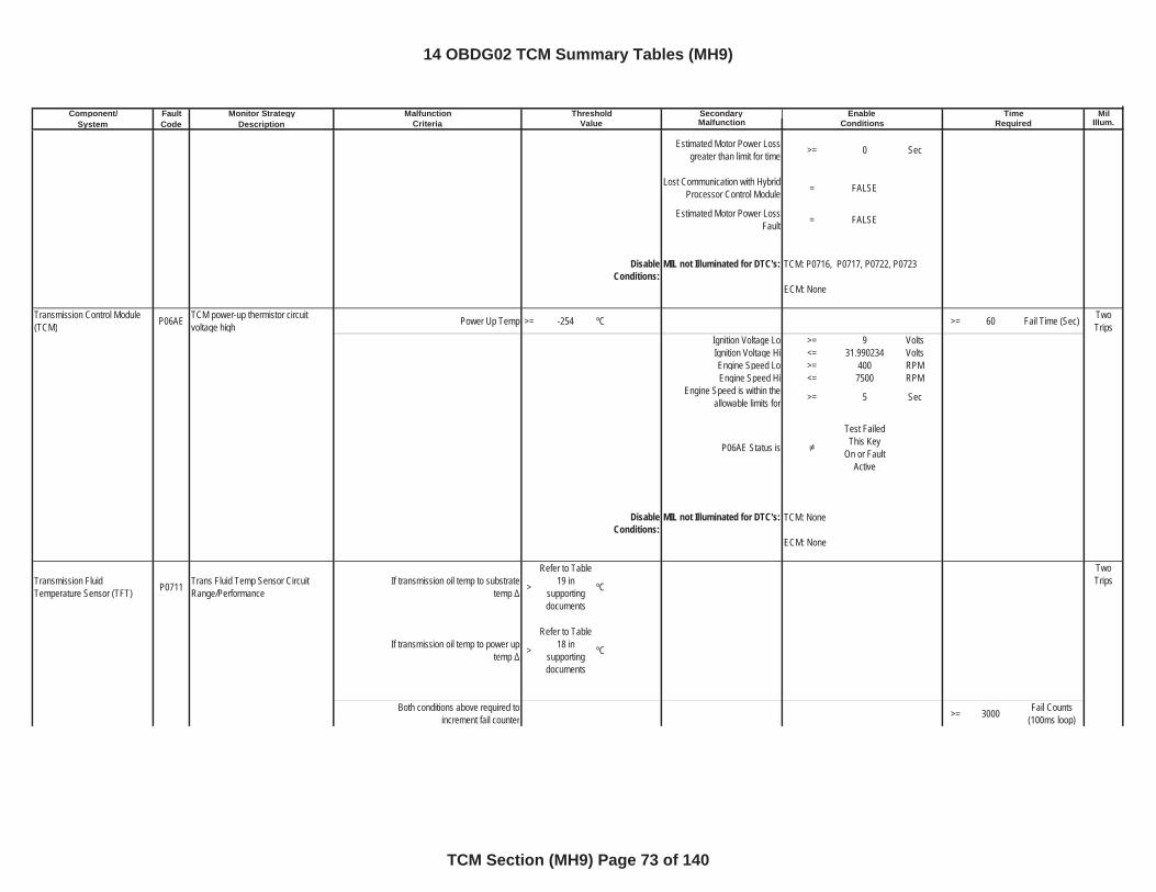
Component/ Fault Monitor Strategy Secondary MilSystem Code Description Malfunction Illum.
Malfunction Threshold Enable TimeCriteria Value Conditions Required
Estimated Motor Power Loss greater than limit for time >= 0 Sec
Lost Communication with Hybrid Processor Control Module = FALSE
Estimated Motor Power Loss Fault = FALSE
DisableConditions:
MIL not Illuminated for DTC's:
Transmission Control Module (TCM) P06AE TCM power-up thermistor circuit
voltage high Power Up Temp >= -254 ºC >= 60 Fail Time (Sec) TwoTrips
Ignition Voltage Lo >= 9 VoltsIgnition Voltage Hi <= 31.990234 VoltsEngine Speed Lo >= 400 RPMEngine Speed Hi <= 7500 RPM
Engine Speed is within the allowable limits for >= 5 Sec
P06AE Status is
Test Failed This Key
On or Fault Active
DisableConditions:
MIL not Illuminated for DTC's:
Transmission Fluid Temperature Sensor (TFT) P0711 Trans Fluid Temp Sensor Circuit
Range/PerformanceIf transmission oil temp to substrate
temp >
Refer to Table 19 in
supportingdocuments
ºC
TwoTrips
If transmission oil temp to power up temp >
Refer to Table 18 in
supportingdocuments
ºC
Both conditions above required to increment fail counter >= 3000 Fail Counts
(100ms loop)
TCM: P0716, P0717, P0722, P0723
ECM: None
TCM: None
ECM: None
14 OBDG02 TCM Summary Tables (MH9)
TCM Section (MH9) Page 73 of 140
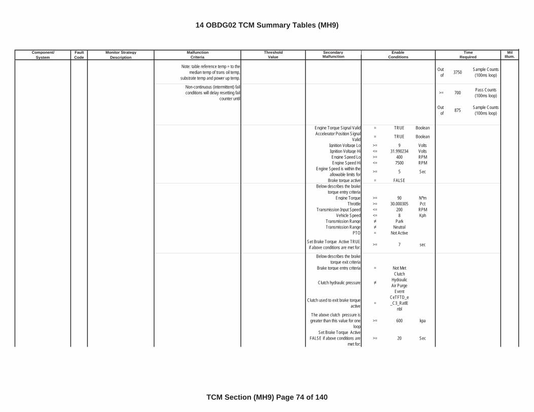
Component/ Fault Monitor Strategy Secondary MilSystem Code Description Malfunction Illum.
Malfunction Threshold Enable TimeCriteria Value Conditions Required
Note: table reference temp = to the median temp of trans oil temp,
substrate temp and power up temp.
Outof 3750 Sample Counts
(100ms loop)
Non-continuous (intermittent) fail conditions will delay resetting fail
counter until>= 700 Pass Counts
(100ms loop)
Outof 875 Sample Counts
(100ms loop)
Engine Torque Signal Valid = TRUE BooleanAccelerator Position Signal
Valid = TRUE Boolean
Ignition Voltage Lo >= 9 VoltsIgnition Voltage Hi <= 31.990234 VoltsEngine Speed Lo >= 400 RPMEngine Speed Hi <= 7500 RPM
Engine Speed is within the allowable limits for >= 5 Sec
Brake torque active = FALSEBelow describes the brake
torque entry criteriaEngine Torque >= 90 N*m
Throttle >= 30.000305 PctTransmission Input Speed <= 200 RPM
Vehicle Speed <= 8 KphTransmission Range ParkTransmission Range Neutral
PTO = Not Active
Set Brake Torque Active TRUE if above conditions are met for: >= 7 sec
Below describes the brake torque exit criteria
Brake torque entry criteria = Not Met
Clutch hydraulic pressure
ClutchHydraulic Air Purge
Event
Clutch used to exit brake torque active =
CeTFTD_e_C3_RatlE
nblThe above clutch pressure is greater than this value for one
loop>= 600 kpa
Set Brake Torque Active FALSE if above conditions are
met for:>= 20 Sec
14 OBDG02 TCM Summary Tables (MH9)
TCM Section (MH9) Page 74 of 140
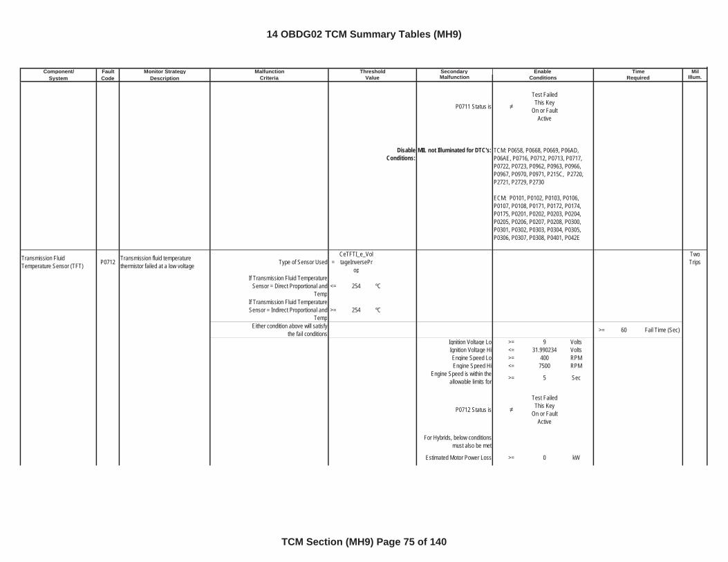
Component/ Fault Monitor Strategy Secondary MilSystem Code Description Malfunction Illum.
Malfunction Threshold Enable TimeCriteria Value Conditions Required
P0711 Status is
Test Failed This Key
On or Fault Active
DisableConditions:
MIL not Illuminated for DTC's:
Transmission Fluid Temperature Sensor (TFT) P0712 Transmission fluid temperature
thermistor failed at a low voltage Type of Sensor Used =CeTFTI_e_VoltageInversePr
op
TwoTrips
If Transmission Fluid Temperature Sensor = Direct Proportional and
Temp<= 254 ºC
If Transmission Fluid Temperature Sensor = Indirect Proportional and
Temp>= 254 ºC
Either condition above will satisfy the fail conditions >= 60 Fail Time (Sec)
Ignition Voltage Lo >= 9 VoltsIgnition Voltage Hi <= 31.990234 VoltsEngine Speed Lo >= 400 RPMEngine Speed Hi <= 7500 RPM
Engine Speed is within the allowable limits for >= 5 Sec
P0712 Status is
Test Failed This Key
On or Fault Active
For Hybrids, below conditions must also be met
Estimated Motor Power Loss >= 0 kW
TCM: P0658, P0668, P0669, P06AD, P06AE, P0716, P0712, P0713, P0717, P0722, P0723, P0962, P0963, P0966, P0967, P0970, P0971, P215C, P2720, P2721, P2729, P2730
ECM: P0101, P0102, P0103, P0106, P0107, P0108, P0171, P0172, P0174, P0175, P0201, P0202, P0203, P0204, P0205, P0206, P0207, P0208, P0300, P0301, P0302, P0303, P0304, P0305, P0306, P0307, P0308, P0401, P042E
14 OBDG02 TCM Summary Tables (MH9)
TCM Section (MH9) Page 75 of 140
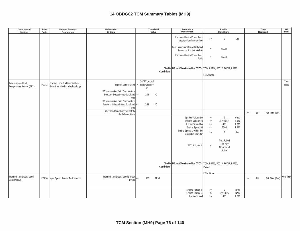
Component/ Fault Monitor Strategy Secondary MilSystem Code Description Malfunction Illum.
Malfunction Threshold Enable TimeCriteria Value Conditions Required
Estimated Motor Power Loss greater than limit for time >= 0 Sec
Lost Communication with Hybrid Processor Control Module = FALSE
Estimated Motor Power Loss Fault = FALSE
DisableConditions:
MIL not Illuminated for DTC's:
Transmission Fluid Temperature Sensor (TFT) P0713 Transmission fluid temperature
thermistor failed at a high voltage Type of Sensor Used =CeTFTI_e_VoltageInversePr
op
TwoTrips
If Transmission Fluid Temperature Sensor = Direct Proportional and
Temp>= -254 ºC
If Transmission Fluid Temperature Sensor = Indirect Proportional and
Temp<= -254 ºC
Either condition above will satisfy the fail conditions >= 60 Fail Time (Sec)
Ignition Voltage Lo >= 9 VoltsIgnition Voltage Hi <= 31.990234 VoltsEngine Speed Lo >= 400 RPMEngine Speed Hi <= 7500 RPM
Engine Speed is within the allowable limits for >= 5 Sec
P0713 Status is
Test Failed This Key
On or Fault Active
DisableConditions:
MIL not Illuminated for DTC's:
Transmission Input Speed Sensor (TISS) P0716 Input Speed Sensor Performance Transmission Input Speed Sensor
Drops >= 1350 RPM >= 0.8 Fail Time (Sec) One Trip
Engine Torque is >= 0 N*mEngine Torque is <= 8191.875 N*m
Engine Speed >= 400 RPM
TCM: P0716, P0717, P0722, P0723
ECM: None
TCM: P0713, P0716, P0717, P0722, P0723
ECM: None
14 OBDG02 TCM Summary Tables (MH9)
TCM Section (MH9) Page 76 of 140
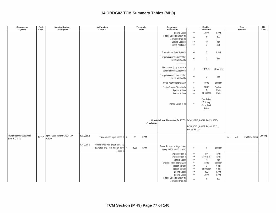
Component/ Fault Monitor Strategy Secondary MilSystem Code Description Malfunction Illum.
Malfunction Threshold Enable TimeCriteria Value Conditions Required
Engine Speed <= 7500 RPMEngine Speed is within the
allowable limits for >= 5 Sec
Vehicle Speed is >= 10 KphThrottle Position is >= 0 Pct
--------------
Transmission Input Speed is >= 0 RPM
The previous requirement has been satisfied for >= 0 Sec
--------------
The change (loop to loop) in transmission input speed is < 8191.75 RPM/Loop
The previous requirement has been satisfied for >= 0 Sec
Throttle Position Signal Valid = TRUE Boolean
Engine Torque Signal Valid = TRUE BooleanIgnition Voltage >= 9 VoltsIgnition Voltage <= 31.990234 Volts
P0716 Status is not =
Test Failed This Key
On or Fault Active
DisableConditions:
MIL not Illuminated for DTC's:
Transmission Input Speed Sensor (TISS) P0717 Input Speed Sensor Circuit Low
VoltageFail Case 1 Transmission Input Speed is < 33 RPM >= 4.5 Fail Time (Sec) One Trip
Fail Case 2 When P0722 DTC Status equal to Test Failed and Transmission Input
Speed is< 1000 RPM Controller uses a single power
supply for the speed sensors = 1 Boolean
Engine Torque is >= 50 N*mEngine Torque is <= 8191.875 N*m
Vehicle Speed >= 16 KphEngine Torque Signal Valid = TRUE Boolean
Ignition Voltage >= 9 VoltsIgnition Voltage <= 31.990234 Volts
Engine Speed >= 400 RPMEngine Speed <= 7500 RPM
Engine Speed is within the allowable limits for >= 5 Sec
TCM: P0717, P0752, P0973, P0974
ECM: P0101, P0102, P0103, P0121, P0122, P0123
14 OBDG02 TCM Summary Tables (MH9)
TCM Section (MH9) Page 77 of 140
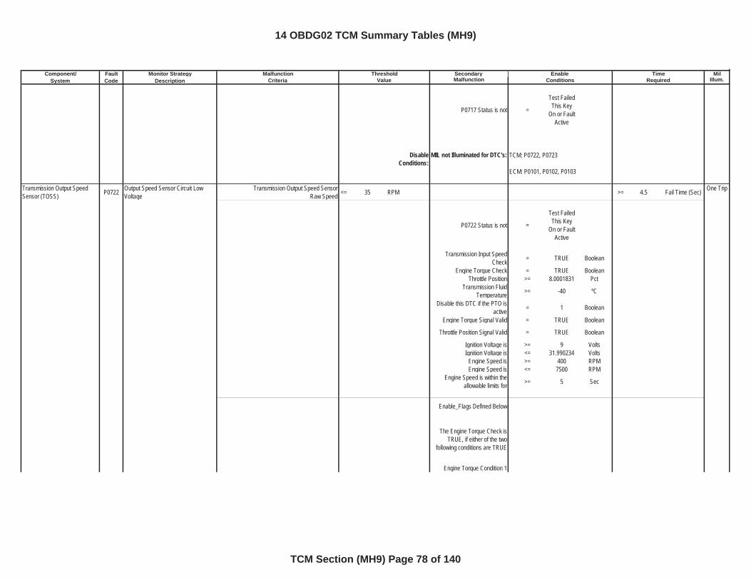
Component/ Fault Monitor Strategy Secondary MilSystem Code Description Malfunction Illum.
Malfunction Threshold Enable TimeCriteria Value Conditions Required
P0717 Status is not =
Test Failed This Key
On or Fault Active
DisableConditions:
MIL not Illuminated for DTC's:
Transmission Output Speed Sensor (TOSS) P0722 Output Speed Sensor Circuit Low
VoltageTransmission Output Speed Sensor
Raw Speed <= 35 RPM >= 4.5 Fail Time (Sec) One Trip
P0722 Status is not =
Test Failed This Key
On or Fault Active
Transmission Input Speed Check = TRUE Boolean
Engine Torque Check = TRUE BooleanThrottle Position >= 8.0001831 Pct
Transmission Fluid Temperature >= -40 ºC
Disable this DTC if the PTO is active = 1 Boolean
Engine Torque Signal Valid = TRUE Boolean
Throttle Position Signal Valid = TRUE Boolean
Ignition Voltage is >= 9 VoltsIgnition Voltage is <= 31.990234 Volts
Engine Speed is >= 400 RPMEngine Speed is <= 7500 RPM
Engine Speed is within the allowable limits for >= 5 Sec
Enable_Flags Defined Below
The Engine Torque Check is TRUE, if either of the two
following conditions are TRUE
Engine Torque Condition 1
TCM: P0722, P0723
ECM: P0101, P0102, P0103
14 OBDG02 TCM Summary Tables (MH9)
TCM Section (MH9) Page 78 of 140
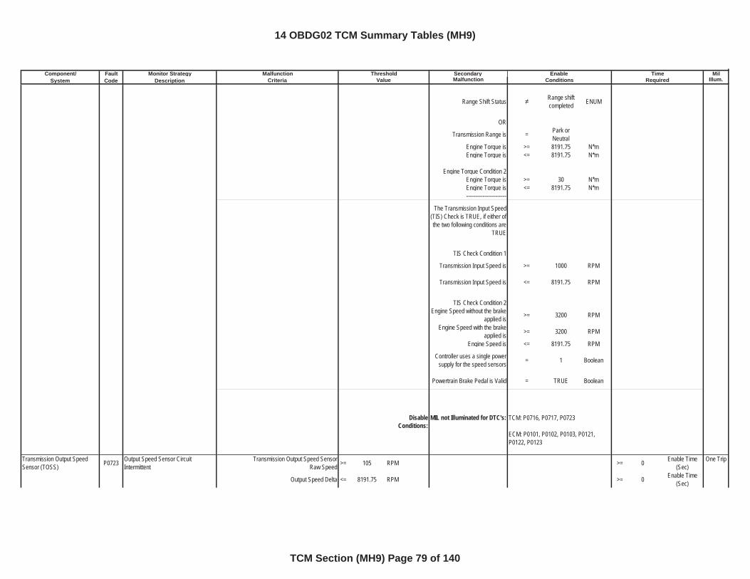
Component/ Fault Monitor Strategy Secondary MilSystem Code Description Malfunction Illum.
Malfunction Threshold Enable TimeCriteria Value Conditions Required
Range Shift Status Range shift completed ENUM
OR
Transmission Range is = Park or Neutral
Engine Torque is >= 8191.75 N*mEngine Torque is <= 8191.75 N*m
Engine Torque Condition 2Engine Torque is >= 30 N*mEngine Torque is <= 8191.75 N*m----------------------
The Transmission Input Speed (TIS) Check is TRUE, if either of the two following conditions are
TRUE
TIS Check Condition 1
Transmission Input Speed is >= 1000 RPM
Transmission Input Speed is <= 8191.75 RPM
TIS Check Condition 2Engine Speed without the brake
applied is >= 3200 RPM
Engine Speed with the brake applied is >= 3200 RPM
Engine Speed is <= 8191.75 RPM
Controller uses a single power supply for the speed sensors = 1 Boolean
Powertrain Brake Pedal is Valid = TRUE Boolean
DisableConditions:
MIL not Illuminated for DTC's:
Transmission Output Speed Sensor (TOSS) P0723 Output Speed Sensor Circuit
IntermittentTransmission Output Speed Sensor
Raw Speed >= 105 RPM >= 0 Enable Time (Sec)
One Trip
Output Speed Delta <= 8191.75 RPM >= 0 Enable Time (Sec)
TCM: P0716, P0717, P0723
ECM: P0101, P0102, P0103, P0121, P0122, P0123
14 OBDG02 TCM Summary Tables (MH9)
TCM Section (MH9) Page 79 of 140
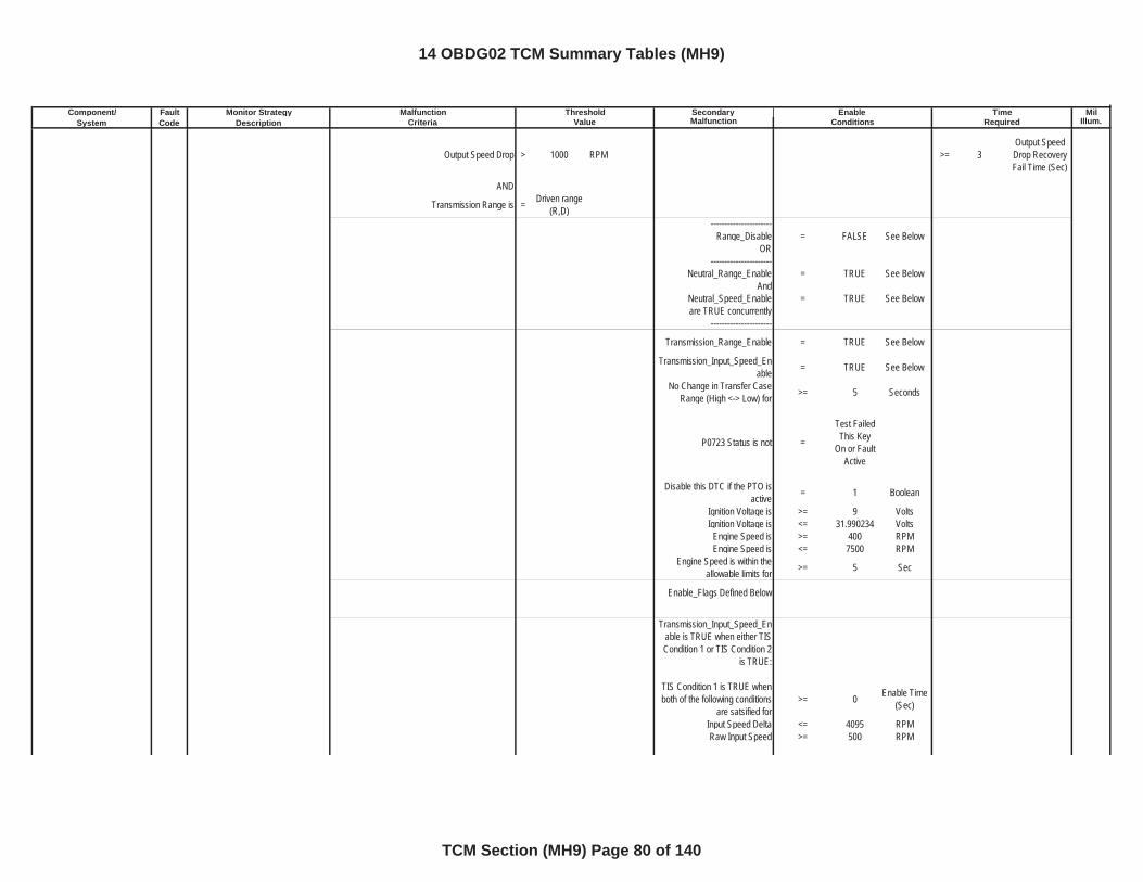
Component/ Fault Monitor Strategy Secondary MilSystem Code Description Malfunction Illum.
Malfunction Threshold Enable TimeCriteria Value Conditions Required
Output Speed Drop > 1000 RPM >= 3Output Speed Drop Recovery Fail Time (Sec)
AND
Transmission Range is = Driven range (R,D)
----------------------Range_Disable = FALSE See Below
OR----------------------
Neutral_Range_Enable = TRUE See BelowAnd
Neutral_Speed_Enable = TRUE See Beloware TRUE concurrently
----------------------
Transmission_Range_Enable = TRUE See Below
Transmission_Input_Speed_Enable = TRUE See Below
No Change in Transfer Case Range (High <-> Low) for >= 5 Seconds
P0723 Status is not =
Test Failed This Key
On or Fault Active
Disable this DTC if the PTO is active = 1 Boolean
Ignition Voltage is >= 9 VoltsIgnition Voltage is <= 31.990234 Volts
Engine Speed is >= 400 RPMEngine Speed is <= 7500 RPM
Engine Speed is within the allowable limits for >= 5 Sec
Enable_Flags Defined Below
Transmission_Input_Speed_Enable is TRUE when either TIS Condition 1 or TIS Condition 2
is TRUE:
TIS Condition 1 is TRUE when both of the following conditions
are satsified for >= 0 Enable Time
(Sec)
Input Speed Delta <= 4095 RPMRaw Input Speed >= 500 RPM
14 OBDG02 TCM Summary Tables (MH9)
TCM Section (MH9) Page 80 of 140
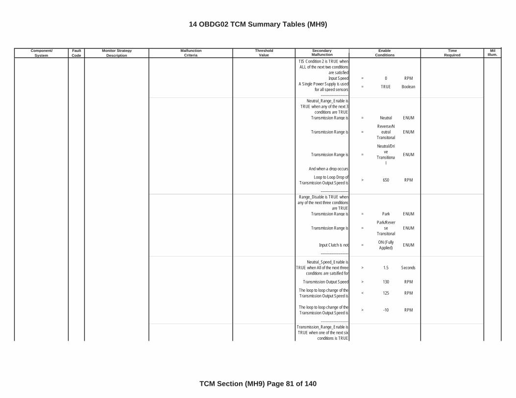
Component/ Fault Monitor Strategy Secondary MilSystem Code Description Malfunction Illum.
Malfunction Threshold Enable TimeCriteria Value Conditions Required
TIS Condition 2 is TRUE when ALL of the next two conditions
are satisfiedInput Speed = 0 RPM
A Single Power Supply is used for all speed sensors = TRUE Boolean
----------------------Neutral_Range_Enable is
TRUE when any of the next 3 conditions are TRUE
Transmission Range is = Neutral ENUM
Transmission Range is =Reverse/N
eutralTransitonal
ENUM
Transmission Range is =
Neutral/Drive
Transitional
ENUM
And when a drop occurs
Loop to Loop Drop of Transmission Output Speed is > 650 RPM
----------------------Range_Disable is TRUE when
any of the next three conditions are TRUE
Transmission Range is = Park ENUM
Transmission Range is =Park/Rever
seTransitonal
ENUM
Input Clutch is not = ON (Fully Applied) ENUM
----------------------
Neutral_Speed_Enable is TRUE when All of the next three
conditions are satsified for > 1.5 Seconds
Transmission Output Speed > 130 RPM
The loop to loop change of the Transmission Output Speed is < 125 RPM
The loop to loop change of the Transmission Output Speed is > -10 RPM
----------------------Transmission_Range_Enable is TRUE when one of the next six
conditions is TRUE
14 OBDG02 TCM Summary Tables (MH9)
TCM Section (MH9) Page 81 of 140
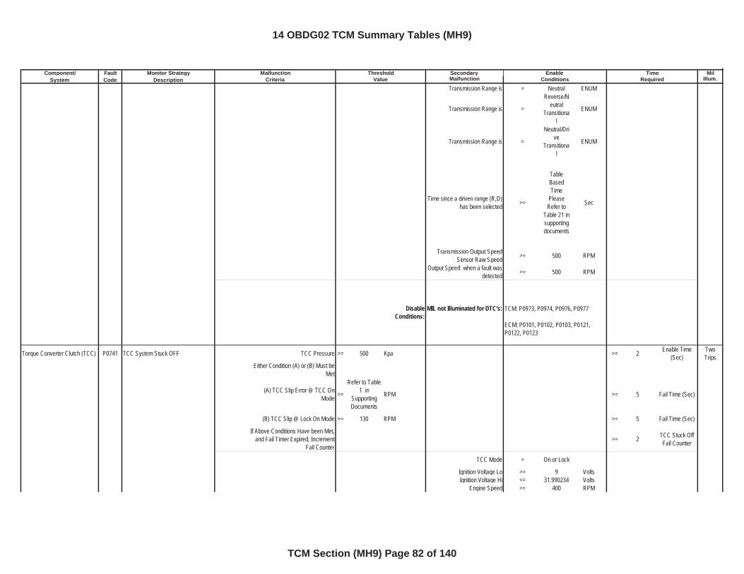
Component/ Fault Monitor Strategy Secondary MilSystem Code Description Malfunction Illum.
Malfunction Threshold Enable TimeCriteria Value Conditions Required
Transmission Range is = Neutral ENUM
Transmission Range is =
Reverse/Neutral
Transitional
ENUM
Transmission Range is =
Neutral/Drive
Transitional
ENUM
Time since a driven range (R,D) has been selected >=
TableBasedTime
Please Refer to
Table 21 insupportingdocuments
Sec
Transmission Output Speed Sensor Raw Speed >= 500 RPM
Output Speed when a fault was detected >= 500 RPM
DisableConditions:
MIL not Illuminated for DTC's:
Torque Converter Clutch (TCC) P0741 TCC System Stuck OFF TCC Pressure >= 500 Kpa >= 2 Enable Time (Sec)
TwoTrips
Either Condition (A) or (B) Must be Met
(A) TCC Slip Error @ TCC On Mode >=
Refer to Table 1 in
SupportingDocuments
RPM >= 5 Fail Time (Sec)
(B) TCC Slip @ Lock On Mode >= 130 RPM >= 5 Fail Time (Sec)
If Above Conditions Have been Met, and Fail Timer Expired, Increment
Fail Counter>= 2 TCC Stuck Off
Fail Counter
TCC Mode = On or Lock
Ignition Voltage Lo >= 9 VoltsIgnition Voltage Hi <= 31.990234 Volts
Engine Speed >= 400 RPM
TCM: P0973, P0974, P0976, P0977
ECM: P0101, P0102, P0103, P0121, P0122, P0123
14 OBDG02 TCM Summary Tables (MH9)
TCM Section (MH9) Page 82 of 140
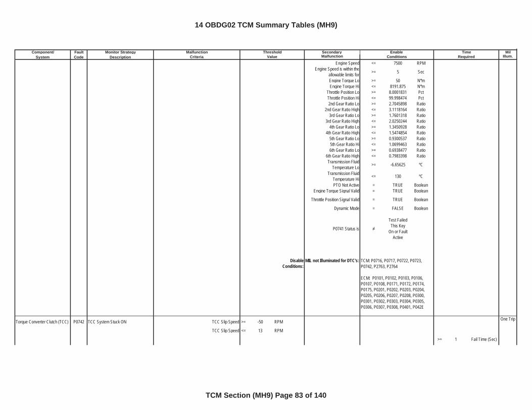
Component/ Fault Monitor Strategy Secondary MilSystem Code Description Malfunction Illum.
Malfunction Threshold Enable TimeCriteria Value Conditions Required
Engine Speed <= 7500 RPMEngine Speed is within the
allowable limits for >= 5 Sec
Engine Torque Lo >= 50 N*mEngine Torque Hi <= 8191.875 N*m
Throttle Position Lo >= 8.0001831 PctThrottle Position Hi <= 99.998474 Pct2nd Gear Ratio Lo >= 2.7045898 Ratio
2nd Gear Ratio High <= 3.1118164 Ratio3rd Gear Ratio Lo >= 1.7601318 Ratio
3rd Gear Ratio High <= 2.0250244 Ratio4th Gear Ratio Lo >= 1.3450928 Ratio
4th Gear Ratio High <= 1.5474854 Ratio5th Gear Ratio Lo >= 0.9300537 Ratio5th Gear Ratio Hi <= 1.0699463 Ratio6th Gear Ratio Lo >= 0.6938477 Ratio
6th Gear Ratio High <= 0.7983398 RatioTransmission Fluid
Temperature Lo >= -6.65625 ºC
Transmission Fluid Temperature Hi <= 130 ºC
PTO Not Active = TRUE BooleanEngine Torque Signal Valid = TRUE Boolean
Throttle Position Signal Valid = TRUE Boolean
Dynamic Mode = FALSE Boolean
P0741 Status is
Test Failed This Key
On or Fault Active
DisableConditions:
MIL not Illuminated for DTC's:
Torque Converter Clutch (TCC) P0742 TCC System Stuck ON TCC Slip Speed >= -50 RPM One Trip
TCC Slip Speed <= 13 RPM
>= 1 Fail Time (Sec)
TCM: P0716, P0717, P0722, P0723,P0742, P2763, P2764
ECM: P0101, P0102, P0103, P0106, P0107, P0108, P0171, P0172, P0174, P0175, P0201, P0202, P0203, P0204, P0205, P0206, P0207, P0208, P0300, P0301, P0302, P0303, P0304, P0305, P0306, P0307, P0308, P0401, P042E
14 OBDG02 TCM Summary Tables (MH9)
TCM Section (MH9) Page 83 of 140
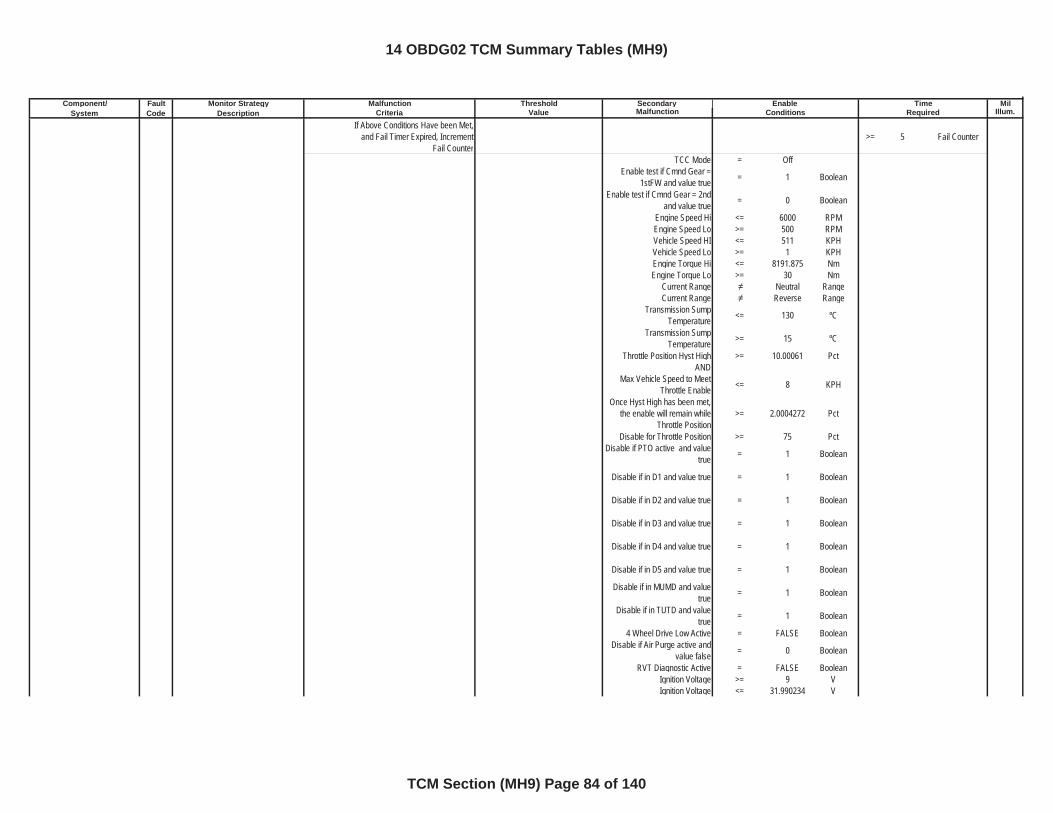
Component/ Fault Monitor Strategy Secondary MilSystem Code Description Malfunction Illum.
Malfunction Threshold Enable TimeCriteria Value Conditions Required
If Above Conditions Have been Met, and Fail Timer Expired, Increment
Fail Counter>= 5 Fail Counter
TCC Mode = OffEnable test if Cmnd Gear =
1stFW and value true = 1 Boolean
Enable test if Cmnd Gear = 2nd and value true = 0 Boolean
Engine Speed Hi <= 6000 RPMEngine Speed Lo >= 500 RPMVehicle Speed HI <= 511 KPHVehicle Speed Lo >= 1 KPHEngine Torque Hi <= 8191.875 NmEngine Torque Lo >= 30 Nm
Current Range Neutral RangeCurrent Range Reverse Range
Transmission Sump Temperature <= 130 ºC
Transmission Sump Temperature >= 15 ºC
Throttle Position Hyst High >= 10.00061 PctAND
Max Vehicle Speed to Meet Throttle Enable <= 8 KPH
Once Hyst High has been met, the enable will remain while
Throttle Position>= 2.0004272 Pct
Disable for Throttle Position >= 75 PctDisable if PTO active and value
true = 1 Boolean
Disable if in D1 and value true = 1 Boolean
Disable if in D2 and value true = 1 Boolean
Disable if in D3 and value true = 1 Boolean
Disable if in D4 and value true = 1 Boolean
Disable if in D5 and value true = 1 Boolean
Disable if in MUMD and value true = 1 Boolean
Disable if in TUTD and value true = 1 Boolean
4 Wheel Drive Low Active = FALSE BooleanDisable if Air Purge active and
value false = 0 Boolean
RVT Diagnostic Active = FALSE BooleanIgnition Voltage >= 9 VIgnition Voltage <= 31.990234 V
14 OBDG02 TCM Summary Tables (MH9)
TCM Section (MH9) Page 84 of 140
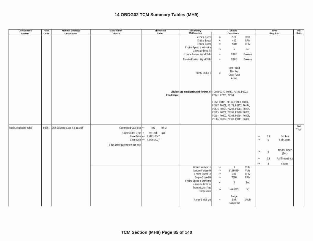
Component/ Fault Monitor Strategy Secondary MilSystem Code Description Malfunction Illum.
Malfunction Threshold Enable TimeCriteria Value Conditions Required
Vehicle Speed <= 511 KPHEngine Speed >= 400 RPMEngine Speed <= 7500 RPM
Engine Speed is within the allowable limits for >= 5 Sec
Engine Torque Signal Valid = TRUE Boolean
Throttle Position Signal Valid = TRUE Boolean
P0742 Status is
Test Failed This Key
On or Fault Active
DisableConditions:
MIL not Illuminated for DTC's:
Mode 2 Multiplex Valve P0751 Shift Solenoid Valve A Stuck Off Commaned Gear Slip >= 400 RPM TwoTrips
Commanded Gear = 1st Lock rpmGear Ratio <= 1.518310547 >= 0.3 Fail TmrGear Ratio >= 1.373657227 = 5 Fail Counts
If the above parameters are true
0 Neutral Timer (Sec)
>= 0.3 Fail Timer (Sec)
>= 8 CountsIgnition Voltage Lo >= 9 VoltsIgnition Voltage Hi <= 31.990234 VoltsEngine Speed Lo >= 400 RPMEngine Speed Hi <= 7500 RPM
Engine Speed is within the allowable limits for >= 5 Sec
Transmission Fluid Temperature >= -6.65625 ºC
Range Shift State =RangeShift
CompletedENUM
TCM: P0716, P0717, P0722, P0723, P0741, P2763, P2764
ECM: P0101, P0102, P0103, P0106, P0107, P0108, P0171, P0172, P0174, P0175, P0201, P0202, P0203, P0204, P0205, P0206, P0207, P0208, P0300, P0301, P0302, P0303, P0304, P0305, P0306, P0307, P0308, P0401, P042E
14 OBDG02 TCM Summary Tables (MH9)
TCM Section (MH9) Page 85 of 140
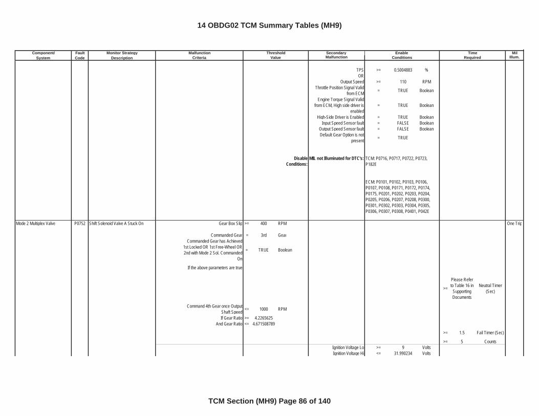
Component/ Fault Monitor Strategy Secondary MilSystem Code Description Malfunction Illum.
Malfunction Threshold Enable TimeCriteria Value Conditions Required
TPS >= 0.5004883 %OR
Output Speed >= 110 RPMThrottle Position Signal Valid
from ECM = TRUE Boolean
Engine Torque Signal Valid from ECM, High side driver is
enabled= TRUE Boolean
High-Side Driver is Enabled = TRUE BooleanInput Speed Sensor fault = FALSE Boolean
Output Speed Sensor fault = FALSE BooleanDefault Gear Option is not
present = TRUE
DisableConditions:
MIL not Illuminated for DTC's:
Mode 2 Multiplex Valve P0752 Shift Solenoid Valve A Stuck On Gear Box Slip >= 400 RPM One Trip
Commanded Gear = 3rd GearCommanded Gear has Achieved
1st Locked OR 1st Free-Wheel OR 2nd with Mode 2 Sol. Commanded
On
= TRUE Boolean
If the above parameters are true
>=
Please Refer to Table 16 in
SupportingDocuments
Neutral Timer (Sec)
Command 4th Gear once Output Shaft Speed <= 1000 RPM
If Gear Ratio >= 4.2265625And Gear Ratio <= 4.671508789
>= 1.5 Fail Timer (Sec)
>= 5 CountsIgnition Voltage Lo >= 9 VoltsIgnition Voltage Hi <= 31.990234 Volts
TCM: P0716, P0717, P0722, P0723, P182E
ECM: P0101, P0102, P0103, P0106, P0107, P0108, P0171, P0172, P0174, P0175, P0201, P0202, P0203, P0204, P0205, P0206, P0207, P0208, P0300, P0301, P0302, P0303, P0304, P0305, P0306, P0307, P0308, P0401, P042E
14 OBDG02 TCM Summary Tables (MH9)
TCM Section (MH9) Page 86 of 140
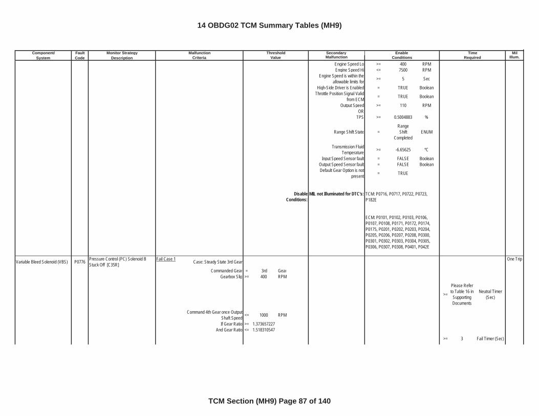
Component/ Fault Monitor Strategy Secondary MilSystem Code Description Malfunction Illum.
Malfunction Threshold Enable TimeCriteria Value Conditions Required
Engine Speed Lo >= 400 RPMEngine Speed Hi <= 7500 RPM
Engine Speed is within the allowable limits for >= 5 Sec
High-Side Driver is Enabled = TRUE BooleanThrottle Position Signal Valid
from ECM = TRUE Boolean
Output Speed >= 110 RPMOR
TPS >= 0.5004883 %
Range Shift State =RangeShift
CompletedENUM
Transmission Fluid Temperature >= -6.65625 ºC
Input Speed Sensor fault = FALSE BooleanOutput Speed Sensor fault = FALSE BooleanDefault Gear Option is not
present = TRUE
DisableConditions:
MIL not Illuminated for DTC's:
Variable Bleed Solenoid (VBS) P0776 Pressure Control (PC) Solenoid B Stuck Off [C35R]
Fail Case 1 Case: Steady State 3rd Gear One Trip
Commanded Gear = 3rd GearGearbox Slip >= 400 RPM
>=
Please Refer to Table 16 in
SupportingDocuments
Neutral Timer (Sec)
Command 4th Gear once Output Shaft Speed <= 1000 RPM
If Gear Ratio >= 1.373657227And Gear Ratio <= 1.518310547
>= 3 Fail Timer (Sec)
TCM: P0716, P0717, P0722, P0723, P182E
ECM: P0101, P0102, P0103, P0106, P0107, P0108, P0171, P0172, P0174, P0175, P0201, P0202, P0203, P0204, P0205, P0206, P0207, P0208, P0300, P0301, P0302, P0303, P0304, P0305, P0306, P0307, P0308, P0401, P042E
14 OBDG02 TCM Summary Tables (MH9)
TCM Section (MH9) Page 87 of 140
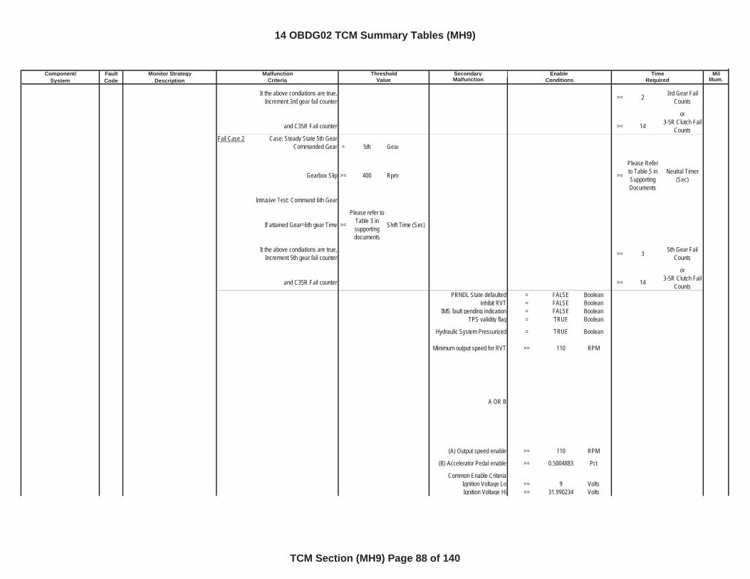
Component/ Fault Monitor Strategy Secondary MilSystem Code Description Malfunction Illum.
Malfunction Threshold Enable TimeCriteria Value Conditions Required
It the above condiations are true, Increment 3rd gear fail counter >= 2 3rd Gear Fail
Counts
or
and C35R Fail counter >= 14 3-5R Clutch Fail Counts
Fail Case 2 Case: Steady State 5th GearCommanded Gear = 5th Gear
Gearbox Slip >= 400 Rpm >=
Please Refer to Table 5 in SupportingDocuments
Neutral Timer (Sec)
Intrusive Test: Command 6th Gear
If attained Gear=6th gear Time >=
Please refer to Table 3 insupportingdocuments
Shift Time (Sec)
It the above condiations are true, Increment 5th gear fail counter >= 3 5th Gear Fail
Counts
or
and C35R Fail counter >= 14 3-5R Clutch Fail Counts
PRNDL State defaulted = FALSE Booleaninhibit RVT = FALSE Boolean
IMS fault pending indication = FALSE BooleanTPS validity flag = TRUE Boolean
Hydraulic System Pressurized = TRUE Boolean
Minimum output speed for RVT >= 110 RPM
A OR B
(A) Output speed enable >= 110 RPM
(B) Accelerator Pedal enable >= 0.5004883 Pct
Common Enable CriteriaIgnition Voltage Lo >= 9 VoltsIgnition Voltage Hi <= 31.990234 Volts
14 OBDG02 TCM Summary Tables (MH9)
TCM Section (MH9) Page 88 of 140
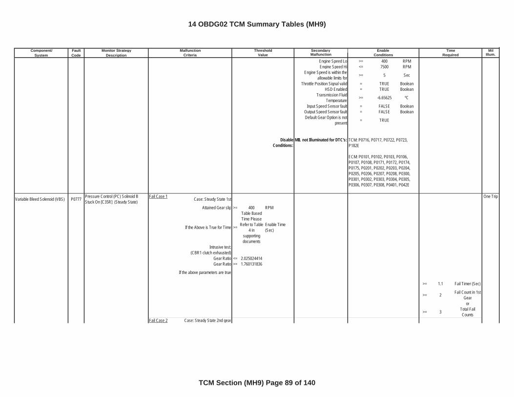
Component/ Fault Monitor Strategy Secondary MilSystem Code Description Malfunction Illum.
Malfunction Threshold Enable TimeCriteria Value Conditions Required
Engine Speed Lo >= 400 RPMEngine Speed Hi <= 7500 RPM
Engine Speed is within the allowable limits for >= 5 Sec
Throttle Position Signal valid = TRUE BooleanHSD Enabled = TRUE Boolean
Transmission Fluid Temperature >= -6.65625 ºC
Input Speed Sensor fault = FALSE BooleanOutput Speed Sensor fault = FALSE BooleanDefault Gear Option is not
present = TRUE
DisableConditions:
MIL not Illuminated for DTC's:
Variable Bleed Solenoid (VBS) P0777 Pressure Control (PC) Solinoid B Stuck On [C35R] (Steady State)
Fail Case 1 Case: Steady State 1st One Trip
Attained Gear slip >= 400 RPM
If the Above is True for Time >=
Table Based Time Please
Refer to Table 4 in
supportingdocuments
Enable Time (Sec)
Intrusive test:(CBR1 clutch exhausted)
Gear Ratio <= 2.025024414Gear Ratio >= 1.760131836
If the above parameters are true
>= 1.1 Fail Timer (Sec)
>= 2 Fail Count in 1st Gear
or
>= 3 Total Fail Counts
Fail Case 2 Case: Steady State 2nd gear
TCM: P0716, P0717, P0722, P0723, P182E
ECM: P0101, P0102, P0103, P0106, P0107, P0108, P0171, P0172, P0174, P0175, P0201, P0202, P0203, P0204, P0205, P0206, P0207, P0208, P0300, P0301, P0302, P0303, P0304, P0305, P0306, P0307, P0308, P0401, P042E
14 OBDG02 TCM Summary Tables (MH9)
TCM Section (MH9) Page 89 of 140
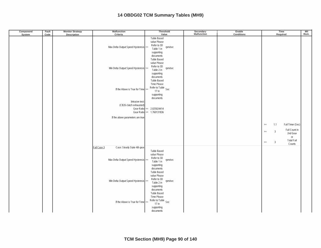
Component/ Fault Monitor Strategy Secondary MilSystem Code Description Malfunction Illum.
Malfunction Threshold Enable TimeCriteria Value Conditions Required
Max Delta Output Speed Hysteresis >=
Table Based value Please Refer to 3D Table 1 in supportingdocuments
rpm/sec
Min Delta Output Speed Hysteresis >=
Table Based value Please Refer to 3D Table 2 in supportingdocuments
rpm/sec
If the Above is True for Time >=
Table Based Time Please
Refer to Table 17 in
supportingdocuments
Sec
Intrusive test: (CB26 clutch exhausted)
Gear Ratio <= 2.025024414Gear Ratio >= 1.760131836
If the above parameters are true
>= 1.1 Fail Timer (Sec)
>= 3 Fail Count in 2nd Gear
or
>= 3 Total Fail Counts
Fail Case 3 Case: Steady State 4th gear
Max Delta Output Speed Hysteresis >=
Table Based value Please Refer to 3D Table 1 in supportingdocuments
rpm/sec
Min Delta Output Speed Hysteresis >=
Table Based value Please Refer to 3D Table 2 in supportingdocuments
rpm/sec
If the Above is True for Time >=
Table Based Time Please
Refer to Table 17 in
supportingdocuments
Sec
14 OBDG02 TCM Summary Tables (MH9)
TCM Section (MH9) Page 90 of 140
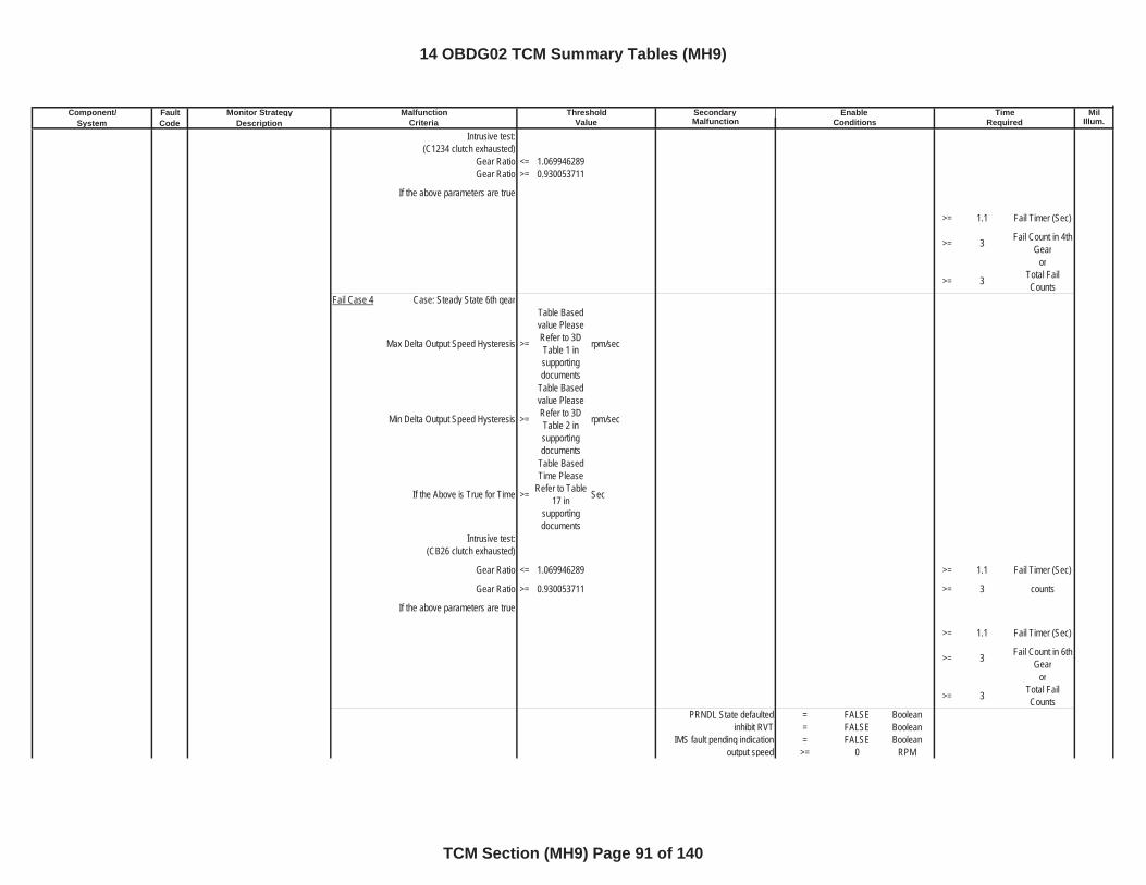
Component/ Fault Monitor Strategy Secondary MilSystem Code Description Malfunction Illum.
Malfunction Threshold Enable TimeCriteria Value Conditions Required
Intrusive test: (C1234 clutch exhausted)
Gear Ratio <= 1.069946289Gear Ratio >= 0.930053711
If the above parameters are true
>= 1.1 Fail Timer (Sec)
>= 3 Fail Count in 4th Gear
or
>= 3 Total Fail Counts
Fail Case 4 Case: Steady State 6th gear
Max Delta Output Speed Hysteresis >=
Table Based value Please Refer to 3D Table 1 in supportingdocuments
rpm/sec
Min Delta Output Speed Hysteresis >=
Table Based value Please Refer to 3D Table 2 in supportingdocuments
rpm/sec
If the Above is True for Time >=
Table Based Time Please
Refer to Table 17 in
supportingdocuments
Sec
Intrusive test: (CB26 clutch exhausted)
Gear Ratio <= 1.069946289 >= 1.1 Fail Timer (Sec)
Gear Ratio >= 0.930053711 >= 3 counts
If the above parameters are true
>= 1.1 Fail Timer (Sec)
>= 3 Fail Count in 6th Gear
or
>= 3 Total Fail Counts
PRNDL State defaulted = FALSE Booleaninhibit RVT = FALSE Boolean
IMS fault pending indication = FALSE Booleanoutput speed >= 0 RPM
14 OBDG02 TCM Summary Tables (MH9)
TCM Section (MH9) Page 91 of 140
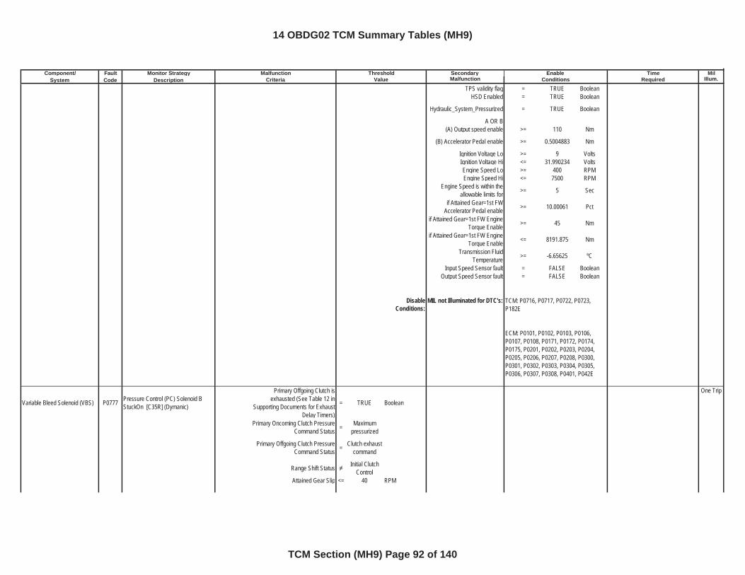
Component/ Fault Monitor Strategy Secondary MilSystem Code Description Malfunction Illum.
Malfunction Threshold Enable TimeCriteria Value Conditions Required
TPS validity flag = TRUE BooleanHSD Enabled = TRUE Boolean
Hydraulic_System_Pressurized = TRUE Boolean
A OR B(A) Output speed enable >= 110 Nm
(B) Accelerator Pedal enable >= 0.5004883 Nm
Ignition Voltage Lo >= 9 VoltsIgnition Voltage Hi <= 31.990234 VoltsEngine Speed Lo >= 400 RPMEngine Speed Hi <= 7500 RPM
Engine Speed is within the allowable limits for >= 5 Sec
if Attained Gear=1st FW Accelerator Pedal enable >= 10.00061 Pct
if Attained Gear=1st FW Engine Torque Enable >= 45 Nm
if Attained Gear=1st FW Engine Torque Enable <= 8191.875 Nm
Transmission Fluid Temperature >= -6.65625 ºC
Input Speed Sensor fault = FALSE BooleanOutput Speed Sensor fault = FALSE Boolean
DisableConditions:
MIL not Illuminated for DTC's:
Variable Bleed Solenoid (VBS) P0777 Pressure Control (PC) Solenoid B StuckOn [C35R] (Dymanic)
Primary Offgoing Clutch is exhausted (See Table 12 in
Supporting Documents for Exhaust Delay Timers)
= TRUE Boolean
One Trip
Primary Oncoming Clutch Pressure Command Status = Maximum
pressurized
Primary Offgoing Clutch Pressure Command Status = Clutch exhaust
command
Range Shift Status Initial Clutch Control
Attained Gear Slip <= 40 RPM
TCM: P0716, P0717, P0722, P0723, P182E
ECM: P0101, P0102, P0103, P0106, P0107, P0108, P0171, P0172, P0174, P0175, P0201, P0202, P0203, P0204, P0205, P0206, P0207, P0208, P0300, P0301, P0302, P0303, P0304, P0305, P0306, P0307, P0308, P0401, P042E
14 OBDG02 TCM Summary Tables (MH9)
TCM Section (MH9) Page 92 of 140
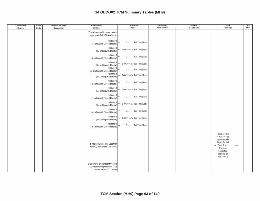
Component/ Fault Monitor Strategy Secondary MilSystem Code Description Malfunction Illum.
Malfunction Threshold Enable TimeCriteria Value Conditions Required
If the above conditions are true run appropriate Fail 1 Timers Below:
fail timer 1(3-1 shifting with Closed Throttle) >= 0.5 Fail Time (Sec)
fail timer 1(3-2 shifting with Throttle) >= 0.400390625 Fail Time (Sec)
fail timer 1(3-2 shifting with Closed Throttle) >= 0.5 Fail Time (Sec)
fail timer 1(3-4 shifting with Throttle) >= 0.400390625 Fail Time (Sec)
fail timer 1(3-4shifting with Closed Throttle) >= 0.5 Fail Time (Sec)
fail timer 1(3-5 shifting with Throttle) >= 0.400390625 Fail Time (Sec)
fail timer 1(3-5 shifting with Closed Throttle) >= 0.5 Fail Time (Sec)
fail timer 1(5-3 shifting with Throttle) >= 0.400390625 Fail Time (Sec)
fail timer 1(5-3 shifting with Closed Throttle) >= 0.5 Fail Time (Sec)
fail timer 1(5-4 shifting with Throttle) >= 0.400390625 Fail Time (Sec)
fail timer 1(5-4 shifting with Closed Throttle) >= 0.5 Fail Time (Sec)
fail timer 1(5-6 shifting with Throttle) >= 0.400390625 Fail Time (Sec)
fail timer 1(5-6 shifting with Closed Throttle) >= 0.5 Fail Time (Sec)
If Attained Gear Slip is Less than Above Cal Increment Fail Timers >=
Total Fail Time = (Fail 1 + Fail 2) See Enable Timers for Fail Timer 1, and ReferenceSupportingTable 15 for Fail Timer 2
sec
If fail timer is greater than threshold increment corresponding gear fail
counter and total fail counter
14 OBDG02 TCM Summary Tables (MH9)
TCM Section (MH9) Page 93 of 140
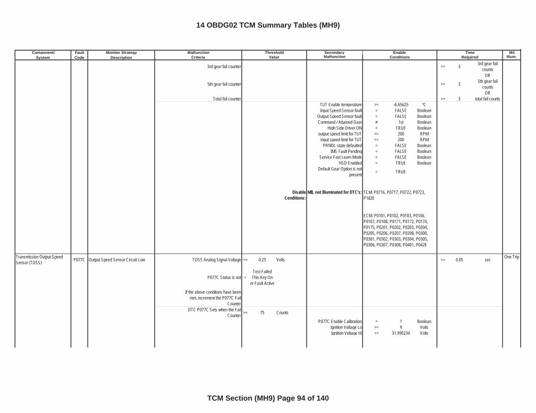
Component/ Fault Monitor Strategy Secondary MilSystem Code Description Malfunction Illum.
Malfunction Threshold Enable TimeCriteria Value Conditions Required
3rd gear fail counter >= 3 3rd gear fail counts
OR
5th gear fail counter >= 3 5th gear fail counts
ORTotal fail counter >= 3 total fail counts
TUT Enable temperature >= -6.65625 ºCInput Speed Sensor fault = FALSE Boolean
Output Speed Sensor fault = FALSE BooleanCommand / Attained Gear 1st Boolean
High Side Driver ON = TRUE Booleanoutput speed limit for TUT >= 200 RPM
input speed limit for TUT >= 200 RPMPRNDL state defaulted = FALSE Boolean
IMS Fault Pending = FALSE BooleanService Fast Learn Mode = FALSE Boolean
HSD Enabled = TRUE BooleanDefault Gear Option is not
present = TRUE
DisableConditions:
MIL not Illuminated for DTC's:
Transmission Output Speed Sensor (TOSS) P077C Output Speed Sensor Circuit Low TOSS Analog Signal Voltage <= 0.25 Volts >= 0.05 sec One Trip
P077C Status is not =Test Failed
This Key On or Fault Active
If the above conditons have been met, increment the P077C Fail
CounterDTC P077C Sets when the Fail
Counter >= 75 Counts
P077C Enable Calibration = 1 BooleanIgnition Voltage Lo >= 9 VoltsIgnition Voltage Hi <= 31.990234 Volts
TCM: P0716, P0717, P0722, P0723, P182E
ECM: P0101, P0102, P0103, P0106, P0107, P0108, P0171, P0172, P0174, P0175, P0201, P0202, P0203, P0204, P0205, P0206, P0207, P0208, P0300, P0301, P0302, P0303, P0304, P0305, P0306, P0307, P0308, P0401, P042E
14 OBDG02 TCM Summary Tables (MH9)
TCM Section (MH9) Page 94 of 140
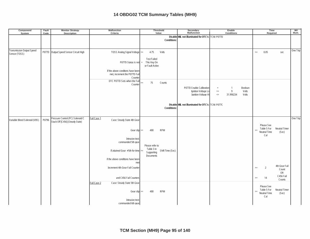
Component/ Fault Monitor Strategy Secondary MilSystem Code Description Malfunction Illum.
Malfunction Threshold Enable TimeCriteria Value Conditions Required
DisableConditions:
MIL not Illuminated for DTC's:
Transmission Output Speed Sensor (TOSS) P077D Output Speed Sensor Circuit High TOSS Analog Signal Voltage >= 4.75 Volts >= 0.05 sec One Trip
P077D Status is not =Test Failed
This Key On or Fault Active
If the above conditons have been met, increment the P077D Fail
CounterDTC P077D Sets when the Fail
Counter >= 75 Counts
P077D Enable Calibration = 1 BooleanIgnition Voltage Lo >= 9 VoltsIgnition Voltage Hi <= 31.990234 Volts
DisableConditions:
MIL not Illuminated for DTC's:
Variable Bleed Solenoid (VBS) P0796 Pressure Control (PC) Solenoid C Stuck Off [C456] (Steady State)
Fail Case 1 Case: Steady State 4th Gear One Trip
Gear slip >= 400 RPM >=
Please See Table 5 For
Neutral Time Cal
Neutral Timer (Sec)
Intrusive test:commanded 5th gear
If attained Gear 5th for time >=
Please refer to Table 3 in SupportingDocuments
Shift Time (Sec)
if the above conditions have been met
Increment 4th Gear Fail Counter >= 2 4th Gear Fail Count
OR
and C456 Fail Counters >= 14 C456 Fail Counts
Fail Case 2 Case: Steady State 5th Gear
Gear slip >= 400 RPM >=
Please See Table 5 For
Neutral Time Cal
Neutral Timer (Sec)
Intrusive test:commanded 6th gear
TCM: P077D
TCM: P077C
14 OBDG02 TCM Summary Tables (MH9)
TCM Section (MH9) Page 95 of 140
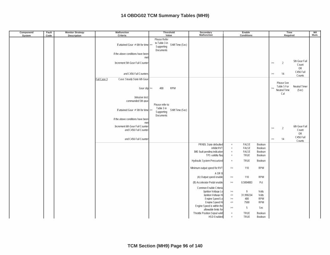
Component/ Fault Monitor Strategy Secondary MilSystem Code Description Malfunction Illum.
Malfunction Threshold Enable TimeCriteria Value Conditions Required
If attained Gear 6th for time >=
Please Refer to Table 3 in SupportingDocuments
Shift Time (Sec)
if the above conditions have been met
Increment 5th Gear Fail Counter >= 2 5th Gear Fail Count
OR
and C456 Fail Counters >= 14 C456 Fail Counts
Fail Case 3 Case: Steady State 6th Gear
Gear slip >= 400 RPM >=
Please See Table 5 For
Neutral Time Cal
Neutral Timer (Sec)
Intrusive test:commanded 5th gear
If attained Gear 5th for time >=
Please refer to Table 3 in SupportingDocuments
Shift Time (Sec)
if the above conditions have been met
Increment 6th Gear Fail Counter and C456 Fail Counter >= 2 6th Gear Fail
CountOR
and C456 Fail Counter >= 14 C456 Fail Counts
PRNDL State defaulted = FALSE Booleaninhibit RVT = FALSE Boolean
IMS fault pending indication = FALSE BooleanTPS validity flag = TRUE Boolean
Hydraulic System Pressurized = TRUE Boolean
Minimum output speed for RVT >= 110 RPM
A OR B(A) Output speed enable >= 110 RPM
(B) Accelerator Pedal enable >= 0.5004883 Pct
Common Enable CriteriaIgnition Voltage Lo >= 9 VoltsIgnition Voltage Hi <= 31.990234 VoltsEngine Speed Lo >= 400 RPMEngine Speed Hi <= 7500 RPM
Engine Speed is within the allowable limits for >= 5 Sec
Throttle Position Signal valid = TRUE BooleanHSD Enabled = TRUE Boolean
14 OBDG02 TCM Summary Tables (MH9)
TCM Section (MH9) Page 96 of 140
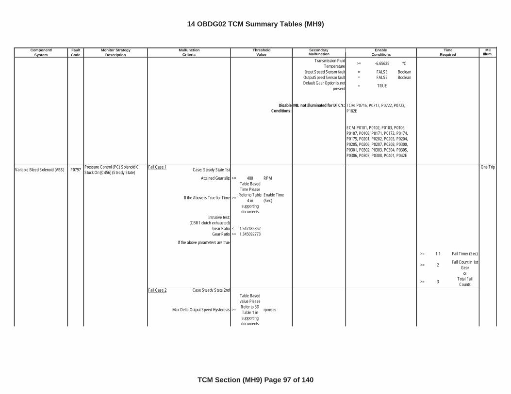
Component/ Fault Monitor Strategy Secondary MilSystem Code Description Malfunction Illum.
Malfunction Threshold Enable TimeCriteria Value Conditions Required
Transmission Fluid Temperature >= -6.65625 ºC
Input Speed Sensor fault = FALSE BooleanOutputSpeed Sensor fault = FALSE BooleanDefault Gear Option is not
present = TRUE
DisableConditions:
MIL not Illuminated for DTC's:
Variable Bleed Solenoid (VBS) P0797 Pressure Control (PC) Solenoid C Stuck On [C456] (Steady State)
Fail Case 1 Case: Steady State 1st One Trip
Attained Gear slip >= 400 RPM
If the Above is True for Time >=
Table Based Time Please
Refer to Table 4 in
supportingdocuments
Enable Time (Sec)
Intrusive test:(CBR1 clutch exhausted)
Gear Ratio <= 1.547485352Gear Ratio >= 1.345092773
If the above parameters are true
>= 1.1 Fail Timer (Sec)
>= 2 Fail Count in 1st Gear
or
>= 3 Total Fail Counts
Fail Case 2 Case Steady State 2nd
Max Delta Output Speed Hysteresis >=
Table Based value Please Refer to 3D Table 1 in supportingdocuments
rpm/sec
TCM: P0716, P0717, P0722, P0723, P182E
ECM: P0101, P0102, P0103, P0106, P0107, P0108, P0171, P0172, P0174, P0175, P0201, P0202, P0203, P0204, P0205, P0206, P0207, P0208, P0300, P0301, P0302, P0303, P0304, P0305, P0306, P0307, P0308, P0401, P042E
14 OBDG02 TCM Summary Tables (MH9)
TCM Section (MH9) Page 97 of 140
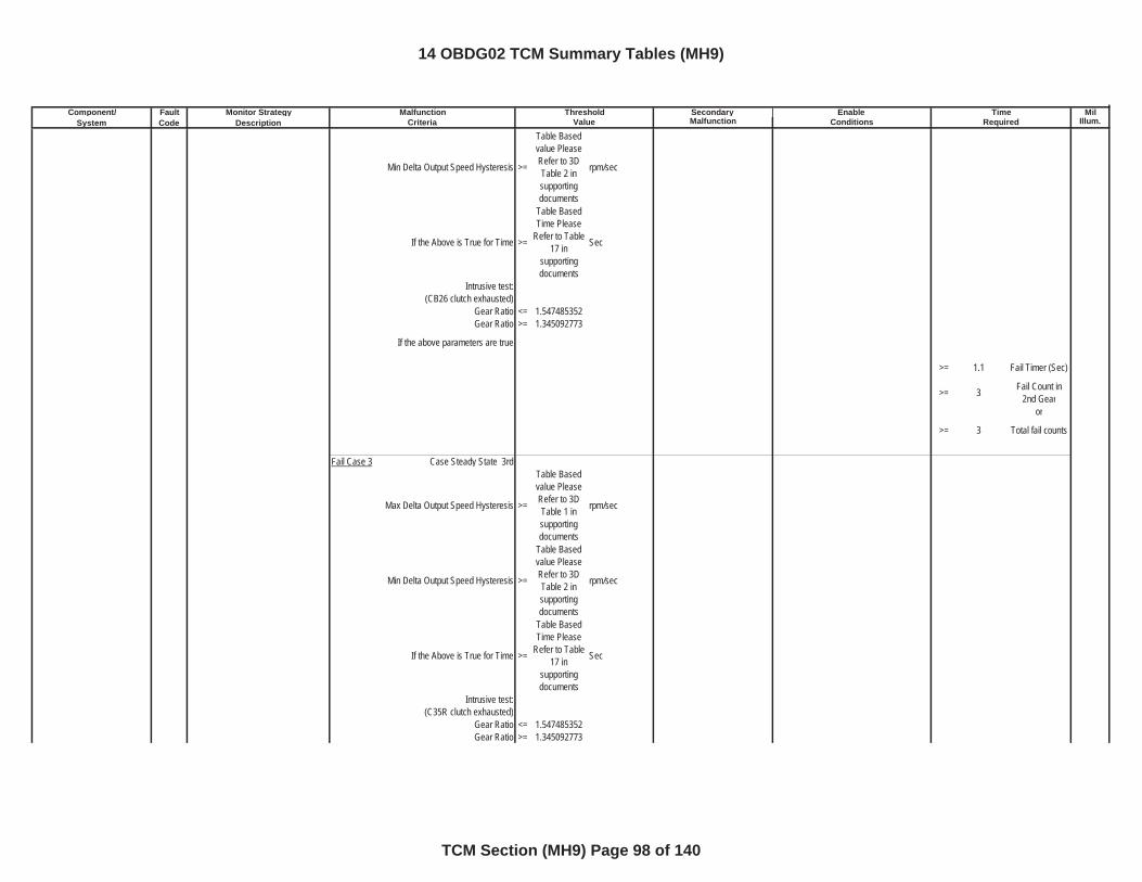
Component/ Fault Monitor Strategy Secondary MilSystem Code Description Malfunction Illum.
Malfunction Threshold Enable TimeCriteria Value Conditions Required
Min Delta Output Speed Hysteresis >=
Table Based value Please Refer to 3D Table 2 in supportingdocuments
rpm/sec
If the Above is True for Time >=
Table Based Time Please
Refer to Table 17 in
supportingdocuments
Sec
Intrusive test: (CB26 clutch exhausted)
Gear Ratio <= 1.547485352Gear Ratio >= 1.345092773
If the above parameters are true
>= 1.1 Fail Timer (Sec)
>= 3 Fail Count in 2nd Gear
or
>= 3 Total fail counts
Fail Case 3 Case Steady State 3rd
Max Delta Output Speed Hysteresis >=
Table Based value Please Refer to 3D Table 1 in supportingdocuments
rpm/sec
Min Delta Output Speed Hysteresis >=
Table Based value Please Refer to 3D Table 2 in supportingdocuments
rpm/sec
If the Above is True for Time >=
Table Based Time Please
Refer to Table 17 in
supportingdocuments
Sec
Intrusive test: (C35R clutch exhausted)
Gear Ratio <= 1.547485352Gear Ratio >= 1.345092773
14 OBDG02 TCM Summary Tables (MH9)
TCM Section (MH9) Page 98 of 140
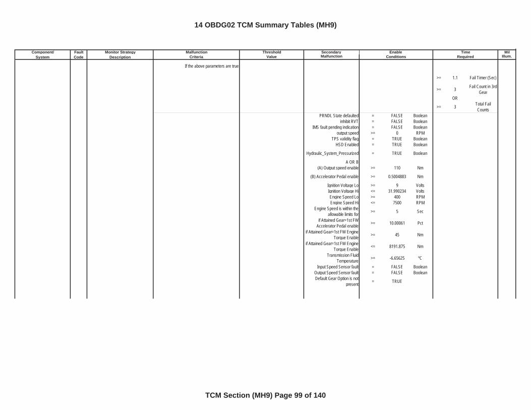
Component/ Fault Monitor Strategy Secondary MilSystem Code Description Malfunction Illum.
Malfunction Threshold Enable TimeCriteria Value Conditions Required
If the above parameters are true
>= 1.1 Fail Timer (Sec)
>= 3 Fail Count in 3rd Gear
OR
>= 3 Total Fail Counts
PRNDL State defaulted = FALSE Booleaninhibit RVT = FALSE Boolean
IMS fault pending indication = FALSE Booleanoutput speed >= 0 RPM
TPS validity flag = TRUE BooleanHSD Enabled = TRUE Boolean
Hydraulic_System_Pressurized = TRUE Boolean
A OR B(A) Output speed enable >= 110 Nm
(B) Accelerator Pedal enable >= 0.5004883 Nm
Ignition Voltage Lo >= 9 VoltsIgnition Voltage Hi <= 31.990234 VoltsEngine Speed Lo >= 400 RPMEngine Speed Hi <= 7500 RPM
Engine Speed is within the allowable limits for >= 5 Sec
if Attained Gear=1st FW Accelerator Pedal enable >= 10.00061 Pct
if Attained Gear=1st FW Engine Torque Enable >= 45 Nm
if Attained Gear=1st FW Engine Torque Enable <= 8191.875 Nm
Transmission Fluid Temperature >= -6.65625 ºC
Input Speed Sensor fault = FALSE BooleanOutput Speed Sensor fault = FALSE BooleanDefault Gear Option is not
present = TRUE
14 OBDG02 TCM Summary Tables (MH9)
TCM Section (MH9) Page 99 of 140
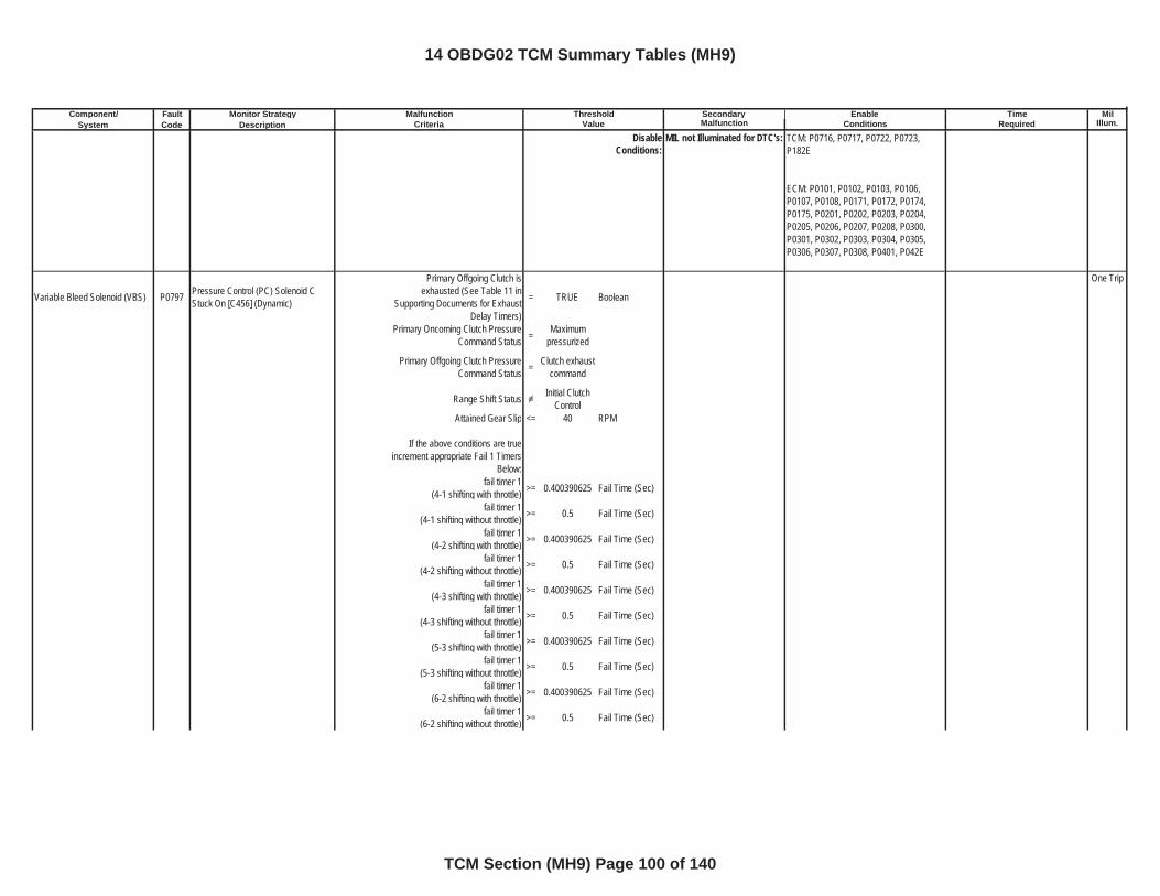
Component/ Fault Monitor Strategy Secondary MilSystem Code Description Malfunction Illum.
Malfunction Threshold Enable TimeCriteria Value Conditions Required
DisableConditions:
MIL not Illuminated for DTC's:
Variable Bleed Solenoid (VBS) P0797 Pressure Control (PC) Solenoid C Stuck On [C456] (Dynamic)
Primary Offgoing Clutch is exhausted (See Table 11 in
Supporting Documents for Exhaust Delay Timers)
= TRUE Boolean
One Trip
Primary Oncoming Clutch Pressure Command Status = Maximum
pressurized
Primary Offgoing Clutch Pressure Command Status = Clutch exhaust
command
Range Shift Status Initial Clutch Control
Attained Gear Slip <= 40 RPM
If the above conditions are true increment appropriate Fail 1 Timers
Below:fail timer 1
(4-1 shifting with throttle) >= 0.400390625 Fail Time (Sec)
fail timer 1(4-1 shifting without throttle) >= 0.5 Fail Time (Sec)
fail timer 1(4-2 shifting with throttle) >= 0.400390625 Fail Time (Sec)
fail timer 1(4-2 shifting without throttle) >= 0.5 Fail Time (Sec)
fail timer 1(4-3 shifting with throttle) >= 0.400390625 Fail Time (Sec)
fail timer 1(4-3 shifting without throttle) >= 0.5 Fail Time (Sec)
fail timer 1(5-3 shifting with throttle) >= 0.400390625 Fail Time (Sec)
fail timer 1(5-3 shifting without throttle) >= 0.5 Fail Time (Sec)
fail timer 1(6-2 shifting with throttle) >= 0.400390625 Fail Time (Sec)
fail timer 1(6-2 shifting without throttle) >= 0.5 Fail Time (Sec)
TCM: P0716, P0717, P0722, P0723, P182E
ECM: P0101, P0102, P0103, P0106, P0107, P0108, P0171, P0172, P0174, P0175, P0201, P0202, P0203, P0204, P0205, P0206, P0207, P0208, P0300, P0301, P0302, P0303, P0304, P0305, P0306, P0307, P0308, P0401, P042E
14 OBDG02 TCM Summary Tables (MH9)
TCM Section (MH9) Page 100 of 140
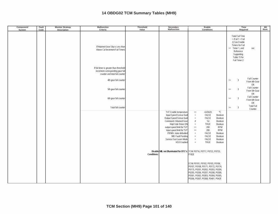
Component/ Fault Monitor Strategy Secondary MilSystem Code Description Malfunction Illum.
Malfunction Threshold Enable TimeCriteria Value Conditions Required
If Attained Gear Slip is Less than Above Cal Increment Fail Timers >=
Total Fail Time = (Fail 1 + Fail 2) See Enable Timers for Fail Timer 1, and ReferenceSupportingTable 15 for Fail Timer 2
sec
If fail timer is greater than threshold increment corresponding gear fail
counter and total fail counter
4th gear fail counter >= 3 Fail Counter From 4th Gear
OR
5th gear fail counter >= 3 Fail Counter From 5th Gear
OR
6th gear fail counter >= 3 Fail Counter From 6th Gear
OR
Total fail counter >= 3 Total Fail Counter
TUT Enable temperature >= -6.65625 ºCInput Speed Sensor fault = FALSE Boolean
Output Speed Sensor fault = FALSE BooleanCommand / Attained Gear 1st Boolean
High Side Driver ON = TRUE Booleanoutput speed limit for TUT >= 200 RPM
input speed limit for TUT >= 200 RPMPRNDL state defaulted = FALSE Boolean
IMS Fault Pending = FALSE BooleanService Fast Learn Mode = FALSE Boolean
HSD Enabled = TRUE Boolean
DisableConditions:
MIL not Illuminated for DTC's: TCM: P0716, P0717, P0722, P0723, P182E
ECM: P0101, P0102, P0103, P0106, P0107, P0108, P0171, P0172, P0174, P0175, P0201, P0202, P0203, P0204, P0205, P0206, P0207, P0208, P0300, P0301, P0302, P0303, P0304, P0305, P0306, P0307, P0308, P0401, P042E
14 OBDG02 TCM Summary Tables (MH9)
TCM Section (MH9) Page 101 of 140
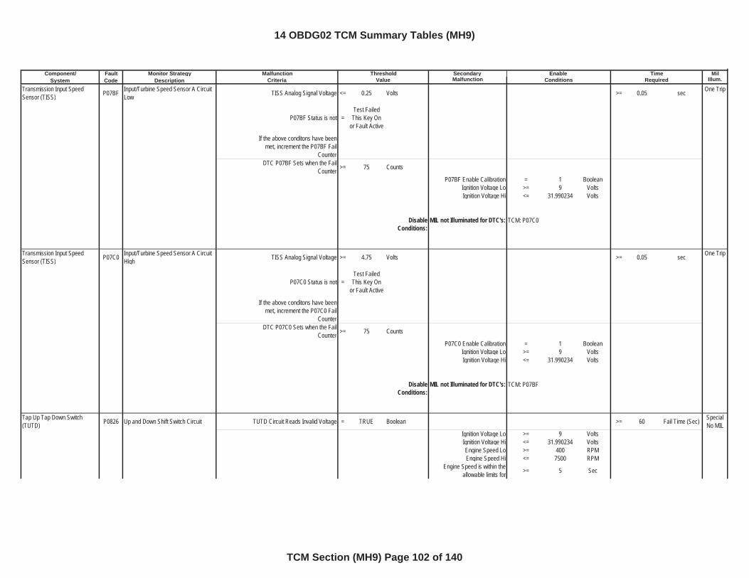
Component/ Fault Monitor Strategy Secondary MilSystem Code Description Malfunction Illum.
Malfunction Threshold Enable TimeCriteria Value Conditions Required
Transmission Input Speed Sensor (TISS) P07BF Input/Turbine Speed Sensor A Circuit
Low TISS Analog Signal Voltage <= 0.25 Volts >= 0.05 sec One Trip
P07BF Status is not =Test Failed
This Key On or Fault Active
If the above conditons have been met, increment the P07BF Fail
CounterDTC P07BF Sets when the Fail
Counter >= 75 Counts
P07BF Enable Calibration = 1 BooleanIgnition Voltage Lo >= 9 VoltsIgnition Voltage Hi <= 31.990234 Volts
DisableConditions:
MIL not Illuminated for DTC's:
Transmission Input Speed Sensor (TISS) P07C0 Input/Turbine Speed Sensor A Circuit
High TISS Analog Signal Voltage >= 4.75 Volts >= 0.05 sec One Trip
P07C0 Status is not =Test Failed
This Key On or Fault Active
If the above conditons have been met, increment the P07C0 Fail
CounterDTC P07C0 Sets when the Fail
Counter >= 75 Counts
P07C0 Enable Calibration = 1 BooleanIgnition Voltage Lo >= 9 VoltsIgnition Voltage Hi <= 31.990234 Volts
DisableConditions:
MIL not Illuminated for DTC's:
Tap Up Tap Down Switch (TUTD) P0826 Up and Down Shift Switch Circuit TUTD Circuit Reads Invalid Voltage = TRUE Boolean >= 60 Fail Time (Sec) Special
No MILIgnition Voltage Lo >= 9 VoltsIgnition Voltage Hi <= 31.990234 VoltsEngine Speed Lo >= 400 RPMEngine Speed Hi <= 7500 RPM
Engine Speed is within the allowable limits for >= 5 Sec
TCM: P07C0
TCM: P07BF
14 OBDG02 TCM Summary Tables (MH9)
TCM Section (MH9) Page 102 of 140
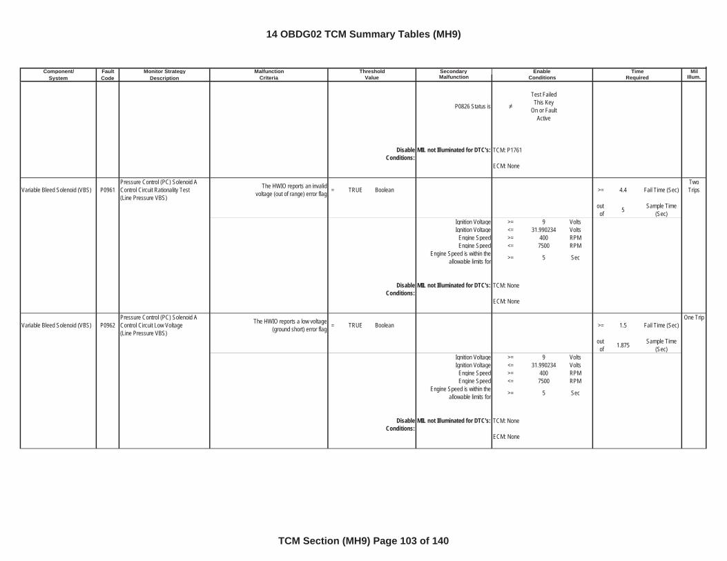
Component/ Fault Monitor Strategy Secondary MilSystem Code Description Malfunction Illum.
Malfunction Threshold Enable TimeCriteria Value Conditions Required
P0826 Status is
Test Failed This Key
On or Fault Active
DisableConditions:
MIL not Illuminated for DTC's:
Variable Bleed Solenoid (VBS) P0961Pressure Control (PC) Solenoid A Control Circuit Rationality Test(Line Pressure VBS)
The HWIO reports an invalid voltage (out of range) error flag = TRUE Boolean >= 4.4 Fail Time (Sec)
TwoTrips
outof 5 Sample Time
(Sec)Ignition Voltage >= 9 VoltsIgnition Voltage <= 31.990234 Volts
Engine Speed >= 400 RPMEngine Speed <= 7500 RPM
Engine Speed is within the allowable limits for >= 5 Sec
DisableConditions:
MIL not Illuminated for DTC's:
Variable Bleed Solenoid (VBS) P0962Pressure Control (PC) Solenoid A Control Circuit Low Voltage(Line Pressure VBS)
The HWIO reports a low voltage (ground short) error flag = TRUE Boolean >= 1.5 Fail Time (Sec)
One Trip
outof 1.875 Sample Time
(Sec)Ignition Voltage >= 9 VoltsIgnition Voltage <= 31.990234 Volts
Engine Speed >= 400 RPMEngine Speed <= 7500 RPM
Engine Speed is within the allowable limits for >= 5 Sec
DisableConditions:
MIL not Illuminated for DTC's:
TCM: P1761
ECM: None
TCM: None
ECM: None
TCM: None
ECM: None
14 OBDG02 TCM Summary Tables (MH9)
TCM Section (MH9) Page 103 of 140
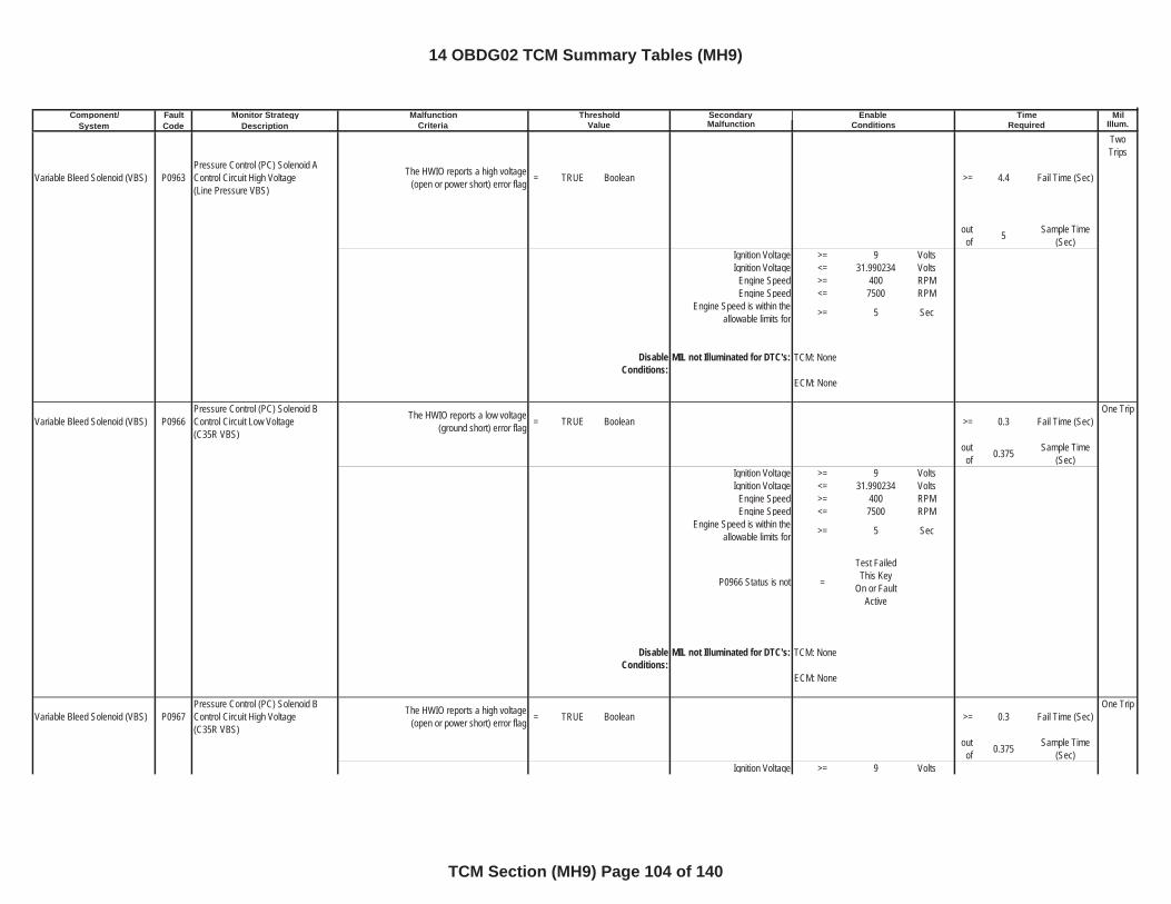
Component/ Fault Monitor Strategy Secondary MilSystem Code Description Malfunction Illum.
Malfunction Threshold Enable TimeCriteria Value Conditions Required
Variable Bleed Solenoid (VBS) P0963Pressure Control (PC) Solenoid A Control Circuit High Voltage(Line Pressure VBS)
The HWIO reports a high voltage (open or power short) error flag = TRUE Boolean >= 4.4 Fail Time (Sec)
TwoTrips
outof 5 Sample Time
(Sec)Ignition Voltage >= 9 VoltsIgnition Voltage <= 31.990234 Volts
Engine Speed >= 400 RPMEngine Speed <= 7500 RPM
Engine Speed is within the allowable limits for >= 5 Sec
DisableConditions:
MIL not Illuminated for DTC's:
Variable Bleed Solenoid (VBS) P0966Pressure Control (PC) Solenoid B Control Circuit Low Voltage(C35R VBS)
The HWIO reports a low voltage (ground short) error flag = TRUE Boolean >= 0.3 Fail Time (Sec)
One Trip
outof 0.375 Sample Time
(Sec)Ignition Voltage >= 9 VoltsIgnition Voltage <= 31.990234 Volts
Engine Speed >= 400 RPMEngine Speed <= 7500 RPM
Engine Speed is within the allowable limits for >= 5 Sec
P0966 Status is not =
Test Failed This Key
On or Fault Active
DisableConditions:
MIL not Illuminated for DTC's:
Variable Bleed Solenoid (VBS) P0967Pressure Control (PC) Solenoid B Control Circuit High Voltage(C35R VBS)
The HWIO reports a high voltage (open or power short) error flag = TRUE Boolean >= 0.3 Fail Time (Sec)
One Trip
outof 0.375 Sample Time
(Sec)Ignition Voltage >= 9 Volts
TCM: None
ECM: None
TCM: None
ECM: None
14 OBDG02 TCM Summary Tables (MH9)
TCM Section (MH9) Page 104 of 140
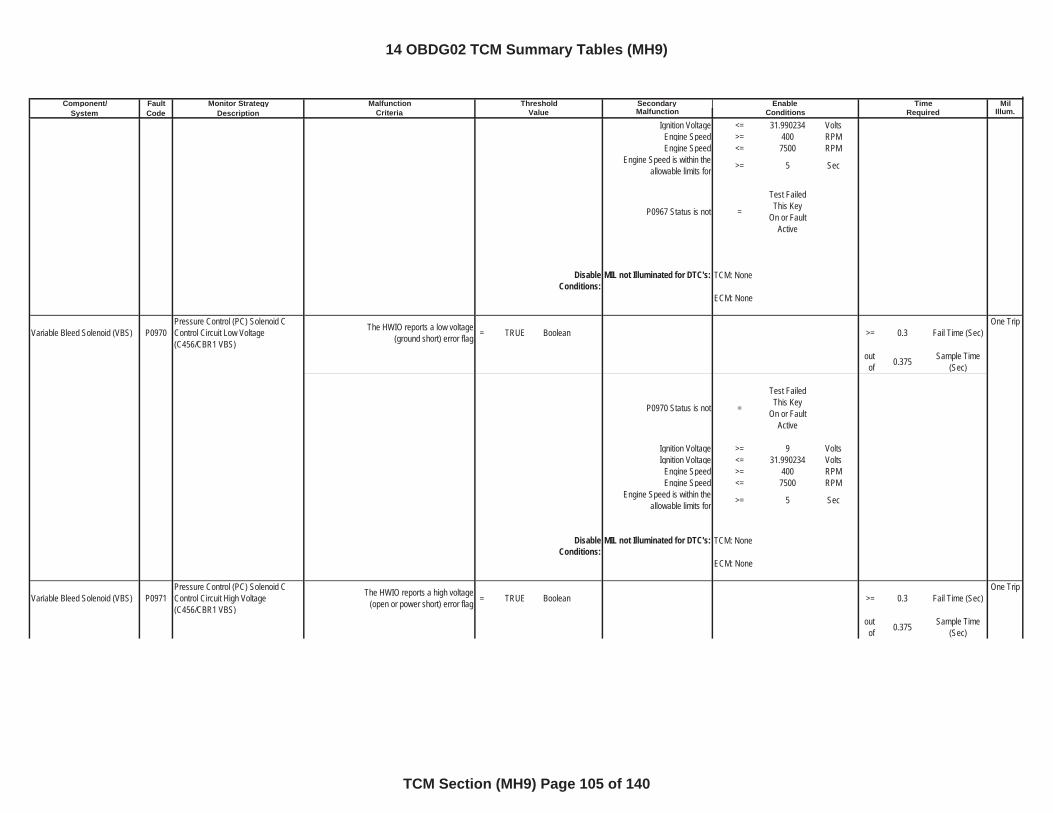
Component/ Fault Monitor Strategy Secondary MilSystem Code Description Malfunction Illum.
Malfunction Threshold Enable TimeCriteria Value Conditions Required
Ignition Voltage <= 31.990234 VoltsEngine Speed >= 400 RPMEngine Speed <= 7500 RPM
Engine Speed is within the allowable limits for >= 5 Sec
P0967 Status is not =
Test Failed This Key
On or Fault Active
DisableConditions:
MIL not Illuminated for DTC's:
Variable Bleed Solenoid (VBS) P0970Pressure Control (PC) Solenoid C Control Circuit Low Voltage(C456/CBR1 VBS)
The HWIO reports a low voltage (ground short) error flag = TRUE Boolean >= 0.3 Fail Time (Sec)
One Trip
outof 0.375 Sample Time
(Sec)
P0970 Status is not =
Test Failed This Key
On or Fault Active
Ignition Voltage >= 9 VoltsIgnition Voltage <= 31.990234 Volts
Engine Speed >= 400 RPMEngine Speed <= 7500 RPM
Engine Speed is within the allowable limits for >= 5 Sec
DisableConditions:
MIL not Illuminated for DTC's:
Variable Bleed Solenoid (VBS) P0971Pressure Control (PC) Solenoid C Control Circuit High Voltage(C456/CBR1 VBS)
The HWIO reports a high voltage (open or power short) error flag = TRUE Boolean >= 0.3 Fail Time (Sec)
One Trip
outof 0.375 Sample Time
(Sec)
TCM: None
ECM: None
TCM: None
ECM: None
14 OBDG02 TCM Summary Tables (MH9)
TCM Section (MH9) Page 105 of 140
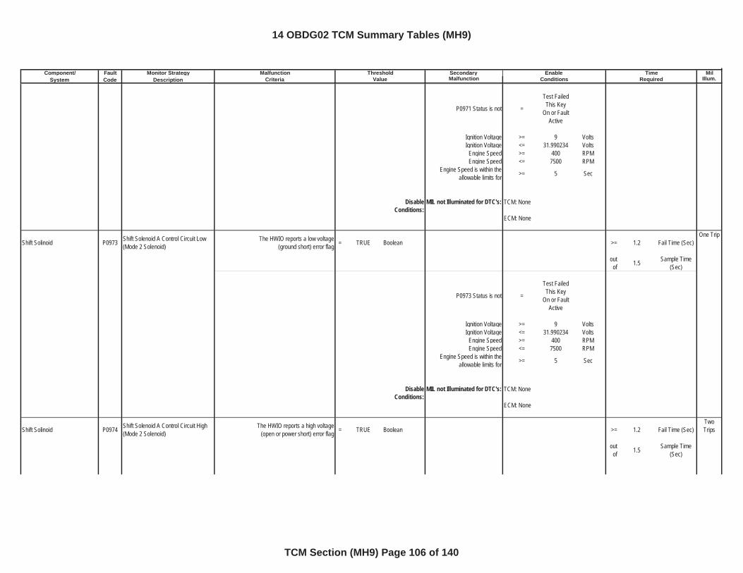
Component/ Fault Monitor Strategy Secondary MilSystem Code Description Malfunction Illum.
Malfunction Threshold Enable TimeCriteria Value Conditions Required
P0971 Status is not =
Test Failed This Key
On or Fault Active
Ignition Voltage >= 9 VoltsIgnition Voltage <= 31.990234 Volts
Engine Speed >= 400 RPMEngine Speed <= 7500 RPM
Engine Speed is within the allowable limits for >= 5 Sec
DisableConditions:
MIL not Illuminated for DTC's:
Shift Solinoid P0973 Shift Solenoid A Control Circuit Low(Mode 2 Solenoid)
The HWIO reports a low voltage (ground short) error flag = TRUE Boolean >= 1.2 Fail Time (Sec)
One Trip
outof 1.5 Sample Time
(Sec)
P0973 Status is not =
Test Failed This Key
On or Fault Active
Ignition Voltage >= 9 VoltsIgnition Voltage <= 31.990234 Volts
Engine Speed >= 400 RPMEngine Speed <= 7500 RPM
Engine Speed is within the allowable limits for >= 5 Sec
DisableConditions:
MIL not Illuminated for DTC's:
Shift Solinoid P0974 Shift Solenoid A Control Circuit High(Mode 2 Solenoid)
The HWIO reports a high voltage (open or power short) error flag = TRUE Boolean >= 1.2 Fail Time (Sec)
TwoTrips
outof 1.5 Sample Time
(Sec)
TCM: None
ECM: None
TCM: None
ECM: None
14 OBDG02 TCM Summary Tables (MH9)
TCM Section (MH9) Page 106 of 140
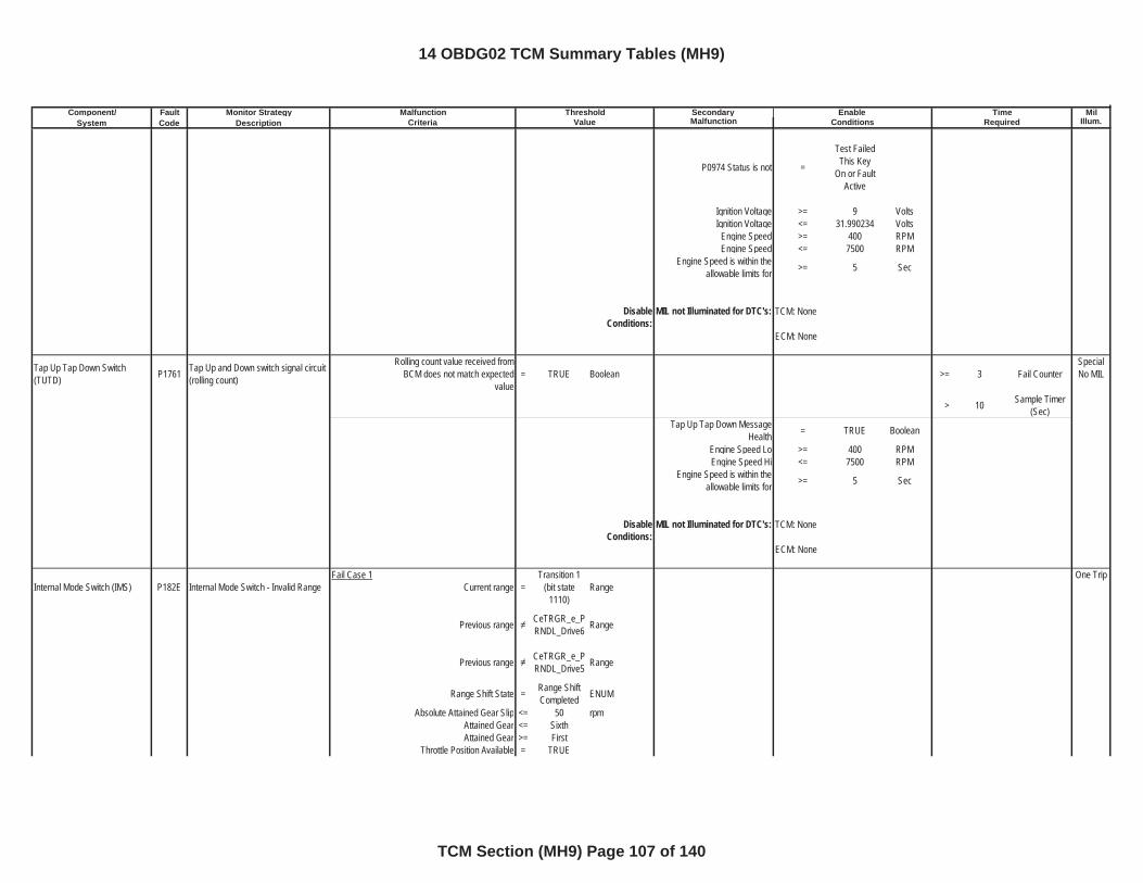
Component/ Fault Monitor Strategy Secondary MilSystem Code Description Malfunction Illum.
Malfunction Threshold Enable TimeCriteria Value Conditions Required
P0974 Status is not =
Test Failed This Key
On or Fault Active
Ignition Voltage >= 9 VoltsIgnition Voltage <= 31.990234 Volts
Engine Speed >= 400 RPMEngine Speed <= 7500 RPM
Engine Speed is within the allowable limits for >= 5 Sec
DisableConditions:
MIL not Illuminated for DTC's:
Tap Up Tap Down Switch (TUTD) P1761 Tap Up and Down switch signal circuit
(rolling count)
Rolling count value received from BCM does not match expected
value= TRUE Boolean >= 3 Fail Counter
Special No MIL
> 10 Sample Timer (Sec)
Tap Up Tap Down Message Health = TRUE Boolean
Engine Speed Lo >= 400 RPMEngine Speed Hi <= 7500 RPM
Engine Speed is within the allowable limits for >= 5 Sec
DisableConditions:
MIL not Illuminated for DTC's:
Internal Mode Switch (IMS) P182E Internal Mode Switch - Invalid RangeFail Case 1
Current range =Transition 1
(bit state 1110)
RangeOne Trip
Previous range CeTRGR_e_PRNDL_Drive6 Range
Previous range CeTRGR_e_PRNDL_Drive5 Range
Range Shift State = Range Shift Completed ENUM
Absolute Attained Gear Slip <= 50 rpmAttained Gear <= SixthAttained Gear >= First
Throttle Position Available = TRUE
TCM: None
ECM: None
TCM: None
ECM: None
14 OBDG02 TCM Summary Tables (MH9)
TCM Section (MH9) Page 107 of 140
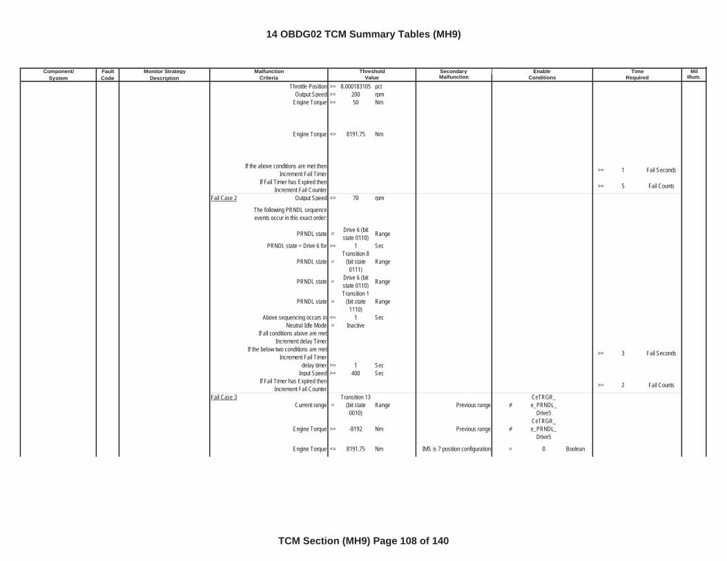
Component/ Fault Monitor Strategy Secondary MilSystem Code Description Malfunction Illum.
Malfunction Threshold Enable TimeCriteria Value Conditions Required
Throttle Position >= 8.000183105 pctOutput Speed >= 200 rpm
Engine Torque >= 50 Nm
Engine Torque <= 8191.75 Nm
If the above conditions are met then Increment Fail Timer >= 1 Fail Seconds
If Fail Timer has Expired then Increment Fail Counter >= 5 Fail Counts
Fail Case 2 Output Speed <= 70 rpm
The following PRNDL sequence events occur in this exact order:
PRNDL state = Drive 6 (bit state 0110) Range
PRNDL state = Drive 6 for >= 1 Sec
PRNDL state =Transition 8
(bit state 0111)
Range
PRNDL state = Drive 6 (bit state 0110) Range
PRNDL state =Transition 1
(bit state 1110)
Range
Above sequencing occurs in <= 1 SecNeutral Idle Mode = Inactive
If all conditions above are met Increment delay Timer
If the below two conditions are met Increment Fail Timer >= 3 Fail Seconds
delay timer >= 1 SecInput Speed >= 400 Sec
If Fail Timer has Expired then Increment Fail Counter >= 2 Fail Counts
Fail Case 3Current range =
Transition 13 (bit state
0010)Range Previous range
CeTRGR_e_PRNDL_
Drive5
Engine Torque >= -8192 Nm Previous rangeCeTRGR_e_PRNDL_
Drive5
Engine Torque <= 8191.75 Nm IMS is 7 position configuration = 0 Boolean
14 OBDG02 TCM Summary Tables (MH9)
TCM Section (MH9) Page 108 of 140
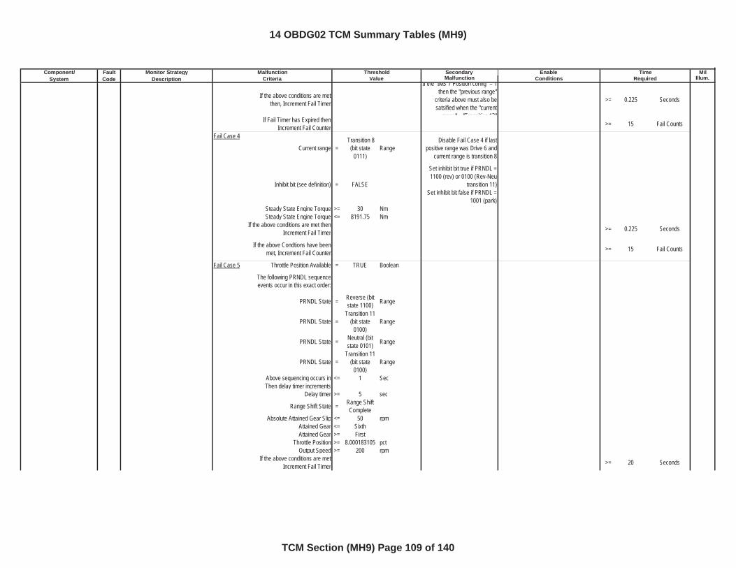
Component/ Fault Monitor Strategy Secondary MilSystem Code Description Malfunction Illum.
Malfunction Threshold Enable TimeCriteria Value Conditions Required
If the above conditions are met then, Increment Fail Timer
If the IMS 7 Position config = 1 then the "previous range"
criteria above must also be satsified when the "current
range" = "Transition 13"
>= 0.225 Seconds
If Fail Timer has Expired then Increment Fail Counter >= 15 Fail Counts
Fail Case 4
Current range = Transition 8
(bit state 0111)
RangeDisable Fail Case 4 if last
positive range was Drive 6 and current range is transition 8
Inhibit bit (see definition) = FALSE
Set inhibit bit true if PRNDL = 1100 (rev) or 0100 (Rev-Neu
transition 11)Set inhibit bit false if PRNDL =
1001 (park)Steady State Engine Torque >= 30 NmSteady State Engine Torque <= 8191.75 Nm
If the above conditions are met then Increment Fail Timer >= 0.225 Seconds
If the above Condtions have been met, Increment Fail Counter >= 15 Fail Counts
Fail Case 5 Throttle Position Available = TRUE Boolean
The following PRNDL sequence events occur in this exact order:
PRNDL State = Reverse (bit state 1100) Range
PRNDL State =Transition 11
(bit state 0100)
Range
PRNDL State = Neutral (bit state 0101) Range
PRNDL State =Transition 11
(bit state 0100)
Range
Above sequencing occurs in <= 1 SecThen delay timer increments
Delay timer >= 5 sec
Range Shift State = Range Shift Complete
Absolute Attained Gear Slip <= 50 rpmAttained Gear <= SixthAttained Gear >= First
Throttle Position >= 8.000183105 pctOutput Speed >= 200 rpm
If the above conditions are met Increment Fail Timer >= 20 Seconds
14 OBDG02 TCM Summary Tables (MH9)
TCM Section (MH9) Page 109 of 140
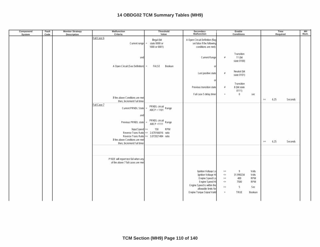
Component/ Fault Monitor Strategy Secondary MilSystem Code Description Malfunction Illum.
Malfunction Threshold Enable TimeCriteria Value Conditions Required
Fail Case 6
Current range = Illegal (bit
state 0000 or 1000 or 0001)
A Open Circuit Definition (flag set false if the following
conditions are met):
and Current RangeTransition
11 (bit state 0100)
A Open Circuit (See Definition) = FALSE Boolean or
Last positive state Neutral (bit state 0101)
or
Previous transition state Transition 8 (bit state
0111)Fail case 5 delay timer = 0 sec
If the above Condtions are met then, Increment Fail timer >= 6.25 Seconds
Fail Case 7Current PRNDL State = PRNDL circuit
ABCP = 1101 Range
and
Previous PRNDL state = PRNDL circuit ABCP =1111 Range
Input Speed >= 150 RPMReverse Trans Ratio <= 2.670166016 ratioReverse Trans Ratio >= 3.072021484 ratio
If the above Condtions are met then, Increment Fail timer >= 6.25 Seconds
P182E will report test fail when any of the above 7 fail cases are met
Ignition Voltage Lo >= 9 VoltsIgnition Voltage Hi <= 31.990234 VoltsEngine Speed Lo >= 400 RPMEngine Speed Hi <= 7500 RPM
Engine Speed is within the allowable limits for >= 5 Sec
Engine Torque Signal Valid = TRUE Boolean
14 OBDG02 TCM Summary Tables (MH9)
TCM Section (MH9) Page 110 of 140
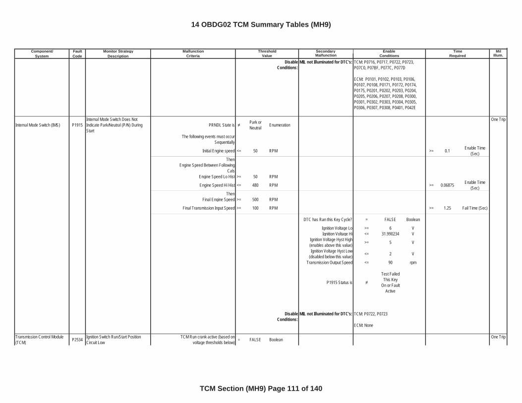
Component/ Fault Monitor Strategy Secondary MilSystem Code Description Malfunction Illum.
Malfunction Threshold Enable TimeCriteria Value Conditions Required
DisableConditions:
MIL not Illuminated for DTC's:
Internal Mode Switch (IMS) P1915Internal Mode Switch Does Not Indicate Park/Neutral (P/N) During Start
PRNDL State is Park or Neutral Enumeration
One Trip
The following events must occur Sequentially
Initial Engine speed <= 50 RPM >= 0.1 Enable Time (Sec)
ThenEngine Speed Between Following
Cals Engine Speed Lo Hist >= 50 RPM
Engine Speed Hi Hist <= 480 RPM >= 0.06875 Enable Time (Sec)
ThenFinal Engine Speed >= 500 RPM
Final Transmission Input Speed >= 100 RPM >= 1.25 Fail Time (Sec)
DTC has Ran this Key Cycle? = FALSE Boolean
Ignition Voltage Lo >= 6 VIgnition Voltage Hi <= 31.990234 V
Ignition Voltage Hyst High (enables above this value) >= 5 V
Ignition Voltage Hyst Low (disabled below this value) <= 2 V
Transmission Output Speed <= 90 rpm
P1915 Status is
Test Failed This Key
On or Fault Active
DisableConditions:
MIL not Illuminated for DTC's:
Transmission Control Module (TCM) P2534 Ignition Switch Run/Start Position
Circuit LowTCM Run crank active (based on
voltage thresholds below) = FALSE Boolean One Trip
TCM: P0716, P0717, P0722, P0723, P07C0, P07BF, P077C, P077D
ECM: P0101, P0102, P0103, P0106, P0107, P0108, P0171, P0172, P0174, P0175, P0201, P0202, P0203, P0204, P0205, P0206, P0207, P0208, P0300, P0301, P0302, P0303, P0304, P0305, P0306, P0307, P0308, P0401, P042E
TCM: P0722, P0723
ECM: None
14 OBDG02 TCM Summary Tables (MH9)
TCM Section (MH9) Page 111 of 140
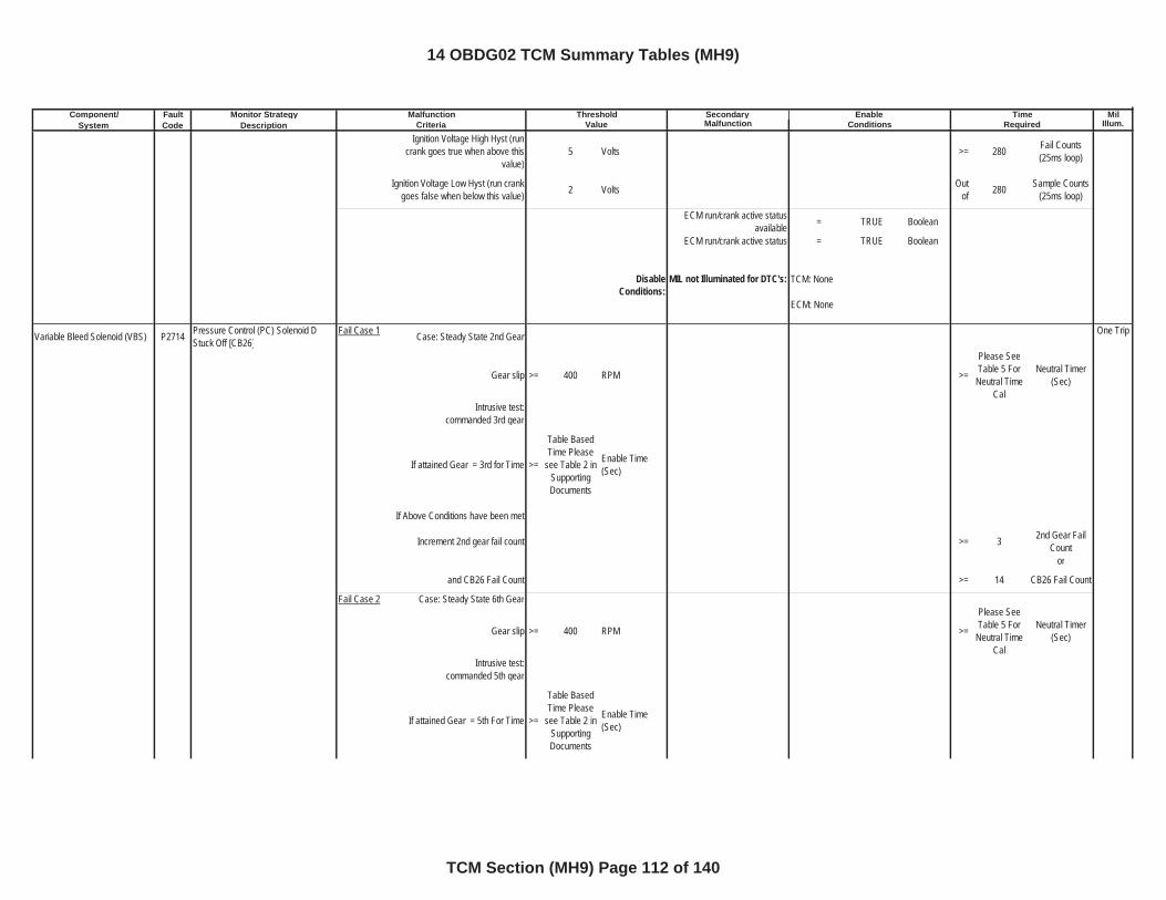
Component/ Fault Monitor Strategy Secondary MilSystem Code Description Malfunction Illum.
Malfunction Threshold Enable TimeCriteria Value Conditions Required
Ignition Voltage High Hyst (run crank goes true when above this
value)5 Volts >= 280 Fail Counts
(25ms loop)
Ignition Voltage Low Hyst (run crank goes false when below this value) 2 Volts Out
of 280 Sample Counts (25ms loop)
ECM run/crank active status available = TRUE Boolean
ECM run/crank active status = TRUE Boolean
DisableConditions:
MIL not Illuminated for DTC's:
Variable Bleed Solenoid (VBS) P2714 Pressure Control (PC) Solenoid D Stuck Off [CB26]
Fail Case 1 Case: Steady State 2nd Gear One Trip
Gear slip >= 400 RPM >=
Please See Table 5 For
Neutral Time Cal
Neutral Timer (Sec)
Intrusive test:commanded 3rd gear
If attained Gear = 3rd for Time >=
Table Based Time Please
see Table 2 in SupportingDocuments
Enable Time (Sec)
If Above Conditions have been met
Increment 2nd gear fail count >= 3 2nd Gear Fail Count
or
and CB26 Fail Count >= 14 CB26 Fail Count
Fail Case 2 Case: Steady State 6th Gear
Gear slip >= 400 RPM >=
Please See Table 5 For
Neutral Time Cal
Neutral Timer (Sec)
Intrusive test:commanded 5th gear
If attained Gear = 5th For Time >=
Table Based Time Please
see Table 2 in SupportingDocuments
Enable Time (Sec)
TCM: None
ECM: None
14 OBDG02 TCM Summary Tables (MH9)
TCM Section (MH9) Page 112 of 140
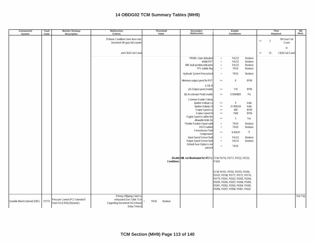
Component/ Fault Monitor Strategy Secondary MilSystem Code Description Malfunction Illum.
Malfunction Threshold Enable TimeCriteria Value Conditions Required
If Above Conditions have been met, Increment 5th gear fail counter >= 3 5th Gear Fail
Count
or
and CB26 Fail Count >= 14 CB26 Fail Count
PRNDL State defaulted = FALSE Booleaninhibit RVT = FALSE Boolean
IMS fault pending indication = FALSE BooleanTPS validity flag = TRUE Boolean
Hydraulic System Pressurized = TRUE Boolean
Minimum output speed for RVT >= 0 RPM
A OR B(A) Output speed enable >= 110 RPM
(B) Accelerator Pedal enable >= 0.5004883 Pct
Common Enable CriteriaIgnition Voltage Lo >= 9 VoltsIgnition Voltage Hi <= 31.990234 VoltsEngine Speed Lo >= 400 RPMEngine Speed Hi <= 7500 RPM
Engine Speed is within the allowable limits for >= 5 Sec
Throttle Position Signal valid = TRUE BooleanHSD Enabled = TRUE Boolean
Transmission Fluid Temperature >= -6.65625 ºC
Input Speed Sensor fault = FALSE BooleanOutput Speed Sensor fault = FALSE BooleanDefault Gear Option is not
present = TRUE
DisableConditions:
MIL not Illuminated for DTC's:
Variable Bleed Solenoid (VBS) P2715 Pressure Control (PC) Solenoid D Stuck On [CB26] (Dynamic)
Primary Offgoing Clutch is exhausted (See Table 13 in
Supporting Documents for Exhaust Delay Timers)
= TRUE Boolean
One Trip
TCM: P0716, P0717, P0722, P0723, P182E
ECM: P0101, P0102, P0103, P0106, P0107, P0108, P0171, P0172, P0174, P0175, P0201, P0202, P0203, P0204, P0205, P0206, P0207, P0208, P0300, P0301, P0302, P0303, P0304, P0305, P0306, P0307, P0308, P0401, P042E
14 OBDG02 TCM Summary Tables (MH9)
TCM Section (MH9) Page 113 of 140
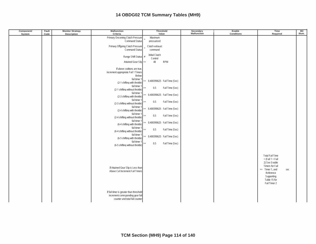
Component/ Fault Monitor Strategy Secondary MilSystem Code Description Malfunction Illum.
Malfunction Threshold Enable TimeCriteria Value Conditions Required
Primary Oncoming Clutch Pressure Command Status = Maximum
pressurized
Primary Offgoing Clutch Pressure Command Status = Clutch exhaust
command
Range Shift Status Initial Clutch Control
Attained Gear Slip <= 40 RPM
If above coditons are true, increment appropriate Fail 1 Timers
Below:fail timer 1
(2-1 shifting with throttle) >= 0.400390625 Fail Time (Sec)
fail timer 1(2-1 shifting without throttle) >= 0.5 Fail Time (Sec)
fail timer 1(2-3 shifting with throttle) >= 0.400390625 Fail Time (Sec)
fail timer 1(2-3 shifting without throttle) >= 0.5 Fail Time (Sec)
fail timer 1(2-4 shifting with throttle) >= 0.400390625 Fail Time (Sec)
fail timer 1(2-4 shifting without throttle) >= 0.5 Fail Time (Sec)
fail timer 1(6-4 shifting with throttle) >= 0.400390625 Fail Time (Sec)
fail timer 1(6-4 shifting without throttle) >= 0.5 Fail Time (Sec)
fail timer 1(6-5 shifting with throttle) >= 0.400390625 Fail Time (Sec)
fail timer 1(6-5 shifting without throttle) >= 0.5 Fail Time (Sec)
If Attained Gear Slip is Less than Above Cal Increment Fail Timers >=
Total Fail Time = (Fail 1 + Fail 2) See Enable Timers for Fail Timer 1, and ReferenceSupportingTable 15 for Fail Timer 2
sec
If fail timer is greater than threshold increment corresponding gear fail
counter and total fail counter
14 OBDG02 TCM Summary Tables (MH9)
TCM Section (MH9) Page 114 of 140
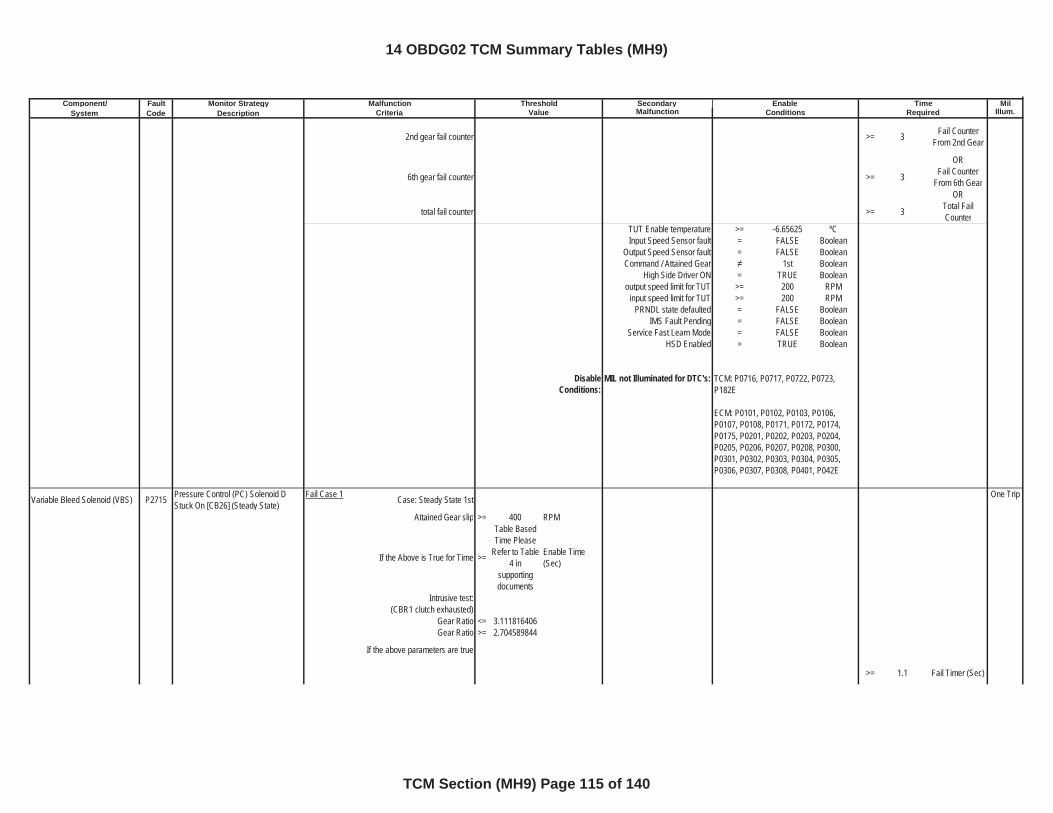
Component/ Fault Monitor Strategy Secondary MilSystem Code Description Malfunction Illum.
Malfunction Threshold Enable TimeCriteria Value Conditions Required
2nd gear fail counter >= 3 Fail Counter From 2nd Gear
OR
6th gear fail counter >= 3 Fail Counter From 6th Gear
OR
total fail counter >= 3 Total Fail Counter
TUT Enable temperature >= -6.65625 ºCInput Speed Sensor fault = FALSE Boolean
Output Speed Sensor fault = FALSE BooleanCommand / Attained Gear 1st Boolean
High Side Driver ON = TRUE Booleanoutput speed limit for TUT >= 200 RPM
input speed limit for TUT >= 200 RPMPRNDL state defaulted = FALSE Boolean
IMS Fault Pending = FALSE BooleanService Fast Learn Mode = FALSE Boolean
HSD Enabled = TRUE Boolean
DisableConditions:
MIL not Illuminated for DTC's:
Variable Bleed Solenoid (VBS) P2715 Pressure Control (PC) Solenoid D Stuck On [CB26] (Steady State)
Fail Case 1 Case: Steady State 1st One Trip
Attained Gear slip >= 400 RPM
If the Above is True for Time >=
Table Based Time Please
Refer to Table 4 in
supportingdocuments
Enable Time (Sec)
Intrusive test:(CBR1 clutch exhausted)
Gear Ratio <= 3.111816406Gear Ratio >= 2.704589844
If the above parameters are true
>= 1.1 Fail Timer (Sec)
TCM: P0716, P0717, P0722, P0723, P182E
ECM: P0101, P0102, P0103, P0106, P0107, P0108, P0171, P0172, P0174, P0175, P0201, P0202, P0203, P0204, P0205, P0206, P0207, P0208, P0300, P0301, P0302, P0303, P0304, P0305, P0306, P0307, P0308, P0401, P042E
14 OBDG02 TCM Summary Tables (MH9)
TCM Section (MH9) Page 115 of 140
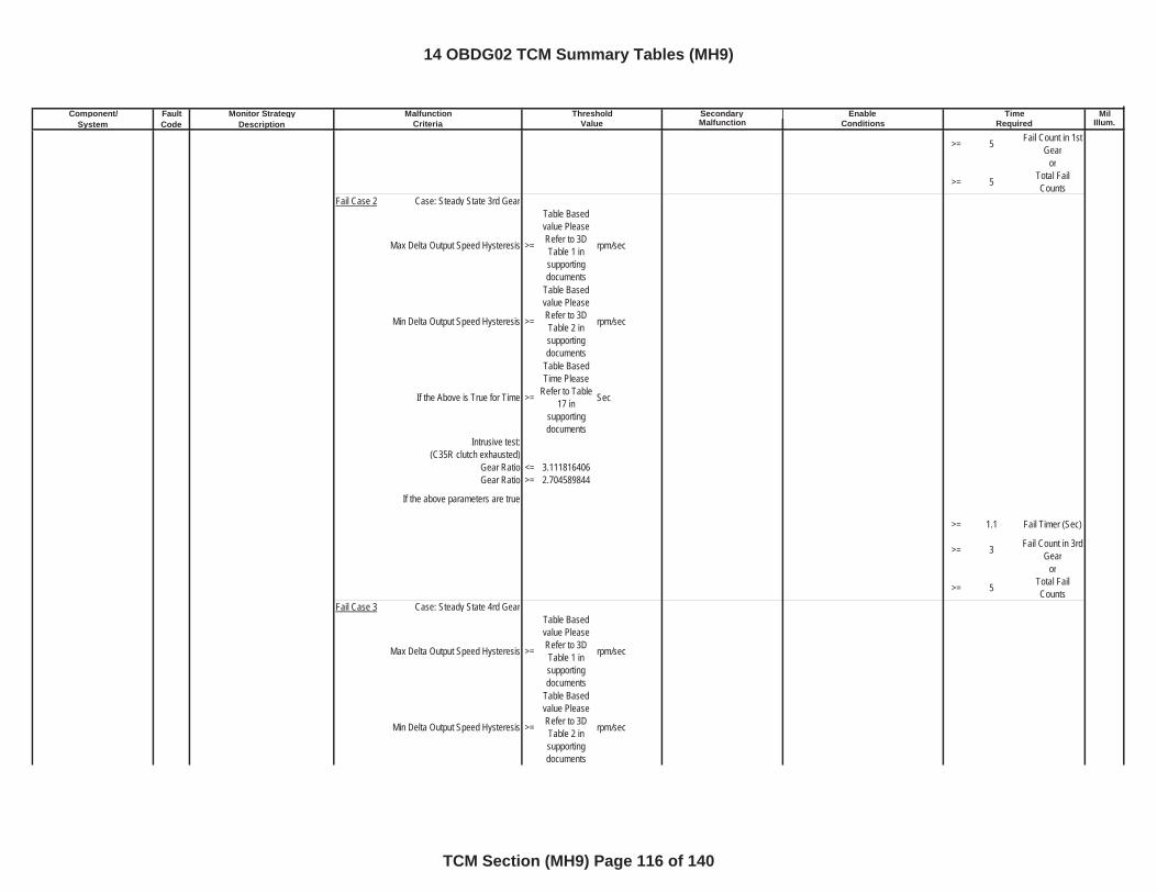
Component/ Fault Monitor Strategy Secondary MilSystem Code Description Malfunction Illum.
Malfunction Threshold Enable TimeCriteria Value Conditions Required
>= 5 Fail Count in 1st Gear
or
>= 5 Total Fail Counts
Fail Case 2 Case: Steady State 3rd Gear
Max Delta Output Speed Hysteresis >=
Table Based value Please Refer to 3D Table 1 in supportingdocuments
rpm/sec
Min Delta Output Speed Hysteresis >=
Table Based value Please Refer to 3D Table 2 in supportingdocuments
rpm/sec
If the Above is True for Time >=
Table Based Time Please
Refer to Table 17 in
supportingdocuments
Sec
Intrusive test: (C35R clutch exhausted)
Gear Ratio <= 3.111816406Gear Ratio >= 2.704589844
If the above parameters are true
>= 1.1 Fail Timer (Sec)
>= 3 Fail Count in 3rd Gear
or
>= 5 Total Fail Counts
Fail Case 3 Case: Steady State 4rd Gear
Max Delta Output Speed Hysteresis >=
Table Based value Please Refer to 3D Table 1 in supportingdocuments
rpm/sec
Min Delta Output Speed Hysteresis >=
Table Based value Please Refer to 3D Table 2 in supportingdocuments
rpm/sec
14 OBDG02 TCM Summary Tables (MH9)
TCM Section (MH9) Page 116 of 140
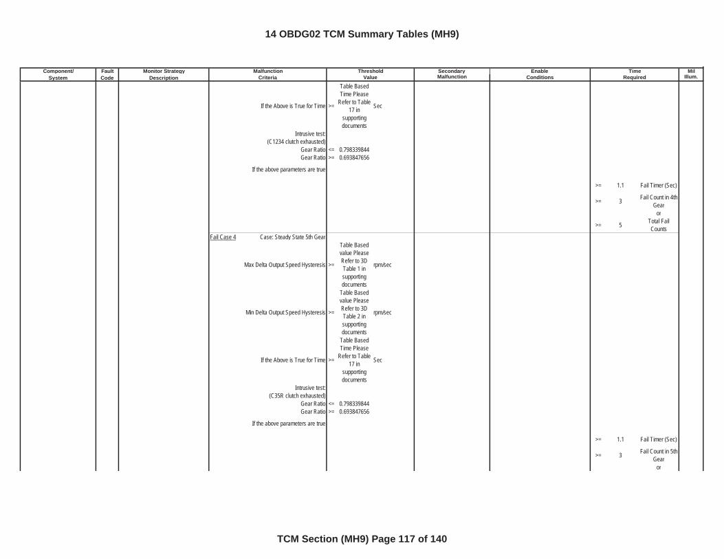
Component/ Fault Monitor Strategy Secondary MilSystem Code Description Malfunction Illum.
Malfunction Threshold Enable TimeCriteria Value Conditions Required
If the Above is True for Time >=
Table Based Time Please
Refer to Table 17 in
supportingdocuments
Sec
Intrusive test: (C1234 clutch exhausted)
Gear Ratio <= 0.798339844Gear Ratio >= 0.693847656
If the above parameters are true
>= 1.1 Fail Timer (Sec)
>= 3 Fail Count in 4th Gear
or
>= 5 Total Fail Counts
Fail Case 4 Case: Steady State 5th Gear
Max Delta Output Speed Hysteresis >=
Table Based value Please Refer to 3D Table 1 in supportingdocuments
rpm/sec
Min Delta Output Speed Hysteresis >=
Table Based value Please Refer to 3D Table 2 in supportingdocuments
rpm/sec
If the Above is True for Time >=
Table Based Time Please
Refer to Table 17 in
supportingdocuments
Sec
Intrusive test: (C35R clutch exhausted)
Gear Ratio <= 0.798339844Gear Ratio >= 0.693847656
If the above parameters are true
>= 1.1 Fail Timer (Sec)
>= 3 Fail Count in 5th Gear
or
14 OBDG02 TCM Summary Tables (MH9)
TCM Section (MH9) Page 117 of 140
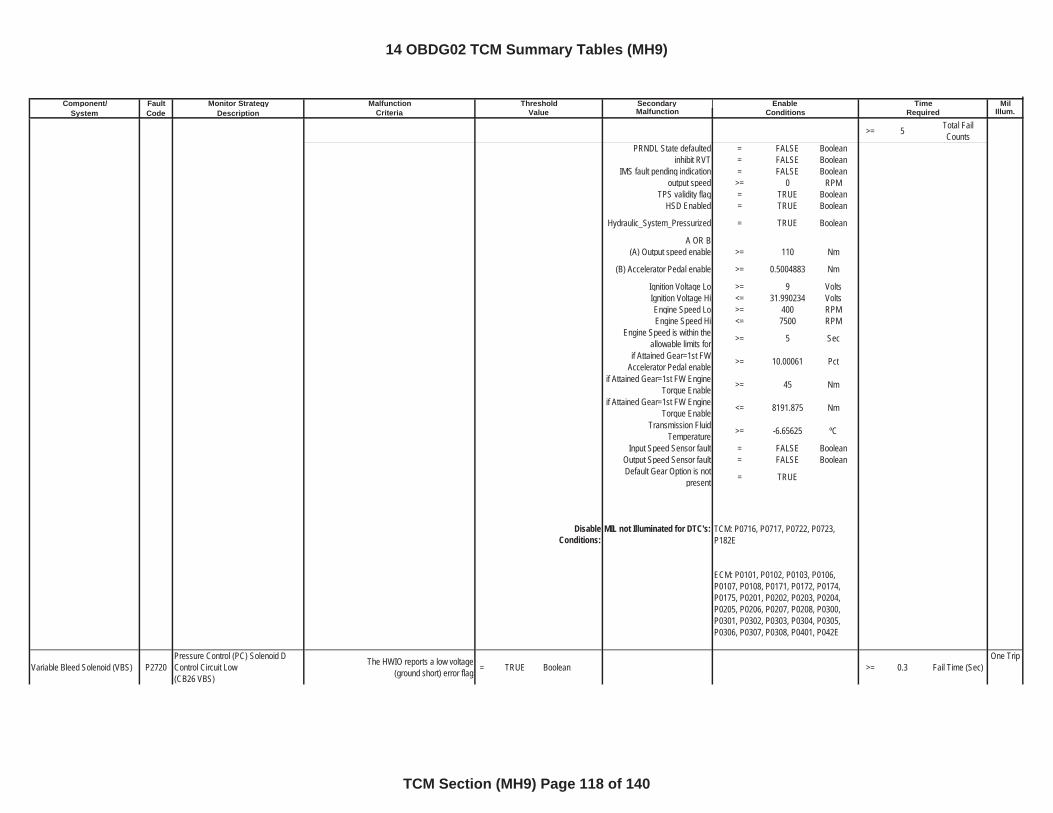
Component/ Fault Monitor Strategy Secondary MilSystem Code Description Malfunction Illum.
Malfunction Threshold Enable TimeCriteria Value Conditions Required
>= 5 Total Fail Counts
PRNDL State defaulted = FALSE Booleaninhibit RVT = FALSE Boolean
IMS fault pending indication = FALSE Booleanoutput speed >= 0 RPM
TPS validity flag = TRUE BooleanHSD Enabled = TRUE Boolean
Hydraulic_System_Pressurized = TRUE Boolean
A OR B(A) Output speed enable >= 110 Nm
(B) Accelerator Pedal enable >= 0.5004883 Nm
Ignition Voltage Lo >= 9 VoltsIgnition Voltage Hi <= 31.990234 VoltsEngine Speed Lo >= 400 RPMEngine Speed Hi <= 7500 RPM
Engine Speed is within the allowable limits for >= 5 Sec
if Attained Gear=1st FW Accelerator Pedal enable >= 10.00061 Pct
if Attained Gear=1st FW Engine Torque Enable >= 45 Nm
if Attained Gear=1st FW Engine Torque Enable <= 8191.875 Nm
Transmission Fluid Temperature >= -6.65625 ºC
Input Speed Sensor fault = FALSE BooleanOutput Speed Sensor fault = FALSE BooleanDefault Gear Option is not
present = TRUE
DisableConditions:
MIL not Illuminated for DTC's:
Variable Bleed Solenoid (VBS) P2720Pressure Control (PC) Solenoid D Control Circuit Low(CB26 VBS)
The HWIO reports a low voltage (ground short) error flag = TRUE Boolean >= 0.3 Fail Time (Sec)
One Trip
TCM: P0716, P0717, P0722, P0723, P182E
ECM: P0101, P0102, P0103, P0106, P0107, P0108, P0171, P0172, P0174, P0175, P0201, P0202, P0203, P0204, P0205, P0206, P0207, P0208, P0300, P0301, P0302, P0303, P0304, P0305, P0306, P0307, P0308, P0401, P042E
14 OBDG02 TCM Summary Tables (MH9)
TCM Section (MH9) Page 118 of 140
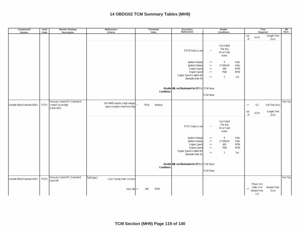
Component/ Fault Monitor Strategy Secondary MilSystem Code Description Malfunction Illum.
Malfunction Threshold Enable TimeCriteria Value Conditions Required
outof 0.375 Sample Time
(Sec)
P2770 Status is not =
Test Failed This Key
On or Fault Active
Ignition Voltage >= 9 VoltsIgnition Voltage <= 31.990234 Volts
Engine Speed >= 400 RPMEngine Speed <= 7500 RPM
Engine Speed is within the allowable limits for >= 5 Sec
DisableConditions:
MIL not Illuminated for DTC's:
Variable Bleed Solenoid (VBS) P2721Pressure Control (PC) Solenoid D Control Circuit High(CB26 VBS)
The HWIO reports a high voltage (open or power short) error flag = TRUE Boolean >= 0.3 Fail Time (Sec)
One Trip
outof 0.375 Sample Time
(Sec)
P2721 Status is not =
Test Failed This Key
On or Fault Active
Ignition Voltage >= 9 VoltsIgnition Voltage <= 31.990234 Volts
Engine Speed >= 400 RPMEngine Speed <= 7500 RPM
Engine Speed is within the allowable limits for >= 5 Sec
DisableConditions:
MIL not Illuminated for DTC's:
Variable Bleed Solenoid (VBS) P2723 Pressure Control (PC) Solenoid E Stuck Off
Fail Case 1 Case: Steady State 1st Gear One Trip
Gear slip >= 400 RPM >=
Please See Table 5 For
Neutral Time Cal
Neutral Timer (Sec)
TCM: None
ECM: None
TCM: None
ECM: None
14 OBDG02 TCM Summary Tables (MH9)
TCM Section (MH9) Page 119 of 140
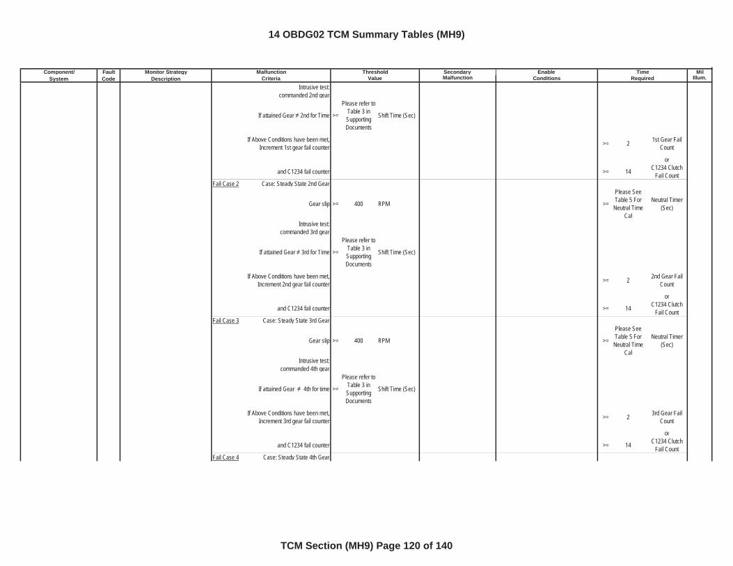
Component/ Fault Monitor Strategy Secondary MilSystem Code Description Malfunction Illum.
Malfunction Threshold Enable TimeCriteria Value Conditions Required
Intrusive test:commanded 2nd gear
If attained Gear 2nd for Time >=
Please refer to Table 3 in SupportingDocuments
Shift Time (Sec)
If Above Conditions have been met, Increment 1st gear fail counter >= 2 1st Gear Fail
Count
or
and C1234 fail counter >= 14 C1234 Clutch Fail Count
Fail Case 2 Case: Steady State 2nd Gear
Gear slip >= 400 RPM >=
Please See Table 5 For
Neutral Time Cal
Neutral Timer (Sec)
Intrusive test:commanded 3rd gear
If attained Gear 3rd for Time >=
Please refer to Table 3 in SupportingDocuments
Shift Time (Sec)
If Above Conditions have been met, Increment 2nd gear fail counter >= 2 2nd Gear Fail
Count
or
and C1234 fail counter >= 14 C1234 Clutch Fail Count
Fail Case 3 Case: Steady State 3rd Gear
Gear slip >= 400 RPM >=
Please See Table 5 For
Neutral Time Cal
Neutral Timer (Sec)
Intrusive test:commanded 4th gear
If attained Gear 4th for time >=
Please refer to Table 3 in SupportingDocuments
Shift Time (Sec)
If Above Conditions have been met, Increment 3rd gear fail counter >= 2 3rd Gear Fail
Count
or
and C1234 fail counter >= 14 C1234 Clutch Fail Count
Fail Case 4 Case: Steady State 4th Gear
14 OBDG02 TCM Summary Tables (MH9)
TCM Section (MH9) Page 120 of 140
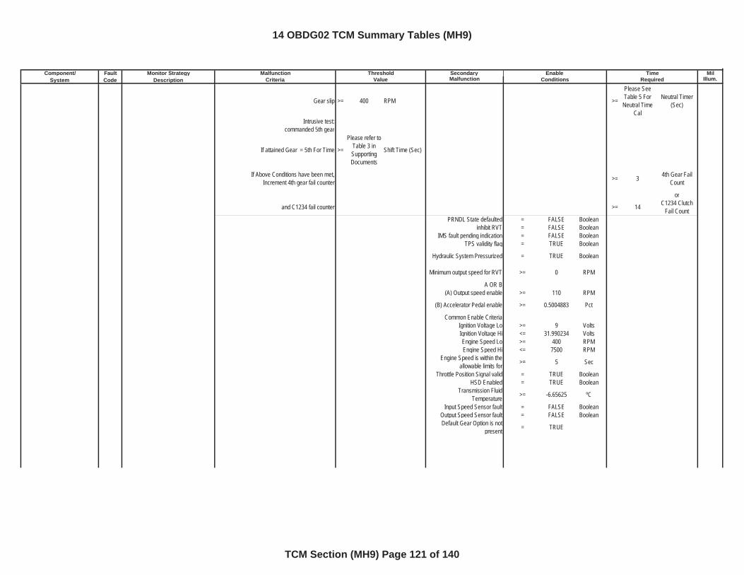
Component/ Fault Monitor Strategy Secondary MilSystem Code Description Malfunction Illum.
Malfunction Threshold Enable TimeCriteria Value Conditions Required
Gear slip >= 400 RPM >=
Please See Table 5 For
Neutral Time Cal
Neutral Timer (Sec)
Intrusive test:commanded 5th gear
If attained Gear = 5th For Time >=
Please refer to Table 3 in SupportingDocuments
Shift Time (Sec)
If Above Conditions have been met, Increment 4th gear fail counter >= 3 4th Gear Fail
Count
or
and C1234 fail counter >= 14 C1234 Clutch Fail Count
PRNDL State defaulted = FALSE Booleaninhibit RVT = FALSE Boolean
IMS fault pending indication = FALSE BooleanTPS validity flag = TRUE Boolean
Hydraulic System Pressurized = TRUE Boolean
Minimum output speed for RVT >= 0 RPM
A OR B(A) Output speed enable >= 110 RPM
(B) Accelerator Pedal enable >= 0.5004883 Pct
Common Enable CriteriaIgnition Voltage Lo >= 9 VoltsIgnition Voltage Hi <= 31.990234 VoltsEngine Speed Lo >= 400 RPMEngine Speed Hi <= 7500 RPM
Engine Speed is within the allowable limits for >= 5 Sec
Throttle Position Signal valid = TRUE BooleanHSD Enabled = TRUE Boolean
Transmission Fluid Temperature >= -6.65625 ºC
Input Speed Sensor fault = FALSE BooleanOutput Speed Sensor fault = FALSE BooleanDefault Gear Option is not
present = TRUE
14 OBDG02 TCM Summary Tables (MH9)
TCM Section (MH9) Page 121 of 140
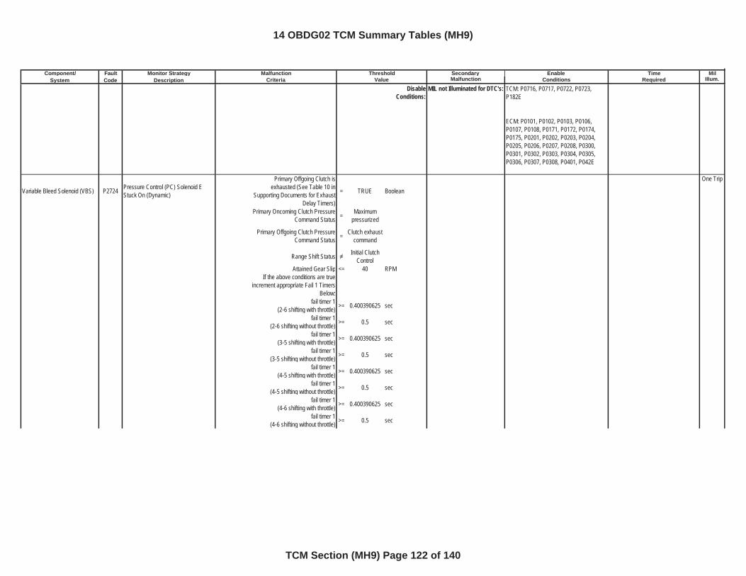
Component/ Fault Monitor Strategy Secondary MilSystem Code Description Malfunction Illum.
Malfunction Threshold Enable TimeCriteria Value Conditions Required
DisableConditions:
MIL not Illuminated for DTC's:
Variable Bleed Solenoid (VBS) P2724 Pressure Control (PC) Solenoid E Stuck On (Dynamic)
Primary Offgoing Clutch is exhausted (See Table 10 in
Supporting Documents for Exhaust Delay Timers)
= TRUE Boolean
One Trip
Primary Oncoming Clutch Pressure Command Status = Maximum
pressurized
Primary Offgoing Clutch Pressure Command Status = Clutch exhaust
command
Range Shift Status Initial Clutch Control
Attained Gear Slip <= 40 RPMIf the above conditions are true
increment appropriate Fail 1 Timers Below:
fail timer 1(2-6 shifting with throttle) >= 0.400390625 sec
fail timer 1(2-6 shifting without throttle) >= 0.5 sec
fail timer 1(3-5 shifting with throttle) >= 0.400390625 sec
fail timer 1(3-5 shifting without throttle) >= 0.5 sec
fail timer 1(4-5 shifting with throttle) >= 0.400390625 sec
fail timer 1(4-5 shifting without throttle) >= 0.5 sec
fail timer 1(4-6 shifting with throttle) >= 0.400390625 sec
fail timer 1(4-6 shifting without throttle) >= 0.5 sec
TCM: P0716, P0717, P0722, P0723, P182E
ECM: P0101, P0102, P0103, P0106, P0107, P0108, P0171, P0172, P0174, P0175, P0201, P0202, P0203, P0204, P0205, P0206, P0207, P0208, P0300, P0301, P0302, P0303, P0304, P0305, P0306, P0307, P0308, P0401, P042E
14 OBDG02 TCM Summary Tables (MH9)
TCM Section (MH9) Page 122 of 140
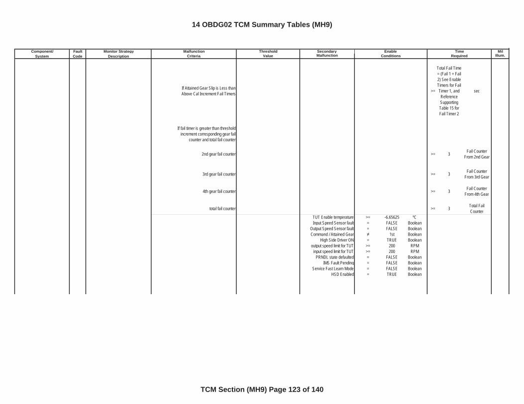
Component/ Fault Monitor Strategy Secondary MilSystem Code Description Malfunction Illum.
Malfunction Threshold Enable TimeCriteria Value Conditions Required
If Attained Gear Slip is Less than Above Cal Increment Fail Timers >=
Total Fail Time = (Fail 1 + Fail 2) See Enable Timers for Fail Timer 1, and ReferenceSupportingTable 15 for Fail Timer 2
sec
If fail timer is greater than threshold increment corresponding gear fail
counter and total fail counter
2nd gear fail counter >= 3 Fail Counter From 2nd Gear
3rd gear fail counter >= 3 Fail Counter From 3rd Gear
4th gear fail counter >= 3 Fail Counter From 4th Gear
total fail counter >= 3 Total Fail Counter
TUT Enable temperature >= -6.65625 ºCInput Speed Sensor fault = FALSE Boolean
Output Speed Sensor fault = FALSE BooleanCommand / Attained Gear 1st Boolean
High Side Driver ON = TRUE Booleanoutput speed limit for TUT >= 200 RPM
input speed limit for TUT >= 200 RPMPRNDL state defaulted = FALSE Boolean
IMS Fault Pending = FALSE BooleanService Fast Learn Mode = FALSE Boolean
HSD Enabled = TRUE Boolean
14 OBDG02 TCM Summary Tables (MH9)
TCM Section (MH9) Page 123 of 140
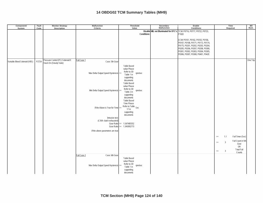
Component/ Fault Monitor Strategy Secondary MilSystem Code Description Malfunction Illum.
Malfunction Threshold Enable TimeCriteria Value Conditions Required
DisableConditions:
MIL not Illuminated for DTC's:
Variable Bleed Solenoid (VBS) P2724 Pressure Control (PC) Solenoid E Stuck On (Steady State)
Fail Case 1 Case: 5th Gear One Trip
Max Delta Output Speed Hysteresis >=
Table Based value Please Refer to 3D Table 1 in supportingdocuments
rpm/sec
Min Delta Output Speed Hysteresis >=
Table Based value Please Refer to 3D Table 2 in supportingdocuments
rpm/sec
If the Above is True for Time >=
Table Based Time Please
Refer to Table 17 in
supportingdocuments
Sec
Intrusive test:(C35R clutch exhausted)
Gear Ratio <= 1.547485352Gear Ratio >= 1.345092773
If the above parameters are true
>= 1.1 Fail Timer (Sec)
>= 3 Fail Count in 5th GearOR
>= 3 Total Fail Counts
Fail Case 2 Case: 6th Gear
Max Delta Output Speed Hysteresis >=
Table Based value Please Refer to 3D Table 1 in supportingdocuments
rpm/sec
TCM: P0716, P0717, P0722, P0723, P182E
ECM: P0101, P0102, P0103, P0106, P0107, P0108, P0171, P0172, P0174, P0175, P0201, P0202, P0203, P0204, P0205, P0206, P0207, P0208, P0300, P0301, P0302, P0303, P0304, P0305, P0306, P0307, P0308, P0401, P042E
14 OBDG02 TCM Summary Tables (MH9)
TCM Section (MH9) Page 124 of 140
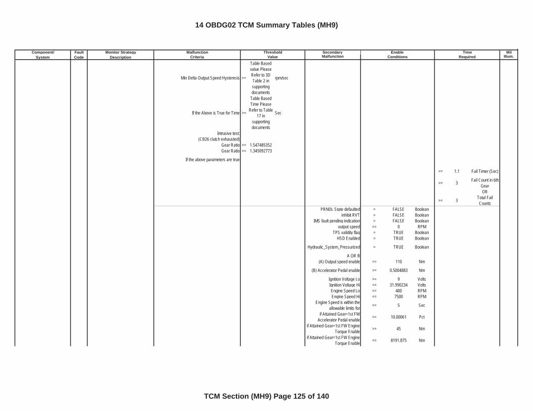
Component/ Fault Monitor Strategy Secondary MilSystem Code Description Malfunction Illum.
Malfunction Threshold Enable TimeCriteria Value Conditions Required
Min Delta Output Speed Hysteresis >=
Table Based value Please Refer to 3D Table 2 in supportingdocuments
rpm/sec
If the Above is True for Time >=
Table Based Time Please
Refer to Table 17 in
supportingdocuments
Sec
Intrusive test:(CB26 clutch exhausted)
Gear Ratio <= 1.547485352Gear Ratio >= 1.345092773
If the above parameters are true
>= 1.1 Fail Timer (Sec)
>= 3 Fail Count in 6th GearOR
>= 3 Total Fail Counts
PRNDL State defaulted = FALSE Booleaninhibit RVT = FALSE Boolean
IMS fault pending indication = FALSE Booleanoutput speed >= 0 RPM
TPS validity flag = TRUE BooleanHSD Enabled = TRUE Boolean
Hydraulic_System_Pressurized = TRUE Boolean
A OR B(A) Output speed enable >= 110 Nm
(B) Accelerator Pedal enable >= 0.5004883 Nm
Ignition Voltage Lo >= 9 VoltsIgnition Voltage Hi <= 31.990234 VoltsEngine Speed Lo >= 400 RPMEngine Speed Hi <= 7500 RPM
Engine Speed is within the allowable limits for >= 5 Sec
if Attained Gear=1st FW Accelerator Pedal enable >= 10.00061 Pct
if Attained Gear=1st FW Engine Torque Enable >= 45 Nm
if Attained Gear=1st FW Engine Torque Enable <= 8191.875 Nm
14 OBDG02 TCM Summary Tables (MH9)
TCM Section (MH9) Page 125 of 140
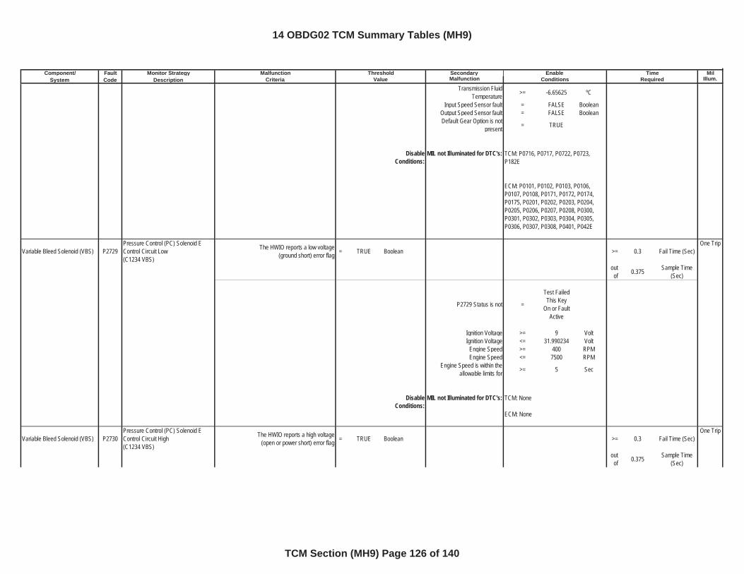
Component/ Fault Monitor Strategy Secondary MilSystem Code Description Malfunction Illum.
Malfunction Threshold Enable TimeCriteria Value Conditions Required
Transmission Fluid Temperature >= -6.65625 ºC
Input Speed Sensor fault = FALSE BooleanOutput Speed Sensor fault = FALSE BooleanDefault Gear Option is not
present = TRUE
DisableConditions:
MIL not Illuminated for DTC's:
Variable Bleed Solenoid (VBS) P2729Pressure Control (PC) Solenoid E Control Circuit Low(C1234 VBS)
The HWIO reports a low voltage (ground short) error flag = TRUE Boolean >= 0.3 Fail Time (Sec)
One Trip
outof 0.375 Sample Time
(Sec)
P2729 Status is not =
Test Failed This Key
On or Fault Active
Ignition Voltage >= 9 VoltIgnition Voltage <= 31.990234 Volt
Engine Speed >= 400 RPMEngine Speed <= 7500 RPM
Engine Speed is within the allowable limits for >= 5 Sec
DisableConditions:
MIL not Illuminated for DTC's:
Variable Bleed Solenoid (VBS) P2730Pressure Control (PC) Solenoid E Control Circuit High(C1234 VBS)
The HWIO reports a high voltage (open or power short) error flag = TRUE Boolean >= 0.3 Fail Time (Sec)
One Trip
outof 0.375 Sample Time
(Sec)
TCM: P0716, P0717, P0722, P0723, P182E
ECM: P0101, P0102, P0103, P0106, P0107, P0108, P0171, P0172, P0174, P0175, P0201, P0202, P0203, P0204, P0205, P0206, P0207, P0208, P0300, P0301, P0302, P0303, P0304, P0305, P0306, P0307, P0308, P0401, P042E
TCM: None
ECM: None
14 OBDG02 TCM Summary Tables (MH9)
TCM Section (MH9) Page 126 of 140
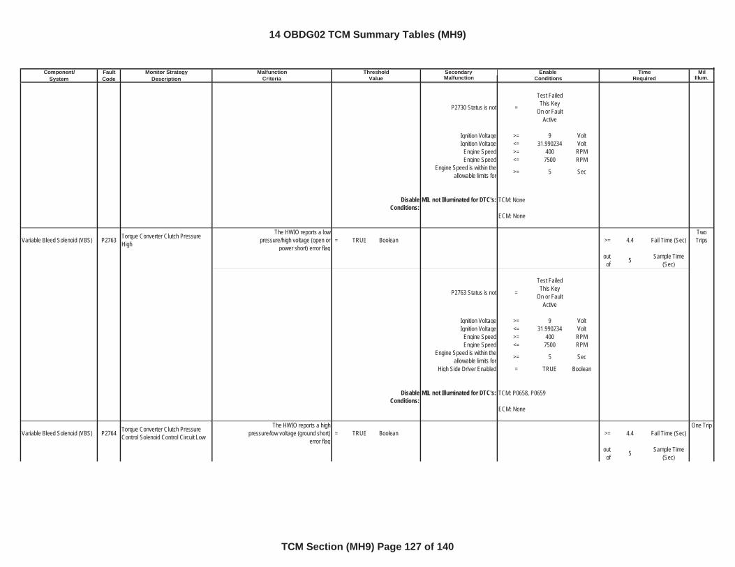
Component/ Fault Monitor Strategy Secondary MilSystem Code Description Malfunction Illum.
Malfunction Threshold Enable TimeCriteria Value Conditions Required
P2730 Status is not =
Test Failed This Key
On or Fault Active
Ignition Voltage >= 9 VoltIgnition Voltage <= 31.990234 Volt
Engine Speed >= 400 RPMEngine Speed <= 7500 RPM
Engine Speed is within the allowable limits for >= 5 Sec
DisableConditions:
MIL not Illuminated for DTC's:
Variable Bleed Solenoid (VBS) P2763 Torque Converter Clutch Pressure High
The HWIO reports a low pressure/high voltage (open or
power short) error flag= TRUE Boolean >= 4.4 Fail Time (Sec)
TwoTrips
outof 5 Sample Time
(Sec)
P2763 Status is not =
Test Failed This Key
On or Fault Active
Ignition Voltage >= 9 VoltIgnition Voltage <= 31.990234 Volt
Engine Speed >= 400 RPMEngine Speed <= 7500 RPM
Engine Speed is within the allowable limits for >= 5 Sec
High Side Driver Enabled = TRUE Boolean
DisableConditions:
MIL not Illuminated for DTC's:
Variable Bleed Solenoid (VBS) P2764 Torque Converter Clutch Pressure Control Solenoid Control Circuit Low
The HWIO reports a high pressure/low voltage (ground short)
error flag= TRUE Boolean >= 4.4 Fail Time (Sec)
One Trip
outof 5 Sample Time
(Sec)
TCM: P0658, P0659
ECM: None
TCM: None
ECM: None
14 OBDG02 TCM Summary Tables (MH9)
TCM Section (MH9) Page 127 of 140
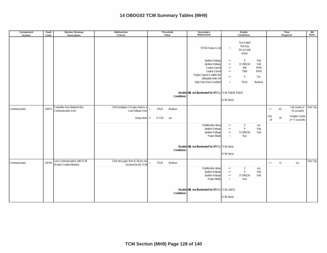
Component/ Fault Monitor Strategy Secondary MilSystem Code Description Malfunction Illum.
Malfunction Threshold Enable TimeCriteria Value Conditions Required
P2764 Status is not =
Test Failed This Key
On or Fault Active
Ignition Voltage >= 9 VoltIgnition Voltage <= 31.990234 Volt
Engine Speed >= 400 RPMEngine Speed <= 7500 RPM
Engine Speed is within the allowable limits for >= 5 Sec
High Side Driver Enabled = TRUE Boolean
DisableConditions:
MIL not Illuminated for DTC's:
Communication U0073 Controller Area Network Bus Communication Error
CAN Hardware Circuitry Detects a Low Voltage Error = TRUE Boolean >= 62 Fail counts (
10 seconds)One Trip
Delay timer >= 0.1125 sec Outof 70 Sample Counts
( 11 seconds)
Stabilization delay >= 3 secIgnition Voltage >= 9 VoltIgnition Voltage <= 31.990234 Volt
Power Mode = Run
DisableConditions:
MIL not Illuminated for DTC's:
Communication U0100 Lost Communications with ECM (Engine Control Module)
CAN messages from ECM are not received by the TCM = TRUE Boolean >= 12 sec One Trip
Stabilization delay >= 3 secIgnition Voltage >= 9 VoltIgnition Voltage <= 31.990234 Volt
Power Mode = Run
DisableConditions:
MIL not Illuminated for DTC's:
TCM: P0658, P0659
ECM: None
TCM: None
ECM: None
TCM: U0073
ECM: None
14 OBDG02 TCM Summary Tables (MH9)
TCM Section (MH9) Page 128 of 140
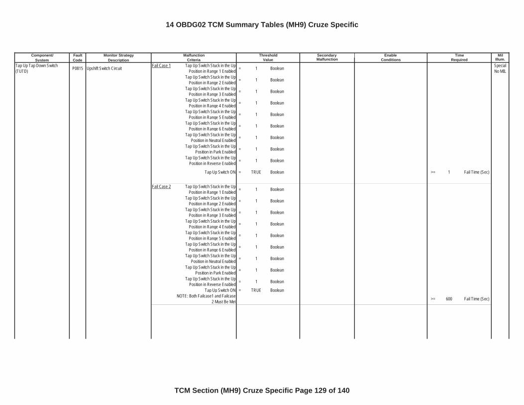
Component/ Fault Monitor Strategy Secondary MilSystem Code Description Malfunction Illum.
Tap Up Tap Down Switch (TUTD) P0815 Upshift Switch Circuit Fail Case 1 Tap Up Switch Stuck in the Up
Position in Range 1 Enabled = 1 Boolean Special No MIL
Tap Up Switch Stuck in the Up Position in Range 2 Enabled = 1 Boolean
Tap Up Switch Stuck in the Up Position in Range 3 Enabled = 1 Boolean
Tap Up Switch Stuck in the Up Position in Range 4 Enabled = 1 Boolean
Tap Up Switch Stuck in the Up Position in Range 5 Enabled = 1 Boolean
Tap Up Switch Stuck in the Up Position in Range 6 Enabled = 1 Boolean
Tap Up Switch Stuck in the Up Position in Neutral Enabled = 1 Boolean
Tap Up Switch Stuck in the Up Position in Park Enabled = 1 Boolean
Tap Up Switch Stuck in the Up Position in Reverse Enabled = 1 Boolean
Tap Up Switch ON = TRUE Boolean >= 1 Fail Time (Sec)
Fail Case 2 Tap Up Switch Stuck in the Up Position in Range 1 Enabled = 1 Boolean
Tap Up Switch Stuck in the Up Position in Range 2 Enabled = 1 Boolean
Tap Up Switch Stuck in the Up Position in Range 3 Enabled = 1 Boolean
Tap Up Switch Stuck in the Up Position in Range 4 Enabled = 1 Boolean
Tap Up Switch Stuck in the Up Position in Range 5 Enabled = 1 Boolean
Tap Up Switch Stuck in the Up Position in Range 6 Enabled = 1 Boolean
Tap Up Switch Stuck in the Up Position in Neutral Enabled = 1 Boolean
Tap Up Switch Stuck in the Up Position in Park Enabled = 1 Boolean
Tap Up Switch Stuck in the Up Position in Reverse Enabled = 1 Boolean
Tap Up Switch ON = TRUE BooleanNOTE: Both Failcase1 and Failcase
2 Must Be Met >= 600 Fail Time (Sec)
Malfunction Threshold Enable TimeCriteria Value Conditions Required
14 OBDG02 TCM Summary Tables (MH9) Cruze Specific
TCM Section (MH9) Cruze Specific Page 129 of 140
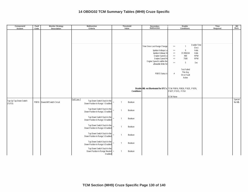
Component/ Fault Monitor Strategy Secondary MilSystem Code Description Malfunction Illum.
Malfunction Threshold Enable TimeCriteria Value Conditions Required
Time Since Last Range Change >= 1 Enable Time (Sec)
Ignition Voltage Lo >= 9 VoltsIgnition Voltage Hi <= 31.990234 VoltsEngine Speed Lo >= 400 RPMEngine Speed Hi <= 7500 RPM
Engine Speed is within the allowable limits for >= 5 Sec
P0815 Status is
Test Failed This Key
On or Fault Active
DisableConditions:
MIL not Illuminated for DTC's:
Tap Up Tap Down Switch (TUTD) P0816 Downshift Switch Circuit
Fail Case 1 Tap Down Switch Stuck in the Down Position in Range 1 Enabled = 1 Boolean
Special No MIL
Tap Down Switch Stuck in the Down Position in Range 2 Enabled = 1 Boolean
Tap Down Switch Stuck in the Down Position in Range 3 Enabled = 1 Boolean
Tap Down Switch Stuck in the Down Position in Range 4 Enabled = 1 Boolean
Tap Down Switch Stuck in the Down Position in Range 5 Enabled = 1 Boolean
Tap Down Switch Stuck in the Down Position in Range 6 Enabled = 1 Boolean
Tap Down Switch Stuck in the Down Position in Range Neutral
Enabled= 1 Boolean
TCM: P0816, P0826, P182E, P1876, P1877, P1915, P1761
ECM: None
14 OBDG02 TCM Summary Tables (MH9) Cruze Specific
TCM Section (MH9) Cruze Specific Page 130 of 140
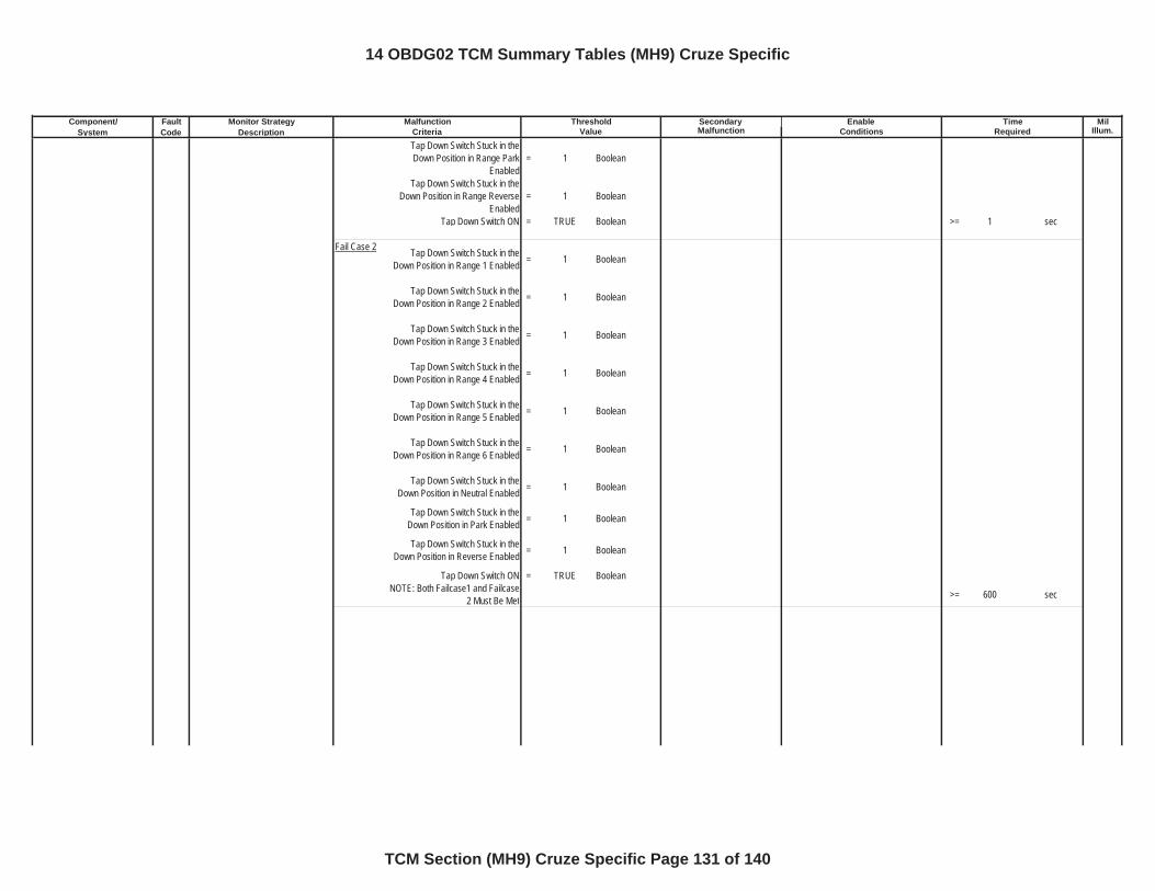
Component/ Fault Monitor Strategy Secondary MilSystem Code Description Malfunction Illum.
Malfunction Threshold Enable TimeCriteria Value Conditions RequiredTap Down Switch Stuck in the Down Position in Range Park
Enabled= 1 Boolean
Tap Down Switch Stuck in the Down Position in Range Reverse
Enabled= 1 Boolean
Tap Down Switch ON = TRUE Boolean >= 1 sec
Fail Case 2 Tap Down Switch Stuck in the Down Position in Range 1 Enabled = 1 Boolean
Tap Down Switch Stuck in the Down Position in Range 2 Enabled = 1 Boolean
Tap Down Switch Stuck in the Down Position in Range 3 Enabled = 1 Boolean
Tap Down Switch Stuck in the Down Position in Range 4 Enabled = 1 Boolean
Tap Down Switch Stuck in the Down Position in Range 5 Enabled = 1 Boolean
Tap Down Switch Stuck in the Down Position in Range 6 Enabled = 1 Boolean
Tap Down Switch Stuck in the Down Position in Neutral Enabled = 1 Boolean
Tap Down Switch Stuck in the Down Position in Park Enabled = 1 Boolean
Tap Down Switch Stuck in the Down Position in Reverse Enabled = 1 Boolean
Tap Down Switch ON = TRUE BooleanNOTE: Both Failcase1 and Failcase
2 Must Be Met >= 600 sec
14 OBDG02 TCM Summary Tables (MH9) Cruze Specific
TCM Section (MH9) Cruze Specific Page 131 of 140
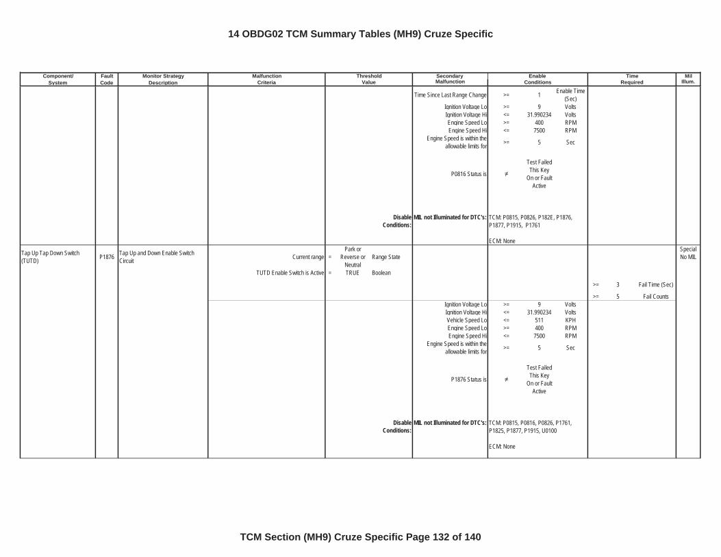
Component/ Fault Monitor Strategy Secondary MilSystem Code Description Malfunction Illum.
Malfunction Threshold Enable TimeCriteria Value Conditions Required
Time Since Last Range Change >= 1 Enable Time (Sec)
Ignition Voltage Lo >= 9 VoltsIgnition Voltage Hi <= 31.990234 VoltsEngine Speed Lo >= 400 RPMEngine Speed Hi <= 7500 RPM
Engine Speed is within the allowable limits for >= 5 Sec
P0816 Status is
Test Failed This Key
On or Fault Active
DisableConditions:
MIL not Illuminated for DTC's:
Tap Up Tap Down Switch (TUTD) P1876 Tap Up and Down Enable Switch
Circuit Current range =Park or
Reverse or Neutral
Range StateSpecial No MIL
TUTD Enable Switch is Active = TRUE Boolean
>= 3 Fail Time (Sec)
>= 5 Fail CountsIgnition Voltage Lo >= 9 VoltsIgnition Voltage Hi <= 31.990234 VoltsVehicle Speed Lo <= 511 KPHEngine Speed Lo >= 400 RPMEngine Speed Hi <= 7500 RPM
Engine Speed is within the allowable limits for >= 5 Sec
P1876 Status is
Test Failed This Key
On or Fault Active
DisableConditions:
MIL not Illuminated for DTC's: TCM: P0815, P0816, P0826, P1761, P1825, P1877, P1915, U0100
ECM: None
TCM: P0815, P0826, P182E, P1876, P1877, P1915, P1761
ECM: None
14 OBDG02 TCM Summary Tables (MH9) Cruze Specific
TCM Section (MH9) Cruze Specific Page 132 of 140
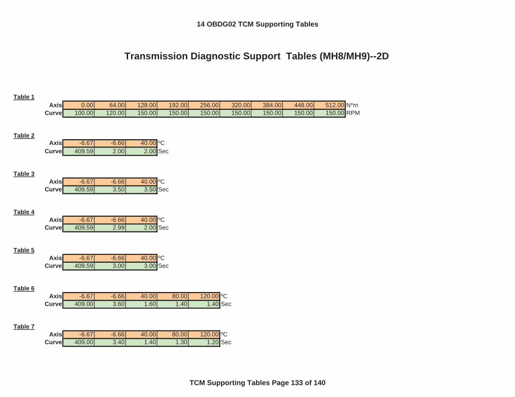
Table 1Axis 0.00 64.00 128.00 192.00 256.00 320.00 384.00 448.00 512.00 N*m
Curve 100.00 120.00 150.00 150.00 150.00 150.00 150.00 150.00 150.00 RPM
Table 2Axis -6.67 -6.66 40.00 ºC
Curve 409.59 2.00 2.00 Sec
Table 3Axis -6.67 -6.66 40.00 ºC
Curve 409.59 3.50 3.50 Sec
Table 4Axis -6.67 -6.66 40.00 ºC
Curve 409.59 2.99 2.00 Sec
Table 5Axis -6.67 -6.66 40.00 ºC
Curve 409.59 3.00 3.00 Sec
Table 6Axis -6.67 -6.66 40.00 80.00 120.00 ºC
Curve 409.00 3.60 1.60 1.40 1.40 Sec
Table 7Axis -6.67 -6.66 40.00 80.00 120.00 ºC
Curve 409.00 3.40 1.40 1.30 1.20 Sec
Transmission Diagnostic Support Tables (MH8/MH9)--2D
14 OBDG02 TCM Supporting Tables
TCM Supporting Tables Page 133 of 140

Transmission Diagnostic Support Tables (MH8/MH9)--2D
Table 8Axis -6.67 -6.66 40.00 80.00 120.00 ºC
Curve 409.00 3.60 1.60 1.50 1.40 Sec
Table 9Axis -6.67 -6.66 40.00 80.00 120.00 ºC
Curve 409.00 3.30 1.30 1.20 1.10 Sec
Table 10Axis -6.67 -6.66 40.00 80.00 120.00 ºC
Curve 8.85 3.75 1.31 0.28 0.28 Sec
Table 11Axis -6.67 -6.66 40.00 80.00 120.00 ºC
Curve 5.00 1.70 0.40 0.25 0.25 Sec
Table 12Axis -6.67 -6.66 40.00 80.00 120.00 ºC
Curve 8.00 2.20 0.70 0.25 0.25 Sec
Table 13Axis -6.67 -6.66 40.00 80.00 120.00 ºC
Curve 5.20 1.60 0.50 0.25 0.25 Sec
Table 14Axis -6.67 -6.66 40.00 80.00 120.00 ºC
Curve 5.00 1.50 0.70 0.25 0.25 Sec
Table 15
14 OBDG02 TCM Supporting Tables
TCM Supporting Tables Page 134 of 140
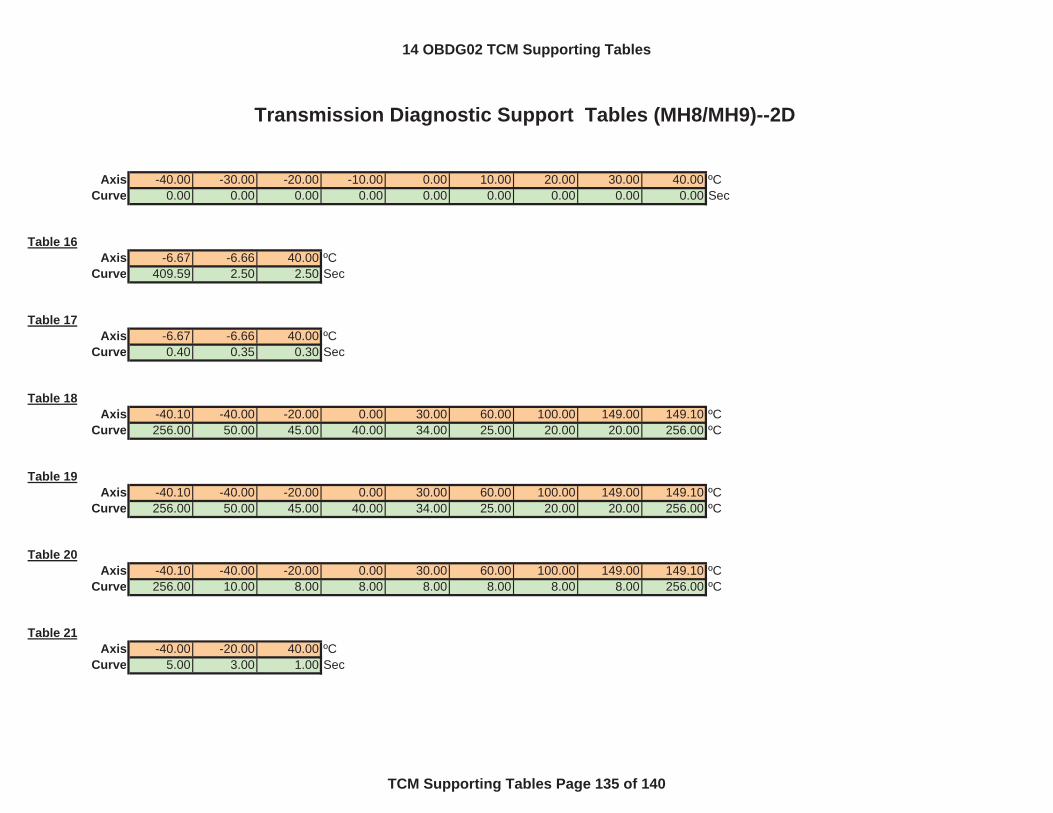
Transmission Diagnostic Support Tables (MH8/MH9)--2D
Axis -40.00 -30.00 -20.00 -10.00 0.00 10.00 20.00 30.00 40.00 ºCCurve 0.00 0.00 0.00 0.00 0.00 0.00 0.00 0.00 0.00 Sec
Table 16Axis -6.67 -6.66 40.00 ºC
Curve 409.59 2.50 2.50 Sec
Table 17Axis -6.67 -6.66 40.00 ºC
Curve 0.40 0.35 0.30 Sec
Table 18Axis -40.10 -40.00 -20.00 0.00 30.00 60.00 100.00 149.00 149.10 ºC
Curve 256.00 50.00 45.00 40.00 34.00 25.00 20.00 20.00 256.00 ºC
Table 19Axis -40.10 -40.00 -20.00 0.00 30.00 60.00 100.00 149.00 149.10 ºC
Curve 256.00 50.00 45.00 40.00 34.00 25.00 20.00 20.00 256.00 ºC
Table 20Axis -40.10 -40.00 -20.00 0.00 30.00 60.00 100.00 149.00 149.10 ºC
Curve 256.00 10.00 8.00 8.00 8.00 8.00 8.00 8.00 256.00 ºC
Table 21Axis -40.00 -20.00 40.00 ºC
Curve 5.00 3.00 1.00 Sec
14 OBDG02 TCM Supporting Tables
TCM Supporting Tables Page 135 of 140
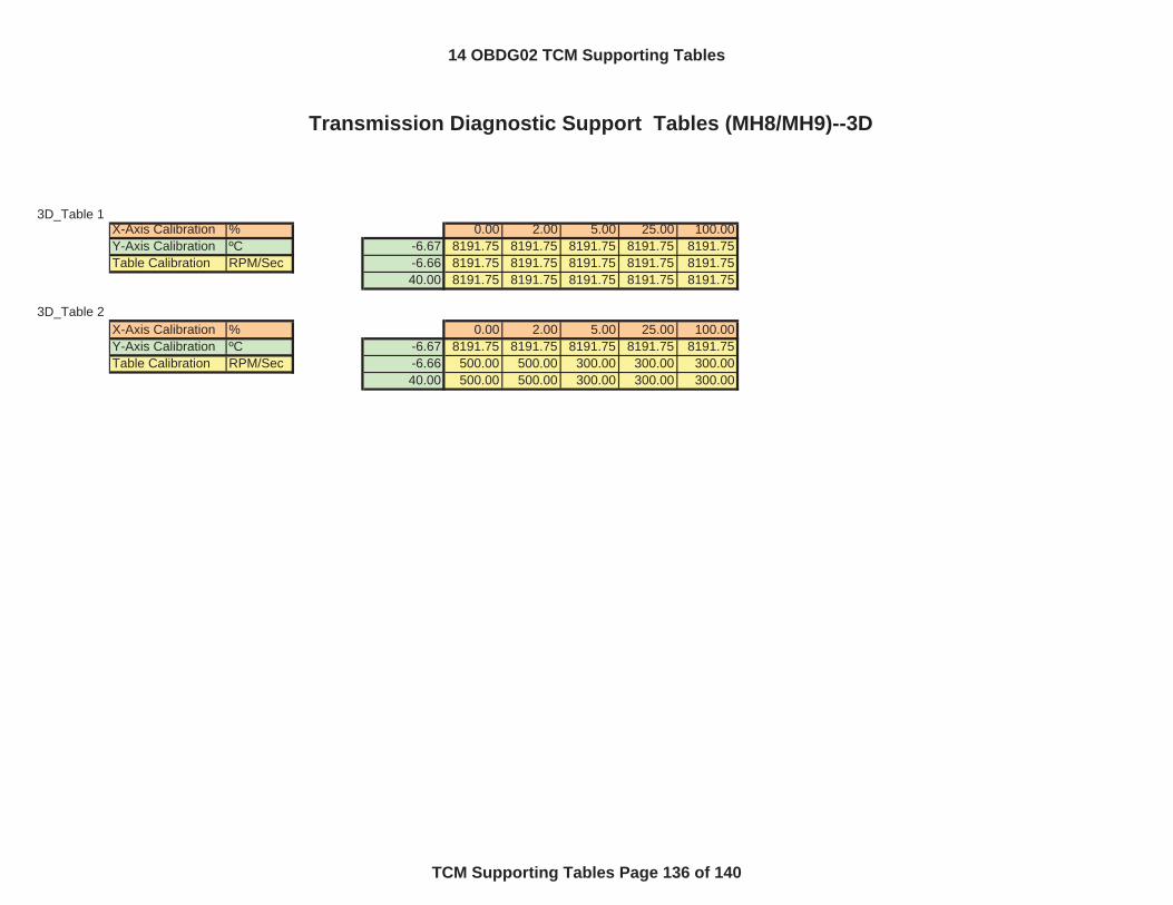
3D_Table 1X-Axis Calibration % 0.00 2.00 5.00 25.00 100.00Y-Axis Calibration ºC -6.67 8191.75 8191.75 8191.75 8191.75 8191.75Table Calibration RPM/Sec -6.66 8191.75 8191.75 8191.75 8191.75 8191.75
40.00 8191.75 8191.75 8191.75 8191.75 8191.75
3D_Table 2X-Axis Calibration % 0.00 2.00 5.00 25.00 100.00Y-Axis Calibration ºC -6.67 8191.75 8191.75 8191.75 8191.75 8191.75Table Calibration RPM/Sec -6.66 500.00 500.00 300.00 300.00 300.00
40.00 500.00 500.00 300.00 300.00 300.00
Transmission Diagnostic Support Tables (MH8/MH9)--3D
14 OBDG02 TCM Supporting Tables
TCM Supporting Tables Page 136 of 140
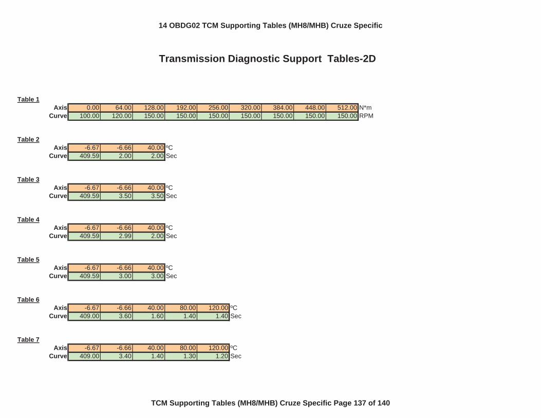
Table 1Axis 0.00 64.00 128.00 192.00 256.00 320.00 384.00 448.00 512.00 N*m
Curve 100.00 120.00 150.00 150.00 150.00 150.00 150.00 150.00 150.00 RPM
Table 2Axis -6.67 -6.66 40.00 ºC
Curve 409.59 2.00 2.00 Sec
Table 3Axis -6.67 -6.66 40.00 ºC
Curve 409.59 3.50 3.50 Sec
Table 4Axis -6.67 -6.66 40.00 ºC
Curve 409.59 2.99 2.00 Sec
Table 5Axis -6.67 -6.66 40.00 ºC
Curve 409.59 3.00 3.00 Sec
Table 6Axis -6.67 -6.66 40.00 80.00 120.00 ºC
Curve 409.00 3.60 1.60 1.40 1.40 Sec
Table 7Axis -6.67 -6.66 40.00 80.00 120.00 ºC
Curve 409.00 3.40 1.40 1.30 1.20 Sec
Transmission Diagnostic Support Tables-2D
14 OBDG02 TCM Supporting Tables (MH8/MHB) Cruze Specific
TCM Supporting Tables (MH8/MHB) Cruze Specific Page 137 of 140
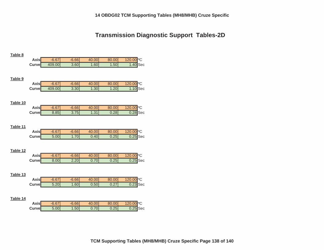
Transmission Diagnostic Support Tables-2D
Table 8Axis -6.67 -6.66 40.00 80.00 120.00 ºC
Curve 409.00 3.60 1.60 1.50 1.40 Sec
Table 9Axis -6.67 -6.66 40.00 80.00 120.00 ºC
Curve 409.00 3.30 1.30 1.20 1.10 Sec
Table 10Axis -6.67 -6.66 40.00 80.00 120.00 ºC
Curve 8.85 3.75 1.31 0.28 0.28 Sec
Table 11Axis -6.67 -6.66 40.00 80.00 120.00 ºC
Curve 5.00 1.70 0.40 0.25 0.25 Sec
Table 12Axis -6.67 -6.66 40.00 80.00 120.00 ºC
Curve 8.00 2.20 0.70 0.25 0.25 Sec
Table 13Axis -6.67 -6.66 40.00 80.00 120.00 ºC
Curve 5.20 1.60 0.50 0.27 0.23 Sec
Table 14Axis -6.67 -6.66 40.00 80.00 120.00 ºC
Curve 5.00 1.50 0.70 0.25 0.25 Sec
14 OBDG02 TCM Supporting Tables (MH8/MHB) Cruze Specific
TCM Supporting Tables (MH8/MHB) Cruze Specific Page 138 of 140
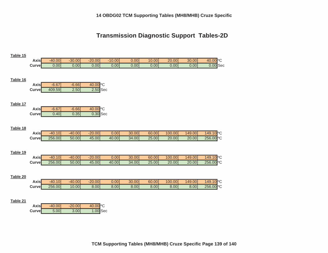
Transmission Diagnostic Support Tables-2D
Table 15Axis -40.00 -30.00 -20.00 -10.00 0.00 10.00 20.00 30.00 40.00 ºC
Curve 0.00 0.00 0.00 0.00 0.00 0.00 0.00 0.00 0.00 Sec
Table 16Axis -6.67 -6.66 40.00 ºC
Curve 409.59 2.50 2.50 Sec
Table 17Axis -6.67 -6.66 40.00 ºC
Curve 0.40 0.35 0.30 Sec
Table 18Axis -40.10 -40.00 -20.00 0.00 30.00 60.00 100.00 149.00 149.10 ºC
Curve 256.00 50.00 45.00 40.00 34.00 25.00 20.00 20.00 256.00 ºC
Table 19Axis -40.10 -40.00 -20.00 0.00 30.00 60.00 100.00 149.00 149.10 ºC
Curve 256.00 50.00 45.00 40.00 34.00 25.00 20.00 20.00 256.00 ºC
Table 20Axis -40.10 -40.00 -20.00 0.00 30.00 60.00 100.00 149.00 149.10 ºC
Curve 256.00 10.00 8.00 8.00 8.00 8.00 8.00 8.00 256.00 ºC
Table 21Axis -40.00 -20.00 40.00 ºC
Curve 5.00 3.00 1.00 Sec
14 OBDG02 TCM Supporting Tables (MH8/MHB) Cruze Specific
TCM Supporting Tables (MH8/MHB) Cruze Specific Page 139 of 140
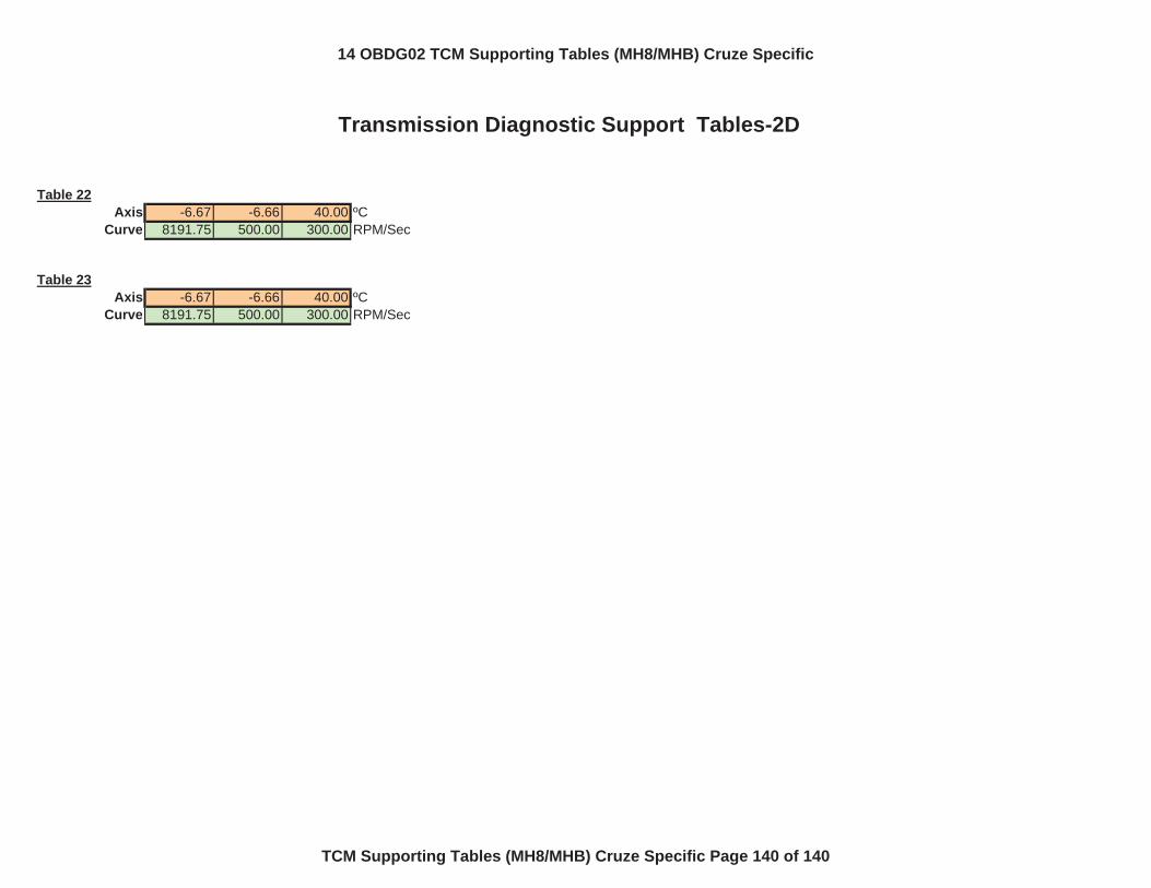
Transmission Diagnostic Support Tables-2D
Table 22Axis -6.67 -6.66 40.00 ºC
Curve 8191.75 500.00 300.00 RPM/Sec
Table 23Axis -6.67 -6.66 40.00 ºC
Curve 8191.75 500.00 300.00 RPM/Sec
14 OBDG02 TCM Supporting Tables (MH8/MHB) Cruze Specific
TCM Supporting Tables (MH8/MHB) Cruze Specific Page 140 of 140