Embed Size (px)
Citation preview

/ Discussions
of the
13th International Workshop
Water Waves and Jaoatipg Bodies
>e^>
29 March - 1 April 1998
Alphcn aan den Rijn, The Netherlands
Kflitor: A.J. Hermans

REPORT DOCUMENTATION PAGE OMB No. 0704-0188
^nThdM» o) «term«. Sxl omiwm «0»*» *» bad«. Mm» « inv «Mr «wet of *• O-a» ot nlotm««i ncUvg w>n I« rrtucfig tt» tu««i I. VMrioton Hudguan« Snat Di.n««t I» bttanta Opnum «id lUpora. 121SJ^tanon DM Htfwy. Guiu 1204. Mngton. VA 22202-4301 md to ft. Off» ot MiracmM and MM. Parwmrk teductm Ptojtct (0704-018BI, WMiington. DC 20503.
1. AGENCY USE ONLY (Lam blank) 2. REPORT DATE
May 1998
3. REPORT TYPE AMD DATES COVERED
Final 29 March -1 April 1998 4. TITLE AND SUBTITLE
Discussions of the 13th International Workshop on Water Waves and Floating Bodies
6. AUTHOR(S)
A.J. Hermans
7. PERFORMING ORGANIZATION NAME(S) AND ADDRESSES)
A. J. Hermans Department of Applied Mathematics Delft University of Technology PO Box 5031 2600 fiA Delft The Netherlands 9. SPONSORING/MONITORING AGENCY NAME(S) AND ADDRESSES)
Technical Director Office of Naval Research International Field Office PSC 802 Box 39 FPO AE 09499-0700
5. FUNDING NUMBERS
N00014-98-1-1021
8. PERFORMING ORGANIZATION REPORT NUMBER
10.SPQNS0RINGJM0NIT0RING AGENCY REPORT NUMBER
II.SUPPLEMENTARY NOTES
12a. DISTRIBUTION AVAILABILITY STATEMENT
Approved for public release, distribution is unlimited 12b. DISTRIBUTION CODE
13. ABSTRACT (Maximum 200 words)
The Thirteenth International Workshop on Water Waves and Floating Bodies was organized by the Department of Applied Mathematics (ITS), in cooperation with the Department of Marine Technology (DEP) of the Delft University of Technology and held in Alphen aan den Rijn from 29 March till 1 April, 1998. This particular location was chosen to obtain an optimal interaction between the participants, both sociably and scientifically.
A total of 46 papers was presented, these presentations were selected on the basis of extended abstracts. The selection has been carried out by a committee consisting of the host together with his two predecessors, Dr. Volker Bertram of the University of Hamburg and Prof. Bernard Molin of the Ecole Superiure d'Ingenieurs de Marseille.
The 79 participants comprises the authors (also of rejected abstracts), session chairmen and representatives of sponsoring
organisations.
14. SUBJECT TERMS
Key Words: Green function, waves and current, free-surface, Rankine method, oscillatory bodies, wave decay, hydroelastic deflection, ship motion, gravity wave systems, wave pattern
analysis 17. SECURITY CLASSIFICATION
OF REPORT 18. SECURITY CLASSIFICATION
OF THIS PAGE
19. SECURITY CLASSIFICATION OF ABSTRACT
IS. NUMBER OF PAGES
16. PRICE CODE
20. LIM""
Stand Prater« DMO»'
I tr

Discussions
of the
13th International Workshop
on
Water Waves and Floating Bodies
29 March - 1 April 1998
Alphen aan den Rijn, The Netherlands
Edited by A.J. Hermans
Department of Applied Mathematics Delft University of Technology
UJSPECnSDl
*-*4

ISBN 90-407-1720-6 /CIP
Copyright © 1998 by A.J. Hermans
All rights reserved. No part of the material protected by this copyright notice may be reproduced or utilized in any form or by any means, electronic or mechanical, including photocopying, recording or by any information storage and retrieval system, without permission from the publisher.
Printed in the Netherlands

The Workshop is sponsored by
M TU Delft Delft University ol Technology
Avt fseas Enginaering bv
Delft University of Technology
Allseas Engineering
EEESa Maritime Research Institute Netherlands
blueuuoter engineering b.v. Bluewater Engineering
5fFsfHDRESYSTEMS
I JGUSTO ENGINEERING
EJ MARINE
CONTRACTORS
Single Buoy Moorings Inc.
IHC Gusto Engineering B.V.
Heerema Offshore Construction Group b.v.
s ü.M. Burgerscentrum Onderzoekschool voor Stromingsleer
Ministerie van Verkeer en Waterstaat/ Directoraat-Generaal Goederenvervoer
Office of Naval Research Europe
This work relates to Department of the Navy Grant N00014-98-1-1021 issued by the Office of Naval Research European Office. The United States has a royalty-free license throughout the world in all copyrightable material contained herein.
PREFACE
The Thirteenth International Workshop on Water Waves and Floating Bodies was ongan- ized by the Department of Applied Mathematics (ITS), in cooperation with the Depart- ment of Marine Technology (DEP) of the Delft University of Technology and held in Alphen aan den Rijn from 29 March till 1 April, 1998. This particular location was chosen to obtain an optimal interaction between the participants, both sociably and scientifically.
A total of 46 papers was presented. These presentations were selected on the basis of extended abstracts. The selection has been carried out by a committee consisting of the host together with his two predecessors, Dr. Volker Bertram of the University of Hamburg and Prof. Bernard Molin of the Ecole Superieure d'Ingenieurs de Marseille.
The 79 participants comprises the authors (also of rejected abstracts), session chairmen and representatives of sponsoring organisations.
We thank the sponsors for their generous financial support. We could keep the cost at a reasonable level and solve the budgetary problems for many of the participants. Thanks to Prof. Jo Pinkster who contacted most of the sponsors.
Judith Ormskerk took care of the production of the proceedings and its supplement and not to forget the final arrangements for the workshop in the birdpark Avifauna. Due to her contribution we could have a successful meeting.
Each participant has obtained the proceedings, with the extended abstracts, a few weeks in advance. This is one of the traditions of these workshops and as a result the discus- sions have been of high scientific level. This second part (supplement) of the proceedings reports of these discussions. Also the abstract of the presentation of S.J. Cox and M.J. Cooker, the program and the list of participants are included.
Just before the meeting we lost a dear friend and colleague. Ralph Kleinman died on February 23, 1998. In the past he contributed to some of the workshops and intended to participate this one, as well. Kleinman is known for his work on integral equations and op- timization techniques applied to problems in scattering and wave propagation. Although his major field of interest was acoustic and electromagnetic scattering he contributed to water waves, as well. He was convinced that his approach concerning shape optimization in acoustic scattering could lead to interesting results in ship hydrodynamics. Together with his colleagues at the Universities of Delaware and Tel Aviv, Kleinman has prepared a presentation on this topic. The abstract of his intended presentation is in the proceedings. Unfortunately the presentation could not take place. It is up to the scientific community to pursue his line of research.
Aad J. Hermans Delft, May 1998

II
CONTENTS
Harry B. Bingham, Computing the Green function for linear wave-body interaction
Discusser(s): X.-B. Chen 1
Bjarne Büchmann, Pierre Ferrant and Jesper Skourup, Runup on a body in waves and current. Fully non-linear and finite order calculations
Discusser(s): M.W. Dingemans 2-3 R.C.T. Rainey 4 H.C. Raven 6
Tim H.J. Bunnik and Aad J. Hermans, Stability analysis for the 3D unsteady
free-surface condition with raised panels Discusser(s): M.W. Dingemans 7
J. Grue 8
M. Kashiwagi 9 Y. Kim 10 W.W. Schultz 11
Xiao-Bo Chen and Francis Noblesse, Super Green functions for generic
dispersive waves Discusser(s): H. Iwashita 12
Alain H. Clement, Computation of impulse response function using differential
properties of the time-domain Green function Discusser(s): X.-B. Chen 14
Simon J. Cox and Mark J. Cooker, The effect of wave impact on a body in the
breaker zone Abstract I5
Discusser(s): A.A. Korobkin 19 P.A. Tyvand 20
Heike Cramer, Volker Bertram and Gerhart Thiart, A fully 3-d Rankine method for ship seakeeping
Discusser(s): R.F. Beck 21 P.A. Tyvand 20
Donald Danmeier, Multiple-body simulations using a higher-order panel code Discusser(s): H.J. Prins 22
Odd M. Faltinsen and Rong Zhao, Water entry of a wedge into a channel Discusser(s): A.A. Korobkin 23
J.N. Newman 24 J. Pinkster 25
Ill
Emmanuel Fontaine and M.P. Tulin, On the generation of wave free oscillatory bodies and of trapped modes
Discusser(s): Q.W. Ma 26 M. Mclver 27 J.N. Newman 28 F. Ursell 30
Erratum 31
Stephan T. Grilli and Zhimin Hu, Modeling of instabilities of oil containment systems by a vortex sheet method
Discusser(s): E. Palm 32 W.W. Schultz 33
Hidetsugu Iwashita, Influence of the steady flow in seakeeping of a blunt ship through the free-surface condition
Discusser(s): X.-B. Chen 34 R.C.T. Rainey 35 K. Takagi 36
Hiroshi Kagemoto, Wave decay characteristics along a long array of cylindrical legs
Discusser(s): D. Evans 37 M. Mclver 38 J.N. Newman 39
Seppo Kalske, Unsteady bow wave field and added resistance of skips in short waves
Discusser(s): A.A. Korobkin 40 K. Takagi 41
Masashi Kashiwagi, A new direct method for calculating hydroelastic deflection of a very large floating structure in waves
Discusser(s): R. Eatock Taylor 42 S. Zhang 43
Yonghwan Kim and P.D. Sclavounos, A finite-depth unified theory of ship motion Discusser(s): J.A.P. Aranha 44
J. Grue 45 M. Kashiwagi 49 B. Molin 50
M. Landrini, O. Oshri, T. Waseda and M.P. Tulin, Long time evolution of gravity wave systems
Discusser(s): M.W. Dingemans 51 S. Grilli 52 R.C.T. Rainey 53 W.W. Schultz 54
IV .
C. Levi, S. Welch, E. Fontaine and M.P. Tulin, Experiments on the ringing response of an elastic cylinder in breaking wave groups
Discusser(s): R.C.T. Rainey 55
CM. Linton, Rapidly convergent representations for free-surface Green's functions Discusser(s): A.H. Clement 58
N. Kuznetsov 59 W.W. Schultz 60
Q.W. Ma, G.X. Wu and R. Eatock Taylor, Numerical simulation of sloshing
waves in a 3D tank Discusser(s): V. Bertram 61
W.W. Schultz 62
Maureen Mclver, Uniqueness, trapped modes and the cut-off frequency Discusser(s): N. Kuznetsov 63
CM. Linton 64
P. Mclver, On the completeness of eigenfunction expansions in water-wave problems Discusser(s): A.H. Clement 65
D. Evans 66
Bernard Molin and Y. Stassen, A procedure to remove secularity in third-order
numerical wave tanks Discusser(s): B. Büchmann 67
M.W. Dingemans 68
O. Motygin and N. Kuznetsov, Non-uniqueness in the water-wave problem: an
example violating the inside John condition Discusser(s): M. Mclver 69
D. Evans 70
J.N. Newman, Hydrodynamic analysis of the Mclver toroid Discusser(s): X.-B. Chen '. 71
D. Evans 72 N. Kuznetsov 73 CM. Linton 74 R.C.T. Rainey 75 S. Zhang 78
Hoyte C. Raven and Henk J. Prins, Wave pattern analysis applied to nonlinear ship wave calculations
Discusser(s): R.F. Beck 79 S.D. Sharma 80
Erratum 81

V
Anil K. Subramani, Robert F. Beck and William W. Schultz, Suppression of wave-breaking in nonlinear water wave computations
Discusser(s): E. van Daalen 82 M.W. Dingemans 83 H.C. Raven 84 S.D. Sharma 85
Peder A. Tyvand, Free-surface evolution at the edge of an impulsively upwelling fluid layer
Discusser(s): E. van Daalen 86 W.W. Schultz 88
T. Utsunomiya and R. Eatock Taylor, Analogies for resonances in wave diffraction problems
Discusser(s): CM. Linton 90 Erratum 91
Riaan van 't Veer, Experimental validation of a Rankine panel method Discusser(s): X.-B. Chen 92
H.C. Raven 93
William C. Webster and Xinyu Zhang, A waterfall springing from unsteady flow over an uneven bottom
Discusser(s): S. Grilli 94 J. Grue 95 W.W. Schultz 96
Jaap-Harm Westhuis and Andonowati, Applying the finite element method in numerically solving the two dimensional free-surface water wave equations
Discusser(s): S. Grilli 97 Q.W. Ma 99
D.J. Wood and D.H. Peregrine, Pressure-impulse theory for water wave impact on a structure with trapped air
Discusser(s): A.A. Korobkin 101
Sheguang Zhang, Woei-Min Lin, Kenneth Weems and Dick K.P. Yue, A hybrid boundary-element method for non-wall-sided bodies with or without forward speed
Discusser(s): X.-B. Chen 102 H. Kagemoto 103 M. Kashiwagi 104
Programme A-E
List of Participants a-h

13th International Workshop on Water Waves and Floating Bodies
Title of Abstract : Computing the Green function for linear wave-body interaction
Author(s) : H.B. Bingham
Discusser : X.-B. Chen
Questions/comments:
You define the Green function which satisfies a "Dirac" condition involving the normal derivative at a point on the body surface. What happens for double derivatives at/near this point? In other words is the Laplace equation still satisfied at this point?
Author's reply:
The Green function actually satifies a Poisson equation, so now it does not satisfy the Laplace equation at one point on the body. Physically meaningful quantities are always obtained by integrating the Green function over the body however, and therefore will satisfy the Laplace equation everywhere.

13th International Workshop on Water Waves and Floating Bodies
Title of Abstract : Runup on a body in waves and current. Fully non-linear and finite order calculations
Author(s) : B. Büchmann, P. Ferrant and J. Skourup
Discusser : M.W. Dingemans
Questions/comments:
I do not understand the post-processing in which wave steepness may be chosen. For a second-order model wave steepness is part of the model and resulting wave forces are nonlinearly connected to the quantities. Or do you in fact do a linear computation and call it a second-order method?
Author's reply: (B. Büchmann)
It is a standard procedure to adapt a perturbation procedure to account for (weak) non- linearity. As noted in your book (Dingemans, 1997, section 2.8) "for the extension [from linear] to non-linear wave motion it is necessary to invoke some perturbation method". Choosing a Stokes expansion the problem is solved at first and second order at each time step. It is possible to non-dimensionalize both the first and the second order equations such that the dimensions of the wave height, H, can be chosen after the problem is solved. All first order quantities are then scaled by H, while the second order quantities are scaled by e.g. H2/h, where h is the water depth. There is nothing mysterious about this pro- cedure; it corresponds exactly to solving the progressive wave problem to second order for an unknown wave amplitude, a, thus finding a first order solution proportional to a, and a second order solution proportional to k * a2 (a can then be chosen after the general solution is found - thus " in a post-processing procedure").
Reference: Dingemans, M.W., (1997), "Water Wave Propagation over Unveven Bottoms", World Scientific Publishing, Singapore.
13th International Workshop on Water Waves and Floating Bodies
Title of Abstract
Author(s)
Discusser
Runup on a body in waves and current. Fully non-linear and finite order calculations
B. Büchmann, P. Ferrant and J. Skourup
M.W. Dingemans
Questions/comments:
In the abstract you note that spatial non-convergence is occurring. Can you expand on that?
Author's reply: (B. Büchmann)
We do not note spatial divergence. What we do note is that for some parameters (esp. when the Froude number increases) we cannot with the given (limited) computer resources obtain results that are fully converged in space. This is due to the fact that we have an upper bound on the number of panel that we can use. Increasing the density of the panels close to the cylinder will force us to either make the discretization to coarse in other areas, or move the truncation boundaries too close to the body. In both cases this will distort the solution also close to the body.

13th International Workshop on Water Waves and Floating Bodies
Title of Abstract : Runup on a body in waves and current. Fully non-linear and finite order calculations
Author(s) : B. Büchmann, P. Ferrant and J. Skourup
Discusser : R.C.T. Rainey
Questions/comments:
This is of course a most impressive piece of work. I am interested in the authors' remark at the end of their Introduction, that they have a "method for defining the domain of validity of finite order model(s)" i.e. models based on a "perturbation procedure about the still water level". This is because I have in [1] an argument that this perturbation procedure (which I refer to in [1] and [2] as "Stokes' expansion", incidentally) will diverge once the wave height reaches the cylinder diameter. And I would like to know if my argument, which is really a conjecture, is correct.
In particular, I am interested in the fully non-linear results from ANSWAVE given during the presentation by Huseby and Grue. These only covered wave heights below the cylinder diameter, which I understood to be because higher waves were too steep for ANSWAVE. But how about longer wavelengths, in deep water - would ANSWAVE then run for wave heights greater than the cylinder diameter?
I appreciate that the Keulegan-Carpenter number at the water surface (KC(S)) is then greater than pi, so that flow separation may perhaps begin. However, we did not see any significant separation in our "ringing" experiments [2] until KC(S) was at least double that, so that ANSWAVE results in this regime cannot be dismissed for this reason. (If anything, I would have thought that flow separation was much more of an issue in the cases you have run with steady current, in Figure 1 and 2).
[1 ] Rainey, R.C.T. 1995 "Slender-body expressions for the wave load on offshore struc- tures" Proc. R. Soc. Lond. Vol. A450, pp. 391-416.
[2 ] Chaplin, J.R., Rainey, R.C.T. & Yemm, R.W. 1997 "Ringing of a vertical cylinder in waves" J. Fluid Mech. Vol. 350, pp. 119-147.

13th International Workshop on Water Waves and Floating Bodies 5
Author's reply: (P. Ferrant)
Thanks for your kind comment.
Motivated by your question, we run new simulations using ANSWAVE with the same wavelength as in Huseby k Grue's paper, i.e. X/h = 1.2823 (h water depth), but with a cylinder radius reduced to R/h = 0.015, leading to kR = 0.0735. We have been able to run stable simulations in this configuration up to A/R about 1.4, which is well above the upper limit of convergence of Stokes expansion conjectured in [1]. But obviously this is not a proof that your conjecture is false, since ANSWAVE is NOT based on a Stokes expansion procedure. Then an interesting question is what would be the manifestation of the conjectured divergence in a fully non-linear simulation (or in experiments). In order to find some elements of answer, we plan to investigate the behaviour of ANSWAVE around A/R — 1.0, to see whether or not any change of regime occurs in this region.

13th International Workshop on Water Waves and Floating Bodies
Title of Abstract : Runup on a body in waves and current. Fully non-linear and finite order calculations
Author(s) : B. Büchmann, P. Ferrant and J. Skourup
Discusser : H.C. Raven
Questions/comments:
It is not quite clear to me why you say that the second order model poses higher resolution requirements than the non-linear model.
1. Are not the same short scattered waves inherent in the non-linear model?
2. Are they then damped, distorted or aliased in that model as well, for insufficient panel density?
Author's reply: (P. Ferrant)
The statement that the second order model requires finer meshes for convergence may seem surprising, but is based on the observation of the behavior of both numerical models. For some of the cases for which spatial convergence of second order quantities was difficult to obtain, fully non-linear simulations were repeated with finer meshes. No sensible differences with earlier results were observed, indicating that fully non-linear simulation results were reasonably converged.
1. It might well happen that some of the separate problems in the Stokes expansion series representation of the problem lead to stiffer solutions than the global fully non-linear solution. Both models presented in this paper are based on different approximations of the physical problem and, to the authors' knowledge, unique. The extremely good agreement of both models in the low Froude-low steepness regime is an indication that both theories are sound and have been correctly implemented.
2. Regarding the still unexplained difference of convergence behavior of both models in some particular combinations of parameters, other implementations of both the second order and fully non-linear theories of 3D wave-body-current interactions would be welcome for further validation.

13th International Workshop on Water Waves and Floating Bodies
Title of Abstract
Author(s)
Discusser
Stability analysis for solving the 3D unsteady free-surface condition with raised panels
T.H.J. Bunnik and A.J. Hermans
M.W. Dingemans
Questions/comments:
1. Do you have any idea why central-difference method becomes unstable?
2. Can it be chaotic behaviour, because central difference schemes are known to exhibit chaotic behaviour.
Author's reply:
1. Central differences become unstable if the speed of the stream is large. In that case, when a wave propagates in the same direction as the stream, we may only include points in the difference scheme which contain information about what the wave will be like in the future, so these points must lie upstream, opposite to the direction of propagation.
2. I do not think so, the numerical scheme also becomes unstable if we use "downwind" differences instead of central differences.
13th International Workshop on Water Waves and Floating Bodies
Title of Abstract
Author(s)
Discusser
Stability analysis for solving the 3D unsteady free-surface condition with raised panels
T.H.J. Bunnik and A.J. Hermans
J. Grue
Questions/comments:
By assuming that r > 1/4 some analytical problems are perhaps avoided. It would be interesting to see a similar stability analysis for r < 1/4, and for r —t 1/4. In the continnous case the Green function has singularity at r = 1/4, since two wavenum- bers merge there. The singularity disappears, however, if the wavenumbers are made slightly different, which may be the case in the discrete case.
Author's reply:
It is very easy to apply our stability analysis also for r < 1/4 and r —»■ 1/4. If r = 1/4 and we let the gridsize approach zero, we will find two identical wavenumbers like in the continuous case. The numerical scheme is according to our standards however still stable in this case, because in our analysis we do not look at the singular behaviour of the Green function. It is true of course, that because the wavenumbers differ at r = 1/4 for nonzero gridsize, this explains why Rankine panel methods have less problems with the singularity at T = 1/4 then panel methods using the Green function satisfying the Kelvin condition.

13th International Workshop on Water Waves and Floating Bodies
Title of Abstract
Author(s)
Discusser
Stability analysis for solving the 3D unsteady free-surface condition with raised panels
T.H.J. Bunnik and A.J. Hermans
M. Kashiwagi
Questions/comments:
In the discussion on the numerical damping, you emphasized that the 2nd order difference scheme is effective. I want to know the result when applying a higher order, say 3rd order scheme. If the singularity strength is represented by a non-constant function, say the /?-spline function, how will the results look like?
Author's reply:
A third order scheme reduces dispersion drastically, but the damping becomes slightly positive (amplification). If the singularity strength is a /8-spline, then we can calculate the derivatives in the free surface condition analytically with high precision. This will probably reduce the damping very much.

10 13th International Workshop on Water Waves and Floating Bodies
Title of Abstract
Author(s)
Discusser
Stability analysis for solving the 3D unsteady free-surface condition with raised panels
T.H.J. Bunnik and A.J. Hermans
Y.Kim
Questions/comments:
Your result seems very interesting. The result may provide the stability condition for various schemes. You showed some cases for numerical differentiation, but, if we can apply this method to higher order panels, we can forget the numerical differential for space. Do you have any experience or idea if the panel has a higher-order basis function?
Author's reply:
Using analytical derivatives from higher order basis functions will probably reduce damp- ing and dispersion. Some trick however has to be found to satisfy the radiation condition (for r > 1/4 waves propagate downstream), this can probably be done by shifting the collocation points upstream.

13th International Workshop on Water Waves and Floating Bodies 11
Title of Abstract
Author(s)
Discusser
Stability analysis for solving the 3D unsteady free-surface condition with raised panels
T.H.J. Bunnik and A.J. Hermans
W. Schultz
Questions/comments:
1. Is a = 1 for figure 1(b) and all later figures in your presentation?
2. How do you relate the k where the central difference scheme becomes unstable on your last figure of your presentation to the meshsize?
Author's reply:
1. Yes.
2. The meshsize was related to the length of the steady wave by Fn&x = 0.05, which means we have 20 panels per steady wavelength. We now send over this grid an unsteady wave at a range of wavenumbers. So for the point where the difference scheme becomes unstable in case of head waves, which happens k as 23, we have about 5| panels per wavelength.

12 13th International Workshop on Water Waves and Floating Bodies
Title of Abstract : Super green functions for generic dispersive waves
Author(s) : X.-B. Chen and F. Noblesse
Discusser : H. Iwashita
Questions/comments:
I think it is doubtful to conclude that your method is the "only" method for solving this kind of problem. We also applied the panel Green function (obtained by integrating the monopole source over the panel) to the practical boundary value problem and compared results with corresponding results by the ordinal monopole Green function method, in- creasing the number of panels on the ship surface up to 1000 or so. Then we could not see a remarkable difference. So we cannot say that the integration of the Green function over the panel promotes the cancelation of its singularity near the free surface provided the practical number of elements are used in the calculation. Ordinal monopole Green function method can be a practical method, too.
Author's reply:
It is well known that, in the limit of both source and field points being at the free surface, the Green function of wave diffraction-radiation with forward speed is extremely singular and highly oscillatory so that its integration in the usual approach (in which the Green function and its gradient are evaluated and subsequently integrated over a panel or a segment) is difficult and may not be robust, if not impossible, to get accurate precision for field points near a waterline-segment or a hull-panel at the free surface. Differently here, we consider directly free-surface potential flows (super Green functions) generated by an arbitrary distribution of singularities and summarize in our paper new mathem- atical representations of near-field and far-field waves of free-surface effects in a generic dispersive medium. We can show mathematically that the super Green function is not singular as far as a non-singular distribution of singularities is applied along a segment or over a panel at the free surface. Furthermore, the representation of super Green functions given in the paper for generic singularity distributions and dispersive media, is general
and remarkable simple. A practical method that makes it possible to accurately evaluate free-surface due to an ar- bitrary distribution of singularities is a critical necessary ingredient of a reliable method for computing 3D flow about a ship advancing in waves. A boundary-integral representation suited for accurate numerical calculations is another critical necessary ingredient. How-

13th Internationa! Workshop on Water Waves and Floating Bodies 13
ever, while these two elements are necessary ingredients, they are not sufficient. Another essential ingredient is an appropriate procedure for solving the selected integral equa- tion. Professor Iwashita's comments pertain to the classical solution procedure - based on inversion of a matrix of influence coefficients - that has been adopted in free-surface hy- drodynamics since Hess and Smith's pioneering work on the calculation of potential flows in an unbounded fluid. In our opinion, the traditional Hess & Smith solution procedure may not be well suited for obtaining robust and accurate solutions of free-surface flows with forward speed. An alternative solution procedure based on an iterative scheme and higher-order distribution of singularities on ship's hull is indeed being studied.

14 13th International Workshop on Water Waves and Floating Bodies
Title of Abstract
Author(s)
Discusser
Computation of impulse response function using differential properties of the time-domain Green function
A.H. Clement
X.B. Chen
Questions/comments:
The most remarkable result using differential properties of TGF you have previously obtained is that you can avoid the convolution integral embeded in integral equations. I am confused by your present study in which the most-time-consuming convolution integral is still present.
Author's reply:
The method I have proposed at the last workshop to derive fully differential models replacing convolution integrals, unfortunately failed for high frequency input (see Clement 1998). Nevertheless, as you can see, the left hand side of the model (i.e. the Green function ODE) already brings substantial CPU time savings.

13th International Workshop on Water Waves and Floating Bodies 15
The Effect of Wave Impact on a Body in the Breaker Zone
Simon J. Cox and Mark J. Cooker
School of Mathematics, UEA, Norwich, NR4 7TJ. E-mail: [email protected]
1 Introduction
When a wave breaks against a vertical wall high pressures of brief duration are recorded both on the wall and in the surrounding fluid. Fluid particle accelerations of over 10, QOOg (where g is the accel- eration due to gravity) have been found in numerical simulations of breaking waves, and experiments validate these figures. These wave impacts have caused large amounts of damage to coastal structures around the world. Our goal in this work is to try and quantify the effect of these violent impacts on a body floating on the surface near a sea wall when a wave breaks against the wall.
The analysis of Cooker and Peregrine (1992) has shown that objects on the sea bed in the vicinity of a wave impact can experience impulses big enough to move them, and this is probably one of the mechanisms by which concrete armour blocks on breakwaters are removed or destroyed. When considering the motion of floating bodies in similar areas of high fluid accelerations, one thinks of a moored boat or the capstone of a vertical structure in the fluid. For instance, a small vessel tied to a quay in a storm will be buffeted, often severely, by the wave motion against the quay wall. This action may have very destructive effects upon the vessel, even causing structural damage. Observation suggests that floating debris, such as barrels and planks of timber, collect near walls. These objects, because of their relatively low mass, are likely to be easily propelled by impulses generated by wave breaking.
We use the idea of pressure impulse, P (see Cooker and Peregrine, 1995). P was found by Bag- nold (1939) to be constant for repeated impacts even though the peak pressure varied widely and unpredictably between apparently similar impacts. Pressure impulse is defined as
fta P{x,y,z)= p(x,y,z,t)dt, (1)
Jtb
where p is pressure and the subscripts b and a refer to before and after the impact, i.e. t\, and ta are the start and finish times of the impact. It is assumed that the impact time At = ta - tb is small compared with other time scales before impact. We neglect viscosity and assume that before and after impact the fluid is incompressible, and that the nonlinear terms in Euler's equation are sufficiently small that P satisfies Laplace's equation, V2P = 0.
2 A Floating Plate
Cooker and Peregrine (1995) idealise the breaking process by assuming the free surface to be flat with the wave travelling from right to left towards the wall at x = 0. The idealised wave has a vertical flat face which impacts with a speed u0 on the wall. See figure 1(a). The fluid of density p then occupies a rectangular domain of depth H and infinite extent in the positive x direction. The ratio of breaking wave height to total water depth is denoted by p 6 [0,1], where n = 1 is wave impact over the full height of the wall. Figure 1(b) shows contours of constant pressure impulse for a wave impacting over the top half of the wall (ß= 5).
In a small domain, D, near the surface, such as that around x = xo - 0.25H, the contours of constant P are approximately parallel to the z-axis. On the surface P = 0 since pressure, p, is a constant (without loss of generality this constant is 0) and P increases into the fluid. If Uj and «<, denote the velocities of the fluid before and after impact respectively, then ua-ub = - jVP. We take uj = (-u0,0) so the vertical component of «<, is va = -±dP/dy. The pressure impulse gradient at

16 13th International Workshop on Water Waves and Floating Bodies
the surface in D is therefore associated with a vertical fluid velocity after impact. A body, B, floating in this area will be propelled upward, with some speed V. We expect V to depend on the size and shape of B and on the applied gradient of pressure impulse.
We define a new horizontal coordinate in D by x = x + x0. The origin is now on the free surface, y = 0, and we consider a fiat impermeable floating plate, B, of negligible thickness, between x = -L and x = L, on y = 0. The pressure forces acting on B are assumed to be much greater than any gravitational forces, and it is assumed to be at rest before impact. The plate, of mass m > 0, is moved (by the effect of the wave impact) in the positive y direction with initial velocity V so that on the plate dP/dy = -pV. The constant G > 0 is the local pressure impulse gradient, given by the model for the whole domain, which can be estimated directly from figure 1. Hence, far away from B, dP/dy G. The boundary-value problem for P(x,y) in the lower half plane is
• V2P = 0 for y<0 • P = 0 on |x| > L,y = 0 . |£ _»_G as y — -oo or |x| — oo • ^ = -pV on |x|<L,y = 0.
In order to solve this we introduce a complex variable z = x + iy, then the expression
P = -pVy + (G-pV)%{(L2-z2)1/2}, (2)
where 5R denotes real part, satisfies the boundary conditions. Equation (2) can be used to find the imparted velocity V. The change in momentum of the plate,
mV, is equal to the impulse, /, on it. / is the integral of the pressure impulse along the length of B.
So ,L i mV = / = j_ P\y=o dx = (G - pV) J L(L
2 - x2)1/2dx = 5 (G - pV) L\.
Thus lr2 n V = _L^_. (3)
As the length, L, of the plate increases, so too does the velocity at which it is moved, asymptoting to G/p, but an increase in mass reduces V. The contours of pressure impulse are shown in figure 2. Equation (3) implies that the maximum possible speed of the plate after impact is bounded above by G/p, which is the speed of the fluid in the absence of B. Note also that, as m -» 0, the pressure impulse, given by (2) and (3), tends to a value of -Gy, consistent with there being no plate present.
In order to test the hypothesis that V depends on shape, we can use a conformal map to study the change in P due to a change in the shape of B. We map the solution for P below a flat plate, (2), in the 2 plane, to the region below a body, B', in a complex w plane. We require that the conformal map, z{w), has2~was2->oo and keeps the free surface flat. Equation (2) becomes
P = » {ipVw + (G - pV) (L2 - z{w)2)1'2} . (4)
Again, V can be found by equating the momentum of B' with the impulse acting on it. Then
mV = / = 9 [ f Pidw\ = pVA + (G - />V)R U^ VL2 - x2 ^ dx I (5)
where A is the cross-sectional area of the submerged part of B'. For instance, this would give the velocity at which a semicircular or semi-elliptical body will move and can obviously be extended to a wide range of classes of shapes. Since (5) requires dw/dz rather than w(z), the impulse on shapes whose boundary is given by the Schwarz Christoffel mapping theorem can be calculated, without performing the integration required to find the profile of the body.

13th International Workshop on Water Waves and Floating Bodies 17
3 A Floating Disc
We can find the pressure impulse around and beneath a flat circular disc of radius a floating horizontally on the fluid free surface. We assume that the pressure impulse field is uniform in a direction parallel to the wall. Following Fabrikant (1991, p87) we use cylindrical polar coordinates {r,0,y) to solve the system
V2P = 0 for ?/ < 0 • P = 0 on r > a,y = 0 dP — -^ -G as ?/->-oo or r->oo • % = ~PV on r<a,y = 0.
Then (6)
where
P(r,y) = -Gy+ \{G - pV) (yja* - ll + ysin'1 (£))
/± = i{[(r + a)2 + yf ±[(r-a)2 + S/f}. Equating the momentum of the disc with the impulse on it gives
/•2ir ra to. 4 mV = I=l del rP\y=0dr = A(G-pV)J ry/o? - r2dr = -(G - pV)o?
and then V = %a3G/{m+%a?p). In three dimensions the velocity resembles the form for a two- dimensional body, cf (3), in that an increase in mass, m, reduces the speed at which the disc moves. Both (2) and (6) possess singularities in VP at their edges, corresponding to spray roots.
4 Concluding Remarks
We have shown that a body, floating in the vicinity of a sea wall when a wave breaks against it, experiences an impulsive lift. In the case of large floating bodies, we envisage these two-dimensional and axisymmetric calculations to be used to find the impulses on a small cross-section of B. By summing the impulses on all cross-sections one can compute stress concentrations and the nett impulse.
Further calculations for other bodies will be presented at the Workshop.
SJC is supported by the UK Engineering and Physical Sciences Research Council, Award number 96000215.
BAGNOLD, R.A. 1939 Interim report on wave-pressure research. J. Inst. Civil Eng. 12:201-226. COOKER, M.J. AND PEREGRINE, D.H. 1992 Wave impact pressure and its effect upon bodies lying on the sea bed. Coastal Eng. 18:205-229. COOKER, M.J. AND PEREGRINE, D.H. 1995 Pressure-impulse theory for liquid impact problems. J. Fluid Mech. 297:193-214. FABRIKANT, V.l. 1991 Mixed Boundary Value Problems of Potential Theory and their Applications in Engineering. Kluwer, Dordrecht.

18 13th International Workshop on Water Waves and Floating Bodies
(«0
ua
r \
y = -lxH
H
\ i
(b)
y/H -0.5
Figure 1: (a) Sketch of idealised wave breaking, (b) Pressure impulse contours for the analysis of Cooker and Peregrine (1995). The wave impacts over a fraction ß = 0.5 of the wall at x = 0.0 and the sea bed is at y/H — -1.0. Contour spacing is 0.01pu0H. Note that the contours are almost horizontal near the surface for x/H < 0.5. We put a floating body, B, on the free surface, y = 0.0, at a point near x/H = 0.25.
y -0.5
Figure 2: Pressure impulse contours below a flat plate x € [—1, l],y = 0. In this case G = m = L = p = 1.0 and the contour spacing is 0.03LG. Pmax = 0.389LG. Since P is symmetric about the line x = 0 we show only half the domain. Note that | VP| is singular at x = ±1, corresponding to spray roots.
y -0.5
Figure 3: Pressure impulse contours below a flat horizontal disc, r € [0,a],j/ = 0. In this case G = m = a = p = 1.0 and the contour separation is 0.03aG. Pmax = 0.273ZG. These contours should be compared with those in figure 2.

13th International Workshop on Water Waves and Floating Bodies 19
Title of Abstract : The effect of wave impact on a body in the breaker zone
Author(s) : S.J. Cox and M.J. Cooker
Discusser A.A. Korobkin
Questions/comments:
Did you check that the boundary condition on the surface of an arbitrary body is satisfied with the pressure impulse, which you constructed with the help of conformal mapping technique?
Author's reply:
We have corrected equation (4) so that the boundary condition is satisfied. We had written z{w) rather than w. This introduces a term, proportional to the submerged cross-sectional area of the body, in our expression for the impulse on an arbatrary body (5).
20 13th International Workshop on Water Waves and Floating Bodies
Title of Abstract : The effect of wave impact on a body in the breaker zone
Author(s) : S.J. Cox and M.J. Cooker
Discusser : P.A. Tyvand
Questions/comments:
You compare the heave motion of various bodies forced by the pressure impulse. A body in forced impulsive motion has an added momentum given by its instantaneous velocity multiplied by its added mass (in the infinite frequency limit). Will these floating bodies move passively with the fluid after the impact so that there is no relative motion between the bodies and the surrounding fluid? If so, there will be no effect of added mass. But as soon as there is such relative motion, added mass of the body with zero-potential condition at the free surface should be in-
cluded.
Author's reply:
If the body is freely floating on the surface before impact, then it moves with the surface at initial speed V = G/p. If the mass, m, of the body is not equal to the mass, M of displaced water then there is relative motion between the body and surrounding fluid and
Gk /L dw VL2 - x2 —
-L dz m- M + pk
This formulation automatically includes the effect due to added mass.
dx .

13th International Workshop on Water Waves and Floating Bodies 21
Title of Abstract : A fully 3-d Rankine method for ship seakeeping
Author(s) : H. Cramer, V. Bertram and G. Thiart
Discusser R.F. Beck
Questions/comments:
When you implement horizontal plane motions, do you intend to include lifting effects in sway and yaw? How will you account for the trailing vorticity?
Author's reply:
Yes, a Kutta condition (linearized) will be implemented. A special dipole element with oscillating strength in the free wake was developed by Dr. Thiart of the University of Stellenbosch. The results will be presented at the next ONR.

22 13th International Workshop on Water Waves and Floating Bodies
Title of Abstract : Multiple-body simulations using a higher-order panel code
Author(s) D. Danmeier
Discusser : H.J. Prins
Questions/comments:
In your presentation you mentioned the results of Ohkusu. How do your results compare to his?
Author's reply:
The choice of simulating the drift motions of a floating body in the presence of a fixed structure was inspired by Prof. Ohkusu's Boss 76 paper. We did not intend to replicate his floating ship-fixed structure system, but hoped to observe some drift motion against the direction of incident waves. In this sense our two results compare, but of course the waves of kd/n differ since our geometries are not the same.

13th International Workshop on Water Waves and Floating Bodies 23
Title of Abstract : Water entry of a wedge into a channel
Author(s) : 0. Faltinsen and R. Zhao
Discusser A. Korobkin
Questions/comments:
What is the Generalized Wagner theory you mentioned?
Author's reply:
By Generalized Wagner theory I mean that I use the assumptions of Wagner except that I account for the elastic vibrations of the hull. This has an effect in the body boundary conditions and in the kinematic free surface condition. The consequence is change in the pressure distribution and rate of change with time of the wetted surface. Only the "outer domain" is considered. This means the details at the spray roots are not analyzed. However the latter should be possible to do and a matching be done.

24 13th International Workshop on Water Waves and Floating Bodies
Title of Abstract : Water entry of a wedge into a channel
Author(s) : 0. Faltinsen and R. Zhao
Discusser : J-N. Newman
Questions/comments:
In view of the importance of the induced vertical velocity due to the heave motion of the side hulls, can you comment about the analogous effects due to pitch, m-terms, and
steady forward velocity?
Author's reply:
When I talk about the vertical velocity, I mean a local velocity at a cross-section of the ship. The effect of pitch on the vertical velocity is therefore included. The effect of forward speed is included as a time-dependent angle of effect due to pitch. Both of these
effects are important.

13th International Workshop on Water Waves and Floating Bodies 25
Title of Abstract : Water entry of a wedge into a channel
Author(s) : 0. Faltinsen and R. Zhao
Discusser J. Pinkster
Questions/comments:
Do you restrict your remark concerning the inadequasy of ship motion codes for predicting slamming to this type of craft (fast catamarans) or do you consider this to be true for more conventional ships also?
Author's reply:
One important point in my presentation was that the large ship accelerations reduce the water entry velocity with time. Since the maximum slamming loads are proportional to velocity square, the slamming loads will be sensitive to the accelerations. Since ship accelerations can be significantly influenced by nonlinear effects due to bow flare, I guess that linear ship motion codes have their limitations in this respect also for conventional ships with significant bow flare. But this needs to be investigated.
26 13th International Workshop on Water Waves and Floating Bodies
Title of Abstract
Author(s)
Discusser
On the generation of wave free oscillatory bodies and of trapped modes
E. Fontaine and M.P. Tulin
Q.W. Ma
Questions/comments:
When a body is forced to oscillate in water, it should physically carry some energy. If there is no wave induced, the energy should be consumed in some way. Can you make a comment on this?
Author's reply:
Oscillating wave-free bodies do not generate waves while forced in periodic motion at the designed frequency. As a result, when the periodic regime is reached, the flux of energy carried away from the body vanishes as well as the work done to maintain body motion.

13th International Workshop on Water Waves and Floating Bodies 27
Title of Abstract : On the generation of wave free oscillatory bodies and of trapped modes
Author(s) : E. Fontaine and M.P. Tulin
Discusser : M. Mclver
Questions/comments:
Have you looked at any time domain computations for a body whose boundary goes into a singularity rather than encloses it?
Author's reply:
No, but it would be interesting. On another subject, you pointed out to us at the meeting in an oral communication the interesting papers by Bessho [2] and others [3] and we thank you. The work by Bessho substantially anticipate our mathematical results on stationary wave-free bodies. The applications in [3] were made for heave alone and generally yielded shapes quite different from those shown by us since they generally sited their singularity well below the surface and not on it as in our case. Of course it is possible to obtain a wide variety of shapes by moving and spreading the singularities. As far as we know, they were unaware of trapped modes.
You have also asked us privately whether there is an infinite amount of energy in the flow, as this could invalidate John's uniqueness theorem. The answer is not clear, but certainly the energy density becomes unbounded at the singularity. At this time, the trapped mode solutions which we have given including figure above, while satisfying the boundary conditions on the free surface may best be considered mathematical curiosities in view of the presence of the singularity at the origin. There are possibilities to weaken this singularity sufficiently by placing it below the surface and spreading it vertically, but we have not undertaken this.

28 13th International Workshop on Water Waves and Floating Bodies
Title of Abstract : On the generation of wave free oscillatory bodies and of trapped modes
Author(s) : E. Fontaine and M.P. Tulin
Discusser : J.N. Newman
Questions/comments:
1. On a historical point of view, I believe the basic wave-free singularities described here are equivalent or analogous to those considered by several authors. Regarding the zero-speed time-harmonic case, Ursell (2D) and Havelock (3D) de- rived sets of wave-free potentials by combining higher-order singularities (vertical dipoles, quadrupoles, etc.) in a systematic manner. Their papers are referenced in [10]. See also equations 13.21 and 19.50 and the surrounding text in [10]. The ori- ginal paper by Ursell [5] gives the stream functions rather than the potentials. Your equation (9) appears to be equivalent to his first (m = 1) wave-free stream function, after accounting for the different coordinate systems. Subsequently he worked with potentials, instead of stream functions, and generalized to include antisymmetric as well as symmetric singularities about x = 0 (cf. the appendix of his paper in [7], and probably some of his papers in the 1950's). From a historical perspective it is amusing to point out that Ursell derived his wave-free potentials (or stream functions) instead of using a straightforward mul- tipole expansion, to avoid the computation of the free-surface integral part of the multipoles. I think the same motivation applied to Havelock's paper. In both cases, added-mass and damping coefficients were computed without programmable elec- tronic computers! If my memory is correct, Tasai also used Ursell's approach for more general 2D bodies mapped onto circles, where the free-surface condition is modified due to the conformal mapping function. A more applied paper on 2D bodies which do not radiate waves is by Motora and Koyama [4], which includes a reference to Bessho's paper [2]. I guess Motora and Koyama were motivated primarily by physical reasoning, and not by the use of
wave-free singularites. Concerning the steady wave-resistance problem, Yim [8] (see especially pages 1043- 7) describes a 'no-wave-singularity' composed of a dipole and quadrupole. The paper by Bessho [1] also hints at this construction, but is less specific. The discussion of Krein's work in Kostiukov's book, is more along the same lines as Bessho's work.
2. The use of these singularities to find bodies with trapped modes is very interesting, but it is not clear from fig. 4 if one can generate a physical (i.e. regular) single body (which would be a significant extension of Mclver twin bodies). Unless the body in fig. 7 is also singular at the origin, it appears to contradict John's uniqueness
theorem.

13th International Workshop on Water Waves and Floating Bodies 29
Author's reply:
Thank you for this review of the literature concerning the subject of wave-free flows, especially the elucidation of Ursell's very early work. The few trapped modes we have calculated including Fig. 2 in the Erratum are singular at the origin (because this is where we have put the singularities). See our comments to M. Mclver.
References
[1] Bessho, M., 1963. "Wave-free distribution and their applications", in Proc. of the International Seminar on Theoretical Wave-Resistance, in Ann Arbor, pp.891-906.
[2] Bessho, M., 1965."On the wave-free distribution in the oscilation", Zaosen Kyaokai, 1952-1967, Vol. 117, pp. 127-138. (In Japanese).
[3] Kyozuka, Y. k Yoshida, K., 1981. "On wave-free floating-body forms in heaving oscillation", Applied Ocean Research, Vol. 3, No 4, PP- 183-194-
[4] Motora, S., k Koyama, T., 1966. "Wave excitationless ship forms", in Proc. 6th Symp. Naval Hydrodynamics, pp. 383-413.
[5] Ursell, F., 1949. "On the heaving motion of a circular cylinder on the surface of a fluid", Quart. Journ. Mech. and Applied Math., Vol. II, Pt. 2, pp. 218-231.
[6] Ursell, F., 1949. "On the rolling motion of cylinders in the surface of a fluid", Quart. Journ. Mech. and Applied Math., Vol. II, Pt. 3, pp. 335-353.
[7] Ursell, F., 1961. "The transmission of surface waves under surface obstacles", Proc. Camb. Phil. Soc, 51, 3, pp. 638-668.
[8] Yim, B., 1963. "On ships with zero and small wave resistance", in Proc. of the International Seminar on Theoretical Wave-Resistance, in Ann Arbor, pp. 1033-
1079.
[9] Yim, B., 1966. "Analyses on bow waves and stern waves and some small-wave-ship singularity systems", in Proc. 6th Symp. Naval Hydrodynamics, pp. 681-701.
[10] Wehausen, J.V., Laitone, E.V., 1960. "Surface Waves", In Handbuch der Physik, 9, Fluid Dynamics III, 446-JJ8 (Flügge, S., Truesdell, C, Eds., Springer Verlag, Berlin, 815 pp.)

30 13th International Workshop on Water Waves and Floating Bodies
Title of Abstract
Author(s)
Discusser
On the generation of wave free oscillatory bodies and of trapped modes
E. Fontaine and M.P. Tulin
F. Ursell
Questions/comments:
Many years ago, in 1949, I considered (see [6]) certain two-dimensional bodies rolling in the free surface of a fluid. The region outside the body in the z-plane was transformed into the outside of a semi-circle in the £-plane by a conformal mapping of the form
. ai a3 z = C + j + ^ + ...,
where the mapping contains only a finite number of terms. Under such a mapping the free-surface condition in the £-plane no longer has constant coefficients, but I found that an infinite set of odd wave-free potentials could still be constructed (just as for the semi- circle), and that each such potential contains a finite number of terms. The potential due to the rolling motion then consists of a wave dipole together with an infinite sum of wave free potentials. For certain mappings the cross-section was ship-like, and the coefficients in such a mapping could be chosen so that the wave dipole was missing at zero frequency. A similar calculation at sufficiently slow frequencies would give a slightly different cross- section which does not generate waves in rolling at that frequency.
Author's reply:
Thank you very much for pointing out your pioneering work on wave-free rolling bodies
([6])-

13th International Workshop on Water Waves and Floating Bodies 31
Title of Abstract On the generation of wave free oscillatory bodies and of trapped modes
Author(s) E. Fontaine and M.P. Tulin
ERRATUM
For the case of roll motion, equation (10) should be replaced by
*=«(p + i)K(e'0 (10)
Examples of shapes of wave-free roll oscillating bodies are presented in fig. 1, replacing fig. 5 and 6 of the paper. For 0 = 0 shapes are shown in fig. 2, replacing fig. 7 of the paper.
Figure 1: Roll motion. One parameter family of wave free flat bottom bodies for Q,o/a = — 1.
V -2 -
-3 -
Figure 2: Roll motion. One parameter family of shapes for Clo/a = 0.

32
Title of Abstract
Author(s)
Discusser
13th International Workshop on Water Waves and Floating Bodies
Modeling of instabilities of oil containment systems by a vortex sheet method
S.T. Grilli and Z. Hu
E. Palm
Questions/comments:
Why do you introduce a kind of viscosity in your problem and choose it such that the
circulation (d'y/dt = 0) is conserved?
Author's reply:
The physics of this problem shows that boundary layers occur on both sides of the inter- face/vortex sheet between oil and water. Within the potential flow approximation there is no viscosity and hence, no boundary layers and the velocity takes a finite jump in the interface. The equivalent friction term included gives a measure of the dissipation result- ing from viscosity in the boundary layers, and of the diffusion of the velocity jump into a
smoother variation. Now, based on laboratory experiments, we see that for some non-critical velocities, the mean shape of the oil slick is stable as a function of time. Hence, no new circulation should be created as a function of time for such cases and the friction distribution is
selected such as this is the case in the model. Velocity is then increased and the interface shape changes in time.

13th International Workshop on Water Waves and Floating Bodies 33
Title of Abstract : Modeling of instabilities of oil containment systems by a vortex sheet method
Author(s) : S.T. Grilli and Z. Hu
Discusser : W. Schultz
Questions/comments:
Your interpretation of Krasny is different than mine. I feel he convincingly showed that the K-H problem developed a singularity at finite time. Then he, like you, could only pro- gress past this singularity by regularization caused by discretization. Hence, I would call this numerical stability rather than numerical instability. Have you examined conserved quantities during the roll-up? I doubt you can compute this roll-up with desired accuracy.
Author's reply:
In my recollection of Krasny's paper, I think he used only piecewise-constant approxima- tions for the vortex sheets whereas, in the present study, we showed that, the hypersingu- larity of Biot-Savart equations must be more accurately represented and integrated. When this is done and higher-order methods are used, we showed that second-order tangential derivatives were needed to express the singularities and hence, must be both continuous and accurately calculated at the singular point. Thus, my interpretation of Krasny's paper is, within the same approximations as his (i.e. piecewise-constant etc.), I agree with his results but, when the more accurate present method is used, numerical results stay accurate during strong roll-up of vortex sheets. (This can be shown by tracking conservation of mass and energy in a model.) In the present calculations, no "regularization of the discretization" was required although, due to intense roll-up, nodes were added and regridded to constant interval, every few time steps, to maintain sufficient resolution of the discretization. This, however, does not con- sist in smoothing (or regularization) but just in a re-interpolation of the solution at a given time.

34 13th International Workshop on Water Waves and Floating Bodies
Title of Abstract
Author(s)
Discusser
Influence of the steady flow in seakeeping of a blunt ship through the free-surface condition
H. Iwashita
X.-B. Chen
Questions/comments:
If I understand well, you mean that GFM predicts better hydrodynamic coefficients (added mass and damping) than RPM which, on the other side, has the advantage of being able to take into account of steady flow (double-body flow) effects through the free-surface condition. Is it true that the best way is to develop a method which is based on the free-surface Green function and can take account of double-body flow effects within the free-surface condition?
Author's reply:
"Yes" if possible. The theory itself has been presented by Kashiwagi already. But any nu- merical results have not been presented yet, because of the numerical difficulty concerning the evaluation of the Green function on the free-surface.

13th International Workshop on Water Waves and Floating Bodies 35
Title of Abstract : Influence of the steady flow in seakeeping of a blunt ship through the free-surface condition
Author(s) : H. Iwashita
Discusser R.C.T. Rainey
Questions/comments:
I pointed out last year that your work is relevant to the design rules used in ship design. In particular, you could compare with the I.A.C.S. longitudinal strength rule [1], which I believe to be non-conservative. For example, if you consider regular waves of height/length ratio 1/10, as I suggested last year [2], you will find shear forces near the bow well in excess of the I.A.C.S. role, I suspect. This would be a most interesting finding from your work.
[1 ] Nitta, A., Arai, H. and Magaino, A.: "Basis of the I.A.C.S. unified longitudinal strength requirement", J. Marine Structures, 1992.
[2 ] Faulkner, D. and Williams, R.: "The design for abnormal waves". Discussion by R.C.T. Rainey. Naval Architects. Vol. 139, 1997.
Author's reply:
Your suggestion is very interesting from the practical point of view and I would like to try if I can get the detail data for the comparison. I however suspect that the steepness 1/10 of the wave seems to be a little larger value than that usually applied in the linear theory. All the experiments in my presentation have been performed using incident waves of the steepness 1/50.

36 13th International Workshop on Water Waves and Floating Bodies
Title of Abstract
Author(s)
Discusser
Influence of the steady flow in seakeeping of a blunt ship through the free-surface condition
H. Iwashita
K. Takagi
Questions/comments:
Your free-surface condition does not guarantee the radiation condition, when r is less than 1/4. Therefore, some problems may happen in the case of following sea or at the bow near field in which the local steady inflow becomes very small and local r becomes less than 1/4. I would like to know your opinion on this point.
Author's reply:
I am understanding it quite well. So we concluded that the application of the present method should be limited only for r > 0.5 from the practical point of view.

13th International Workshop on Water Waves and Floating Bodies 37
Title of Abstract : Wave decay characteristics along a long array of cylindrical legs
Author(s) : H. Kagemoto
Discusser : D. Evans
Questions/comments:
You might expect to have large forces on the centre cylinders in your 3 x 20 array at the trapped mode frequencies corresponding to three cylinders on the center-line of a channel. R. Porter and I have solved this problem for any number of cylinders on the center-line of a channel (Evans and Porter, J. Fluid Mech. 1997). In general these are JV trapped modes each having its own distinctive frequency when there are JV cylinders on the center-line.
Author's reply:
Thank you for letting me know your work. The array what I have in mind as a final goal is somewhere around several hundreds by several hundreds arrays which may be used for supporting legs of a future VLFS (very large floating structure). Therefore there should be a huge number of trapped modes in a fairly narrow range of wave period.

38 13th International Workshop on Water Waves and Floating Bodies
Title of Abstract : Wave decay characteristics along a long array of cylindrical legs
Author(s) : H. Kagemoto
Discusser : M. Mclver
Questions/comments:
How do the calculations change when you consider 59 legs rather than 60 legs?
Author's reply:
Since '59' is a prime number, I first expected that only one trapped mode could appear and therefore a drastic change occurs compared to an array of 60 legs. However, it turned out to be not the case. Because, for example, 59=29+30 and the trapped mode period for 29 cylinders and that for 30 cylinders are so close that they are practically identical, 2-peak mode appeared at the period and thus no drastic change occured.

13th International Workshop on Water Waves and Floating Bodies 39
Title of Abstract : Wave decay characteristics along a long array of cylindrical legs
Author(s) H. Kagemoto
Discusser : J.N. Newman
Questions/comments:
I discussed the variation of amplitude, with similar explanations, at the special Weinblum Session after the last Workshop. This was intended to explain the oscillatory behaviour, as a function of k, below the primary peak.
Do you think these peaks are significant in a realistic ocean spectrum?
Author's reply:
Thank you. I did not know that. I would be pleased if you could give me some written material about your lecture.
Since it is a linear phenomenon and since the trapped-mode periods will be well within the relevant wave period of a realistic ocean spectrum, they should still be significant even in a irregular multi directional wave train. In reality, however, the story may be somewhat different because large steep waves may be damped due to breaking or viscous dissipation.

40 13th International Workshop on Water Waves and Floating Bodies
Title of Abstract
Author(s)
Discusser
Unsteady bow wave field and added resistance of ships in short waves
S. Kalske
A.A. Korobkin
Questions/comments:
What are the conditions for the eikonal equation and the transport equation at the points, where rays reflect from the ship surface?
Author's reply:
At those points the zero normal velocity condition is satisfied in the horizontal zy-plane. This implies that the eikonal function of the reflected ray is equal to the eikonal function of the incident ray there. Moreover, the amplitude function does not change in reflection, because complete reflection is assumed.

13th International Workshop on Water Waves and Floating Bodies 41
Title of Abstract
Author(s)
Discusser
Unsteady bow wave field and added resistance of ships in short waves
S. Kalske
K. Takagi
Questions/comments:
The most important parameter on the added resistance in waves is not only the reduced frequency r but also the Froude number, since the Froude number plays an important role on the formation of steady bow waves which affect on the added resistance. You should be carefull about the difference of the Froude number when you compair numerical results with experimental ones. This is my comment.
Author's reply:
The Froude number value is given within all results concerning added resistance or wave elevation. Reduced frequency r is used only as an additional parameter because both wave length and advance speed effects are included in r in a convenient way.

42 13th International Workshop on Water Waves and Floating Bodies
Title of Abstract
Author(s)
Discusser
A new direct method for calculating hydroelastic deflection of a very large floating structure in waves
M. Kashiwagi
R. Eatock Taylor
Questions/comments:
Your transformed stiffness matrix can be obtained directly from the expression for strain energy in the plate. As you say, the free edge boundary conditions are taken care of implicity. From this starting point I have found that one can obtain a Green function for the elastic deformation of a free-free plate in terms of appropriate products of sinusoidal functions and the rigid body modes. Convergence seems to be good, even for points near the edges of the plate. Would this be a suitable alternative for use in your direct method, possibly exploiting the efficiency of the FFT to obtain the coefficient matrices of the coupled equations?
Author's reply:
I notice the equivalence between the transformation of the stiffness matrix by partial integrations and the use of variational principle to the expression of the strain energy. I think appropriate products of sinusoidal functions or other orthogonal mathematical functions can be an alternative in the direct method. However, since I have used the B- spline expressions for the pressure in the mode-expansion method, it was easy and simple to use the same form of expression for the deflection in the present method.

13th International Workshop on Water Waves and Floating Bodies 43
Title of Abstract
Author(s)
Discusser
A new direct method for calculating hydroelastic deflection of a very large floating structure in waves
M. Kashiwagi
S. Zhang
Questions/comments:
In your direct method, how do you deal with inertia forces/moments associated with rigid body motions. These forces/moments are automatically removed in modal superposition method but not in the direct method you just presented.
Author's reply:
Validity and accuracy of the new direct method have been checked in various ways, includ- ing the comparison with the nodal superposition method (which is referred to as the mode expansion method in the present paper). I could confirm very good agreement between the two, and of course the mode expansion method is also validated for each of the modes through the energy conservation principle, Haskind relation, and numerical convergence with increasing the number of panels. Not only numerically but also analytically, the equivalence of the direct method with the mode expansion method can be shown, more details of which are described in the paper to be presented at OMAE '98 Conference in July. Therefore I do not think there is a problem in the new direct method.

44 13th International Workshop on Water Waves and Floating Bodies
Title of Abstract : A finite-depth unified theory of ship motion
Author(s) : Y. Kim and P.D. Sclavounos
Discusser : J.A.P. Aranha
Questions/comments:
Just to observe that the heuristic formula you have used is correct just at the high fre- quency limit where, apparently, you found a larger error. Also, at this high frequency limit, the difference between the problem you solved and the one where the body is fixed in waves, should be irrelevant. For this latter problem I observed a close agreement between Grue's result and the high frequency limit.
Author's reply:
No comment.

13th International Workshop on Water Waves and Floating Bodies 45
Title of Abstract : A finite-depth unified theory of ship motion
Author(s) : Y. Kim and P.D. Sclavounos
Discusser J. Grue
Questions/comments:
First a comment: Your results for the far-field amplitude of the scattered waves seem to compare well with 3D calculations based on panel methods. Since wave drift forces and wave drift damping forces can be expressed in terms of the far-field amplitudes, one should expect that the averaged forces should compare well with 3D panel methods.
Then two questions:
1. I have found for a floating ship that the effect of a finite depth of the water is not pronounced unless the gap under the ship is much smaller than the draught. What is your experience?
2. Did you evaluate wave drift damping using your method?
Author's reply:
1. The effect of water depth is important in low frequency range. In particular, the hydrodynamic coefficients are sensitive to water depth. Some figures are shown to observe the depth effects on the hydrodynamic coefficients and motion RAOs. The ship model is parabolic hull with beam/length=0.15 and draft/length=0.1. As shown in these figures, the hydrodynamic forces are very sensitive to water depth (figure 1,2), while the motion RAOs show some difference when the depth is very shallow (figure 3).
2. Aranha's formulae were applied to compute the wave drift damping coefficients, and the results are shown in figure 4 and 5. The ship model is Shipl which Finn and Grue (1998) have applied. In the figure 4, the ITTC spectrums are also plotted in order to see the frequency range of real ocean waves. Here, the ship is assumed to be 100m long. According to these result, Aranha's formulae may provides a reasonable approximation in the frequency range of real ambient waves. Besides the exactness of Aranha's formulae, that's what we found.

46 13th International Workshop on Water Waves and Floating Bodies
h/L
■ ! . 0.500
■ \ 0.200
- \ 0.125
\ \ \ . \ \ \'\
■
' 2 3
mIL/g)"1
Figure 1: Effects of water depth on the heave added mass and damping coefficient: parabolic hull
w h/L
" \ 0.500
■ \ ■ 0.200 \ ■-•»■-"-"•> 0.125
- s \ . - - ''"£*
. %
\\ .. V*.
, 1 . , , 1 1 1 1 1 1 1 1 2
(OlL/g)1
h/L
- - 0.500
— 0.200
'— 0.125
Figure 2: Effects of water depth on the pitch added mass and damping coefficient: parabolic hull

13th International Workshop on Water Waves and Floating Bodies 47
Figure 3: Effects of water depth on the heave Pitch RAOs (magnitude): parabolic hull, ß = 180°
P=15V - S-B Theory Pinne k Grue
~ Wave Spectrum
Figure 4: Yaw wave drift damping coefficients, 566i and ITTC wave spectrum for L = 100m: shipl, infinite depth, ß = 157° (left) & ß = 90° (right), Ha/L = 0.022(A), 0.05(B), 0.089(C), Tm{g/L)ll2 = 1.35(A), 2.51(B), 3.35(C)

48 13th International Workshop on Water Waves and Floating Bodies
Finne fc Grue S-B Theory
( kL
Figure 5: Surge wave drift damping coefficients, ßn\ shipl, infinite depth, ß = 180°

13th International Workshop on Water Waves and Floating Bodies 49
Title of Abstract : A finite-depth unified theory of ship motion
Author(s) : Y. Kim and P.D. Sclavounos
Discusser : M. Kashiwagi
Questions/comments:
Concerning figure 4 of the longitudinal drift force, is it correct that the computations by WAMIT include the surge contribution and the results by the unified theory does not? I think even in the framework of the unified theory the bow diffraction component in the z-axis can be included, which would give a remarkable improvement in the drift force.
Author's reply:
In our computation, we did not include the surge motion, and neither for WAMIT. As you pointed, for a big ship which has a blunt bow, the surge contribution may be important. The ships for this study are slender so that the surge motion is weakly coupled with other motions. Recently, we obtained the surge motion RAO using an approximated method. We assumed the same added mass with an equivalent spheriod and only Froude-Krylov force is considered for the wave excitation. We found that this approximation provides a quite reasonable result for motion RAOs.

50 13th International Workshop on Water Waves and Floating Bodies
Title of Abstract : A finite-depth unified theory of ship motion
Author(s) : Y. Kim and P.D. Sclavounos
Discusser : B. Molin
Questions/comments:
You showed a figure giving the drift force at different waterdepths. It looked as though the drift force was decreasing when decreasing the waterdepth. This is opposite to my experience of the problem.
Author's reply:
It is very interesting that our result shows the less drift force when the water depth is finite. I think it depends on a ship. Probably the ships applied to our computation have a different trend with that of yours. I checked the results of WAMIT, and both results are shown in the figure.
Uaifiad Theory
■
. 0.200- "■
■ 0.125'
I I I I 1 1 I 1 1 1 > 1 I I I I I I I 2
tiXL/g)'"
0.20O 0.125:
' ' ■ ' ' ' ' ■ ' ' ■ • ■ ' 2
«o(L/g)"
Figure 1: Effects of water depth on the mean drift force: parabolic hull, longitudinal force

13th International Workshop on Water Waves and Floating Bodies 51
Title of Abstract : Long time evolution of gravity wave systems
Author(s) : M. Landrini, 0. Oshri, T. Waseda and M.P. Tulin
Discusser : M.W. Dingemans
Questions/comments:
You said that only waves propagating in ID are considered (planar waves). Does that means that only three-wave interaction is considered, not four-wave interaction, because for the latter case not all components can travel in the same direction to get resonance.
Author's reply:
Kinematic (resonance) conditions for the four-wave interaction of deep water gravity waves
is ^1 + ^2 = ^3 + &4> wi + w2 = W3 + W4, where fc,-, Wj satisfy the dispersion relation. Benjamin-Feir instability is a degenerate case where three collinear waves (the carrier and the two sidebands) interact. The carrier wave is counted twice in the resonance condition, and thus there will be a slight mismatch in the frequency resonance condition. The combination of this resonant detuning and the amplitude dispersion are the essential ingredients of the Benjamin-Feir instability of Stokes wave (Phillips 1967).

52 13th International Workshop on Water Waves and Floating Bodies
Title of Abstract : Long time evolution of gravity wave systems
Author(s) : M. Landrini, 0. Oshri, T. Waseda and M.P. Tulin
Discusser : S. Grilli
Questions/comments:
What kind of incident waves did you specify in both of your models and laboratory ex- periments? In the laboratory, a monochromatic finite amplitude wave is known to rapidly decompose into higher-harmonics, through nonlinear resonant interactions. This decom- position is similar to the one you identify as solely due to side band instabilities. In fully nonlinear models, numerically exact stream-function waves can be shown to propagate without noticeable decomposition, for a long time. Second order wave generation in the laboratory also helps in limiting wave decomposition. So, when do true side band in-
stabilities really occur?
Author's reply:
Benjamin & Feir side band instability is a nonlinear 'resonant' interaction (four-wave in- teraction). In experiments with monochromatic input at the wave-maker, most of the higher harmonics are created through 'non-resonant' nonlinear interactions and possible spurious harmonics due to the wave-maker itself. These 'non-resonant' interactions are relatively fast but, being 'non-resonant', in principle they don't grow in time (at least within a weakly nonlinear analysis). What you called 'true' resonant interactions, that are those interactions satisfying the kinematic conditions to get resonance, are relatively slow. A four-waves resonant interac-
tion takes a time 0((uka)~2) to develop. Within this time scale, we have observed numerically that similar spectral evolutions were obtained regardless of the small difference in the initial conditions: carrier plus side bands, Stokes wave plus side bands or more complex sets of free and bound waves gave rise qualitatively to the same resonant evolution. It is important, however, to allow for the evolution of the desired side bands for comparison purpose, and for that we have seeded all the cases discussed in the abstract.

13th International Workshop on Water Waves and Floating Bodies 53
Title of Abstract : Long time evolution of gravity wave systems
Author(s) : M. Landrini, 0. Oshri, T. Waseda and M.P. Tulin
Discusser : R.C.T. Rainey
Questions/comments:
Are conventional techniques for generating irregular waves in model basins unrealistic, in your opinion, because they give insufficiently many breaking waves?
Author's reply:
The experience presently reported is about 'regular waves' seeded with side band perturb- ations. It is different from an 'irregular wave' systems where the breaking occur randomly in both space and time. Some recent oceanographic observations (by using radar) do show a more regular breaking pattern, but further study is required to answer which is more 'realistic' in terms of oceanographic grounds.

54 13th International Workshop on Water Waves and Floating Bodies
Title of Abstract : Long time evolution of gravity wave systems
Author(s) : M. Landrini, 0. Oshri, T. Waseda and M.P. Tulin
Discusser : W.W. Schultz
Questions/comments:
Our computations of NLS show the same growths and recurrence when only one side band is excited. Have you tried this in your fully nonlinear computations or experiments?
Author's reply:
Benjamin (1967) has reported an experimental result starting with only a single mode present initially, and observed that the other mode would be produced by the subsequent nonlinear interaction. We observed a similar behavior numerically. This can be grossly explained in this way. Non-resonant interaction of the carrier kc with itself creates the 2fcc components. After that, resonant interaction with one of the two side bands creates
the other one.

13th International Workshop on Water Waves and Floating Bodies 55
Title of Abstract : Experiments on the ringing response of an elastic cylinder in breaking wave groups
Author(s) : C. Levi, S. Welch, E. Fontaine and M.P. Tulin
Discusser R.C.T. Rainey
Questions/comments:
This is a splendidly clear demonstration of a crucial point which was suggested, but by no means proved, by our 1994 experiments in focused waves [1] - namely that the waves have to be DEFORMED to produce ringing. This view was originally expressed by the designers of the Heidrun and Draugen offshore platforms, on which "ringing" first emerged as a serious problem during routine model tests in 1992. There it was observed that the waves which caused "ringing" were SHARP CRESTED. As well as the authors' ref. [2], see for example [3] where it is stated that "the waves are steep and highly non-linear" or [2] where it is stated that "experiments in Norway have shown that ringing is produced by exceptionally steep waves, where a sharp wave crest forms". The authors are also the first to demonstrate (although perhaps less conclusively), that an even worse case is when the wave actually BREAKS. To my knowledge, breaking waves were not seen in the Norwegian experiments, but this may be because the waves were, on average, much less steep. For example, the steepest large waves anyone has measured in the North Sea (and thus the steepest waves used in model tests), to my knowledge, had a peak period of 15.0s and a significant height of 13.8m [4]. Had these been produced by natural evolution from regular 15.0s waves, these waves would (by energy conservation) have had a height of 13.8/1.414 = 9.76m. With their wavelength of 1.561x15x15 = 351.3m they would thus have had a steepness ak of (9.76/2)(6.283/351.3) = 0.087. This is very much less than the value ak = 0.20 given in Figure 2 for the regular waves used as the source of the authors' breaking waves. On the other hand, if I understand one of the other UCSB papers at this workshop (Landrini et al.) correctly, it could be that the Norwegian experiments were effectively too near the wavemaker to see breaking waves. This would be a sensational conclusion for the Norwegian oil industry - hence my question on that paper. One might well ask what the full-scale experience of "ringing" has been. The trouble is that large, steep, waves appear to be very rare - in most winters none are reported on a typical North Sea platform, for example. One of the few documented cases of "ringing" was the large "ring" seen in early 1987 on the test rig in Christchurch Bay in the UK (which incorporated a vertical cylinder 0.5m diameter with natural period 0.59s, in 9m water depth), and documented in [2]. Unfortunately, the only wave data (Hs = 1.38m, Tz =3.2s) was from a nearby wave buoy, so the details of the wave responsible are not available. However, it is shown in [2] that although the "ring" cannot be predicted using a smooth-crested regular wave model, it can be predicted using a sharp-crested wave of the simple form proposed in [5] by Longuet-Higgins (viz. a logsec surface profile, with a

56 13th International Workshop on Water Waves and Floating Bodies
sharp 120 degree crest). This is very close to the message of this present workshop paper. I am incidentally not clear why the authors are so against that simple Longuet-Higgins wave form, which is certainly a convenient "design wave" from a practical point of view. The 120 degree sharp crest was after all proposed by Stokes on the basis of his boyhood observations of waves off the Giant's Causeway in Northern Ireland, vividly described in
[5].
Author's reply:
Thank you for your kind remarks and for your very usefull discution of "ringing" events going back to 1987. It is interesting to note in passing that the situation of the testing in Christchurch Bay is very close to a prototype of our model experiment, with a model scale ratio of about 1/4 and for the case /„//„, = 4.3, which follows from hydroelastic scaling. For that case, the measured acceleration in our experiments are within the range 0.12g to 0.23g, thus very close to those shown in Fig. 3 of your paper. With regard to the steepness, in fact we have carried out experiments for the range ak0 from 0.12 to 0.28, as noted in our first page, all producing ringing down to the lowest ak0 tested. We simply were not able to report all this data in the space available. Regarding the observation of Sir George Stokes, I refer you for contrast to those of the famous Japanese woodcut artist, Hokusai, whose breaking wave with a concave front face and ominously plunging jet (with Mt Fuji in the background) is just right. We must admit though that Mt Fuji looks something like Stokes steepest wave. All humor aside, the real stuff on the shape of steep and high waves in deep water was given by Myrhaug k Kjeldsen in 1987, [9], who measured shapes in the North Sea very similar to those later reported by us [10] from numerical calculations of wave breaking in wave groups. They were asymmetrical waves with concave front faces, as also appear in our tank experiments with groups. These waves seem right for design purposes, as we pointed out in [11]. This suggestion is strongly supported by the wave tank observations of Davies et al, [7]: "Wave events associated with ringing have the following characteristics:
1. (They) usually include the largest crests in the seastate... .
2. They exhibit the strong wave asymmetries identified by Kjeldsen et al (1980), [8], and associated with breaking waves: that is they are generally preceded by a rel- atively shallow trough, and followed by a much deeper one. Such waves thus bear little resemblance to Stokes wave forms... .
3. Ringing events tend to be initiated by waves on the forward portion of the wave group, when such a crest encounter the leading column of the structure.
4. A spilling breaker that maintain form as it passes through the structure is probably the worst-case wave condition for a TLP, whereas the more infrequent deepwater plunging breaker may be the worst for a monotower structure."

13th International Workshop on Water Waves and Floating Bodies 57
Our observations here are remarkably supportive of these observations. Perhaps our most important result is the correlation of temporal loading with instantaneous wave slope. This means that any wave shape including sufficiently high slopes near the top, whether deformed or not can presumably result in ringing excitation. But shouldn't we use the wave shapes closest to those observed in nature, for design purposes?
References
[1] Chaplin, J.R., Rainey, R.C.T. k Yemm, R.W. 1997 "Ringing of a vertical cylinder in waves" J. Fluid Mech. Vol 350, pp 119-147.
[2] Rainey, R.C.T. k Smith, S.L. 1993 "Application of slender body theory and accurate wave kinematics to ringing calculations: a critique of the Morison-Wheeler method- ology" Proc. Seminar on Tensioned Buoyant Platforms (ed. M. Patel, UCL Dept. Mech. Eng.). London: Bentham Press.
[3] Jefferys, E.R 1993 "A slender body model of ringing". Discussion by S. Grilli. Pro- ceeding of the 8th Workshop on Water Waves and Floating Bodies, IMD Newfound- land.
[4] Atkins, N., Lyons, R. k Rainey, R.C.T. 1997 "Summary of findings of wave load measurements on the Tern platform" HSE Report OTH 95 467. HSE Books, London.
[5] Stokes, G.G. 1880 "On the theory of oscillatory waves. Appendix B" in The Math- ematical and Physical Papers of Sir George Stokes, Vol. 1, pp. 225-228. Cambridge:
University Press.
[6] S. Welch, C. Levi, E. Fontaine and M.P. Tulin, 1998, "Experimental loads on a flex- ibly mounted vertical cylinder in breaking wave groups", Proceedings of ISOPE'98, Montreal.
[7] K.B. Davies, S.J. Leverette and M.W. Spillane, "Ringing response of TLP and GBS platforms", BOSS'94, Boston-Ma.
[8] Kjeldsen, S.P., Vinje, T., Myrhaug, D., Brevig, P., 1980. "Kinematics of Deepwater Breaking Waves", OTC.
[9] Myrhaug, D. k Kjeldsen, S.P., 1987, "Prediction of occurrence of steep and high waves in deep water", J. Waterway, Port, Coastal, and Ocean Engineering, Vol. 113, No 2, pp. 122-138.
[10] Tulin M.P., Yao, Y., Wang P., 1994. The simulation of the deformation and breaking of ocean waves in wave groups - BOSS'94 Boston-Ma.
[11] Tulin, M.P., Yao, Y., Magnuson, A.K., 1996. The evolution and structure of energetic wind waves. Proceedings of ISOPE'96, Los Angeles, Ca.

58 13th International Workshop on Water Waves and Floating Bodies
Title of Abstract
Author(s)
Discusser
Rapidly convergent representations for free-surface Green'i functions
CM. Linton
A.H. Clement
Questions/comments:
Did you compare your method and the usual methods in terms of cpu time, in the para- meter domain where both approaches work well?
Author's reply:
I have not yet made any detailed comparisons in terms of cpu time between these new representations and other existing methods. My representations involve certain integrals which need to be evaluated numerically. This is not a problem, but I have not yet attemped to write efficient algorithms for this part of the calculation. In the region where the eigenfunction expansions work well, I simply set a = 0 and then my method and the eigenfunction expansion are identical.

13th International Workshop on Water Waves and Floating Bodies 59
Title of Abstract
Author(s)
Discusser
Rapidly convergent representations for free-surface Green's functions
CM. Linton
N. Kuznetsov
Questions/comments:
John (1950) contains special asymptotic representation of Green's function valid when points are close to each other and to the free surface.
1. Did you compare your results with John's formula?
2. Is it possible to improve your calculations with the help of John's formula?
Author's reply:
I was unaware that John had done this and am grateful for the information.

60 13th International Workshop on Water Waves and Floating Bodies
Title of Abstract
Author(s)
Discusser
Rapidly convergent representations for free-surface Green's functions
CM. Linton
W.W. Schultz
Questions/comments:
You had some parenthetical comments about significant figures in your tabular results for larger a values. Does this indicate a need for extended precision?
Author's reply:
My computations were based on the assumption that the terms Ln, n > 2, in (13) and (22) can be neglected. This is true provided a is sufficiently small. As a is increased there comes a point at which the magnitude of the neglected terms becomes significant and this is the reason for the reduced accuracy noted in the tables.

13th International Workshop on Water Waves and Floating Bodies 61
Title of Abstract : Numerical simulation of sloshing waves in a 3D tank
Author(s) : Q.W. Ma, G.X. Wu and R. Eatock Taylor
Discusser : V. Bertram
Questions/comments:
How would you treat strong sloshing with plunging breakers?
Author's reply:
The presented 3D FEM cannot deal with plunging breaks at present. In a related project our 2D code based on NS equation and VOF technique can deal with wave overturning and breaking.

62 13th International Workshop on Water Waves and Floating Bodies
Title of Abstract : Numerical simulation of sloshing waves in a 3D tank
Author(s) : Q.W. Ma, G.X. Wu and R. Eatock Taylor
Discusser : W.W. Schultz
Questions/comments:
The problem of vertical tank accelerations is called Farady Waves. There is extensive literature that I referred to in the Marseille Workshop (1997).
Author's reply:
We are grateful to Prof. Schultz for bringing our attention to extensive works on the
Faraday Waves.

13th International Workshop on Water Waves and Floating Bodies 63
Title of Abstract : Uniqueness, trapped modes and the cut-off frequency
Author(s) M. Mclver
Discusser : N. Kuznetsov
Questions/comments:
The uniqueness theorem remains true for the boundary value problem having more gen- eral equation X72<j> = ^2</> (£ > 0) instead of (1). The same proof leads to the following sufficient conditions of uniqueness: K > I ; (K2 — i2Y^2hmax < 1. Since there is one cut- off frequency for the modified Helmholtz equation, introducing one more artificial cut-off frequency seems to be confusing.
Author's reply:
It is interesting that the analysis also works for the modified Helmholtz equation. I think that the existence of a cut-off frequency is a subregion in which <j> = 0 on the lower boundary is quite important when explaining why trapped modes occur. However I accept that the introduction of an artificial cut-off may be confusing for the modified Helmholtz equation as a genuine cut-off frequency exists for this problem.

64 13th International Workshop on Water Waves and Floating Bodies
Title of Abstract : Uniqueness, trapped modes and the cut-off frequency
Author(s) : M. Mclver
Discusser C. Linton
Questions/comments:
Is it true that your proof can be used to say things about the absence of frequencies at which T = 0 in scattering problems?
Author's reply:
Yes. I think this is the case although I have not done the analysis. If the transmission coefficient is zero then the potential will decay to zero at the appropriate infinity. It should be possible to show that a nodal line comes in from that infinity.

13th International Workshop on Water Waves and Floating Bodies 65
Title of Abstract
Author(s)
Discusser
On the completeness of eigenfunction expansions in water-wave problems
P. Mclver
A.H. Clement
Questions/comments:
Another application of your theory is the modelization of the so-called "numerical beaches" which consist in limited portion of the free surface where dissipative terms are added to the standard linear condition. At a previous issue of the Workshop (Oxford 1995), I presented a numerical study of these absorbing conditions, and I observed that eigenfunction expansion is always achievable except in the vicinity of the double roots of the complex dispersion relation. Because the set of these double roots is known in advance once for all, numerical method can be adapted to avoid the problem which is local.
Author's reply:
It is interesting to learn of another application of this theory. My only comment is that, even away from double roots, the non-self-adjoint theory is required to establish the completeness of the eigenfunctions.

66 13th International Workshop on Water Waves and Floating Bodies
Title of Abstract : On the completeness of eigenfunction expansions in water-wave problems
Author(s)
Discusser
: P. Mclver
: D. Evans
Questions/comments:
A number of papers in this Workshop involve elastic plates on the free surface where the
dispersion relation is of the form
K-k(l+Mki)t3.nkh = 0
and the eigenfunction are non-orthogonal. Do your theory apply to this case?
Author's reply:
The explicit convergence theorems that I am aware of apply only to cases when the order of the boundary differential operator is less than that of the differential equation involved. The application of the general theory to problems involving elastic plates would therefore require more work than that required for the problem considered here. It will be interesting to see if this can be done.

13th International Workshop on Water Waves and Floating Bodies 67
Title of Abstract
Author(s)
Discusser
A procedure to remove secularity in third-order numerical wave tanks
B. Molin and Y. Stassen
B. Büchmann
Questions/comments:
Can you comment on the application to bi-chromatic and irregular waves?
Author's reply:
This is a good point. We expect that there will be some difficulties in getting a function P that can accommodate the changes of wavelengths of the different components. Most likely our method must be restricted to narrow-banded waves.

68
Title of Abstract
Author(s)
Discusser
13th International Workshop on Water Waves and Floating Bodies
A procedure to remove secularity in third-order numerical wave tanks
B. Molin and Y. Stassen
M.W. Dingemans
Questions/comments:
Did you try to compare your results with results from the usual Stokes-type expansions?
Author's reply:
We tackle the problem in the time domain, when the wavemaker is started from rest and the wave front gradually advances over still water. When a regular wave system has got established in the tank, we should recover Stokes' third-order correction, that is P equal to X and Q equal to Y. This will serve as a check to our computations.

13th International Workshop on Water Waves and Floating Bodies 69
Title of Abstract
Author(s)
Discusser
Non-uniqueness in the water-wave problem: an example violating the inside John condition
0. Motygin and N. Kuznetsov
M. Mclver
Questions/comments:
The bands in which uniqueness can be proved for bodies which satisfy the IJ condition, seem to be associated with frequencies at which sloshing occurs in rectangular containes. Do you think that for bodies satisfying some other condition (e.g. bodies which intersect the free surface at an angle of 7r/4 in the interior), you may be able to find other unique- ness bands, perhaps associated with some other sloshing problem?
Author's reply:
It is possible that other uniqueness bands could arise under other interior geometrical conditions. However, only a proof can give the answer whether these bands are related to any sloshing problem. Unfortunately, there is no such a proof at the moment. It should be added that we erroneously stated that the corollary is a consequence of the main theorem. Our examples of non-uniqueness do not imply that the IJ condition is necessary for uniqueness in n/2,ir). To prove this one has to show, that there is no example of non-uniquenes for which the IJ condition holds and the Simon-Ursell condition is violated.

70 13th International Workshop on Water Waves and Floating Bodies
Title of Abstract
Author(s)
Discusser
Non-uniqueness in the water-wave problem: an example violating the inside John condition
0. Motygin and N. Kuznetsov
D. Evans
Questions/comments:
By using horizontal dipoles rather than sources, as used by M. Mclver, is it true that you get points of arbitrarily small bodies enclosing singularity which display non-uniqueness?
Author's reply:
Yes, it is. This follows from the asymptotics of the streamfunction v(x,y) near the
singularity point (±TT/V, 0).

13th International Workshop on Water Waves and Floating Bodies 71
Title of Abstract : Hydrodynamic analysis of the Mclver toroid
Author(s) : J.N. Newman
Discusser X.-B. Chen
Questions/comments:
I guess the usual flat-panel-constant-source method might not be well adapted to study the resonance of this type due to the 'instability' as shown by Figure 4 for damping coef- ficients. Have you performed numerical tests by using your higher-order panel method? And what is the convergent behaviour of hydrodynamic coefficients?
Author's reply:
The computations presented here are based on the low-order panel method using the potential formulation, hence the potential (not the source strength) is constant on each panel. I would expect the higher-order program to produce more accurate solutions near the trapped wavenumber, for the same number of unknowns, but I have not performed any computations to confirm this.

72 13th International Workshop on Water Waves and Floating Bodies
Title of Abstract : Hydrodynamic analysis of the Mclver toroid
Author(s) J.N. Newman
Discusser : D. Evans
Questions/comments:
The variation in added mass is quite marked close to the trapped mode, in contrast to the damping and exciting force. Would you expect these large values of the added mass
to arise in an experiment?
Author's reply:
Yes. Since the added mass varies substantially over a bandwidth of order one, I would expect this to be confirmed experimentally without any special difficulties.

13th International Workshop on Water Waves and Floating Bodies 73
Title of Abstract : Hydrodynamic analysis of the Mclver toroid
Author(s) : J.N. Newman
Discusser : N. Kuznetsov
Questions/comments:
On Figure 4 (right) the damping graphs for different panelizations have opposite peaks. This shows that calculations are very sensitive with respect to small perturbations of the trapping toroid. It might be interpreted as instability of toroid's trapping property. Do you agree that the term 'instability' better describes the situation in a vicinity of eigen- value than 'breaking' of numerical methods.
Author's reply:
First let me point out that the opposite peaks are for the same panelization of the body surface, using irregular-frequency removal in one case and not in the other. I think it is a mistake to attach too much significance to this. The 2D proof of M. Mclver at the last Workshop can be extended to show in this 3D case that the heave radiation potential does not exist at the trapped wavenumber. This is reflected numerically in the fact that the linear system (for the potential on each panel) is very ill-conditioned, hence the errors in the numerical solution are greatly magnified. But I would agree with Professor Kuznetsov's suggestion that the numerical solution should be considered 'unstable' in this regime, and highly sensitive to geometric perturbations (e.g. different numbers of body panels).

74 13th International Workshop on Water Waves and Floating Bodies
Title of Abstract : Hydrodynamic analysis of the Mclver toroid
Author(s) : J.N. Newman
Discusser : CM. Linton
Questions/comments:
1. Did you find in your numerical calculations that the overall height of the spikes in the added mass and damping coefficients were the same, as predicted by your
conjecture in equation (1)? Incidentally this is the same conjecture as one that I made when studying the effect of trapped modes on the hydrodynamic characteristics of bodies in channels (Linton & Evans, JFM 1992, 'Hydrodynamic characteristics of bodies in channels').
2. Have you ever previously encountered situations where WAMIT has produced neg-
ative damping coefficients?
Author's reply:
1. Since the numerical solutions break down within the narrow domain of the damping coefficient 'spike', one cannot expect the actual height of this to be consistent with (1). (The negative damping spike in Figure 3 is an obvious example of this.)
2. In my experience using WAMIT this is the only application where negative damping
coefficients have been computed.
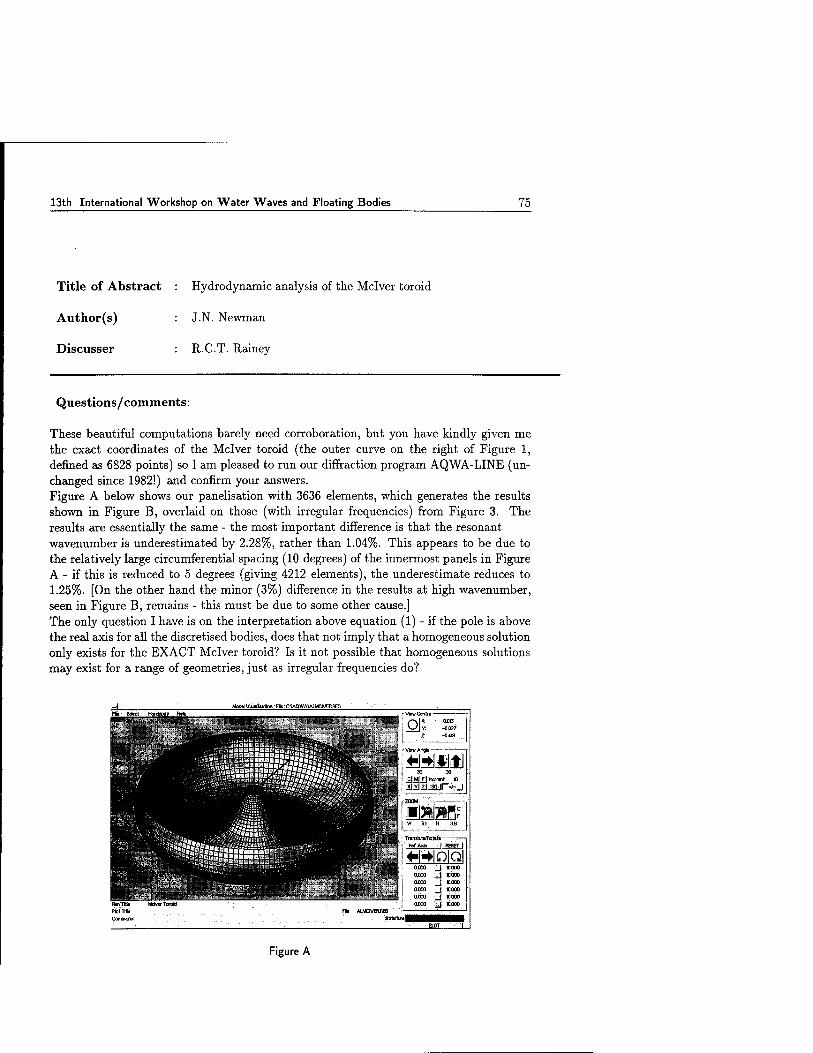
13th International Workshop on Water Waves and Floating Bodies 75
Title of Abstract : Hydrodynamic analysis of the Mclver toroid
Author(s) : J.N. Newman
Discusser : R.C.T. Rainey
Questions/comments:
These beautiful computations barely need corroboration, but you have kindly given me the exact coordinates of the Mclver toroid (the outer curve on the right of Figure 1, defined as 6828 points) so I am pleased to run our diffraction program AQWA-LINE (un- changed since 1982!) and confirm your answers. Figure A below shows our panelisation with 3636 elements, which generates the results shown in Figure B, overlaid on those (with irregular frequencies) from Figure 3. The results are essentially the same - the most important difference is that the resonant wavenumber is underestimated by 2.28%, rather than 1.04%. This appears to be due to the relatively large circumferential spacing (10 degrees) of the innermost panels in Figure A - if this is reduced to 5 degrees (giving 4212 elements), the underestimate reduces to 1.25%. [On the other hand the minor (3%) difference in the results at high wavenumber, seen in Figure B, remains - this must be due to some other cause.] The only question I have is on the interpretation above equation (1) - if the pole is above the real axis for all the discretised bodies, does that not imply that a homogeneous solution only exists for the EXACT Mclver toroid? Is it not possible that homogeneous solutions may exist for a range of geometries, just as irregular frequencies do?
0O1S -0.027 -0.4B
30 30 CJMj_FJlhcfmnt 10
■warf W 6.1 H 3.B
■ TrwMtitefflohit« ---—-— Baf Arfa '- }MHESET f
»[■»IQIQI '..id 'P-Q00
_J 10000
_J KO0° _j »000
Figure A

76 13th International Workshop on Water Waves and Floating Bodies
Figure B (Chart 1)
Figure B (Chart 2)

13th International Workshop on Water Waves and Floating Bodies 77
Author's reply:
Thank you for the compliment and confirmation. Regarding the question, I would expect that any perturbation from the exact Mclver toroid geometry would correspond to a body where no homogeneous solution or trapped wave exists. This is the premise for my assumption that, for the discretized bodies we used for computations, the pole is just above the real axis. We do not know this rigorously, of course, but it would be especially remarkable if the (already remarkable) property of the continuous family of Mclver toroids applied as well to a body of slightly different form. Empirical support for my assumption follows from the observations that, as the number of panels is increased, the trend of the hydrodynamic coefficients is consistent with the behaviour of (1) as e —>• 0.

78 13th International Workshop on Water Waves and Floating Bodies
Title of Abstract : Hydrodynamic analysis of the Mclver toroid
Author(s) : J.N. Newman
Discusser S. Zhang
Questions/comments:
Your conclusion is derived based on the linear theory. Do you expect the phenomenon you predicted can be observed in experiments? Since experiments involve all sorts of factors such as viscous effects, non-linear effects, etc. the resonance might not occur.
Author's reply:
Conventional moon pools have sharp corners at the opening and other devices which promote viscous damping; experiments indicate reduced resonance of the moon pools, over a broader bandwidth. I expect the same to be true here, although the smooth curvature and converging moon pool radius suggest that nonlinear effects may be more important than viscous damping. In any event, as indicated in my response to David Evans, I would expect to see some indication of the added-mass variations over a relatively broad band
of wavenumbers. Perhaps in addition due to the effects of viscous damping and nonlinearity, the 'spikes' of the other parameters would be more noticeable since a reduction of amplitude would
imply a broader bandwidth.

13th International Workshop on Water Waves and Floating Bodies 79
Title of Abstract : Wave pattern analysis applied to nonlinear ship wave calculations
Author(s) : H.C. Raven and H.J. Prins
Discusser : R.F. Beck
Questions/comments:
Why did you not want to apply the momentum theorem directly? Since all velocities are known numerically, it is very little extra work as compared to the linear transversal cut analysis.
Author's reply:
In principle, wave pattern analysis is an elegant method, defining the wave resistance only in terms of the waves and requiring only surface values. We had not expected drawbacks like those we experienced. In hindsight it may as a matter of fact be more straightforward to define a control volume around the hull, generate a dense grid of points on it, compute the velocity induced by all panels and integrate the momentum flux. Perhaps we'll try it soon. To what extent the result then obtained will be free of numerical errors (e.g. an effect of an imperfectly closed hull panelling) is to be found out, but the accuracy will be more easily controlled than that of hull pressure integration.

80 13th International Workshop on Water Waves and Floating Bodies
Title of Abstract : Wave pattern analysis applied to nonlinear ship wave calculations
Author(s) : H.C. Raven and H.J. Prins
Discusser : S.D. Sharma
Questions/comments:
I agree that the application of linearised analysis to a nonlinear transverse wave would produce an apparent periodic variation of wave pattern resistance with increasing dis- tance behind ship. But I am not happy about the very idea of using the less accurate computed far field when the near-field solution is available. There must be a better way of evaluating the pressure integral on the hull surface. If not, one could try to use Lagally's Theorem to compute the force on the hull sources. (Have the authors checked whether the net total source strength is zero?) The next best thing may be to do a momentum integral on a box shaped control surface quite close to the hull. If you do wish to exploit the far field, I propose using a transverse strip instead of a pair of cuts to avoid the need of a least squares analysis.
Author's reply:
A better way to integrate the pressure forces over the hull has been tried for a Dawson- type method in the past (H.C. Raven, Symp. Naval Hydrodynamics 1988). It showed that a higher order pressure integration instead of the simple summation over panels made no essential difference. Two formulations based on Lagally's theorem have then been tried, but both displayed a dependence on the hull panelling very similar to that of pressure integration. To what extent these conclusions carry over to the present nonlinear method is not sure. In any case, applying Lagally's theorem to the raised-panel form will require care but may be worth pursuing. For the momentum integral approach, see above. If we understand it correctly, the transverse strip approach means using the wave height and the longitudinal wave slope along a transverse line. It probably should display the same waviness that we found. The present least squares analysis (needed if we use more than 2 cuts) provides redundancy and permits to spread out the cuts, so it is a solution rather than the source of the problem.

13th International Workshop on Water Waves and Floating Bodies 81
Title of Abstract : Wave pattern analysis applied to nonlinear ship wave calculations
Author(s) : H.C. Raven and H.J. Prins
ERRATUM
The first formula on page 133 should read:
■q - l/2Hi sin x + l/2H2 sin x - 1/8H? cos 2x

82 13th International Workshop on Water Waves and Floating Bodies
Title of Abstract : Suppression of wave-breaking in nonlinear water wave computations
Author(s) : A.K. Subramani, R.F. Beck and W.W. Schultz
Discusser : E. van Daalen
Questions/comments:
In your abstract you state that the maximum values of the curvature (shown in Fig. 4) do not vary much with the node distribution. However, differences of the order of 30%-40%
can be observed. How does this affect the results? Also, can you explain why you did this sensitivity study anyway?
Author's reply:
Firstly, we carried out the sensitivity study because it was in keeping with the general guideline that a grid convergence analysis accompany any new numerical investigation.
On the magnitude of the differences due to the node distribution: we admit that differences of that order cannot be categorically glossed over as minor, and we thank you for the correction and, consequently, this opportunity to make an important clarification. The basis for our glossing over the differences, nevertheless, was as follows: The crossing of the threshold value prescribed by the curvature-based criterion only serves as a trigger for the activation of the local absorbing patch. Differences in the estimation of the curvature would undoubtedly be responsible for a wider "error band" in figure 3, but given the sharp rise in the nature of the curve across the threshold value and that the present threshold value is already a conservative limit, the effect of the said differences on the results would be small. For waves that already satisfy the criterion comfortably, no additional damping would result because of the differences; it is only the waves that lie near the threshold value and which would otherwise not have satisfied the criterion that may be affected by the differences. Still, while the inclusion of unnecessary damping would result in slightly different waves, it may be seen as a trade-off for being able to suppress wave-breaking
altogether.

13th International Workshop on Water Waves and Floating Bodies 83
Title of Abstract : Suppression of wave-breaking in nonlinear water wave computations
Author(s) : A.K. Subramani, R.F. Beck and W.W. Schultz
Discusser : M.W. Dingemans
Questions/comments:
1. In the presented approach, the goal seems to be suppress effects of wave-breaking in order to be able to proceed the computations. In coastal engineering wave-breaking analysis is primarily used to get an accurate estimate of wave heights.
2. In a recent paper (Dingemans, Otta and Radder, Proc. 25th ICCE, Orlando, 1996) an exact wave-breaking criterion was given which amounted to a criterion on the
curvature of the wave.
3. I can not understand the physics behind the extraction of energy due to wave-
breaking.
Author's reply:
We are intrigued by your comments, for: (a) Our goal is much the same - to obtain accurate estimates of wave heights (and also wave-resistance); it is just that most methods for computing water waves cannot provide such estimates without suppressing any wave- breaking that occurs; (b) Otta et al. (1996) - in the article that you cite - also talk (although, with little exposition) of the modelling of post-breaking behavior in a way whose "effect is to reduce the crest height and the surface steepness with an associated dissipation of energy". The physics behind the extraction of energy in our model is simple: we extract energy locally from the fluid by causing it to work against an additional, external pressure. We readily admit that the amount of energy thus extracted is not yet determined by any physical reasoning. We hope to fine-tune the actual energy dissipation associated with wave-breaking as displayed experimentally in Schultz, Huh, and Griffin, (J. FLUID MECH. 278:201-228, 1994). Lastly, as previously mentioned, there are many criteria for the incidence of wave-breaking. Thank you for bringing yours to our attention. However, we would be hard-pressed to call any of them "exact". We cannot conclusively state whether one criterion is better than the other until an exhaustive comparative study has been performed. Such a study would be useful indeed.

84 13th International Workshop on Water Waves and Floating Bodies
Title of Abstract : Suppression ofwave-breaking in nonlinear water wave computations
Author(s) : A.K. Subramani, R.F. Beck and W.W. Schultz
Discusser : H.C. Raven
Questions/comments:
Your paper mentions that you intend to apply similar techniques to steady ship wave pattern calculations. Applying an artificial pressure could work there as well, and has, if I recall correctly, been done (for 2-D submerged foils) by Coleman et al some 10 years ago. However, it appears to me that your criteria for the occurence of wave-breaking have been derived mainly for ocean waves. Do you have an idea to what extent they can be used to (near-field) ship waves, or what else should be done?
Author's reply:
We are not aware of the work by Coleman et al., but would like to find out more about what was done. Preliminary observations of steep ship waves (such as the breaking wave at the stern) in our three-dimensional calculations suggest that a similar (if not identical) geometrical, curvature-based criterion as presented in the paper may be applied to such
waves _ with an estimate for wave number, k, coming from the wavelength based on Froude number. We also reason that the actual form of the damper (the Pdamp term) would have to take into consideration forward speed effects. However, at this time, we are not sure of an appropriate form of the damper. We reason that the breaking wave at the bow shoulder (from strip theory) is similar to spray generated off the wedge wavemaker in a two-dimensional tank. In our two- dimensional calculations, we have found the suppression of spray to require more damping than that of a steep, breaking wave (a Pdamp that's about twice as large) and expect that a breaking ship wave would likewise require more damping than a breaking ocean wave, other things being equal.

13th International Workshop on Water Waves and Floating Bodies 85
Title of Abstract : Suppression of wave-breaking in nonlinear water wave computations
Author(s) : A.K. Subramani, R.F. Beck and W.W. Schultz
Discusser : S.D. Sharma
Questions/comments:
Would it not be more meaningful to use acceleration of the water particles as a criterion for impending wave-breaking? Acceleration is more "physical" than curvature, which is purely geometrical, is more read- ily available in the numerical simulation, and perhaps also easier to apply in the more general 3-D case.
Author's reply:
We agree that the local acceleration is a useful criterion and that it is readily available from fa, but do not necessarily agree that it is more physical. Certainly acceleration and crest curvature occur hand-in-hand. We recognize that an exhaustive comparative study of the various wave-breaking criteria should be performed.

86 13th International Workshop on Water Waves and Floating Bodies
Title of Abstract : Free-surface evolution at the edge of an impulsively upwelling fluid layer
Author(s) : P.A. Tyvand
Discusser : E. van Daalen
Questions/comments:
Would it be possible to check the accuracy of your small-time approximation by calcu- lating the mass and/or energy in the domain as a function of time? Also, I would like to point out that there seem to be much similarities between your problem and the impuls- ive wavemaker problem, for which small-time expansion analyses were carried out, among
others, by Lin (1984) and van Daalen (1993).
Author's reply:
It is easy to show analytically that the first-order elevation takes care of the upwelling mass flux. So there is exact mass balance to the leading order. This means that all higher-order elevations should give zero when integrated from minus to plus infinity. I have not proven this analytically, but I have checked it numerically for the second-order elevation, with high accuracy. Since the mass balance seems to be satisfied identically, mass conservation does not offer any clues to the validity of our asymptotic series. The energy balance is more difficult, because there is a singularity in the horizontal velo- city at the edge {x,y) = (0,0). But I am more concerned about the momentum balance in this upwelling model: There exists a net momentum in the — z-direction immediately after the impulsive start of an upwelling potential flow. The physical origin of this hori- zontal momentum is unclear, since there is no horizontal component in the force impulse imposed on the fluid layer from below. Let me give my opinions on the similarities between the present upwelling problem and the wavemaker problem: The surface elevations are not similar. But there is a logarithmic singularity in each case. This singularity is different because it appears at the bottom in the upwelling problem and at the free surface in the the wavemaker problem. Another difference is that the singularity appears in the horizontal velocity for upwelling, but in the vertical velocity for the wavemaker. These singularities imply that the asymptotic solution represents only an outer expansion. So an inner expansion should be found to make the solution complete. For the upwelling problem, there is no singularity in the higher-order boundary value problems. This is in contrast to the wavemaker, where the singularity influences all higher-order solutions, since it appears at the free surface.
13th International Workshop on Water Waves and Floating Bodies 87
REFERENCES
[1 ] Lin, W.-M. 1984 Nonlinear motion of the free surface near a moving body. Ph.D. thesis, Massachusetts Institute of Technology - Dept. of Ocean Engineering.
[2 ] van Daalen, E.F.G. 1993 Numerical and theoretical studies of water waves and floating bodies. Dr. thesis, Twente University.
13th International Workshop on Water Waves and Floating Bodies
Title of Abstract : Free-surface evolution at the edge of an impulsively upwelling fluid layer
Author(s) : P.A. Tyvand
Discusser : W.W. Schultz
Questions/comments:
1. Your boundary conditions are periodic, but your first-order free surface elevation is not. Can you comment on the periodic extension?
2. There still is a singularity at the bottom boundary. A more appropriate problem might release a vortex sheet at the velocity discontinuity. It would seem that this might effect the later time solutions that you calculate. Please comment.
Author's reply:
1. The periodicity is artificial, but it gives the opportunity to solve the full third-order problem exactly. In the first-order solution, however, we have an exact solution in the limit as L tends to infinity, and we do not need the periodic solution. Since there is exponential spatial decay in the first-order solution, the artificial periodicity works very well. To avoid the periodicity, the higher orders should be solved with a Fourier transform. This is not very practicable in this case, as some of the functions to be transformed do not tend to zero at infinity. As mentioned above, the conservation of horizontal momentum gives conceptual difficulties in the non-periodic case. In the periodic case the overall momentum balance is trivial.
2. The present solution seems to be legal as a mathematical solution of the inviscid irrotational upwelling problem. The discontinuity in the normal velocity along the bottom does not in itself generate any vorticity in the fluid. But there is a more severe singularity: The logarithmic singularity in the horizontal velocity at the edge. It was intended to pose a basically vertical throughflow at the bottom. However, the mathematical solution will have a horizontal flow component along the bottom, so that the upwelling flow will in fact be strongly oblique close to the edge (a:, y) = (0, —1). It is not clear to me how a vorticity generation at the edge could be formulated uniquely physically and consistently mathematically. But if we consider the fluid as viscous, we might specify zero tangential velocity along the bottom.

13th International Workshop on Water Waves and Floating Bodies 89
This may suggest a leading-order upwelling with an error-function velocity profile, describing diffusion of vorticity around x = 0 and otherwise uniform upward flow. It is far from obvious how to extend such a slightly viscous solution to higher orders, as there is no longer a velocity potential, and diffusion forbids an asymptotic Taylor expansion.

90 13th International Workshop on Water Waves and Floating Bodies
Title of Abstract : Analogies for resonances in wave diffraction problems
Author(s) : T. Utsunomiya and R. Eatock Taylor
Discusser : CM. Linton
Questions/comments:
1. You claim that the real and imaginary parts of the determinant vanish at the same value of the wavenumber. To what level of accuracy have you checked this assertion?
2. You showed a table in which you obtained the same wavenumber for trapped modes in a channel as Porter and Evans have obtained for Rayleigh-Bloch surface waves along an array of cylinders. I find this surprising, can you comment on it?
Author's reply:
1. The wavenumbers at which the imaginary part of the determinant vanish have coincided with those at which the real part at least five figures accuracy for all cases, and more accurate than six figures accuracy for most cases.
2. It is also surprising for us, since the Rayleigh-Bloch waves seem not to satisfy the same boundary conditions at their nodal lines of the modulated waves at the channel problems in which the Dirichlet or the Neumann B.C.s are applied along the straight lines. Further research is required to understand why such an agreement has been
obtained.

13th International Workshop on Water Waves and Floating Bodies 91
Title of Abstract : Analogies for resonances in wave diffraction problems
Author(s) : T. Utsunomiya and R. Eatock Taylor
ERRATUM
Equation (7) is replaced by:
B{ <i(r) r^'.r lK, l<j<N;l<r< N-l] N>2,
27V for Dirichlet B.C.),
B{(r) = 1, l<j<N;r = N;N>\, for Dirichlet B.C.).
The second table is replaced by:
(7)
Table 5 ! Trapped wavenumber ks/ir for Dirichlet boundary conditions. Mode number 1/6 2/7 3/8 4/9 5/10
1 cylinder 0.977759(a) — — — — 2 cylinders 0.248370(s) 0.977759(a) — — — 3 cylinders 0.166245(s) 0.328444(a) 0.977759(a) — — 4 cylinders 0.124830(s) 0.248370(a) 0.366671(s) 0.977759(a) — 5 cylinders 0.0999145(s) 0.199238(a) 0.296807(s) 0.388389(a) 0.977759(a)
10 cylinders 0.0499896(s) 0.296807(a)
0.0999145(a) 0.343958(s)
0.149699(s) 0.388389(a)
0.199238(a) 0.425783(s)
0.248370(s) 0.977759(a)

92 13th International Workshop on Water Waves and Floating Bodies
Title of Abstract : Experimental validation of a Rankine panel method
Author(s) : R. van 't Veer
Discusser : X.-B. Chen
Questions/comments:
1. What is exactly the approach you used to evaluate double derivatives of the double- body flow in your flat-panel-constant-source method?
2. Do you check the precision of double derivatives? (A simple way to calculate accur- ately 6 double derivatives of the double-body flow was presented by X.B. Chen and S. Malenica in the 11th IWWWFB in Hamburg, for your info.)
Author's reply:
Thank you for your interesting comment and reference to a previous workshop paper.
The approach used in SEASCAPE was:
1. calculate the second derivatives close to the hull surface using the double gradient of the Green's function, we used three different points in the direction of the normal
vector;
2. extrapolate the results to the hull surface. The approach can give reasonable results, but the accuracy is difficult to assess. Recently your approach has been implemen- ted which is indeed accurate and simple and the method wil be used in future
calculations.

13th International Workshop on Water Waves and Floating Bodies 93
Title of Abstract : Experimental validation of a Rankine panel method
Author(s) R. van 't Veer
Discusser H.C. Raven
Questions/comments:
Just a more general remark on terminology. One point is that 'Neumann-Kelvin' refers to the problem with a Neumann condition on the body and a Kelvin FSBC. A 'Neumann- Kelvin FSBC therefore does not exist, while being mentioned in many talks. In your paper 'Neumann-Kelvin' actually means that the ro-terms suppose uniform flow. It then comes as no surprise that double-body is better; but you say that including the free-surface steady potential would be still more complete. Then, look in Iwashita's paper: he also compares m-terms from double-body and Neumann- Kelvin (Fig. 7 and 8), but his NK is the one including the free surface steady potential. This illustrates the confusion that may result from imprecise shortent terminology. Your comment is not required.
Author's reply:
No comment.

94 13th International Workshop on Water Waves and Floating Bodies
Title of Abstract : A waterfall springing from unsteady flow over an uneven bottom
Author(s) : W.C. Webster and X. Zhang
Discusser : S. Grilli
Questions/comments:
I am sure you are aware of fully nonlinear potential flow calculations of plunging breaking waves during shoaling over slopes. In such cases, my calculations show that, at breaking, the horizontal velocity is very non-uniform over depth. So, I guess you might need quite a high level GN theory to model that. Also, such calculations were shown to be within 1-2% of experimental measurements at breaking. Hence, irrotational inviscid flow theory is quite good to model breaking waves before the jet impacts the free surface. (See Grilli, Svendsen, Subramanya, ASCE J. Wa- terways Port Coastal and Ocean Engineering, 1997.)
Author's reply:
The Green-Naghdi equations in our paper are an approximation of inviscid flow in a wa- terfall and we hope to extend this to a plunging breaker. Shields and Webster (1988) computed the properties of solutions and regular waves in finite water depth. These res- ults show that almost all of the global properties of the pre-breaking waves (wave height, celerity, energy, particle velocity at the crest, etc.) match extremely well, even though the exact details of the kinematics internal to these waves are not matched. We would expect the same to occur in the breaking wave problem as well. That is, we expect the total flow in the jet and its energy to be reproduced well even though we are not mirroring the details of the jet kinematics. These are the quantities we need to model the post-breaking
behavior.
Shields, J.J. and Webster, W.C, "On Direct Methods in Water Wave Theory", J. Fluid
Mech., vol. 197, pp. 171-199, Dec. 1988.

13th International Workshop on Water Waves and Floating Bodies 95
Title of Abstract : A waterfall springing from unsteady flow over an uneven bottom
Author(s) : W.C. Webster and X. Zhang
Discusser : J. Grue
Questions/comments:
At the last Workshop, 12th IWWWFB in Marseilles 1997, Professor E.O. Tuck and collab- orators presented solutions to a similar problem as yours. They used analytical solutions and conformal mapping technique, arriving at quite simple procedures to analyze the problem, and obtained then quite simple interpretation.
1. What are the differences between your and their method, and
2. What is the advantage and gain of the more involved description?
Author's reply:
The GN theory is quite different in flavor and intent from the methods presented by Tuck. For simple problems that involve regular waves or solutions, analytical techniques such as Tuck's do yield good results and these results are untainted by approximation. However, Tuck's method will be difficult to use if one wished to treat an irregular wave system shoaling over a irregular bottom, a situation that presents no difficulty for the GN method. Further, GN theory is an unsteady 3-D theory and there are no formal difficulties in extending our GN results to 3-D in order to treat to treat more complicated wave breaking phenomena. This is something that is impossible for fundamentally 2-D methods, such as with the analytical solutions and conformal mapping techniques used by Tuck.

96 13th International Workshop on Water Waves and Floating Bodies
Title of Abstract : A waterfall springing from unsteady flow over an uneven bottom
Author(s) : W.C. Webster and X. Zhang
Discusser : W.W. Schultz
Questions/comments:
If both Green-Naghdi and perturbation methods solve the Euler equations, it should be possible to compare to the mathematical model not neccesarily to experiments. In par- ticular for the example you show, the flow should be potential and both methods could be compared to the numerically exact solutions of Tuck and/or Vanden Broeck.
Author's reply:
Yes, we can and will compare our results with theirs. However, we are primarily interested in unsteady flows and Tuck and Vanden Broeck's solutions are not applicable to these
situations.

13th International Workshop on Water Waves and Floating Bodies 97
Title of Abstract : Applying the finite element method in numerically solving the two dimensional free-surface water wave equations
Author(s) : J.-H. Westhuis and Andonowati
Discusser S. Grilli
Questions/comments:
I think you obtained quite nice results with your FEM method. However, in my opin- ion, you mostly treated cases with fairly shallow water (i.e. long waves) for which the variation of the solution over depth is quite mild, and I am not so sure you would obtain as accurate and/or efficient solutions for more intermediate or deeper water cases or for waves closer to breaking, for which the variation of the solution close to the free surface may be quite large. Also, particularly in the latter case, regridding might pose more of a problem. An alternative method, recently proposed by Kennedy and Fenton, based on polynomial expansions of the solution in the vertical direction, showed very promising for long waves and might be a better alternative to FEM, if one wishes to avoid using a BEM. This so-called LPA method is similar to Green-Naghdi's method. Finally in any case, a BEM method will always be more accurate than a FEM since there is no approximation of the solution inside the domain (i.e. it is exact) and all the numerical effort can be devoted to an accurate representation of the free surface in whose neighborhood most of the variation of the solution occurs. As far as the numerical efficiency, a BEM with a di- vision in sub-regions (not difficult to implement) should combine the best of both worlds, for long domains. Several such implementations of the BEM can be found in the literature.
Author's reply:
Thank you for your comments and remarks.
1. When relative short waves are generated it might indeed be necessary to locally refine the grid in the vertical direction in order to obtain accurate results. As for the case of almost breaking waves; our present method does not deal with overturning waves, because we describe the surface as a function of the spatial variable. When the free surface is treated as a collection of panels, it is possible to treat overturning waves, but as you mention rightly, the gridding of the nodes near the overturning wave can become a difficulty. Maybe the implementation of a hybrid FEM can be of use here because then not only the potential but also the velocities are directly (i.e. without numerical differentiation) known in all nodes. As mentioned in the reply to the question of Mr. Q.W. Ma this could make the gridding easier.

98 13th International Workshop on Water Waves and Floating Bodies
2. It seems to me that the best way to establish the accuracy of a numerical code is to compare its results with carefully controlled measurements. We hope to present reliable calculations that include moving wave generators at realistic frequencies and measurements soon. Maybe it is possible to set up a series of computations using different codes, that recalculate the measurements for different accuracy demands.
3. The presented wave group calculations were compared with calculations using a do- main decomposition BEM. It was not found that the BEM domain decomposition was faster than the FEM for that particular situation. Maybe in a more general 2D (or in a 3D) setting this will not always hold, but for the moment we want to specifically focus on 2D tank-like geometry's. As with many problems the most suited approach depends on the specific require- ments and limitations of the situation. At this moment it seems that for the kind of problems we want to deal with, a FEM is the most suited approach, but if the requirements or limitations change, so might the method.

13th International Workshop on Water Waves and Floating Bodies 99
Title of Abstract : Applying the finite element method in numerically solving the two dimensional free-surface water wave equations
Author(s) : J.-H. Westhuis and Andonowati
Discusser Q.W. Ma
Questions/comments:
I am very pleased with your work, particularly about the comparison of FEM with BEM, implying that FEM may be comparitive or even more efficient. Similar comparison has been made by Wu and Eatock Taylor (1994, 1995), there are also some discussions about this issue in our representation of the last workshop. I also would like to say that if you use iterative solver instead of the direct solver, as we mentioned last year, the requirement for CPU and memory should be further reduced. You said you would implement higher order FEM in your future work. My question is that, how do you think it will be beneficial, bearing in mind that the computation of coefficients involved in high order FEM may need more effort?
Author's reply:
Thank you for your comments. The question whether to use an iterative or a direct-solver depends on the geometry of the domain on which you want to solve the equations. When a two dimensional domain requires relatively few nodes in one direction, the nodes can be numbered such that the band width of the resulting matrix is small. It is then necessary to compare the actual computational effort of using an iterative (preconditioned) solver to achieve the desired accuracy with the effort required by a direct solver. In the two dimensional situations I have been discussing in the presentation, it turned out that a direct solver that employs the symmetric and banded structure of the matrix, is the more efficient solving method. When dealing with three dimensional situations, preconditioned iterative solvers will readily be faster than direct solvers because the bandwidth of the matrix will increase dramatically. However, I do not see how an iterative solver reduces the required memory, because you would need to store an additional preconditioner in order to efficiently solve the linear system. To answer your question about the benefits of higher order FEM computations: it depends on how you increase the order of your method. The use of e.g. quadratic base functions becomes, I think, especially beneficial in three dimensional calculations, because it has

100 13th International Workshop on Water Waves and Floating Bodies
almost no effect on the number of computations in the iterative solver and allows you to use less elements to obtain comparable accuracy. The contribution of the interaction of quadratic base functions on a triangular element can be calculated numerically by approximating the integral using e.g. a Gausian quadrature formula. However, I am particularly interested in another kind of higher order FEM (a hybrid FEM) were you not only use the potential, but also the velocities as 'unknown-variables'. This seems to be a less (but not in 0{n)) efficient method, but one of the main advantages will be that no differentiation of the potential is needed to compute the velocities on the free surface and (floating) bodies. This advantage greatly reduces the demands that you put on your grid, thus making it possible to more easily deal with complex geometry's.

13th International Workshop on Water Waves and Floating Bodies 101
Title of Abstract
Author(s)
Discusser
Pressure-impulse theory for water wave impact on a structure with trapped air
D.J. Wood and D.H. Peregrine
A.A. Korobkin
Questions/comments:
Did you try another distributions of the bounce-back velocity except of uniform distribu- tion and "cos" one? (to fit the experimental data and to take realistic cavity shape into account).
Author's reply:
We have tried some very simple adaptations to the velocity profile. However, the "cos" distribution is simple and gives reasonable results.

102 13th International Workshop on Water Waves and Floating Bodies
Title of Abstract
Author(s)
Discusser
A hybrid boundary-element method for non-wall-sided bodies with or without forward speed
S. Zhang, W.-M. Lin and K. Weems
X.-B. Chen
Questions/comments:
It is well known that irregular frequencies appear in TGF method. Do you think hybrid method may still have these points?
Author's reply:
In our hybrid method, the irregular frequencies associated with the transient Green's function method used in the outer domain formulation still exist. In our method, potential formulation instead of source formulation is used. However, from our numerical tests with reasonable panel resolutions, these irregular frequency effects seems to be not evident.

13th International Workshop on Water Waves and Floating Bodies 103
Title of Abstract
Author(s)
Discusser
A hybrid boundary-element method for non-wall-sided bodies with or without forward speed
S. Zhang, W.-M. Lin and K. Weems
H. Kagemoto
Questions/comments:
Although you mentioned that the difference between the experiment and the calculation on the bending moment comes from the fact that the whipping effect is not accounted for in the calculation, no high-oscillation component caused by whipping is observed in the experiment.
Author's reply:
In fact, there is indeed high-frequency components present in the experimental measure- ment (this can be seen in a plot with an expended scale). From spectral analysis, it is found that these high-frequency components are primarily related to the first bending mode of a free-free elastic beam vibration. These results can be found in "Nonlinear Predictions of Ship Motions and Wave Loads for Structural Analysis" by Lin, et al. in Proceedings of the 16th International Conference on OMAE, Yokohama, Japan, April 1997, and in "Dynamic Loadings for Structural Analysis of Fine Form Container Ship Based on a Non-linear Large Amplitude Motions and Loads Method" by Shin, et al. in Transactions of the Society of Naval Architects and Marine Engineers, Vol. 105, 1997.

104 13th International Workshop on Water Waves and Floating Bodies
Title of Abstract
Author(s)
Discusser
A hybrid boundary-element method for non-wall-sided bodies with or without forward speed
S. Zhang, W.-M. Lin and K. Weems
M. Kashiwagi
Questions/comments:
I understand that the free-surface condition in the inner region is satisfied on the incident- wave surface but in the outer region the free-surface condition must be satisfied on z = 0 because of the use of the linearized Green function. Then there must be a gap at the patching place between the incident-wave surface and the plane of z = 0. How do you treat with this gap problem?
Author's reply:
We have two approaches to deal with this so-called 'gap' problem. One approach is to transform the physical domain under incident wave surface to a compu- tation domain with a deformed body surface and a flat free surface, and solve the problem in the computation domain and transform the results back to the physical domain. The approximation related to this approach is that the slope of the incident wave is small so that in the computation domain, Laplace's equation still holds. In this approach there is no 'gap' at the edge between the free surface and the matching surface. The second approach is to satisfy the body boundary condition and free surface boundary condition on the incident wave surface without transformation as performed in the first approach. In this approach, the gap exists. The results from our sample calculations using the first and the second approaches show no significant differences. The gap can also be teated in a similar fashion as presented by Dommermuth k Yue in
J. Fluid Mech. Vol. 178, pp. 195-219.

PROGRAMME

Sunday March 29, 1998 (lst-2nd session - STTZUXSVOgECZAAC)
10.00 - 14.00 Registration (COBBy)
12.00 -13.15 Lunch (VACJCSM'ZAAC)
13.30 -13.40 Opening {VACKSMZAAC)
First session - chairman Prof. J.A. Pinkster
13.40 - 14.05 Odd M. Faltinsen and Rong Zhao, Water entry of a wedge into a channel.
14.05 - 14.30 Tatyana Khabakhpasheva and Alexander Korobkin, One-side inequali- ties in the problem of wave impact.
14.30 - 14.55 Anil K. Subramani, Robert F. Beck and William W. Schultz, Sup- pression of wave-breaking in nonlinear water wave computations.
14.55 - 15.20 Peder A. Tyvand, Free-surface evolution at the edge of an impulsively up- welling fluid layer.
15.20 - 15.40 Break (coffee, tea)
Second session - chairman Prof. S. Sharma
15.40 - 16.05 Harry B. Bingham, Computing the Green function for linear wave-body interaction.
16.05- 16.30 Hidetsugu Iwashita, Influence of the steady flow in seakeeping of a blunt ship through the free-surface condition.
16.30 - 16.55 Tim H.J. Bunnik and Aad J. Hermans, Stability analysis for the 3D unsteady free-surface condition with raised panels.
16.55 - 17.20 Sheguang Zhang, Woei-Min Lin, Kenneth Weems and Dick K.P. Yue, A hybrid boundary-element method for non-wall-sided bodies with or without forward speed.
17.20 - 17.45 Riaan van 't Veer, Experimental validation of a Rankine panel method.
19.30 Dinner (VACKEMZAAC)
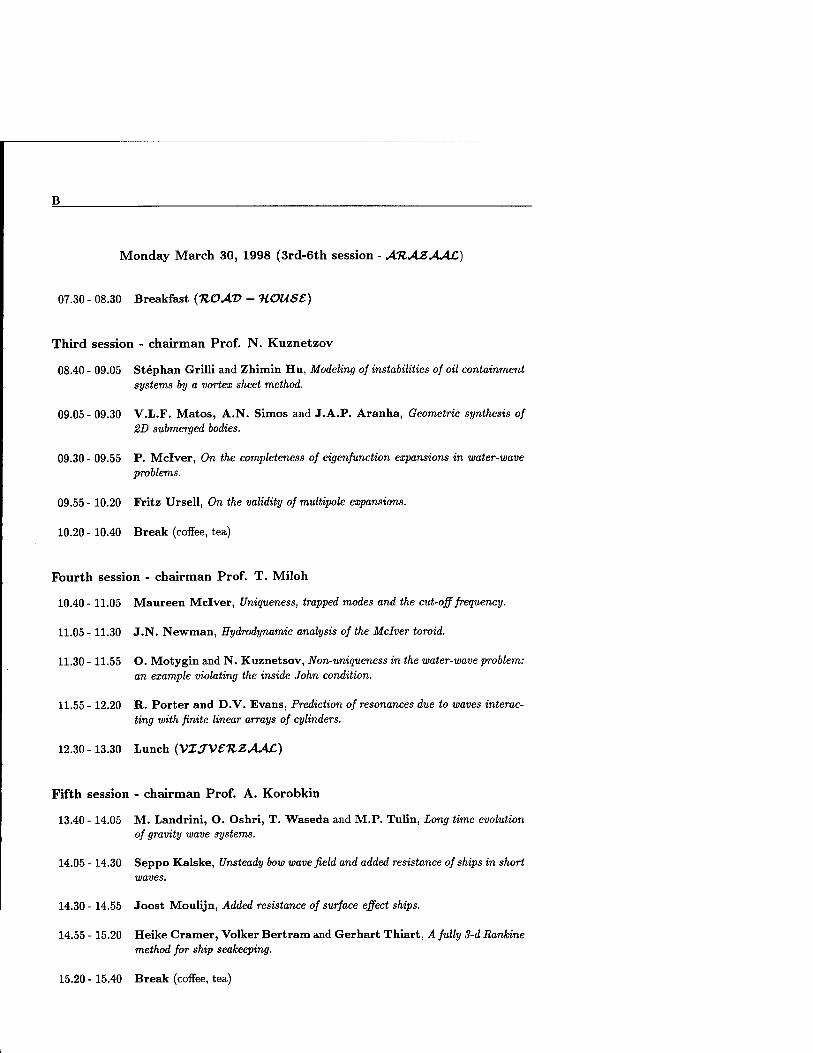
B
Monday March 30, 1998 (3rd-6th session - AHAZAAC)
07.30 - 08.30 Breakfast (HOAD - UOUSS)
Third session - chairman Prof. N. Kuznetzov
08.40 - 09.05 Stephan Grilli and Zhimin Hu, Modeling of instabilities of oil containment systems by a vortex sheet method.
09.05 - 09.30 V.L.F. Matos, A.N. Simos and J.A.P. Aranha, Geometric synthesis of 2D submerged bodies.
09.30 - 09.55 P. Mclver, On the completeness of eigenfunction expansions in water-wave problems.
09.55 - 10.20 Fritz Ursell, On the validity of multipole expansions.
10.20 - 10.40 Break (coffee, tea)
Fourth session - chairman Prof. T. Miloh
10.40- 11.05 Maureen Mclver, Uniqueness, trapped modes and the cut-off frequency.
11.05 - 11.30 J.N. Newman, Hydrodynamic analysis of the Mclver toroid.
11.30 - 11.55 O. Motygin and N. Kuznetsov, Non-uniqueness in the water-wave problem: an example violating the inside John condition.
11.55- 12.20 R. Porter and D.V. Evans, Prediction of resonances due to waves interac- ting with finite linear arrays of cylinders.
12.30 -13.30 Lunch (VXJVSTIZAAC)
Fifth session - chairman Prof. A. Korobkin
13.40 - 14.05 M. Landrini, O. Oshri, T. Waseda and M.P. Tulin, Long time evolution of gravity wave systems.
14.05 - 14.30 Seppo Kalske, Unsteady bow wave field and added resistance of ships in short waves.
14.30 - 14.55 Joost Moulijn, Added resistance of surface effect ships.
14.55 - 15.20 Heike Cramer, Volker Bertram and Gerhart Thiart, A fully 3-d Rankine method for ship seakeeping.
15.20 - 15.40 Break (coffee, tea)

Monday March 30, 1998 (3rd-6th session - AR-AZAAC)
Sixth session - chairman Dr. Volker Bertram
15.40 - 16.05 Hoyte C. Raven and Henk J. Prins, Wave pattern analysis applied to non-linear ship wave calculations.
16.05 - 16.30 Donald Danmeier, Multiple-body simulations using a higher-order panel code.
16.30-16.55 Q.W. Ma, G.X. Wu and R. Eatock Taylor, Numerical simulation of sloshing waves in a 3D tank.
16.55 - 17.20 Jaap-Harm Westhuis and Andonowati, Applying the finite element me- thod in numerically solving the two dimensional free-surface water wave equa- tions.
17.20 - 17.45 Hiroshi Kagemoto, Wave decay characteristics along a long array of cy- lindrical legs.
18.00 - 19.00 Meeting of organisers of the past and future workshops
19.30 Dinner (VXJVSHZAAC)
D
Tuesday March 31, 1998 (7th-9th session - AHAZAAC)
07.30 - 08.30 Breakfast {HOAD - UOUSt)
Seventh session - chairman Prof. J.N. Newman
08.40 - 09.05 CM. Linton, Rapidly convergent representations for free-surface Green's functions,
09.05 - 09.30 Xiao-Bo Chen and Francis Noblesse, Super Green functions for generic dispersive waves.
09.30- 09.55 Alain Clement, Computation of impulse response function using differential properties of the time-domain Green function.
09.55 - 10.20 Yonghwan Kim and P.D. Sclavounos, A finite-depth unified theory of ship motion.
10.20 - 10.40 Break (coffee, tea)
Eighth session - chairman Dr. R. Rainey
10.40- 11.05 Morton Huseby and John Grue, An experimental investigation of higher harmonic forces on a vertical cylinder in long waves.
11.05 - 11.30 Yves-Marie Scolan and S. Malenica, Experimental and numerical second order diffracted waves around an array of 4 cylinders.
11.30-11.55 C. Levi, S. Welch, E. Fontaine and M.P. Tulin, Experiments on the ringing response of an elastic cylinder in breaking wave groups.
11.55- 12.20 Peter S. Tromans and I. Ketut Suastika, Spectral response surfaces, de- signer waves and the ringing of offshore structures.
12.30 -13.30 Lunch (VXJVSHZAAC)
Ninth session - chairman Prof. B. Molin
13.40- 14.05 D. Indejtchev and Yu. Mochalova, Trapped modes in wave channel with an elastic plate on the bottom.
14.05 - 14.30 Masashi Kashiwagi, A new direct method for calculating hydroelastic deflec- tion of a very large floating structure in waves.
14.30 - 14.55 Ken Takagi, Water waves beneath a floating elastic plate.
14.55 - 15.20 M. Ohkusu and Y. Nanba, Some problems of hydroelastic behaviour of a floating thin plate in shallow water waves.
15.20 - 15.40 Break (coffee, tea)
16.00 Boat trip along the canals and lakes. Dinner on board.

Wednesday April 1, 1998 (10th-llth session - AR.AZAAC.)
07.30 - 08.30 Breakfast {HOAD - ■HOUSE)
Tenth session - chairman Prof. R. Eatock Taylor
08.40 - 09.05 Bernard Molin and Y. Stassen, A procedure to remove secularity in third- order numerical wave tanks.
09.05 - 09.30 Emmanuel Fontaine and M.P. Tulin, On the generation of wave free os- cillatory bodies and of trapped modes.
09.30 - 09.55 William C. Webster and Xinyu Zhang, A waterfall springing from unsteady flow over an uneven bottom.
09.55 - 10.20 D.J. Wood and D.H. Peregrine, Pressure-impuls theory for water wave impact on a structure with trapped air.
10.20 - 10.40 Break (coffee, tea)
Eleventh session - chairman Prof. D.V. Evans
10.40- 11.05 Bjarne Büchmann, Pierre Ferrant and Jesper Skourup, Runup on a body in waves and current. Fully non-linear and finite order calculations.
11.05 - 11.30 S.J. Cox and M.J. Cooker, The effect of wave impact in the breaker zone.
11.30 - 11.55 T. Utsunomiya and R. Eatock Taylor, Analogies for resonances in wave diffraction problems.
11.55- 12.20 Enok Palm and John Grue, On the wave field due to a moving two- dimensional, submerged body oscillating near the critical frequency.
12.20 - 12.30 Closure
12.40 - 13.30 Lunch (VXJVSHZAAC)

List of participants

List of participants
ARANHA, J.A.P. Universidade de Säo Paulo Dept. of Naval and Ocean Eng. Cx. Postal: 61548 - CEP: 05424-970 SÄO PAULO, SP Brasil Fax: +55 11 818 5717 [email protected]
BALLAST, A. MARIN P.O. Box 28 6700 AA WAGENINGEN The Netherlands Fax: +31 317 493 245 [email protected]
BECK, R.F. University of Michigan Dept. Naval Arch, and Marine Eng. 2600 Draper Road ANN ARBOR, MI 48109-2145 U.S.A. Fax: +1 313 936 8820 [email protected]
BERG, E. VAN DEN Allseas Engineering b.v. P.O. Box 5074 2600 GB DELFT The Netherlands Fax: +31 15 257 1623 [email protected]
BERTRAM, V. TUHH-IFS Lammersieth 90 D-22305 HAMBURG Germany Fax: +49 40 2984 3199 [email protected]
BUCHMANN, B. Technical University of Denmark Dept. ofHydrodyn. and Water Resources Building 115 DK-2800 LYNGBY Denmark Fax: +45 45 93 6328 [email protected]
BUNNIK, T.H.J. Delft University of Technology Faculty of Information Technology and Systems Dept. of Applied Mathematics P.O. Box 5031 2600 GA DELFT The Netherlands Fax: +31 15 278 7209 [email protected]
CHEN, X.-B. Bureau VERITAS (DTA) 17bis, Place des Reflets La Defense 2 92400 COURBEVOIE France Fax: +33 142 913 395 [email protected]
CLEMENT, A.H. ECN-LMF Div. Hydrodynamique Navale 1, Rue de la Noe B.P. 92101 44300 NANTES Cedex 3 France Fax: +33 240 372 523 [email protected]
COX, S.J. University of East Anglia School of Mathematics University Plain NORWICH NR4 7TJ United Kingdom Fax: +44 1603 25 9515 [email protected]

DAALEN, E. van MARIN P.O. Box 28 6700 AA WAGENINGEN The Netherlands Fax: +31 317 493 245 [email protected]
DANMEIER, D. M.I.T. Dept. of Ocean Engineering Room 5-324 77, Massachusetts Ave. CAMBRIDGE, MA 02139 U.S.A. Fax: +1 617 253 8125 [email protected]
DINGEMANS, M.W. Boomkensdiep 11 8303 KW EMMELOORD The Netherlands Fax: +31 527 249 601 [email protected]
EATOCK TAYLOR, R. University of Oxford Dept. of Engineering Science Parks Road OXFORD OX1 3PJ United Kingdom Fax: +44 1865 27 3010 [email protected]
EGGERMONT, M. Delft Hydraulics P.O. Box 177 2600 MH DELFT The Netherlands Fax: +31 15 285 8712 [email protected]
EVANS, D.V. University of Bristol School of Mathematics University Walk BRISTOL BS8 1TW United Kingdom Fax: +44 117 928 7999 [email protected]
FALTINSEN, O. Norwegian Univ. of Science and Technology Division of Marine Hydrodynamics N-7034 TRONDHEIM Norway Fax: +47 73 595 528 [email protected]
FERRANT, P. SIREHNA 1, Rue de la Noe P.O. Box 42105 44321 NANTES Cedex 01 France Fax: +33 240 741 736 [email protected]
FONTAINE, E. Univ. of California at Santa Barbara Ocean Engineering Laboratory 6740 Cortona Drive GOLETA, CA 93117 U.S.A. Fax: +1 805 893 4927 [email protected]
GRILLI, S. University of Rhode Island Dept. of Ocean Engineering 211 Sheets Building NARRAGANSETT, RI 02882 U.S.A. Fax: +1 401 874 6837 [email protected]

GRUE, J. University of Oslo Dept. of Mathematics P.O. Box 1053-Blindern N-0316 OSLO Norway Fax: +47 22 854 349 [email protected]
HAAS, P. DE Delft Hydraulics P.O. Box 177 2600 MH DELFT The Netherlands Fax: +31 15 285 8712 [email protected]
HERMANS, A.J. Delft University of Technology Faculty of Information Technology and Systems Dept. of Applied Mathematics P.O. Box 5031 2600 GA DELFT The Netherlands Fax: +31 15 278 7209 [email protected]
HUIJSMANS, R.H.M. MARIN P.O. Box 28 6700 AA WAGENINGEN The Netherlands Fax: +31 317 493 245 [email protected]
HUSEBY, M. University of Oslo Mechanics Division Department of Mathematics P.O. Box 1053-Blindern N-0316 OSLO Norway Fax: +47 22 854 349 [email protected]
INDEJTCHEV, D. Russian Academy of Sciences Inst. for Problems of Mech. Eng. Bol'shoy pr. 61, V.O. 199178 ST. PETERSBURG Russia Fax: +7 812 217 8614 [email protected]
IWASHITA, H. Hiroshima University Dept. of Engineering Systems 1-3-1 Kagamiyama HIGASHI-HIROSHIMA 739 Japan Fax: +81 82 422 1042 [email protected]
KAGEMOTO, H. University of Tokyo Dept. of Naval Architecture and Ocean Engineering 7-3-1 Hongo, Bunkyo-ku TOKYO 113 Japan Fax: +81 3 3815 8360 kagemoto®yuiko.nasl.t.u-tokyo.ac.jp
KALSKE, S. Helsinki University of Technology Ship Laboratory P.O. Box 4100 FIN-02015 HUT ESPOO Finland Fax: +358 9 451 3419 [email protected]
KASHIWAGI, M. Kyushu University Research Inst. for Appl. Mechanics 6-1 Kasuga-koen KASUGA-CITY, FUKUOKA 816-8580 Japan Fax: +81 92 592 4832 [email protected]

KHABAKHPASHEVA, T. Lavrentyev Inst. of Hydrodynamics Zhemchuzhnaya 14-4 630090 NOVOSIBIRSK Russia Fax: +7 383 233 1612 [email protected]
KIM, Y. M.I.T. Dept. of Ocean Engineering Room 5-329 77, Massachusetts Ave. CAMBRIDGE, MA 02139 U.SA. Fax: +1 617 253 8125 [email protected]
KOROBKIN, A.A Lavrentyev Inst. of Hydrodynamics Zhemchuzhnaya 14-4 630090 NOVOSIBIRSK Russia Fax: +7 383 233 1612 [email protected]
KUIKEN, H.K. De Sitterlaan 37 5505 AB VELDHOVEN The Netherlands
KUZNETSOV, N. Russian Academy of Sciences Lab. Math. Mod. and Wave Phen. Bol'shoy pr. 61, V.O. 199178 ST. PETERSBURG Russia Fax: +7 812 217 8614 [email protected]
LANDRINI, M. INSEAN Italian Ship Model Basin Via di Vallerano 139 00128 ROMA Italy Fax: +39 6 5070 619 [email protected]
LINTON, CM. Loughborough Univ. of Technology Dept. of Mathematical Sciences Loughborough LEICESTERSHIRE LEU 3TU United Kingdom Fax: +44 1509 223 969 [email protected]
MA, Q.W. Univ. College London Dept. of Mech. Engineering Torrington Place LONDON WC1E 7JE United Kingdom Fax: +44 171 388 0180 [email protected]
MALENICA, S. Bureau VERITAS (DTA) 17bis, Place des Reflets La Defense 2 92400 COURBEVOIE France Fax: +33 142 913 395 [email protected]
McIVER, M. Loughborough Univ. of Technology Dept. of Mathematical Sciences Loughborough LEICESTERSHIRE LEU 3TU United Kingdom Fax: +44 1509 223 969 [email protected]

McIVER, P. Loughborough Univ. of Technology Dept. of Mathematical Sciences Loughborough LEICESTERSHIRE LEU 3TU United Kingdom Fax: +44 1509 223 969 [email protected]
MILOH, T. Tel Aviv University Dept. of Fluid Mechanics and Heat Transfer RAMAT AVIV 69978 Israel Fax: +972 3 640 7334 [email protected]
MOLIN, B. ESIM Dept. Genie Mer Technopöle de Chäteau-Gombert 13451 MARSEILLE, Cedex 20 France Fax: +33 49 105 4615 [email protected]
MOTYGIN, O. Russian Academy of Sciences Lab. Math. Mod. and Wave Phen. Bol'shoy pr. 61, V.O. 199178 ST. PETERSBURG Russia Fax: +7 812 217 8614 [email protected]
MOULIJN, J. Delft University of Technology Ship Hydromechanics Laboratory Mekelweg 2 2628 CD DELFT The Netherlands Fax: +31 15 278 1836 [email protected]
NANBA, Y. Kyushu University Research Inst. for Appl. Mechanics 6-1 Kasuga-koen KASUGA-CITY, FUKUOKA 816-8580 Japan Fax: +81 92 592 4832 [email protected]
NEWMAN, J.N. M.I.T. Dept. of Ocean Engineering Room 5-324 77, Massachusetts Ave. CAMBRIDGE, MA 02139 U.S.A. Fax: +1 617 253 8125 [email protected]
NOBLESSE, F. D. Taylor Model Basin - CDNSWC 9500 Mac Arthur Blvd. WEST BETHESDA, MD 20817-5700 U.S.A. Fax: +1 301 227 4607 noblesse@dt. navy, mil
OHKUSU, M. Kyushu University Research Inst. for Appl. Mechanics 6-1 Kasuga-koen KASUGA-CITY, FUKUOKA 816-8580 Japan Fax: +81 92 592 4832 [email protected]
PALM, E. University of Oslo Dept. of Mathematics P.O. Box 1053 Blindem N-0316 OSLO Norway Fax: +47 22 854 349 [email protected]

PINKSTER, J. Delft University of Technology Faculty of Design Engineering and Production Dept. of Marine Technology Mekelweg 2 2628 CD DELFT The Netherlands Fax: +31 15 278 1836 [email protected]
PORTER, R. University of Bristol School of Mathematics University Walk BRISTOL BS8 1TW United Kingdom Fax: +44 117 928 7999 [email protected]
PRINS, H.J. MARIN P.O. Box 28 6700 AA WAGENINGEN The Netherlands Fax: +31 317 493 245 [email protected]
RAINEY, R.C.T. WS Atkins Berkshire House 171 High Holborn LONDON WC1V 7JE United Kingdom Fax: +44 171 379 8563 [email protected]
RAVEN, H.C. MARIN P.O. Box 28 6700 AA WAGENINGEN The Netherlands Fax: +31 317 493 245 [email protected]
ROM ATE, J.E. University of Twente Faculty of Mathematical Sciences Department Applied Analysis P.O. Box 217 7500 AE ENSCHEDE The Netherlands Fax: +31 53 489 4888 Email [email protected]
SCHULTZ, W.W. University of Michigan Dept. of Mechanical Engineering and Applied Mechanics 2027 Auto Lab. ANN ARBOR, MI 48109-2121 U.S.A. Fax: +1 313 764 4256 [email protected]
SCOLAN, Y.-M. ESIM Dept. Genie Mer Technopöle de Chäteau-Gombert 13451 MARSEILLE, Cedex 20 France Fax: +33 49 105 4615 [email protected]
SHARMA, S.D. Mercator University Institute of Ship Technology Building BK D-47048 DUISBURG Germany Fax: +49 203 379 2779 [email protected]
SIEREVOGEL, L.M. Delft University of Technology Faculty of Information Technology and Systems Dept. of Applied Mathematics P.O. Box 5031 2600 GA DELFT The Netherlands Fax: +31 15 278 7209 [email protected]
SKOURUP, J. ICCH Danish Hydraulic Institute Agern Alle 5 DK-2970 H0RSHOLM Denmark Fax: +45 45 762 567 [email protected]
STASSEN, Y. IFREMER P.B. 70 29280 PLOUZANE France Fax: +33 298 224 735 [email protected]
STOEP, C. van der IHC Gusto Engineering P.O. Box 11 3100 AA SCHIEDAM The Netherlands Fax: +31 10 246 6900 [email protected]
SUBRAMANI, A.K. University of Michigan Dept. Naval Arch, and Marine Eng. 2600 Draper Road ANN ARBOR, MI 48109-2145 U.S.A. Fax: +1 313 936 8820 [email protected]
TAKAGI, K. Osaka University Dept. of Naval Arch, and Ocean Eng. 2-1 Yamadaoka Suita, OSAKA 565 Japan Fax: +81 6 879 7594 takagi© naoe.eng.osaka- u .ac .jp
TANIZAWA, K. Ministry of Transport Ship Research Institute 6-38-1, Shinkawa, Mitaka TOKYO, 181 Japan Fax: +81 3 422 41 3056 [email protected]
TROMANS, P.S. Shell International P.O. Box 60 2280 AB RIJSWIJK The Netherlands Fax: +31 70 311 2085 [email protected]
TULIN, M.P. Univ. of California at Santa Barbara Ocean Engineering Laboratory 6740 Cortona Drive GOLETA, CA 93117 U.S.A. Fax: +1 805 893 4927 [email protected]
TYVAND, P.A. Agricultural Univ. of Norway Dept. of Agricultural Engineering Box 5065 N-1432 Äs Norway Fax: +47 64 948 683 [email protected]
URSELL, F. 28 Old Broadway MANCHESTER M20 3DF United Kingdom Fax: +44 161 275 4819 [email protected]

UTSUNOMIYA, T. University of Oxford Dept. of Eng. Science Parks Road OXFORD 0X1 3PJ United Kingdom Fax: +44 1865 27 3010 [email protected]
VEER, R. van 't Delft University of Technology Ship Hydromechanics Lab. Mekelweg 2 2628 CD DELFT The Netherlands Fax: +31 15 278 1836 [email protected]
WASEDA, T. Institute Pacific Research Center 2525, Correa Road HONOLULU, HI 96822 U.S.A. Fax: +1 808 956 9425 twaseda@soest .hawaii.edu
WEBSTER, W.C. University of California College of Engineering McLaughlin Hall (Room 308) BERKELEY, CA 94720-1702 U.S.A. Fax: +1 510 643 8653 [email protected]
WESTHUIS, J.-H. MARIN P.O. Box 28 6700 AA WAGENINGEN The Netherlands Fax: +31 317 493 245 [email protected]
WOOD, D.J. University of Bristol School of Mathematics University Walk BRISTOL BS8 1TW United Kingdom Fax: +44 117 928 7999 [email protected]
ZHANG, S. SAIC Ship Technology Division 134, Holiday Court (Suite 318) ANNAPOLIS, MD 21401 U.S.A. Fax: +1 410 224 2631 [email protected]
ZHANG, X. University of California Dept. of Naval Arch. & Offshore Engineering Naval Arch. Bldg. (Room 202) BERKELEY, CA 94720-1702 U.S.A. Fax: +1 510 643 8653 [email protected]
ZHAO, R. Norwegian Inst. of Science and Technology MARINTEK P.O. Box 4125 Valentinlyst N-7002 TRONDHEIM Norway Fax: +47 73 595 528 [email protected]


![13th CEPH RDMA UPDATE - OpenFabrics · 13th ANNUAL WORKSHOP 2017 CEPH RDMA UPDATE Haomai Wang, CTO [ March 28, 2017 ] XSKY](https://img.pdfslide.us/doc/110x75/5b1f11707f8b9a8a3a8c4e37/13th-ceph-rdma-update-openfabrics-13th-annual-workshop-2017-ceph-rdma-update.jpg)