Embed Size (px)
Citation preview
7/14/2019 136_en
http://slidepdf.com/reader/full/136en 1/120
RADIATIONPROTECTION
Europea n g uide lineso n ra dia tion prot ection in dent a l ra dio lo g y The safe use of radiographsin d ent a l practice
Issue N° 136

7/14/2019 136_en
http://slidepdf.com/reader/full/136en 2/120
7/14/2019 136_en
http://slidepdf.com/reader/full/136en 3/120
EUROPEAN COMMISSION
Radiation Protection 136
European guidelines on radiation protection in dental radiology
The safe use of radiographs in dental practice
Directorate-General for Energy and Transport
Directorate H — Nuclear Safety and Safeguards
Unit H.4 — Radiation Protection
2004
7/14/2019 136_en
http://slidepdf.com/reader/full/136en 4/120
This report was produced by the Victoria University of Manchester (United Kingdom) for the EuropeanCommission and represents that organisation’s views on the subject matter. These views have notbeen adopted or in any way approved by the Commission and should not be relied upon as astatement of the Commission’s views.
The European Commission does not guarantee the accuracy of the data included in this report, nor
does it accept responsibility for any use made thereof.
Europe Direct is a service to help you find answersto your questions about the European Union
New freephone number:
00 800 6 7 8 9 10 11
A great deal of additional information on the European Union is available on the Internet.It can be accessed through the Europa server (http://europa.eu.int).
Luxembourg: Office for Official Publications of the European Communities, 2004
ISBN 92-894-5958-1
© European Communities, 2004Reproduction is authorised provided the source is acknowledged.
Printed in Belgium
PRINTED ON WHITE CHLORINE-FREE PAPER
Text completed on 1 December 2003
Contract ID: B4-3040/2001/326435/MAR/C4
7/14/2019 136_en
http://slidepdf.com/reader/full/136en 5/120
PREFACE
The aim of this study is to provide a practical guide to radiation protection for
professional groups of dentists and their assistants, based upon the two relevant
Council Directives of the European Union:
· Directive 96/29/Euratom, of 13 May 1996, laying down the basic safety
standards for the protection of the health of workers and the general public
against the dangers arising from ionising radiation
· Directive 97/43/Euratom of 30 June 1997, on health protection of individuals
against the dangers of ionising radiation in relation to medical exposure
(Medical Exposures Directive).
The 1996 Basic Safety Standards Directive mentioned above ensures the protection of
workers exposed to ionising radiation, including dentists and their assistants, and of
members of the public.
Directive 97/43/Euratom provides for a high level of health protection to ionising
radiation in medical exposure. All the measures adopted in the Directive are
concerned not only with avoiding unnecessary or excessive exposure to radiation but
also with improving the quality and effectiveness of medical uses of radiation.
No exposure to X-rays can be considered completely free of risk, so the use of
radiation by dentists and their assistants implies a responsibility to ensure appropriate
protection.
In order to help Member States to implement the Directives, the Commission decided
to update and extend the technical guidelines in Radiation Protection 81 ( Radiation
protection and quality assurance in dental radiology: "The safe use of radiographs indental practice” (1995)). A contract was awarded to the University of Manchester,
UK, to carry out the study “European Guidelines on Radiation Protection in Dental
Radiology”.
The project was designed to give clear and comprehensive information on dental
radiological practices, taking into account relevant knowledge and available
technology, and give guidance on the application of radiation protection principles in
dental radiology to all individuals, including the patient and the personnel.
This document provides general guidelines on the safe use of radiographs in dental
practice. Guidelines are not a rigid constraint on clinical practice. Local variations
may be required according to healthcare practice and provision.
I am confident that the results of the study will be of help to professional groups of
dentists and their assistants, and will contribute to optimising the use of ionising
radiation in dentistry.
A. JANSSENS
Acting Head of Unit

7/14/2019 136_en
http://slidepdf.com/reader/full/136en 6/120
7/14/2019 136_en
http://slidepdf.com/reader/full/136en 7/120
3
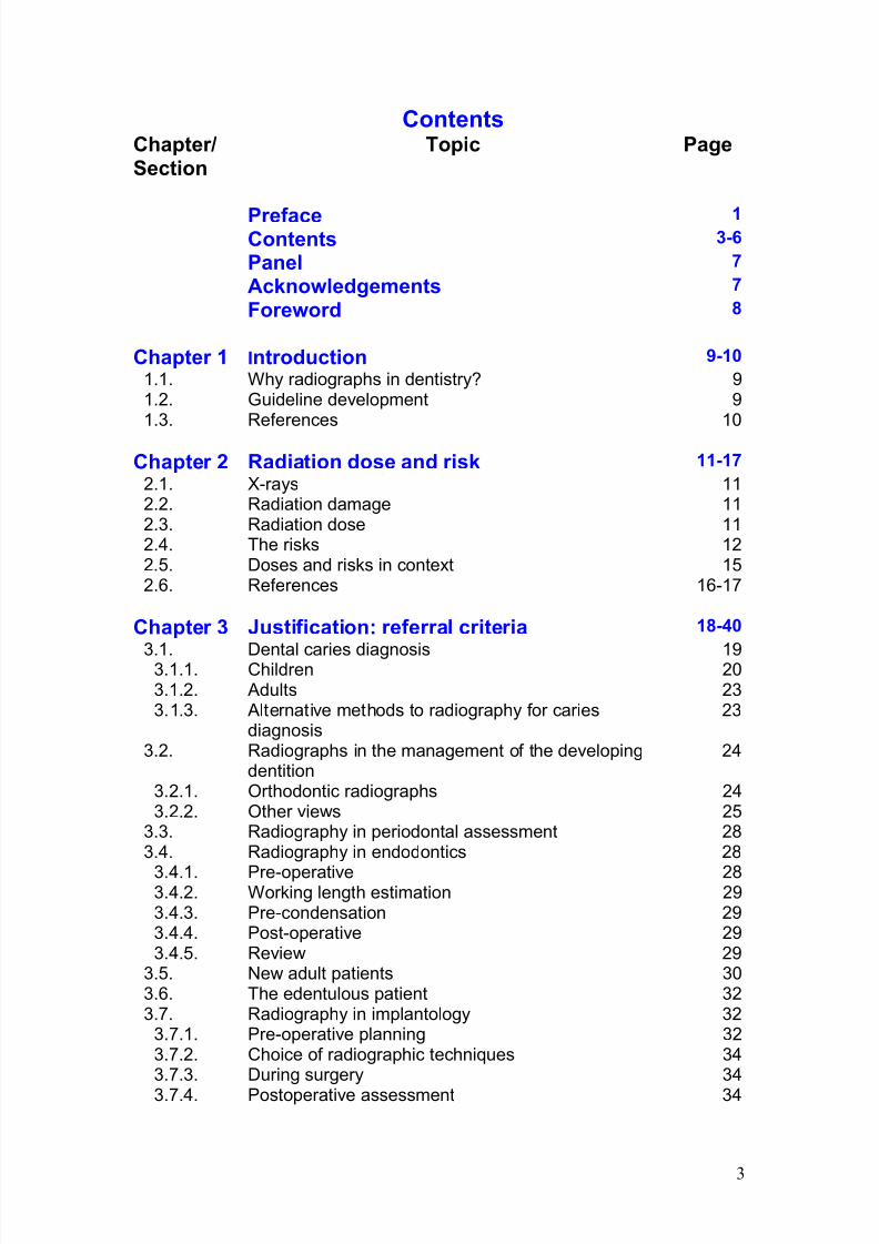
ContentsChapter/Section
Topic Page
Preface 1Contents 3-6
Panel 7
Acknowledgements 7
Foreword 8
Chapter 1 Introduction 9-10
1.1. Why radiographs in dentistry? 91.2. Guideline development 91.3. References 10
Chapter 2 Radiation dose and risk 11-17
2.1. X-rays 112.2. Radiation damage 112.3. Radiation dose 112.4. The risks 122.5. Doses and risks in context 152.6. References 16-17
Chapter 3 Justification: referral criteria 18-40
3.1. Dental caries diagnosis 193.1.1. Children 203.1.2. Adults 233.1.3. Alternative methods to radiography for caries
diagnosis23
3.2. Radiographs in the management of the developingdentition
24
3.2.1. Orthodontic radiographs 243.2.2. Other views 25
3.3. Radiography in periodontal assessment 283.4. Radiography in endodontics 28
3.4.1. Pre-operative 283.4.2. Working length estimation 293.4.3. Pre-condensation 293.4.4. Post-operative 293.4.5. Review 29
3.5. New adult patients 303.6. The edentulous patient 323.7. Radiography in implantology 32
3.7.1. Pre-operative planning 323.7.2. Choice of radiographic techniques 343.7.3. During surgery 34
3.7.4. Postoperative assessment 34
7/14/2019 136_en
http://slidepdf.com/reader/full/136en 8/120
4
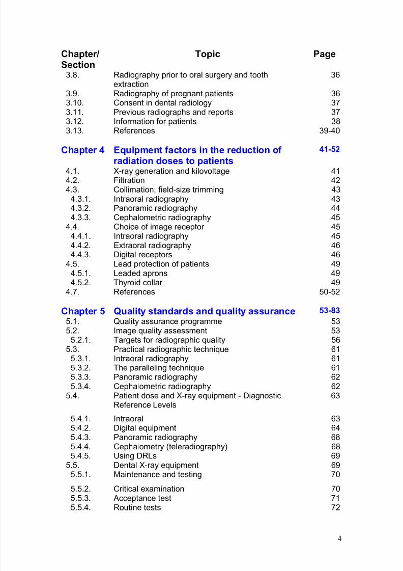
Chapter/Section
Topic Page
3.8. Radiography prior to oral surgery and toothextraction
36
3.9. Radiography of pregnant patients 36
3.10. Consent in dental radiology 373.11. Previous radiographs and reports 373.12. Information for patients 383.13. References 39-40
Chapter 4 Equipment factors in the reduction of radiation doses to patients
41-52
4.1. X-ray generation and kilovoltage 414.2. Filtration 424.3. Collimation, field-size trimming 43
4.3.1. Intraoral radiography 434.3.2. Panoramic radiography 444.3.3. Cephalometric radiography 45
4.4. Choice of image receptor 454.4.1. Intraoral radiography 454.4.2. Extraoral radiography 464.4.3. Digital receptors 46
4.5. Lead protection of patients 494.5.1. Leaded aprons 494.5.2. Thyroid collar 49
4.7. References 50-52
Chapter 5 Quality standards and quality assurance 53-83
5.1. Quality assurance programme 535.2. Image quality assessment 53
5.2.1. Targets for radiographic quality 565.3. Practical radiographic technique 61
5.3.1. Intraoral radiography 615.3.2. The paralleling technique 615.3.3. Panoramic radiography 625.3.4. Cephalometric radiography 62
5.4. Patient dose and X-ray equipment - DiagnosticReference Levels
63
5.4.1. Intraoral 635.4.2. Digital equipment 645.4.3. Panoramic radiography 685.4.4. Cephalometry (teleradiography) 685.4.5. Using DRLs 69
5.5. Dental X-ray equipment 695.5.1. Maintenance and testing 70
5.5.2. Critical examination 70
5.5.3. Acceptance test 715.5.4. Routine tests 72
7/14/2019 136_en
http://slidepdf.com/reader/full/136en 9/120
5
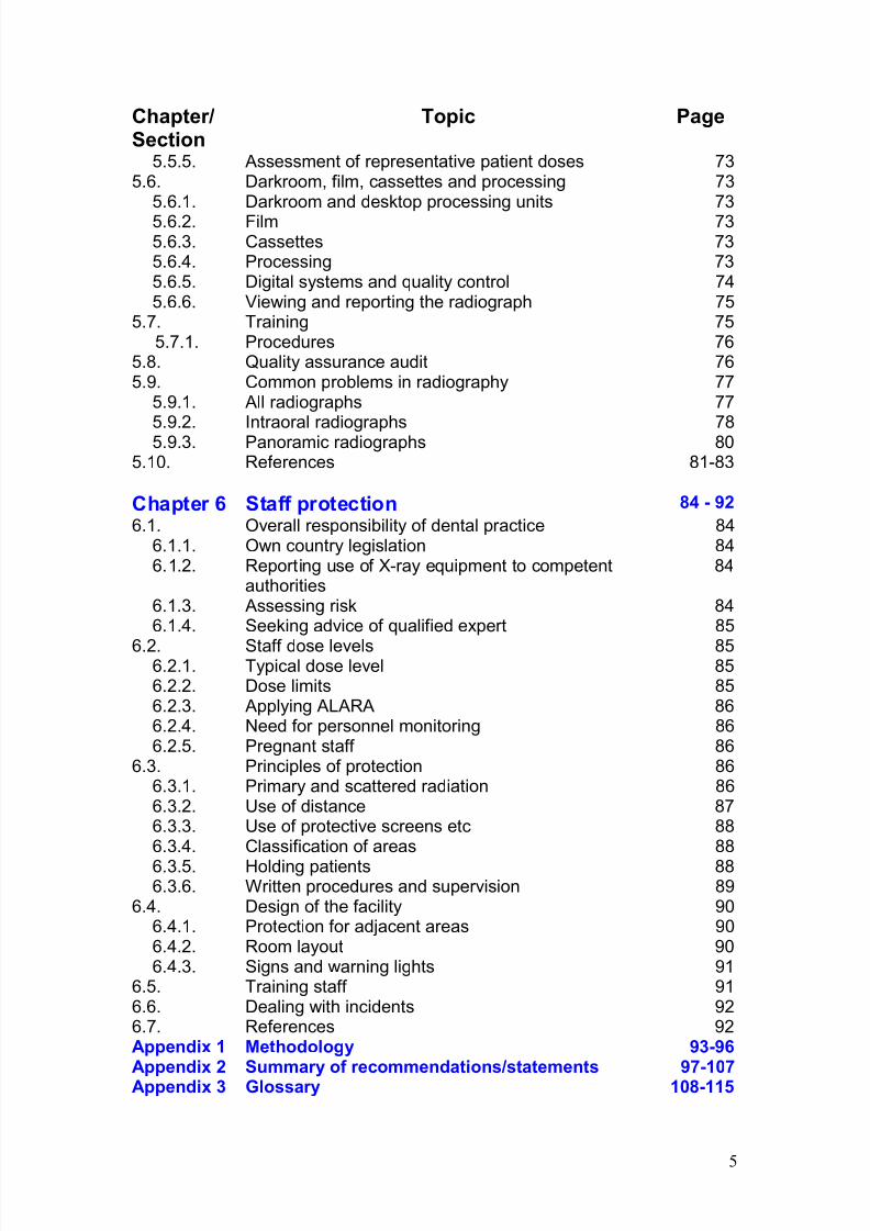
Chapter/Section
Topic Page
5.5.5. Assessment of representative patient doses 735.6. Darkroom, film, cassettes and processing 73
5.6.1. Darkroom and desktop processing units 73
5.6.2. Film 735.6.3. Cassettes 735.6.4. Processing 735.6.5. Digital systems and quality control 745.6.6. Viewing and reporting the radiograph 75
5.7. Training 755.7.1. Procedures 76
5.8. Quality assurance audit 765.9. Common problems in radiography 77
5.9.1. All radiographs 77
5.9.2. Intraoral radiographs 785.9.3. Panoramic radiographs 805.10. References 81-83
Chapter 6 Staff protection 84 - 92
6.1. Overall responsibility of dental practice 846.1.1. Own country legislation 846.1.2. Reporting use of X-ray equipment to competent
authorities84
6.1.3. Assessing risk 846.1.4. Seeking advice of qualified expert 85
6.2. Staff dose levels 856.2.1. Typical dose level 856.2.2. Dose limits 856.2.3. Applying ALARA 866.2.4. Need for personnel monitoring 866.2.5. Pregnant staff 86
6.3. Principles of protection 866.3.1. Primary and scattered radiation 866.3.2. Use of distance 876.3.3. Use of protective screens etc 886.3.4. Classification of areas 88
6.3.5. Holding patients 886.3.6. Written procedures and supervision 89
6.4. Design of the facility 906.4.1. Protection for adjacent areas 906.4.2. Room layout 906.4.3. Signs and warning lights 91
6.5. Training staff 916.6. Dealing with incidents 926.7. References 92Appendix 1 Methodology 93-96Appendix 2 Summary of recommendations/statements 97-107Appendix 3 Glossary 108-115
7/14/2019 136_en
http://slidepdf.com/reader/full/136en 10/120
6
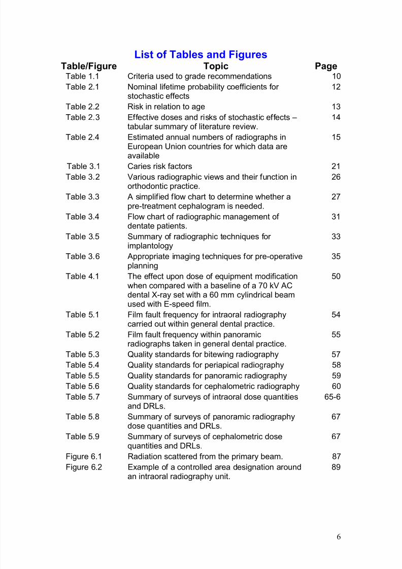
List of Tables and FiguresTable/Figure Topic Page
Table 1.1 Criteria used to grade recommendations 10
Table 2.1 Nominal lifetime probability coefficients for
stochastic effects
12
Table 2.2 Risk in relation to age 13
Table 2.3 Effective doses and risks of stochastic effects –tabular summary of literature review.
14
Table 2.4 Estimated annual numbers of radiographs inEuropean Union countries for which data areavailable
15
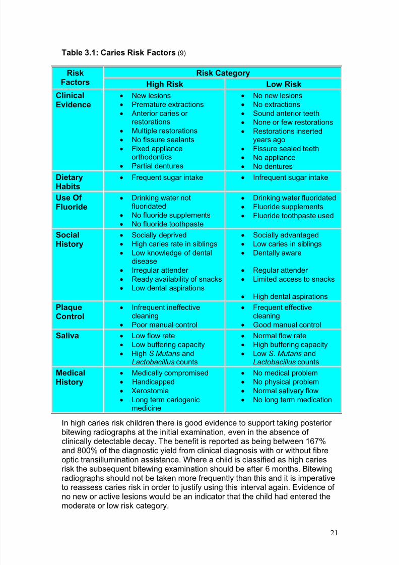
Table 3.1 Caries risk factors 21
Table 3.2 Various radiographic views and their function inorthodontic practice.
26
Table 3.3 A simplified flow chart to determine whether apre-treatment cephalogram is needed. 27
Table 3.4 Flow chart of radiographic management of dentate patients.
31
Table 3.5 Summary of radiographic techniques for implantology
33
Table 3.6 Appropriate imaging techniques for pre-operativeplanning
35
Table 4.1 The effect upon dose of equipment modificationwhen compared with a baseline of a 70 kV AC
dental X-ray set with a 60 mm cylindrical beamused with E-speed film.
50
Table 5.1 Film fault frequency for intraoral radiographycarried out within general dental practice.
54
Table 5.2 Film fault frequency within panoramicradiographs taken in general dental practice.
55
Table 5.3 Quality standards for bitewing radiography 57
Table 5.4 Quality standards for periapical radiography 58
Table 5.5 Quality standards for panoramic radiography 59
Table 5.6 Quality standards for cephalometric radiography 60
Table 5.7 Summary of surveys of intraoral dose quantitiesand DRLs.
65-6
Table 5.8 Summary of surveys of panoramic radiographydose quantities and DRLs.
67
Table 5.9 Summary of surveys of cephalometric dosequantities and DRLs.
67
Figure 6.1 Radiation scattered from the primary beam. 87
Figure 6.2 Example of a controlled area designation aroundan intraoral radiography unit.
89
7/14/2019 136_en
http://slidepdf.com/reader/full/136en 11/120
7
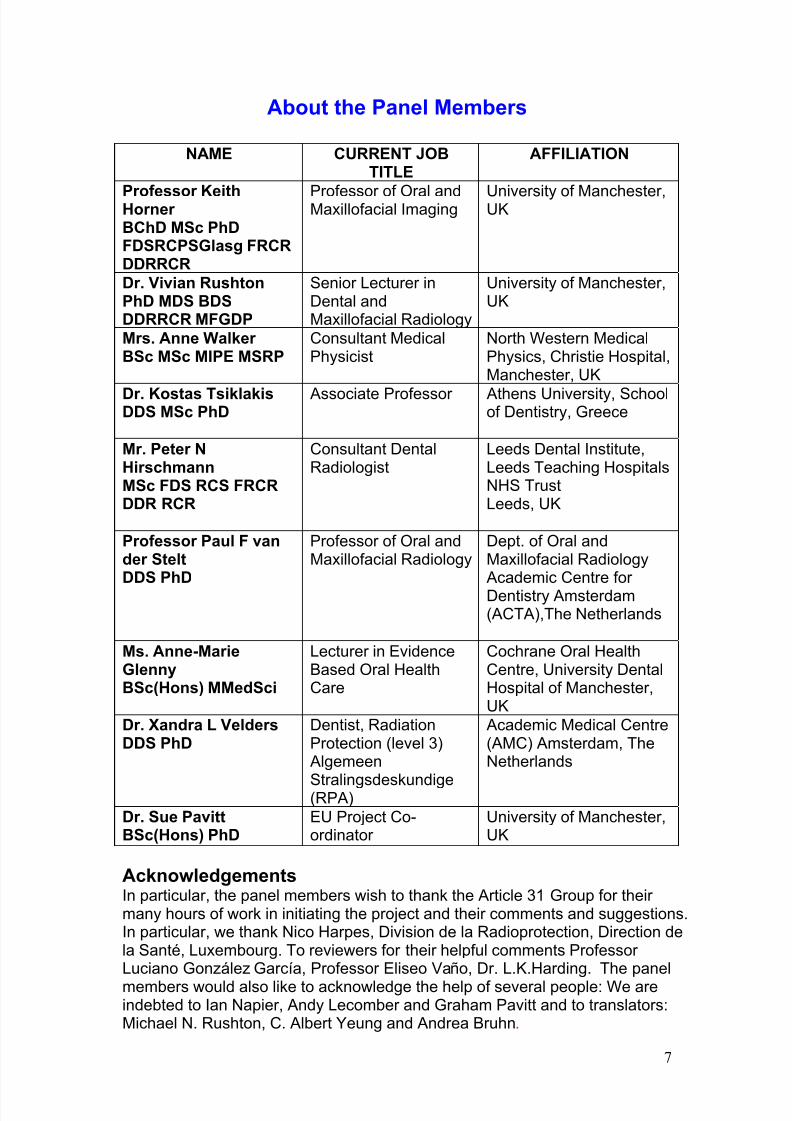
About the Panel Members
NAME CURRENT JOBTITLE
AFFILIATION
Professor KeithHorner BChD MSc PhDFDSRCPSGlasg FRCRDDRRCR
Professor of Oral andMaxillofacial Imaging University of Manchester,UK
Dr. Vivian RushtonPhD MDS BDSDDRRCR MFGDP
Senior Lecturer inDental andMaxillofacial Radiology
University of Manchester,UK
Mrs. Anne Walker BSc MSc MIPE MSRP
Consultant MedicalPhysicist
North Western MedicalPhysics, Christie Hospital,Manchester, UK
Dr. Kostas TsiklakisDDS MSc PhD
Associate Professor Athens University, Schoolof Dentistry, Greece
Mr. Peter NHirschmannMSc FDS RCS FRCRDDR RCR
Consultant DentalRadiologist
Leeds Dental Institute,Leeds Teaching HospitalsNHS TrustLeeds, UK
Professor Paul F vander SteltDDS PhD
Professor of Oral andMaxillofacial Radiology
Dept. of Oral andMaxillofacial Radiology Academic Centre for Dentistry Amsterdam(ACTA),The Netherlands
Ms. Anne-MarieGlennyBSc(Hons) MMedSci
Lecturer in EvidenceBased Oral HealthCare
Cochrane Oral HealthCentre, University DentalHospital of Manchester,UK
Dr. Xandra L VeldersDDS PhD
Dentist, RadiationProtection (level 3) Algemeen
Stralingsdeskundige(RPA)
Academic Medical Centre(AMC) Amsterdam, TheNetherlands
Dr. Sue PavittBSc(Hons) PhD
EU Project Co-ordinator
University of Manchester,UK
AcknowledgementsIn particular, the panel members wish to thank the Article 31 Group for their many hours of work in initiating the project and their comments and suggestions.In particular, we thank Nico Harpes, Division de la Radioprotection, Direction dela Santé, Luxembourg. To reviewers for their helpful comments Professor Luciano González García, Professor Eliseo Vaño, Dr. L.K.Harding. The panel
members would also like to acknowledge the help of several people: We areindebted to Ian Napier, Andy Lecomber and Graham Pavitt and to translators:Michael N. Rushton, C. Albert Yeung and Andrea Bruhn.
7/14/2019 136_en
http://slidepdf.com/reader/full/136en 12/120
8
Foreword
The radiation protection activities of the Commission of the European Union inthe medical field are based on two Council Directives:
· Directive 96/29/Euratom, of 13 May 1996, laying down the basic safetystandards for the protection of the health of workers and the generalpublic against the dangers arising from ionising radiation (EuropeanBasic Safety Standards); and
· Directive 97/43/Euratom of 30 June 1997, on health protection of individuals against the dangers of ionising radiation in relation tomedical exposure (Medical Exposures Directive).
Although doses incurred during dental examinations are in general relatively
low, dental radiology accounts for nearly one third (1)of the total number of radiological examinations in the European Union and therefore merits specificattention with regard to radiation protection.
Article 7 of the ‘Medical Exposures Directive’ stipulates that dentalpractitioners must have adequate theoretical and practical training for thepurpose of radiological practices as well as relevant competence in radiationprotection. Article 7 also requires continuing education and training after qualification.
To facilitate the implementation of this article by Member States, the
Commission decided to develop the present document, updating andextending the technical guide Radiation Protection 81 (2) in order that it takesinto account the technological developments and the new requirements of thetwo Council Directives. It is designed to give clear and comprehensiveinformation on dental radiological practices, taking into account relevantknowledge and technology available, and give guidance on the application of the radiation protection principles in dental radiology for all individuals,including both the patient and the personnel.
It is our hope that this handbook will be of help to professional groups of dentists and their assistants, and that it will contribute to optimise the use of
ionising radiation in dentistry.
Professor Keith Horner
Professor of Oral and Maxillofacial Imaging,University of Manchester, UK.
References
1. 2001. United Nations Scientific Committee on the Effects of Atomic Radiation UNSCEAR Report to theGeneral Assembly with Scientific Annex.
2. van der Stelt, P. F. 1995. Radiation protection and quality assurance in dental radiography. The safe useof radiographs in dental practice. Office for Official Pulications of the European Communities, Luxemborg.
7/14/2019 136_en
http://slidepdf.com/reader/full/136en 13/120
9
1. Introduction
The aim of this book is to provide a practical guide to radiationprotection for dentists working in a primary care setting, basedupon the two relevant Council Directives of the European Union
(EU).
· Directive 96/29/Euratom of 13 May 1996 laying down basicsafety standards for the protection of the health of workersand the general public against the dangers arising fromionising radiation.
· Directive 97/43/Euratom of 30 June 1997 on healthprotection of individuals against the dangers of ionisingradiation in relation to medical exposure.
Laws derived from these Directives exist within individual EU
States that impose specific enforceable requirements upondentists. This document sets general guidelines on goodpractice in the use of X-rays by dentists.
Guidelines are systematically developed statements to assistpractitioner and patient in decisions about appropriate healthcare for certain specific clinical circumstances (1). As thisimplies, guidelines are not a rigid constraint on clinical practice,but a concept of good practice against which the needs of theindividual patient can be considered(2).
1.1. Why radiographs in dentistry?
Radiographs are essential to dentists for:
· Diagnosis
· Treatment planning
· Monitoring treatment or lesion developmentHowever, an integral part of radiography is exposure of patients and,potentially, clinical staff to X-rays. No exposure to X-rays can be consideredcompletely free of risk, so the use of radiation by dentists is accompanied by aresponsibility to ensure appropriate protection.
1.2. Guideline development
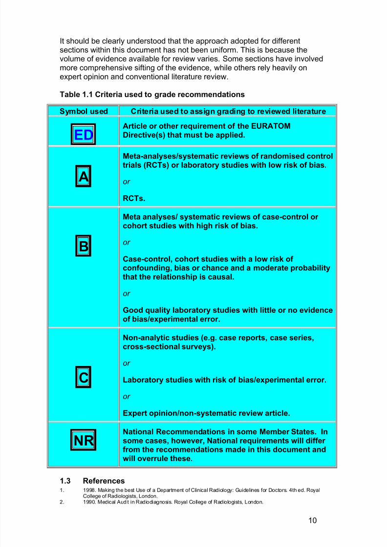
There is now widespread acceptance in medicine and dentistry that clinicalpractice should be as ‘evidence-based’ as possible. This document wasdeveloped using such an approach. The project team collected and analysedrelevant published literature, guidelines that have proved effective in the pastto arrive at recommendations that will contribute to optimisation of the use of ionising radiation in dentistry. Details of the methodology used in identifyingrelevant literature and the appraisal process are given in Table 1.1 and Appendix 1.
7/14/2019 136_en
http://slidepdf.com/reader/full/136en 14/120
10
It should be clearly understood that the approach adopted for differentsections within this document has not been uniform. This is because thevolume of evidence available for review varies. Some sections have involvedmore comprehensive sifting of the evidence, while others rely heavily onexpert opinion and conventional literature review.
Table 1.1 Criteria used to grade recommendations
Symbol used Criteria used to assign grading to reviewed literature
EDArticle or other requirement of the EURATOMDirective(s) that must be applied.
A
Meta-analyses/systematic reviews of randomised controltrials (RCTs) or laboratory studies with low risk of bias.
or
RCTs.
B
Meta analyses/ systematic reviews of case-control or cohort studies with high risk of bias.
or
Case-control, cohort studies with a low risk of confounding, bias or chance and a moderate probabilitythat the relationship is causal.
or
Good quality laboratory studies with little or no evidenceof bias/experimental error.
C
Non-analytic studies (e.g. case reports, case series,cross-sectional surveys).
or
Laboratory studies with risk of bias/experimental error.
or
Expert opinion/non-systematic review article.
NRNational Recommendations in some Member States. Insome cases, however, National requirements will differ from the recommendations made in this document andwill overrule these.
1.3 References1. 1998. Making the best Use of a Department of Clinical Radiology: Guidelines for Doctors. 4th ed. Royal
College of Radiologists, London.2. 1990. Medical Audit in Radiodiagnosis. Royal College of Radiologists, London.
7/14/2019 136_en
http://slidepdf.com/reader/full/136en 15/120
11
2 Radiation dose and risk
2.1 X-raysX-rays are a type of electromagnetic (EM) radiation. EM radiation alsoincludes visible light, radio waves, microwaves, cosmic radiation, and severalother varieties of ‘rays’. All can be considered as ‘packets’ of energy, called photons, which have wave properties, most importantly a wavelength andfrequency. X-rays are short wavelength, high frequency EM radiation. Theimportance of this is that high frequency means high energy. When X-rays hitatoms this energy can be transferred, producing ionisation of atoms.
2.2 Radiation damageWhen patients undergo X-ray examinations, millions of photons pass throughtheir bodies. These can damage any molecule by ionisation, but damage tothe DNA in the chromosomes is of particular importance. Most DNA damageis repaired immediately, but rarely a portion of a chromosome may bepermanently altered (a mutation). This may lead ultimately to the formation of a tumour. The latent period between exposure to X-rays and the clinical
diagnosis of a tumour may be many years. The risk of a tumour beingproduced by a particular X-ray dose can be estimated; therefore, knowledgeof the doses received by radiological techniques is important. While dosesand risks for dental radiology are small, a number of epidemiological studieshave provided evidence of an increased risk of brain (19, 22) , salivary gland(16, 22) and thyroid(15, 27) tumours for dental radiography.
The effects described above are believed to have no threshold radiation dosebelow which they will not occur(2). They can be considered as ‘chance’(stochastic ) effects, where the magnitude of the risk is proportional to theradiation dose. There are other known damaging effects of radiation, such as
cataract formation, skin erythema and effects on fertility, that definitely havethreshold doses below which they will not occur. These threshold doses varyin size, but all are of a magnitude far greater than those given in dentalradiography. Thus, except in extraordinary circumstances, these deterministic effects are given no further consideration.
2.3 Radiation doseThe terms ‘dose’ and ‘exposure’ are widely used but often misunderstood.‘Doses’ may be measured for particular tissues or organs (e.g. skin, eye, bonemarrow) or for the whole body, while ‘exposure’ usually refers to equipmentsettings (time, mA, kV). A commonly used measure of dose in surveys is
‘entrance dose’, measured in milligrays (mGy).This has an advantage of beingfairly easily measured by placing dosemeters on the patient’s skin. Diagnostic
The aim of this section is to describe the:
· The nature of X-rays
· The nature of radiation damage
· Radiation dose
· Radiation risk
· Dental radiography doses and risks in a lifecontext
7/14/2019 136_en
http://slidepdf.com/reader/full/136en 16/120
12
reference levels (DRLs), based upon entrance dose surveys, may be set asstandards against which X-ray equipment can be assessed as part of qualityassurance (see Chapter 5 Section 5.4 for a discussion of DRLs in dentalradiography).
In this chapter, however, radiation dose is expressed as effective dose (refer to Glossary for definition), measured in units of energy absorption per unitmass (Joules / kg) called the Sievert (more usually the microSievert, µSv,representing one millionth of a Sievert). In practice, effective dose iscalculated for any X-ray technique by measuring the energy absorption in anumber of ‘key’ organs in the body, so that the final figure is a representationof ‘whole body’ detriment. While effective dose is an impossible quantity tomeasure in vivo, it is possible to determine it from laboratory studies or computer modelling. This can then be used to estimate radiation risk.
Many studies have measured doses of radiation for dental radiography, but
only a few have estimated effective dose. There are still a number of radiographic techniques for which no published data are available and somefor which very different results have been reported. In many cases this reflectscontroversy about whether salivary glands should be given special weightingin calculation of dose. Furthermore, variation in the technical parameters of the X-ray sets and image receptors used in studies means that care should betaken when comparing dose estimations from different studies.
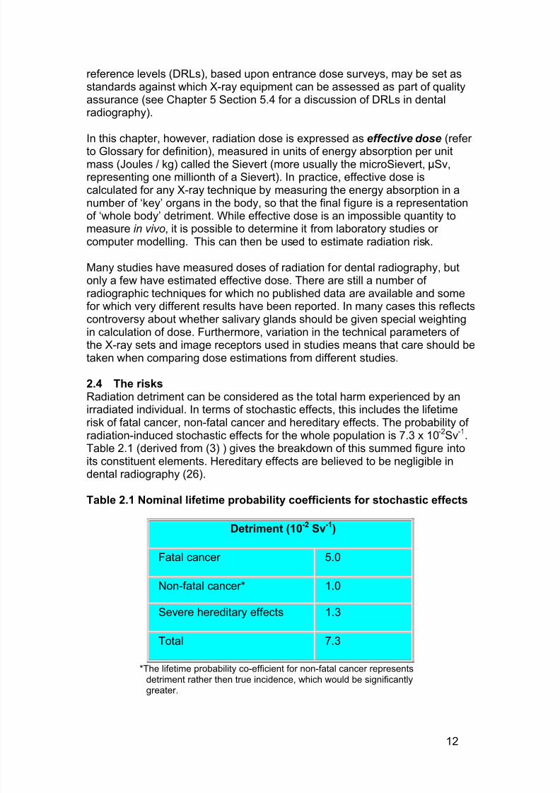
2.4 The risksRadiation detriment can be considered as the total harm experienced by anirradiated individual. In terms of stochastic effects, this includes the lifetimerisk of fatal cancer, non-fatal cancer and hereditary effects. The probability of radiation-induced stochastic effects for the whole population is 7.3 x 10⁻²Sv-1.Table 2.1 (derived from (3) ) gives the breakdown of this summed figure intoits constituent elements. Hereditary effects are believed to be negligible indental radiography (26).
Table 2.1 Nominal lifetime probability coefficients for stochastic effects
Detriment (10-2 Sv-1)
Fatal cancer 5.0
Non-fatal cancer* 1.0
Severe hereditary effects 1.3
Total 7.3
*The lifetime probability co-efficient for non-fatal cancer representsdetriment rather then true incidence, which would be significantly
greater.
7/14/2019 136_en
http://slidepdf.com/reader/full/136en 17/120
13
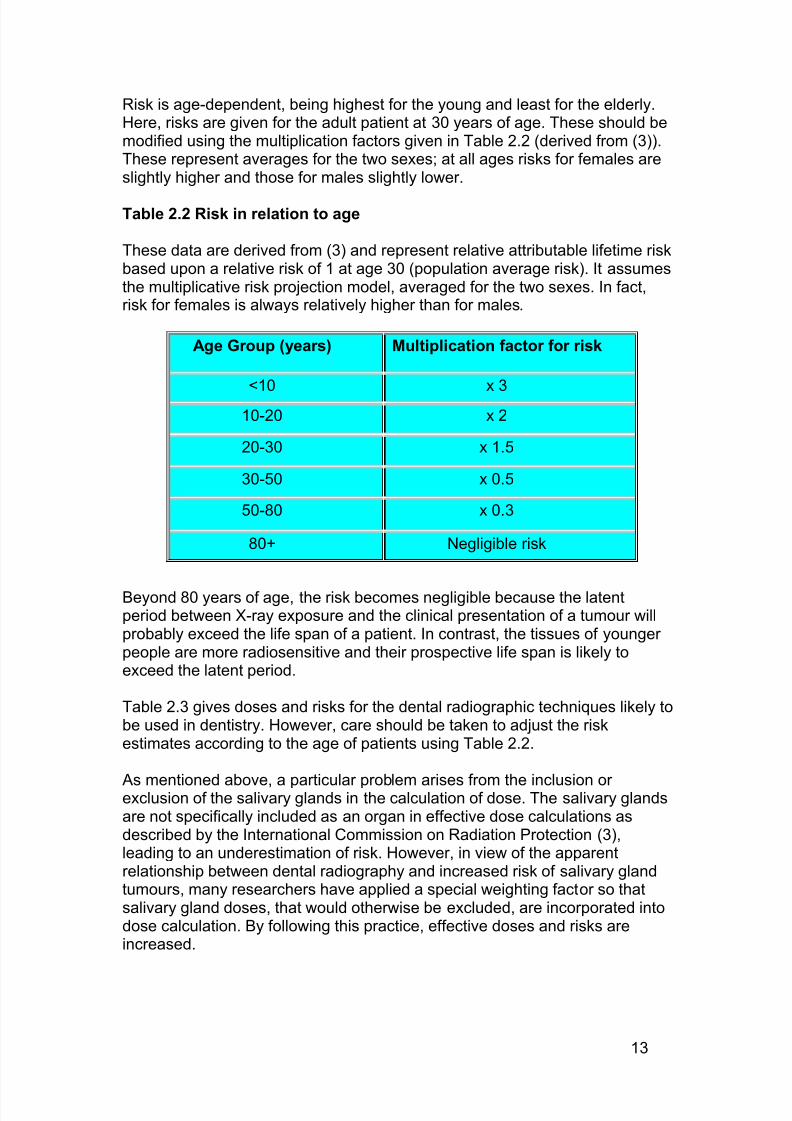
Risk is age-dependent, being highest for the young and least for the elderly.Here, risks are given for the adult patient at 30 years of age. These should bemodified using the multiplication factors given in Table 2.2 (derived from (3)).These represent averages for the two sexes; at all ages risks for females areslightly higher and those for males slightly lower.
Table 2.2 Risk in relation to age
These data are derived from (3) and represent relative attributable lifetime riskbased upon a relative risk of 1 at age 30 (population average risk). It assumesthe multiplicative risk projection model, averaged for the two sexes. In fact,risk for females is always relatively higher than for males.
Age Group (years) Multiplication factor for risk
<10 x 310-20 x 2
20-30 x 1.5
30-50 x 0.5
50-80 x 0.3
80+ Negligible risk
Beyond 80 years of age, the risk becomes negligible because the latentperiod between X-ray exposure and the clinical presentation of a tumour willprobably exceed the life span of a patient. In contrast, the tissues of younger people are more radiosensitive and their prospective life span is likely toexceed the latent period.
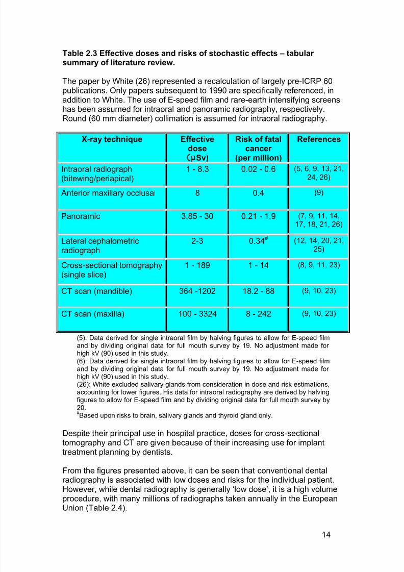
Table 2.3 gives doses and risks for the dental radiographic techniques likely tobe used in dentistry. However, care should be taken to adjust the riskestimates according to the age of patients using Table 2.2.
As mentioned above, a particular problem arises from the inclusion or exclusion of the salivary glands in the calculation of dose. The salivary glandsare not specifically included as an organ in effective dose calculations asdescribed by the International Commission on Radiation Protection (3),leading to an underestimation of risk. However, in view of the apparentrelationship between dental radiography and increased risk of salivary glandtumours, many researchers have applied a special weighting factor so thatsalivary gland doses, that would otherwise be excluded, are incorporated intodose calculation. By following this practice, effective doses and risks areincreased.
7/14/2019 136_en
http://slidepdf.com/reader/full/136en 18/120
14
Table 2.3 Effective doses and risks of stochastic effects – tabular summary of literature review.
The paper by White (26) represented a recalculation of largely pre-ICRP 60publications. Only papers subsequent to 1990 are specifically referenced, in
addition to White. The use of E-speed film and rare-earth intensifying screenshas been assumed for intraoral and panoramic radiography, respectively.Round (60 mm diameter) collimation is assumed for intraoral radiography.
X-ray technique Effectivedose(µSv)
Risk of fatalcancer
(per million)
References
Intraoral radiograph(bitewing/periapical)
1 - 8.3 0.02 - 0.6 (5, 6, 9, 13, 21,24, 26)
Anterior maxillary occlusal 8 0.4 (9)
Panoramic 3.85 - 30 0.21 - 1.9 (7, 9, 11, 14,17, 18, 21, 26)
Lateral cephalometricradiograph
2-3 0.34# (12, 14, 20, 21,25)
Cross-sectional tomography(single slice)
1 - 189 1 - 14 (8, 9, 11, 23)
CT scan (mandible) 364 -1202 18.2 - 88 (9, 10, 23)
CT scan (maxilla) 100 - 3324 8 - 242 (9, 10, 23)
(5): Data derived for single intraoral film by halving figures to allow for E-speed filmand by dividing original data for full mouth survey by 19. No adjustment made for high kV (90) used in this study.(6): Data derived for single intraoral film by halving figures to allow for E-speed filmand by dividing original data for full mouth survey by 19. No adjustment made for high kV (90) used in this study.(26): White excluded salivary glands from consideration in dose and risk estimations,accounting for lower figures. His data for intraoral radiography are derived by halving
figures to allow for E-speed film and by dividing original data for full mouth survey by20.#Based upon risks to brain, salivary glands and thyroid gland only.
Despite their principal use in hospital practice, doses for cross-sectionaltomography and CT are given because of their increasing use for implanttreatment planning by dentists.
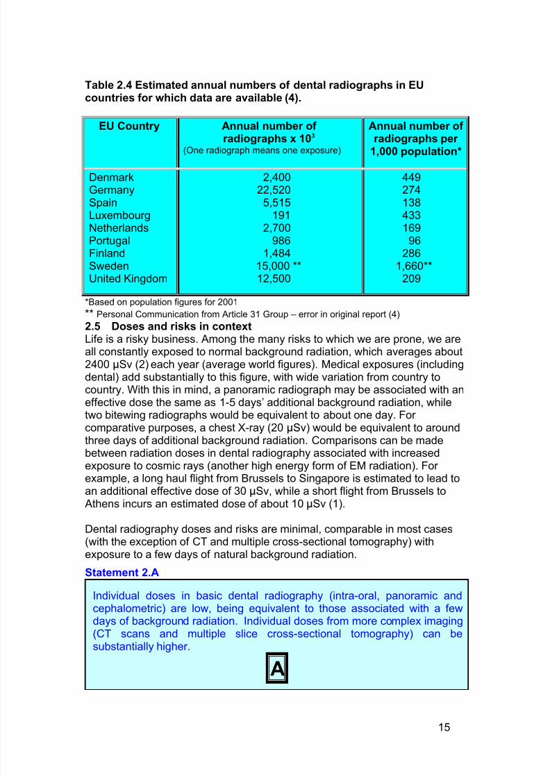
From the figures presented above, it can be seen that conventional dentalradiography is associated with low doses and risks for the individual patient.However, while dental radiography is generally ‘low dose’, it is a high volume
procedure, with many millions of radiographs taken annually in the EuropeanUnion (Table 2.4).
7/14/2019 136_en
http://slidepdf.com/reader/full/136en 19/120
15
Table 2.4 Estimated annual numbers of dental radiographs in EUcountries for which data are available (4).
EU Country Annual number of
radiographs x 103
(One radiograph means one exposure)
Annual number of
radiographs per 1,000 population*
DenmarkGermanySpainLuxembourgNetherlandsPortugalFinlandSwedenUnited Kingdom
2,40022,520
5,515191
2,700986
1,48415,000 **12,500
449274138433169
96286
1,660**209
*Based on population figures for 2001
** Personal Communication from Article 31 Group – error in original report (4)
2.5 Doses and risks in contextLife is a risky business. Among the many risks to which we are prone, we areall constantly exposed to normal background radiation, which averages about2400 µSv (2) each year (average world figures). Medical exposures (includingdental) add substantially to this figure, with wide variation from country tocountry. With this in mind, a panoramic radiograph may be associated with aneffective dose the same as 1-5 days’ additional background radiation, whiletwo bitewing radiographs would be equivalent to about one day. For comparative purposes, a chest X-ray (20 µSv) would be equivalent to aroundthree days of additional background radiation. Comparisons can be madebetween radiation doses in dental radiography associated with increasedexposure to cosmic rays (another high energy form of EM radiation). For example, a long haul flight from Brussels to Singapore is estimated to lead toan additional effective dose of 30 µSv, while a short flight from Brussels to Athens incurs an estimated dose of about 10 µSv (1).
Dental radiography doses and risks are minimal, comparable in most cases
(with the exception of CT and multiple cross-sectional tomography) withexposure to a few days of natural background radiation.
Statement 2.A
Individual doses in basic dental radiography (intra-oral, panoramic andcephalometric) are low, being equivalent to those associated with a fewdays of background radiation. Individual doses from more complex imaging(CT scans and multiple slice cross-sectional tomography) can besubstantially higher.
A
7/14/2019 136_en
http://slidepdf.com/reader/full/136en 20/120
16
Statement 2.B
2.6 References
1. 1997. European Commission. Radiation Protection 88. Recommendations for the implementation of TitleVII of the European Basic Safety Standards (BSS) Directive concerning significant increase in exposuredue to natural radiation sources. Office for Official Publications of the EC.
2. 2001. European Commission. Radiation Protection 125: Low dose ionizing radiation and cancer risk. Office
for Official Publications of the EC,Luxembourg. http://europa.eu.int/comm/environment/radprot/publications.3. 1990. ICRP Publication 60. Recommendations of the International Commission on RadiatiologicalProtection. Annal of the ICRP 21.
4. 2001. United Nations Scientific Committee on the Effects of Atomic Radiation UNSCEAR Report to theGeneral Assembly with Scientific Annex.
5. Avendanio, B., N. L. Frederiksen, B. W. Benson, and T. W. Sokolowski. 1996. Effective dose and riskassessment from detailed narrow beam radiography. Oral Surg Oral Med Oral Pathol Oral Radiol Endod82:713-9.
6. Cederberg, R. A., N. L. Frederiksen, B. W. Benson, and T. W. Sokolowski. 1997. Effect of the geometryof the intraoral position-indicating device on effective dose. Oral Surg Oral Med Oral Pathol Oral RadiolEndod 84:101-9.
7. Danforth, R. A., and D. E. Clark. 2000. Effective dose from radiation absorbed during a panoramicexamination with a new generation machine. Oral Surg Oral Med Oral Pathol Oral Radiol Endod 89:236-243.
8. Dula, K., R. Mini, J. T. Lambrecht, P. F. van der Stelt, P. Schneeberger, G. Clemens, H. Sanderink,and D. Buser. 1997. Hypothetical mortality risk associated with spiral tomography of the maxilla and
mandible prior to endosseous implant treatment. Eur J Oral Sciences 105:123-9.9. Dula, K., R. Mini, P. F. van der Stelt, and D. Buser. 2001. The radiographic assessment of implantpatients: decision-making criteria. Int J Oral Maxillofac Implants 16:80-9.
10. Frederiksen, N. L., B. W. Benson, and T. W. Sokolowski. 1995. Effective dose and risk assessment fromcomputed tomography of the maxillofacial complex. Dentomaxillofac Radiol 24:55-8.
11. Frederiksen, N. L., B. W. Benson, and T. W. Sokolowski. 1994. Effective dose and risk assessment fromfilm tomography used for dental implant diagnostics. Dentomaxillofac Radiol 23:123-7.
12. Gijbels, F., C. Bou Serhal, G. Willems, H. Bosmans, G. Sanderink, M. Persoons, and R. Jacobs.2001. Diagnostic yield of conventional and digital cephalometric images: a human cadaver study.Dentomaxillofac Radiol 30:101-5.
13. Gijbels, F., R. Jacobs, G. Sanderink, E. De Smet, B. Nowak, J. Van Dam, and D. Van Steenberghe.2002. A comparison of the effective dose from scanography with periapical radiography. DentomaxillofacRadiol 31:159-63.
14. Gori, C., F. Rossi, A. Stecco, N. Villari, and G. Zatelli. 2000. Dose evaluation and quality criteria indental radiology. Radiat Prot Dosimetry 90:225-227.
15. Hallquist, A., L. Hardell, A. Degerman, G. Wingren, and L. Boquist. 1994. Medical diagnostic andtherapeutic ionizing radiation and the risk for thyroid cancer: a case-control study. Eur J Cancer Prevention3:259-67.
16. Horn-Ross, P. L., B. M. Ljung, and M. Morrow. 1997. Environmental factors and the risk of salivary glandcancer. Epidemiology 8:414-9.
17. Lecomber, A. R., S. L. Downes, M. Mokhtari, and K. Faulkner. 2000. Optimisation of patient doses inprogrammable dental panoramic radiography. Dentomaxillofac Radiol 29:107-12.
18. Lecomber, A. R., and K. Faulkner. 1998. Conference Proceeding: Dose and risk in Dental Radiography,Luxembourg 1997. Reference Doses and Quality in Medical Imaging: What the referring practitioner and directing medical staff should know . Radiat Prot Dosimetry 80:23-25.
19. Longstreth, W. T., Jr., L. K. Dennis, V. M. McGuire, M. T. Drangsholt, and T. D. Koepsell. 1993.Epidemiology of intracranial meningioma. Cancer 72:639-48.
20. Maillie, H. D., and J. E. Gilda. 1993. Radiation-induced cancer risk in radiographic cephalometry. OralSurg Oral Med Oral Pathol 75:631-7.
21. Pasler, F. A., and H. Visser. 1999. Zahnmedizinische Radiologies, Vol. 5. Georg Thieme, Auflage.22. Preston-Martin, S., and S. C. White. 1990. Brain and salivary gland tumors related to prior dental
radiography: implications for current practice. J Am Dent Assoc 120:151-8.23. Scaf, G., A. G. Lurie, K. M. Mosier, M. L. Kantor, G. R. Ramsby, and M. L. Freedman. 1997. Dosimetry
and cost of imaging osseointegrated implants with film-based and computed tomography. Oral Surg OralMed Oral Pathol Oral Radiol Endod 83:41-8.
Individual risks in dental radiography are small but are greater in theyounger age groups (below 30 years) in which (in many Member States)dental radiography is most frequently performed.
B

7/14/2019 136_en
http://slidepdf.com/reader/full/136en 21/120
17
24. Velders, X. L., J. van Aken, and P. F. van der Stelt. 1991. Risk assessment from bitewing radiography.Dentomaxillofac Radiol 20:209-13.
25. Visser, H., T. Rodig, and K. P. Hermann. 2001. Dose reduction by direct-digital cephalometricradiography. Angle Orthodontist 71:159-63.
26. White, S. C. 1992. Assessment of radiation risk from dental radiography. Dentomaxillofac Radiol 21:118-26.
27. Wingren, G., A. Hallquist, and L. Hardell. 1997. Diagnostic X-ray exposure and female papillary thyroidcancer: a pooled analysis of two Swedish studies. Eur J Cancer Prevention 6:550-6.
7/14/2019 136_en
http://slidepdf.com/reader/full/136en 22/120
18
3 Justification: referral criteria
Any X-ray exposure entails a risk to the patient. Under normal circumstancesthe risk from dental radiography is very low. Nonetheless, it is essential thatany X-ray examination should show a net benefit to the patient, weighing thetotal potential diagnostic benefits it produces against the individual detrimentthat the exposure might cause. The efficacy, benefits and risk of availablealternative techniques having the same objective but involving no or lessexposure to X-rays should be taken into account.
Recommendation 3 A
In order that the justification process can be carried out, it is essential thatselection of appropriate radiography is based on the individual patient’shistory and a clinical examination. The ‘routine’ use of radiography on patientsbased on a generalised approach rather than individual prescription isunacceptable. A ‘routine’ or ‘screening’ examination is defined as one inwhich a radiograph is taken regardless of the presence or absence of clinicalsigns and symptoms.
Recommendation 3 B
* The statement/recommendation although not specifically stated in the European Directive is intrinsic to the process of
justification as defined by the Directive. There are no randomised controlled trials to support the recommendation; such a study
design would neither be possible nor ethical to perform.
All X-ray examinations must be justified on an individual patient basis bydemonstrating that the benefits to the patient outweigh the potentialdetriment.
The anticipated benefits are that the X-ray examination would add newinformation to aid the patient’s management.
ED
No radiographs should be selected unless a history and clinical examinationhave been performed.
‘Routine’ radiography is unacceptable practice.
ED*
The aim of this section is to:
· Explain the concept of radiographic justification
· To provide specific guidelines for a range of clinical conditions commonly encountered ingeneral dental practice
7/14/2019 136_en
http://slidepdf.com/reader/full/136en 23/120
19
Choosing the appropriate radiographic examination should also be basedupon consideration of the prevalence of diseases, their rates of progressionand the diagnostic accuracy of the imaging techniques in question.
Consulting guidelines facilitates the process of selecting radiographs. Such
guidelines, called ‘referral criteria’ or ‘selection criteria’ exist for both medicaland dental radiography. Radiographic Referral Criteria have been defined as“descriptions of clinical conditions derived from patient signs, symptoms and history that identify patients who are likely to benefit from a particular radiographic technique". As with any guideline, these are not intended to berigid constraints on clinical practice, but a concept of good practice againstwhich the needs of the individual patient can be considered.
The term ‘referral criteria’ is appropriate for medical practitioners, whereradiography is usually arranged by referral to a specialist in radiology.However, some dentists may refer patients for radiography to hospitals or
dental colleagues where they do not have the necessary equipment in their own practices. When acting as a referrer, the dentist should ensure thatadequate clinical information about the patient is provided to the person takingresponsibility for the exposure.
Recommendation 3 C
Evidence-based guidelines (9) have been devised for selection of dentalradiography. The following parts of this section are a representation of selected guidelines from that document. In isolated cases guidelines havebeen adjusted to take into account evidence in a European context.
3.1 Dental caries diagnosis
Caries risk must be assessed for all new patients and then subsequently atrecall appointment as risk factors may change in the intervening period. Byidentifying patients who are at the greatest risk of dental decay, clinicians caneffectively implement prevention techniques to maintain low caries risk status.
Caries is a multifactorial disease requiring a wide-ranging assessment of categories of risk. The important categories identified during the systematicreview (9) were:
When referring a patient for a radiographic examination, the dentist shouldsupply sufficient clinical information (based upon a history and clinicalexamination) to allow the practitioner taking clinical responsibility for the X-
ray exposure to perform the justification process.
ED
7/14/2019 136_en
http://slidepdf.com/reader/full/136en 24/120
20
· Clinical evidence of previous disease
· Dietary habits
· Social history
· Use of fluoride
· Plaque control
· Saliva· Medical history
When combined with the clinical judgement of the dentist, the use of thesefactors have been found to be an extremely efficient predictor of caries risk (6,7). Table 3.1 expands on each of the categories by sub-dividing them intohigh and low risk. Obviously, the moderate risk patient will lie in between thetwo levels.
3.1.1. Children
The early enamel lesion progresses at a relatively slow rate taking at least twoyears to progress into dentine, although progression is not inevitable (6). Earlydiagnosis of these enamel lesions is important, as with intervention lesionprogression can be slowed or reversed (6).
Posterior bitewing radiographs are an essential adjunct to clinicalexamination(9). The initial clinical examination must include an assessmentof caries risk (as high, medium or low). As outlined previously, theassessment of risk is relevant in determining when to take radiographs andtherefore must be carried out at each subsequent recall examination ensuringthat the time interval for radiography becomes patient-specific. It is feasible
that adoption of the following recommendation may lead to more radiographsbeing taken. However, this is justified as it will result in better patient care.
Recommendation 3 D
Prescription of bitewing radiographs for caries diagnosis should be basedupon caries risk assessment.
Intervals between subsequent bitewing radiographic examinations must bereassessed for each new period, as individuals can move in and out of
caries risk categories with time.
B
7/14/2019 136_en
http://slidepdf.com/reader/full/136en 25/120
21
Table 3.1: Caries Risk Factors (9)
Risk CategoryRiskFactors High Risk Low Risk
ClinicalEvidence·
New lesions· Premature extractions
· Anterior caries or restorations
· Multiple restorations
· No fissure sealants
· Fixed applianceorthodontics
· Partial dentures
·
No new lesions· No extractions
· Sound anterior teeth
· None or few restorations
· Restorations insertedyears ago
· Fissure sealed teeth
· No appliance
· No dentures
DietaryHabits
· Frequent sugar intake · Infrequent sugar intake
Use Of Fluoride
· Drinking water notfluoridated
· No fluoride supplements
· No fluoride toothpaste
· Drinking water fluoridated· Fluoride supplements
· Fluoride toothpaste used
SocialHistory
· Socially deprived
· High caries rate in siblings
· Low knowledge of dentaldisease
· Irregular attender
· Ready availability of snacks
· Low dental aspirations
· Socially advantaged
· Low caries in siblings
· Dentally aware
· Regular attender
· Limited access to snacks
· High dental aspirationsPlaqueControl
· Infrequent ineffectivecleaning
· Poor manual control
· Frequent effectivecleaning
· Good manual control
Saliva · Low flow rate
· Low buffering capacity
· High S Mutans andLactobacillus counts
· Normal flow rate
· High buffering capacity
· Low S. Mutans andLactobacillus counts
MedicalHistory
· Medically compromised
· Handicapped
· Xerostomia
· Long term cariogenicmedicine
· No medical problem
· No physical problem
· Normal salivary flow
· No long term medication
In high caries risk children there is good evidence to support taking posterior bitewing radiographs at the initial examination, even in the absence of clinically detectable decay. The benefit is reported as being between 167%and 800% of the diagnostic yield from clinical diagnosis with or without fibreoptic transillumination assistance. Where a child is classified as high cariesrisk the subsequent bitewing examination should be after 6 months. Bitewingradiographs should not be taken more frequently than this and it is imperativeto reassess caries risk in order to justify using this interval again. Evidence of
no new or active lesions would be an indicator that the child had entered themoderate or low risk category.
7/14/2019 136_en
http://slidepdf.com/reader/full/136en 26/120
22
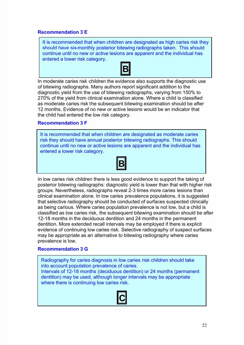
Recommendation 3 E
In moderate caries risk children the evidence also supports the diagnostic useof bitewing radiographs. Many authors report significant addition to thediagnostic yield from the use of bitewing radiographs, varying from 150% to270% of the yield from clinical examination alone. Where a child is classifiedas moderate caries risk the subsequent bitewing examination should be after 12 months. Evidence of no new or active lesions would be an indicator thatthe child had entered the low risk category.
Recommendation 3 F
In low caries risk children there is less good evidence to support the taking of posterior bitewing radiographs: diagnostic yield is lower than that with higher riskgroups. Nevertheless, radiographs reveal 2-3 times more caries lesions thanclinical examination alone. In low caries prevalence populations, it is suggestedthat selective radiography should be conducted of surfaces suspected clinicallyas being carious. Where caries population prevalence is not low, but a child isclassified as low caries risk, the subsequent bitewing examination should be after 12-18 months in the deciduous dentition and 24 months in the permanentdentition. More extended recall intervals may be employed if there is explicitevidence of continuing low caries risk. Selective radiography of suspect surfacesmay be appropriate as an alternative to bitewing radiography where caries
prevalence is low.Recommendation 3 G
3.1.2. Adults
It is recommended that when children are designated as high caries risk theyshould have six-monthly posterior bitewing radiographs taken. This shouldcontinue until no new or active lesions are apparent and the individual has
entered a lower risk category.
B
It is recommended that when children are designated as moderate cariesrisk they should have annual posterior bitewing radiographs. This shouldcontinue until no new or active lesions are apparent and the individual hasentered a lower risk category.
B
Radiography for caries diagnosis in low caries risk children should takeinto account population prevalence of caries.Intervals of 12-18 months (deciduous dentition) or 24 months (permanentdentition) may be used, although longer intervals may be appropriatewhere there is continuing low caries risk.
C
7/14/2019 136_en
http://slidepdf.com/reader/full/136en 27/120
23
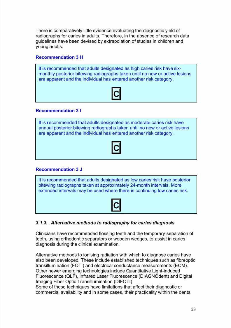
There is comparatively little evidence evaluating the diagnostic yield of radiographs for caries in adults. Therefore, in the absence of research dataguidelines have been devised by extrapolation of studies in children andyoung adults.
Recommendation 3 H
Recommendation 3 I
Recommendation 3 J
3.1.3. Alternative methods to radiography for caries diagnosis
Clinicians have recommended flossing teeth and the temporary separation of teeth, using orthodontic separators or wooden wedges, to assist in cariesdiagnosis during the clinical examination.
Alternative methods to ionising radiation with which to diagnose caries havealso been developed. These include established techniques such as fibreoptictransillumination (FOTI) and electrical conductance measurements (ECM).Other newer emerging technologies include Quantitative Light-inducedFluorescence (QLF), Infrared Laser Fluorescence (DIAGNOdent) and DigitalImaging Fiber Optic Transillumination (DIFOTI).
Some of these techniques have limitations that affect their diagnostic or commercial availability and in some cases, their practicality within the dental
It is recommended that adults designated as moderate caries risk haveannual posterior bitewing radiographs taken until no new or active lesionsare apparent and the individual has entered another risk category.
C
It is recommended that adults designated as low caries risk have posterior bitewing radiographs taken at approximately 24-month intervals. Moreextended intervals may be used where there is continuing low caries risk.
C
It is recommended that adults designated as high caries risk have six-monthly posterior bitewing radiographs taken until no new or active lesionsare apparent and the individual has entered another risk category.
C
7/14/2019 136_en
http://slidepdf.com/reader/full/136en 28/120
24
surgery. Others require further in vivo research and validation. However,several of these techniques have shown promise and may well become anaccepted part of the routine diagnostic armamentarium of the practicingclinician in the future(12, 27, 44).
Recommendation 3 K
3.2 Radiographs in the management of the developing dentition
Many children seek orthodontic treatment. When such treatment is clinicallyrequired, most children are appropriately treated at around 12-13 years of ageand will require radiographs to confirm the presence and condition of all teeth.Occasionally, there will be a need for a radiographic examination at an earlier age where there is a serious departure from normal dental development or when a child attends in pain or after trauma.
Children are subject to higher risks from X-ray exposure than are adults.Consequently the importance of justification for radiography is underlined.Basic information on radiography for orthodontics is available on the following
pages and Table 3.2. For further details, refer to the literature (29).
Usually the radiographic examination will consist of a panoramic radiograph(or right and left oblique lateral radiographs). Upper anterior occlusalradiographs are invariably required to supplement oblique lateral radiographs,but this is not the case for panoramic radiographs. Such films only provideadditional information to the panoramic film in a minority of cases (25, 29).Therefore they should be prescribed only after being justified by examiningthe panoramic radiograph.
3.2.1. Orthodontic radiographs
Radiography is needed following clinical examination in a proportion of orthodontic patients. In addition, a patient in the mixed dentition stage maywell require radiography to determine if interceptive treatment is appropriate.When previous radiographs are available, these may already contain all theinformation that the clinician needs for further management.
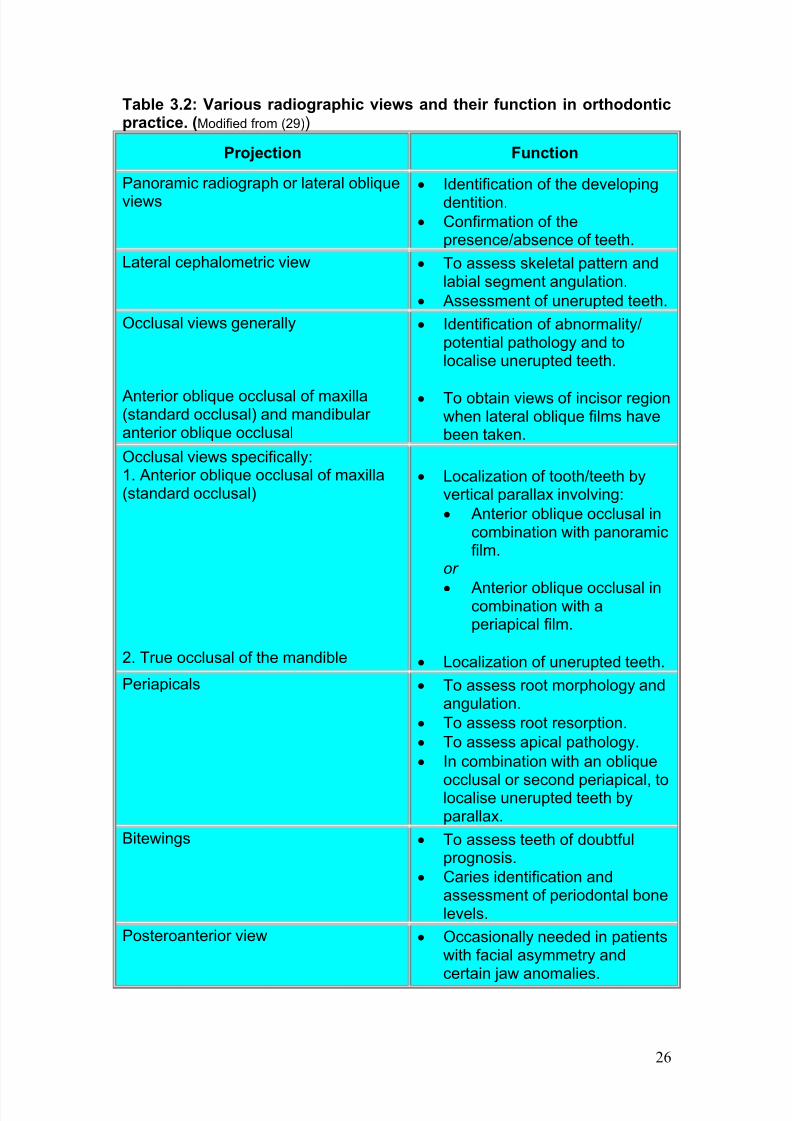
A clinical examination is necessary to ensure that the radiographs requestedwill be appropriate for the patient's specific orthodontic problem. Similarly, theneed for radiography to monitor treatment progress is dependent upon acareful clinical assessment. Table 3.2 gives a broad overview of the function
of the various radiographic projections used in orthodontic practice.
Alternative methods to using ionising radiation in caries diagnosis should beconsidered once their diagnostic validity has been clearly established.
C
7/14/2019 136_en
http://slidepdf.com/reader/full/136en 29/120
25
Various studies have confirmed that a clinical examination supplemented bystudy models is often sufficient for treatment planning (26). Furthermoreresearch using algorithms (14) and clinical indicators (28), has shown that amarked reduction in the numbers of orthodontic films is possible withoutcompromising patient treatment. From these studies, the effect of radiographs
on changing orthodontic diagnosis and treatment plans is limited ranging from16% to 37% and 4% to 20% respectively (13-15, 20).
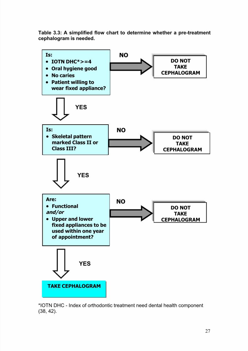
Cephalometric radiography is often requested for selected patientsundergoing orthodontic treatment. The flow chart in Table 3.3 gives a verysimplified overview of those cases that require lateral cephalometry. Inaddition, a cephalogram should be taken at:
· The end of functional appliance treatment to see the position to whichthe lowers anterior teeth have been proclined.
· The end of presurgical treatment for orthognathic cases.
· Just prior to the end of active fixed appliance treatment to assess theposition of the lower incisors.
When assessing the position of the lower incisors, the lateral cephalogram isrecommended only if the information is going to change the orthodontist'sdecision on their finishing mechanics or retention regime.
3.2.2 Other viewsThe posteroanterior (PA) view of the face/head has been advocated in casesof patients who present with facial asymmetry. The value of hand or wrist
radiography in clinical orthodontics has been questioned, as these views lackthe reliability to predict growth spurts. Similarly, radiography for temporomandibular joint dysfunction cannot be justified (22, 29) and filmstaken for this reason have been shown to have no impact on treatmentplanning (34). A more detailed description of the frequency and use of alltypes of orthodontic films can be obtained from published guidelines (29).
Recommendation 3 L
Specialist guidelines on orthodontic radiography should be consulted as anaid to justification in the management of the developing dentition in
children.
C
7/14/2019 136_en
http://slidepdf.com/reader/full/136en 30/120
26
Table 3.2: Various radiographic views and their function in orthodonticpractice. (Modified from (29))
Projection Function
Panoramic radiograph or lateral oblique
views· Identification of the developing
dentition.· Confirmation of the
presence/absence of teeth.
Lateral cephalometric view · To assess skeletal pattern andlabial segment angulation.
· Assessment of unerupted teeth.
Occlusal views generally
Anterior oblique occlusal of maxilla(standard occlusal) and mandibular anterior oblique occlusal
· Identification of abnormality/potential pathology and tolocalise unerupted teeth.
· To obtain views of incisor regionwhen lateral oblique films havebeen taken.
Occlusal views specifically:1. Anterior oblique occlusal of maxilla(standard occlusal)
2. True occlusal of the mandible
· Localization of tooth/teeth byvertical parallax involving:
· Anterior oblique occlusal incombination with panoramicfilm.
or
· Anterior oblique occlusal incombination with aperiapical film.
· Localization of unerupted teeth.
Periapicals · To assess root morphology andangulation.
· To assess root resorption.
· To assess apical pathology.
· In combination with an oblique
occlusal or second periapical, tolocalise unerupted teeth byparallax.
Bitewings · To assess teeth of doubtfulprognosis.
· Caries identification andassessment of periodontal bonelevels.
Posteroanterior view · Occasionally needed in patientswith facial asymmetry andcertain jaw anomalies.
7/14/2019 136_en
http://slidepdf.com/reader/full/136en 31/120
27
Table 3.3: A simplified flow chart to determine whether a pre-treatmentcephalogram is needed.
*IOTN DHC - Index of orthodontic treatment need dental health component(38, 42).
DO NOTTAKE
CEPHALOGRAM
YES
NO Are:
· Functionaland/or
· Upper and lowerfixed appliances to beused within one yearof appointment?
YES
TAKE CEPHALOGRAM
YES
Is:
· IOTN DHC*>=4· Oral hygiene good
· No caries
· Patient willing towear fixed appliance?
DO NOTTAKE
CEPHALOGRAM
NO
Is:
· Skeletal patternmarked Class II orClass III?
DO NOTTAKE
CEPHALOGRAM
NO
7/14/2019 136_en
http://slidepdf.com/reader/full/136en 32/120
28
3.3 Radiography in periodontal assessment
The diagnosis of periodontal diseases depends on a clinical examination.This maybe supplemented by radiographs if they provide additionalinformation, which could potentially change patient management and
prognosis. However, there is no clear evidence to support any robustrecommendations on selection of radiographs (45).
The posterior bitewing projection offers both optimal geometry and the finedetail of intraoral radiography for patients with small amounts of uniform boneloss (36). Bitewings have the additional advantage in that they may havealready been indicated for caries assessment, providing information aboutbone levels without the need for an additional radiation dose. More complexor extensive bone loss would require different imaging. Vertical bitewing,periapical and panoramic radiographs all have uses, either alone or incombination. Where periapical radiographs are used, the paralleling techniqueis indicated as this gives a better geometrical perspective on the periodontalbone than the bisecting angle technique.
Recommendation 3 M
Recommendation 3 N
3.4 Radiography in endodontics
Radiographs are essential for many aspects of endodontic treatment. It isappropriate to consider their role at the different stages of treatment(1).
3.4.1. Pre-operative A periapical radiograph provides essential information about pulp and rootcanal anatomy that cannot be obtained in any other way (30). In addition itprovides information about periradicular anatomy that may contribute totreatment planning or be essential if surgical endodontic treatment is being
considered.
Radiographs should be used in the management of periodontal disease if they are likely to provide additional information that could potentiallychange patient management and prognosis.
C
There is insufficient evidence to propose robust guidelines on choice of radiography for periodontal diagnosis and treatment, but existingradiographs e.g. bitewing radiographs taken for caries diagnosis should beused in the first instance.
C
7/14/2019 136_en
http://slidepdf.com/reader/full/136en 33/120
29
3.4.2. Working length estimationSome types of electronic apex locators are reliable at identifying the apicalconstriction and are useful for locating perforations. However, using thesedevices in certain clinical situations can result in a degree of inaccuracy. Inview of this, periapical radiography is often still required during working length
estimation. It may be necessary to take two (or more) radiographs in order todetermine the length of all the root canals in multi-rooted teeth (23).
3.4.3. Pre-condensationIf there is doubt about the integrity of the apical constriction, a checkradiograph should be taken of the master gutta-percha cone before finalcondensation/obturation.
3.4.4. Post-operative A periapical radiograph should be taken immediately following obturation asthis gives a basic assessment of the quality of the root filling and a reference
image of the periapical condition for subsequent review.
3.4.5. Review The peak incidence of healing and the peak incidence of emerging chronicapical periodontitis are seen at 1 year after treatment, with a high proportion(89%) of endodontically treated teeth demonstrating signs of healing at oneyear (35). This suggests that a one-year follow-up radiography may besufficient for small asymptomatic apical lesions. Teeth that remainsymptomatic and those with large periapical lesions may require additionalradiographic review to assess the treatment options.
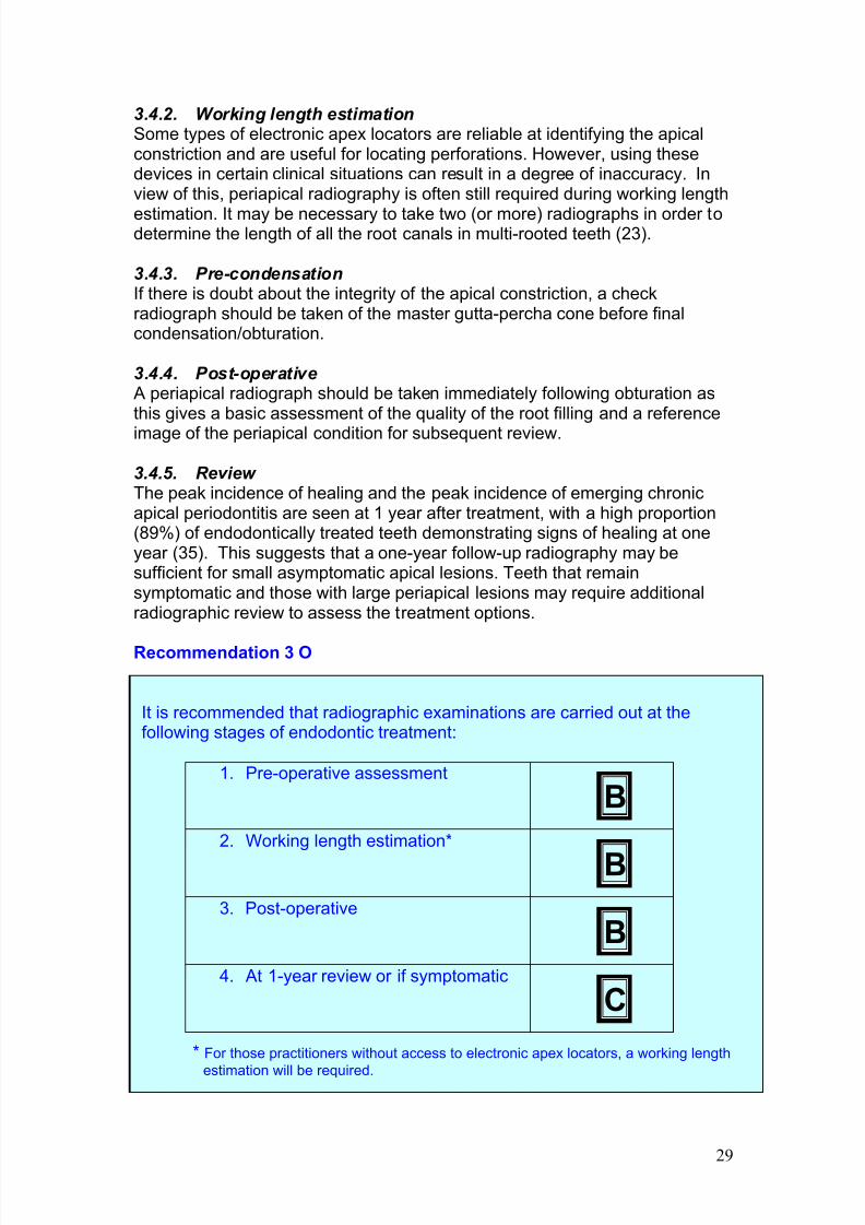
Recommendation 3 O
It is recommended that radiographic examinations are carried out at thefollowing stages of endodontic treatment:
1. Pre-operative assessment
B
2. Working length estimation*
B3. Post-operative
B
4. At 1-year review or if symptomatic
C
* For those practitioners without access to electronic apex locators, a working length
estimation will be required.
7/14/2019 136_en
http://slidepdf.com/reader/full/136en 34/120
30
3.5 New adult patients
Many dentists follow a routine practice of examining new adult patients usingpanoramic or full-mouth intraoral radiography. As discussed above, such‘routine’ practices are not acceptable (39-41).
Most evidence shows that conventional panoramic radiography has lower diagnostic accuracy for the common dental radiographic diagnostic tasks(caries diagnosis, periapical diagnosis) than intraoral (bitewing and periapical)radiography. Over and above these common tasks, routine panoramicradiography in search of asymptomatic bony lesions without clinical signs isnot justified because of the low prevalence of such abnormalities. There is no justification for review panoramic radiography at arbitrary time intervals.
Full-mouth periapical radiography can be criticised in the same way as routinepanoramic radiography. ‘Routine’ radiography will inevitably lead to
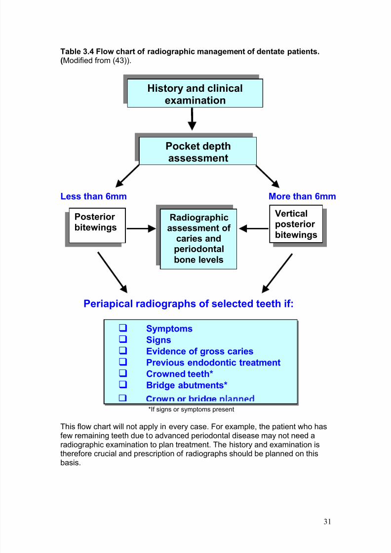
unnecessary X-ray exposure. Selected periapical radiography of new adultpatients will improve the relative risk/benefit for patients (17, 37). Takingperiapical radiographs of teeth with clinical symptoms, and of those with ahistory of endodontic therapy and deep caries as shown on bitewingradiographs, revealed 90% of periapical lesions in one research study (11).Others have also reported (19) the effectiveness of selection criteria for identification of periapical pathosis. Table 3.4 shows a flow chart (43) for theselection of radiography for new adult patients.
Recommendation 3 P
Recommendation 3 Q
For a new adult dentate patient, the choice of radiography should be basedupon history, clinical examination and an individualised prescription asillustrated in Table 3.4.
C
For a new adult dentate patient, panoramic radiography may be indicatedin a limited number of dental treatments, notably orthodontic assessmentand certain oral surgical procedures (i.e. lower third molars).
C
7/14/2019 136_en
http://slidepdf.com/reader/full/136en 35/120
31
Table 3.4 Flow chart of radiographic management of dentate patients.(Modified from (43)).
Less than 6mm More than 6mm
Periapical radiographs of selected teeth if:
*If signs or symptoms present
This flow chart will not apply in every case. For example, the patient who hasfew remaining teeth due to advanced periodontal disease may not need aradiographic examination to plan treatment. The history and examination istherefore crucial and prescription of radiographs should be planned on thisbasis.
History and clinical
examination
Pocket depthassessment
Verticalposterior bitewings
q Symptoms
q Signs
q Evidence of gross caries
q Previous endodontic treatment
q Crowned teeth*
q Bridge abutments*planned
Posterior bitewings
Radiographicassessment of
caries andperiodontalbone levels
7/14/2019 136_en
http://slidepdf.com/reader/full/136en 36/120
32
3.6. The edentulous patient
In the absence of any clinical signs or symptoms, there is no justification for any radiographic examination (18, 31, 32). The obvious exception is if implanttreatment is planned, although if treatment is extensive other more advanced
imaging (cross-sectional imaging) may well be appropriate. Where clinicalexamination identifies the possible presence of an abnormality, such as apossible retained root, then an intraoral radiograph of the site is theappropriate radiographic examination.
Recommendation 3 R
3.7. Radiography in implantology
Imaging is essential in implantology. In treatment planning, r adiographsprovide information on the quantity and quality of bone in the proposed site of implant placement. Following treatment, imaging is used to assess implantosteointegration, bone healing and to periodically review the fixture.
The review of the literature displays a paucity of evidence-based guidelineson radiography for implantology. Evidence has, in the main, been derivedfrom expert opinion and review papers (24, 33). An assessment of thesepapers revealed inconsistencies and little reliable information on thefrequency of follow-up radiography.
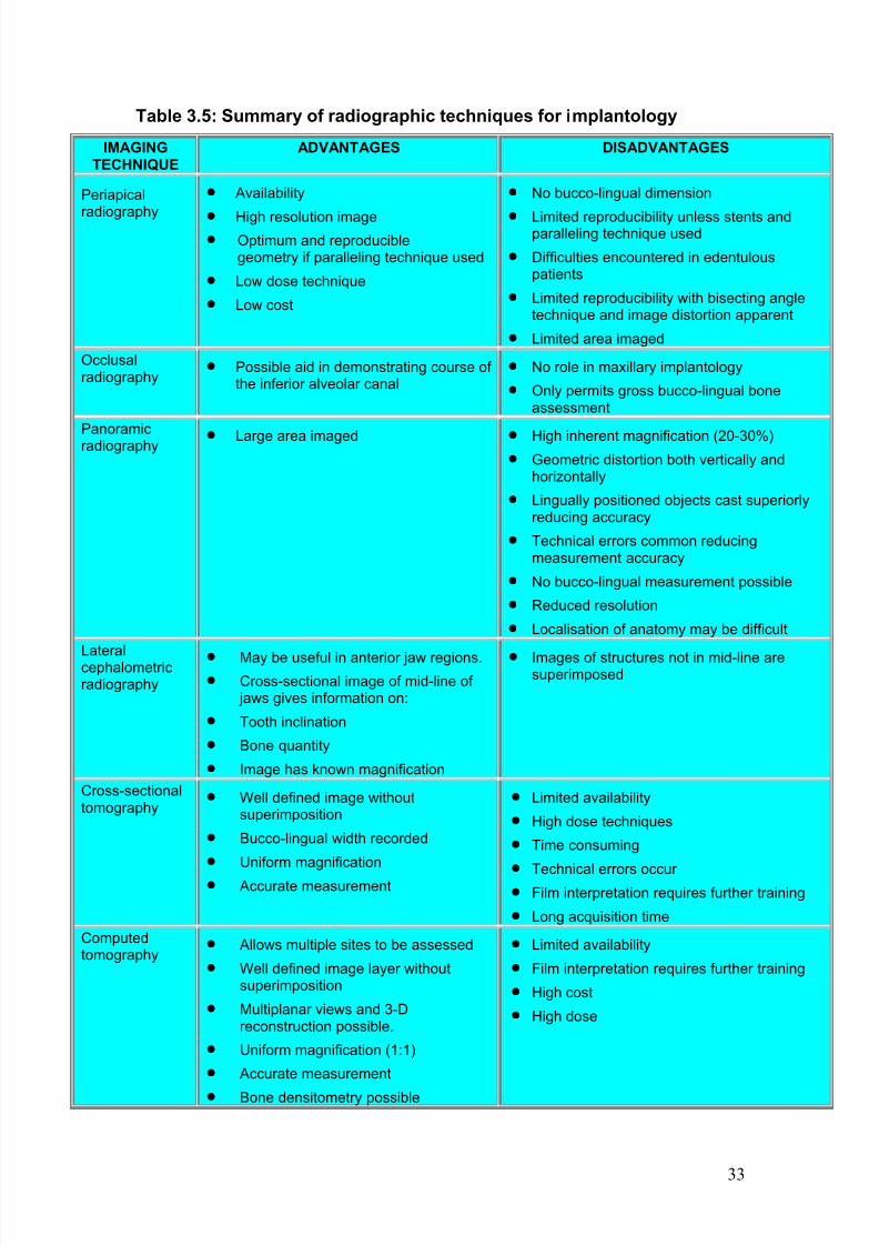
The imaging modality chosen is often a function of the treatment phase and areflection of the number of proposed implants and their position in the oralcavity. Table 3.5 gives a broad overview of the advantages anddisadvantages of the various radiographic projections used in implantology.
3.7.1. Pre-operative planning In evaluating a pre-operative site, the clinician requires information on:
· The quality and quantity of bone
· The bucco-lingual width and height of available bone
· The inclination of bony contours
· The presence of osseous undercuts
· Evidence of atypical anatomy such as enlarged marrow spaces
· Presence of pathology
·
Exact location of certain anatomic structures (i.e. the maxillary antrum,inferior alveolar canal, the mental foramen etc)
There is no justification for radiography of edentulous patients without aspecific indication such as implant treatment or clinical signs or symptoms.
B
7/14/2019 136_en
http://slidepdf.com/reader/full/136en 37/120
33
Table 3.5: Summary of radiographic techniques for implantology
IMAGINGTECHNIQUE
ADVANTAGES DISADVANTAGES
Periapical
radiography
· Availability
· High resolution image· Optimum and reproducible
geometry if paralleling technique used
· Low dose technique
· Low cost
· No bucco-lingual dimension
· Limited reproducibility unless stents andparalleling technique used
· Difficulties encountered in edentulouspatients
· Limited reproducibility with bisecting angletechnique and image distortion apparent
· Limited area imaged
Occlusalradiography
· Possible aid in demonstrating course of the inferior alveolar canal
· No role in maxillary implantology
· Only permits gross bucco-lingual boneassessment
Panoramicradiography · Large area imaged · High inherent magnification (20-30%)
· Geometric distortion both vertically andhorizontally
· Lingually positioned objects cast superiorlyreducing accuracy
· Technical errors common reducingmeasurement accuracy
· No bucco-lingual measurement possible
· Reduced resolution
· Localisation of anatomy may be difficult
Lateralcephalometricradiography
· May be useful in anterior jaw regions.
· Cross-sectional image of mid-line of jaws gives information on:
· Tooth inclination
· Bone quantity
· Image has known magnification
· Images of structures not in mid-line aresuperimposed
Cross-sectionaltomography
· Well defined image withoutsuperimposition
· Bucco-lingual width recorded
· Uniform magnification
· Accurate measurement
· Limited availability
· High dose techniques
· Time consuming
·
Technical errors occur · Film interpretation requires further training
· Long acquisition time
Computedtomography
· Allows multiple sites to be assessed
· Well defined image layer withoutsuperimposition
· Multiplanar views and 3-Dreconstruction possible.
· Uniform magnification (1:1)
· Accurate measurement
· Bone densitometry possible
· Limited availability
· Film interpretation requires further training
· High cost
· High dose
7/14/2019 136_en
http://slidepdf.com/reader/full/136en 38/120
34
With the exception of reformatted computed tomography (CT), allradiographic projections are magnified. The magnification factor must bederived and any assessments of available bone height must be calculatedhaving taken this factor into consideration. Magnification factors can bederived by use of a reference object in the same plane as the alveolus.
Periapical radiographs taken for single tooth replacement require the use of film holders and the paralleling technique for optimum geometry. Optimumgeometry is often difficult to achieve in the edentulous jaw. The magnificationfactor in panoramic radiography is particularly variable and the consensus of one expert committee (47) was to recommend that the panoramic film shouldbe augmented by tomography, either conventional or computed, in order toprovide the information necessary for optimum implant placement.
When imaging using either conventional or computed tomography to generatecross-sectional images, proposed implants sites and/or tomographic
landmarks should be identified using surgical stents consisting of metal rods,balls or radiopaque markers.
Conventional tomography is obtained either from dedicated softwareincorporated into panoramic equipment or from specifically designed X-raymachines for implantology. The latter comprises multimodal systems usingnarrow beam radiography and spiral tomography. In the past CT scanning hasbeen restricted to general hospital facilities, however smaller dedicated headand neck CT imaging equipment is becoming more commonplace. Spiral CTtechniques benefit from shorter scanning times and improved accuracy.
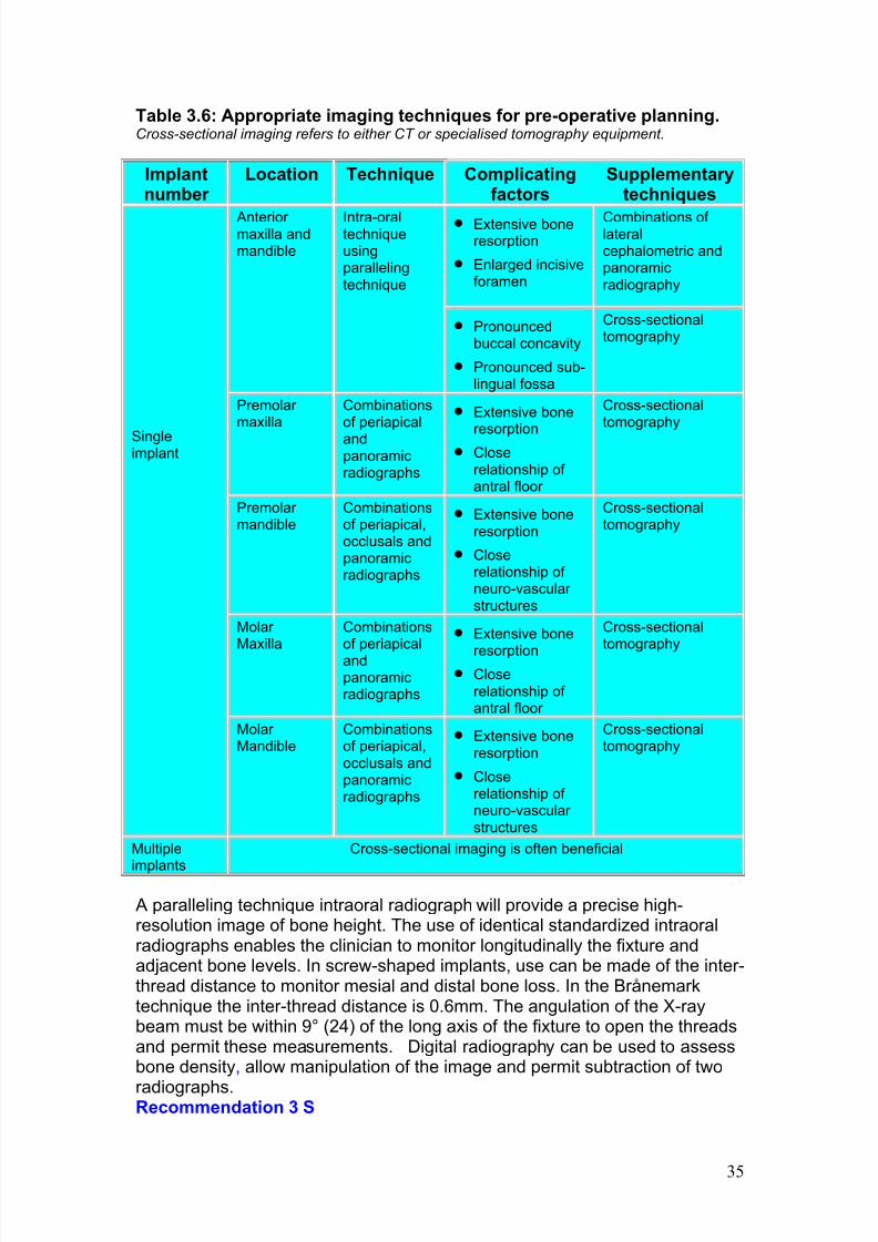
3.7.2. Choice of radiographic techniquesThe number of implants and their proposed position in the oral cavity are oftenthe main factors dictating the choice of imaging technique. A proportion of patients need advanced imaging especially in cases involving bone grafts andin those in which there are multiple potential implant sites. In these cases CThas been recommended (47). Table 3.6 details the range of imaging methodsfor pre-operative planning in various parts of the oral cavity.
3.7.3. During Surgery If any radiography is needed then periapical radiographs are readily available
and use of digital imaging should be considered which offers the benefits of 'real-time’ imaging.
3.7.4. Postoperative assessment Radiography has been recommended to evaluate the implant post-operatively. The frequency and timing of review radiographs appears to bepurely subjective. During the healing phase, radiography would obviouslyneeded if the patient has clinical symptoms. If not, the next radiographicreview should occur at 12 months and is considered essential to assessmarginal bone levels. Subsequent review intervals range from annual reviewsto once every three years. More frequent radiography is obviously needed if
the patient is symptomatic.
7/14/2019 136_en
http://slidepdf.com/reader/full/136en 39/120
35
Table 3.6: Appropriate imaging techniques for pre-operative planning.Cross-sectional imaging refers to either CT or specialised tomography equipment.
Implantnumber
Location Technique Complicatingfactors
Supplementarytechniques
· Extensive boneresorption
· Enlarged incisiveforamen
Combinations of lateralcephalometric andpanoramicradiography
Anterior maxilla andmandible
Intra-oraltechniqueusingparallelingtechnique
· Pronouncedbuccal concavity
· Pronounced sub-lingual fossa
Cross-sectionaltomography
Premolar maxilla
Combinationsof periapical
andpanoramicradiographs
· Extensive bone
resorption· Close
relationship of antral floor
Cross-sectionaltomography
Premolar mandible
Combinationsof periapical,occlusals andpanoramicradiographs
· Extensive boneresorption
· Closerelationship of neuro-vascular structures
Cross-sectionaltomography
Molar Maxilla
Combinationsof periapicalandpanoramicradiographs
· Extensive bone
resorption· Close
relationship of antral floor
Cross-sectionaltomography
Singleimplant
Molar Mandible
Combinationsof periapical,occlusals andpanoramicradiographs
· Extensive boneresorption
· Closerelationship of neuro-vascular structures
Cross-sectionaltomography
Multiple
implants
Cross-sectional imaging is often beneficial
A paralleling technique intraoral radiograph will provide a precise high-resolution image of bone height. The use of identical standardized intraoralradiographs enables the clinician to monitor longitudinally the fixture andadjacent bone levels. In screw-shaped implants, use can be made of the inter-thread distance to monitor mesial and distal bone loss. In the Brånemarktechnique the inter-thread distance is 0.6mm. The angulation of the X-raybeam must be within 9° (24) of the long axis of the fixture to open the threadsand permit these measurements. Digital radiography can be used to assessbone density, allow manipulation of the image and permit subtraction of two
radiographs.Recommendation 3 S
7/14/2019 136_en
http://slidepdf.com/reader/full/136en 40/120
36
3.8. Radiography prior to oral surgery and tooth extraction
In the case of third molars (5 , 8), if clinical guidelines for removal have beenmet, a panoramic radiograph (or alternatively oblique lateral views) is themost appropriate radiographic examination. The panoramic radiograph or oblique lateral views will provide information about the distance to the lower border of the mandible and the course and relationship of the mandibular canal.
In other surgical situations, such as apicectomy, root removal or enucleationof small cysts, an intraoral radiograph may be all that is required for treatmentplanning.
There is no convincing evidence to support the need for routine radiographyprior to extraction of teeth (3). However, where a radiograph already exists,this should be referred to before commencing the procedure. The appropriateradiograph (with the exception of third molars) would normally be a periapicalfilm.
Recommendation 3 T
3.9. Radiography of pregnant patients
As the dose, and therefore the risk to the developing fetus is so low (4), thereis no contraindication to radiography of women who are or may be pregnantproviding that it is clinically justified. There is no need to use a lead protective
apron (4, 48) (See Section 4.5.1). However, the use of a lead apron
Pre-extraction radiography may be indicated in the following situations:
· A history of previous difficult extractions
· A clinical suspicion of unusual anatomy
· A medical history placing the patient at special risk if complications were encountered
· Prior to orthodontic extractions· Extraction of teeth or roots that are impacted, buried or likely
to have a close relationship to anatomical structures (i.e.
mental/inferior dental nerve, the maxillary antrum and/or tuberosity andthe lower border of the mandible).
C
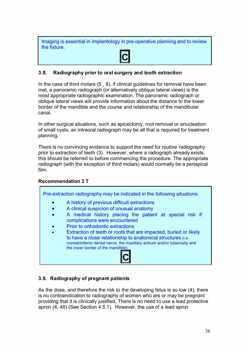
Imaging is essential in implantology in pre-operative planning and to reviewthe fixture.
C
7/14/2019 136_en
http://slidepdf.com/reader/full/136en 41/120
37
continues to be recommended (or advised) in some nation-states on thegrounds it may reassure the patient.
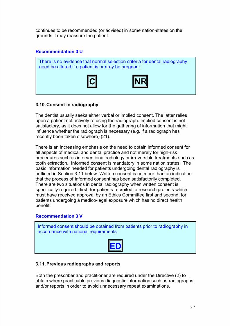
Recommendation 3 U
3.10.Consent in radiography
The dentist usually seeks either verbal or implied consent. The latter reliesupon a patient not actively refusing the radiograph. Implied consent is notsatisfactory, as it does not allow for the gathering of information that mightinfluence whether the radiograph is necessary (e.g. if a radiograph hasrecently been taken elsewhere) (21).
There is an increasing emphasis on the need to obtain informed consent for all aspects of medical and dental practice and not merely for high-riskprocedures such as interventional radiology or irreversible treatments such astooth extraction. Informed consent is mandatory in some nation states. Thebasic information needed for patients undergoing dental radiography isoutlined in Section 3.11 below. Written consent is no more than an indicationthat the process of informed consent has been satisfactorily completed.There are two situations in dental radiography when written consent isspecifically required: first, for patients recruited to research projects whichmust have received approval by an Ethics Committee first and second, for patients undergoing a medico-legal exposure which has no direct healthbenefit.
Recommendation 3 V
3.11.Previous radiographs and reports
Both the prescriber and practitioner are required under the Directive (2) toobtain where practicable previous diagnostic information such as radiographs
and/or reports in order to avoid unnecessary repeat examinations.
There is no evidence that normal selection criteria for dental radiographyneed be altered if a patient is or may be pregnant.
C NR
Informed consent should be obtained from patients prior to radiography inaccordance with national requirements.
ED
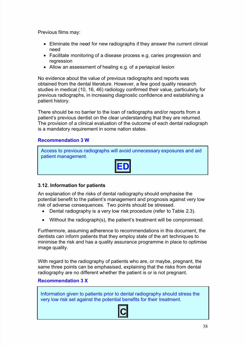
7/14/2019 136_en
http://slidepdf.com/reader/full/136en 42/120
38
Previous films may:
· Eliminate the need for new radiographs if they answer the current clinicalneed
· Facilitate monitoring of a disease process e.g. caries progression and
regression· Allow an assessment of healing e.g. of a periapical lesion
No evidence about the value of previous radiographs and reports wasobtained from the dental literature. However, a few good quality researchstudies in medical (10, 16, 46) radiology confirmed their value, particularly for previous radiographs, in increasing diagnostic confidence and establishing apatient history.
There should be no barrier to the loan of radiographs and/or reports from apatient’s previous dentist on the clear understanding that they are returned.The provision of a clinical evaluation of the outcome of each dental radiographis a mandatory requirement in some nation states.
Recommendation 3 W
3.12. Information for patients
An explanation of the risks of dental radiography should emphasise thepotential benefit to the patient’s management and prognosis against very lowrisk of adverse consequences. Two points should be stressed.
· Dental radiography is a very low risk procedure (refer to Table 2.3).
· Without the radiograph(s), the patient’s treatment will be compromised.
Furthermore, assuming adherence to recommendations in this document, thedentists can inform patients that they employ state of the art techniques to
minimise the risk and has a quality assurance programme in place to optimiseimage quality.
With regard to the radiography of patients who are, or maybe, pregnant, thesame three points can be emphasised, explaining that the risks from dentalradiography are no different whether the patient is or is not pregnant.
Recommendation 3 X
Access to previous radiographs will avoid unnecessary exposures and aidpatient management.
ED
Information given to patients prior to dental radiography should stress thevery low risk set against the potential benefits for their treatment.
C
7/14/2019 136_en
http://slidepdf.com/reader/full/136en 43/120
39
3.13. References
1. 1994. Consensus report of the European Society of Endodontology on quality guidelines for endodontictreatment. Int Endod J 27:115-124.
2. Council Directive 97/43/Euratom on health protection of individuals against the dangers of ionisingradiation in relation to medical exposure 1997. Official Journal of the European Communities No L 180/22.
3. 1999. Dental Protection. The whole tooth- and nothing but the tooth! Dental News 20:7-8.
4. 1994. Guidelines on Radiological standards for primary dental care. Volume 5 Number 3. Royal College of Radiologists and National Radiological Protection Board.5. 2000. National Institute for Clinical Excellence. Technology Appraisals Guidance- No. 1. Guidance on the
removal of wisdom teeth. National Institute for Clinical Excellence.6. Preventing Dental Caries in children at High Caries Risk. A National Clinical guideline. www.sign.ac.uk.
SIGN Publication Number 47. SIGN Executive, Royal College of Physicians, 9, Queen Street, EdinburghEH2 1JQ.
7. 1988. Review of methods of identification of high caries risk groups and individuals. Federation DentaireInternational Technical - Report no 31. Int Dent J, 38:177-89.
8. May 2002. Scottish Intercollegiate Guidelines Network (SIGN). A guideline developers' handbook. ReportNo.: SIGN 50.
9. 1998. Selection Criteria for Dental Radiography. Faculty of General Dental Practitioners, Royal College of Surgeons of England, London.
10. Aideyan, U. O., K. Berbaum, and W. L. Smith. 1995. Influence of prior radiologic information on theinterpretation of radiographic examinations. Acad Radiol 2:205-8.
11. Akerblom, A., M. Rohlin, and G. Hasselgren. 1988. Individualised restricted intraoral radiography versusfull-mouth radiography in the detection of periradicular lesions. Swed Dent J 12:151-159.
12. Angmar-Månsson, B. E., and S. Al-Khateeb. 1998. Caries Diagnosis. J Dent Educ 62:771-79.13. Atchinson, K. A. 1986. Radiographic examinations of orthodontic educators and practitioners. J Dent
Educ 50:651-55.14. Atchinson, K. A., L. S. Luke, and S. C. White. 1992. An algorithm for ordering pretreatment orthodontic
radiographs. Am J Orthodont Dentofac Orthoped 102:29-44.15. Atchinson, K. A., L. S. Luke, and S. C. White. 1991. Contribution of pretreatment radiographs to
orthodontists’ decision making. Oral Surg Oral Med Oral Pathol 71:238-45.16. Berbaum, K. S., and W. L. Smith. 1998. Use of reports of previous radiologic studies. Acad Radiol 5:111-
4.17. Bohay, R. N. 2000. The sensitivity, specificity, and reliability of radiographic periapical diagnosis of
posterior teeth. Oral Surg Oral Med Oral Pathol Oral Radiol Endod 89:639-642.18. Bohay, R. N., R. G. Stephens, and S. L. Kogon. 1998. A study of the impact of screening or selective
radiography on the treatment and postdelivery outcome for edentulous patients. Oral Surg Oral Med OralPathol Oral Radiol Endod 86:353-9.
19. Brooks, S. L., and S. Y. Cho. 1993. Validation of a specific selection criterion for dental periapicalradiography. Oral Surg Oral Med Oral Pathol 75:383-6.
20. Bruks, A., K. Enberg, I. Nordqvist, A. S. Hansson, L. Jansson, and B. Svenson. 1999. Radiographicexaminations as an aid to orthodontic diagnosis and treatment planning. Swed Dent J 23:77-85.
21. Dimond, B. C. 2002. Legal aspects of radiography and radiology. Blackwell Science Ltd, Oxford.22. Eliason, S., and G. Isacsson. 1992. Radiographic signs of temporomandibular disorders to predict
outcome of treatment. J Craniomandib Disord 6:281-87.23. Fava, L. R. D., and P. M. H. Dummer. 1997. Periapical radiographic techniques during endodontic
diagnosis and treatment. Int Endod J 30:250-261.24. Frederiksen, N. L. 1995. Diagnostic imaging in dental implantology. Oral Surg Oral Med Oral Pathol Oral
Radiol Endod 80:540-54.25. Giles, S. A., and N. G. Taylor. 1997. Are anterior occulsal radiographs still indicated for orthodontic
assessment? Br Dent J 183:325-328.26. Han, U. K., K. W. L. Vig, J. A. Weintraud, P. S. Vig, and C. J. Kowalski. 1991. Consistency of
orthodontic treatment decisions relative to diagnostic records. Am J Orthodont Dentofac Orthoped100:212-219.
27. Hintze, H., A. Wenzel, B. Danielson, and B. Nyvad. 1998. Reliability of visual examination, fibre-optictransillumination and bitewing radiography, and reproducibility of direct visual examination following tooth
separation for the identification of cavitated carious lesions in contacting approximal surfaces. 1998; 32:204-9. Caries Res, 32:204-9.
28. Hintze, H., A. Wenzel, and S. Williams. 1990. Diagnostic value of clinical examination for theidentification of children in need of orthodontic treatment compared with clinical examination and screeningpantomography. Eur J Orth 12:385-388.
29. Isaacson, K. G., and A. R. Thom (ed.). 2001. Guidelines for the use of radiographs in clinicalOrthodontics, 2nd ed. British Orthodontic Society, London.
30. Klein, R. M. F., S. A. Blake, B. R. Nattress, and P. N. Hirchmann. 1997. Evaluation of x-ray beamangulation for successful twin canal identification in mandibular incisors. Int Endod J 30:58-63.
31. Kogon, S. L., D. H. Charles, and R. G. Stephens. 1991. A clinical study of radiographic selection criteriafor edentulous patients. J Can Dent Assoc 57:794-8.
32. Kogon, S. L., R. G. Stephens, and R. N. Bohay. 1997. An analysis of the scientific basis for theradiographic guideline for new edentulous patients. Oral Surg Oral Med Oral Pathol Oral Radiol Endod83:619-23.
33. Lekholm, U., and G. A. Zarb. 1985. Patient selection and preparation. In P. I. Brånemark, G. A. Zarb, andT. Albrektsson (ed.), Tissue integrated prosthesis. Osteointegration in Clinical Dentistry.Quintessence,
Berlin.34. Luke, L. S., P. Lee, K. A. Atchison, and S. C. White. 1997. Orthodontic residents' indications for use of
the lateral TMJ tomogram and the posteroanterior cephalogram. J Dent Educ 61:29-36.
7/14/2019 136_en
http://slidepdf.com/reader/full/136en 44/120
40
35. Orstavik, D. 1996. Time-course and risk analyses of the development and healing of chronic apicalperiodontitis in man. Int Endod J 29:150-155.
36. Pepelassi, E. A., and A. Diamanti-Kipioti. 1997. Selection of the most accurate method of conventionalradiography for the assessment of periodontal osseous destruction. J Clin Periodontol 24:557-567.
37. Richardson, P. S. 1997. Selective periapical radiology compared to panoramic screening. Prim Dent Care4:95-9.
38. Richmond, S., K. O'Brien, A. Buchanan, and D. Burden. 1992. An introduction to occlusal indices.ORTHO-CARE (UK) Ltd., Bradford, UK.
39. Rushton, V. E., K. Horner, and H. M. Worthington. 2002. Screening panoramic radiography of new adultpatients in general dental practice: diagnostic yield when combined with bitewing radiography andidentification of selection criteria. Br Dent J 192:275-279.
40. Rushton, V. E., K. Horner, and H. V. Worthington. 1999. Aspects of panoramic radiography in generaldental practice. Br Dent J 186:342-4.
41. Rushton, V. E., K. Horner, and H. V. Worthington. 2001. Screening panoramic radiology of adults ingeneral dental practice: radiological findings. Br Dent J 190:495-501.
42. Shaw, W. C., K. O'Brien, and S. Richmond. 1991. Indices of orthodontic treatment need and treatmentstandards. Br Dent J 170:107-112.
43. Shelley, A. 2000. The Bridge. BUPA Dental Cover 19:4.44. Stookey, G. K., and C. González-Cabezas. 2001. Emerging methods of caries diagnosis. J Dent Educ
65:1001-06.45. Tugnait, A., V. Clerehugh, and P. N. Hirschmann. 2000. The usefulness of radiographs in diagnosis and
management of periodontal diseases: a review. J Dent 28:219-226.46. White, K., K. Berbaum, and W. L. Smith. 1994. The role of previous radiographs and reports in the
interpretation of current radiographs. Invest Radiol 29:263-5.
47. White, S. C., E. W. Heslop, L. G. Hollender, K. M. Mosier, A. Ruprecht, M. K. Shrout, and AmericanAcademy of Oral Maxillofacial Radiology ad hoc Committee on Parameters of Care. 2001.Parameters of radiologic care: An official report of the American Academy of Oral and MaxillofacialRadiology. Oral Surg Oral Med Oral Pathol Oral Radiol Endod 91:498-511.
48. Wood, R. E., A. M. P. Harris, E. J. van der Merwe, and C. J. Nortje. 1991. The leaded apronrevisited:Does it reduce gonadal radiation dose in dental radiology? Oral Surg Oral Med Oral Pathol71:642-46.
7/14/2019 136_en
http://slidepdf.com/reader/full/136en 45/120
41
4 Equipment factors in reduction of radiation dosesto patients
In Section 2, review of the literature demonstrated that individual doses andrisks to patients in dental radiography were low. However, these figures arebased upon laboratory studies using phantoms rather than ‘real life’. Dosesurveys have revealed wide variations in doses given to patients for the sameexamination. Such variations reflect the variability in performance of different
X-ray equipment and materials. In this section the importance of selection of appropriate equipment and materials in limiting doses (and hence risk) isreviewed.
4.1 X-ray generation and kilovoltageThe kilovoltage of an X-ray machine is the potential difference that existsacross the X-ray tube during use. Kilovoltage controls the mean and peak X-ray energies in the X-ray beam. Low kilovoltages, giving lower energy X-rays,leads to higher skin doses for patients(22). They also necessitate longer exposure times than would be needed for a higher kilovoltage X-ray set(milliamperage assumed to be equal). These factors have led to lower limits to
be set for kilovoltage in legislation from various countries, usually in the 50 to60 kV region. Higher kilovoltages reduce skin dose, but lead to higher ‘depth’dose(18) and more scatter of X-rays. In the case of dental (intraoral) X-raysets, kilovoltage is usually either fixed or minimally variable.
An important consideration with dental (intraoral) radiography is the X-rayspectral sensitivity of dental X-ray film and the image quality at differentkilovoltages. Increasing the kilovoltage much beyond 70 kV would result in aspectrum ill-matched to the optimal sensitivity of dental film (22). ‘Low’kilovoltages produce images of higher contrast than do higher kilovoltages.This reflects the different types of attenuation of low and high energy
radiation. There is debate about the optimal kilovoltage for dental work, withsome authorities recommending higher values, particularly in the USA.
A kilovoltage of around 60-70 kV for intraoral radiography is considered to bea reasonable compromise choice in terms of limiting dose and all-rounddiagnostic efficacy (22).
Recommendation 4 A
The aim of this section is to:
· Describe the ways in which radiation dose is influenced byselection of equipment and materials
· Derive recommendations on equipment and materials
65 to 70 kV is recommended as the kilovoltage of choice for dental(intraoral) X-ray sets using AC equipment, with 60kV for those using DC X-
ray sets.
B
7/14/2019 136_en
http://slidepdf.com/reader/full/136en 46/120
42
Unlike intraoral radiography, kilovoltage is used as the principle means of exposure control for panoramic radiography. Thus most panoramic X-raymachines offer a wide range of kilovoltages to the operator. Choice of kilovoltage is principally governed by the need to control X-ray intensity andby the energy sensitivity of the film/screen combination.
Constant potential (‘direct current’) X-ray generation is a modern alternative totraditional pulsating kilovoltage for both dental (intraoral) and panoramic/cephalometric equipment. Such a method of X-ray generation producesproportionately fewer low energy X-rays(22, 34, 41) and hence givesreductions in skin dose for patients. The mean X-ray energy from a constantpotential (DC) X-ray set is higher than that from an alternating potential (AC)X-ray set at the same operating kilovoltage. It has been demonstrated that for a constant potential set a kilovoltage setting of 5-8 kV lower is needed tomaintain radiographic contrast (19). Thus 60 kV is recommended as theoptimal operating potential for intraoral work. Constant potential equipment
provides more predictable and accurate X-ray output and is therefore a better choice for use with digital receptor systems.
Recommendation 4B
4.2 FiltrationFiltration of the X-ray beam preferentially removes lower energy X-rayphotons from the beam. Thus it is invaluable as a means of reducing skindoses to patients. Filtration using aluminium is an established component of dental X-ray equipment. Such filtration is fitted at manufacture and is thereforea factor that is not readily under the control of the dentist.
Recommendation 4 C
Additional filtration using materials (K-edge filters) other than aluminium, suchas rare-earth materials, have been investigated as means of dose reduction inintraoral dental radiography by a number of researchers (22, 25, 30, 31, 33,46, 52, 54). The underlying reason for their use is that they ‘shape’ the X-rayspectrum and more closely match the spectral sensitivity of dental film. The
evidence appears to be that all offer reductions in dose (22, 25, 30, 31, 33,46, 54), but that this must be balanced against cost (54), effects on image
Constant potential (‘DC’) X-ray equipment is recommended whenpurchasing new X-ray equipment, especially when digital image receptorssystems are chosen.
C
Filtration by aluminium is a key method of reducing skin dose to patients.
B
7/14/2019 136_en
http://slidepdf.com/reader/full/136en 47/120
43
quality(46) and the likely increase in exposure times associated with their use.Dose reduction has also been demonstrated for panoramic radiography (24).Rare-earth filtration offers some dose reduction in intraoral radiography, but itshould only be adopted after advice from a medical physics expert on settingnew exposure factors.
4.3 Collimation, field-size trimmingReducing the size of the X-ray beam to the minimum size needed to imagethe object of interest is an obvious means of limiting dose to patients. Limitingbeam area on the skin surface also limits the volume of the patient that isirradiated. As well as ‘field size’ on the patient’s skin being important, the X-ray source to skin distance plays a role in limiting doses. Because of thedivergence of the X-ray beam, increasing this distance reduces thedivergence within the patient and therefore reduces the volume irradiated.
4.3.1 Intraoral radiography
On dental X-ray sets for intraoral radiography field size is constrained bycollimation of the beam. Visualisation of the field size is facilitated by the‘position indicating device’ (PID).
Short pointed PIDs were once favored because the conical shape allowed aless obstructed view of film/teeth relationship and provided a visual indicationof the central ray (9). However, in the last 20 years most dental intraoral setshave been manufactured with an open-ended PID of 60 mm diameter. Acircular beam of this size is 135% larger in area than a conventional dentalfilm (30 x 40 mm), indicating an obvious way of reducing patient dose(22).
Various investigators have estimated that rectangular collimation can achievedose reductions exceeding 60% in dental radiography(9, 13, 18). Cederbergand associates (9) calculated and compared the effective dose and alsoestimated the risk from the use of short and long, round and rectangular open-end PIDs and a short pointed closed-end PID. They reported that both longand short rectangular collimation resulted in the lowest effective doses, withvalues 3.5 to 5 times less than round collimation. They also demonstrated thatthe use of pointed closed-end PIDs equates to a risk of 5.6 times that of along rectangular PID.
The adoption of rectangular collimation (30 x 40 mm beam) has been
recommended in both UK (21, 36) and USA (2, 55). However, it is importantto remember that use of rectangular collimation requires the use of filmholding devices with a beam alignment guide to prevent cone cuts.Rectangular collimation can be achieved by replacing the round PID with arectangular one, attaching a special rectangular collimating plate to the end of the round PID or using a film holder that incorporates a metal shield to blockradiation beyond the edges of the film (2). These possibilities mean thatexisting equipment can easily be adapted to allow rectangular collimation(36).
7/14/2019 136_en
http://slidepdf.com/reader/full/136en 48/120
44
Recommendation 4 D
Where circular X-ray beams continue to be used, the beam diameter must notexceed 60 mm. Beam collimators/directors should be open ended and providea minimum focus-to-skin distance (FSD) of 200 mm.
4.3.2 Panoramic radiography
Panoramic radiography was designed originally as a means of examining the jaws and the teeth. However, the radiographed area is frequently far inexcess of that of diagnostic interest. Dentists had no facility for reducing thearea irradiated. However, several machines now offer programmed field-sizetrimming as a means of reducing patient dose. Field limitation cansignificantly reduce patient exposure when specific diagnostic information isrequired. New equipment should be provided with automatic selection of beam limitation, although manual selection is acceptable (36). The beam
height at the receiving slit or secondary collimator should be restricted to nogreater than that required to expose the area of diagnostic interest andcertainly no greater than the film (should normally be 120 or 150 mm). Thebeam width should normally be no greater than 5 mm(36).
Some new panoramic machines have a ‘child-imaging mode’, which reducesthe exposed area by 27 to 45% (22). Some also offer more sophisticatedprogrammes to permit imaging of individual jaw segments andtemporomandibular joints. In a study, Lecomber and Faulkner(27) reportedthat by using a field size programme on the Orthophos X-ray unit limited tothe tooth bearing regions of the jaws, effective dose could be reduced by
more than 50%. Such facilities offer a simple way of reducing dose and thepurchase of machines with these facilities should be encouraged.
Recommendation 4 E
Rectangular collimation is a highly effective means of dose reductionin intraoral dental radiography. It should be used in combination with
film holders incorporating beam-aiming devices. In those cases wherefilm holders are not possible, rectangular collimation should still beconsidered.
B
If available, limitation of field size to the area required for diagnosis shouldbe used for panoramic radiography.
B
7/14/2019 136_en
http://slidepdf.com/reader/full/136en 49/120
45
4.3.3 Cephalometric radiography
Cephalometry (also known as teleradiography) traditionally produces imagesof the entire head and much of the cervical spine. However, the area of interest to orthodontists usually stops at the level of the base of the skull. ABritish Orthodontic Society working party supported the concept of reductionof lateral cephalogram dosage by the use of modified wedge collimation toremove part of the skull from diagnostic area (22, 32). This viewpoint issupported in other publications(49, 55). Although such collimation shouldsignificant reduce patient dose, manufactures of cephalometric equipmenthave not yet included this form of collimation as standard. Further collimationof the lateral cephalogram to show the maxilla and mandible only is a viablealternative for measuring cephalometric values during treatment(32).
Recommendation 4 F
Soft tissue profile using wedge filters is usual on lateral cephalometricradiographs. Some dose reduction can be included by placing the filter
between the patient and the X-ray source rather than between the patient andthe cassette (22, 55).
4.4 Choice of image receptor
4.4.1 Intraoral radiography
Until 1980, the fastest intraoral film commercially available was film of groupD. In 1981, E-speed films became available, capable of reducing the amountof radiation by approximately 50%. However, this fast film had a lower inherent contrast, was very sensitive to aged and depleted solutions and lost
its high speed at higher densities
(48). This was probably the main reasonthat only a few dentists adopted this type of film(6, 8, 20, 38, 42, 45).
Subsequent developments in film technology by various manufacturers havedelivered improved E-speed emulsions (44, 56) and films that fall into the ISOspeed group F. One brand of F-speed film that is widely available has beenshown to offer dose reductions of 20-25% compared with the samemanufacturer’s E-speed film(14, 29, 43).
In conclusion, for intraoral radiography the fastest available films consistentwith satisfactory diagnostic results should be used. Intraoral films of ISO
speed groups E or F are recommended because they reduce the radiationdose more than 50% compared with group D-speed films. The use of instant
Where possible, lateral cephalograms should be collimated to limit thefield to the area required for diagnosis. Manufacturers must incorporatethis feature into the design of cephalographic equipment.
B
7/14/2019 136_en
http://slidepdf.com/reader/full/136en 50/120
46
process film, which have slower speeds and limitations in image quality (10),should be limited to specific essential situations, as in endodontics or pre-extraction cases during out-of-hours care.
Recommendation 4 G
4.4.2 Extraoral radiography
For panoramic, cephalometric and other extraoral radiographs, the fastestavailable film-intensifying screen combination consistent with satisfactorydiagnostic results should be used. The film screen combination should be atleast 400 and the light sensitivity of the film should be correctly matched withthe intensifying screens. The introduction of rare-earth intensifying screen/filmcombination has been shown to give dose reduction of around 50% for panoramic and cephalometric radiology (22).
Manufacturers generally emphasize the use of matched combinations of orthochromatic film and rare-earth screens because such combinations moreefficiently convert radiation energy to light in comparison with orthochromatic
film combined with calcium tungstate screens (53). Since rare-earth phosphor screens were introduced in 1972, manufacturers have tried to develop suchcombinations in order to improve speed and to increase sharpness of theradiographic images
A number of studies have been carried out to evaluate the sensitometricproperties of these film-screen combinations (47, 51, 53). Wide latitude filmsperform better for panoramic radiography than higher contrast films.
Recommendation 4 H
4.4.3 Digital receptors
Recently, several digital imaging systems have been introduced as
alternatives to conventional radiographic techniques. The digital images aresupposed to achieve images of high diagnostic quality, at least equal to that of
For intraoral radiography, only the fastest available (Group E or faster)films should be used, as they significantly reduce patient dose.
A NR
For extraoral radiography the fastest available rare-earth intensifyingscreen/film combination consistent with satisfactory diagnostic resultsshould be used. The speed of the system should be at least 400.
A
7/14/2019 136_en
http://slidepdf.com/reader/full/136en 51/120
47
conventional radiographic film. Furthermore, the images are displayedimmediately on the computer monitor and no processing chemicals or equipment are necessary.
Two types of intraoral digital systems are currently available. The first type
involves those systems that they are using imaging sensors based on charge-coupled devices (CCD). The first system for direct digital intraoral radiographywas introduced in 1989 and was based on a CCD sensor sensitive to visiblelight. CCD systems convert radiation into visible light by using a scintillationscreen. The light is transferred to the CCD via fibre optic coupling or opticallenses. The pattern of light is detected and converted to an electronic signalthat is passed to the computer for conversion into an image. The number of CCD systems available for intraoral radiography has increased rapidly. Today,most sensors use a scintillation layer to improve the quantum efficiency of thesystem. Improvements in pixel size, in the active area of the sensor, in spatialresolution, noise and image manipulation have been made by manufacturers
in recent years. Recently some sensors have been developed with smaller pixel size and with the use of the so-called Active Pixel Sensor (APS) andComplementary Metal-Oxide Semiconductor (CMOS) technologies. Severalstudies have evaluated the physical and clinical performance of the majority of the intraoral digital systems(3, 4, 12, 17, 26, 35, 37).
The second type of digital intraoral system uses photostimulable storagephosphor (PSP) image plates. The plates consist of a polyester base coatedwith a crystalline halide composed of europium-activated barium fluorohalidecompounds. When the image plate is irradiated, the absorbed X-ray energy isstored as a latent image within the phosphor crystals. In a scanner, a narrowlaser beam causes the release of the stored energy as visible blue light that isturned into an analog electronic signal and thereafter digitized. Scanning isaccomplished in about 25 seconds and the resulting image is displayed on thecomputer monitor. In contrast to CCD systems, storage phosphor systems arecordless.
Each of these two types of intraoral digital systems has advantages anddisadvantages. Because image acquisition is more rapid with CCD systemsthan with PSP, the former may be more useful when ‘instant’ radiographs aredesirable. In contrast, PSP systems are wireless and use a larger size image
plate, approximately the size of a No.2 periapical film. One of the mostimportant advantages of digital radiography is the reduction of radiation dose.Various studies have shown that the amount of radiation needed to create animage for both types of intraoral system is lower than with film.
One study demonstrated that the optimal exposure time for all systems wasapproximately half that needed for conventional film and that digital imageshad to be modified by adjusting the contrast and brightness to optimize thevisibility of the region of interest(37). Another study(39) reported that a CCDsystem provided reduction in average skin entrance dose of 31-34% whencompared with E-speed film; with added niobium filtration the reduction was
found to be 51-60%. PSP systems have a wide exposure latitude and Borg
7/14/2019 136_en
http://slidepdf.com/reader/full/136en 52/120
48
and Grondahl (7) found that reliable endodontic measurements could beobtained even at very low exposure settings.
Although digital radiography offers a significant dose reduction, the number of retakes (essentially due to bad positioning of the bulky CCD with its’
encumbering wire) may result in increased dose for the patient. Furthermore,due to smaller sensor sizes, more than one exposure may be required tocover the anatomical area imaged using a single conventional film. Problemswith positioning sensors have been reported as leading to high reject rate(23).
Recommendation 4 I
For panoramic and cephalometric radiography, the same two types of digitalsystems are also available. For CCD systems, conventional film is replacedby a long vertical CCD. The same sensor is used in cephalometricradiography, where the CCD is mounted on the cephalostat behind thepatient’s head. The patient’s head is scanned in lines with a flat, fan shapedX-ray beam. During the scanning process, which takes about 15 seconds, the
patient must stay motionless. The second type of digital panoramic andcephalometric system uses a PSP plate in place of the conventional filmcassette.
Panoramic and cephalometric digital radiography have the same clinicaladvantages as intraoral digital radiography, although dose reduction is notexpected to be as effective as with intraoral systems. The exposure settingsof CCD type panoramic units require exposures that are almost equal to thoseof machines using film/screen combinations. There will be no dose reduction.Some papers however, report that, depending on the diagnostic task, a lower exposure of the radiograph could be sufficient when density and contrast can
be adjusted from the software features(11, 15, 16, 28, 50). This is one of thebenefits of digital radiography where the density and contrast of an image canbe optimized after the image has been taken. This is different to conventionalradiography, where the contrast and density cannot be changed after theimage is taken.
Recommendation 4 J
4.5 Lead protection of patients
Intraoral digital radiography offers a potential dose reduction. A medicalphysics expert should be consulted to achieve dose reduction optimisation.
B
It is unlikely that digital panoramic and cephalometric radiography canroutinely offer dose reduction compared with conventional screen/filmcombinations. A medical physics expert should be consulted to achieve
dose reduction optimisation.
C
7/14/2019 136_en
http://slidepdf.com/reader/full/136en 53/120
49
4.5.1 Leaded aprons
Lead aprons do not protect against scattered radiation internally within thebody and in the case of panoramic radiography, they may physically interferewith the procedure and degrade the final image (21). Despite the extremelylow gonadal dose associated with dental radiography, the use of a lead apronhas been recommended in the past in order to allay patient anxiety. However,it has been shown that gonadal doses are not significantly different in dentalradiography with and without a lead apron (22). UK Guidance Notes for dentalpractitioners on the safe use of X-ray equipment (36), clearly state that thereis no justification for the routine use of lead aprons for patients in dentalradiography. An official report of the American Academy of Oral andMaxillofacial Radiology (55), pointed out that the value of leaded aprons isminimal compared with the benefits of the use of E-speed films andrectangular collimation. It was concluded that their use could be consideredoptional except when required by law. See Section 3.8 for comments on
radiography in pregnant patients.
Recommendation 4 K
4.5.2 Thyroid collar
The thyroid gland is one of the more radiosensitive organs in the head andneck region. It is frequently exposed to scattered radiation and occasionally toprimary beam during dental radiography. Because people under age 30 are atgreater risk of radiation induced thyroid cancer than older individuals, somehave argued that thyroid collars should be used when intraoral radiographicexaminations are made on this population(55). However, it is probable thatrectangular collimation for intraoral radiography offers similar level of thyroidprotection to lead shielding, in addition to its other dose reducing effects (21,
22, 40). Thyroid shielding is inappropriate for panoramic radiography as it mayinterfere with the primary beam. In cephalometric radiography lead thyroidprotection is necessary if the beam collimation does not exclude the thyroidgland. Thyroid shielding was found to reduce radiation doses of 45% duringCT of the head and is strongly recommended, especially in younger agegroups (5).
There is no evidence to justify routine use of abdominal (gonadal) leadprotection for dental radiography.
C NR
7/14/2019 136_en
http://slidepdf.com/reader/full/136en 54/120
50
Recommendation 4 L
Patient doses should be kept as low as reasonably achievable. In dentalradiography, patient dose limitation involves consideration of the X-rayequipment, the beam size, the image receptor and, occasionally, the use of lead protection. Optimizations of each of these acts synergistically tosubstantially reduce doses.
For intraoral radiography the effect of altering the various equipment factors isdemonstrated in Table 4.1. It is possible to see that a shift from the baseline
equipment to a constant potential set, rectangular collimation and F-speedfilm would lead to a dose reduction of about two thirds of the original level.
Table 4.1: The effect upon dose of equipment modification whencompared with a baseline of a 70 kV AC dental X-ray set with a 60 mmcylindrical beam used with E-speed film.
Equipment factors Multiplication factor upon dose
Digital systems(Phosphor plate or CCD)
x 0.5 – 0.75
Rectangular collimation (30 x 40 mm) x 0.5F-speed film x 0.8
‘DC’ constant potential set x 0.8
‘Short cone’(100 mm source to skin distance)
x 1.5
50 kV set x 2.0
D-speed film x 2.0
The multiplication factors indicate the effects upon dose. Table adapted from (1)
Similar modifications can be made for other types of dental radiography(panoramic, cephalometric).
Some dose limitations can only be achieved by purchase of new equipment.However, some entail minimal (e.g. rectangular collimation) or no (e.g. F-speed film) additional costs to the dentist. Such low cost options should beadopted as a priority.
4.7 References
1. 1998. Selection Criteria for Dental Radiography. Faculty of General Dental Practitioners, Royal College of Surgeons of England, London.
2. ADA. 2001. Council on Scientific affairs - An update on radiographic practices: information andrecommendations. J Am Dent Assoc 132:234-238.
Lead shielding of the thyroid gland should be used in those cases wherethe thyroid is in line of, or very close to, the primary beam.
C
7/14/2019 136_en
http://slidepdf.com/reader/full/136en 55/120
51
3. Attaelmanan, A. G., E. Borg, and H. G. Grondahl. 1999. Assessments of the physical performance of 2generations of 2 direct digital intraoral sensors. Oral Surg Oral Med Oral Pathol Oral Radiol Endod 88:517-23.
4. Attaelmanan, A. G., E. Borg, and H. G. Grondahl. 2001. Signal-to-noise ratios of 6 intraoral digitalsensors. Oral Surg Oral Med Oral Pathol Oral Radiol Endod 91:611-5.
5. Beaconsfield, T., R. Nicholson, A. Thornton, and A. Al-Kutoubi. 1998. Would thyroid and breastshielding be beneficial in CT of the head? Eur Radiol 8:664-7.
6. Bohay, R. N., S. L. Kogon, and R. G. Stephens. 1994. A survey of radiographic techniques and
equipment used by a sample of general dental practitioners. Oral Surg Oral Med Oral Pathol 78:806-10.7. Borg, E., and H. G. Grondahl. 1996. Endodontic measurements in digital radiographs acquired by a
photostimulable, storage phosphor system. Endod Dent Traumatol 12:20-4.8. Button, T. M., W. C. Moore, and A. D. Goren. 1999. Causes of excessive bitewing exposure: results of a
survey regarding radiographic equipment in New York. Oral Surg Oral Med Oral Pathol Oral Radiol Endod87:513-7.
9. Cederberg, R. A., N. L. Frederiksen, B. W. Benson, and T. W. Sokolowski. 1997. Effect of the geometryof the intraoral position-indicating device on effective dose. Oral Surg Oral Med Oral Pathol Oral RadiolEndod 84:101-9.
10. Czajka, J., V. E. Rushton, A. C. Shearer, and K. Horner. 1996. Sensitometric and image qualityperformance of "rapid" intraoral film processing techniques. Br J Radiol 69:49-58.
11. Dula, K., G. Sanderink, P. F. van der Stelt, R. Mini, and D. Buser. 1998. Effects of dose reduction on thedetectability of standardized radiolucent lesions in digital panoramic radiography. Oral Surg Oral Med OralPathol Oral Radiol Endod 86:227-33.
12. Farman, A. G., W. C. Scarfe, D. B. Schick, and P. M. Rumack. 1995. Computed dental radiography:evaluation of a new charge coupled device- based intraoral radiographic system. Quintessence Int 26:399-
404.13. Freeman, J. P., and J. W. Brand. 1994. Radiation doses of commonly used dental radiographic surveys.
Oral Surg Oral Med Oral Pathol 77:285-9.14. Geist, J. R., and J. W. Brand. 2001. Sensitometric comparison of speed group E and F dental
radiographic films. Dentomaxillofac Radiol 30:147-52.15. Gijbels, F., C. Bou Serhal, G. Willems, H. Bosmans, G. Sanderink, M. Persoons, and R. Jacobs.
2001. Diagnostic yield of conventional and digital cephalometric images: a human cadaver study.Dentomaxillofac Radiol 30:101-5.
16. Hagemann, K., D. Vollmer, T. Niegel, U. Ehmer, and I. Reuter. 2000. Prospective study on thereproducibility of cephalometric landmarks on conventional and digital lateral headfilms. J OrofacialOrthopedics 61:91-9.
17. Harada, T., K. Nishikawa, H. Shibuya, Y. Hayakawa, and K. Kuroyanagi. 1995. Sens-A-Raycharacteristics with variations in beam quality. Oral Surg Oral Med Oral Pathol Oral Radiol Endond 80:120-123.
18. Hayakawa, Y., H. Fujimori, and K. Kuroyanagi. 1993. Absorbed doses with intraoral radiography.Function of various technical parameters. Oral Surg Oral Med Oral Pathol 76:519-24.
19. Helmrot, E., G. A. Carlsson, and O. Eckerdal. 1994. Effects of contrast equalization on energy impartedto the patient: a comparison of two dental generators and two types of intraoral film. DentomaxillofacRadiol 23:83-90.
20. Hintze, H. 1993. Radiographic screening examination: frequency, equipment, and film in general dentalpractice in Denmark. Scand J Dent Res 101:52-6.
21. Hirschmann, P. N. 1995. Guidelines on radiology standards for primary dental care: a resume. RoyalCollege of Radiologists and the National Radiological Protection Board. Br Dent J 178:165-7.
22. Horner, K. 1994. Review article: radiation protection in dental radiology. Br J Radiol 67:1041-9.23. Horner, K., A. C. Shearer, A. Walker, and N. H. F. Wilson. 1990. Radiovisiography: an initial evaluation.
Br Dent J 168:244-248.24. Kapa, S. F., and D. A. Tyndall. 1989. A clinical comparison of image quality and patient exposure
reduction in panoramic radiology with heavy metal filtration. Oral Surg Oral Med Oral Pathol 67:750-759.25. Kapa, S. F., D. A. Tyndall, and T. E. Ouellette. 1990. The application of added beam filtration to intraoral
radiography. Dentomaxillofac Radiol 19:67-74.26. Kunzell, A., and C. Benz. 1997. Noise in digital dental radiographs. Dentomaxillofac Radiol 26:261-285.27. Lecomber, A. R., and K. Faulkner. 1993. Dose reduction in panoramic radiography. Dentomaxillofac
Radiol 22:69-73.28. Lim, K. F., and K. W. Foong. 1997. Phosphor-stimulated computed cephalometry: reliability of landmarkidentification. Br J Orthodont 24:301-8.
29. Ludlow, J. B., E. Platin, and A. Mol. 2001. Characteristics of Kodak Insight, an F-speed intraoral film.Oral Surg Oral Med Oral Pathol Oral Radiol Endod 91:120-9.
30. MacDonald-Jankowski, D. S., and C. P. Lawinski. 1992. The effect of thin K-edge filters on radiationdose in dental radiology. Br J Radiol 65:990-995.
31. MacDonald-Jankowski, D. S., and C. P. Lawinski. 1991. The reduction in radiation dose for intraoralradiographs by the use of thin K-edge filters. Br J Radiol 64:524-528.
32. Mandall, N. A., K. D. O'Brien, and H. V. Worthington. 1999. Radiation reduction using a modifiedcollimated lateral skull radiograph during orthodontic treatment. Clin Orthodont Res 2:179-85.
33. Mauriello, S. M., V. P. Overman, and G. B. Mann. 1996. Clinical evaluation of a samarium compoundfilter and E-speed film. Quintessence Int 27:769-73.
34. McDavid, W. D., U. Welander, B. K. Pillai, and C. R. Morris. 1982. The Intrex: a constant potential x-rayunit for periapical dental radiography. Oral Surg Oral Med Oral Pathol 53:433-436.
35. Molteni, R. 1992. Visualix, a new system for direct dental X-ray imaging: a preliminary report.
Dentomaxillofac Radiol 21:222-223.36. National Radiological Protection Board. 2001. Guidance notes for dental practitioners on the safe use of x-ray equipment. Department of Health, London.
7/14/2019 136_en
http://slidepdf.com/reader/full/136en 56/120
52
37. Pfeiffer, P., P. Schmage, I. Nergiz, and U. Platzer. 2000. Effects of different exposure values ondiagnostic accuracy of digital images. Quintessence Int 31:257-60.
38. Platin, E., A. Janhom, and D. Tyndall. 1998. A quantitative analysis of dental radiography qualityassurance practices among North Carolina dentists. Oral Surg Oral Med Oral Pathol Oral Radiol Endod86:115-20.
39. Scarfe, W. C., A. G. Farman, J. W. Brand, and M. S. Kelly. 1997. Tissue radiation dosages using theRVG-S with and without niobium filtration. Aust Dent J 42:335-42.
40. Schmidt, K., X. L. Velders, F. C. van Ginkel, and P. F. van der Stelt. 1998. Het gebruik van een
loodkraag bij intraorale rontgenopnamen. Ned Tijdschr Tandheelkd 105:209-212.41. Stenstrom, B., P. Julin, and L. Karlsson. 1987. Comparison between panoramic radiographic
techniques. Part IV: Absorbed doses and energy imparted from the Orthopantomograph model OP10.Dentomaxillofac Radiol 16:11-15.
42. Svenson, B., and A. Petersson. 1995. Questionnaire survey on the use of dental X-ray film andequipment among general practitioners in the Swedish Public Dental Health Service. Acta Odontol Scand53:230-5.
43. Syriopoulos, K., X. L. Velders, G. C. Sanderink, and P. F. van Der Stelt. 2001. Sensitometric andclinical evaluation of a new F-speed dental X-ray film. Dentomaxillofac Radiol 30:40-4.
44. Syriopoulos, K., X. L. Velders, G. C. Sanderink, F. C. van Ginkel, and P. F. van der Stelt. 1999.Sensitometric evaluation of four dental X-ray films using five processing solutions. Dentomaxillofac Radiol28:73-9.
45. Syriopoulos, K., X. L. Velders, P. F. van der Stelt, F. C. van Ginkel, and K. Tsiklakis. 1998. Mail surveyof dental radiographic techniques and radiation doses in Greece. Dentomaxillofac Radiol 27:321-8.
46. Tetradis, S., G. Scaf, A. G. Lurie, and M. L. Freedman. 1995. Niobium filtration of conventional and high-frequency x-ray generator beams for intraoral radiography. Effects on absorbed doses, image density and
contrast, and photon spectra. Oral Surg Oral Med Oral Pathol Oral Radiol Endod 80:232-41.47. Thunthy, K. H., and R. Weinberg. 1997. Film-screen systems: sensitometric comparison of Kodak
Ektavision system to Kodak T-Mat/RA system. Oral Surg Oral Med Oral Pathol Oral Radiol Endod 83:288-92.
48. Thunthy, K. H., and R. Weinberg. 1995. Sensitometric comparison of Kodak EKTASPEED Plus,Ektaspeed, and Ultra-speed Dental Films. Oral Surg Oral Med Oral Pathol Oral Radiol Endod 79:114-6.
49. Tsiklakis, K., C. Donta-Bakoyanni, M. Tassopoulou, and V. Kamenopoulou. 2000. Absorbed radiationdose during lateral cephalometric radiography: comparison of screen-film systems and field-sizecombinations. J Clin Pediat Dent 24:117-21.
50. Visser, H., T. Rodig, and K. P. Hermann. 2001. Dose reduction by direct-digital cephalometricradiography. Angle Orthodontist 71:159-63.
51. Wakoh, M., A. G. Farman, H. Kitagawa, K. Nishikawa, and K. Kuroyanagi. 1998. A sensitometriccomparison of Kodak Ektavision and Fuji Super HR-S panoramic radiographic films. Oral Surg Oral MedOral Pathol Oral Radiol Endod 86:249-53.
52. Wakoh, M., A. G. Farman, W. C. Scarfe, M. S. Kelly, and K. Kuroyanagi. 1995. Perceptibility of defectsin an aluminum test object: a comparison of the RVG-S and first generation VIXA systems with and without
added niobium f iltration. Dentomaxillofac Radiol 24:211-4.53. Wakoh, M., K. Nishikawa, N. Kobayashi, A. G. Farman, and K. Kuroyanagi. 2001. Sensitometric
properties of Agfa Dentus OrthoLux, Agfa Dentus ST8G, and Kodak Ektavision panoramic radiographicfilm. Oral Surg Oral Med Oral Pathol Oral Radiol Endod 91:244-51.
54. White, S. C., and B. M. Gratt. 1991. Evaluation of Niobi-X filtration in intraoral radiology. Oral Surg OralMed Oral Pathol 72:746-755.
55. White, S. C., E. W. Heslop, L. G. Hollender, K. M. Mosier, A. Ruprecht, M. K. Shrout, and AmericanAcademy of Oral Maxillofacial Radiology ad hoc Committee on Parameters of Care. 2001.Parameters of radiologic care. An official report of the American Academy of Oral and MaxillofacialRadiology. Oral Surg Oral Med Oral Pathol Oral Radiol Endod 91:498-511.
56. White, S. C., and D. C. Yoon. 2000. Comparison of sensitometric and diagnostic performance of two films.Compendium of Continuing Education in Dentistry (Jamesburg, NJ) 21:530-2, 534, 536 passim.
7/14/2019 136_en
http://slidepdf.com/reader/full/136en 57/120
53
5 Quality standards and quality assurance
The purpose of Quality Assurance (QA) in dental radiology is to ensureconsistently adequate diagnostic information, while radiation doses arecontrolled to be as low as reasonably achievable.
5.1 Quality assurance programme
A well-designed QA programme should be comprehensive but inexpensive tooperate and maintain for the dentist and staff.
QA should address the following:
· Image quality assessment· Practical radiographic technique
· Patient dose and X-ray equipment
· Darkroom, film, cassettes and processing
The QA programme should entail surveys and checks that are performedaccording to a regular timetable. A written log of this programme should bemaintained by staff to ensure adherence to the programme and to raise itsimportance among staff. A specific person should be named as leader for theQA programme.
Recommendation 5 A
5.2 Image quality assessment
Ensuring radiographs of consistently acceptable quality is obviously of benefitto patient and dentist alike. However there is ample research evidence (refer
to Tables 5.1.and 5.2) showing that image quality is often less than ideal inprimary dental care (33, 42, 56, 66).
A radiological QA programme should be implemented by the Holder of thedental facility
ED
The aim of this section is to demonstrate the key roleof quality assurance in radiation protection.
The objectives are to describe:
· The concept of a quality assurance programme
· Quality standards and quality targets
· Diagnostic reference levels for patient dose
· Maintenance and testing of X-ray equipment
· Quality control of image receptors andprocessing of images
· Common problems in dental radiography
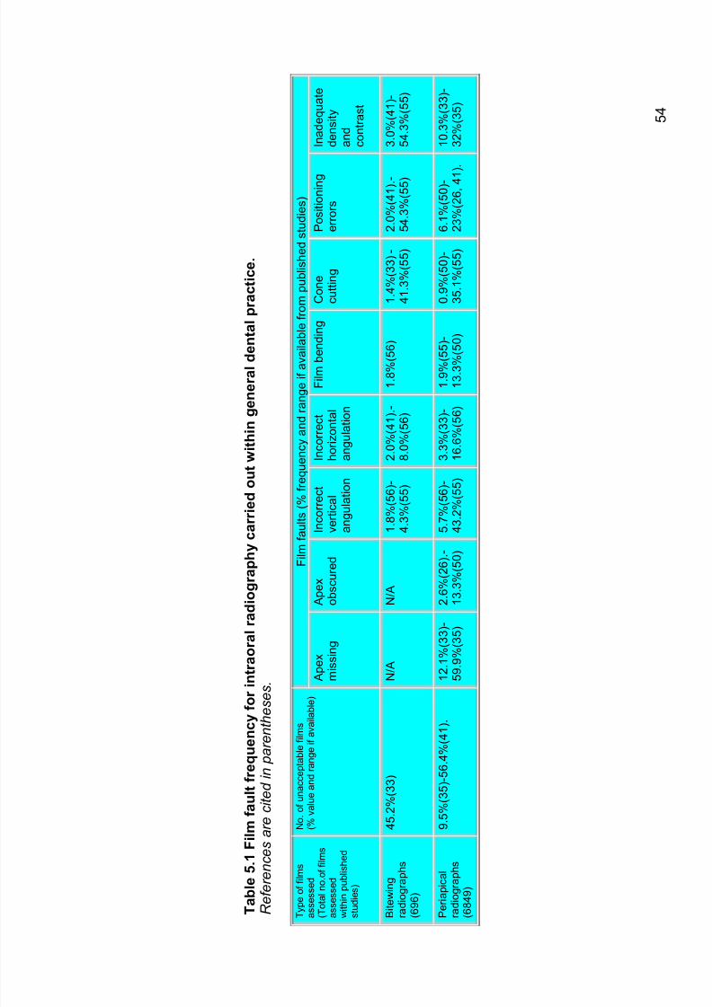
7/14/2019 136_en
http://slidepdf.com/reader/full/136en 58/120
5 4
T a b l e
5 . 1
F i l m f a
u l t f r e q u e n c y f o r i n t r a o r a l r a d i o g r a p h y c a
r r i e d o u t w i t h i n g e n e r a l d e
n t a l p r a c t i c e .
R e f e r e n c e s a r e c i t e d i n p a r e n t h e s
e s .
F i l m f a u
l t s ( % f r
e q u e n c y a n d r a n g e i f a v a i l a b l e f r o m p
u b l i s h e d s t u d i e s )
T y p e o f f i l m s
a s s e s s e d
( T o t a l n o . o
f f i l m s
a s s e s s e d
w i t h i n p u b l i s h e d
s t u d i e s )
N o . o f u n a c c e p t a b l e f i l m s
( % v
a l u e a n d r a n g e i f a v a i l a b l e )
A p e x
m i s s i n g
A p e x
o b s c u r e d
I n
c o r r e c t
v e r t i c a l
a n g u l a t i o n
I n c o r r e c t
h o r i z o n t a l
a n g u l a t i o n
F i l m b e
n d i n g
C o n e
c u t t i n g
P o s i t i o n i n g
e r r o r s
I n a d e q u a t e
d e n s i t y
a n d
c o n t r a s t
B i t e w i n g
r a d i o g r a
p h s
( 6 9 6 )
4 5 . 2
% ( 3 3 )
N / A
N / A
1 . 8
% ( 5 6 ) -
4 . 3
% ( 5 5 )
2 . 0
% ( 4 1 ) . -
8 . 0
% ( 5 6 )
1 . 8
% ( 5 6 )
1 . 4
% ( 3 3 ) -
4 1 . 3
% ( 5 5 )
2 . 0
% ( 4 1 ) . -
5 4 . 3
% ( 5 5 )
3 . 0
% ( 4 1 ) -
5 4 . 3
% ( 5 5 )
P e r i a p i c
a l
r a d i o g r a
p h s
( 6 8 4 9 )
9 . 5
% ( 3 5 ) - 5 6 . 4
% ( 4 1 ) .
1 2 . 1
% ( 3 3 ) -
5 9 . 9
% ( 3 5 )
2 . 6
% ( 2 6 ) . -
1 3 . 3
% ( 5 0 )
5 . 7
% ( 5 6 ) -
4 3 . 2
% ( 5 5 )
3 . 3
% ( 3 3 ) -
1 6 . 6
% ( 5 6 )
1 . 9
% ( 5 5 ) -
1 3 . 3
% ( 5 0 )
0 . 9
% ( 5 0 ) -
3 5 . 1
% ( 5 5 )
6 . 1
% ( 5 0 ) -
2 3 % ( 2 6 ,
4 1
) .
1 0 . 3
% ( 3 3 ) -
3 2 % ( 3 5 )
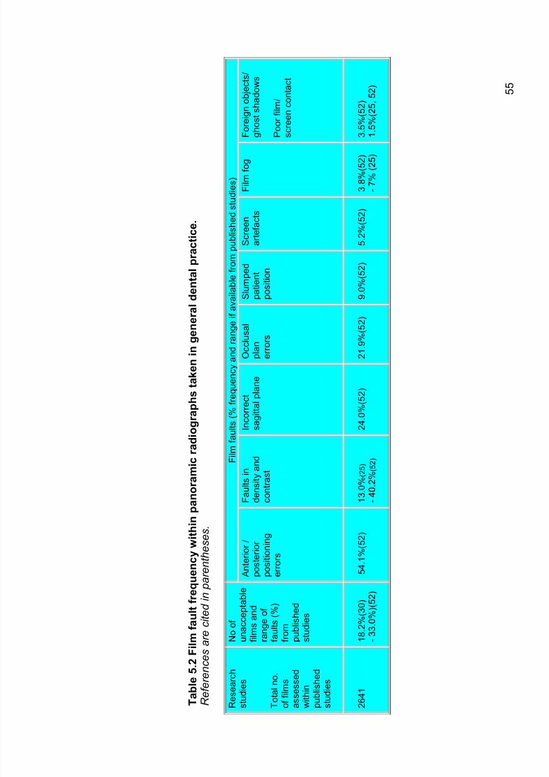
7/14/2019 136_en
http://slidepdf.com/reader/full/136en 59/120
5 5
T a b l e
5 . 2
F i l m f a
u l t f r e q u e n c y w
i t h i n p a n o r a m i c r a d i o g r a p
h s t a k e n i n g e n e r a l d e n t a l p r a c t i c e .
R e f e r e n c e s a r e c i t e d i n p a r e n t h e s
e s .
F i l m f a
u l t s ( % f r
e q u e n c y a n d r a n g e i f a v a i l a b l e f r o m p
u b l i s h e d s t u d i e s )
R e s e a r c h
s t u d i e s
T o t a l n o .
o f f i l m s
a s s e s s e d
w i t h i n
p u b l i s h e d
s t u d i e s
N o o f
u n a c c e p t a b l e
f i l m s a n d
r a n g e o f
f a u l t s ( % )
f r o m
p u b l i s h e d
s t u d i e s
A n t e r i o r /
p o s t e r i o r
p o s i t i o n i n g
e r r o r s
F a u l t s i n
d e n s i t y a n d
c o n t r a s t
I n c o r r e c t
s a g i t t a
l p l a n e
O c c l u s a l
p l a n
e r r o r s
S l u m p e
d
p a t i e n t
p o s i t i o n
S c r e e n
a r t e f a c t s
F i l m f o
g
F
o r e i g n o b j e c t s /
g
h o s t s h a d o w s
P
o o r f i l m /
s
c r e e n c o n t a c t
2 6 4 1
1 8 . 2
% ( 3 0 )
- 3 3 . 0
% ) ( 5 2 )
5 4 . 1
% ( 5
2 )
1 3 . 0
% ( 2 5 )
- 4 0 . 2
% ( 5 2 )
2 4 . 0 %
( 5 2 )
2 1 . 9
% ( 5 2 )
9 . 0
% ( 5 2 )
5 . 2
% ( 5 2 )
3 . 8
% ( 5 2 )
- 7 % ( 2
5 )
3
. 5 % ( 5 2 )
1
. 5 % ( 2 5 ,
5 2 )
7/14/2019 136_en
http://slidepdf.com/reader/full/136en 60/120
56
Section 5.9 shows some common problems that may occur in dentalradiography. It is essential that image quality be monitored on a regular basis.This should be done in two ways. First, the dentist at the chair side can bevigilant in examining radiographs as and when they are produced. To facilitatethis, reference images of good quality can be kept available for comparative
purposes. Second, the dentist and staff can conduct periodic audits of imagequality. Clinical audit requires assessment against a clearly defined set of Quality Standards.
Image quality can be simply assessed as ‘Excellent’ (no faults), ‘Acceptable’(some faults but not affecting image interpretation) and ‘Unacceptable’ (faultsleading to the radiograph being unsuitable for interpretation). However, simplylogging the proportions of radiographs in each category will not help inimproving quality. An important step is to record the reasons for grading aradiograph as being of unacceptable quality. The Quality Standards given inTables 5.3 to 5.6 provide a means of comparing radiographs against an ideal.
Other standards, analogous to those described in EUR 16260 (7) may alsohave been developed. Audit may reveal errors that are recurring frequentlyand thus point towards essential changes in practice.
5.2.1 Targets for radiographic quality Using the criteria given for film quality, the practitioner can implement a ‘rejectfilm analysis’. Assessment of rejected films allows the dentist to identify thecause of poor images.
Unacceptable films are those in which film quality departs significantly fromthe accepted Quality Standard, thereby, compromising or preventingdiagnosis and, in more extreme cases, negating the purpose for which the filmwas taken.
There can be no tolerable level of 'unacceptable' radiographs. However, inthe UK, a non-evidence based level 'not greater than 10%' for unacceptablefilms has been recommended as an achievable audit standard for primarydental care. This is an achievable target as rates of unacceptable films inhospital departments can be much lower (47). Obviously, as there will bewide inter-practitioner variation in the level of unacceptable films in primarydental care, a more realistic and achievable standard would be for each
dentist to achieve a 50% reduction in unacceptable films at each subsequentaudit session (46).
Recommendation 5B
As a minimum target, no greater than 10% of radiographs should be of unacceptable quality. The aim should be to reduce the proportion of unacceptable radiographs by 50% at each successive audit cycle.
C
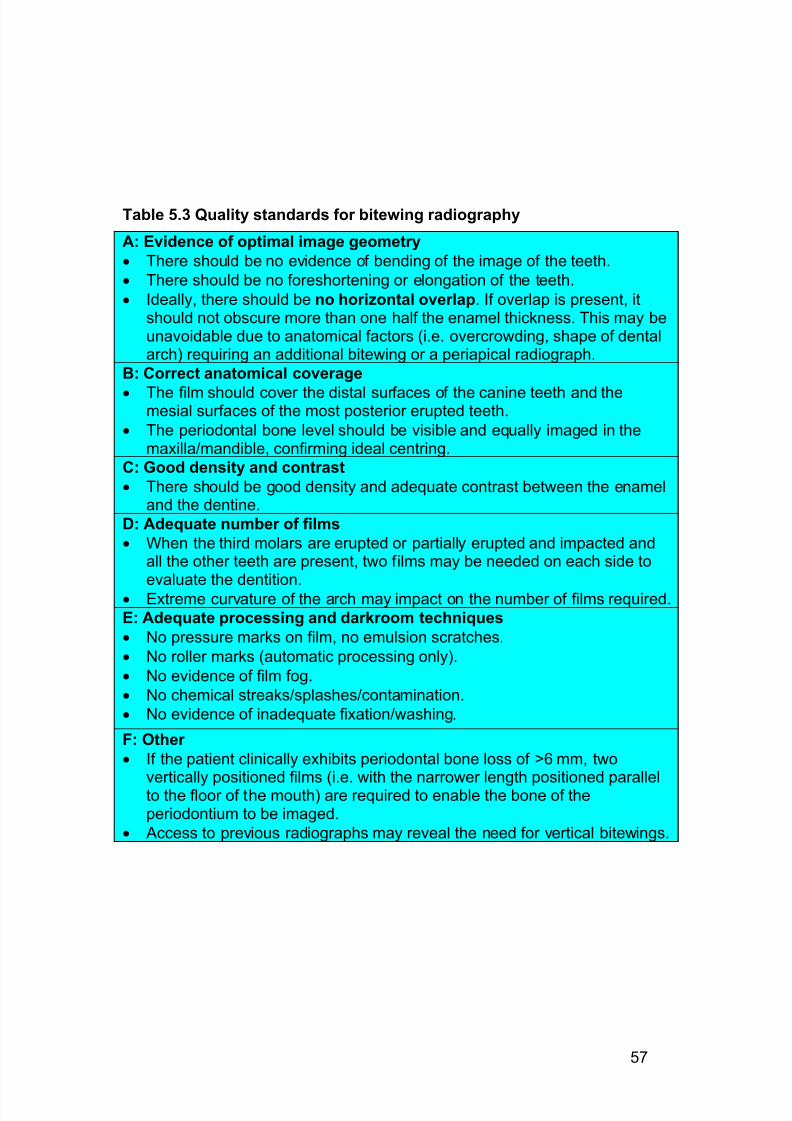
7/14/2019 136_en
http://slidepdf.com/reader/full/136en 61/120
57
Table 5.3 Quality standards for bitewing radiography
A: Evidence of optimal image geometry
· There should be no evidence of bending of the image of the teeth.
· There should be no foreshortening or elongation of the teeth.
· Ideally, there should be no horizontal overlap. If overlap is present, itshould not obscure more than one half the enamel thickness. This may beunavoidable due to anatomical factors (i.e. overcrowding, shape of dentalarch) requiring an additional bitewing or a periapical radiograph.
B: Correct anatomical coverage
· The film should cover the distal surfaces of the canine teeth and themesial surfaces of the most posterior erupted teeth.
· The periodontal bone level should be visible and equally imaged in themaxilla/mandible, confirming ideal centring.
C: Good density and contrast
· There should be good density and adequate contrast between the enameland the dentine.
D: Adequate number of films
· When the third molars are erupted or partially erupted and impacted andall the other teeth are present, two films may be needed on each side toevaluate the dentition.
· Extreme curvature of the arch may impact on the number of films required.
E: Adequate processing and darkroom techniques
· No pressure marks on film, no emulsion scratches.
· No roller marks (automatic processing only).
· No evidence of film fog.
· No chemical streaks/splashes/contamination.
· No evidence of inadequate fixation/washing.
F: Other
· If the patient clinically exhibits periodontal bone loss of >6 mm, twovertically positioned films (i.e. with the narrower length positioned parallelto the floor of the mouth) are required to enable the bone of theperiodontium to be imaged.
· Access to previous radiographs may reveal the need for vertical bitewings.
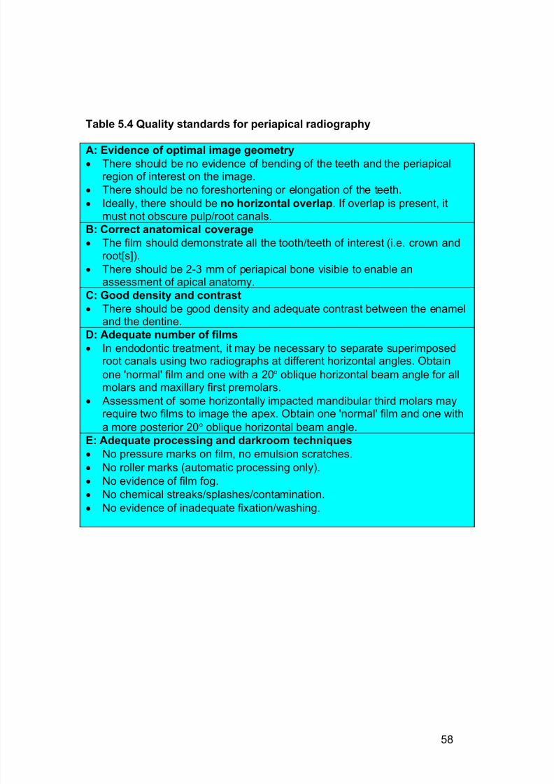
7/14/2019 136_en
http://slidepdf.com/reader/full/136en 62/120
58
Table 5.4 Quality standards for periapical radiography
A: Evidence of optimal image geometry
· There should be no evidence of bending of the teeth and the periapicalregion of interest on the image.
· There should be no foreshortening or elongation of the teeth.
· Ideally, there should be no horizontal overlap. If overlap is present, itmust not obscure pulp/root canals.
B: Correct anatomical coverage
· The film should demonstrate all the tooth/teeth of interest (i.e. crown androot[s]).
·
There should be 2-3 mm of periapical bone visible to enable anassessment of apical anatomy.
C: Good density and contrast
· There should be good density and adequate contrast between the enameland the dentine.
D: Adequate number of films
· In endodontic treatment, it may be necessary to separate superimposedroot canals using two radiographs at different horizontal angles. Obtain
one 'normal' film and one with a 20° oblique horizontal beam angle for allmolars and maxillary first premolars.
· Assessment of some horizontally impacted mandibular third molars may
require two films to image the apex. Obtain one 'normal' film and one witha more posterior 20° oblique horizontal beam angle.
E: Adequate processing and darkroom techniques
· No pressure marks on film, no emulsion scratches.
· No roller marks (automatic processing only).
· No evidence of film fog.
· No chemical streaks/splashes/contamination.
· No evidence of inadequate fixation/washing.
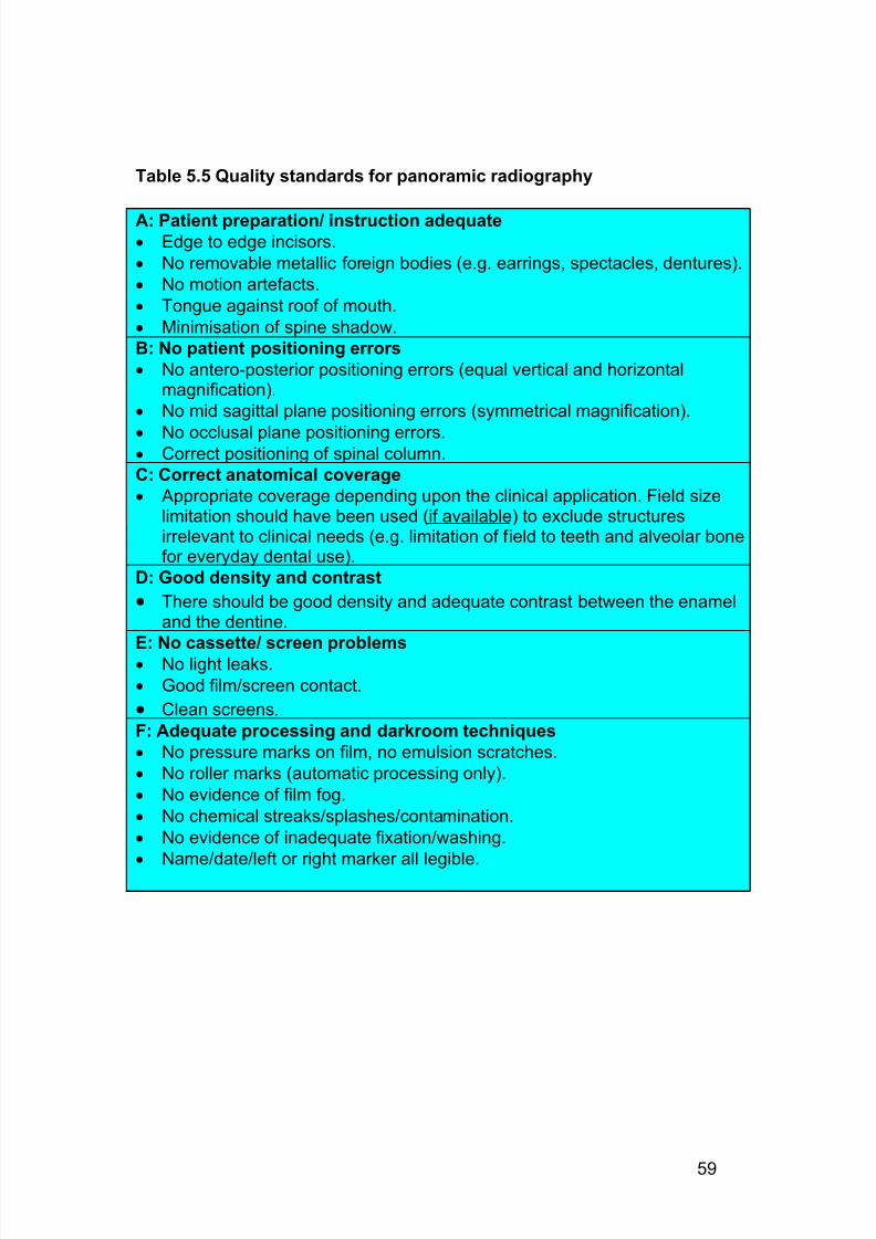
7/14/2019 136_en
http://slidepdf.com/reader/full/136en 63/120
59
Table 5.5 Quality standards for panoramic radiography
A: Patient preparation/ instruction adequate· Edge to edge incisors.
· No removable metallic foreign bodies (e.g. earrings, spectacles, dentures).
· No motion artefacts.
· Tongue against roof of mouth.
· Minimisation of spine shadow.
B: No patient positioning errors
· No antero-posterior positioning errors (equal vertical and horizontalmagnification).
· No mid sagittal plane positioning errors (symmetrical magnification).
· No occlusal plane positioning errors.· Correct positioning of spinal column.
C: Correct anatomical coverage
· Appropriate coverage depending upon the clinical application. Field sizelimitation should have been used (if available) to exclude structuresirrelevant to clinical needs (e.g. limitation of field to teeth and alveolar bonefor everyday dental use).
D: Good density and contrast
· There should be good density and adequate contrast between the enameland the dentine.
E: No cassette/ screen problems· No light leaks.
· Good film/screen contact.
· Clean screens.
F: Adequate processing and darkroom techniques
· No pressure marks on film, no emulsion scratches.
· No roller marks (automatic processing only).
· No evidence of film fog.
· No chemical streaks/splashes/contamination.
· No evidence of inadequate fixation/washing.
· Name/date/left or right marker all legible.

7/14/2019 136_en
http://slidepdf.com/reader/full/136en 64/120
60
Table 5.6: Quality standards for cephalometric radiography
A: Patient preparation/ instruction adequate
· Frankfort plane perpendicular to film.
· No sagittal plane positioning errors.
· No occlusal plane positioning errors
· Teeth in centric occlusion (stable and natural intercuspation).
· Lips relaxed.
B: No patient positioning errors
· No antero-posterior positioning errors.
· No mid sagittal plane positioning errors.
· No occlusal plane positioning errors.
· Exact matching of external auditory meati with positioning devices.
C: Correct anatomical coverage
· Visibility of all cephalometric tracing points required for the analysis.
· Visibility of all anterior skeletal and soft tissue structures.
D: Good density and contrast
E: No cassette/ screen problems
· No light leaks.
· Good film/screen contact.
· Clean screens.
F: Adequate processing and darkroom techniques
· No evidence of film fog.
· No evidence of chemical streaks/contamination.
· No evidence of inadequate fixation /washing.
· No evidence of screen damage/artifacts.
· No roller marks/pressure marks.
· Name and date legible.
7/14/2019 136_en
http://slidepdf.com/reader/full/136en 65/120
61
5.3 Practical radiographic technique
5.3.1 Intraoral radiography Section 6.9 shows some common problems in intraoral radiography. A parallelX-ray beam directed perpendicular to both the object being examined and the
film provides the best imaging geometry. This can be achieved for thecommon intraoral radiographic projections using:
· X-ray set with a ‘long’ open-ended PID
· Film holder with a beam-aiming device
The X-ray focus to skin distance should be at least 200 mm. This means thatthe X-ray beam is closer to parallelism than was seen with older X-ray setsusing shorter distances. The film holder itself should incorporate three keycomponents:
· Bite block
· Rigid backing to support the film· Extra-oral beam aiming device
The bite block helps to maintain correct film position relative to the teeth. Therigid backing limits the risk of film bending and resultant image distortion. Thebeam-aiming device ensures the ideal of a beam that is perpendicular to thefilm.
5.3.2 The paralleling techniqueThe paralleling technique requires that the X-ray film is positioned parallel withthe long axes of the teeth. The central ray of the X-ray beam passes at right
angles, i.e. perpendicular, to the tooth being imaged. In order to minimize magnification of the image and subsequent loss of imagesharpness, the technique uses an increased focal spot-to-object distanceensuring a more parallel X-ray beam is incident to the object and imagereceptor.
5.3.2.1 Advantages of the paralleling technique
Adopting the paralleling technique has many benefits for both the operator and patient:
· Minimal elongation/foreshortening/distortion
· An increased FSD reduces surface dose· An increased FSD improves image quality by reducing the penumbra
effect
· Reduction in distortional effects due to bending of the film/imagereceptor
The use of the paralleling technique along with film holding beam alignmentinstruments allows the operator to obtain images that have reproducibility andstandardisation. This allows the clinician to study longitudinal diseaseprogression and to assess accurately treatment outcomes (50).
7/14/2019 136_en
http://slidepdf.com/reader/full/136en 66/120
62
Recommendation 5 C
5.3.3 Panoramic radiography Research shows that patient positioning errors are frequent in carrying outpanoramic radiography in primary dental care (25, 30, 52).
It is extremely important that dentists understand how their panoramicequipment works and that they can effectively ‘trouble-shoot’ problems.Section 5.9 shows some common errors of positioning and technique in
panoramic radiography. Technique is facilitated when equipmentincorporates patient positioning aids and uses light beams.
Recommendation 5 D
5.3.4 Cephalometric radiography It is intrinsic to the purposes of cephalometric radiography that images arereproducible. This requires a fixed X-ray source/patient/image receptor relationship. It is unacceptable to perform cephalometric radiography withouta cephalostat to fix head position. Most dentists working in primary dentalcare would use an integrated panoramic/cephalometric radiographic system.However, some may use a dental X-ray set as the source. The large distance
of patient to X-ray source required in cephalometry, is such that using anunmodified dental X-ray set would lead to an unacceptably large X-ray fieldand excessive radiation dose. Therefore, dental X-ray equipment must besuitably modified to ensure correct collimation and alignment bydirectinvolvement of a medical physics expert.
Recommendation 5 E
A cephalostat and a fixed X-ray source/patient/image receptor relationshipshould be used for cephalometric radiography.
B
Accurate positioning in panoramic radiography can be facilitated by usingall available positioning aids correctly and by adequate training of users.When buying new equipment it is important to ensure that light beampositioning aids are included.
B
Film holders incorporating beam-aiming devices using the parallelingtechnique and facilitating rectangular collimation should be used for intraoral radiography wherever possible.
B
7/14/2019 136_en
http://slidepdf.com/reader/full/136en 67/120
63
Visualisation of the soft tissue profile is needed on cephalometric radiographs.This can be done either by using a suitable wedge filter in front of the patient(preferred option from a dose reduction standpoint) or cassette, or by fittinggraduated intensifying screens within the film cassette.
5.4 Patient dose and X-ray equipment - Diagnostic Reference Levels An objective of the QA programme is to ensure doses are kept as low asreasonably achievable. It is, therefore necessary to ensure that patient dosesare monitored on a regular basis.
Diagnostic Reference Levels (DRLs) are patient dose levels for medicaldiagnostic exposure that can be used as investigation levels as part of thisoptimisation process. The International Commission on RadiologicalProtection (ICRP) first introduced the term diagnostic reference level in 1996(13) and has produced further advice (15). The requirement for DRLs hasbeen included within the European Medical Exposures Directive (3) and theEC has produced further guidance on the setting of DRLs (5).
Essentially, the aim of DRLs is to provide reference levels of easilymeasurable patient dose quantities for facilities to compare their averagedoses against. DRLs are not intended to be applied to individual exposures of individual patients (5). They can be set at a range of levels, i.e. European,national, regional, or local level. The intention is to indicate an upper level of acceptability for current normal radiological practice. The use of DRLs is “asimple means of identifying those situations well away from the optimumwhere corrective action is most urgently needed” (61).
Having an average dose below a relevant DRL gives some confirmation thatpatient doses in a particular facility are reasonably in line with other facilities.It does not necessarily indicate that dose is optimised. However, dosesconsistently above a DRL would definitely indicate that patient dose is not inline with the ALARA principle and that action should be taken to reduce dose.
The concept of DRLs is now well established within general hospitalradiology. The most usual method of setting a DRL is to base it on the thirdquartile of field measurements performed in a large number of establishments(5, 21, 62). Consequently, DRLs are based on current practice across a wide
range of different establishment, not on results from a select group of facilitieswith a high level of equipment and expertise.
European wide DRLs have not, so far, been promulgated for dentalprojections, although some European countries have established nationaldental DRLs (or equivalent) (22, 36, 45).
5.4.1 Intraoral
5.4.1.1 Dose quantities
The majority of surveys of patient dose in intraoral film radiography have
measured the dose in air or tissue at the end of the spacer cone (usuallyreferred to as entrance surface dose (ESD) although often it is an
7/14/2019 136_en
http://slidepdf.com/reader/full/136en 68/120
64
underestimate as backscatter from within the head is not always included).This is a relatively simple measure, readily performed by a medical physicsexpert (MPE). The MPE might visit the practice to perform the measurementusing some form of electronic dosemeter, alternatively either a film or thermoluminescent device dosemeter (TLD) package can be provided by post
for exposure by the dental practice staff. Germany (36) currently requires themeasurement of dose at depth. Whilst being a better indicator of effectivedose than entrance dose, this will not pick up the significant difference in skindose caused by using low kV equipment.
5.4.1.2 European data
A summary of dose surveys and current national DRLs for European andNorth American data is given in table 5.7. It is evident that a wide variation indose exists from practice to practice, with many surveys recording ESD atindividual practices above 20 mGy. The distributions of the results tend to beskewed with just a few outliers at the higher doses (31, 37, 45).
It can be seen that the mean levels tend to be lower for the most recentlyperformed surveys, probably reflecting the change from D- to E-speed filmand the greater use of 60-70 kV X-ray equipment.
5.4.1.3 Suggested values
The majority of patient intraoral dose surveys have been in terms of cone enddose, measured in air, for average adult settings. Unfortunately, a range of projections has been chosen. The UK data is by far the most comprehensivesurvey of actual practice in Europe and the recommended DRL has beenbased on this. At this stage it is not suggested that the lower value currentlybeing promoted within the UK be adopted as it is clear that within Europe
there is significant variation in practice; for example the Danish, Greek andPortuguese surveys also encompassed a significant number of X-ray sets andindicate higher levels within these countries.
Recommendation 5 F
5.4.2 Digital equipment
Intraoral digital detectors are generally capable of operating optimally at lower doses compared with film (see Section 4.4.3.) DRLs derived from survey of practices using film will be higher than those achievable using digitalradiography. When individual practices using digital sensors compare dosesto European or national DRLs, the expected difference between film anddigital sensor should be borne in mind.
Digital detectors, in particular phosphor plate systems, have very large
latitude. Higher doses than necessary may be used without the operator being warned by a dark image (29). For this reason, it is of particular
The Medical Directive requires the establishment of DRLs.The working party recommends a DRL of 4 mGy absorbed dose in air measured at the end of the spacer cone for a standard maxillary molar projection.
ED
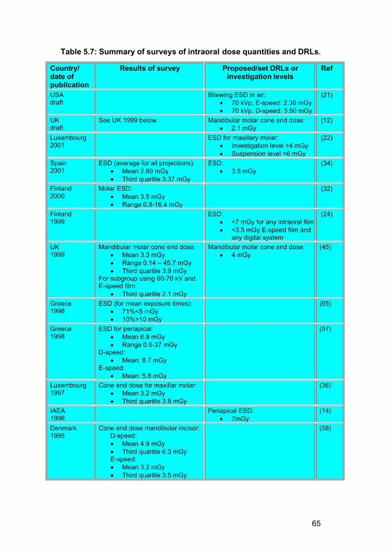
7/14/2019 136_en
http://slidepdf.com/reader/full/136en 69/120
65
Table 5.7: Summary of surveys of intraoral dose quantities and DRLs.
Country/date of publication
Results of survey Proposed/set DRLs or investigation levels
Ref
USAdraft Bitewing ESD in air:· 70 kVp, E-speed: 2.30 mGy
· 70 kVp, D-speed: 3.50 mGy
(21)
UKdraft
See UK 1999 below Mandibular molar cone end dose:
· 2.1 mGy
(12)
Luxembourg2001
ESD for maxillary molar:
· Investigation level >4 mGy
· Suspension level >6 mGy
(22)
Spain2001
ESD (average for all projections):
· Mean 2.89 mGy
· Third quartile 3.37 mGy
ESD:
· 3.5 mGy
(34)
Finland
2000
Molar ESD:
· Mean 3.5 mGy· Range 0.8-16.4 mGy
(32)
Finland1999
ESD:
· <7 mGy for any intraoral film
· <3.5 mGy E-speed film andany digital system
(24)
UK1999
Mandibular molar cone end dose:
· Mean 3.3 mGy
· Range 0.14 – 45.7 mGy
· Third quartile 3.9 mGyFor subgroup using 60-70 kV andE-speed film:
· Third quartile 2.1 mGy
Mandibular molar cone end dose:
· 4 mGy
(45)
Greece1998
ESD (for mean exposure times):
· 71%<5 mGy
· 10%>10 mGy
(65)
Greece1998
ESD for periapical:
· Mean 6.9 mGy
· Range 0.6-37 mGyD-speed:
· Mean: 8.7 mGyE-speed:
· Mean: 5.8 mGy
(57)
Luxembourg1997
Cone end dose for maxillar molar:
· Mean 3.2 mGy
· Third quartile 3.8 mGy
(36)
IAEA1996
Periapical ESD:
· 7mGy
(14)
Denmark1995
Cone end dose mandibular incisor:D-speed:
· Mean 4.9 mGy
· Third quartile 6.3 mGyE-speed:
· Mean 3.2 mGy
· Third quartile 3.5 mGy
(58)
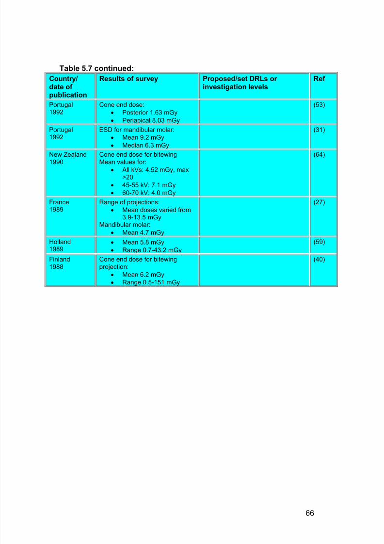
7/14/2019 136_en
http://slidepdf.com/reader/full/136en 70/120
66
Table 5.7 continued:
Country/date of
publication
Results of survey Proposed/set DRLs or investigation levels
Ref
Portugal1992
Cone end dose:
· Posterior 1.63 mGy
· Periapical 8.03 mGy
(53)
Portugal1992
ESD for mandibular molar:
· Mean 9.2 mGy
· Median 6.3 mGy
(31)
New Zealand1990
Cone end dose for bitewingMean values for:
· All kVs: 4.52 mGy, max>20
· 45-55 kV: 7.1 mGy
· 60-70 kV: 4.0 mGy
(64)
France1989
Range of projections:
· Mean doses varied from3.9-13.5 mGy
Mandibular molar:
· Mean 4.7 mGy
(27)
Holland1989
· Mean 5.8 mGy
· Range 0.7-43.2 mGy
(59)
Finland1988
Cone end dose for bitewingprojection:
· Mean 6.2 mGy
· Range 0.5-151 mGy
(40)
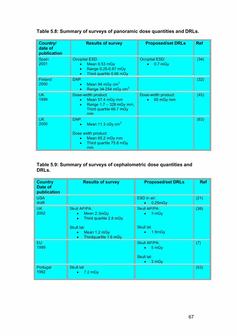
7/14/2019 136_en
http://slidepdf.com/reader/full/136en 71/120
67
Table 5.8: Summary of surveys of panoramic dose quantities and DRLs.
Country/date of publication
Results of survey Proposed/set DRLs Ref
Spain2001
Occipital ESD:· Mean 0.53 mGy
· Range 0.25-0.87 mGy
· Third quartile 0.66 mGy
Occipital ESD:· 0.7 mGy
(34)
Finland2000
DAP:
· Mean 94 mGy cm2
· Range 34-254 mGy cm2
(32)
UK1999
Dose-width product:
· Mean 57.4 mGy mm
· Range 1.7 – 328 mGy mm,Third quartile 66.7 mGymm
Dose-width product:
· 65 mGy mm
(45)
UK2000
DAP:
· Mean 11.3 cGy cm2
Dose width product:
· Mean 65.2 mGy mm
· Third quartile 75.8 mGymm
(63)
Table 5.9: Summary of surveys of cephalometric dose quantities andDRLs.
CountryDate of publication
Results of survey Proposed/set DRLs Ref
USAdraft
ESD in air:
· 0.25mGy
(21)
UK2002
Skull AP/PA:
· Mean 2.3mGy
· Third quartile 2.8 mGy
Skull lat:
· Mean 1.2 mGy
· Thirdquartile 1.6 mGy
Skull AP/PA:
· 3 mGy
Skull lat:
· 1.5mGy
(38)
EU1999
Skull AP/PA:
· 5 mGy
Skull lat:
· 3 mGy
(7)
Portugal1992
Skull lat:
· 7.2 mGy
(53)
7/14/2019 136_en
http://slidepdf.com/reader/full/136en 72/120
68
importance that users of digital detectors monitor dose levels to providecontinued assurance that they are being used optimally.
5.4.3 Panoramic radiography
5.4.3.1 Dose quantities
The establishment of DRLs for panoramic radiography is not as welldeveloped as for intraoral film radiography. The UK have adopted the conceptof dose width product i.e. the maximum dose at the film cassette slit multipliedby the width of the beam at the slit (45) measured without a patient. However,the methodology has not been well defined and significant differences inresults occur due to the different measurement methods adopted (63). Thiswill be particularly true for the newer panoramic units with narrow slits and anon-uniform dose profile across the slit. Other approaches suggested havebeen to use the product of dose and beam area as measured by a dose areaproduct (DAP) meter or TLD stack (63) or to perform surface dose
measurements on patients (34). This latter approach is thought to be of limited value as the surface dose distribution varies widely dependent of thetype of panoramic unit in use (44) and will not give a good representation of the distribution of depth dose within the head.
5.4.3.2 European data
A summary of the dose surveys for panoramic radiography is given in Table5.8. This indicates a scarcity of data and no clear agreement on approach.The working party feels unable to recommend a DRL at this stage.
Recommendation 5 G
5.4.4 Cephalometry (teleradiography)5.4.4.1 Dose quantities
Although a European DRL does exist for both PA and lateral skull radiographyusing ESD measurements (5), specific DRLs for cephalometry have yet to beestablished. Limited survey data exists for cephalometry as indicated in Table5.9. Given the absence of the anti-scatter grid and the longer FFD employedin cephalometry, it is likely that any entrance surface dose would be lower than for skull radiography (usual FFD of 1 m). Differences might also beexpected due to different contrast requirement requiring different kV selection.Finally, it is normally considered good practice to limit the field for cephalometry (see Section 4.3.3.). Although this will make little difference to
The working party recommends that further work be carried out onestablishing a measurement method (probably adopting the DAPapproach) for panoramic dosemetry and to undertake further fieldmeasurements so that a European DRL can be adopted.
ED
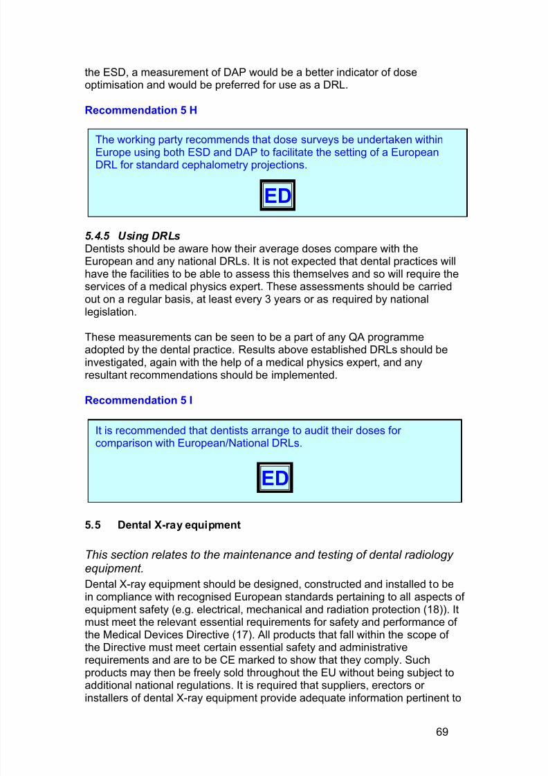
7/14/2019 136_en
http://slidepdf.com/reader/full/136en 73/120
69
the ESD, a measurement of DAP would be a better indicator of doseoptimisation and would be preferred for use as a DRL.
Recommendation 5 H
5.4.5 Using DRLsDentists should be aware how their average doses compare with theEuropean and any national DRLs. It is not expected that dental practices will
have the facilities to be able to assess this themselves and so will require theservices of a medical physics expert. These assessments should be carriedout on a regular basis, at least every 3 years or as required by nationallegislation.
These measurements can be seen to be a part of any QA programmeadopted by the dental practice. Results above established DRLs should beinvestigated, again with the help of a medical physics expert, and anyresultant recommendations should be implemented.
Recommendation 5 I
5.5 Dental X-ray equipment
This section relates to the maintenance and testing of dental radiology equipment.
Dental X-ray equipment should be designed, constructed and installed to bein compliance with recognised European standards pertaining to all aspects of equipment safety (e.g. electrical, mechanical and radiation protection (18)). Itmust meet the relevant essential requirements for safety and performance of the Medical Devices Directive (17). All products that fall within the scope of the Directive must meet certain essential safety and administrativerequirements and are to be CE marked to show that they comply. Suchproducts may then be freely sold throughout the EU without being subject toadditional national regulations. It is required that suppliers, erectors or installers of dental X-ray equipment provide adequate information pertinent to
It is recommended that dentists arrange to audit their doses for comparison with European/National DRLs.
ED
The working party recommends that dose surveys be undertaken withinEurope using both ESD and DAP to facilitate the setting of a EuropeanDRL for standard cephalometry projections.
ED
7/14/2019 136_en
http://slidepdf.com/reader/full/136en 74/120
70
the proper use, testing and maintenance of the equipment. In some member states there maybe further requirements relating to the supply of X-rayequipment.
In addition, the European Council Directives (2, 3) covering the use of ionising
radiation (see Chapter 1), place requirements on equipment owners to ensureequipment is tested so that the safety of both staff using the equipment andpatients undergoing diagnosis is optimised. The overall aim being to ensurethat dose to both staff and patients is kept as low as reasonably achievable.
5.5.1. Maintenance and testing It is essential that the features of dental X-ray equipment pertaining to theradiation safety of both users and patients be correctly maintained. To ensurethis, the equipment needs to be in good mechanical and electrical order.Regular maintenance and associated checks should be performed inaccordance with the recommendations of the manufacturer, the supplier, and
the qualified expert/medical physics expert. As well as the actual X-rayequipment, it should be remembered that automatic processors should besubject to a regular maintenance programme to ensure that they areoperating optimally as this has a direct effect on patient dose.
Dental X-ray equipment should be subject to the following inspections/tests(2, 3):
· Critical examination of plans for installation from the point of view of radiation safety of staff and members of the public (2)
· Acceptance test – performed prior to the equipment’s use in clinical
practice (2, 3)· Routine tests – these should be performed at regular intervals andfollowing any significant maintenance procedure (2, 3)
The exact arrangements for carrying out these tests on dental X-rayequipment and the criteria for remedial action vary from country to countrywithin the EU dependent on local legislative requirements and guidance.Qualified experts or medical physics experts should normally be involved.European criteria of acceptability have been established for intraoralradiography units and it is also recommended that the European criteria for general radiographic units can be applied to cephalometric units (4). In
general, there is a significant level of agreement with regard to the mainfeatures to be tested and criteria of acceptability (1, 11, 19, 20, 23, 24).
5.5.2. Critical examinationThe plans for the installation of a dental X-ray set should be critically reviewedby a qualified expert (or other approved body dependent on localarrangements) to ensure that all aspects of radiation safety for both practicestaff and members of the public have been considered (see Chapter 6). Inparticular, the following aspects need evaluation(11):
· Location, with particular attention to the points outlined in Chapter 6
·Protection provided to adjacent areas
· The operator’s position
7/14/2019 136_en
http://slidepdf.com/reader/full/136en 75/120
71
· The room’s warning signals, if appropriate
· The equipment’s warning signals· There should be a functioning indicator light on the control panel
to show that the mains is switched on indicating that theequipment is in a state of readiness to emit radiation.
· A warning light must be fitted to the equipment that provides aclear and visible indication to the operator that an exposure istaking place. This should be triggered only when there is to be acommencement and termination of radiation emission.
· The exposure control· If more than one X-ray set is sited in the same room, it should
not be possible for an operator either to inadvertently energisethe incorrect X-ray set or to accidentally cause irradiation topersons in another part of the room. If the arrangement is suchthat from a single location it is possible to start the production of X-rays from more than one X-ray tube, then it is advised thateach tube be fitted with a warning light that operates to alert thatthe tube is selected to emit X-rays.
· Corroboration of adequate equipment radiation protection and safetyfeatures (e.g. beam dimensions and alignment, beam filtration andtimer operation)
· Any other safety systems fitted on the equipment (e.g. safety cut-outswitches on panoramic equipment). This should also include allmechanical and electrical systems whose malfunction could affectradiation safety (e.g. rotational movement and braking on panoramicequipment, suitable counterbalance mechanisms on arms supporting
intra-oral X-ray tubes)
5.5.3. Acceptance test Prior to the equipment being introduced into clinical use, an acceptance testshould be carried out (2, 3) . The essential content of the acceptance test isthe same as for the critical examination. In addition, it should determine thatthe equipment operates properly within agreed performance parameters (e.g.operating potential, X-ray output, timer, accuracy) and provide baseline datafor comparison against during routine testing throughout the life of theequipment.
The acceptance test should also consist of measurements to assess typicalpatient doses. It is advised that a representative patient dose be calculatedand compared with an appropriate European, national or local DRL (seeSection 5.4).
Tests of equipment function should be carried out in a consistent manner,methods being based on international (8-10) and national guidance (54).
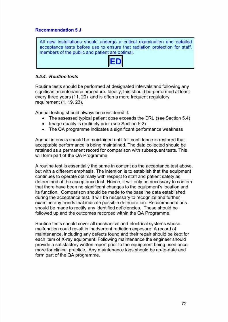
7/14/2019 136_en
http://slidepdf.com/reader/full/136en 76/120
72
Recommendation 5 J
5.5.4. Routine tests
Routine tests should be performed at designated intervals and following anysignificant maintenance procedure. Ideally, this should be performed at leastevery three years (11, 20) and is often a more frequent regulatoryrequirement (1, 19, 23).
Annual testing should always be considered if:· The assessed typical patient dose exceeds the DRL (see Section 5.4)
· Image quality is routinely poor (see Section 5.2)
· The QA programme indicates a significant performance weakness
Annual intervals should be maintained until full confidence is restored thatacceptable performance is being maintained. The data collected should beretained as a permanent record for comparison with subsequent tests. Thiswill form part of the QA Programme.
A routine test is essentially the same in content as the acceptance test above,but with a different emphasis. The intention is to establish that the equipmentcontinues to operate optimally with respect to staff and patient safety asdetermined at the acceptance test. Hence, it will only be necessary to confirmthat there have been no significant changes to the equipment’s location andits function. Comparison should be made to the baseline data establishedduring the acceptance test. It will be necessary to recognize and further examine any trends that indicate possible deterioration. Recommendationsshould be made to rectify any identified deficiencies. These should befollowed up and the outcomes recorded within the QA Programme.
Routine tests should cover all mechanical and electrical systems whosemalfunction could result in inadvertent radiation exposure. A record of maintenance, including any defects found and their repair should be kept for each item of X-ray equipment. Following maintenance the engineer shouldprovide a satisfactory written report prior to the equipment being used oncemore for clinical practice. Any maintenance logs should be up-to-date andform part of the QA programme.
All new installations should undergo a critical examination and detailedacceptance tests before use to ensure that radiation protection for staff,members of the public and patient are optimal.
ED
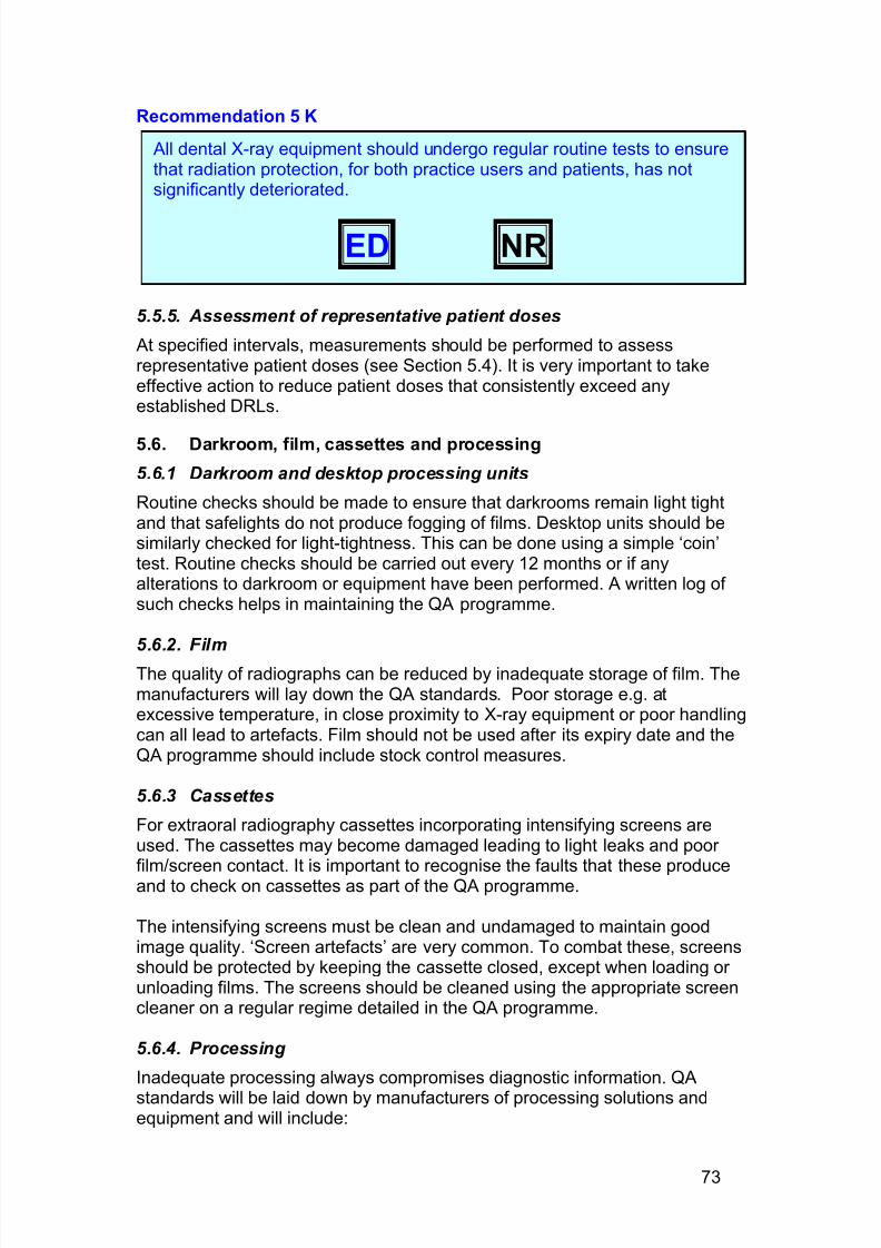
7/14/2019 136_en
http://slidepdf.com/reader/full/136en 77/120
73
Recommendation 5 K
5.5.5. Assessment of representative patient doses
At specified intervals, measurements should be performed to assessrepresentative patient doses (see Section 5.4). It is very important to takeeffective action to reduce patient doses that consistently exceed anyestablished DRLs.
5.6. Darkroom, film, cassettes and processing
5.6.1 Darkroom and desktop processing units
Routine checks should be made to ensure that darkrooms remain light tightand that safelights do not produce fogging of films. Desktop units should besimilarly checked for light-tightness. This can be done using a simple ‘coin’test. Routine checks should be carried out every 12 months or if anyalterations to darkroom or equipment have been performed. A written log of such checks helps in maintaining the QA programme.
5.6.2. Film
The quality of radiographs can be reduced by inadequate storage of film. Themanufacturers will lay down the QA standards. Poor storage e.g. atexcessive temperature, in close proximity to X-ray equipment or poor handlingcan all lead to artefacts. Film should not be used after its expiry date and theQA programme should include stock control measures.
5.6.3 Cassettes
For extraoral radiography cassettes incorporating intensifying screens areused. The cassettes may become damaged leading to light leaks and poor
film/screen contact. It is important to recognise the faults that these produceand to check on cassettes as part of the QA programme.
The intensifying screens must be clean and undamaged to maintain goodimage quality. ‘Screen artefacts’ are very common. To combat these, screensshould be protected by keeping the cassette closed, except when loading or unloading films. The screens should be cleaned using the appropriate screencleaner on a regular regime detailed in the QA programme.
5.6.4. Processing
Inadequate processing always compromises diagnostic information. QA
standards will be laid down by manufacturers of processing solutions andequipment and will include:
All dental X-ray equipment should undergo regular routine tests to ensurethat radiation protection, for both practice users and patients, has notsignificantly deteriorated.
ED NR
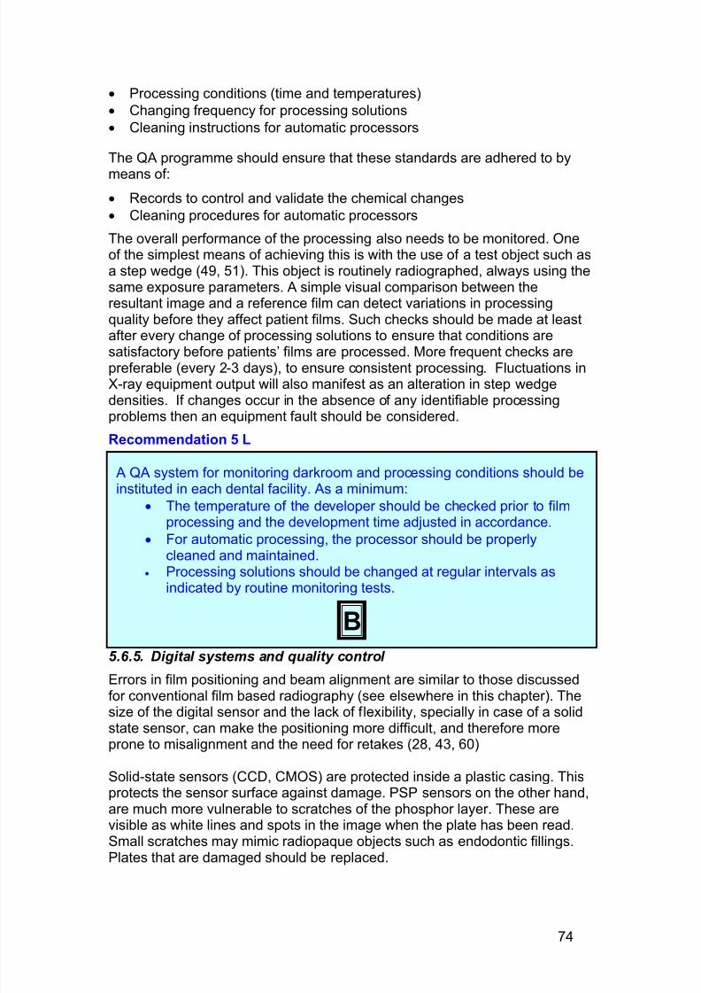
7/14/2019 136_en
http://slidepdf.com/reader/full/136en 78/120
74
· Processing conditions (time and temperatures)
· Changing frequency for processing solutions
· Cleaning instructions for automatic processors
The QA programme should ensure that these standards are adhered to by
means of:
· Records to control and validate the chemical changes
· Cleaning procedures for automatic processors
The overall performance of the processing also needs to be monitored. Oneof the simplest means of achieving this is with the use of a test object such asa step wedge (49, 51). This object is routinely radiographed, always using thesame exposure parameters. A simple visual comparison between theresultant image and a reference film can detect variations in processingquality before they affect patient films. Such checks should be made at leastafter every change of processing solutions to ensure that conditions are
satisfactory before patients’ films are processed. More frequent checks arepreferable (every 2-3 days), to ensure consistent processing. Fluctuations inX-ray equipment output will also manifest as an alteration in step wedgedensities. If changes occur in the absence of any identifiable processingproblems then an equipment fault should be considered.
Recommendation 5 L
5.6.5. Digital systems and quality control
Errors in film positioning and beam alignment are similar to those discussed
for conventional film based radiography (see elsewhere in this chapter). Thesize of the digital sensor and the lack of flexibility, specially in case of a solidstate sensor, can make the positioning more difficult, and therefore moreprone to misalignment and the need for retakes (28, 43, 60)
Solid-state sensors (CCD, CMOS) are protected inside a plastic casing. Thisprotects the sensor surface against damage. PSP sensors on the other hand,are much more vulnerable to scratches of the phosphor layer. These arevisible as white lines and spots in the image when the plate has been read.Small scratches may mimic radiopaque objects such as endodontic fillings.Plates that are damaged should be replaced.
A QA system for monitoring darkroom and processing conditions should beinstituted in each dental facility. As a minimum:
· The temperature of the developer should be checked prior to film
processing and the development time adjusted in accordance.· For automatic processing, the processor should be properly
cleaned and maintained.· Processing solutions should be changed at regular intervals as
indicated by routine monitoring tests.
B
7/14/2019 136_en
http://slidepdf.com/reader/full/136en 79/120
75
Plates should not be kept in the protective envelope for a long period beforebeing used. Cosmic radiation will reach the phosphor surface and transfer energy to electrons. This will result in ‘noise’ visible in the final image as blackspots. After the plates are exposed, they should be read as soon as possible.When the plates are kept for a longer, especially when they are exposed to
ambient light, the latent image will fade and the resulting image will lackcontrast and be noisier.
An important fact in the use of digital images is the quality of the monitor. Themonitor should have enough resolution to accommodate the current size of digital images. A resolution of 1024 x 768 pixels is the minimum, but larger ispreferable. In order to show the details at a magnification that is not toodifficult to interpret, the screen size of the monitor should be at least 17 inchfor a conventional monitor and 15 inch for a flat panel monitor. The gray levelresolution of the monitor should be set to at least ‘High Colour’ (16 bit), inorder to display small contrasts. Finally, brightness and contrast should be
checked and adjusted so that all gray values between black and white aredisplayed correctly. A method of back up for image data should be availableand used. If a dentist refers patients to colleagues, a means should beavailable to transfer the digital image (electronic transfer or hard-copy facility).
5.6.6. Viewing and reporting the radiographIdeal viewing conditions are essential in order to obtain maximum diagnosticinformation yield from the radiograph. This requires the use a dental light boxpositioned well away from strong ambient light, the peripheral masking of filmsto eliminate extraneous light and a method of magnifying the image by afactor of two. Commercially available film viewers are available which
combine peripheral masking and magnification. Research has shown that useof dedicated viewing conditions considerably improve diagnostic interpretationand yield (48). Performance levels and operating parameters for illuminatorshave been set and should be observed (16, 39). While checks on the lightoutput of viewing boxes is probably beyond the means of dental practices,routine cleaning of the viewing surface should be part of routine qualityprocedures.
All radiographs must be evaluated by the dentist and an appropriate report onthe radiological findings made. This reporting of films is also amenable toaudit.
5.7 Training
All those involved in radiology in dentistry should have received training that isadequate for their particular role. The roles can be divided into:
· The Holder : the person with legal responsibility under national law for agiven installation.
· The Practitioner : The dentist (or other health professional) who isentitled to take responsibility for an individual medical exposure inaccordance with national requirements.
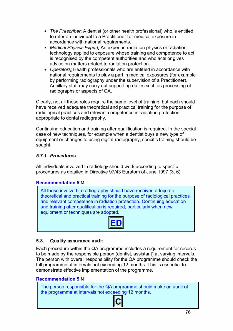
7/14/2019 136_en
http://slidepdf.com/reader/full/136en 80/120
76
· The Prescriber : A dentist (or other health professional) who is entitledto refer an individual to a Practitioner for medical exposure inaccordance with national requirements.
· Medical Physics Expert : An expert in radiation physics or radiationtechnology applied to exposure whose training and competence to act
is recognised by the competent authorities and who acts or givesadvice on matters related to radiation protection.
· Operators: Health professionals who are entitled in accordance withnational requirements to play a part in medical exposures (for exampleby performing radiography under the supervision of a Practitioner). Ancillary staff may carry out supporting duties such as processing of radiographs or aspects of QA.
Clearly, not all these roles require the same level of training, but each shouldhave received adequate theoretical and practical training for the purpose of radiological practices and relevant competence in radiation protectionappropriate to dental radiography.
Continuing education and training after qualification is required. In the specialcase of new techniques, for example when a dentist buys a new type of equipment or changes to using digital radiography, specific training should besought.
5.7.1 Procedures
All individuals involved in radiology should work according to specific
procedures as detailed in Directive 97/43 Euratom of June 1997 (3, 6).
Recommendation 5 M
5.8. Quality assurance audit
Each procedure within the QA programme includes a requirement for recordsto be made by the responsible person (dentist, assistant) at varying intervals.The person with overall responsibility for the QA programme should check thefull programme at intervals not exceeding 12 months. This is essential todemonstrate effective implementation of the programme.
Recommendation 5 N
The person responsible for the QA programme should make an audit of the programme at intervals not exceeding 12 months.
C
All those involved in radiography should have received adequatetheoretical and practical training for the purpose of radiological practicesand relevant competence in radiation protection. Continuing educationand training after qualification is required, particularly when newequipment or techniques are adopted.
ED
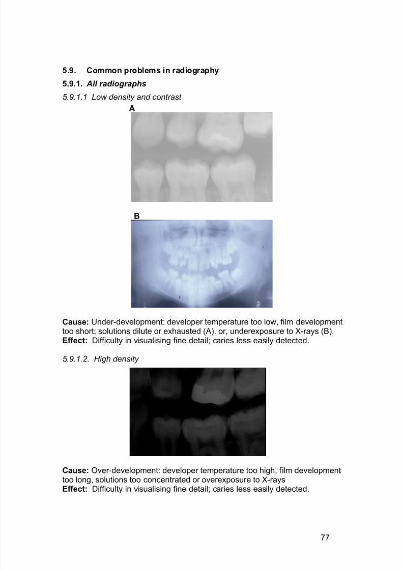
7/14/2019 136_en
http://slidepdf.com/reader/full/136en 81/120
77
5.9. Common problems in radiography
5.9.1. All radiographs
5.9.1.1 Low density and contrast A
B
Cause: Under-development: developer temperature too low, film developmenttoo short; solutions dilute or exhausted (A). or, underexposure to X-rays (B).Effect: Difficulty in visualising fine detail; caries less easily detected.
5.9.1.2. High density
Cause: Over-development: developer temperature too high, film developmenttoo long, solutions too concentrated or overexposure to X-raysEffect: Difficulty in visualising fine detail; caries less easily detected.
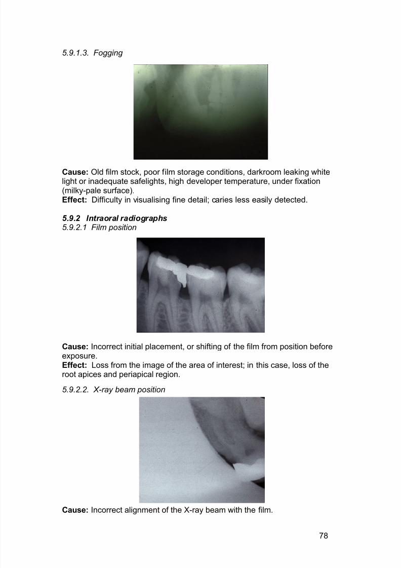
7/14/2019 136_en
http://slidepdf.com/reader/full/136en 82/120
78
5.9.1.3. Fogging
Cause: Old film stock, poor film storage conditions, darkroom leaking whitelight or inadequate safelights, high developer temperature, under fixation(milky-pale surface).
Effect: Difficulty in visualising fine detail; caries less easily detected.
5.9.2 Intraoral radiographs5.9.2.1 Film position
Cause: Incorrect initial placement, or shifting of the film from position beforeexposure.Effect: Loss from the image of the area of interest; in this case, loss of theroot apices and periapical region.
5.9.2.2. X-ray beam position
Cause: Incorrect alignment of the X-ray beam with the film.
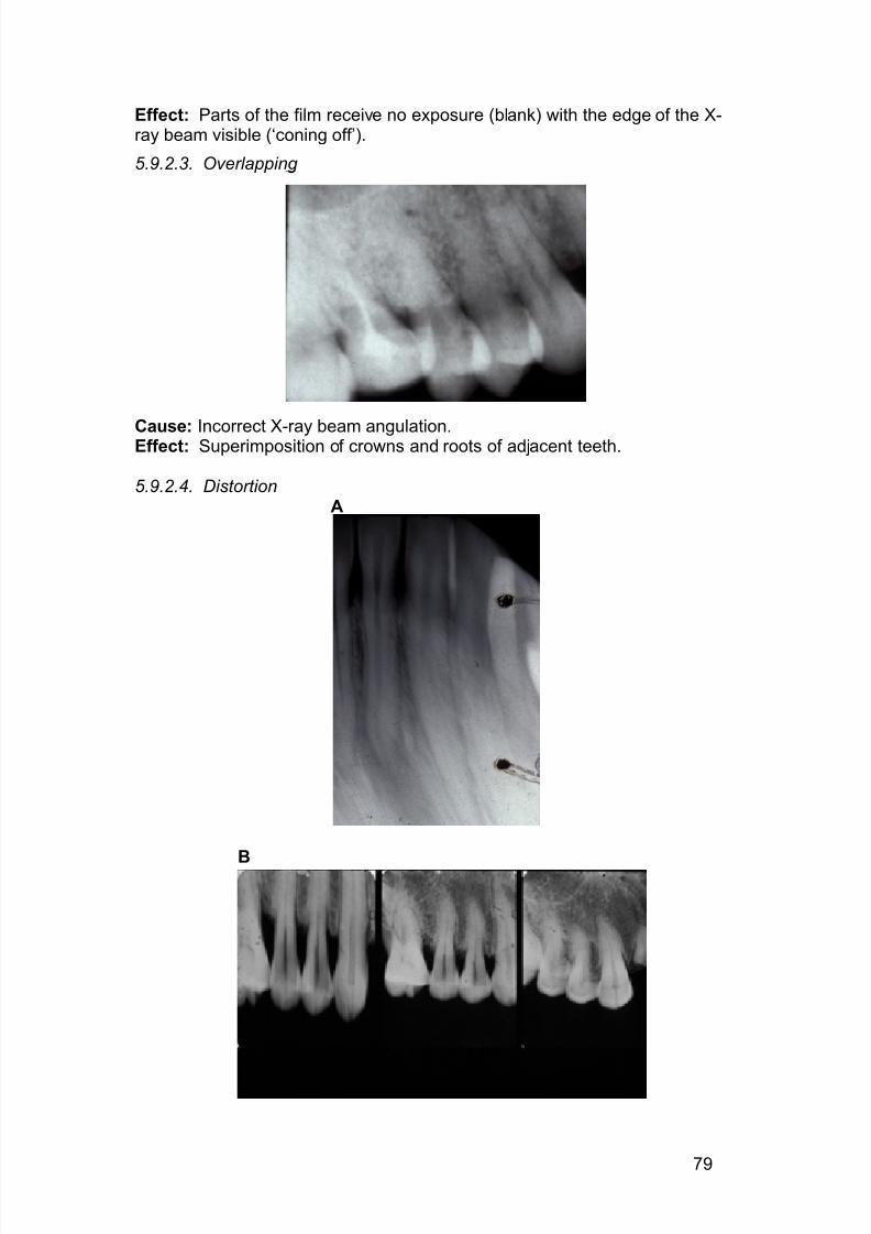
7/14/2019 136_en
http://slidepdf.com/reader/full/136en 83/120
79
Effect: Parts of the film receive no exposure (blank) with the edge of the X-ray beam visible (‘coning off’).
5.9.2.3. Overlapping
Cause: Incorrect X-ray beam angulation.Effect: Superimposition of crowns and roots of adjacent teeth.
5.9.2.4. DistortionA
B
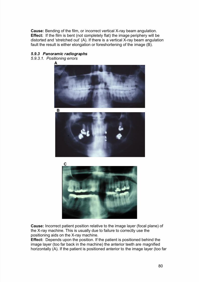
7/14/2019 136_en
http://slidepdf.com/reader/full/136en 84/120
80
Cause: Bending of the film, or incorrect vertical X-ray beam angulation.Effect: If the film is bent (not completely flat) the image periphery will bedistorted and ‘stretched out’ (A). If there is a vertical X-ray beam angulationfault the result is either elongation or foreshortening of the image (B).
5.9.3 Panoramic radiographs5.9.3.1. Positioning errors
A
B
C
Cause: Incorrect patient position relative to the image layer (focal plane) of the X-ray machine. This is usually due to failure to correctly use thepositioning aids on the X-ray machine.Effect: Depends upon the position. If the patient is positioned behind theimage layer (too far back in the machine) the anterior teeth are magnifiedhorizontally (A). If the patient is positioned anterior to the image layer (too far
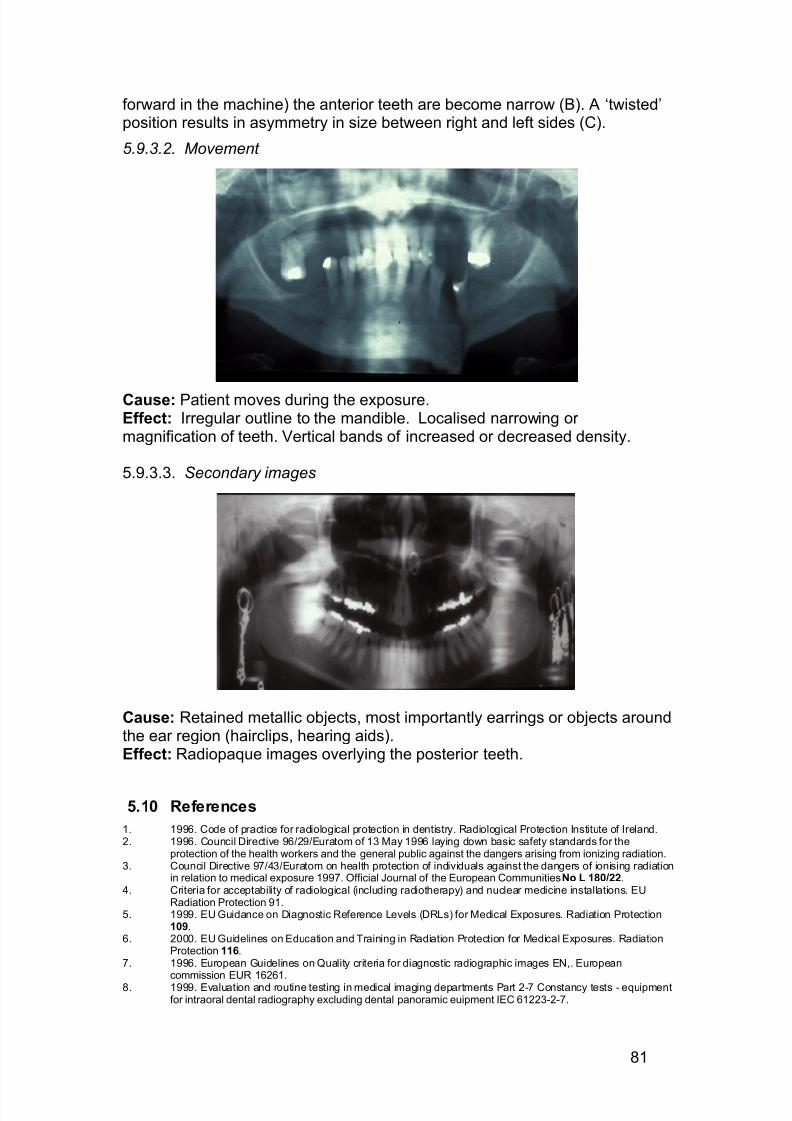
7/14/2019 136_en
http://slidepdf.com/reader/full/136en 85/120
81
forward in the machine) the anterior teeth are become narrow (B). A ‘twisted’position results in asymmetry in size between right and left sides (C).
5.9.3.2. Movement
Cause: Patient moves during the exposure.Effect: Irregular outline to the mandible. Localised narrowing or magnification of teeth. Vertical bands of increased or decreased density.
5.9.3.3. Secondary images
Cause: Retained metallic objects, most importantly earrings or objects aroundthe ear region (hairclips, hearing aids).Effect: Radiopaque images overlying the posterior teeth.
5.10 References
1. 1996. Code of practice for radiological protection in dentistry. Radiological Protection Institute of Ireland.2. 1996. Council Directive 96/29/Euratom of 13 May 1996 laying down basic safety standards for the
protection of the health workers and the general public against the dangers arising from ionizing radiation.3. Council Directive 97/43/Euratom on health protection of individuals against the dangers of ionising radiation
in relation to medical exposure 1997. Official Journal of the European Communities No L 180/22.4. Criteria for acceptability of radiological (including radiotherapy) and nuclear medicine installations. EU
Radiation Protection 91.5. 1999. EU Guidance on Diagnostic Reference Levels (DRLs) for Medical Exposures. Radiation Protection
109.6. 2000. EU Guidelines on Education and Training in Radiation Protection for Medical Exposures. Radiation
Protection 116.7. 1996. European Guidelines on Quality criteria for diagnostic radiographic images EN,. European
commission EUR 16261.8. 1999. Evaluation and routine testing in medical imaging departments Part 2-7 Constancy tests - equipment
for intraoral dental radiography excluding dental panoramic euipment IEC 61223-2-7.
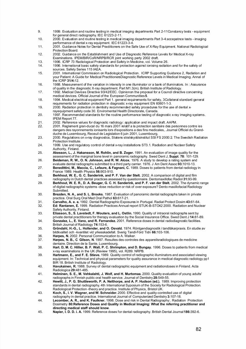
7/14/2019 136_en
http://slidepdf.com/reader/full/136en 86/120
82
9. 1999. Evaluation and routine testing in medical imaging departments Part 2-11Constancy tests - equipmentfor general direct radiography. IEC 61223-2-11.
10. 2000. Evaluation and routine testing in medical imaging departments Part 3-4:accepatnce tests - imagingperformance of dental x-ray equipment. IEC 61223-3-4.
11. 2001. Guidance Notes for Dental Practitioners on the Safe Use of X-Ray Equipment. National RadiologicalProtection Board.
12. 2002. Guidance on the Establishment and Use of Diagnostic Reference Levels for Medical X-rayExaminations. IPEM/BIR/CoR/NRPB/RCR joint working party 2002 draft.
13. 1996. ICRP 73 Radiological Protection and Safety in Medicine, vol. Volume 26.14. 1996. International basic safety standards for protection against ionising radiation and for the safety of
sources. Safety Series 115 IAEA.15. 2001. International Commission on Radiological Protection. ICRP Supporting Guidance 2, Radiation and
your Patient: A Guide for Medical PractitionersDiagnostic Reference Levels in Medical Imaging. Annal of the ICRP 31/4:12.
16. 1988. Measurement of the variation in intensity in one illuminator or a bank of illuminators. In : Assuranceof quality in the diagnostic X-ray department. Part M1.3(m). British Institute of Radiology.
17. 1992. Medical Devices Directive 93/42/EEC. Opinionon the proposal for a Council directive concerningmedical devices. Official Journal of the European Communities 5.
18. 1994. Medical electrical equipment Part 1. general requirements for safety, 3Collateral standard:generalrequirements for radiation protection in diagnostic x-ray equipment EN 60601-1-3.
19. 2000. Radiation protection in dentistry recommended safety procedures for the use of dental x-rayequipment safety code 30. Enviromental Health Directorate, Canada.
20. 1997. Recommended standards for the routine performance testing of diagnostic x-ray imaging systems.IPEM Report 77.
21. 2002. Reference values for diagnostic radiology: application and impact draft. AAPM.22. 2001. Reglement gran-ducal du 16 mars 2001 relatif a la protection sanitaire des personnes contre les
dangers des rayonnements ionisants lors d'expositions a des fins medicales,. Journal Officiel du Grand-duche de Luxembourg, Receuil de Legislation 6 juin 2001, Luxembourg.
23. 2000. Regulations on x-ray diagnostics, Statens stralskyddsinstitut SSI FS 2000:2. The Swedish RadiationProtection Institute.
24. 1999. Use and regulatory control of dental x-ray installations ST3.1. Radiation and Nuclaer Safety Authority, Finland.
25. Akesson, L., J. Hakansson, M. Rohlin, and B. Zoger. 1991. An evaluation of image quality for theassessment of the marginal bone level in panoramic radiography. Swed Dent J, Suppl. 78: 101-129.
26. Beideman, R. W., O. N. Johnson, and R. W. Alcox. 1976. A study to develop a rating system andevaluate dental radiographs submitted to a third party carrier. 1976. J Am Dent Assoc 93:1010-13.
27. Benedittini, M., Maccia, C., Lefaure, & Fagnani, C. 1989. Doses to patients from dental radiology inFrance 1989. Health Physics 56:903-910.
28. Berkhout, W. E., G. C. Sanderink, and P. F. Van der Stelt. 2002. A comparison of digital and filmradiography in Dutch dental practices assessed by questionnaire. Dentomaxillofac Radiol 31:93-99.
29. Berkhout, W. E. R., D. A. Beuger, G. C. H. Sanderink, and P. F. van der Stelt. 2002. The dynamic rangeof digital radiographic systems -dose reduction or risk of over exposure? Dento maxillofacial RadiologySubmitted.
30. Brezden, N. A., and S. L. Brooks. 1987. Evaluation of panoramic dental radiographs taken in privatepractice. Oral Surg Oral Med Oral Pathol 63:617-21.
31. Carvalho, A. e. a. 1992. Dental Radiographic Exposures in Portugal. Radiat Protect Dosim 43:61-64.32. Ed: Rantanen, E. 1999. Radiation Practices Annual report STUK-B-STO42 2000. Radiation and Nuclear
Safety Authority, Finland.33. Eliasson, S., S. Lavstedt, F. Wouters, and L. Ostlin. 1990. Quality of intraoral radiographs sent by
private dental practitioners for therapy evaluation by the Social Insurance Office. Swed Dent J 14:81-89.34. Gonzalez, L., E. Vano, and R. Fernandez. 2001. Reference doses in dental radiodiagnostic facilities.
British Journal of Radiology 74:153-6.35. Gröndahl, H.-G., L. Hollender, and O. Osvald. 1974. Röntgendiagnostik i tandläkarpraxis. En studie av
bildkvalitet och -kvantitet vid yrkesskadefall. Sverig Tandl-Förd Tidn 66:103-106.36. Harpes, N. 2002. Personal Communication to A. Walker.37. Harpes, N. B., C Gilson, N. 1997. Resultes des controles des appareilsradiologiques de medicine
dentaire. Direction de la Sante, Luxembourg.38. Hart. D, M. C. Hillier, B. F. Wall, P. C. Shrimpton, and D. Bungay. 1996. Doses to patients from medicalx-ray examinations in the UK (Review 1995), vol. R289. NRPB.
39. Hartmann, E., and F. E. Stieve. 1989. Quality control of radiographic illuminators and associated viewingequipment. In: Technical and physical parameters for quality assurance in medical diagnostic radiology pp1BIR 18. British Institute of Radiology.
40. Havukainen, R. 1988. Survey of dental radiographic equipment and radiationdoses in Finland. ActaRadiologica 29:481-485.
41. Helminen, S. E., M. Vehkalahti, J. Wolf, and H. Murtomaa. 2000. Quality evaluation of young adults'radiographs in Finnish public oral health service. Journal of Dentistry 28:549-55.
42. Hewitt, J., P. G. Shuttleworth, P. A. Nelthorpe, and A. P. Hudson (ed.). 1989. Improving protectionstandards in dental radiography. 4th International Syposium of the Society for Radiological Protection.Radiological Protection -theory and practice. Institute of Physics, Bristol UK.
43. Koch, S., I. V. Wagner, and W. Schneider. 2000. Effective and quality-controlled use of digitalradiography in dental practice. International Journal of Computerized Dentistry 3:107-18.
44. Lecomber, A. R., and K. Faulkner. 1998. Dose and risk in Dental Radiography:. Radiation Protection
Dosimetry 80:Reference Doses and Quality in Medical Imaging: What the referring practitioner anddirecting medical staff should know.45. Napier, I. D. D. i. A. 1999. Reference doses for dental radiography. British Dental Journal 186:392-6.
7/14/2019 136_en
http://slidepdf.com/reader/full/136en 87/120
83
46. National Radiological Protection Board. 2001. Guidance notes for dental practitioners on the safe use of x-ray equipment. NRPB dental x-ray protection services.
47. Nixon, P. P., J. Thorogood, J. Holloway, and N. J. Smith. 1995. An audit of film reject and repeat ratesin a department of dental radiology. British Journal of Radiology 68:1304-7.
48. Patel, N., V. E. Rushton, T. MacFarlane, and K. Horner. 2000. The influence of viewing conditions onradiological diagnosis of periapical inflammation. Br Dent J 189:40-42.
49. Ponce, A. Z., and M. L. Ponce. 1984. The X-ray checker. Basic radiographic quality assurance. ClinPrevent Dent 6:27-29.
50. Rushton, V. E., and K. Horner. 1994. A comparative study of radiographic quality with five periapicaltechniques in general dental practice. Dentomaxillofac Radiol 23:37-45, 96.
51. Rushton, V. E., and K. Horner. 1994. A laboratory study of 4 quality test devices for monitoringradiographic processing. J Dent 22:213-22.
52. Rushton, V. E., K. Horner, and H. M. Worthington. 1999. The Quality of Panoramic Radiographs inGeneral Dental Practice. Br Dent J 186:630-633.
53. Serro, R., Carreiro, J.P. Galvao, J.P. and Reis, R. 1992. Population dose assessment from radiodignosisin Portugal R Serro et al Rad Prot Dos 43(1-4) 65-68. Rad Prot Dos 43:65-68.
54. Starritt, H., P. Faulner, K. Wankling, K. Cranley, J. Robertson, and K. Young. 1991. Quality Assurancein dental radiology 67. IPSM.
55. Svenson, B., T. Eriksson, M. Kronstrom, and S. Palmquist. 1995. Quality of intraoral radiographs usedfor Prosthodontic treatment by general dentists in the Public Dental Health Service. Swed Dent J 19:47-54.
56. Svenson, B., T. Eriksson, M. Kronstrom, and S. Palmqvist. 1994. Image quality of intraoral radiographsused by general practitioners in prosthodontic treatment planning. Dento-Maxillo-Facial Radiology 23:46-8.
57. Syriopoulos, K., X. L. Velders, P. F. van der Stelt, F. C. van Ginkel, and K. Tsiklakis. 1998. Mail surveyof dental radiographic techniques and radiation doses in Greece. Dento-Maxillo-Facial Radiology 27:321-8.
58. Teunen, D., A. Wambersie, O. Hjardemaal, A. Costa, B. Bauer, P. Dimitriou, G. O'Reilly, F. Mazzei, M.Paganini Fioratti, C. Back, J. Zoetelief, A. Ferro de Carvalho, E. Vano, and S. Ebdon Jackson. 1995.Round table on initiatives, achievements and perspectives with regard to the Council Directive of September 1984 laying down basic measures for the radiation protection of persons undergoing medicalexamination or treatment. Radiation Protection Dosimetry 57:33-71.
59. Velders, X. L. 1989. Patient exposure due to bitewing radiography. 1989. Universiteit Amsterdam,, Amsterdam.
60. Versteeg, C. H., G. C. Sanderink, F. C. van Ginkel, and P. F. van der Stelt. 1998. An evaluation of periapical radiography with a charge-coupled device. Dento-Maxillo-Facial Radiology 27:97-101.
61. Wall, B. a. S., P C. 1998. The Historical Development of reference doses in Diagnostic radiology. Rad ProtDosim 80:Reference Doses and Quality in Medical Imaging: What the referring practitioner anddirecting medical staff should know" Proceedings of a workshop Luxembourg 23-25 1997.
62. Wall, B. F. 1998. Diagnostic reference levels,including patient dosimetry, Implementation of the MedicalExposure Directive European Commission:Radiation Protection 102.
63. Williams, J. R., and A. Montgomery. 2000. Measurement of dose in panoramic dental radiology. BritishJournal of Radiology 73:1002-6.
64. Williamson, B. D. P. 1990. Radiation Doses to patients from dental radiographyin New Zealand. NRLreport 1990/6 National Radiation Laboratory Christchurch New Zealandhttp://www.nrl.moh.govt.nz/ieindex.html.
65. Yakoumakis, E., C. Tierris, I. Tsalafoutas et al. 1998. Quality control in dental radiology in Greece.Radiat. Prot. Dosim. 80:89-93.
66. Yakoumakis, E. N., C. E. Tierris, E. P. Stefanou, I. G. Phanourakis, and C. C. Proukakis. 2001. Imagequality assessment and radiation doses in intraoral radiography. Oral Surgery Oral Medicine OralPathology Oral Radiology & Endodontics 91:362-8.
7/14/2019 136_en
http://slidepdf.com/reader/full/136en 88/120
84
6. Staff protection
6.1. Overall responsibility of Dental Practice
6.1.1. Own country legislation
There is a European Directive (3), commonly referred to as the Basic SafetyStandards (BSS) Directive, which covers all matters concerning the radiation safetyof employees and members of the public as a result of work practices using ionisingradiation. It requires member states of the European Union to implement legislationin line with the requirements of the Directive. This Directive was revised in May 1996and required revised legislation to be in place by May 2000.
Although the same basic concepts appear in each country’s regulationsimplementing the BSS, interpretation can vary. These guidance notes will outline therequirements of the BSS and how they may be implanted, however it is essential thatdental practices implement the specific requirements of their own country legislation.
In general, responsibility is placed on the ‘undertaking’, i.e. the employer legallyresponsible for a given work activity, to ensure that staff safety provisions areimplemented and that members of the public are not significantly exposed as a resultof the work.
6.1.2 Reporting use of X-ray equipment to competent authorities
Article 3 of the BSS Directive (3) requires the use of ionising radiation for workpurposes to be reported to the relevant competent authority. Each member state willhave set up a system for notification of the use of ionising radiation, some will requireprior authorisation. The use of any X-ray set for medical diagnosis is likely to requirenotification.
6.1.3. Assessing risk
The BSS (3) requires staff protection measures to be based on a prior evaluation of the risk associated with the work, an assessment of the required arrangements tolimit staff dose and their implementation. In general, the employer will be responsiblefor ensuring that the requirements for radiation protection, in terms of equipment,facilities and work procedures are assessed. This is often best carried out as a formalrisk assessment with the main findings being documented (17).
The aim of this Section is to describe how to achieve
radiation protection of staff working in the dental
practice by:
· Following relevant national legislation
· Seeking expert advice and support
· Having clear procedures for working with X-rays
· Appropriate design of the facility
· Staff training
7/14/2019 136_en
http://slidepdf.com/reader/full/136en 89/120
85
6.1.4. Seeking advice of qualified expert
To be able to adequately assess the protection measures required, to ensure their implementation and then continued monitoring, the lead practitioner will often requireadvice from a radiation protection expert. The BSS requires the consultation of ‘qualified experts’. Qualified experts are referred to by different titles dependent onthe country’s legislation. For example, in the UK such experts are called ‘Radiation
Protection Advisers’ and there is a system of accreditation for such advisers who willoften be medical or radiation physicists (17). It is important the practice consults‘qualified experts’ who are appropriately accredited in line with local legislation andwho also have an understanding of the use of X-ray equipment for dental diagnosis.
Recommendation 6 A
6.2. Staff dose levels
6.2.1. Typical dose level
In dental practice, relatively simple measures can be instituted to limit staff dose.Consequently, employees working in a dental practice should not normally receive
significant radiation doses. The National Commission for Radiation Protection(NCRP) in the United States report that mean dose received by dental workers is 0.2mSv per year(6). Similarly, the National Radiological Protection Board (NRPB) (7) inthe UK estimates a mean level of less than of 0.1 mSv per year.
6.2.2. Dose limits
The BSS (3) lays down upper levels of annual dose for workers and the public. For workers, the current effective dose limit is 100 mSv in any consecutive 5 years with amaximum of 50 mSv in any year. Member states are given the freedom to set lower annual limits. The dose limit for skin is 500 mSv p.a. averaged over 10 mm2. Theselimits are based on guidance from the International Commission of Radiological
Protection (5), the effective dose limit being set at a level at which the stochastic riskis considered to be at the limit of acceptability. The skin dose limit is set to ensurethat deterministic damage is prevented.
In normal dental practice, effective dose should never exceed 1 mSv per year, whichis the annual dose limit for the public (and would normally be expected to be lower).Likewise, dose to the skin of the hands should be well below the dose limit. However,in the past, incidences of deterministic damage to fingers have been reported (16,20, 21) in dentists due to the custom of holding the film in the patient’s mouth, apractice that should never happen now.
6.2.3. Applying ALARA
The overriding principle of staff radiation protection is to ensure that dose is kept ‘aslow as reasonably achievable’ (3, 5). This principle is know as the ALARA principle
The lead dental practitioner should ensure that the arrangements for staff
protection are assessed and implemented in line with the requirements of the
country legislation and in consultation with appropriate medical physics experts.
ED NR
7/14/2019 136_en
http://slidepdf.com/reader/full/136en 90/120
86
and is the backbone of all radiation protection practice. Essentially, ALARA requiresthat any measure that can reasonably be implemented should be to ensure thatradiation protection is optimised. In deciding reasonableness, economic and socialfactors can be taken into account.
In dental practice relatively straightforward measures can be taken to ensure that
staff dose is kept ALARA, as detailed below.
6.2.4. Need for personal monitoring
Given the low dose received by most dental practice staff, the provision of routinepersonal monitoring is generally considered desirable but not universally necessary.UK guidance(17) recommends that monitoring is not normally required unless therisk assessment indicates that individual doses are likely to exceed 1 mSv per year (e.g. because of a high workload above 100 intraoral or 50 panoramic films per week), however other national guidance recommends personal monitoring for alldental practices using X-ray equipment (2, 8, 9, 11).
6.2.5. Pregnant staff It is well documented that the fetus is sensitive to ionising radiation(1). Consequently,special attention is paid to workers using ionising radiation who are pregnant andBSS (3) includes a separate dose limit of 1 mSv to the fetus during the declared termof pregnancy. In dental practice, it would be considered unusual for any members of staff to be exposed to radiation to an extent that would lead to this level of fetal dose(6, 7, 22). However, female staff should be encouraged to inform their employer of pregnancy. The lead practitioner should ensure that the pregnant employee workload is assessed and if there is a likelihood of the fetal dose exceeding this level thena qualified expert should be consulted for specific advice to ensure that the fetal dosewill be limited.
Recommendation 6 B
6.3. Principles of protection
6.3.1. Primary and scattered radiation
X-rays travel in a straight line unless they interact with matter when their direction of travel can change. The main beam of X-rays emitted by the X-ray tube is known as
Normal dental practice should not lead to members of staff receiving doses above
1 mSv per year provided the ALARA principle is applied. Special precautions for
pregnant staff are not normally required when it can be assured that the dose
during pregnancy is 1 mSv (which is normally the case in dental practice).
C
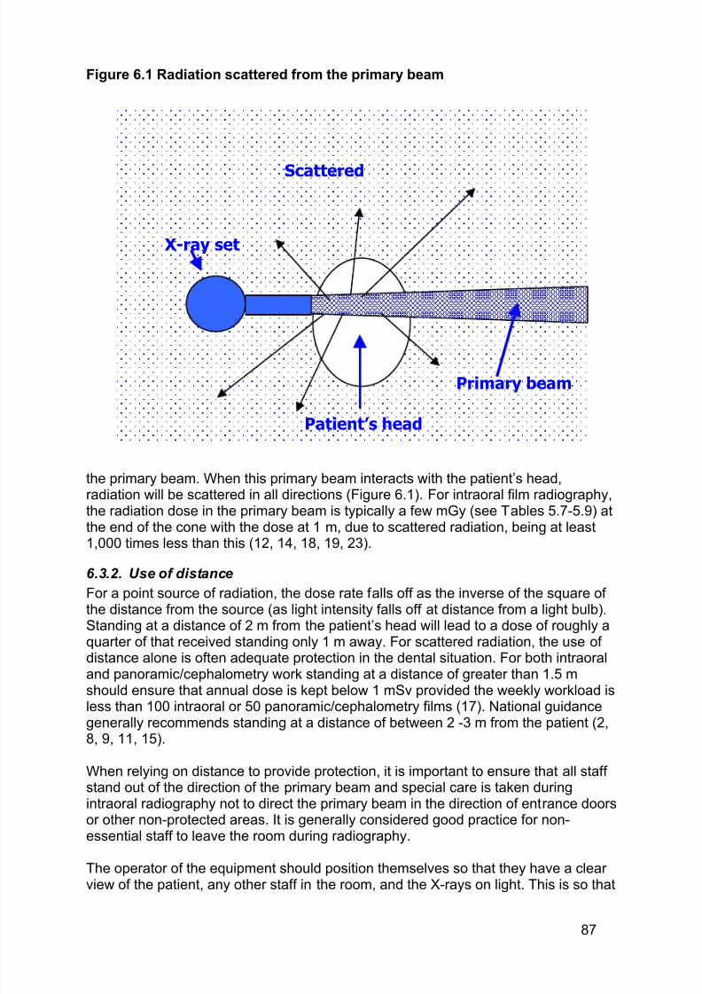
7/14/2019 136_en
http://slidepdf.com/reader/full/136en 91/120
87
Figure 6.1 Radiation scattered from the primary beam
the primary beam. When this primary beam interacts with the patient’s head,radiation will be scattered in all directions (Figure 6.1). For intraoral film radiography,the radiation dose in the primary beam is typically a few mGy (see Tables 5.7-5.9) at
the end of the cone with the dose at 1 m, due to scattered radiation, being at least1,000 times less than this (12, 14, 18, 19, 23).
6.3.2. Use of distance
For a point source of radiation, the dose rate falls off as the inverse of the square of the distance from the source (as light intensity falls off at distance from a light bulb).Standing at a distance of 2 m from the patient’s head will lead to a dose of roughly aquarter of that received standing only 1 m away. For scattered radiation, the use of distance alone is often adequate protection in the dental situation. For both intraoraland panoramic/cephalometry work standing at a distance of greater than 1.5 m
should ensure that annual dose is kept below 1 mSv provided the weekly workload isless than 100 intraoral or 50 panoramic/cephalometry films (17). National guidancegenerally recommends standing at a distance of between 2 -3 m from the patient (2,8, 9, 11, 15).
When relying on distance to provide protection, it is important to ensure that all staff stand out of the direction of the primary beam and special care is taken duringintraoral radiography not to direct the primary beam in the direction of entrance doorsor other non-protected areas. It is generally considered good practice for non-essential staff to leave the room during radiography.
The operator of the equipment should position themselves so that they have a clear view of the patient, any other staff in the room, and the X-rays on light. This is so that
Primary beam
Scattered
X-ray set
Patient’s head
7/14/2019 136_en
http://slidepdf.com/reader/full/136en 92/120
88
they can assess that all are correctly positioned at exposure initiation and that theexposure terminates correctly.
6.3.3. Use of protective screens etc
For low workload situations (i.e. less than the workload in Section 6.3.2 above) extraprotection for staff is not usually required provided that the room is large enough to
allow staff to stand some 2 m away from the patient (17). However, for highradiographic workload or very cramped location, extra protection can be provided,either in the form of protective panels for staff to stand behind or as protective apronsfor staff to wear. If such protection is required it is recommended that the advice of a‘qualified expert’ be sought.
6.3.4. Classification of areas
Article 18 of the BSS requires the designation of controlled areas, defined as an areasubject to special rules to ensure staff safety. For hospital radiography it is normal for the whole X-ray room to be designated as controlled. However, for the low workloaddental situation, UK guidance (17) has taken a pragmatic view of this requirement
and advises that the controlled area be defined as the area around the X-rayequipment that staff should vacate during exposure. Consequently, in the UK it isrecommended that for panoramic (no more than 50 exposures taken per week) andintraoral units (no more than 100 exposures taken per week) the controlled area isdefined during X-ray exposure as: within 1.5 m of the X-ray tube and patient andwithin the primary X-ray beam until sufficiently attenuated by distance or shielding,(illustrated in Figure 6.2 - for the intraoral unit). Staff should ensure that they are wellout of this area, i.e. some 2-3 m away or out of the room, during radiography.However, it is emphasised that the advice of a ‘qualified expert’ should be sought indefining controlled areas. Such advice is essential for higher workload situations or for cephalometry units.
Recommendation 6 C
6.3.5. Holding patients
Exceptionally, it might be necessary to provide assistance by supporting ahandicapped patient or child. If patient assistance is required, the assisting adultshould be provided with a lead apron and positioned so that all parts of their body areout of the main beam. If this is a regular requirement within a practice, then theadvice of a qualified expert should be sought as to the best methods of protection for the assistant and the need for personal monitoring.
The dental film or detector should only be held by the patient when it cannototherwise be kept in position. It should never be hand held by a member of the dentalpractice staff. If it is necessary for someone other than the patient to hold the film,
Maintaining adequate distance is normally the only measure required to ensure
staff dose is ALARA. This can be achieved by defining an area that staff do not
normally enter during X-ray exposure.
ED NR
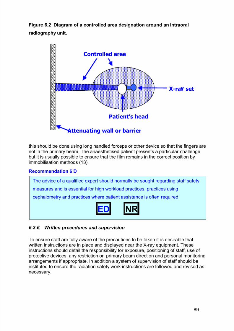
7/14/2019 136_en
http://slidepdf.com/reader/full/136en 93/120
89
Figure 6.2 Diagram of a controlled area designation around an intraoral
radiography unit.
this should be done using long handled forceps or other device so that the fingers arenot in the primary beam. The anaesthetised patient presents a particular challengebut it is usually possible to ensure that the film remains in the correct position byimmobilisation methods (13).
Recommendation 6 D
6.3.6. Written procedures and supervision
To ensure staff are fully aware of the precautions to be taken it is desirable thatwritten instructions are in place and displayed near the X-ray equipment. Theseinstructions should detail the responsibility for exposure, positioning of staff, use of protective devices, any restriction on primary beam direction and personal monitoringarrangements if appropriate. In addition a system of supervision of staff should beinstituted to ensure the radiation safety work instructions are followed and revised asnecessary.
The advice of a qualified expert should normally be sought regarding staff safety
measures and is essential for high workload practices, practices using
cephalometry and practices where patient assistance is often required.
ED NR
Attenuating wall or barrier
Controlled area
Patient’s head
X-ra set
7/14/2019 136_en
http://slidepdf.com/reader/full/136en 94/120
90
Recommendation 6 E
6.4. Design of the facility
6.4.1. Protection for adjacent areas
In deciding where to install dental X-ray equipment, it is essential to consider thelikely consequences in terms of radiation dose to staff and members of the public inadjacent areas. This is particularly important if equipment is located close to apartition wall (i.e. within 1.5m for low workload situations), for any walls or floor in thedirection of the primary beam (intraoral and cephalometry) and for high workload use.Ideally, the advice of a qualified expert should be sought to establish the requiredwall and floor structural attenuation.
Protection is often quoted in terms of the thickness of lead (usually some 0.1-1mm)required and this will be dependent on such factors as distance of the barrier fromthe X-ray tube, the use of adjacent area, workload etc (10, 11, 19). To achieve suchlevels of protection, it is usually sufficient to ensure that walls and floors are of solidconstruction, e.g. concrete blockwork or brick construction. Alternatively lead linedplywood or plasterboard can be used to obtain the desired protection. For theaverage dental facility, structural protection can readily be achieved using traditional
building materials.
It is possible that the dental supplier installing the equipment will be able to providethe advice of a qualified expert to assist with installation design and commissioningchecks.
6.4.2. Room layout
Consideration needs to be given to the layout of the room so that radiation safety isoptimised. The room should be of adequate size to allow all staff who need to remainwithin the room to position themselves outside the controlled area during exposure. As described in 6.3.2 above, it is essential that the operator of the equipment can
position themselves so that they have a view of: patient, controlled area and ‘X-rayson’ indicator light. If the room size is limited, it might be necessary for staff to positionthemselves outside the room, in which case a mirror might be required to ensure thata clear view of the room is maintained.
The equipment should be positioned so that the controlled area does not extend toany entrances and so that the primary beam will not be directed towards anydoorways or ground floor windows.
The exposure switch should be located so that that the operator can either remainoutside of the controlled area or be behind a protective screen. In addition, attention
should be given to the location of the mains on switch. This should be placed so that,in the unlikely event of failure to terminate exposure, the unit can be readily
All practices should have written instructions for staff radiation safety.
ED
7/14/2019 136_en
http://slidepdf.com/reader/full/136en 95/120
91
disconnected from the mains supply without members of staff being exposed toprimary radiation.
6.4.3. Signs and warning lights
It is important to ensure that unauthorised access into the controlled area is limitedduring X-ray exposure. This may be achieved by supervision by the operator backed
up by the use of warning signs and lights. The requirement for warning signs andlights varies from country to country within the EU. It is a common requirement thatall doors leading into a room where dental X-ray equipment is used should have asign that indicates the presence of the X-ray equipment. However, such permanentsigns have little value if the room is used for other activities apart from X-ray work aspractice staff quickly learn to ignore them.
A pragmatic approach to this is given in the UK guidance (16). Provided thecontrolled area does not extend to an entrance, then access to the area can becontrolled by the operator of the equipment and no warning lights or signs arenecessary. However, if the controlled area does extend to an entrance, then an
automatic warning light should be provided to indicate that radiography is inprogress. This light should be illuminated when the mains supply is on, and themains supply should be kept switched off unless radiography is imminent. A warningnotice should also be provided explaining the significance of the light. Such awarning may be unnecessary if the operator is always able to stand in the doorway toprevent access whilst radiography is underway.
Recommendation 6F
6.5 Training staff
All staff in a dental practice (not just the equipment operator) must be aware of therisks associated with the use of X-ray equipment, the precautions required to keep
their dose ALARA and the importance of complying with these arrangements (4).Many dental employees will receive some radiation awareness training as part of their professional training. It is, however, essential that local arrangements beexplained to all staff. For members of staff who have not received any radiationsafety training (e.g. some dental nurses) then it is important that arrangements bemade (by either attending suitable training courses or the provision of adequate in-house training) to ensure that they have adequate training.
It is essential that consideration be given to the layout and structural protection of
any dental X-ray facility. A qualified expert should be consulted when planning new
facilities or making significant changes.
ED NR
7/14/2019 136_en
http://slidepdf.com/reader/full/136en 96/120
92
Recommendation 6 G
6.6 Dealing with incidents
It is very rare in dental practice for incidents to occur that lead to staff receivingsignificant dose levels. However, exposure to the primary beam, especially if the unitfails to terminate correctly, can be such a cause and would require investigation. It isimportant that the investigation be carried out promptly, whilst the details of theincident are still fresh in people’s memories. A qualified expert should normally be
consulted to aid in estimation of dose levels received. Any incidents should bereported to the competent authorities in line with local legal requirements.
6.7 References
1. 1998. Advice on exposure to ionising radiation during pregnancy. Joint guidance from NRPB/CoR/RCR.2. 1996. Code of practice for radiological protection in dentistry. Radiological Protection Institute of Ireland.3. 1996. Council Directive 96/29/Euratom of 13 May 1996 laying down basic safety standards for the protection of the
health workers and the general public against the dangers arising from ionizing radiation.4. 2000. EU Guidelines on Education and Training in Radiation Protection for Medical Exposures. Radiation Protection
116.5. 1990. ICRP Publication 60. Recommendations of the International Commission on Radiatiological Protection. Annal of
the ICRP 21.6. 1990. Implementation of the principle of as low as reasonably achievable (ALARA) for medical and dental personnel
Report Number 107. NRCP.7. 1993. Radiation Exposure of the UK population - Review NRPB R263.8. 2000. Radiation protection in dentistry recommended safety procedures for the use of dental x-rayequipment safety
code 30. Enviromental Health Directorate, Canada.9. 1989. Recommendations on radiographic procedures. Revision of Federation Dentaire Internationale technical report
No. 8. International Dental Journal 39:147-8.10. 1999. Use and regulatory control of dental x-ray installations ST3.1. Radiation and Nuclaer Safety Authority, Finland.11. A. D. A. Council on Scientific Affairs. 2001. An update on radiographic practices: information and
recommendations.ADA Council on Scientific Affairs. Journal of the American Dental Association 132:234-8.12. de Haan, R. A., and J. van Aken. 1990. Effective dose equivalent to the operator in intra-oral dental radiography.
Dento-Maxillo-Facial Radiology 19:113-8.13. Diner, M. H., P. Marcoux, and V. Legault. 1990. Intraoral radiographic techniques for the anaesthetized patient.
Journal of the International Association of Dentistry for Children 20:17-21.14. Hirschmann, P. N. 1987. The current status of panoramic radiography. International Dental Journal 37:31-7.15. Matarasso, S., F. Coraggio, R. Martuscelli, and F. D'Antonio. 1990. [Radiologic risk and INAIL insurance].
Stomatologia Mediterranea 10:207-12.16. Monsour, P. A., B. J. Kruger, A. Barnes, and A. Sainsbury. 1988. Measures taken to reduce X-ray exposure of the
patient, operator, and staff. Australian Dental Journal 33:181-92.17. National Radiological Protection Board. 2001. Guidance notes for dental practitioners on the safe use of x-ray
equipment. NRPB dental x-ray protection services.18. Reid, J. A., J. C. MacDonald, T. A. Dekker, and B. U. Kuppers. 1993. Radiation exposures around a panoramic
dental x-ray unit. Oral Surgery, Oral Medicine, Oral Pathology 75:780-2.19. Sutton, and Williams. 2000. Radiation Shielding for diagnostic X-rays BIR.20. Wagner , and Archer. 1998. Minimizing risks from fluoroscopic x-rays, Partners in Radiation Management.21. Warin, A. P. 1979. Radiodermatitis of the hands in a dental practitioner. Clinical & Experimental Dermatology 4:129-
32.22. Wasylko, L., D. Matsui, S. M. Dykxhoorn, M. J. Rieder, and S. Weinberg. 1998. A review of common dental
treatments during pregnancy: implications for patients and dental personnel. Journal/Canadian Dental Association.Journal de l Association Dentaire Canadienne 64:434-9.
23. Watkins, A. J. 2002. Presented at the IPEM Annual Scientific Meeting.
Dental practice employees should receive training in radiation protection so that
they understand the risks involved and the precautions to be taken.
ED NR

7/14/2019 136_en
http://slidepdf.com/reader/full/136en 97/120
93
Appendix 1 Methodology
1.1. Aim
To develop evidence based guidelines on radiation protection in dental
radiology
1.2. Establishment of guideline development team and the scope of the guidelines
One of the first steps in production of evidence based guidelines is toestablish a guidelines development panel. A multidisciplinary team wasestablished for the production of the guidelines on radiation protection indentistry (refer to Panel, page 8). A meeting of the team was convened(February 2002) and the scope and content of the guidelines was discussedand refined.
The consensus was that our target population for the guidelines was dentistsworking in general practice. We identified ten key topic areas that needed tobe covered to produce a comprehensive guideline:
· Dose and risk· Referral criteria· Consent· Diagnostic Reference Levels (DRLs)· Previous radiographs and reports
· Techniques, equipment and dose limitation· Quality standards· Quality assurance· Equipment acceptance tests· Staff protection
Members of the guideline development team were divided into sub-groupsand assigned to topic areas on the basis of personal expertise and skills. Itwas recognised that there would be some overlap between certain topics. Weattempted to ensure that any of the overlapping topics had at least onemember of the team working on both sub-groups.
Each sub-group was responsible for outlining relevant issues to be coveredwithin their topic area, the screening and data extraction of relevant identifiedpapers, the grading of the scientific content of these papers and the report of the findings.
The overall administration of the guidelines was undertaken by a ProjectCoordinator based in Manchester, UK.
7/14/2019 136_en
http://slidepdf.com/reader/full/136en 98/120
94
1.3. Identification of the literature
We undertook an initial search for existing guidelines within the area of radiation protection. We searched the FDI guideline database(www.fdiworldental.org), the National Guidelines Clearing House
(www.guidelines.gov/index.asp) and Medline. A list of identified guidelineliterature was circulated to all members of the development team for screening. Any guideline identified by one or more members of the team asbeing potentially relevant was obtained and distributed to the whole team.
We also performed searches for papers on the ten identified topic areas. Thedevelopment of the search strategies for each topic was an iterative process. An initial ‘scoping’ search was undertaken. The aim of these scopingsearches was to gain an overview of the volume of literature; identify further questions that may need to be addressed; establish the researchmethodologies used within each area and identify further search terms for
refining the search strategy.
A set of key terms (controlled vocabulary (e.g MeSH) and free text words)was used as the basis for all the sub-group scoping searches (Box 1), withadditional subject specific search terms added as appropriate.
Box 1.
MeSH and free text terms used (MEDLINE via OVID BIOMED)
1 exp Radiography/2 radiograph$.mp.3 radiation.mp.4 exp Radiology/5 radiol$.mp.6 exp X-Rays/ or x-ray.mp. (80927)7 xra$.mp.8 (dental or dentistry).mp.9 exp Dentistry/10 (intra-oral or intraoral).mp.11 cephalometr$.mp.
12 orthopantom$.mp.13 panoramic.mp.14 (bite-wing or bitewing).mp.15 MANDIBLE/ or mandible.mp.16 MAXILLA/ or maxilla.mp.17 or/1-718 or/8-16
The results of the searches were imported into Endnote 5.0 and codedaccordingly. We distributed the results for each individual scoping search to
the appropriate topic-group where the titles and abstracts were reviewed.Members of the topic-groups were asked to comment on the sensitivity and
7/14/2019 136_en
http://slidepdf.com/reader/full/136en 99/120
95
specificity of the search results. Where the scoping searches did not appear to identify relevant articles, or the search results identified to many non-relevant articles, the search strategies were refined following discussion (viaemail) with the team members. This process often took several rounds of discussion and refinement before we established sensitive search strategies.
We searched MEDLINE (OVID BIOMED) for each topic back to 1966 exceptfor the Dose & Risk topic group. With regard to Dose & Risk, it was felt thatthe International Commission on Radiation Protection report 60 (2), whichchanged the methodology of risk calculation in relation to radiation exposure,acted as an appropriate starting point. Previous calculations of risk would notbe comparable. In addition the benchmark review paper by White (3)recalculated pre1990 dose/risk papers using ICRP 60 methods (2), thereforefor this topic group, searching commenced at 1990.
We undertook additional citation searches of key authors/papers and
searches of websites of National/International professional bodies. Theexpertise of the project team was exploited to identify both unpublished andongoing studies. Non-English language articles were included wheretranslations were available.
1.4. Assessment of relevance
Each sub-group was responsible for the screening of titles and abstractsidentified through the electronic searching. The process was carried outindependently by sub-group team members. The details of those recordsdeemed potentially relevant to the subject area by at one or more members of the sub-group were passed back to the Project Coordinator for collection of the full article.
During this process, members of the sub-groups were asked to ‘flag-up’ anyrecords identified in their search results that might be of relevance to the other topic areas of interest.
1.4.1. Data extraction
All studies obtained through the searching were distributed to all members of
the relevant sub-group. The papers were reviewed and data extractedindependently. The data extracted was used to form evidence tables,providing details of the study design, aims, methods, results and conclusions.Due to the wide variation in study designs utilised in this area, a single validityassessment form was not used, however the strengths and weaknesses of each study were noted and an attempt to grade the paper on its scientificmerit was performed.
1.4.2. Data synthesis and grading of recommendations
Draft guidelines, based on the information produced in the evidence tables,
was then drawn up by each sub-group. These were circulated to all membersof the guideline development team, along with tables, prior to a final meeting
7/14/2019 136_en
http://slidepdf.com/reader/full/136en 100/120
96
(October 2002). The group discussed the evidence giving consideration to thevolume, consistency and generalisablity of the findings.Recommendations were produced, based on the available evidence andgraded using an adaptation of the SIGN grading system to reflect the studytypes utilised in this area of research (1). Where European Directives exist,
these were noted. (Refer to Table 1.1, Chapter 1.)
1.5 References
1. May 2002. Scottish Intercollegiate Guidelines Network (SIGN). A guideline developers' handbook. ReportNo.: SIGN 50.
2. International Commission on Radiological Protection. 1991. ICRP Publication 60. Recommendationsof the International Commission on Radiological Protection. Annals of the International Commission onRadiological protection Vol. 21, No 1-3. Pergamon, Oxford, UK.
3. White, S. C. 1992. Assessment of radiation risk from dental radiography. Dentomaxillofac Radiol 21:118-26.
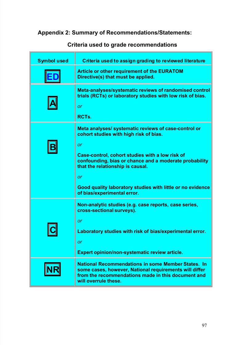
7/14/2019 136_en
http://slidepdf.com/reader/full/136en 101/120
97
Appendix 2: Summary of Recommendations/Statements:
Criteria used to grade recommendations
Symbol used Criteria used to assign grading to reviewed literature
EDArticle or other requirement of the EURATOMDirective(s) that must be applied.
A
Meta-analyses/systematic reviews of randomised controltrials (RCTs) or laboratory studies with low risk of bias.
or
RCTs.
B
Meta analyses/ systematic reviews of case-control or cohort studies with high risk of bias.
or
Case-control, cohort studies with a low risk of confounding, bias or chance and a moderate probabilitythat the relationship is causal.
or
Good quality laboratory studies with little or no evidenceof bias/experimental error.
C
Non-analytic studies (e.g. case reports, case series,cross-sectional surveys).
or
Laboratory studies with risk of bias/experimental error.
or
Expert opinion/non-systematic review article.
NRNational Recommendations in some Member States. Insome cases, however, National requirements will differ from the recommendations made in this document andwill overrule these.
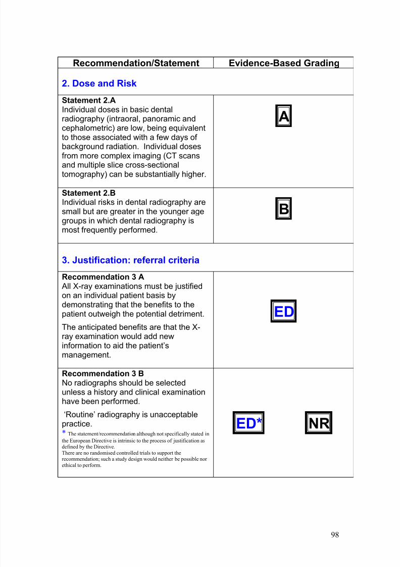
7/14/2019 136_en
http://slidepdf.com/reader/full/136en 102/120
98
Recommendation/Statement Evidence-Based Grading
2. Dose and Risk
Statement 2.AIndividual doses in basic dentalradiography (intraoral, panoramic andcephalometric) are low, being equivalentto those associated with a few days of background radiation. Individual dosesfrom more complex imaging (CT scansand multiple slice cross-sectionaltomography) can be substantially higher.
A
Statement 2.BIndividual risks in dental radiography aresmall but are greater in the younger agegroups in which dental radiography ismost frequently performed.
B
3. Justification: referral criteria
Recommendation 3 A All X-ray examinations must be justified
on an individual patient basis bydemonstrating that the benefits to thepatient outweigh the potential detriment.
The anticipated benefits are that the X-ray examination would add newinformation to aid the patient’smanagement.
ED
Recommendation 3 BNo radiographs should be selectedunless a history and clinical examinationhave been performed.
‘Routine’ radiography is unacceptablepractice.* The statement/recommendation although not specifically stated in
the European Directive is intrinsic to the process of justification asdefined by the Directive.
There are no randomised controlled trials to support therecommendation; such a study design would neither be possible nor
ethical to perform.
ED* NR
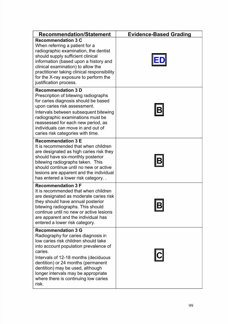
7/14/2019 136_en
http://slidepdf.com/reader/full/136en 103/120
99
Recommendation/Statement Evidence-Based GradingRecommendation 3 CWhen referring a patient for aradiographic examination, the dentist
should supply sufficient clinicalinformation (based upon a history andclinical examination) to allow thepractitioner taking clinical responsibilityfor the X-ray exposure to perform the justification process.
ED
Recommendation 3 DPrescription of bitewing radiographsfor caries diagnosis should be basedupon caries risk assessment.
Intervals between subsequent bitewingradiographic examinations must bereassessed for each new period, asindividuals can move in and out of caries risk categories with time.
B
Recommendation 3 EIt is recommended that when childrenare designated as high caries risk theyshould have six-monthly posterior bitewing radiographs taken. Thisshould continue until no new or activelesions are apparent and the individualhas entered a lower risk category. .
B
Recommendation 3 FIt is recommended that when childrenare designated as moderate caries riskthey should have annual posterior bitewing radiographs. This shouldcontinue until no new or active lesionsare apparent and the individual hasentered a lower risk category.
B
Recommendation 3 GRadiography for caries diagnosis inlow caries risk children should takeinto account population prevalence of caries.
Intervals of 12-18 months (deciduousdentition) or 24 months (permanentdentition) may be used, althoughlonger intervals may be appropriatewhere there is continuing low caries
risk.
C
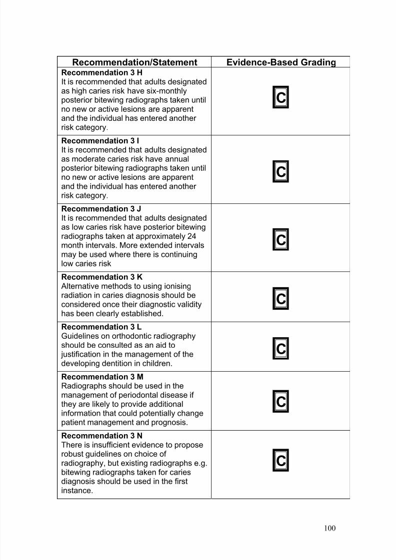
7/14/2019 136_en
http://slidepdf.com/reader/full/136en 104/120
100
Recommendation/Statement Evidence-Based GradingRecommendation 3 HIt is recommended that adults designatedas high caries risk have six-monthly
posterior bitewing radiographs taken untilno new or active lesions are apparentand the individual has entered another risk category.
C
Recommendation 3 IIt is recommended that adults designatedas moderate caries risk have annualposterior bitewing radiographs taken untilno new or active lesions are apparentand the individual has entered another
risk category.
C
Recommendation 3 JIt is recommended that adults designatedas low caries risk have posterior bitewingradiographs taken at approximately 24month intervals. More extended intervalsmay be used where there is continuinglow caries risk
C
Recommendation 3 K Alternative methods to using ionising
radiation in caries diagnosis should beconsidered once their diagnostic validityhas been clearly established.
C
Recommendation 3 LGuidelines on orthodontic radiographyshould be consulted as an aid to justification in the management of thedeveloping dentition in children.
C
Recommendation 3 MRadiographs should be used in the
management of periodontal disease if they are likely to provide additionalinformation that could potentially changepatient management and prognosis.
C
Recommendation 3 NThere is insufficient evidence to proposerobust guidelines on choice of radiography, but existing radiographs e.g.bitewing radiographs taken for cariesdiagnosis should be used in the first
instance.
C
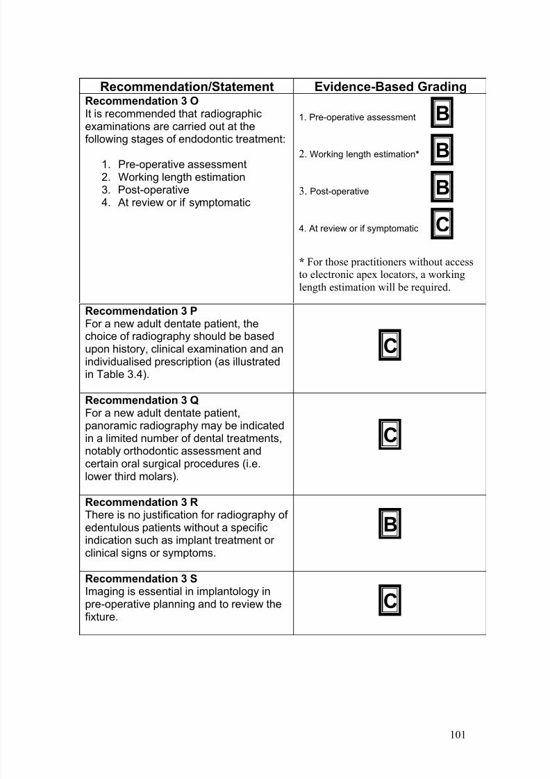
7/14/2019 136_en
http://slidepdf.com/reader/full/136en 105/120
101
Recommendation/Statement Evidence-Based GradingRecommendation 3 OIt is recommended that radiographicexaminations are carried out at the
following stages of endodontic treatment:
1. Pre-operative assessment2. Working length estimation3. Post-operative4. At review or if symptomatic
1. Pre-operative assessment B
2. Working length estimation* B
3. Post-operative B
4. At review or if symptomatic C
* For those practitioners without access
to electronic apex locators, a workinglength estimation will be required.
Recommendation 3 PFor a new adult dentate patient, thechoice of radiography should be basedupon history, clinical examination and anindividualised prescription (as illustratedin Table 3.4).
C
Recommendation 3 Q
For a new adult dentate patient,panoramic radiography may be indicatedin a limited number of dental treatments,notably orthodontic assessment andcertain oral surgical procedures (i.e.lower third molars).
C
Recommendation 3 RThere is no justification for radiography of edentulous patients without a specific
indication such as implant treatment or clinical signs or symptoms.
B
Recommendation 3 SImaging is essential in implantology inpre-operative planning and to review thefixture.
C
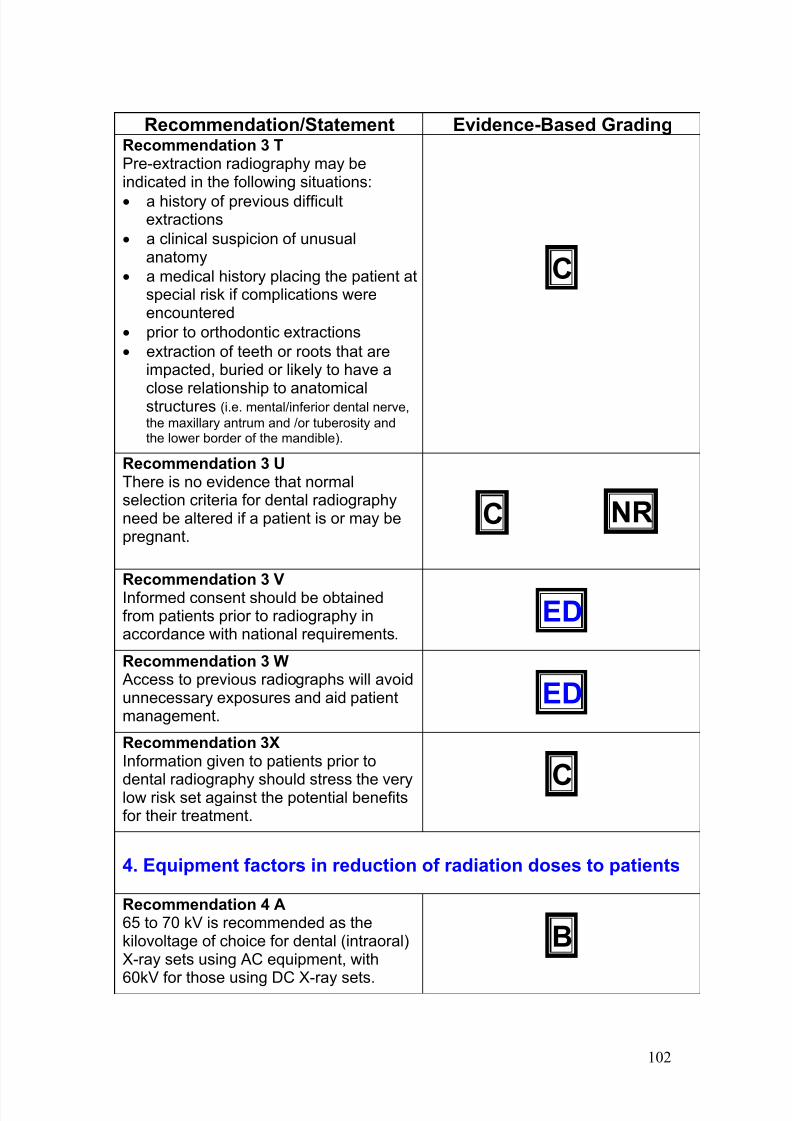
7/14/2019 136_en
http://slidepdf.com/reader/full/136en 106/120
102
Recommendation/Statement Evidence-Based GradingRecommendation 3 TPre-extraction radiography may beindicated in the following situations:
· a history of previous difficultextractions
· a clinical suspicion of unusualanatomy
· a medical history placing the patient atspecial risk if complications wereencountered
· prior to orthodontic extractions
· extraction of teeth or roots that areimpacted, buried or likely to have a
close relationship to anatomicalstructures (i.e. mental/inferior dental nerve,
the maxillary antrum and /or tuberosity andthe lower border of the mandible).
C
Recommendation 3 UThere is no evidence that normalselection criteria for dental radiographyneed be altered if a patient is or may bepregnant.
C NR
Recommendation 3 VInformed consent should be obtainedfrom patients prior to radiography inaccordance with national requirements.
ED
Recommendation 3 W Access to previous radiographs will avoidunnecessary exposures and aid patientmanagement.
ED
Recommendation 3XInformation given to patients prior to
dental radiography should stress the verylow risk set against the potential benefitsfor their treatment.
C
4. Equipment factors in reduction of radiation doses to patients
Recommendation 4 A65 to 70 kV is recommended as thekilovoltage of choice for dental (intraoral)X-ray sets using AC equipment, with
60kV for those using DC X-ray sets.
B
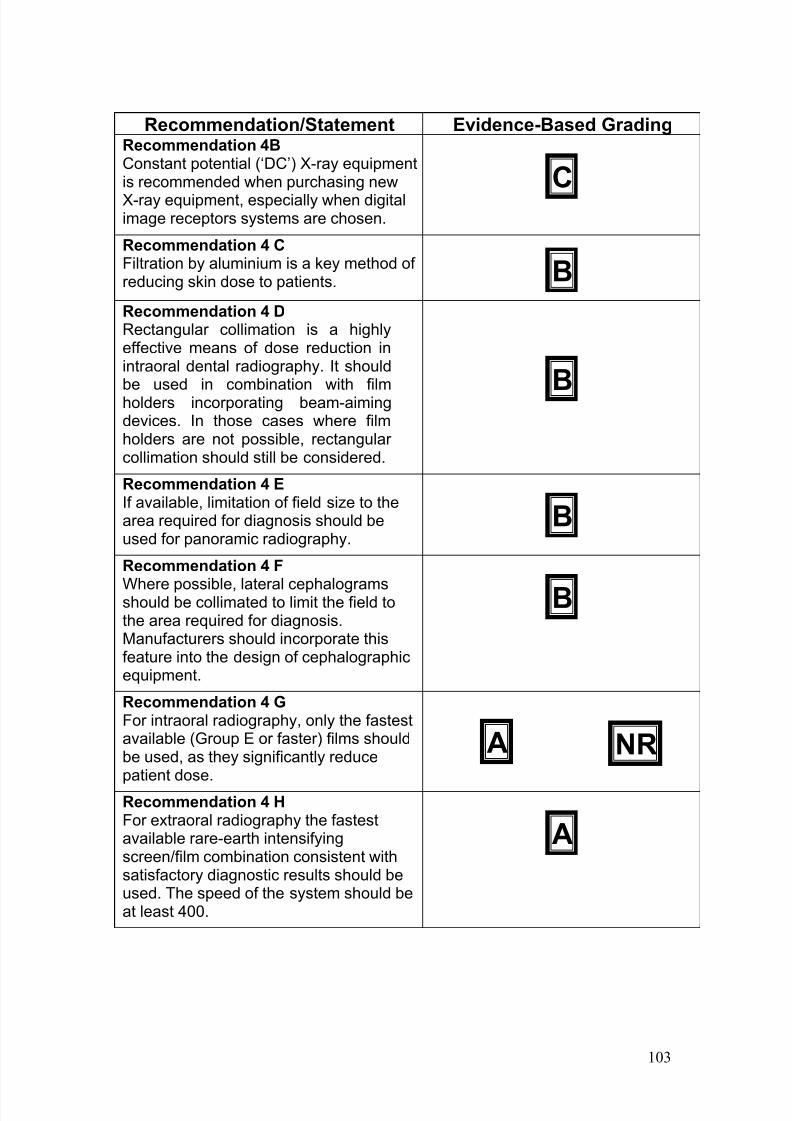
7/14/2019 136_en
http://slidepdf.com/reader/full/136en 107/120
103
Recommendation/Statement Evidence-Based GradingRecommendation 4BConstant potential (‘DC’) X-ray equipmentis recommended when purchasing new
X-ray equipment, especially when digitalimage receptors systems are chosen.
C
Recommendation 4 CFiltration by aluminium is a key method of reducing skin dose to patients. B
Recommendation 4 DRectangular collimation is a highlyeffective means of dose reduction inintraoral dental radiography. It should
be used in combination with filmholders incorporating beam-aimingdevices. In those cases where filmholders are not possible, rectangular collimation should still be considered.
B
Recommendation 4 EIf available, limitation of field size to thearea required for diagnosis should beused for panoramic radiography.
B
Recommendation 4 F
Where possible, lateral cephalogramsshould be collimated to limit the field tothe area required for diagnosis.Manufacturers should incorporate thisfeature into the design of cephalographicequipment.
B
Recommendation 4 GFor intraoral radiography, only the fastestavailable (Group E or faster) films shouldbe used, as they significantly reducepatient dose.
A NR
Recommendation 4 HFor extraoral radiography the fastestavailable rare-earth intensifyingscreen/film combination consistent withsatisfactory diagnostic results should beused. The speed of the system should beat least 400.
A
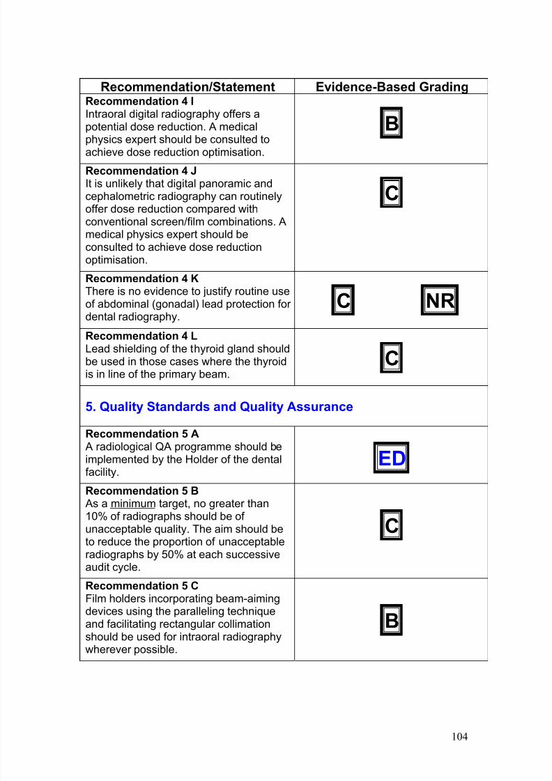
7/14/2019 136_en
http://slidepdf.com/reader/full/136en 108/120
104
Recommendation/Statement Evidence-Based GradingRecommendation 4 IIntraoral digital radiography offers apotential dose reduction. A medical
physics expert should be consulted toachieve dose reduction optimisation.
B
Recommendation 4 JIt is unlikely that digital panoramic andcephalometric radiography can routinelyoffer dose reduction compared withconventional screen/film combinations. Amedical physics expert should beconsulted to achieve dose reductionoptimisation.
C
Recommendation 4 KThere is no evidence to justify routine useof abdominal (gonadal) lead protection for dental radiography.
C NR
Recommendation 4 LLead shielding of the thyroid gland shouldbe used in those cases where the thyroidis in line of the primary beam.
C
5. Quality Standards and Quality Assurance
Recommendation 5 A A radiological QA programme should beimplemented by the Holder of the dentalfacility.
ED
Recommendation 5 B As a minimum target, no greater than10% of radiographs should be of unacceptable quality. The aim should be
to reduce the proportion of unacceptableradiographs by 50% at each successiveaudit cycle.
C
Recommendation 5 CFilm holders incorporating beam-aimingdevices using the paralleling techniqueand facilitating rectangular collimationshould be used for intraoral radiographywherever possible.
B
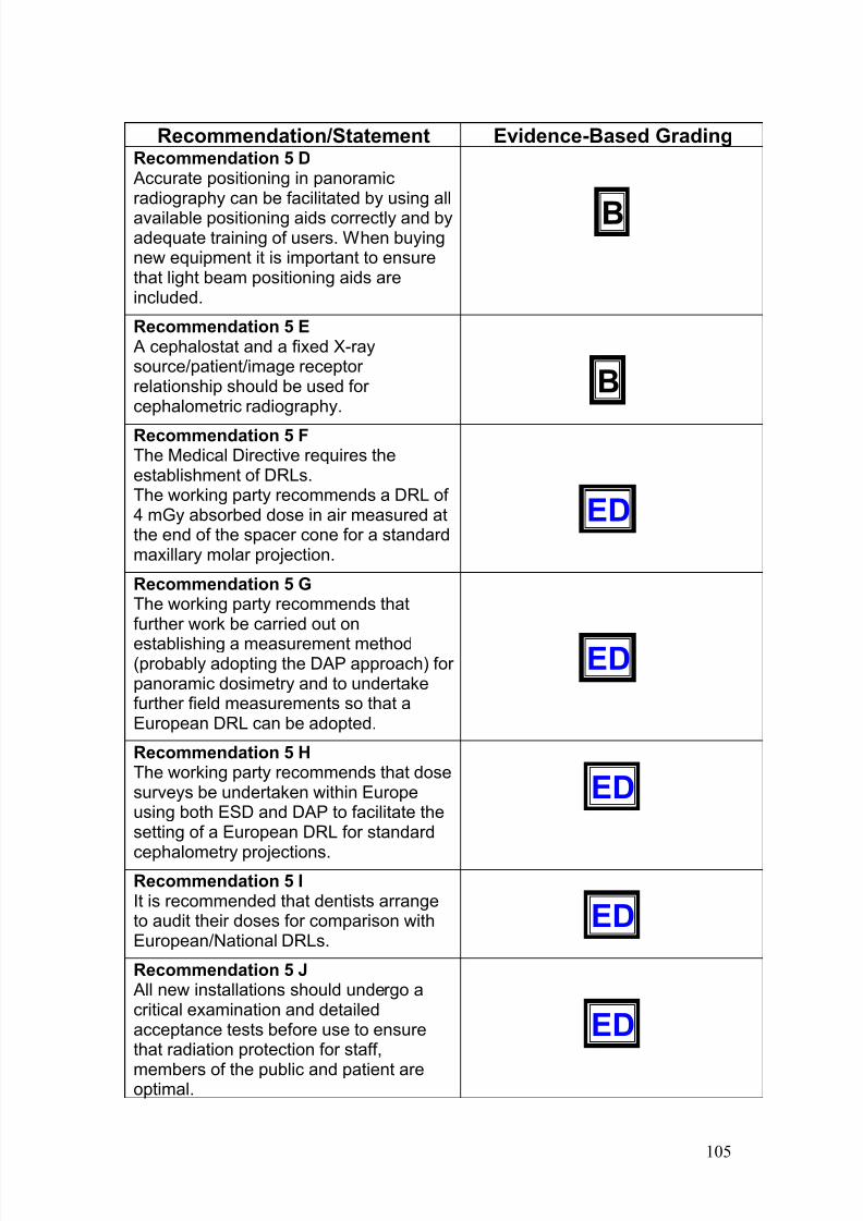
7/14/2019 136_en
http://slidepdf.com/reader/full/136en 109/120
105
Recommendation/Statement Evidence-Based GradingRecommendation 5 D Accurate positioning in panoramicradiography can be facilitated by using all
available positioning aids correctly and byadequate training of users. When buyingnew equipment it is important to ensurethat light beam positioning aids areincluded.
B
Recommendation 5 E A cephalostat and a fixed X-raysource/patient/image receptor relationship should be used for cephalometric radiography.
B
Recommendation 5 FThe Medical Directive requires theestablishment of DRLs.The working party recommends a DRL of 4 mGy absorbed dose in air measured atthe end of the spacer cone for a standardmaxillary molar projection.
ED
Recommendation 5 GThe working party recommends thatfurther work be carried out on
establishing a measurement method(probably adopting the DAP approach) for panoramic dosimetry and to undertakefurther field measurements so that aEuropean DRL can be adopted.
ED
Recommendation 5 HThe working party recommends that dosesurveys be undertaken within Europeusing both ESD and DAP to facilitate thesetting of a European DRL for standard
cephalometry projections.
ED
Recommendation 5 IIt is recommended that dentists arrangeto audit their doses for comparison withEuropean/National DRLs.
ED
Recommendation 5 J All new installations should undergo acritical examination and detailedacceptance tests before use to ensurethat radiation protection for staff,
members of the public and patient areoptimal.
ED
7/14/2019 136_en
http://slidepdf.com/reader/full/136en 110/120
106
Recommendation/Statement Evidence-Based GradingRecommendation 5 K All dental X-ray equipment shouldundergo regular routine tests to ensure
that radiation protection, for both practiceusers and patients, has not significantlydeteriorated.
ED NR
Recommendation 5 L
A QA system for monitoring darkroomand processing conditions should beinstituted in each dental facility. As aminimum:
· The temperature of the developer should be checked prior to film
processing and the developmenttime adjusted in accordance.
· For automatic processing, theprocessor should be properlycleaned and maintained.
Processing solutions should be changedat regular intervals as indicated by routinemonitoring tests.
B
Recommendation 5 M All those involved in radiography shouldhave received adequate theoretical and
practical training for the purpose of radiological practices and relevantcompetence in radiation protection.Continuing education and training after qualification is required, particularly whennew equipment or techniques areadopted.
ED
Recommendation 5 NThe person responsible for the QA
programme should make an audit of theprogramme at intervals not exceeding 12months.
C
7/14/2019 136_en
http://slidepdf.com/reader/full/136en 111/120
107
Recommendation/Statement Evidence-Based Grading
6. Staff protection
Recommendation 6 AThe lead dental practitioner should ensurethat the arrangements for staff protectionare assessed and implemented in line withthe requirements of the country legislationand in consultation with appropriatemedical physics expert.
ED NR
Recommendation 6 BNormal dental practice should not lead tomembers of staff receiving doses above 1mSv per year provided the ALARA
principle is applied. Special precautions for pregnant staff are not normally requiredwhen it can be assured that the doseduring pregnancy is 1 mSv (which isnormally the case in dental practice).
C
Recommendation 6 CMaintaining adequate distance is normallythe only measure required to ensure staff dose is ALARA. This can be achieved bydefining an area that staff do not normallyenter during X-ray exposure.
ED NR
Recommendation 6 DThe advice of a qualified expert shouldnormally be sought regarding staff safetymeasures and is essential for highworkload practices, practices usingcephalometry and practices where patientassistance is often required.
ED NR
Recommendation 6 E All practices should have writteninstructions for staff radiation safety. ED
Recommendation 6FIt is essential that consideration be givento the layout and structural protection of any dental X-ray facility. A qualified expertshould be consulted when planning newfacilities or making significant changes.
ED NR
Recommendation 6 GDental practice employees should receivetraining in radiation protection so that theyunderstand the risks involved and the
precautions to be taken.
ED NR
7/14/2019 136_en
http://slidepdf.com/reader/full/136en 112/120
108
Appendix 3: Glossary
Absorbed dose: The quantity of energy deposited by the radiation per unitmass of tissue. The unit of absorbed dose is the Gray (Gy) and one gray isequal to 1 joule of energy deposited in 1 kg of tissue.
Additional filtration: This is a filter added to the inherent filter and placed inthe path of the main X-ray beam.
ALARA (As Low As Reasonably Achievable): This statement endorses theprinciple that (individual) doses should be as low as reasonably achievable,economic and social factors being taken into account.
Aluminium equivalent: The thickness of aluminium alloy affording the sameattenuation as the material in question.
Anode: The positive terminal of the X-ray tube.
Attenuation: Loss of energy from ionising radiation by absorption and scatter as it passes through matter.
Bisecting angle technique: A technique for intraoral periapical radiographyin which the X-ray beam is directed perpendicular to the bisected angleformed by the long axis of the tooth (teeth) to be imaged and by the film.
Bitewing radiograph: This is an intraoral radiographic view that
demonstrates the crowns of the teeth and the alveolar crestal bone of thepremolar and molar regions of both the maxilla and mandible.
Case-control study: This is a study that identifies patients with an outcomeof interest (i.e. cases) and control patients without the same outcome andretrospectively assessing if they had the exposure of interest.
Case series: A report on a series of patients with an outcome of interest inwhich no control group was involved.
Cephalometric radiography: A method whereby reproducible lateral and
postero-anterior views of the skull are obtained by standardising head positionusing a cephalostat. Synonyms: Cephalometry; teleradiography.
Cephalostat: A rigid device to localise the patient's head in a standardisedway.
Cohort study: Two groups of patients (cohorts) are chosen, one that hasreceived an exposure of interest and one that has not. Both are followed toderive the outcome of interest.
'Coin' test: A method to test the safelight(s) in the dark room. An object e.g.
a coin or key is placed on a piece of unexposed screen film or an unwrappeddental film with the safelight on and is left for the normal handling time of the
7/14/2019 136_en
http://slidepdf.com/reader/full/136en 113/120
109
film. Following normal processing, safelight fogging will be obvious if there is aclear area on the film where the coin protected the film from light. The sametest can be carried out with desktop automatic processors. N.B. Screen film,due to its greater light sensitivity, is predominately used for this test unlessonly dental films are used in the practice.
Collimation: A method of restricting the dimensions of the X-ray beam. Theterm 'field size trimming' is synonymous.
Collective dose: The multiple of average effective dose by the number of people within the population. The measurement is in man-sieverts.
Computed tomography (CT): An imaging procedure in which multipleprojections are reconstructed to produce tomographic images of the patient.
Contrast: Differences of density in a radiographic image
Constant potential ('direct current') X-ray generation: This equipmentproduces an X-ray beam with a higher proportion of high-energy photons andmay be accomplished by capacitor smoothing, triodes for ripple suppressionor 3-phase supplies.
Controlled area: An area subject to special rules to ensure staff safety and isthat area around the X-ray equipment that staff should vacate during anexposure.
Dose area product (DAP): The product of dose and beam area that can bemeasured using a large area ionisation chamber.
Cross-sectional survey: The observation of a defined population at a singlepoint in time or interval of time in which exposure and outcome aredetermined simultaneously.
Dental panoramic tomography: This is a technique that produces an imageof both jaws and their respective dentitions on a single extra-oral film. The filmis known as a panoramic radiograph.
Deterministic effects: Effects from ionising radiation in which there is athreshold below which no effect occurs and severity of the effect varies withthe dose received.
Diagnostic Reference Levels (DRLs): This measurement represents areference dose level as part of an optimisation process. They are based uponentrance dose surveys.
Digital radiography: A method of presentation of the image in a digital rather than an analog form.
7/14/2019 136_en
http://slidepdf.com/reader/full/136en 114/120
110
Dose limits: Dose limits (i.e. effective or equivalent dose) for workers andmembers of the public are specified in order to minimise detriment fromionising radiation.Specifically, dose limits are defined in the European Basic Safety Standardsas the maximum references for the doses resulting from the exposure
workers, apprentices and students and members of the public to ionisingradiation that apply to the sum of the relevant doses from external exposuresin the specified period and the 50-year committed doses (up to age 70 for children) from intakes in the same period.
Dosemeter: A dose-measuring device. See also film badge andthermoluminescent dose meter (TLD).
Effective dose: Effective dose is derived from the absorbed doses in specifictissues, the relative effect of the type and energy of radiation encountered,and the relative radiation sensitivity for the stochastic health detriments
associated with the specific tissues. It is an indicator of the increase inprobability for stochastic effects later in life for a population exposed to thegiven levels. (ICRP Publication 85. Avoidance of radiation injurie from medical interventional procedures. Ann
ICRP 2000, 30(2) Pergamon. Elsevier Science Ltd, Oxford, UK)This is an indicator for theprobability of occurrence of stochastic effect and is the sum of the weightedequivalent doses in all of the tissues and organs of the body affected byionising radiation. Thus the multiplicity of the individual doses received areexpressed as a single value representing that radiation dose that would havethe same effect if it were applied uniformly to the whole body. The SI unit of measurement is the sievert (Sv).
Entrance surface dose (ESD): This is the dose measured at the surface of an irradiated structure and includes primary radiation. Backscatter from theirradiated mass may or may not be included.
Equivalent dose: This is the product of the absorbed dose multiplied by aradiation weighting factor for the nature of the incident radiation. The SI unit of measurement is the sievert (Sv).
eV: A unit to measure the energy of photons. An electron volt is the amount of energy that an electron gains as it is accelerated by a potential difference of 1
V. X-ray energies are usually measured in Kiloelecton volts.
Exposure: This is defined as the electric charge released per unit mass byionising radiation. The SI unit of measurement is coulombs per kilogram(C/kg).
Field size: The projection of the X-ray beam on a plane perpendicular to thecentral ray of X-ray beam.
Film: X-ray film consists of an emulsion sensitive to radiation and to lightcoated onto a transparent sheet of plastic. 'Direct' film is highly sensitive to X-
rays whereas 'screen film' depends upon light absorption, the spectralabsorption of which is identically matched to screen emission.
7/14/2019 136_en
http://slidepdf.com/reader/full/136en 115/120
111
Film badge: A small device consisting of holder containing a variety of filtersof differing thicknesses and a double-emulsion film to monitor and determinethe energy and type of radiation received.
Film holder: This is the generic term applied to film holding instruments andfilm holding beam alignment instruments. A film holding instrument localisesthe film intraorally whereas a film holding/beam alignment device locates thefilm intraorally and, additionally, aligns the X-ray tube relative to the film.
Film speed: The amount of exposure to X-rays or light required to produce astandard image density.
Filtration: Filtration is the method whereby a material positioned in theemerging beam preferentially absorbs less penetrating radiation. Filtrationoccurring within the X-ray tube and its housing is known as inherent filtration
and is measured in aluminium equivalents. See also Additional filtration andK-edge filters.
Focus-to-film distance: The distance between the focal spot and the film.
Focus-to-skin (FSD) distance: The distance between the focal spot and theskin surface.
Fog: Film fog is the result of development of unexposed silver halide grainsby sources other than the primary beam. The darkening of the X-ray film, as awhole or in part, may be due to chemicals, light or non-primary beam.
Gray (Gy): This is the SI unit of absorbed dose.
Guideline: A systematically developed statement designed to assist clinicianand patient decisions about appropriate health care in a specific clinicalsituation.
Half value layer (HVL): The thickness of aluminium required to reduce the X-ray exposure by one-half.
Heredity effects: Effects that occur in the descendents of exposedindividuals.
Holder: The person with legal responsibility under national law for a givenradiological instillation. In a dental context the ‘installation’ would be a dentalpractice/clinic.
Image receptor: A method whereby all the information carried by theattenuated emergent X-ray beam can be transferred to a medium suitable for viewing. The method of transfer may be film, photostimulable phosphors or asolid-state detector.
7/14/2019 136_en
http://slidepdf.com/reader/full/136en 116/120
112
Inverse square law: This law of physics states that the intensity is inverselyproportional to the square of the distance from the point source. It wasoriginally related to the physical laws of light but is equally applicable toionising radiation.
Ionisation: This is the removal of electrons from atoms as an X-ray photonpasses through tissue. The effect of ionisation will depend upon where in thecell ionisation has occurred.
K-edge filter: These filters make use of the K-absorption edge of elementswith atomic numbers greater than 60. The resultant beam has a significantlynarrowed spectrum of energies reducing patient dose, improving imagecontrast and closely matching spectral sensitivity of film.
Kilovoltage (kv): The potential difference between the anode and thecathode of an X-ray tube.
kVp: The peak(p) kilovoltage (kV) applied across the electrodes of an X-raytube during an exposure. The kVp defines the maximum energy of theresulting X-rays.
Latitude: This is the range of (log relative) exposures that will producedensity within an acceptable range. The latitude of the film varies inverselywith the film contrast. Wide latitude films (with lower contrast) allow wider range of subject contrast to be recorded.
Lead apron: A protective apron to reduce radiation exposure.
mAs: This is the product of the electrical current (mA) across the X-ray tubeand the exposure time(s).
Meta-analysis: A systematic review that uses quantitative methods tosummarise results.
Multiplicative risk projection model: This is an empirically based model inwhich a constant multiplying factor is applied to the natural incidence of cancers resulting in a higher cancer level at the end of the life span.
Natural background radiation: This is radiation occurring from naturalsources. These include cosmic radiation, terrestrial gamma radiation, internalradiation, radon and thoron and their decay products.
Noise: Presence of random fluctuations in image intensity.
Oblique lateral radiograph: This view shows large areas of either the left or right hand sides of the maxilla and mandible with the region imageddependant on the technique chosen.
Occlusal radiography: These views are taken with the film positioned in theocclusal plane.
7/14/2019 136_en
http://slidepdf.com/reader/full/136en 117/120
113
Qualified Expert / Medical Physics Expert: An expert in radiation protectionphysics or radiation technology applied to exposure whose knowledge andtraining is recognised by the competent authorities and who acts or givesadvice on matters relating to radiation protection.
PA: Acronym for Posterior-Anterior. Used in radiography to define thedirection of the primary beam relative to the patient and image receptor e.g.PA skull, PA chest.
Panoramic radiography: Both jaws and their respective dentitions on asingle extraoral film, utilising continuous tomographic imaging.
Paralleling technique: In this intraoral technique, the plane of the film isparallel to the long axis of the tooth (teeth) to be imaged with the X-ray beampassing at right angles to both.
Penumbra: This is the secondary shadow that surrounds the periphery of theprimary shadow and is a zone of unsharpness.
Periapical radiograph: This is a lateral projection displaying both the crownand root of the tooth and the surrounding bone.
Personal monitoring: The wearing of a small radiation detector (i.e. filmbadge, TLD, pocket dosemeter) by an individual. These devices are used torecord the absorbed or effective dose received by that individual.
Pixel: Is the smallest two-dimensional picture element in a digital image.
Photon: A quantum of electromagnetic radiation.
Photostimulable storage phospor (PSP): Image receptor used in digitalradiography.
Poor film/screen contact: This occurs when there is poor contact betweenthe screens and the intervening film resulting in an unshaped image as lightdiffuses before it reaches the film. This is often due deterioration of the screenbacking or damage to the locking mechanism of the cassette.
Position indicating device (PID): This can either be a pointed conicalshaped device on older X-ray equipment or an open-ended cylinder on newer equipment. Both are attached to the tube head indicating the direction of thecentral ray. The PID, when placed adjacent to the patient's skin, delineatesthe focus to skin distance.
Primary beam: The radiation emanating from the X-ray tube.
Protective screen: This is a barrier used to attenuate the beam and reduce
radiation exposure for radiation protection purposes.
7/14/2019 136_en
http://slidepdf.com/reader/full/136en 118/120
114
Randomised controlled clinical trial (RCT): A group of patients isdeliberately randomised into a control group and into an experimental group.These groups are subsequently followed up to determine thevariables/outcomes of interest. The technique enhances the statistical validityof any results obtained.
Radiation weighting factor: This is used to relate the absorbed dose to theequivalent dose for the various types and energies of radiation. The radiationweighting factor for X-rays of all energies is one.
Rare earth filtration: Filters using rare earth elements.
Rare earth intensifying screens: Intensifying screens that contain one or more rare earth elements which have increased absorption and significantlygreater light conversion efficiency than those of calcium tungstate.
Rectangular collimation: This involves restricting the dimension of theprimary beam to a size just slightly larger that the intraoral X-ray film. Thisoptimises dose reduction and can be employed for intraoral radiography.
Resolution: Is the ability of an imaging system to differentiate small, high-contrast objects within the image.
Scattered radiation: Radiation whose direction is changed after interactingwith tissue within the patient. This interaction is usually accompanied by adecrease in photon energy.
Screen artefacts: These are caused by dust and/or foreign material coveringand thereby reducing light-emission from the surface of the screen.
Sensor: A device for detecting a final image from the X-rays that have beentransmitted through the patient.
Sievert: This is the SI unit for equivalent dose and effective dose.
Spatial resolution: See resolution.
Spectral sensitivity of direct film: The sensitivity of film to direct X-rayexposure varies significantly with the energy (kVp) of the X-ray beam. Atabout 50kVp, the average keV of the X-rays produced will be close to the K-shell binding energy of silver and bromine and the film will exhibit maximumphotoelectric absorption. Above this kV, this efficiency dramatically reduces.
Spectral sensitivity of film/screen combination: To obtain optimumefficiency of these systems, the light output of the screen and the maximumsensitivity of the film used must be matched.
Step wedge: A device consisting of increments of thickness of an attenuator
which when X-rayed will produce a range of film density.
7/14/2019 136_en
http://slidepdf.com/reader/full/136en 119/120
115
Stochastic effects: Effects for which the probability of an effect occurring,rather than its severity, is regarded as a function of dose without a threshold.
Systematic review: This is a summary of the medical literature that usesexplicit methods with which to perform a thorough literature search in
combination with a critical appraisal of individual studies with appropriatestatistical techniques to combine these valid studies.
Thermoluminescent (TLD) Dosemeter: This is an extremely sensitivedosemeter containing a crystalline solid and filters to measure andcharacterise dose received.
Threshold Dose: This is the dose below which a deterministic effect does notoccur.
Tissue weighting factor: A factor representing the radiosensitivity of a
particular tissue or organ.
X-rays: Electromagnetic radiation of photon energy capable of causing directionising radiation. X-rays are generated by the interaction of electrons withmatter.

7/14/2019 136_en
http://slidepdf.com/reader/full/136en 120/120
1 4
K
O- 5 7 - 0 3 -7 8 2 -E N- C


