Embed Size (px)
DESCRIPTION
fgjfcjc
Citation preview
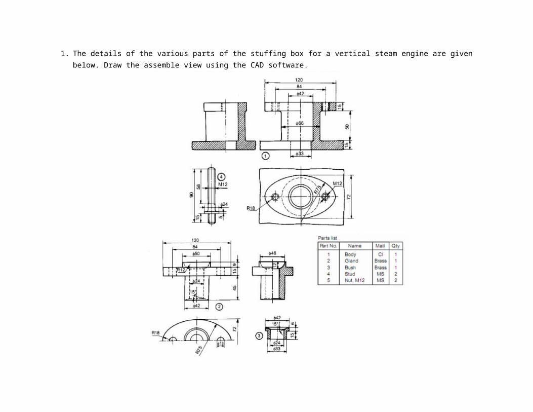
1. The details of the various parts of the stuffing box for a vertical steam engine are given below. Draw the assemble view using the CAD software.
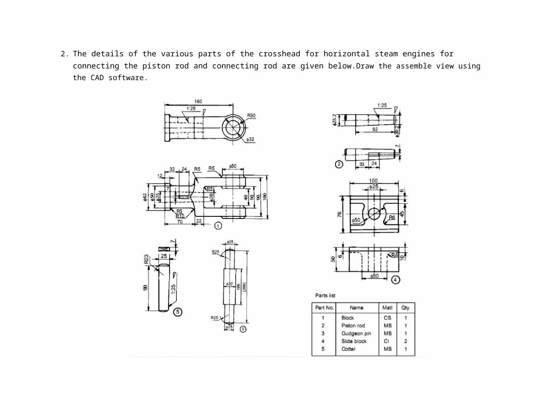
2. The details of the various parts of the crosshead for horizontal steam engines for connecting the piston rod and connecting rod are given below.Draw the assemble view using the CAD software.
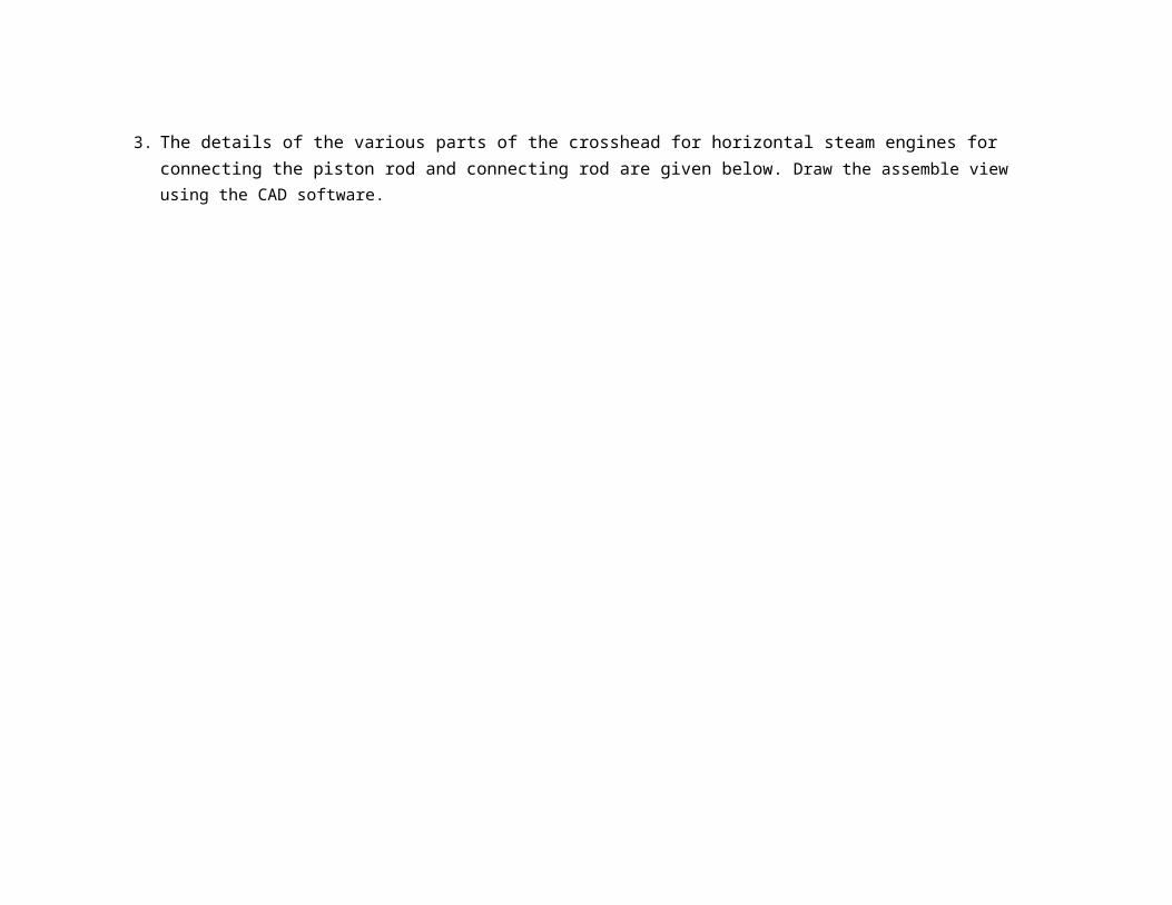
3. The details of the various parts of the crosshead for horizontal steam engines for connecting the piston rod and connecting rod are given below. Draw the assemble view using the CAD software.
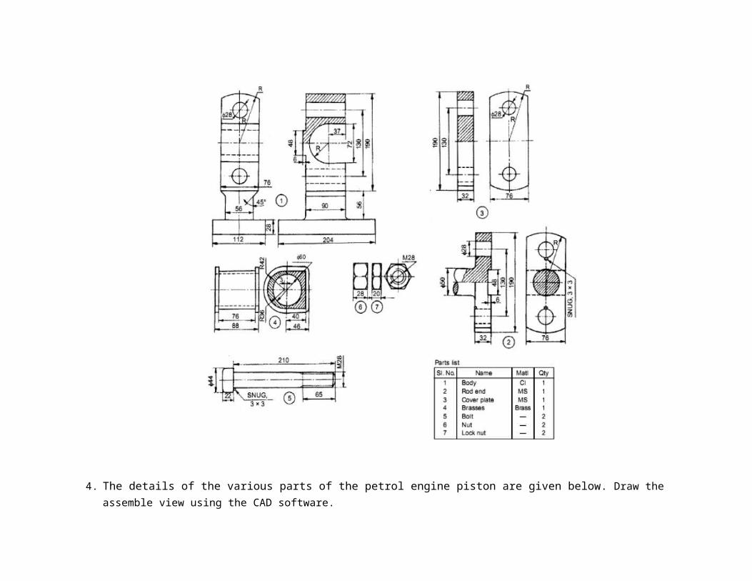
4. The details of the various parts of the petrol engine piston are given below. Draw the assemble view using the CAD software.
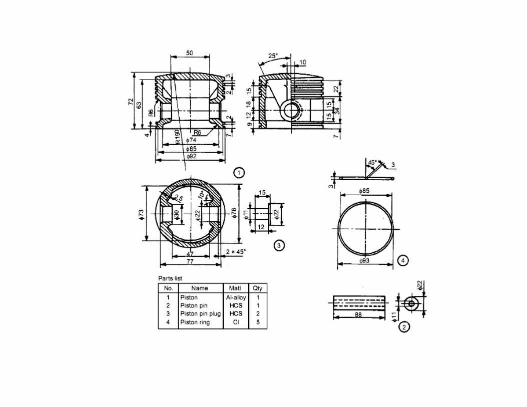
5. The details of the various parts of the non-return valve are given below.Draw the assemble view using the CAD software.

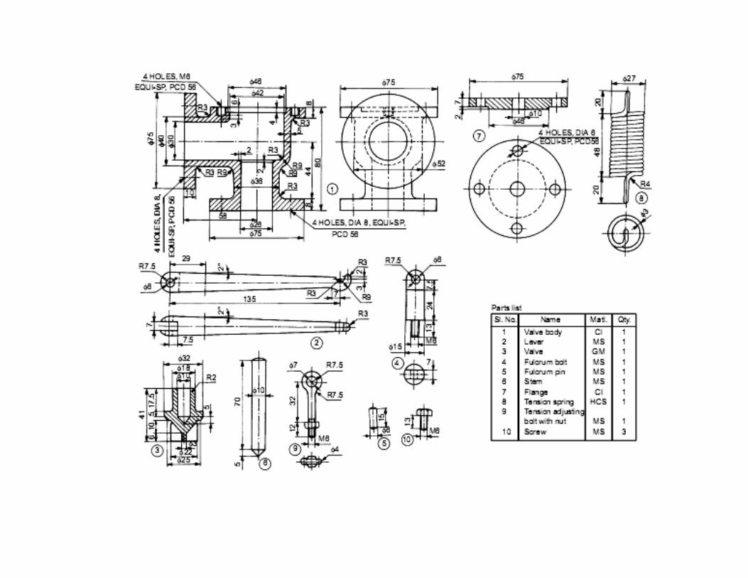
6. The details of the various parts of the spring loaded relief valve are given below.Draw the assemble view using the CAD software.
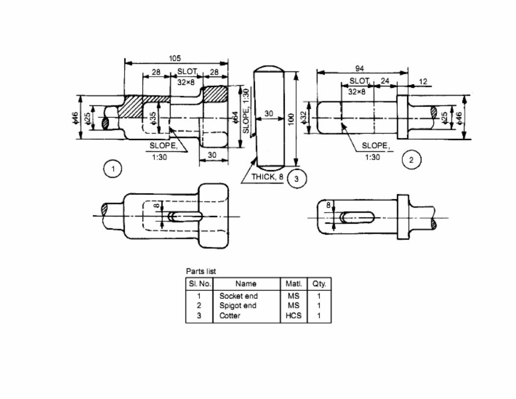
7. The details of the various parts of the socket and spigot joint are given below. Draw the assemble view using the CAD software.
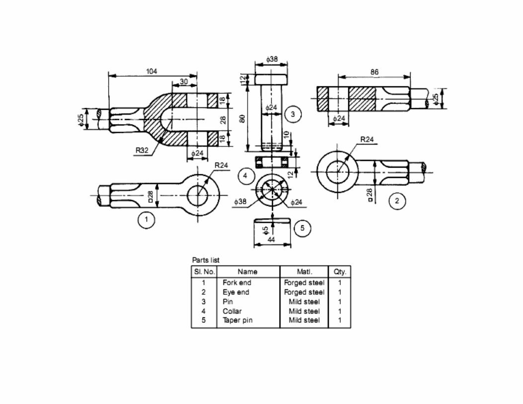
8. The details of the various parts of the knuckle joint are given below. Draw the assemble view using the CAD software.
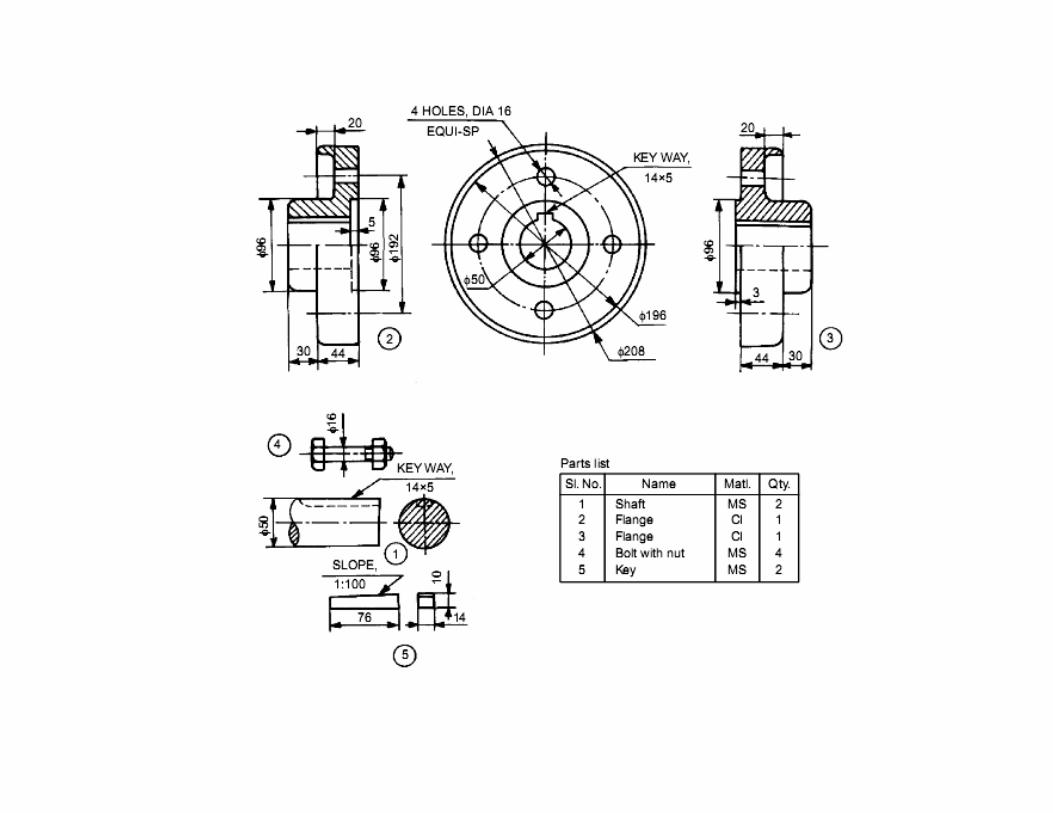
9. The details of the various parts of the protected flanged coupling are given below.Draw the assemble view using the CAD software.
10. The details of the various parts of the Oldham coupling are given below.Draw the assemble view using the CAD software.
11. The details of the various parts of the universal coupling are given below. Draw the assemble view using the CAD software.
12. The details of the various parts of the Plummer block are given below. Draw the assemble view using the CAD software.
13. The details of the various parts of the foot-step bearing are given below. Draw the assemble view using the CAD software.
14. The details of the various parts of the Screw jacks are given below. Draw the assemble view using the CAD software.
15. The details of the various parts of the Pipe vice are given below. Draw the assemble view using the CAD software.


![Sectional Views [Machine Drawing]](https://img.pdfslide.us/doc/110x75/55cf9ce4550346d033ab706a/sectional-views-machine-drawing.jpg)