Embed Size (px)
Citation preview
133
T E C H N I C A L D O C U M E N T A T I O N O - R I N G S
1 3 . O - r i n g A s s e m b l i n g C o n d i t i o n s
Installation tips
The following instructions must beobserved when installing O-rings:Assembly must be done with care sothat the O-ring is properly placed in thegroove and is not damaged when thegland is closed.
- Always check the O-ring elastomermaterial first. Briefly check the crosssection and inside diameter beforeinstalling the O-ring.
- Cleanliness is important for properseal action and long O-ring life.Foreign particles in the gland maycause leakage and can damage theO-ring .
- Never glue the O-rings in the groove;there is a risk for chemical attack andhardening. An alternative is to usemounting grease. First, however,check the chemical compatibility.
- For problem free assembly of O-ringsit is important that metal parts arerounded and free from sharp areas.Never force the O-ring over sharpthreads, keyways, slots and othersharp edges.
- Do not use sharp tools, use an O-ring assembling aid to avoid damage.
- ID stretch as installed in a groovemay not be more than 5-6%,because more stretch will reduceand flatten the cross section andthus reduce the squeeze.
- ID expansion to reach the grooveduring assembly should not exceed50%. For very small diameters, itmay be necessary to exceed thislimit. If so, one should allow suffi-cient time for the O-ring to return toits normal size before closing thegland.
- Prevent the O-ring from being twist-ed. Twisting during installation mayoccur with O-rings having a largeratio of ID to cross section.
- Check the roughness of the countersurface.
- For removal of O-rings use an O-ringtool kit to prevent the metal surfaceor O-ring from being damaged.
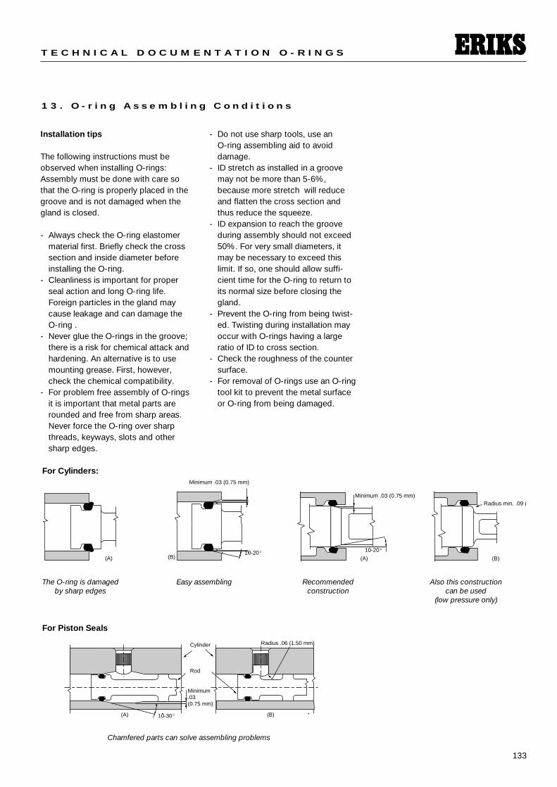
(A) (B)10-20° 10-20°
Minimum .03 (0.75 mm)
(A)
Radius min. .09 (
(B)
Minimum .03 (0.75 mm)
For Cylinders:
The O-ring is damaged by sharp edges
10-30°(A)
Minimum .03(0.75 mm)
(B)
Radius .06 (1.50 mm)
Rod
Cylinder
For Piston Seals
Chamfered parts can solve assembling problems
Easy assembling Recommended construction
Also this construction can be used
(low pressure only)
134
S E A L I N G E L E M E N T S
1 3 . O - r i n g A s s e m b l i n g C o n d i t i o n s
Lubrication For static and dynamic applicationslubricated parts are important for easeof assembly. Silicone grease is recom-mended for NBR, CR, FKM, EP, andVMQ.
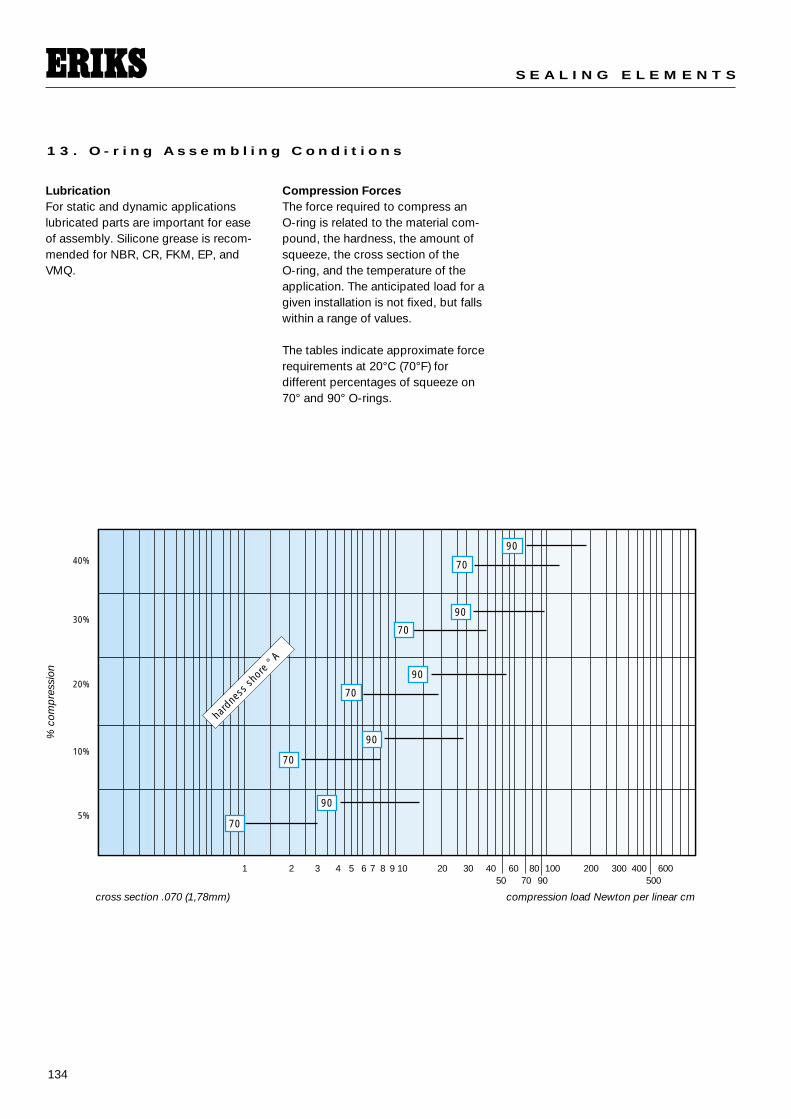
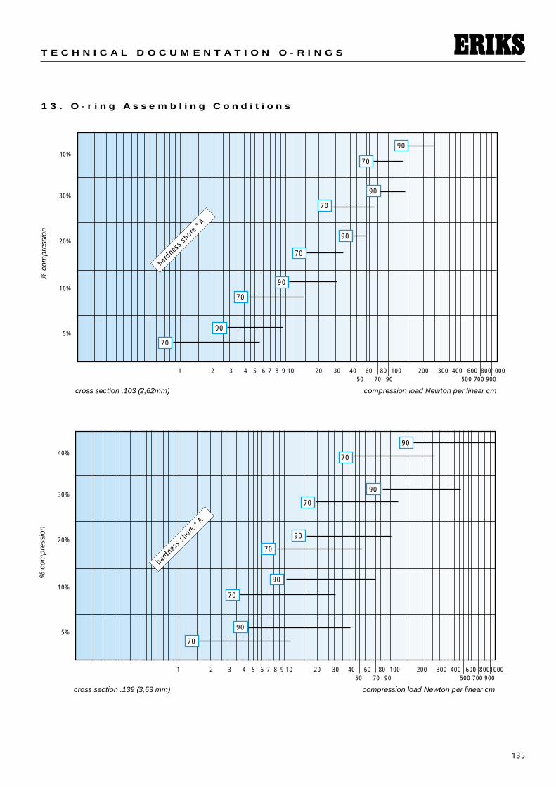
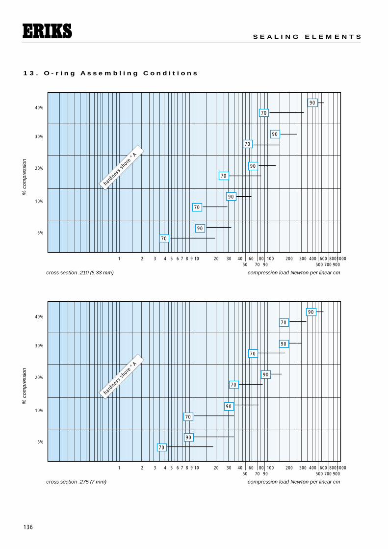
Compression ForcesThe force required to compress an O-ring is related to the material com-pound, the hardness, the amount ofsqueeze, the cross section of the O-ring, and the temperature of theapplication. The anticipated load for agiven installation is not fixed, but fallswithin a range of values.
The tables indicate approximate forcerequirements at 20°C (70°F) for different percentages of squeeze on70° and 90° O-rings.
1 2 3 4 5 6 7 8 9 10 20 30 40 60 80 100 200 300 400 60050 70 90 500
cross section .070 (1,78mm) compression load Newton per linear cm
% c
omp
ress
ion
hard
ness
shor
e °A
90
70
90
70
90
70
90
70
90
70
40%
30%
20%
10%
5%
135
T E C H N I C A L D O C U M E N T A T I O N O - R I N G S
1 2 3 4 5 6 7 8 9 10 20 30 40 60 80 100 200 300 400 600 800100050 70 90 500 700 900
cross section .139 (3,53 mm) compression load Newton per linear cm
% c
omp
ress
ion
hard
ness
shor
e °A
40%
30%
20%
10%
5%
1 2 3 4 5 6 7 8 9 10 20 30 40 60 80 100 200 300 400 600 800100050 70 90 500 700 900
cross section .103 (2,62mm) compression load Newton per linear cm
% c
omp
ress
ion
hard
ness
shor
e °A
40%
30%
20%
10%
5%
1 3 . O - r i n g A s s e m b l i n g C o n d i t i o n s
90
90
90
90
90
70
70
70
70
70
90
70
90
70
90
70
90
70
90
70
136
S E A L I N G E L E M E N T S
1 2 3 4 5 6 7 8 9 10 20 30 40 60 80 100 200 300 400 600 800100050 70 90 500 700 900
cross section .210 (5,33 mm) compression load Newton per linear cm
% c
omp
ress
ion
hard
ness
shor
e °A
40%
30%
20%
10%
5%
1 2 3 4 5 6 7 8 9 10 20 30 40 60 80 100 200 300 400 600 800100050 70 90 500 700 900
cross section .275 (7 mm) compression load Newton per linear cm
% c
omp
ress
ion
hard
ness
shor
e °A
40%
30%
20%
10%
5%
1 3 . O - r i n g A s s e m b l i n g C o n d i t i o n s
90
70
90
70
90
70
90
70
90
70
90
70
90
70
90
70
90
70
90
70
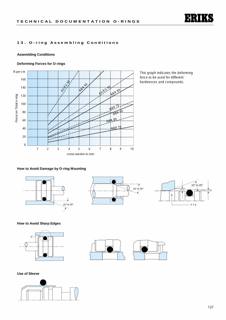
137
T E C H N I C A L D O C U M E N T A T I O N O - R I N G S
1 3 . O - r i n g A s s e m b l i n g C o n d i t i o n s
Assembling Conditions
Deforming Forces for O-rings
How to Avoid Damage by O-ring Mounting
1 2 3 4 5 6 7 8 9 10
160
140
120
100
80
60
40
20
0
cross section in mm
Forc
e on
Tot
al o
-rin
g
N per cm
AU/E
U 9
0
AU/EU 90NBR 9
0
NBR 80
NBR 80
NBR 70
NBR 70
NBR 90
15° to 20°
15° to 20°
x > y
15° to 20°
How to Avoid Sharp Edges
Use of Sleeve
‘Z’
This graph indicates the deformingforce to be used for different hardnesses and compounds.
138
S E A L I N G E L E M E N T S
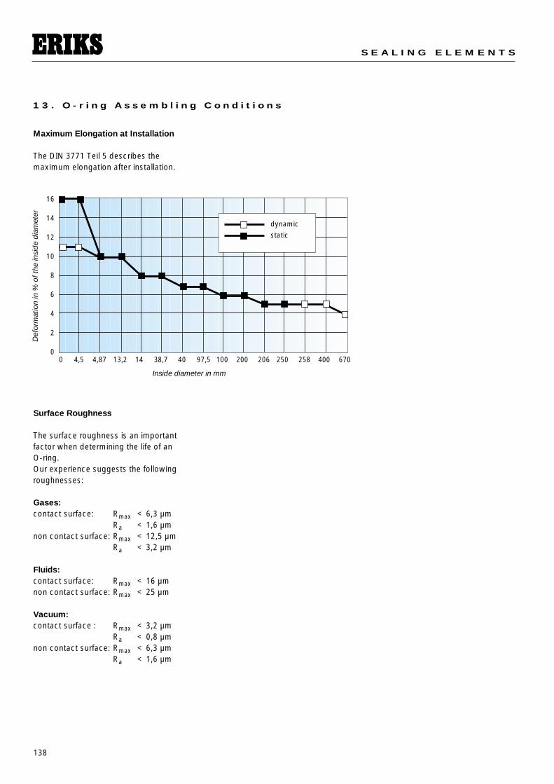
1 3 . O - r i n g A s s e m b l i n g C o n d i t i o n s
Maximum Elongation at Installation
The DIN 3771 Teil 5 describes themaximum elongation after installation.
Surface Roughness
The surface roughness is an importantfactor when determining the life of anO-ring.Our experience suggests the followingroughnesses:
Gases:contact surface: Rmax < 6,3 µm
Ra < 1,6 µmnon contact surface: Rmax < 12,5 µm
Ra < 3,2 µm
Fluids:contact surface: Rmax < 16 µmnon contact surface: Rmax < 25 µm
Vacuum:contact surface : Rmax < 3,2 µm
Ra < 0,8 µmnon contact surface: Rmax < 6,3 µm
Ra < 1,6 µm
0 4,5 4,87 13,2 14 38,7 40 97,5 100 200 206 250 258 400 670
16
14
12
10
8
6
4
2
0
Inside diameter in mm
Def
orm
atio
n in
% o
f the
insi
de
dia
met
er
dynamic
static
139
T E C H N I C A L D O C U M E N T A T I O N O - R I N G S
1 3 . O - r i n g A s s e m b l i n g C o n d i t i o n s
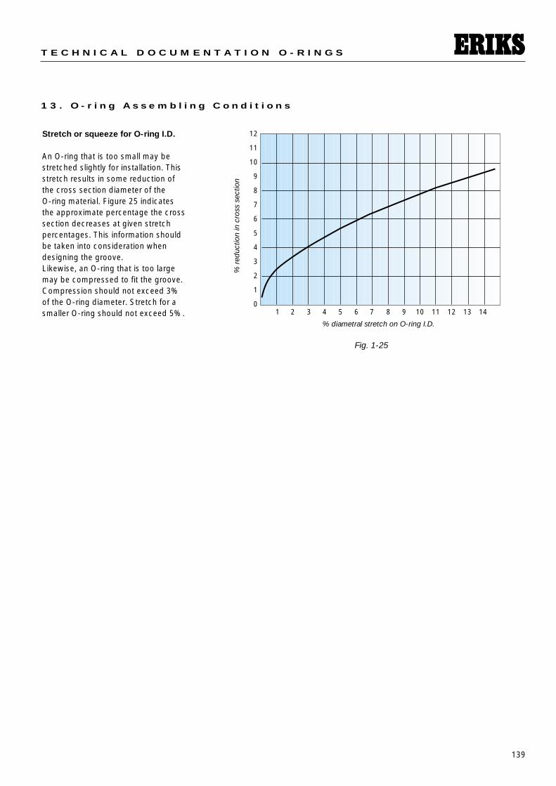
Stretch or squeeze for O-ring I.D.
An O-ring that is too small may bestretched slightly for installation. Thisstretch results in some reduction ofthe cross section diameter of the O-ring material. Figure 25 indicates the approximate percentage the crosssection decreases at given stretchpercentages. This information shouldbe taken into consideration whendesigning the groove.Likewise, an O-ring that is too largemay be compressed to fit the groove.Compression should not exceed 3%of the O-ring diameter. Stretch for asmaller O-ring should not exceed 5%.
Fig. 1-25
1 2 3 4 5 6 7 8 9 10 11 12 13 14
12
11
10
9
8
7
6
5
4
3
2
1
0
% diametral stretch on O-ring I.D.
% r
educ
tion
in c
ross
sec
tion
140
S E A L I N G E L E M E N T S
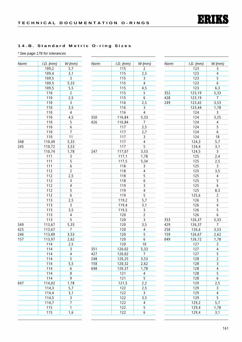
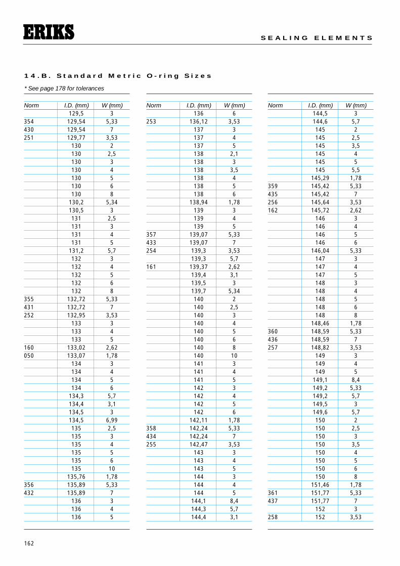
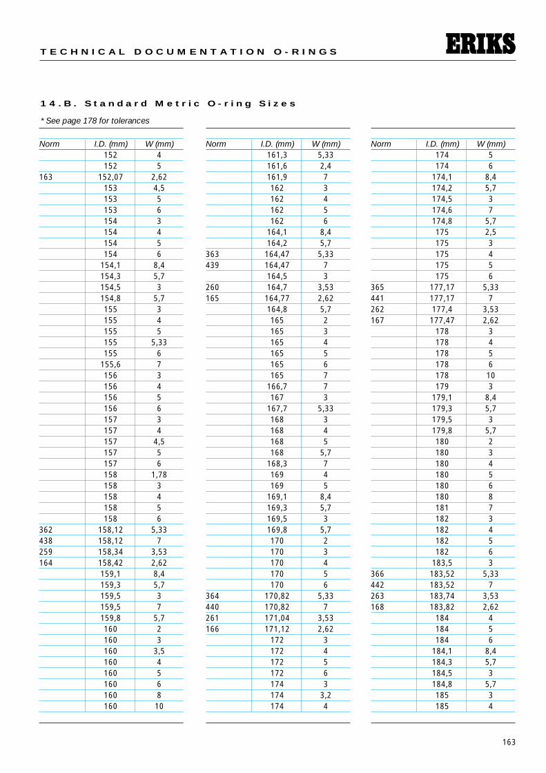
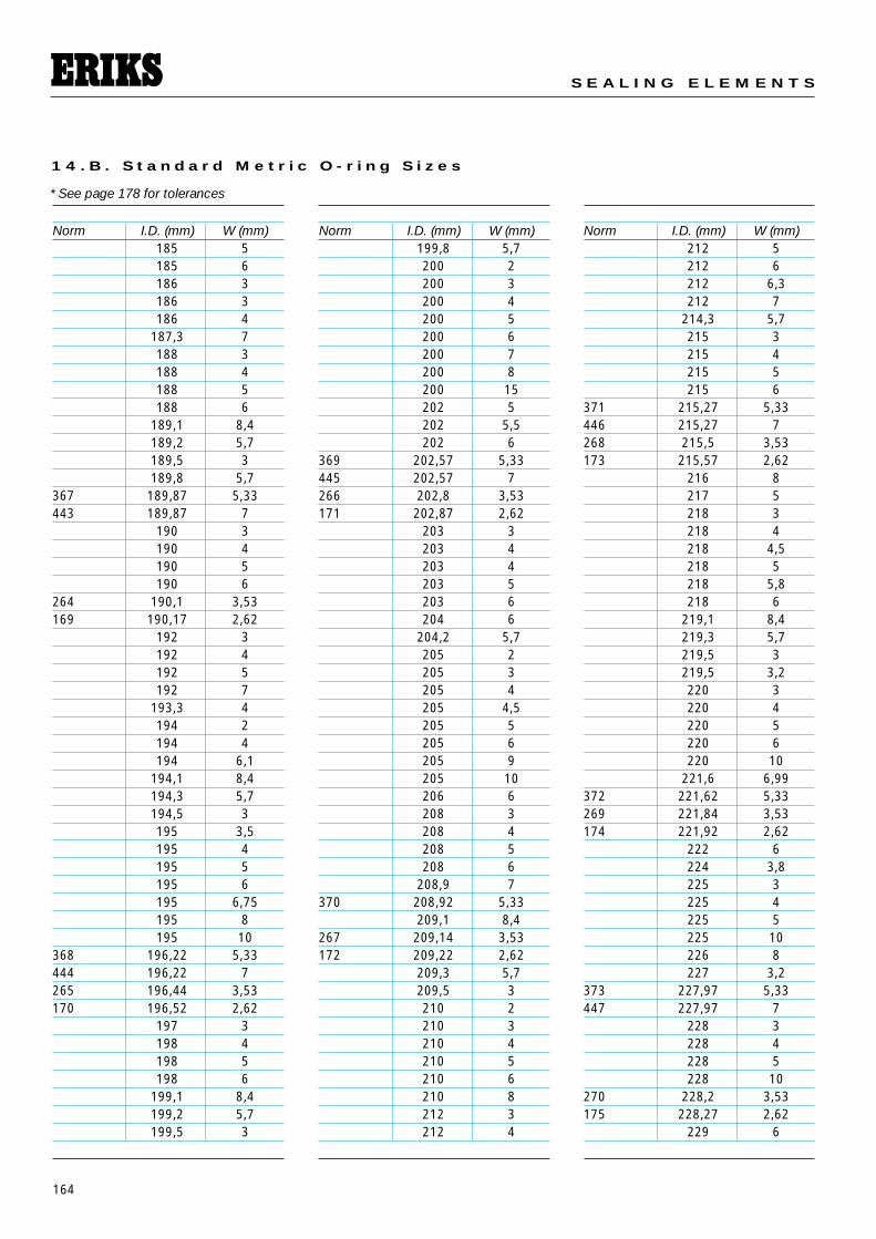
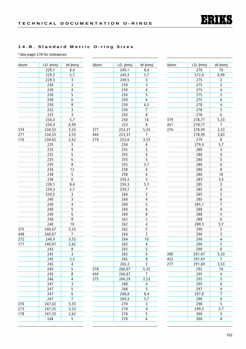
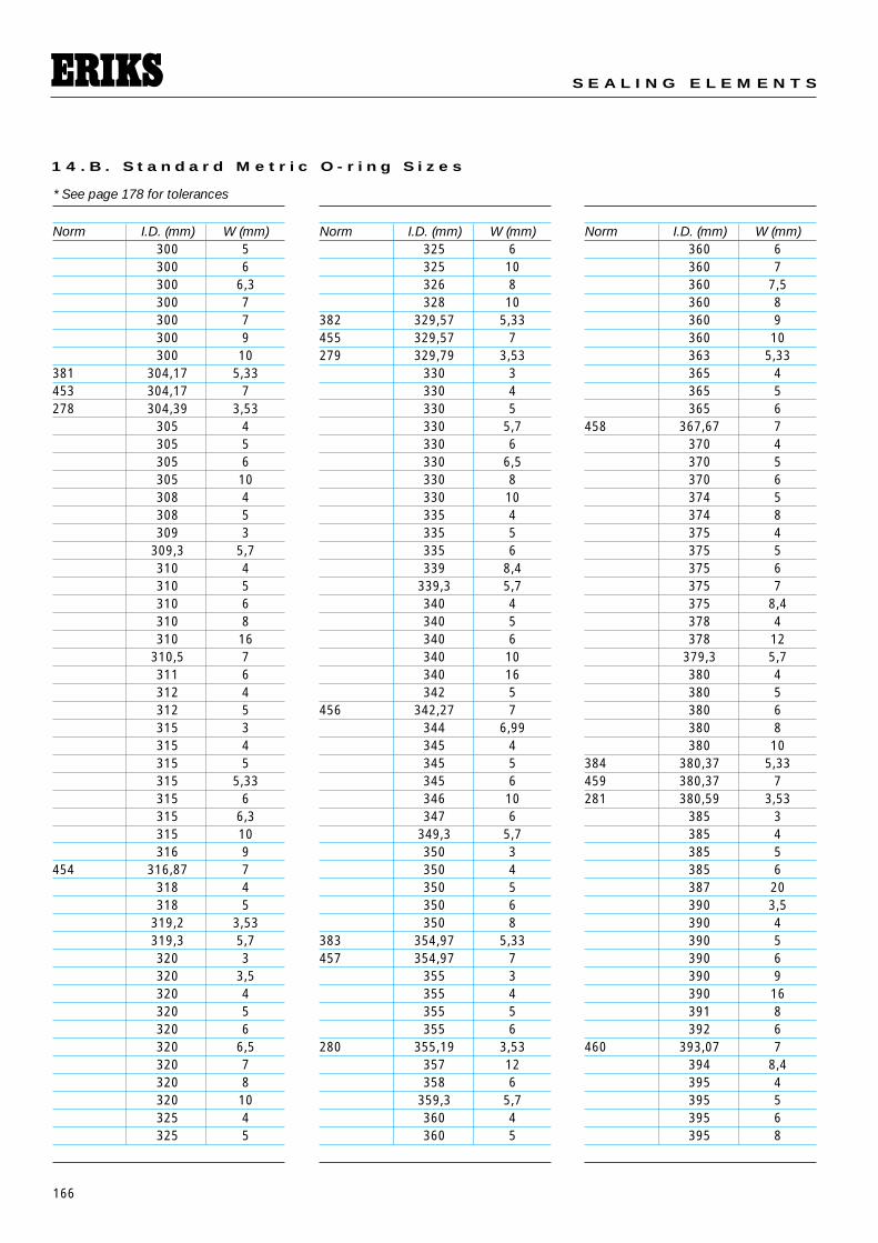
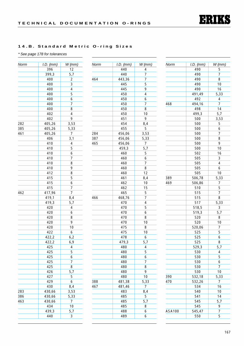
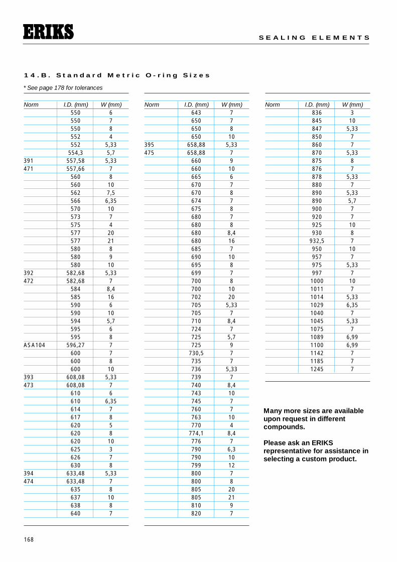
1 4 . O - r i n g S i z e C h a r t s
The following tables list approximately2000 O-ring sizes in order by insidediameter. These O-ring sizes correspondto US Standard AS568, BritishStandard, Swedish, as well as manycommon metric sizes according to DINand ISO standards. Most of thesesizes are readily available from ERIKSstock in:
• Nitrile NBR 70° and 90° Shore A, • Fluoroelastomer FKM (Viton®) 70°
and 90° Shore A, • Perfluoroelastomer FFKM
(Kalrez®) 75° Shore A.• Ethylene-propylene EP, EPDM 70°
shore A, • Silicone VMQ 70° Shore A, • PTFE (virgin teflon), • Teflex® FEP/FKM• Teflex® FEP/VMQ
The list of standards is continuallybeing expanded. Please contact thenearest ERIKS representative for sizesnot indicated here.
Note:The AS O-ring Size Chart has acolumn that shows the Nominal Sizealongside the Actual Size. Originallythe nominal size was just for a listingof the approximate fractional dimen-sions of the O-ring. Prior to the com-mon use of dial calipers many peoplecalled out a 1 inch by 1-1/4 rt = O-ring,this was a dash -214 O-ring. Theyused to also use these fractionaldimensions as the gland size. So, thenominal size is in fact based on thegland size and not the O-ring size.
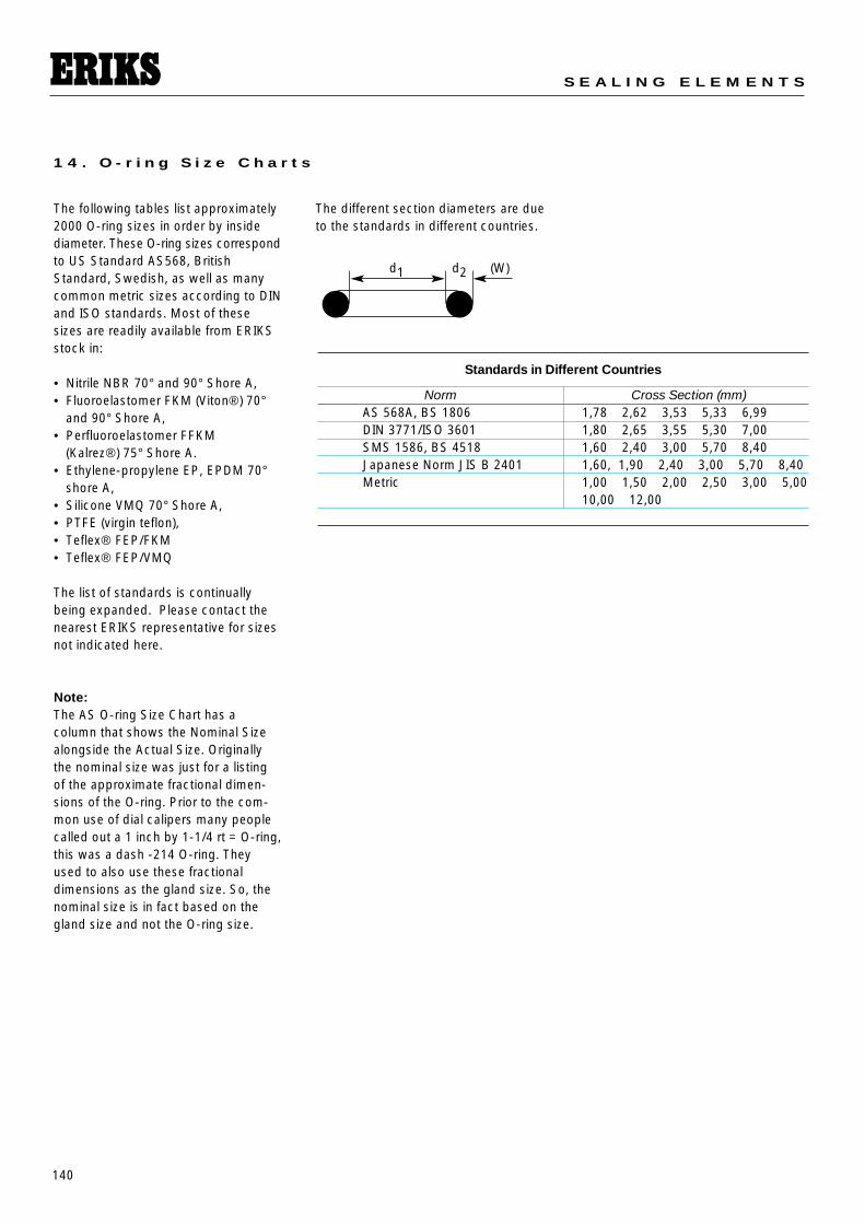
The different section diameters are dueto the standards in different countries.
Standards in Different Countries
Norm Cross Section (mm)AS 568A, BS 1806 1,78 2,62 3,53 5,33 6,99DIN 3771/ISO 3601 1,80 2,65 3,55 5,30 7,00SMS 1586, BS 4518 1,60 2,40 3,00 5,70 8,40Japanese Norm JIS B 2401 1,60, 1,90 2,40 3,00 5,70 8,40Metric 1,00 1,50 2,00 2,50 3,00 5,00
10,00 12,00
d2 (W)d1
141
T E C H N I C A L D O C U M E N T A T I O N O - R I N G S
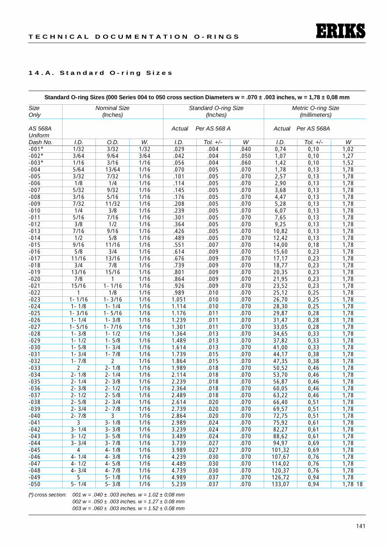
1 4 . A . S t a n d a r d O - r i n g S i z e s
Standard O-ring Sizes (000 Series 004 to 050 cross section Diameters w = .070 ± .003 inches, w = 1,78 ± 0,08 mm
Size Nominal Size Standard O-ring Size Metric O-ring SizeOnly (Inches) (Inches) (millimeters)
AS 568A Actual Per AS 568 A Actual Per AS 568AUniformDash No. I.D. O.D. W. I.D. Tol. +/- W I.D. Tol. +/- W-001* 1/32 3/32 1/32 .029 .004 .040 0,74 0,10 1,02-002* 3/64 9/64 3/64 .042 .004 .050 1,07 0,10 1,27-003* 1/16 3/16 1/16 .056 .004 .060 1,42 0,10 1,52-004 5/64 13/64 1/16 .070 .005 .070 1,78 0,13 1,78-005 3/32 7/32 1/16 .101 .005 .070 2,57 0,13 1,78-006 1/8 1/4 1/16 .114 .005 .070 2,90 0,13 1,78-007 5/32 9/32 1/16 .145 .005 .070 3,68 0,13 1,78-008 3/16 5/16 1/16 .176 .005 .070 4,47 0,13 1,78-009 7/32 11/32 1/16 .208 .005 .070 5,28 0,13 1,78-010 1/4 3/8 1/16 .239 .005 .070 6,07 0,13 1,78-011 5/16 7/16 1/16 .301 .005 .070 7,65 0,13 1,78-012 3/8 1/2 1/16 .364 .005 .070 9,25 0,13 1,78-013 7/16 9/16 1/16 .426 .005 .070 10,82 0,13 1,78-014 1/2 5/8 1/16 .489 .005 .070 12,42 0,13 1,78-015 9/16 11/16 1/16 .551 .007 .070 14,00 0,18 1,78-016 5/8 3/4 1/16 .614 .009 .070 15,60 0,23 1,78-017 11/16 13/16 1/16 .676 .009 .070 17,17 0,23 1,78-018 3/4 7/8 1/16 .739 .009 .070 18,77 0,23 1,78-019 13/16 15/16 1/16 .801 .009 .070 20,35 0,23 1,78-020 7/8 1 1/16 .864 .009 .070 21,95 0,23 1,78-021 15/16 1- 1/16 1/16 .926 .009 .070 23,52 0,23 1,78-022 1 1/8 1/16 .989 .010 .070 25,12 0,25 1,78-023 1- 1/16 1- 3/16 1/16 1.051 .010 .070 26,70 0,25 1,78-024 1- 1/8 1- 1/4 1/16 1.114 .010 .070 28,30 0,25 1,78-025 1- 3/16 1- 5/16 1/16 1.176 .011 .070 29,87 0,28 1,78-026 1- 1/4 1- 3/8 1/16 1.239 .011 .070 31,47 0,28 1,78-027 1- 5/16 1- 7/16 1/16 1.301 .011 .070 33,05 0,28 1,78-028 1- 3/8 1- 1/2 1/16 1.364 .013 .070 34,65 0,33 1,78-029 1- 1/2 1- 5/8 1/16 1.489 .013 .070 37,82 0,33 1,78-030 1- 5/8 1- 3/4 1/16 1.614 .013 .070 41,00 0,33 1,78-031 1- 3/4 1- 7/8 1/16 1.739 .015 .070 44,17 0,38 1,78-032 1- 7/8 2 1/16 1.864 .015 .070 47,35 0,38 1,78-033 2 2- 1/8 1/16 1.989 .018 .070 50,52 0,46 1,78-034 2- 1/8 2- 1/4 1/16 2.114 .018 .070 53,70 0,46 1,78-035 2- 1/4 2- 3/8 1/16 2.239 .018 .070 56,87 0,46 1,78-036 2- 3/8 2- 1/2 1/16 2.364 .018 .070 60,05 0,46 1,78-037 2- 1/2 2- 5/8 1/16 2.489 .018 .070 63,22 0,46 1,78-038 2- 5/8 2- 3/4 1/16 2.614 .020 .070 66,40 0,51 1,78-039 2- 3/4 2- 7/8 1/16 2.739 .020 .070 69,57 0,51 1,78-040 2- 7/8 3 1/16 2.864 .020 .070 72,75 0,51 1,78-041 3 3- 1/8 1/16 2.989 .024 .070 75,92 0,61 1,78-042 3- 1/4 3- 3/8 1/16 3.239 .024 .070 82,27 0,61 1,78-043 3- 1/2 3- 5/8 1/16 3.489 .024 .070 88,62 0,61 1,78-044 3- 3/4 3- 7/8 1/16 3.739 .027 .070 94,97 0,69 1,78-045 4 4- 1/8 1/16 3.989 .027 .070 101,32 0,69 1,78-046 4- 1/4 4- 3/8 1/16 4.239 .030 .070 107,67 0,76 1,78-047 4- 1/2 4- 5/8 1/16 4.489 .030 .070 114,02 0,76 1,78-048 4- 3/4 4- 7/8 1/16 4.739 .030 .070 120,37 0,76 1,78-049 5 5- 1/8 1/16 4.989 .037 .070 126,72 0,94 1,78-050 5- 1/4 5- 3/8 1/16 5.239 .037 .070 133,07 0,94 1,78 18
(*) cross section: 001 w = .040 ± .003 inches. w = 1.02 ± 0;08 mm002 w = .050 ± .003 inches. w = 1.27 ± 0.08 mm003 w = .060 ± .003 inches. w = 1.52 ± 0.08 mm
142
S E A L I N G E L E M E N T S
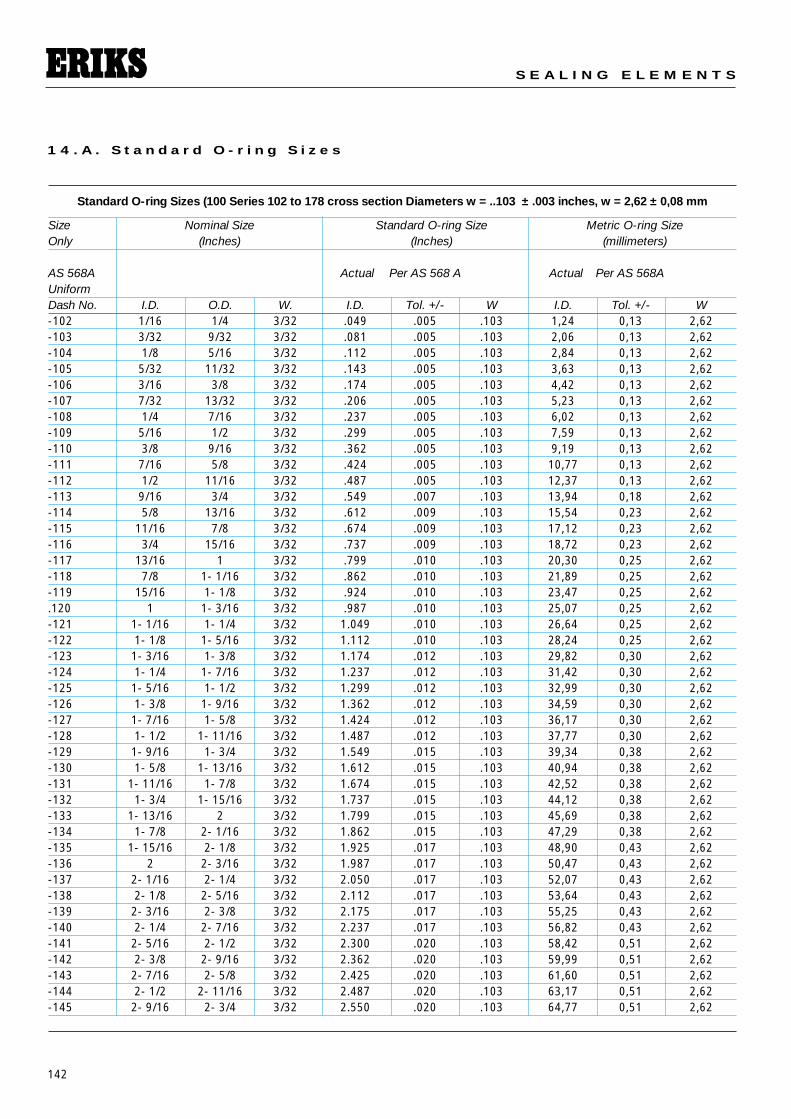
1 4 . A . S t a n d a r d O - r i n g S i z e s
Standard O-ring Sizes (100 Series 102 to 178 cross section Diameters w = ..103 ± .003 inches, w = 2,62 ± 0,08 mm
Size Nominal Size Standard O-ring Size Metric O-ring SizeOnly (Inches) (Inches) (millimeters)
AS 568A Actual Per AS 568 A Actual Per AS 568AUniformDash No. I.D. O.D. W. I.D. Tol. +/- W I.D. Tol. +/- W-102 1/16 1/4 3/32 .049 .005 .103 1,24 0,13 2,62-103 3/32 9/32 3/32 .081 .005 .103 2,06 0,13 2,62-104 1/8 5/16 3/32 .112 .005 .103 2,84 0,13 2,62-105 5/32 11/32 3/32 .143 .005 .103 3,63 0,13 2,62-106 3/16 3/8 3/32 .174 .005 .103 4,42 0,13 2,62-107 7/32 13/32 3/32 .206 .005 .103 5,23 0,13 2,62-108 1/4 7/16 3/32 .237 .005 .103 6,02 0,13 2,62-109 5/16 1/2 3/32 .299 .005 .103 7,59 0,13 2,62-110 3/8 9/16 3/32 .362 .005 .103 9,19 0,13 2,62-111 7/16 5/8 3/32 .424 .005 .103 10,77 0,13 2,62-112 1/2 11/16 3/32 .487 .005 .103 12,37 0,13 2,62-113 9/16 3/4 3/32 .549 .007 .103 13,94 0,18 2,62-114 5/8 13/16 3/32 .612 .009 .103 15,54 0,23 2,62-115 11/16 7/8 3/32 .674 .009 .103 17,12 0,23 2,62-116 3/4 15/16 3/32 .737 .009 .103 18,72 0,23 2,62-117 13/16 1 3/32 .799 .010 .103 20,30 0,25 2,62-118 7/8 1- 1/16 3/32 .862 .010 .103 21,89 0,25 2,62-119 15/16 1- 1/8 3/32 .924 .010 .103 23,47 0,25 2,62.120 1 1- 3/16 3/32 .987 .010 .103 25,07 0,25 2,62-121 1- 1/16 1- 1/4 3/32 1.049 .010 .103 26,64 0,25 2,62-122 1- 1/8 1- 5/16 3/32 1.112 .010 .103 28,24 0,25 2,62-123 1- 3/16 1- 3/8 3/32 1.174 .012 .103 29,82 0,30 2,62-124 1- 1/4 1- 7/16 3/32 1.237 .012 .103 31,42 0,30 2,62-125 1- 5/16 1- 1/2 3/32 1.299 .012 .103 32,99 0,30 2,62-126 1- 3/8 1- 9/16 3/32 1.362 .012 .103 34,59 0,30 2,62-127 1- 7/16 1- 5/8 3/32 1.424 .012 .103 36,17 0,30 2,62-128 1- 1/2 1- 11/16 3/32 1.487 .012 .103 37,77 0,30 2,62-129 1- 9/16 1- 3/4 3/32 1.549 .015 .103 39,34 0,38 2,62-130 1- 5/8 1- 13/16 3/32 1.612 .015 .103 40,94 0,38 2,62-131 1- 11/16 1- 7/8 3/32 1.674 .015 .103 42,52 0,38 2,62-132 1- 3/4 1- 15/16 3/32 1.737 .015 .103 44,12 0,38 2,62-133 1- 13/16 2 3/32 1.799 .015 .103 45,69 0,38 2,62-134 1- 7/8 2- 1/16 3/32 1.862 .015 .103 47,29 0,38 2,62-135 1- 15/16 2- 1/8 3/32 1.925 .017 .103 48,90 0,43 2,62-136 2 2- 3/16 3/32 1.987 .017 .103 50,47 0,43 2,62-137 2- 1/16 2- 1/4 3/32 2.050 .017 .103 52,07 0,43 2,62-138 2- 1/8 2- 5/16 3/32 2.112 .017 .103 53,64 0,43 2,62-139 2- 3/16 2- 3/8 3/32 2.175 .017 .103 55,25 0,43 2,62-140 2- 1/4 2- 7/16 3/32 2.237 .017 .103 56,82 0,43 2,62-141 2- 5/16 2- 1/2 3/32 2.300 .020 .103 58,42 0,51 2,62-142 2- 3/8 2- 9/16 3/32 2.362 .020 .103 59,99 0,51 2,62-143 2- 7/16 2- 5/8 3/32 2.425 .020 .103 61,60 0,51 2,62-144 2- 1/2 2- 11/16 3/32 2.487 .020 .103 63,17 0,51 2,62-145 2- 9/16 2- 3/4 3/32 2.550 .020 .103 64,77 0,51 2,62
143
T E C H N I C A L D O C U M E N T A T I O N O - R I N G S
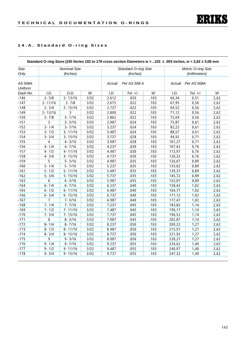
1 4 . A . S t a n d a r d O - r i n g S i z e s
Standard O-ring Sizes (100 Series 102 to 178 cross section Diameters w = ..103 ± .003 inches, w = 2,62 ± 0,08 mm
Size Nominal Size Standard O-ring Size Metric O-ring SizeOnly (Inches) (Inches) (millimeters)
AS 568A Actual Per AS 568 A Actual Per AS 568AUniformDash No. I.D. O.D. W. I.D. Tol. +/- W I.D. Tol. +/- W-146 2- 5/8 2- 13/16 3/32 2.612 .020 .103 66,34 0,51 2,62-147 2- 11/16 2- 7/8 3/32 2.675 .022 .103 67,95 0,56 2,62-148 2- 3/4 2- 15/16 3/32 2.737 .022 .103 69,52 0,56 2,62-149 2- 13/16 3 3/32 2.800 .022 .103 71,12 0,56 2,62-150 2- 7/8 3- 1/16 3/32 2.862 .022 .103 72,69 0,56 2,62-151 3 3- 3/16 3/32 2.987 .024 .103 75,87 0,61 2,62-152 3- 1/4 3- 7/16 3/32 3.237 .024 .103 82,22 0,61 2,62-153 3- 1/2 3- 11/16 3/32 3.487 .024 .103 88,57 0,61 2,62-154 3- 3/4 3- 15/16 3/32 3.737 .028 .103 94,92 0,71 2,62-155 4 4- 3/16 3/32 3.987 .028 .103 101,27 0,71 2,62-156 4- 1/4 4- 7/16 3/32 4.237 .030 .103 107,62 0,76 2,62-157 4- 1/2 4- 11/16 3/32 4.487 .030 .103 113,97 0,76 2,62-158 4- 3/4 4- 15/16 3/32 4.737 .030 .103 120,32 0,76 2,62-159 5 5- 3/16 3/32 4.987 .035 .103 126,67 0,89 2,62-160 5- 1/4 5- 7/16 3/32 5.237 .035 .103 133,02 0,89 2,62-161 5- 1/2 5- 11/16 3/32 5.487 .035 .103 139,37 0,89 2,62-162 5- 3/4 5- 15/16 3/32 5.737 .035 .103 145,72 0,89 2,62-163 6 6- 3/16 3/32 5.987 .035 .103 152,07 0,89 2,62-164 6- 1/4 6- 7/16 3/32 6.237 .040 .103 158,42 1,02 2,62-165 6- 1/2 6- 11/16 3/32 6.487 .040 .103 164,77 1,02 2,62-166 6- 3/4 6- 15/16 3/32 6.737 .040 .103 171,12 1,02 2,62-167 7 7- 3/16 3/32 6.987 .040 .103 177,47 1,02 2,62-168 7- 1/4 7- 7/16 3/32 7.237 .045 .103 183,82 1,14 2,62-169 7- 1/2 7- 11/16 3/32 7.487 .045 .103 190,17 1,14 2,62-170 7- 3/4 7- 15/16 3/32 7.737 .045 .103 196,52 1,14 2,62-171 8 8- 3/16 3/32 7.987 .045 .103 202,87 1,14 2,62-172 8- 1/4 8- 7/16 3/32 8.237 .050 .103 209,22 1,27 2,62-173 8- 1/2 8- 11/16 3/32 8.487 .050 .103 215,57 1,27 2,62-174 8- 3/4 8- 15/16 3/32 8.737 .050 .103 221,92 1,27 2,62-175 9 9- 3/16 3/32 8.987 .050 .103 228,27 1,27 2,62-176 9- 1/4 9- 7/16 3/32 9.237 .055 .103 234,62 1,40 2,62-177 9- 1/2 9- 11/16 3/32 9.487 .055 .103 240,97 1,40 2,62-178 9- 3/4 9- 15/16 3/32 9.737 .055 .103 247,32 1,40 2,62
144
S E A L I N G E L E M E N T S
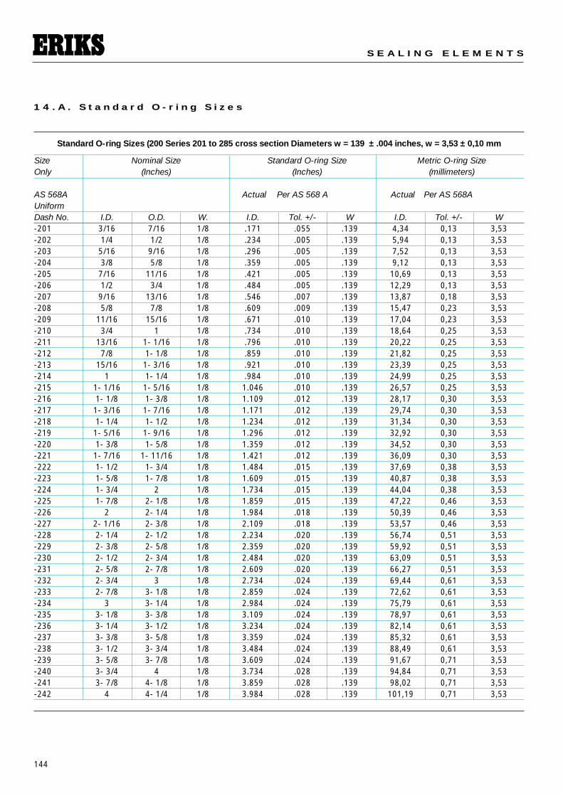
1 4 . A . S t a n d a r d O - r i n g S i z e s
Standard O-ring Sizes (200 Series 201 to 285 cross section Diameters w = 139 ± .004 inches, w = 3,53 ± 0,10 mm
Size Nominal Size Standard O-ring Size Metric O-ring SizeOnly (Inches) (Inches) (millimeters)
AS 568A Actual Per AS 568 A Actual Per AS 568AUniformDash No. I.D. O.D. W. I.D. Tol. +/- W I.D. Tol. +/- W-201 3/16 7/16 1/8 .171 .055 .139 4,34 0,13 3,53-202 1/4 1/2 1/8 .234 .005 .139 5,94 0,13 3,53-203 5/16 9/16 1/8 .296 .005 .139 7,52 0,13 3,53-204 3/8 5/8 1/8 .359 .005 .139 9,12 0,13 3,53-205 7/16 11/16 1/8 .421 .005 .139 10,69 0,13 3,53-206 1/2 3/4 1/8 .484 .005 .139 12,29 0,13 3,53-207 9/16 13/16 1/8 .546 .007 .139 13,87 0,18 3,53-208 5/8 7/8 1/8 .609 .009 .139 15,47 0,23 3,53-209 11/16 15/16 1/8 .671 .010 .139 17,04 0,23 3,53-210 3/4 1 1/8 .734 .010 .139 18,64 0,25 3,53-211 13/16 1- 1/16 1/8 .796 .010 .139 20,22 0,25 3,53-212 7/8 1- 1/8 1/8 .859 .010 .139 21,82 0,25 3,53-213 15/16 1- 3/16 1/8 .921 .010 .139 23,39 0,25 3,53-214 1 1- 1/4 1/8 .984 .010 .139 24,99 0,25 3,53-215 1- 1/16 1- 5/16 1/8 1.046 .010 .139 26,57 0,25 3,53-216 1- 1/8 1- 3/8 1/8 1.109 .012 .139 28,17 0,30 3,53-217 1- 3/16 1- 7/16 1/8 1.171 .012 .139 29,74 0,30 3,53-218 1- 1/4 1- 1/2 1/8 1.234 .012 .139 31,34 0,30 3,53-219 1- 5/16 1- 9/16 1/8 1.296 .012 .139 32,92 0,30 3,53-220 1- 3/8 1- 5/8 1/8 1.359 .012 .139 34,52 0,30 3,53-221 1- 7/16 1- 11/16 1/8 1.421 .012 .139 36,09 0,30 3,53-222 1- 1/2 1- 3/4 1/8 1.484 .015 .139 37,69 0,38 3,53-223 1- 5/8 1- 7/8 1/8 1.609 .015 .139 40,87 0,38 3,53-224 1- 3/4 2 1/8 1.734 .015 .139 44,04 0,38 3,53-225 1- 7/8 2- 1/8 1/8 1.859 .015 .139 47,22 0,46 3,53-226 2 2- 1/4 1/8 1.984 .018 .139 50,39 0,46 3,53-227 2- 1/16 2- 3/8 1/8 2.109 .018 .139 53,57 0,46 3,53-228 2- 1/4 2- 1/2 1/8 2.234 .020 .139 56,74 0,51 3,53-229 2- 3/8 2- 5/8 1/8 2.359 .020 .139 59,92 0,51 3,53-230 2- 1/2 2- 3/4 1/8 2.484 .020 .139 63,09 0,51 3,53-231 2- 5/8 2- 7/8 1/8 2.609 .020 .139 66,27 0,51 3,53-232 2- 3/4 3 1/8 2.734 .024 .139 69,44 0,61 3,53-233 2- 7/8 3- 1/8 1/8 2.859 .024 .139 72,62 0,61 3,53-234 3 3- 1/4 1/8 2.984 .024 .139 75,79 0,61 3,53-235 3- 1/8 3- 3/8 1/8 3.109 .024 .139 78,97 0,61 3,53-236 3- 1/4 3- 1/2 1/8 3.234 .024 .139 82,14 0,61 3,53-237 3- 3/8 3- 5/8 1/8 3.359 .024 .139 85,32 0,61 3,53-238 3- 1/2 3- 3/4 1/8 3.484 .024 .139 88,49 0,61 3,53-239 3- 5/8 3- 7/8 1/8 3.609 .024 .139 91,67 0,71 3,53-240 3- 3/4 4 1/8 3.734 .028 .139 94,84 0,71 3,53-241 3- 7/8 4- 1/8 1/8 3.859 .028 .139 98,02 0,71 3,53-242 4 4- 1/4 1/8 3.984 .028 .139 101,19 0,71 3,53
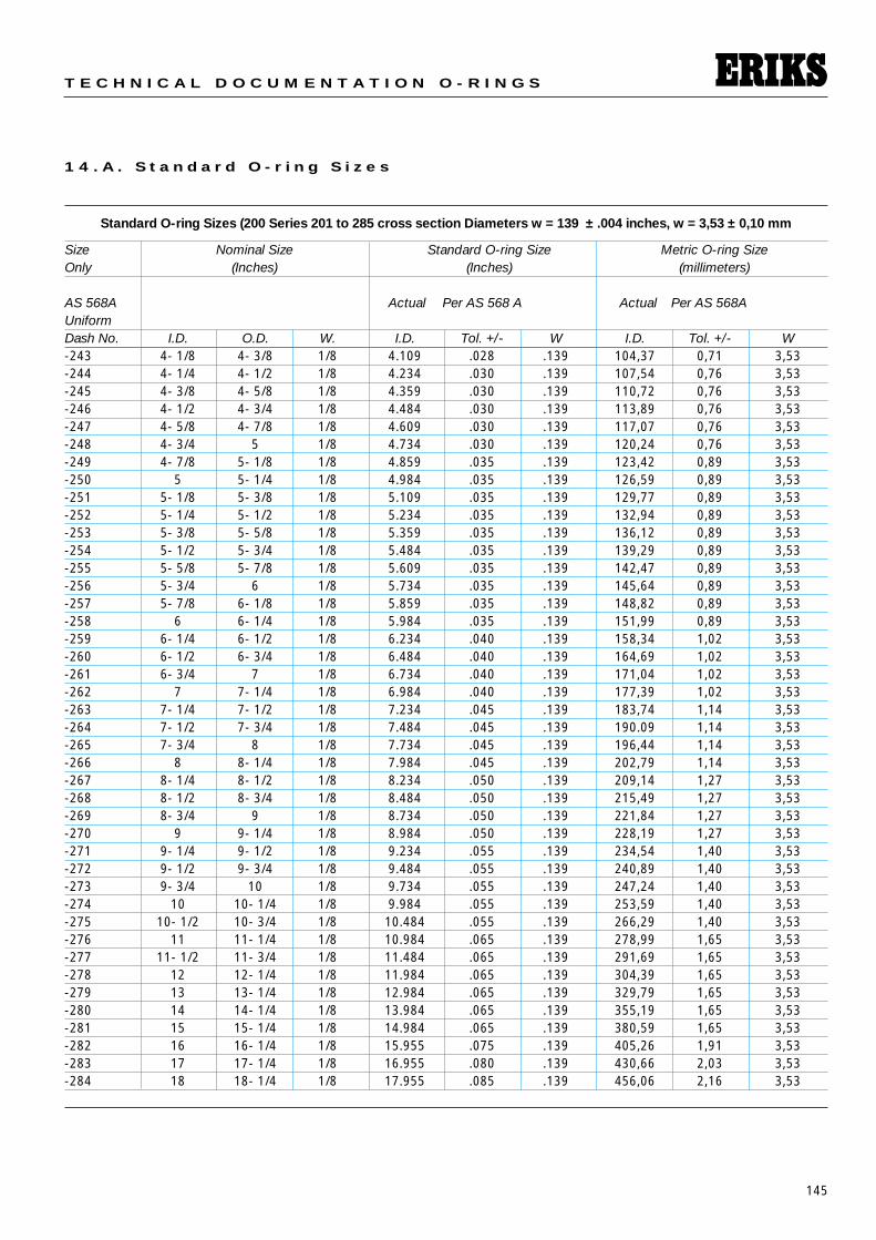
145
T E C H N I C A L D O C U M E N T A T I O N O - R I N G S
1 4 . A . S t a n d a r d O - r i n g S i z e s
Standard O-ring Sizes (200 Series 201 to 285 cross section Diameters w = 139 ± .004 inches, w = 3,53 ± 0,10 mm
Size Nominal Size Standard O-ring Size Metric O-ring SizeOnly (Inches) (Inches) (millimeters)
AS 568A Actual Per AS 568 A Actual Per AS 568AUniformDash No. I.D. O.D. W. I.D. Tol. +/- W I.D. Tol. +/- W-243 4- 1/8 4- 3/8 1/8 4.109 .028 .139 104,37 0,71 3,53-244 4- 1/4 4- 1/2 1/8 4.234 .030 .139 107,54 0,76 3,53-245 4- 3/8 4- 5/8 1/8 4.359 .030 .139 110,72 0,76 3,53-246 4- 1/2 4- 3/4 1/8 4.484 .030 .139 113,89 0,76 3,53-247 4- 5/8 4- 7/8 1/8 4.609 .030 .139 117,07 0,76 3,53-248 4- 3/4 5 1/8 4.734 .030 .139 120,24 0,76 3,53-249 4- 7/8 5- 1/8 1/8 4.859 .035 .139 123,42 0,89 3,53-250 5 5- 1/4 1/8 4.984 .035 .139 126,59 0,89 3,53-251 5- 1/8 5- 3/8 1/8 5.109 .035 .139 129,77 0,89 3,53-252 5- 1/4 5- 1/2 1/8 5.234 .035 .139 132,94 0,89 3,53-253 5- 3/8 5- 5/8 1/8 5.359 .035 .139 136,12 0,89 3,53-254 5- 1/2 5- 3/4 1/8 5.484 .035 .139 139,29 0,89 3,53-255 5- 5/8 5- 7/8 1/8 5.609 .035 .139 142,47 0,89 3,53-256 5- 3/4 6 1/8 5.734 .035 .139 145,64 0,89 3,53-257 5- 7/8 6- 1/8 1/8 5.859 .035 .139 148,82 0,89 3,53-258 6 6- 1/4 1/8 5.984 .035 .139 151,99 0,89 3,53-259 6- 1/4 6- 1/2 1/8 6.234 .040 .139 158,34 1,02 3,53-260 6- 1/2 6- 3/4 1/8 6.484 .040 .139 164,69 1,02 3,53-261 6- 3/4 7 1/8 6.734 .040 .139 171,04 1,02 3,53-262 7 7- 1/4 1/8 6.984 .040 .139 177,39 1,02 3,53-263 7- 1/4 7- 1/2 1/8 7.234 .045 .139 183,74 1,14 3,53-264 7- 1/2 7- 3/4 1/8 7.484 .045 .139 190.09 1,14 3,53-265 7- 3/4 8 1/8 7.734 .045 .139 196,44 1,14 3,53-266 8 8- 1/4 1/8 7.984 .045 .139 202,79 1,14 3,53-267 8- 1/4 8- 1/2 1/8 8.234 .050 .139 209,14 1,27 3,53-268 8- 1/2 8- 3/4 1/8 8.484 .050 .139 215,49 1,27 3,53-269 8- 3/4 9 1/8 8.734 .050 .139 221,84 1,27 3,53-270 9 9- 1/4 1/8 8.984 .050 .139 228,19 1,27 3,53-271 9- 1/4 9- 1/2 1/8 9.234 .055 .139 234,54 1,40 3,53-272 9- 1/2 9- 3/4 1/8 9.484 .055 .139 240,89 1,40 3,53-273 9- 3/4 10 1/8 9.734 .055 .139 247,24 1,40 3,53-274 10 10- 1/4 1/8 9.984 .055 .139 253,59 1,40 3,53-275 10- 1/2 10- 3/4 1/8 10.484 .055 .139 266,29 1,40 3,53-276 11 11- 1/4 1/8 10.984 .065 .139 278,99 1,65 3,53-277 11- 1/2 11- 3/4 1/8 11.484 .065 .139 291,69 1,65 3,53-278 12 12- 1/4 1/8 11.984 .065 .139 304,39 1,65 3,53-279 13 13- 1/4 1/8 12.984 .065 .139 329,79 1,65 3,53-280 14 14- 1/4 1/8 13.984 .065 .139 355,19 1,65 3,53-281 15 15- 1/4 1/8 14.984 .065 .139 380,59 1,65 3,53-282 16 16- 1/4 1/8 15.955 .075 .139 405,26 1,91 3,53-283 17 17- 1/4 1/8 16.955 .080 .139 430,66 2,03 3,53-284 18 18- 1/4 1/8 17.955 .085 .139 456,06 2,16 3,53
146
S E A L I N G E L E M E N T S
1 4 . A . S t a n d a r d O - r i n g S i z e s
Standard O-ring Sizes (300 Series 309 to 395 cross section Diameters w = .210 ± .005 inches, w = 5,33 ± 0,13 mm
Size Nominal Size Standard O-ring Size Metric O-ring SizeOnly (Inches) (Inches) (millimeters)
AS 568A Actual Per AS 568 A Actual Per AS 568AUniformDash No. I.D. O.D. W. I.D. Tol. +/- W I.D. Tol. +/- W-309 7/16 13/16 3/16 .412 .005 .210 10,46 0,13 5,33-310 1/2 7/8 3/16 .475 .005 .210 12,07 0,13 5,33-311 9/16 15/16 3/16 .537 .007 .210 13,64 0,18 5,33-312 5/8 1 3/16 .600 .009 .210 15,24 0,23 5,33-313 11/16 1- 1/16 3/16 .662 .009 .210 16,81 0,23 5,33-314 3/4 1- 1/8 3/16 .725 .010 .210 18,42 0,25 5,33-315 13/16 1- 3/16 3/16 .787 .010 .210 19,99 0,25 5,33-316 7/8 1- 1/4 3/16 .850 .010 .210 21,59 0,25 5,33-317 15/16 1- 5/16 3/16 .912 .010 .210 23,16 0,25 5,33-318 1 1- 3/8 3/16 .975 .010 .210 24,77 0,25 5,33-319 1- 1/16 1- 7/16 3/16 1.037 .010 .210 26,34 0,25 5,33-320 1- 1/8 1- 1/2 3/16 1.100 .012 .210 27,94 0,30 5,33-321 1- 3/16 1- 9/16 3/16 1.162 .012 .210 29,51 0,30 5,33-322 1- 1/4 1- 5/8 3/16 1.225 .012 .210 31,12 0,30 5,33-323 1- 5/16 1- 11/16 3/16 1.287 .012 .210 32,69 0,30 5,33-324 1- 3/8 1- 3/4 3/16 1.350 .012 .210 34,29 0,30 5,33-325 1- 1/2 1- 7/8 3/16 1.475 .015 .210 37,47 0,38 5,33-326 1- 5/8 2 3/16 1.600 .015 .210 40,64 0,38 5,33-327 1- 3/4 2- 1/8 3/16 1.725 .015 .210 43,82 0,38 5,33-328 1- 7/8 2- 1/4 3/16 1.850 .015 .210 46,99 0,38 5,33-329 2 2- 3/8 3/16 1.975 .018 .210 50,17 0,46 5,33-330 2- 1/8 2- 1/2 3/16 2.100 .018 .210 53,34 0,46 5,33-331 2- 1/4 2- 5/8 3/16 2.225 .018 .210 56,52 0,46 5,33-332 2- 3/8 2- 3/4 3/16 2.350 .018 .210 59,69 0,46 5,33-333 2- 1/2 2- 7/8 3/16 2.475 .020 .210 62,87 0,51 5,33-334 2- 5/8 3 3/16 2.600 .020 .210 66.04 0.51 5,33-335 2- 3/4 3- 1/8 3/16 2.725 .020 .210 69,22 0,51 5,33-336 2- 7/8 3- 1/4 3/16 2.850 .020 .210 72,39 0,51 5,33-337 3 3- 3/8 3/16 2.975 .024 .210 75,37 0,61 5,33-338 3- 1/8 3- 1/2 3/16 3.100 .024 .210 78,74 0,61 5,33-339 3- 1/4 3- 5/8 3/16 3.225 .024 .210 81,92 0,61 5,33-340 3- 3/8 3- 3/4 3/16 3.350 .024 .210 85,09 0,61 5,33-341 3- 1/2 3- 7/8 3/16 3.475 .024 .210 88,27 0,61 5,33-342 3- 5/8 4 3/16 3.600 .028 .210 91,44 0,71 5,33-343 3- 3/4 4- 1/8 3/16 3.725 .028 .210 94,62 0,71 5,33-344 3- 7/8 4- 1/4 3/16 3.850 .028 .210 97,79 0,71 5,33-345 4 4- 3/8 3/16 3.975 .028 .210 100,97 0,71 5,33-346 4- 1/8 4- 1/2 3/16 4.100 .028 .210 104,14 0,71 5,33-347 4- 1/4 4- 5/8 3/16 4.225 .030 .210 107,32 0,76 5,33-348 4- 3/8 4- 3/4 3/16 4.350 .030 .210 110,49 0,76 5,33-349 4- 1/2 4- 7/8 3/16 4.475 .030 .210 113,67 0,76 5,33-350 4- 5/8 5 3/16 4.600 .030 .210 116,84 0,76 5,33-351 4- 3/4 5- 1/8 3/16 4.725 .030 .210 120,02 0,76 5,33-352 4- 7/8 5- 1/4 3/16 4.850 .030 .210 123,19 0,76 5,33
147
T E C H N I C A L D O C U M E N T A T I O N O - R I N G S
1 4 . A . S t a n d a r d O - r i n g S i z e s
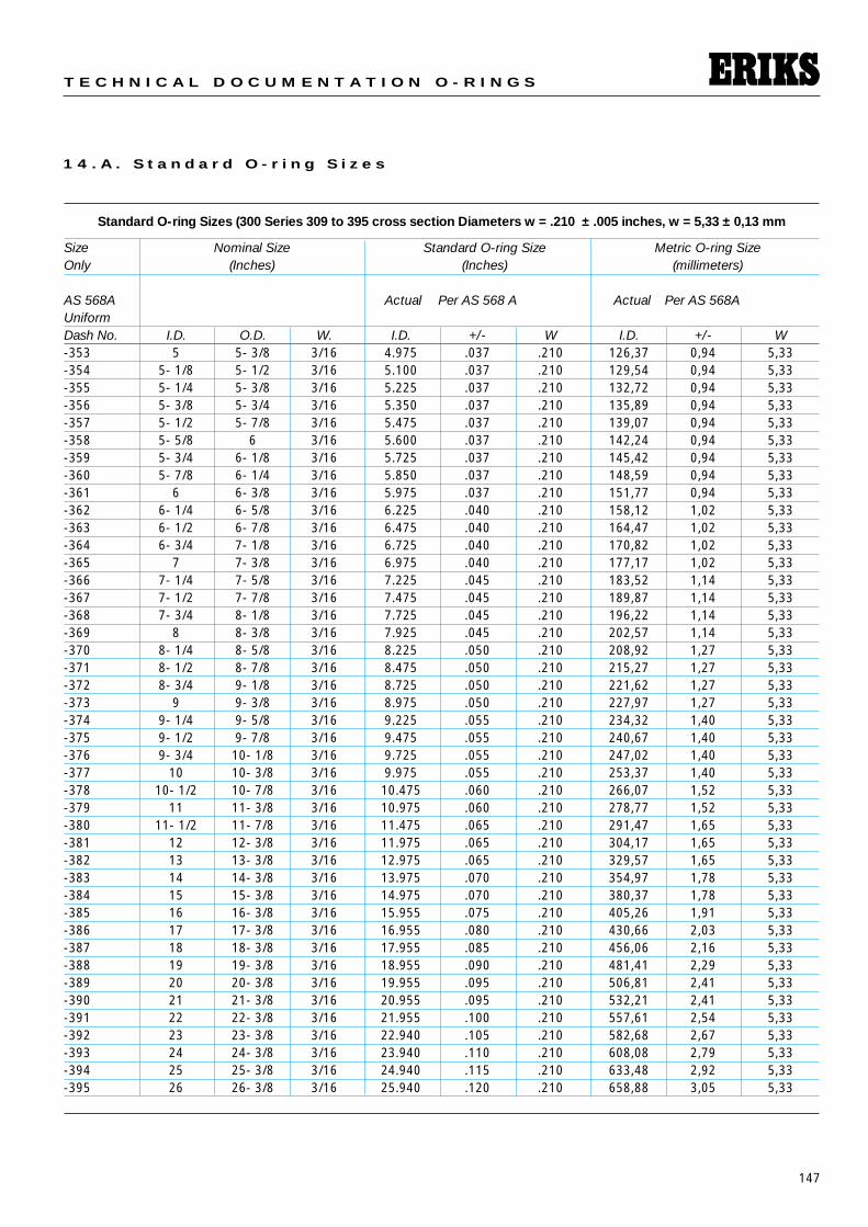
Standard O-ring Sizes (300 Series 309 to 395 cross section Diameters w = .210 ± .005 inches, w = 5,33 ± 0,13 mm
Size Nominal Size Standard O-ring Size Metric O-ring SizeOnly (Inches) (Inches) (millimeters)
AS 568A Actual Per AS 568 A Actual Per AS 568AUniformDash No. I.D. O.D. W. I.D. +/- W I.D. +/- W-353 5 5- 3/8 3/16 4.975 .037 .210 126,37 0,94 5,33-354 5- 1/8 5- 1/2 3/16 5.100 .037 .210 129,54 0,94 5,33-355 5- 1/4 5- 3/8 3/16 5.225 .037 .210 132,72 0,94 5,33-356 5- 3/8 5- 3/4 3/16 5.350 .037 .210 135,89 0,94 5,33-357 5- 1/2 5- 7/8 3/16 5.475 .037 .210 139,07 0,94 5,33-358 5- 5/8 6 3/16 5.600 .037 .210 142,24 0,94 5,33-359 5- 3/4 6- 1/8 3/16 5.725 .037 .210 145,42 0,94 5,33-360 5- 7/8 6- 1/4 3/16 5.850 .037 .210 148,59 0,94 5,33-361 6 6- 3/8 3/16 5.975 .037 .210 151,77 0,94 5,33-362 6- 1/4 6- 5/8 3/16 6.225 .040 .210 158,12 1,02 5,33-363 6- 1/2 6- 7/8 3/16 6.475 .040 .210 164,47 1,02 5,33-364 6- 3/4 7- 1/8 3/16 6.725 .040 .210 170,82 1,02 5,33-365 7 7- 3/8 3/16 6.975 .040 .210 177,17 1,02 5,33-366 7- 1/4 7- 5/8 3/16 7.225 .045 .210 183,52 1,14 5,33-367 7- 1/2 7- 7/8 3/16 7.475 .045 .210 189,87 1,14 5,33-368 7- 3/4 8- 1/8 3/16 7.725 .045 .210 196,22 1,14 5,33-369 8 8- 3/8 3/16 7.925 .045 .210 202,57 1,14 5,33-370 8- 1/4 8- 5/8 3/16 8.225 .050 .210 208,92 1,27 5,33-371 8- 1/2 8- 7/8 3/16 8.475 .050 .210 215,27 1,27 5,33-372 8- 3/4 9- 1/8 3/16 8.725 .050 .210 221,62 1,27 5,33-373 9 9- 3/8 3/16 8.975 .050 .210 227,97 1,27 5,33-374 9- 1/4 9- 5/8 3/16 9.225 .055 .210 234,32 1,40 5,33-375 9- 1/2 9- 7/8 3/16 9.475 .055 .210 240,67 1,40 5,33-376 9- 3/4 10- 1/8 3/16 9.725 .055 .210 247,02 1,40 5,33-377 10 10- 3/8 3/16 9.975 .055 .210 253,37 1,40 5,33-378 10- 1/2 10- 7/8 3/16 10.475 .060 .210 266,07 1,52 5,33-379 11 11- 3/8 3/16 10.975 .060 .210 278,77 1,52 5,33-380 11- 1/2 11- 7/8 3/16 11.475 .065 .210 291,47 1,65 5,33-381 12 12- 3/8 3/16 11.975 .065 .210 304,17 1,65 5,33-382 13 13- 3/8 3/16 12.975 .065 .210 329,57 1,65 5,33-383 14 14- 3/8 3/16 13.975 .070 .210 354,97 1,78 5,33-384 15 15- 3/8 3/16 14.975 .070 .210 380,37 1,78 5,33-385 16 16- 3/8 3/16 15.955 .075 .210 405,26 1,91 5,33-386 17 17- 3/8 3/16 16.955 .080 .210 430,66 2,03 5,33-387 18 18- 3/8 3/16 17.955 .085 .210 456,06 2,16 5,33-388 19 19- 3/8 3/16 18.955 .090 .210 481,41 2,29 5,33-389 20 20- 3/8 3/16 19.955 .095 .210 506,81 2,41 5,33-390 21 21- 3/8 3/16 20.955 .095 .210 532,21 2,41 5,33-391 22 22- 3/8 3/16 21.955 .100 .210 557,61 2,54 5,33-392 23 23- 3/8 3/16 22.940 .105 .210 582,68 2,67 5,33-393 24 24- 3/8 3/16 23.940 .110 .210 608,08 2,79 5,33-394 25 25- 3/8 3/16 24.940 .115 .210 633,48 2,92 5,33-395 26 26- 3/8 3/16 25.940 .120 .210 658,88 3,05 5,33
148
S E A L I N G E L E M E N T S
1 4 . A . S t a n d a r d O - r i n g S i z e s
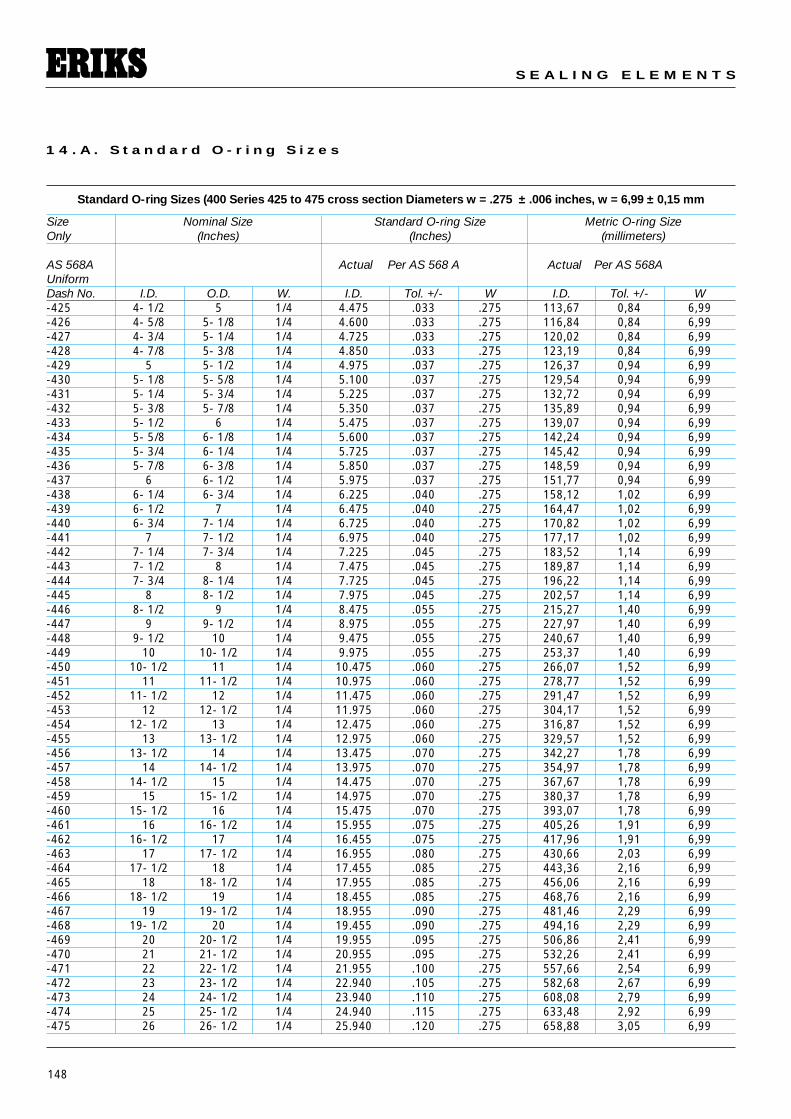
Standard O-ring Sizes (400 Series 425 to 475 cross section Diameters w = .275 ± .006 inches, w = 6,99 ± 0,15 mm
Size Nominal Size Standard O-ring Size Metric O-ring SizeOnly (Inches) (Inches) (millimeters)
AS 568A Actual Per AS 568 A Actual Per AS 568AUniformDash No. I.D. O.D. W. I.D. Tol. +/- W I.D. Tol. +/- W-425 4- 1/2 5 1/4 4.475 .033 .275 113,67 0,84 6,99-426 4- 5/8 5- 1/8 1/4 4.600 .033 .275 116,84 0,84 6,99-427 4- 3/4 5- 1/4 1/4 4.725 .033 .275 120,02 0,84 6,99-428 4- 7/8 5- 3/8 1/4 4.850 .033 .275 123,19 0,84 6,99-429 5 5- 1/2 1/4 4.975 .037 .275 126,37 0,94 6,99-430 5- 1/8 5- 5/8 1/4 5.100 .037 .275 129,54 0,94 6,99-431 5- 1/4 5- 3/4 1/4 5.225 .037 .275 132,72 0,94 6,99-432 5- 3/8 5- 7/8 1/4 5.350 .037 .275 135,89 0,94 6,99-433 5- 1/2 6 1/4 5.475 .037 .275 139,07 0,94 6,99-434 5- 5/8 6- 1/8 1/4 5.600 .037 .275 142,24 0,94 6,99-435 5- 3/4 6- 1/4 1/4 5.725 .037 .275 145,42 0,94 6,99-436 5- 7/8 6- 3/8 1/4 5.850 .037 .275 148,59 0,94 6,99-437 6 6- 1/2 1/4 5.975 .037 .275 151,77 0,94 6,99-438 6- 1/4 6- 3/4 1/4 6.225 .040 .275 158,12 1,02 6,99-439 6- 1/2 7 1/4 6.475 .040 .275 164,47 1,02 6,99-440 6- 3/4 7- 1/4 1/4 6.725 .040 .275 170,82 1,02 6,99-441 7 7- 1/2 1/4 6.975 .040 .275 177,17 1,02 6,99-442 7- 1/4 7- 3/4 1/4 7.225 .045 .275 183,52 1,14 6,99-443 7- 1/2 8 1/4 7.475 .045 .275 189,87 1,14 6,99-444 7- 3/4 8- 1/4 1/4 7.725 .045 .275 196,22 1,14 6,99-445 8 8- 1/2 1/4 7.975 .045 .275 202,57 1,14 6,99-446 8- 1/2 9 1/4 8.475 .055 .275 215,27 1,40 6,99-447 9 9- 1/2 1/4 8.975 .055 .275 227,97 1,40 6,99-448 9- 1/2 10 1/4 9.475 .055 .275 240,67 1,40 6,99-449 10 10- 1/2 1/4 9.975 .055 .275 253,37 1,40 6,99-450 10- 1/2 11 1/4 10.475 .060 .275 266,07 1,52 6,99-451 11 11- 1/2 1/4 10.975 .060 .275 278,77 1,52 6,99-452 11- 1/2 12 1/4 11.475 .060 .275 291,47 1,52 6,99-453 12 12- 1/2 1/4 11.975 .060 .275 304,17 1,52 6,99-454 12- 1/2 13 1/4 12.475 .060 .275 316,87 1,52 6,99-455 13 13- 1/2 1/4 12.975 .060 .275 329,57 1,52 6,99-456 13- 1/2 14 1/4 13.475 .070 .275 342,27 1,78 6,99-457 14 14- 1/2 1/4 13.975 .070 .275 354,97 1,78 6,99-458 14- 1/2 15 1/4 14.475 .070 .275 367,67 1,78 6,99-459 15 15- 1/2 1/4 14.975 .070 .275 380,37 1,78 6,99-460 15- 1/2 16 1/4 15.475 .070 .275 393,07 1,78 6,99-461 16 16- 1/2 1/4 15.955 .075 .275 405,26 1,91 6,99-462 16- 1/2 17 1/4 16.455 .075 .275 417,96 1,91 6,99-463 17 17- 1/2 1/4 16.955 .080 .275 430,66 2,03 6,99-464 17- 1/2 18 1/4 17.455 .085 .275 443,36 2,16 6,99-465 18 18- 1/2 1/4 17.955 .085 .275 456,06 2,16 6,99-466 18- 1/2 19 1/4 18.455 .085 .275 468,76 2,16 6,99-467 19 19- 1/2 1/4 18.955 .090 .275 481,46 2,29 6,99-468 19- 1/2 20 1/4 19.455 .090 .275 494,16 2,29 6,99-469 20 20- 1/2 1/4 19.955 .095 .275 506,86 2,41 6,99-470 21 21- 1/2 1/4 20.955 .095 .275 532,26 2,41 6,99-471 22 22- 1/2 1/4 21.955 .100 .275 557,66 2,54 6,99-472 23 23- 1/2 1/4 22.940 .105 .275 582,68 2,67 6,99-473 24 24- 1/2 1/4 23.940 .110 .275 608,08 2,79 6,99-474 25 25- 1/2 1/4 24.940 .115 .275 633,48 2,92 6,99-475 26 26- 1/2 1/4 25.940 .120 .275 658,88 3,05 6,99
149
T E C H N I C A L D O C U M E N T A T I O N O - R I N G S
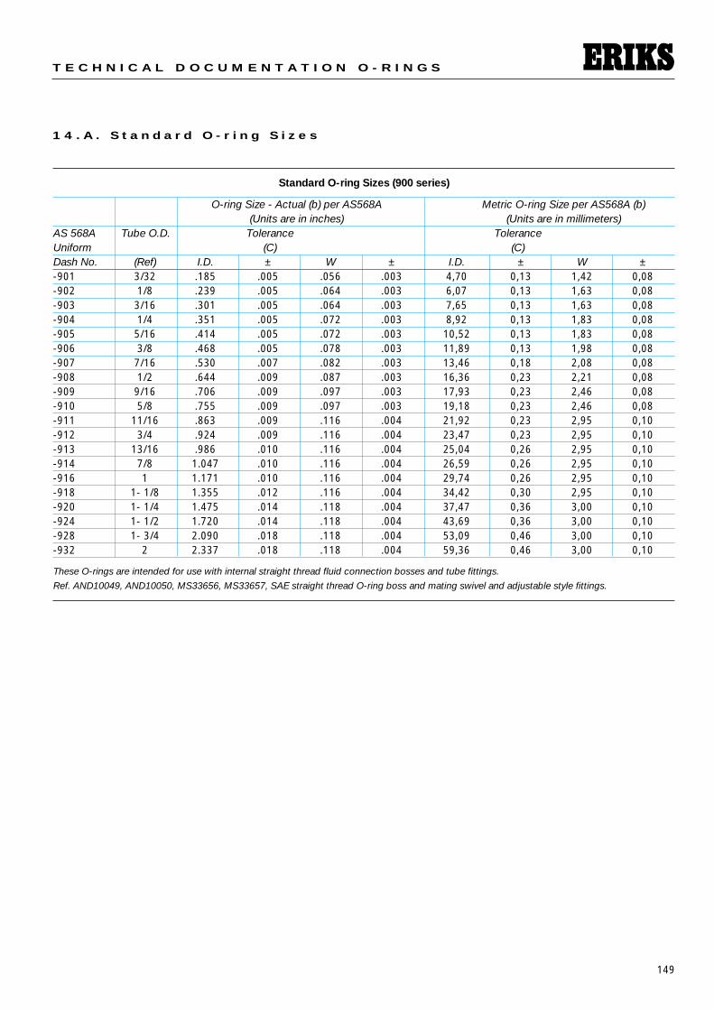
1 4 . A . S t a n d a r d O - r i n g S i z e s
Standard O-ring Sizes (900 series)
O-ring Size - Actual (b) per AS568A Metric O-ring Size per AS568A (b)(Units are in inches) (Units are in millimeters)
AS 568A Tube O.D. Tolerance ToleranceUniform (C) (C)Dash No. (Ref) I.D. ± W ± I.D. ± W ±-901 3/32 .185 .005 .056 .003 4,70 0,13 1,42 0,08-902 1/8 .239 .005 .064 .003 6,07 0,13 1,63 0,08-903 3/16 .301 .005 .064 .003 7,65 0,13 1,63 0,08-904 1/4 .351 .005 .072 .003 8,92 0,13 1,83 0,08-905 5/16 .414 .005 .072 .003 10,52 0,13 1,83 0,08-906 3/8 .468 .005 .078 .003 11,89 0,13 1,98 0,08-907 7/16 .530 .007 .082 .003 13,46 0,18 2,08 0,08-908 1/2 .644 .009 .087 .003 16,36 0,23 2,21 0,08-909 9/16 .706 .009 .097 .003 17,93 0,23 2,46 0,08-910 5/8 .755 .009 .097 .003 19,18 0,23 2,46 0,08-911 11/16 .863 .009 .116 .004 21,92 0,23 2,95 0,10-912 3/4 .924 .009 .116 .004 23,47 0,23 2,95 0,10-913 13/16 .986 .010 .116 .004 25,04 0,26 2,95 0,10-914 7/8 1.047 .010 .116 .004 26,59 0,26 2,95 0,10-916 1 1.171 .010 .116 .004 29,74 0,26 2,95 0,10-918 1- 1/8 1.355 .012 .116 .004 34,42 0,30 2,95 0,10-920 1- 1/4 1.475 .014 .118 .004 37,47 0,36 3,00 0,10-924 1- 1/2 1.720 .014 .118 .004 43,69 0,36 3,00 0,10-928 1- 3/4 2.090 .018 .118 .004 53,09 0,46 3,00 0,10-932 2 2.337 .018 .118 .004 59,36 0,46 3,00 0,10
These O-rings are intended for use with internal straight thread fluid connection bosses and tube fittings.
Ref. AND10049, AND10050, MS33656, MS33657, SAE straight thread O-ring boss and mating swivel and adjustable style fittings.
150
S E A L I N G E L E M E N T S
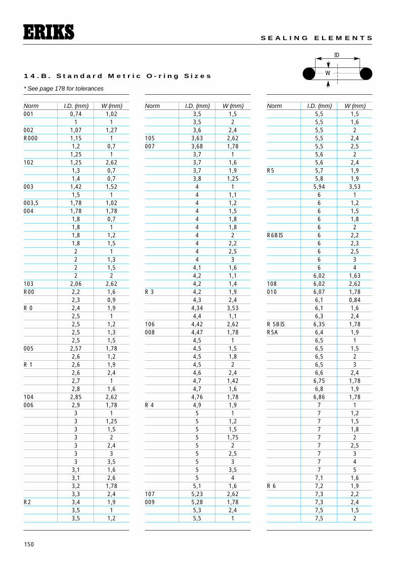
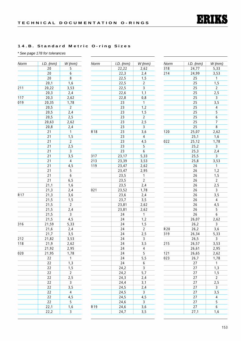
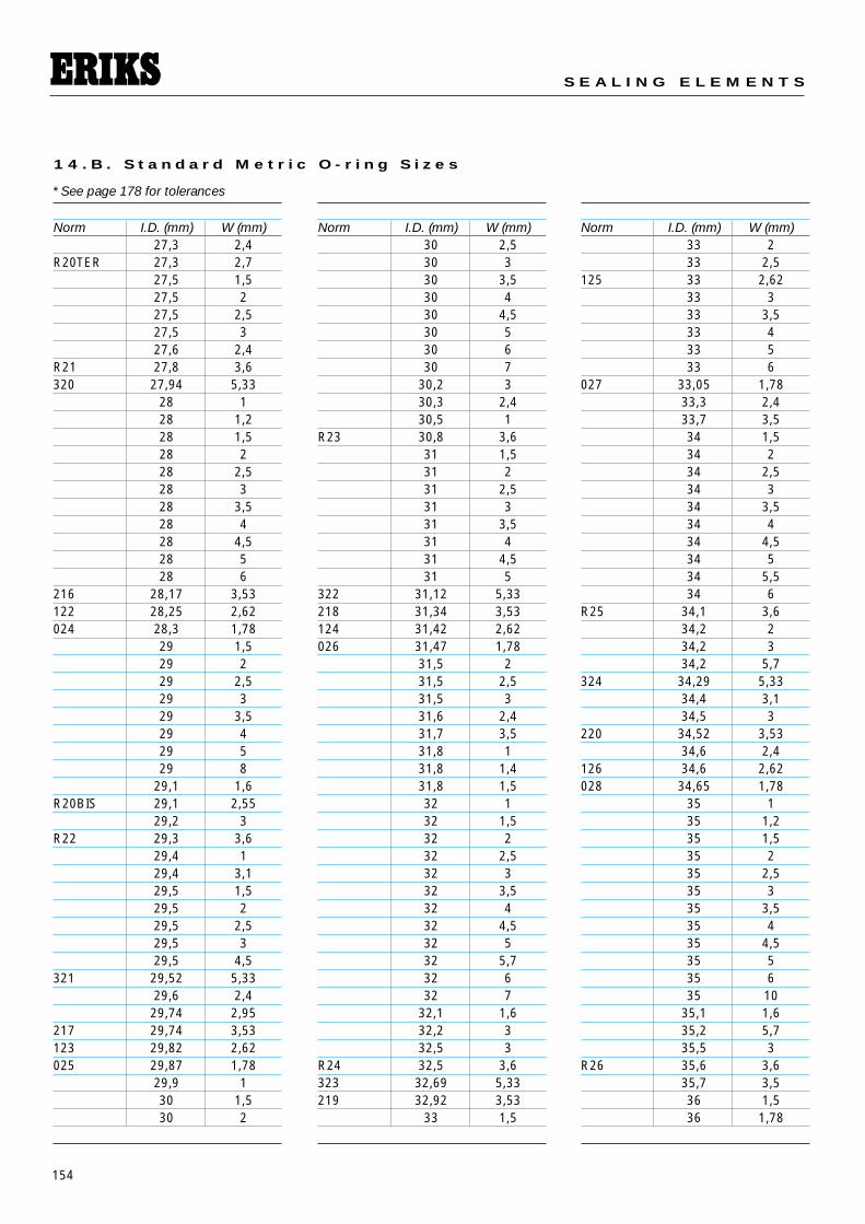
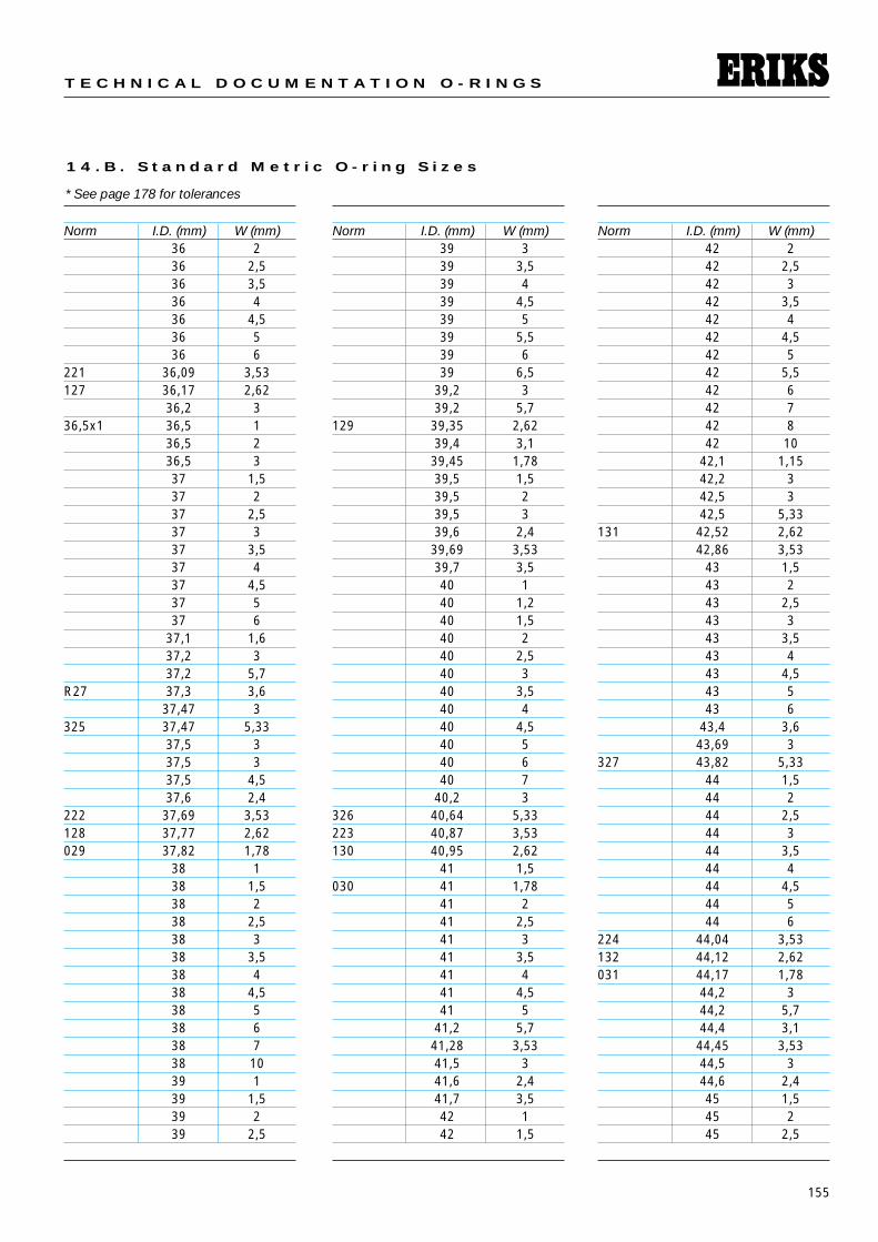
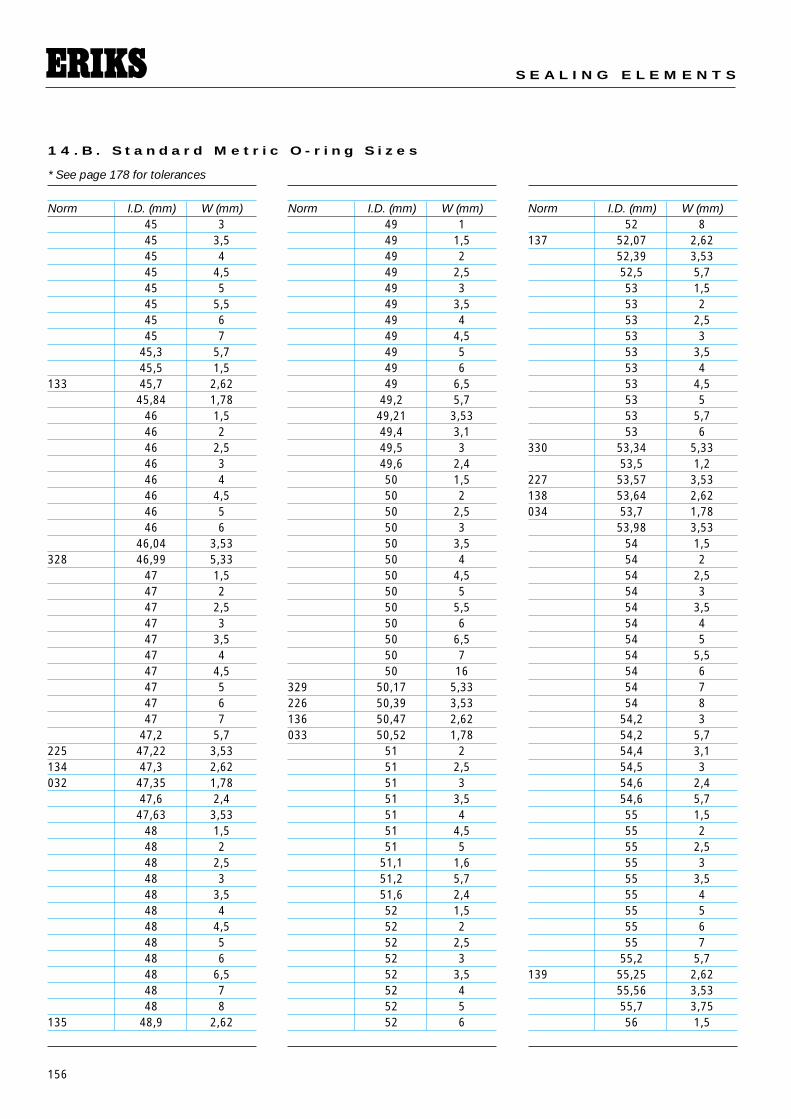
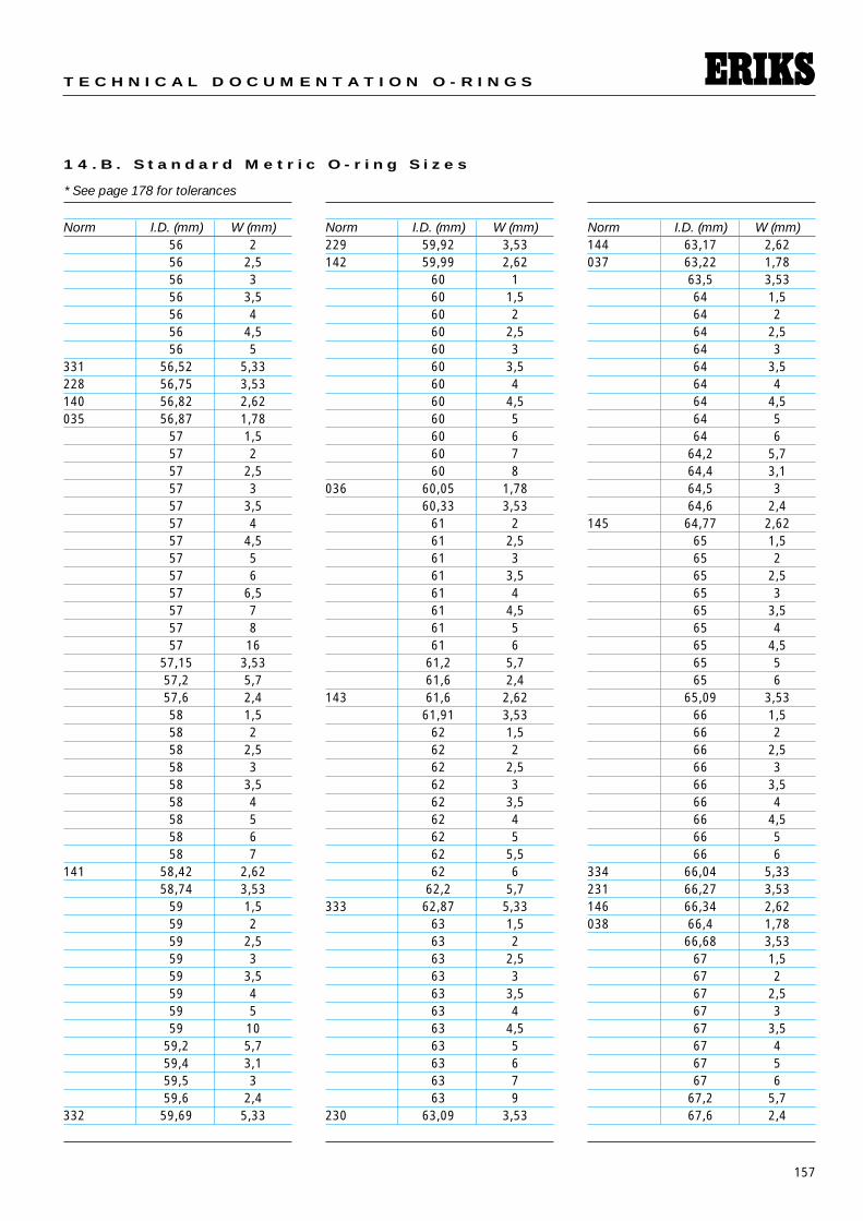
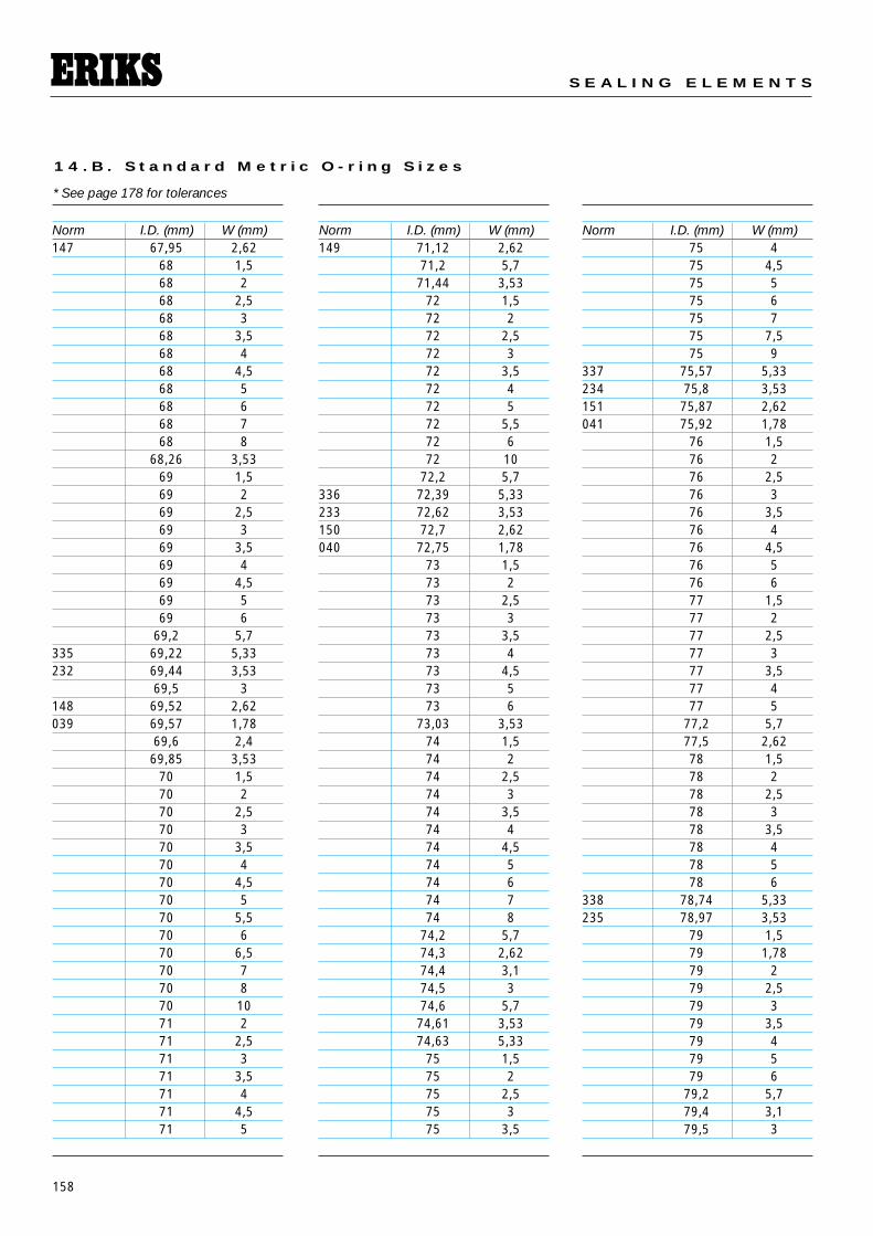
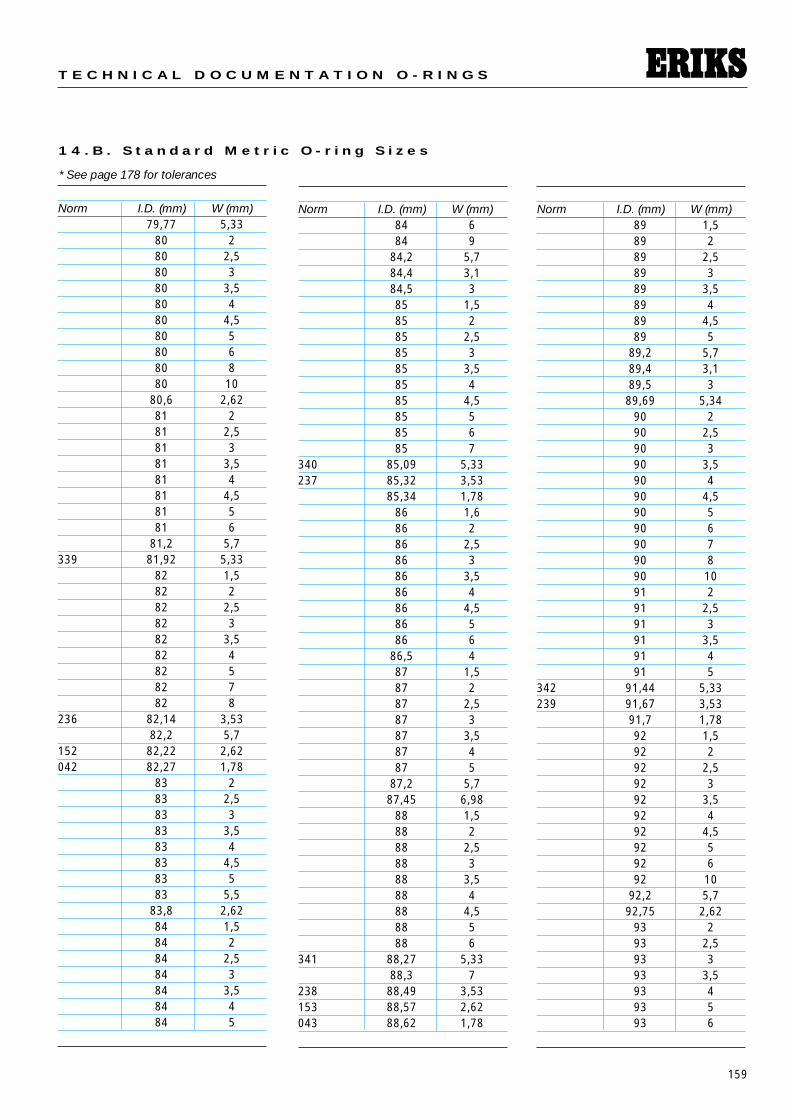
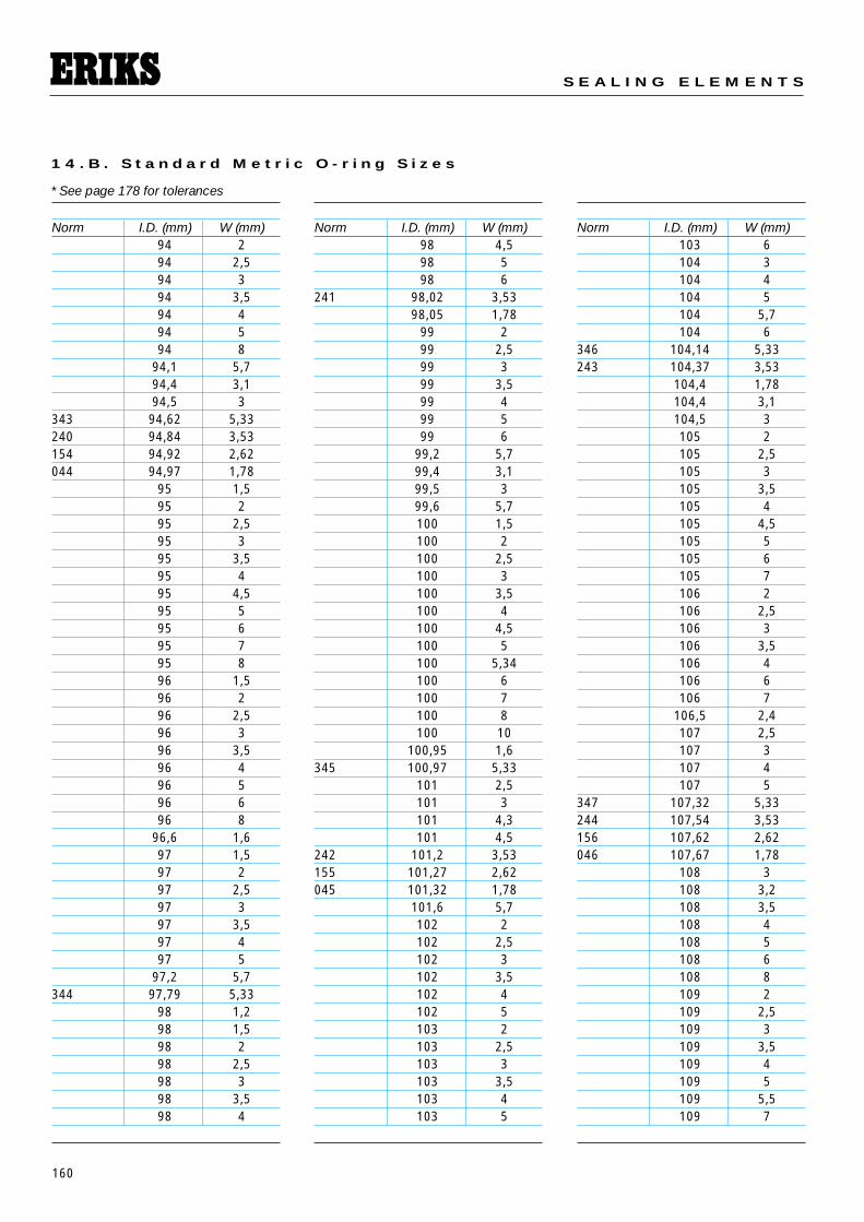
1 4 . B . S t a n d a r d M e t r i c O - r i n g S i z e s
Norm I.D. (mm) W (mm)001 0,74 1,02
1 1002 1,07 1,27R000 1,15 1
1,2 0,71,25 1
102 1,25 2,621,3 0,71,4 0,7
003 1,42 1,521,5 1
003,5 1,78 1,02004 1,78 1,78
1,8 0,71,8 11,8 1,21,8 1,52 12 1,32 1,52 2
103 2,06 2,62R00 2,2 1,6
2,3 0,9R 0 2,4 1,9
2,5 12,5 1,22,5 1,32,5 1,5
005 2,57 1,782,6 1,2
R 1 2,6 1,92,6 2,42,7 12,8 1,6
104 2,85 2,62006 2,9 1,78
3 13 1,253 1,53 23 2,43 33 3,5
3,1 1,63,1 2,63,2 1,783,3 2,4
R2 3,4 1,93,5 13,5 1,2
Norm I.D. (mm) W (mm)3,5 1,53,5 23,6 2,4
105 3,63 2,62007 3,68 1,78
3,7 13,7 1,63,7 1,93,8 1,254 14 1,14 1,24 1,54 1,84 1,84 24 2,24 2,54 3
4,1 1,64,2 1,14,2 1,4
R 3 4,2 1,94,3 2,44,34 3,534,4 1,1
106 4,42 2,62008 4,47 1,78
4,5 14,5 1,54,5 1,84,5 24,6 2,44,7 1,424,7 1,64,76 1,78
R 4 4,9 1,95 15 1,25 1,55 1,755 25 2,55 35 3,55 4
5,1 1,6107 5,23 2,62009 5,28 1,78
5,3 2,45,5 1
Norm I.D. (mm) W (mm)5,5 1,55,5 1,65,5 25,5 2,45,5 2,55,6 25,6 2,4
R5 5,7 1,95,8 1,95,94 3,53
6 16 1,26 1,56 1,86 2
R6BIS 6 2,26 2,36 2,56 36 4
6,02 1,63108 6,02 2,62010 6,07 1,78
6,1 0,846,1 1,66,3 2,4
R 5BIS 6,35 1,78R5A 6,4 1,9
6,5 16,5 1,56,5 26,5 36,6 2,46,75 1,786,8 1,96,86 1,78
7 17 1,27 1,57 1,87 27 2,57 37 47 5
7,1 1,6R 6 7,2 1,9
7,3 2,27,3 2,47,5 1,57,5 2
ID
W
* See page 178 for tolerances
151
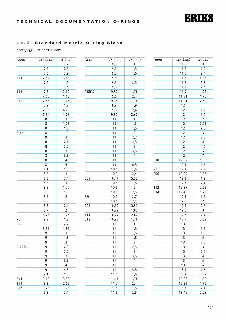
T E C H N I C A L D O C U M E N T A T I O N O - R I N G S
1 4 . B . S t a n d a r d M e t r i c O - r i n g S i z e s
Norm I.D. (mm) W (mm)7,5 2,27,5 2,57,5 3,2
203 7,52 3,537,6 1,27,6 2,4
109 7,6 2,627,65 1,63
011 7,65 1,787,8 1,97,93 4,767,94 1,78
8 18 1,258 1,5
R 6A 8 1,98 28 2,48 2,58 38 3,58 48 5
8,1 1,68,3 18,3 2,48,5 18,5 1,278,5 1,58,5 28,5 2,58,6 2,48,7 28,73 1,78
R7 8,9 1,9R8 8,9 2,7
8,92 1,839 19 1,59 2
R 7BIS 9 2,29 2,59 39 3,59 49 4,5
9,1 1,6204 9,12 3,53110 9,2 2,62012 9,25 1,78
9,3 2,4
Norm I.D. (mm) W (mm)9,5 19,5 1,59,5 1,69,5 29,5 2,59,5 3
R8BIS 9,52 1,789,6 2,49,75 1,789,8 1,99,8 2,49,92 2,6210 110 1,310 1,510 210 2,210 2,510 310 3,510 410 510 6,5
10,1 1,610,3 2,4
309 10,47 5,3310,5 1,510,5 210,5 2,5
R9 10,5 2,710,6 2,4
205 10,69 3,5310,72 1,83
111 10,77 2,62013 10,82 1,78
11 111 1,311 1,511 1,811 211 2,511 311 3,511 411 511 5,5
11,1 1,611,11 1,7811,3 2,411,5 1,511,5 2,5
Norm I.D. (mm) W (mm)11,5 311,6 1,211,6 2,411,6 6,3511,7 5,811,8 2,411,9 1,9811,91 1,7811,91 2,62
12 112 1,212 1,512 212 2,2512 2,512 312 3,512 412 4,512 512 7
310 12,07 5,3312,1 1,6
R10 12,1 2,7206 12,29 3,53
12,3 1,912,3 2,4
112 12,37 2,62014 12,42 1,78
12,5 1,512,5 212,5 2,512,5 312,6 2,412,7 2,6213 113 1,313 1,513 213 2,513 313 3,513 413 513 6
13,1 1,613,1 2,6213,26 1,5213,29 1,7813,3 2,413,46 2,08
* See page 178 for tolerances
152
S E A L I N G E L E M E N T S
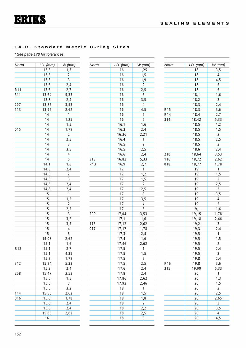
1 4 . B . S t a n d a r d M e t r i c O - r i n g S i z e s
Norm I.D. (mm) W (mm)13,5 1,313,5 213,5 313,6 2,4
R11 13,6 2,7311 13,64 5,33
13,8 2,4207 13,87 3,53113 13,95 2,62
14 114 1,2514 1,5
015 14 1,7814 214 2,514 314 3,514 414 5
14,1 1,614,3 2,414,5 214,5 314,6 2,414,8 2,415 115 1,515 215 2,515 315 3,215 3,515 415 5
15,08 2,6215,1 1,6
R12 15,1 2,715,1 4,3515,2 1,78
312 15,24 5,3315,3 2,4
208 15,47 3,5315,5 1,515,5 315,5 3,2
114 15,55 2,62016 15,6 1,78
15,6 2,415,8 2,415,88 2,62
16 1
Norm I.D. (mm) W (mm)16 1,2516 1,516 1,916 216 2,516 316 3,516 416 4,516 516 6
16,1 1,616,3 2,416,36 2,2116,4 116,5 216,5 2,516,6 2,4
313 16,82 5,33R13 16,9 2,7
17 117 1,217 1,517 217 2,517 317 3,517 417 5
209 17,04 3,5317,1 1,6
115 17,12 2,62017 17,17 1,78
17,3 2,417,4 1,617,46 2,6217,5 117,5 1,517,5 217,5 2,517,6 2,417,8 2,417,86 2,6217,93 2,46
18 118 1,518 1,818 218 2,218 2,518 3
Norm I.D. (mm) W (mm)18 3,518 418 4,518 518 6
18,1 1,618,2 318,3 2,4
R15 18,3 3,6R14 18,4 2,7314 18,42 5,33
18,5 1,218,5 1,518,5 218,5 2,518,5 318,6 2,4
210 18,64 3,53116 18,72 2,62018 18,77 1,78
19 119 1,519 219 2,519 319 3,519 419 5
19,1 1,619,15 1,7819,18 2,4619,2 319,3 2,419,5 119,5 1,519,5 219,5 2,419,5 319,8 2,4
R16 19,8 3,6315 19,99 5,33
20 120 1,320 1,520 220 2,520 2,6520 320 3,520 420 4,5
* See page 178 for tolerances
153
T E C H N I C A L D O C U M E N T A T I O N O - R I N G S
1 4 . B . S t a n d a r d M e t r i c O - r i n g S i z e s
Norm I.D. (mm) W (mm)20 520 620 8
20,1 1,6211 20,22 3,53
20,3 2,4117 20,3 2,62019 20,35 1,78
20,5 220,5 2,420,5 2,520,63 2,6220,8 2,421 121 1,521 221 2,521 321 3,521 421 4,521 521 621 6,5
21,1 1,621,3 2,4
R17 21,3 3,621,5 1,521,5 221,5 2,421,5 321,5 4,5
316 21,59 5,3321,6 2,421,7 3,5
212 21,82 3,53118 21,9 2,62
21,92 2,95020 21,95 1,78
22 122 1,322 1,522 222 2,522 322 3,522 422 4,522 5
22,1 1,622,2 3
Norm I.D. (mm) W (mm)22,22 2,6222,3 2,422,5 1,522,5 222,5 322,6 1,122,8 0,823 123 1,223 1,523 223 2,523 3
R18 23 3,623 423 4,523 523 6
317 23,17 5,33213 23,39 3,53119 23,47 2,62
23,47 2,9523,5 123,5 223,5 2,4
021 23,52 1,7823,6 2,423,7 3,523,81 2,6223,81 2,62
24 124 1,224 1,524 224 2,524 324 3,524 424 524 5,524 6
24,2 324,2 5,724,3 2,424,4 3,124,5 2,424,5 324,5 4,524,6 3
R19 24,6 3,624,7 3,5
Norm I.D. (mm) W (mm)318 24,77 5,33214 24,99 3,53
25 125 1,525 225 2,525 325 3,525 425 525 625 725 8
120 25,07 2,6225,1 1,6
022 25,12 1,7825,2 325,3 2,425,5 325,8 3,5326 126 1,226 1,526 226 2,526 326 3,526 426 4,526 526 6
26,07 2,6226,2 3
R20 26,2 3,6319 26,34 5,33
26,5 3215 26,57 3,53
26,61 2,95121 26,65 2,62023 26,7 1,78
27 127 1,327 1,527 227 2,527 327 3,527 427 527 6
27,1 1,6
* See page 178 for tolerances
154
S E A L I N G E L E M E N T S
1 4 . B . S t a n d a r d M e t r i c O - r i n g S i z e s
Norm I.D. (mm) W (mm)27,3 2,4
R20TER 27,3 2,727,5 1,527,5 227,5 2,527,5 327,6 2,4
R21 27,8 3,6320 27,94 5,33
28 128 1,228 1,528 228 2,528 328 3,528 428 4,528 528 6
216 28,17 3,53122 28,25 2,62024 28,3 1,78
29 1,529 229 2,529 329 3,529 429 529 8
29,1 1,6R20BIS 29,1 2,55
29,2 3R22 29,3 3,6
29,4 129,4 3,129,5 1,529,5 229,5 2,529,5 329,5 4,5
321 29,52 5,3329,6 2,429,74 2,95
217 29,74 3,53123 29,82 2,62025 29,87 1,78
29,9 130 1,530 2
Norm I.D. (mm) W (mm)30 2,530 330 3,530 430 4,530 530 630 7
30,2 330,3 2,430,5 1
R23 30,8 3,631 1,531 231 2,531 331 3,531 431 4,531 5
322 31,12 5,33218 31,34 3,53124 31,42 2,62026 31,47 1,78
31,5 231,5 2,531,5 331,6 2,431,7 3,531,8 131,8 1,431,8 1,532 132 1,532 232 2,532 332 3,532 432 4,532 532 5,732 632 7
32,1 1,632,2 332,5 3
R24 32,5 3,6323 32,69 5,33219 32,92 3,53
33 1,5
Norm I.D. (mm) W (mm)33 233 2,5
125 33 2,6233 333 3,533 433 533 6
027 33,05 1,7833,3 2,433,7 3,534 1,534 234 2,534 334 3,534 434 4,534 534 5,534 6
R25 34,1 3,634,2 234,2 334,2 5,7
324 34,29 5,3334,4 3,134,5 3
220 34,52 3,5334,6 2,4
126 34,6 2,62028 34,65 1,78
35 135 1,235 1,535 235 2,535 335 3,535 435 4,535 535 635 10
35,1 1,635,2 5,735,5 3
R26 35,6 3,635,7 3,536 1,536 1,78
* See page 178 for tolerances
155
T E C H N I C A L D O C U M E N T A T I O N O - R I N G S
1 4 . B . S t a n d a r d M e t r i c O - r i n g S i z e s
Norm I.D. (mm) W (mm)36 236 2,536 3,536 436 4,536 536 6
221 36,09 3,53127 36,17 2,62
36,2 336,5x1 36,5 1
36,5 236,5 337 1,537 237 2,537 337 3,537 437 4,537 537 6
37,1 1,637,2 337,2 5,7
R27 37,3 3,637,47 3
325 37,47 5,3337,5 337,5 337,5 4,537,6 2,4
222 37,69 3,53128 37,77 2,62029 37,82 1,78
38 138 1,538 238 2,538 338 3,538 438 4,538 538 638 738 1039 139 1,539 239 2,5
Norm I.D. (mm) W (mm)39 339 3,539 439 4,539 539 5,539 639 6,5
39,2 339,2 5,7
129 39,35 2,6239,4 3,139,45 1,7839,5 1,539,5 239,5 339,6 2,439,69 3,5339,7 3,540 140 1,240 1,540 240 2,540 340 3,540 440 4,540 540 640 7
40,2 3326 40,64 5,33223 40,87 3,53130 40,95 2,62
41 1,5030 41 1,78
41 241 2,541 341 3,541 441 4,541 5
41,2 5,741,28 3,5341,5 341,6 2,441,7 3,542 142 1,5
Norm I.D. (mm) W (mm)42 242 2,542 342 3,542 442 4,542 542 5,542 642 742 842 10
42,1 1,1542,2 342,5 342,5 5,33
131 42,52 2,6242,86 3,53
43 1,543 243 2,543 343 3,543 443 4,543 543 6
43,4 3,643,69 3
327 43,82 5,3344 1,544 244 2,544 344 3,544 444 4,544 544 6
224 44,04 3,53132 44,12 2,62031 44,17 1,78
44,2 344,2 5,744,4 3,144,45 3,5344,5 344,6 2,445 1,545 245 2,5
* See page 178 for tolerances
156
S E A L I N G E L E M E N T S
1 4 . B . S t a n d a r d M e t r i c O - r i n g S i z e s
Norm I.D. (mm) W (mm)45 345 3,545 445 4,545 545 5,545 645 7
45,3 5,745,5 1,5
133 45,7 2,6245,84 1,78
46 1,546 246 2,546 346 446 4,546 546 6
46,04 3,53328 46,99 5,33
47 1,547 247 2,547 347 3,547 447 4,547 547 647 7
47,2 5,7225 47,22 3,53134 47,3 2,62032 47,35 1,78
47,6 2,447,63 3,53
48 1,548 248 2,548 348 3,548 448 4,548 548 648 6,548 748 8
135 48,9 2,62
Norm I.D. (mm) W (mm)49 149 1,549 249 2,549 349 3,549 449 4,549 549 649 6,5
49,2 5,749,21 3,5349,4 3,149,5 349,6 2,450 1,550 250 2,550 350 3,550 450 4,550 550 5,550 650 6,550 750 16
329 50,17 5,33226 50,39 3,53136 50,47 2,62033 50,52 1,78
51 251 2,551 351 3,551 451 4,551 5
51,1 1,651,2 5,751,6 2,452 1,552 252 2,552 352 3,552 452 552 6
Norm I.D. (mm) W (mm)52 8
137 52,07 2,6252,39 3,5352,5 5,753 1,553 253 2,553 353 3,553 453 4,553 553 5,753 6
330 53,34 5,3353,5 1,2
227 53,57 3,53138 53,64 2,62034 53,7 1,78
53,98 3,5354 1,554 254 2,554 354 3,554 454 554 5,554 654 754 8
54,2 354,2 5,754,4 3,154,5 354,6 2,454,6 5,755 1,555 255 2,555 355 3,555 455 555 655 7
55,2 5,7139 55,25 2,62
55,56 3,5355,7 3,7556 1,5
* See page 178 for tolerances
157
T E C H N I C A L D O C U M E N T A T I O N O - R I N G S
1 4 . B . S t a n d a r d M e t r i c O - r i n g S i z e s
Norm I.D. (mm) W (mm)56 256 2,556 356 3,556 456 4,556 5
331 56,52 5,33228 56,75 3,53140 56,82 2,62035 56,87 1,78
57 1,557 257 2,557 357 3,557 457 4,557 557 657 6,557 757 857 16
57,15 3,5357,2 5,757,6 2,458 1,558 258 2,558 358 3,558 458 558 658 7
141 58,42 2,6258,74 3,53
59 1,559 259 2,559 359 3,559 459 559 10
59,2 5,759,4 3,159,5 359,6 2,4
332 59,69 5,33
Norm I.D. (mm) W (mm)229 59,92 3,53142 59,99 2,62
60 160 1,560 260 2,560 360 3,560 460 4,560 560 660 760 8
036 60,05 1,7860,33 3,53
61 261 2,561 361 3,561 461 4,561 561 6
61,2 5,761,6 2,4
143 61,6 2,6261,91 3,53
62 1,562 262 2,562 362 3,562 462 562 5,562 6
62,2 5,7333 62,87 5,33
63 1,563 263 2,563 363 3,563 463 4,563 563 663 763 9
230 63,09 3,53
Norm I.D. (mm) W (mm)144 63,17 2,62037 63,22 1,78
63,5 3,5364 1,564 264 2,564 364 3,564 464 4,564 564 6
64,2 5,764,4 3,164,5 364,6 2,4
145 64,77 2,6265 1,565 265 2,565 365 3,565 465 4,565 565 6
65,09 3,5366 1,566 266 2,566 366 3,566 466 4,566 566 6
334 66,04 5,33231 66,27 3,53146 66,34 2,62038 66,4 1,78
66,68 3,5367 1,567 267 2,567 367 3,567 467 567 6
67,2 5,767,6 2,4
* See page 178 for tolerances
158
S E A L I N G E L E M E N T S
1 4 . B . S t a n d a r d M e t r i c O - r i n g S i z e s
Norm I.D. (mm) W (mm)147 67,95 2,62
68 1,568 268 2,568 368 3,568 468 4,568 568 668 768 8
68,26 3,5369 1,569 269 2,569 369 3,569 469 4,569 569 6
69,2 5,7335 69,22 5,33232 69,44 3,53
69,5 3148 69,52 2,62039 69,57 1,78
69,6 2,469,85 3,53
70 1,570 270 2,570 370 3,570 470 4,570 570 5,570 670 6,570 770 870 1071 271 2,571 371 3,571 471 4,571 5
Norm I.D. (mm) W (mm)149 71,12 2,62
71,2 5,771,44 3,53
72 1,572 272 2,572 372 3,572 472 572 5,572 672 10
72,2 5,7336 72,39 5,33233 72,62 3,53150 72,7 2,62040 72,75 1,78
73 1,573 273 2,573 373 3,573 473 4,573 573 6
73,03 3,5374 1,574 274 2,574 374 3,574 474 4,574 574 674 774 8
74,2 5,774,3 2,6274,4 3,174,5 374,6 5,774,61 3,5374,63 5,33
75 1,575 275 2,575 375 3,5
Norm I.D. (mm) W (mm)75 475 4,575 575 675 775 7,575 9
337 75,57 5,33234 75,8 3,53151 75,87 2,62041 75,92 1,78
76 1,576 276 2,576 376 3,576 476 4,576 576 677 1,577 277 2,577 377 3,577 477 5
77,2 5,777,5 2,6278 1,578 278 2,578 378 3,578 478 578 6
338 78,74 5,33235 78,97 3,53
79 1,579 1,7879 279 2,579 379 3,579 479 579 6
79,2 5,779,4 3,179,5 3
* See page 178 for tolerances
159
T E C H N I C A L D O C U M E N T A T I O N O - R I N G S
1 4 . B . S t a n d a r d M e t r i c O - r i n g S i z e s
Norm I.D. (mm) W (mm)79,77 5,33
80 280 2,580 380 3,580 480 4,580 580 680 880 10
80,6 2,6281 281 2,581 381 3,581 481 4,581 581 6
81,2 5,7339 81,92 5,33
82 1,582 282 2,582 382 3,582 482 582 782 8
236 82,14 3,5382,2 5,7
152 82,22 2,62042 82,27 1,78
83 283 2,583 383 3,583 483 4,583 583 5,5
83,8 2,6284 1,584 284 2,584 384 3,584 484 5
Norm I.D. (mm) W (mm)84 684 9
84,2 5,784,4 3,184,5 385 1,585 285 2,585 385 3,585 485 4,585 585 685 7
340 85,09 5,33237 85,32 3,53
85,34 1,7886 1,686 286 2,586 386 3,586 486 4,586 586 6
86,5 487 1,587 287 2,587 387 3,587 487 5
87,2 5,787,45 6,98
88 1,588 288 2,588 388 3,588 488 4,588 588 6
341 88,27 5,3388,3 7
238 88,49 3,53153 88,57 2,62043 88,62 1,78
Norm I.D. (mm) W (mm)89 1,589 289 2,589 389 3,589 489 4,589 5
89,2 5,789,4 3,189,5 389,69 5,34
90 290 2,590 390 3,590 490 4,590 590 690 790 890 1091 291 2,591 391 3,591 491 5
342 91,44 5,33239 91,67 3,53
91,7 1,7892 1,592 292 2,592 392 3,592 492 4,592 592 692 10
92,2 5,792,75 2,62
93 293 2,593 393 3,593 493 593 6
* See page 178 for tolerances
160
S E A L I N G E L E M E N T S
1 4 . B . S t a n d a r d M e t r i c O - r i n g S i z e s
Norm I.D. (mm) W (mm)94 294 2,594 394 3,594 494 594 8
94,1 5,794,4 3,194,5 3
343 94,62 5,33240 94,84 3,53154 94,92 2,62044 94,97 1,78
95 1,595 295 2,595 395 3,595 495 4,595 595 695 795 896 1,596 296 2,596 396 3,596 496 596 696 8
96,6 1,697 1,597 297 2,597 397 3,597 497 5
97,2 5,7344 97,79 5,33
98 1,298 1,598 298 2,598 398 3,598 4
Norm I.D. (mm) W (mm)98 4,598 598 6
241 98,02 3,5398,05 1,78
99 299 2,599 399 3,599 499 599 6
99,2 5,799,4 3,199,5 399,6 5,7100 1,5100 2100 2,5100 3100 3,5100 4100 4,5100 5100 5,34100 6100 7100 8100 10
100,95 1,6345 100,97 5,33
101 2,5101 3101 4,3101 4,5
242 101,2 3,53155 101,27 2,62045 101,32 1,78
101,6 5,7102 2102 2,5102 3102 3,5102 4102 5103 2103 2,5103 3103 3,5103 4103 5
Norm I.D. (mm) W (mm)103 6104 3104 4104 5104 5,7104 6
346 104,14 5,33243 104,37 3,53
104,4 1,78104,4 3,1104,5 3105 2105 2,5105 3105 3,5105 4105 4,5105 5105 6105 7106 2106 2,5106 3106 3,5106 4106 6106 7
106,5 2,4107 2,5107 3107 4107 5
347 107,32 5,33244 107,54 3,53156 107,62 2,62046 107,67 1,78
108 3108 3,2108 3,5108 4108 5108 6108 8109 2109 2,5109 3109 3,5109 4109 5109 5,5109 7
* See page 178 for tolerances
161
T E C H N I C A L D O C U M E N T A T I O N O - R I N G S
1 4 . B . S t a n d a r d M e t r i c O - r i n g S i z e s
Norm I.D. (mm) W (mm)109,2 5,7109,4 3,1109,5 3109,5 5,33109,5 5,5110 2110 2,5110 3110 3,5110 4110 4,5110 5110 6110 7110 11
348 110,49 5,33245 110,72 3,53
110,74 1,78111 3111 5111 6112 2112 2,5112 3112 4112 5112 6113 2,5113 3113 3,5113 4113 5
349 113,67 5,33425 113,67 7246 113,89 3,53157 113,97 2,62
114 2,5114 3114 4114 5114 5,5114 6114 8114 9
047 114,02 1,78114,3 5,7114,4 3,1114,5 3114,7 7115 1115 1,6
Norm I.D. (mm) W (mm)115 2115 2,5115 3115 4115 4,5115 5115 6116 2,5116 3116 4
350 116,84 5,33426 116,84 7
117 2,5117 2,7117 3117 4117 5
247 117,07 3,53117,1 1,78117,5 5,34118 3118 4118 5118 6119 3119 4119 5
119,2 5,7119,4 3,1119,5 3120 2120 3120 3,5120 4120 5120 6120 10
351 120,02 5,33427 120,02 7248 120,25 3,53158 120,32 2,62048 120,37 1,78
121 4121 5
121,5 2,2122 2,5122 3122 3,5122 4122 5122 6
Norm I.D. (mm) W (mm)123 3123 4123 5123 6123 6,3
352 123,19 5,33428 123,19 7249 123,42 3,53
123,44 1,78124 3124 3,25124 4124 5124 6124 18
124,3 5,7124,4 3,1124,5 3125 2,4125 2,5125 3125 3,5125 4125 5125 6125 8,3
125,6 2126 3126 4126 5126 6
353 126,37 5,33429 126,37 7250 126,6 3,53159 126,67 2,62049 126,72 1,78
127 3127 4127 5128 2128 3128 4128 5128 6129 2,5129 3129 4129 5
129,2 5,7129,4 1,78129,4 3,1
* See page 178 for tolerances
162
S E A L I N G E L E M E N T S
1 4 . B . S t a n d a r d M e t r i c O - r i n g S i z e s
Norm I.D. (mm) W (mm)129,5 3
354 129,54 5,33430 129,54 7251 129,77 3,53
130 2130 2,5130 3130 4130 5130 6130 8
130,2 5,34130,5 3131 2,5131 3131 4131 5
131,2 5,7132 3132 4132 5132 6132 8
355 132,72 5,33431 132,72 7252 132,95 3,53
133 3133 4133 5
160 133,02 2,62050 133,07 1,78
134 3134 4134 5134 6
134,3 5,7134,4 3,1134,5 3134,5 6,99135 2,5135 3135 4135 5135 6135 10
135,76 1,78356 135,89 5,33432 135,89 7
136 3136 4136 5
Norm I.D. (mm) W (mm)136 6
253 136,12 3,53137 3137 4137 5138 2,1138 3138 3,5138 4138 5138 6
138,94 1,78139 3139 4139 5
357 139,07 5,33433 139,07 7254 139,3 3,53
139,3 5,7161 139,37 2,62
139,4 3,1139,5 3139,7 5,34140 2140 2,5140 3140 4140 5140 6140 8140 10141 3141 4141 5142 3142 4142 5142 6
142,11 1,78358 142,24 5,33434 142,24 7255 142,47 3,53
143 3143 4143 5144 3144 4144 5
144,1 8,4144,3 5,7144,4 3,1
Norm I.D. (mm) W (mm)144,5 3144,6 5,7145 2145 2,5145 3,5145 4145 5145 5,5
145,29 1,78359 145,42 5,33435 145,42 7256 145,64 3,53162 145,72 2,62
146 3146 4146 5146 6
146,04 5,33147 3147 4147 5148 3148 4148 5148 6148 8
148,46 1,78360 148,59 5,33436 148,59 7257 148,82 3,53
149 3149 4149 5
149,1 8,4149,2 5,33149,2 5,7149,5 3149,6 5,7150 2150 2,5150 3150 3,5150 4150 5150 6150 8
151,46 1,78361 151,77 5,33437 151,77 7
152 3258 152 3,53
* See page 178 for tolerances
163
T E C H N I C A L D O C U M E N T A T I O N O - R I N G S
1 4 . B . S t a n d a r d M e t r i c O - r i n g S i z e s
Norm I.D. (mm) W (mm)152 4152 5
163 152,07 2,62153 4,5153 5153 6154 3154 4154 5154 6
154,1 8,4154,3 5,7154,5 3154,8 5,7155 3155 4155 5155 5,33155 6
155,6 7156 3156 4156 5156 6157 3157 4157 4,5157 5157 6158 1,78158 3158 4158 5158 6
362 158,12 5,33438 158,12 7259 158,34 3,53164 158,42 2,62
159,1 8,4159,3 5,7159,5 3159,5 7159,8 5,7160 2160 3160 3,5160 4160 5160 6160 8160 10
Norm I.D. (mm) W (mm)161,3 5,33161,6 2,4161,9 7162 3162 4162 5162 6
164,1 8,4164,2 5,7
363 164,47 5,33439 164,47 7
164,5 3260 164,7 3,53165 164,77 2,62
164,8 5,7165 2165 3165 4165 5165 6165 7
166,7 7167 3
167,7 5,33168 3168 4168 5168 5,7
168,3 7169 4169 5
169,1 8,4169,3 5,7169,5 3169,8 5,7170 2170 3170 4170 5170 6
364 170,82 5,33440 170,82 7261 171,04 3,53166 171,12 2,62
172 3172 4172 5172 6174 3174 3,2174 4
Norm I.D. (mm) W (mm)174 5174 6
174,1 8,4174,2 5,7174,5 3174,6 7174,8 5,7175 2,5175 3175 4175 5175 6
365 177,17 5,33441 177,17 7262 177,4 3,53167 177,47 2,62
178 3178 4178 5178 6178 10179 3
179,1 8,4179,3 5,7179,5 3179,8 5,7180 2180 3180 4180 5180 6180 8181 7182 3182 4182 5182 6
183,5 3366 183,52 5,33442 183,52 7263 183,74 3,53168 183,82 2,62
184 4184 5184 6
184,1 8,4184,3 5,7184,5 3184,8 5,7185 3185 4
* See page 178 for tolerances
164
S E A L I N G E L E M E N T S
1 4 . B . S t a n d a r d M e t r i c O - r i n g S i z e s
Norm I.D. (mm) W (mm)185 5185 6186 3186 3186 4
187,3 7188 3188 4188 5188 6
189,1 8,4189,2 5,7189,5 3189,8 5,7
367 189,87 5,33443 189,87 7
190 3190 4190 5190 6
264 190,1 3,53169 190,17 2,62
192 3192 4192 5192 7
193,3 4194 2194 4194 6,1
194,1 8,4194,3 5,7194,5 3195 3,5195 4195 5195 6195 6,75195 8195 10
368 196,22 5,33444 196,22 7265 196,44 3,53170 196,52 2,62
197 3198 4198 5198 6
199,1 8,4199,2 5,7199,5 3
Norm I.D. (mm) W (mm)199,8 5,7200 2200 3200 4200 5200 6200 7200 8200 15202 5202 5,5202 6
369 202,57 5,33445 202,57 7266 202,8 3,53171 202,87 2,62
203 3203 4203 4203 5203 6204 6
204,2 5,7205 2205 3205 4205 4,5205 5205 6205 9205 10206 6208 3208 4208 5208 6
208,9 7370 208,92 5,33
209,1 8,4267 209,14 3,53172 209,22 2,62
209,3 5,7209,5 3210 2210 3210 4210 5210 6210 8212 3212 4
Norm I.D. (mm) W (mm)212 5212 6212 6,3212 7
214,3 5,7215 3215 4215 5215 6
371 215,27 5,33446 215,27 7268 215,5 3,53173 215,57 2,62
216 8217 5218 3218 4218 4,5218 5218 5,8218 6
219,1 8,4219,3 5,7219,5 3219,5 3,2220 3220 4220 5220 6220 10
221,6 6,99372 221,62 5,33269 221,84 3,53174 221,92 2,62
222 6224 3,8225 3225 4225 5225 10226 8227 3,2
373 227,97 5,33447 227,97 7
228 3228 4228 5228 10
270 228,2 3,53175 228,27 2,62
229 6
* See page 178 for tolerances
165
T E C H N I C A L D O C U M E N T A T I O N O - R I N G S
1 4 . B . S t a n d a r d M e t r i c O - r i n g S i z e s
Norm I.D. (mm) W (mm)229,1 8,4229,3 5,7229,5 3230 3230 4230 5230 6230 8232 3233 3
234,3 5,7234,3 6,99
374 234,32 5,33271 234,55 3,53176 234,62 2,62
235 3235 4235 5235 6235 8236 12238 5238 6
239,1 8,4239,3 5,7239,5 3240 3240 4240 5240 6240 8240 10
375 240,67 5,33448 240,67 7272 240,9 3,53177 240,97 2,62
242 8245 3245 3,5245 4245 5245 8246 4247 3247 5247 6247 7
376 247,02 5,33273 247,25 3,53178 247,32 2,62
248 5
Norm I.D. (mm) W (mm)249,1 8,4249,3 5,7249,5 3250 3250 4250 5250 6250 6,5250 7250 8250 10253 8
377 253,37 5,33449 253,37 7274 253,6 3,53
254 8255 3255 4255 5255 5,7258 4258 6
259,3 3259,3 5,7259,7 7260 3260 4260 5260 6260 8262 2262 4262 5264 3264 10265 4265 5265 6265 8
265,3 3378 266,07 5,33450 266,07 7275 266,29 3,53
268 4268 5
268,8 8,4269,3 5,7270 3270 4270 5270 6
Norm I.D. (mm) W (mm)270 10
272,4 6,99275 2275 3275 4275 5275 6278 4278 5278 6
379 278,77 5,33451 278,77 7276 278,99 3,53
278,99 3,83279 8
279,3 5,7280 3280 4280 5280 6280 8280 10283 3,5285 3285 4285 5285 6
285,1 7288 4288 5288 6
289,3 5,7290 2290 3290 4290 5290 6
380 291,47 5,33452 291,47 7277 291,69 3,53
292 10295 4295 5295 6297 4
297,8 7298 4298 5
299,3 5,7300 3300 4
* See page 178 for tolerances
166
S E A L I N G E L E M E N T S
1 4 . B . S t a n d a r d M e t r i c O - r i n g S i z e s
Norm I.D. (mm) W (mm)300 5300 6300 6,3300 7300 7300 9300 10
381 304,17 5,33453 304,17 7278 304,39 3,53
305 4305 5305 6305 10308 4308 5309 3
309,3 5,7310 4310 5310 6310 8310 16
310,5 7311 6312 4312 5315 3315 4315 5315 5,33315 6315 6,3315 10316 9
454 316,87 7318 4318 5
319,2 3,53319,3 5,7320 3320 3,5320 4320 5320 6320 6,5320 7320 8320 10325 4325 5
Norm I.D. (mm) W (mm)325 6325 10326 8328 10
382 329,57 5,33455 329,57 7279 329,79 3,53
330 3330 4330 5330 5,7330 6330 6,5330 8330 10335 4335 5335 6339 8,4
339,3 5,7340 4340 5340 6340 10340 16342 5
456 342,27 7344 6,99345 4345 5345 6346 10347 6
349,3 5,7350 3350 4350 5350 6350 8
383 354,97 5,33457 354,97 7
355 3355 4355 5355 6
280 355,19 3,53357 12358 6
359,3 5,7360 4360 5
Norm I.D. (mm) W (mm)360 6360 7360 7,5360 8360 9360 10363 5,33365 4365 5365 6
458 367,67 7370 4370 5370 6374 5374 8375 4375 5375 6375 7375 8,4378 4378 12
379,3 5,7380 4380 5380 6380 8380 10
384 380,37 5,33459 380,37 7281 380,59 3,53
385 3385 4385 5385 6387 20390 3,5390 4390 5390 6390 9390 16391 8392 6
460 393,07 7394 8,4395 4395 5395 6395 8
* See page 178 for tolerances
167
T E C H N I C A L D O C U M E N T A T I O N O - R I N G S
1 4 . B . S t a n d a r d M e t r i c O - r i n g S i z e s
Norm I.D. (mm) W (mm)396 12
399,3 5,7400 2400 3400 4400 5400 6400 7400 8402 4402 9
282 405,26 3,53385 405,26 5,33461 405,26 7
406 3,1410 4410 5410 6410 7410 8410 9412 8415 5415 6415 7
462 417,96 7419,1 8,4419,3 5,7420 4420 6420 8420 9420 10422 6
422,2 6,2422,2 6,9425 4425 5425 6425 7425 8426 5,7427 5429 6430 8,4
283 430,66 3,53386 430,66 5,33463 430,66 7
434 10439,3 5,7440 3
Norm I.D. (mm) W (mm)440 4440 7
464 443,36 7445 5445 9450 4450 6450 7450 8450 10451 9454 8,4455 5
284 456,06 3,53387 456,06 5,33465 456,06 7
459,3 5,7460 5460 6460 7460 8460 12461 8,4462 10462 15465 5
466 468,76 7470 4470 5470 6470 8470 10475 8475 10478 6
479,3 5,7480 4480 5480 6480 7480 8480 9480 10
388 481,38 5,33467 481,46 7
483 8,4485 5485 5,7485 8488 6489 6
Norm I.D. (mm) W (mm)490 5490 7490 8490 10490 16
491,49 5,33492 4
468 494,16 7498 14
499,3 5,7500 3,53500 5500 6500 7500 8500 9500 10502 16505 3505 4505 6505 10
389 506,78 5,33469 506,86 7
510 5515 7515 8517 5,33
518,5 3519,3 5,7520 8520 10
520,06 7525 5525 6525 8
529,3 5,7530 4530 5530 6530 7530 10
390 532,18 5,33470 532,26 7
534 16540 10541 14545 5,7545 9
ASA100 545,47 7550 5
* See page 178 for tolerances
168
S E A L I N G E L E M E N T S
1 4 . B . S t a n d a r d M e t r i c O - r i n g S i z e s
Norm I.D. (mm) W (mm)550 6550 7550 8552 4552 5,33
554,3 5,7391 557,58 5,33471 557,66 7
560 8560 10562 7,5566 6,35570 10573 7575 4577 20577 21580 8580 9580 10
392 582,68 5,33472 582,68 7
584 8,4585 16590 6590 10594 5,7595 6595 8
ASA104 596,27 7600 7600 8600 10
393 608,08 5,33473 608,08 7
610 6610 6,35614 7617 8620 5620 8620 10625 3626 7630 8
394 633,48 5,33474 633,48 7
635 8637 10638 8640 7
Norm I.D. (mm) W (mm)643 7650 7650 8650 10
395 658,88 5,33475 658,88 7
660 9660 10665 6670 7670 8674 7675 8680 7680 8680 8,4680 16685 7690 10695 8699 7700 8700 10702 20705 5,33705 7710 8,4724 7725 5,7725 9
730,5 7735 7736 5,33739 7740 8,4743 10745 7760 7763 10770 4
774,1 8,4776 7790 6,3790 10799 12800 7800 8805 20805 21810 9820 7
Norm I.D. (mm) W (mm)836 3845 10847 5,33850 7860 7870 5,33875 8876 7878 5,33880 7890 5,33890 5,7900 7920 7925 10930 8
932,5 7950 10957 7975 5,33997 71000 101011 71014 5,331029 6,351040 71045 5,331075 71089 6,991100 6,991142 71185 71245 7
Many more sizes are availableupon request in differentcompounds.
Please ask an ERIKS representative for assistance inselecting a custom product.
* See page 178 for tolerances
169
T E C H N I C A L D O C U M E N T A T I O N O - R I N G S
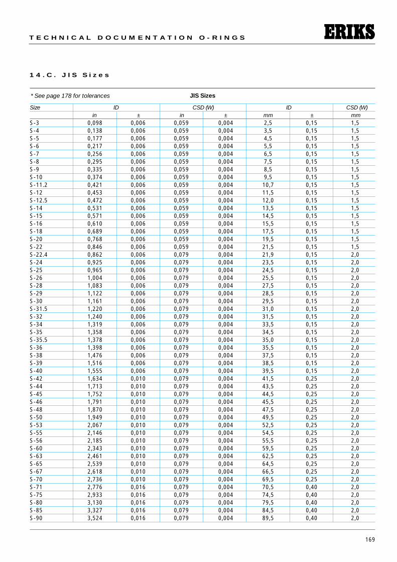
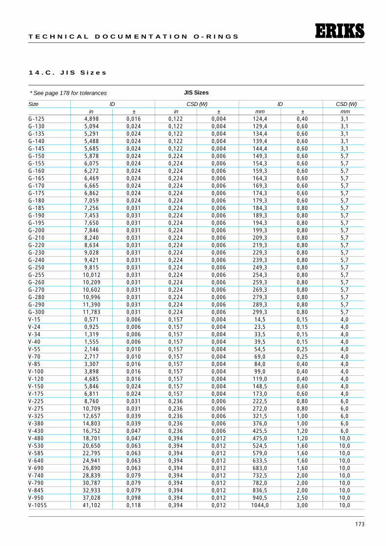
1 4 . C . J I S S i z e s
JIS Sizes
Size ID CSD (W) ID CSD (W)in ± in ± mm ± mm
S-3 0,098 0,006 0,059 0,004 2,5 0,15 1,5S-4 0,138 0,006 0,059 0,004 3,5 0,15 1,5S-5 0,177 0,006 0,059 0,004 4,5 0,15 1,5S-6 0,217 0,006 0,059 0,004 5,5 0,15 1,5S-7 0,256 0,006 0,059 0,004 6,5 0,15 1,5S-8 0,295 0,006 0,059 0,004 7,5 0,15 1,5S-9 0,335 0,006 0,059 0,004 8,5 0,15 1,5S-10 0,374 0,006 0,059 0,004 9,5 0,15 1,5S-11.2 0,421 0,006 0,059 0,004 10,7 0,15 1,5S-12 0,453 0,006 0,059 0,004 11,5 0,15 1,5S-12.5 0,472 0,006 0,059 0,004 12,0 0,15 1,5S-14 0,531 0,006 0,059 0,004 13,5 0,15 1,5S-15 0,571 0,006 0,059 0,004 14,5 0,15 1,5S-16 0,610 0,006 0,059 0,004 15,5 0,15 1,5S-18 0,689 0,006 0,059 0,004 17,5 0,15 1,5S-20 0,768 0,006 0,059 0,004 19,5 0,15 1,5S-22 0,846 0,006 0,059 0,004 21,5 0,15 1,5S-22.4 0,862 0,006 0,079 0,004 21,9 0,15 2,0S-24 0,925 0,006 0,079 0,004 23,5 0,15 2,0S-25 0,965 0,006 0,079 0,004 24,5 0,15 2,0S-26 1,004 0,006 0,079 0,004 25,5 0,15 2,0S-28 1,083 0,006 0,079 0,004 27,5 0,15 2,0S-29 1,122 0,006 0,079 0,004 28,5 0,15 2,0S-30 1,161 0,006 0,079 0,004 29,5 0,15 2,0S-31.5 1,220 0,006 0,079 0,004 31,0 0,15 2,0S-32 1,240 0,006 0,079 0,004 31,5 0,15 2,0S-34 1,319 0,006 0,079 0,004 33,5 0,15 2,0S-35 1,358 0,006 0,079 0,004 34,5 0,15 2,0S-35.5 1,378 0,006 0,079 0,004 35,0 0,15 2,0S-36 1,398 0,006 0,079 0,004 35,5 0,15 2,0S-38 1,476 0,006 0,079 0,004 37,5 0,15 2,0S-39 1,516 0,006 0,079 0,004 38,5 0,15 2,0S-40 1,555 0,006 0,079 0,004 39,5 0,15 2,0S-42 1,634 0,010 0,079 0,004 41,5 0,25 2,0S-44 1,713 0,010 0,079 0,004 43,5 0,25 2,0S-45 1,752 0,010 0,079 0,004 44,5 0,25 2,0S-46 1,791 0,010 0,079 0,004 45,5 0,25 2,0S-48 1,870 0,010 0,079 0,004 47,5 0,25 2,0S-50 1,949 0,010 0,079 0,004 49,5 0,25 2,0S-53 2,067 0,010 0,079 0,004 52,5 0,25 2,0S-55 2,146 0,010 0,079 0,004 54,5 0,25 2,0S-56 2,185 0,010 0,079 0,004 55,5 0,25 2,0S-60 2,343 0,010 0,079 0,004 59,5 0,25 2,0S-63 2,461 0,010 0,079 0,004 62,5 0,25 2,0S-65 2,539 0,010 0,079 0,004 64,5 0,25 2,0S-67 2,618 0,010 0,079 0,004 66,5 0,25 2,0S-70 2,736 0,010 0,079 0,004 69,5 0,25 2,0S-71 2,776 0,016 0,079 0,004 70,5 0,40 2,0S-75 2,933 0,016 0,079 0,004 74,5 0,40 2,0S-80 3,130 0,016 0,079 0,004 79,5 0,40 2,0S-85 3,327 0,016 0,079 0,004 84,5 0,40 2,0S-90 3,524 0,016 0,079 0,004 89,5 0,40 2,0
* See page 178 for tolerances
170
S E A L I N G E L E M E N T S
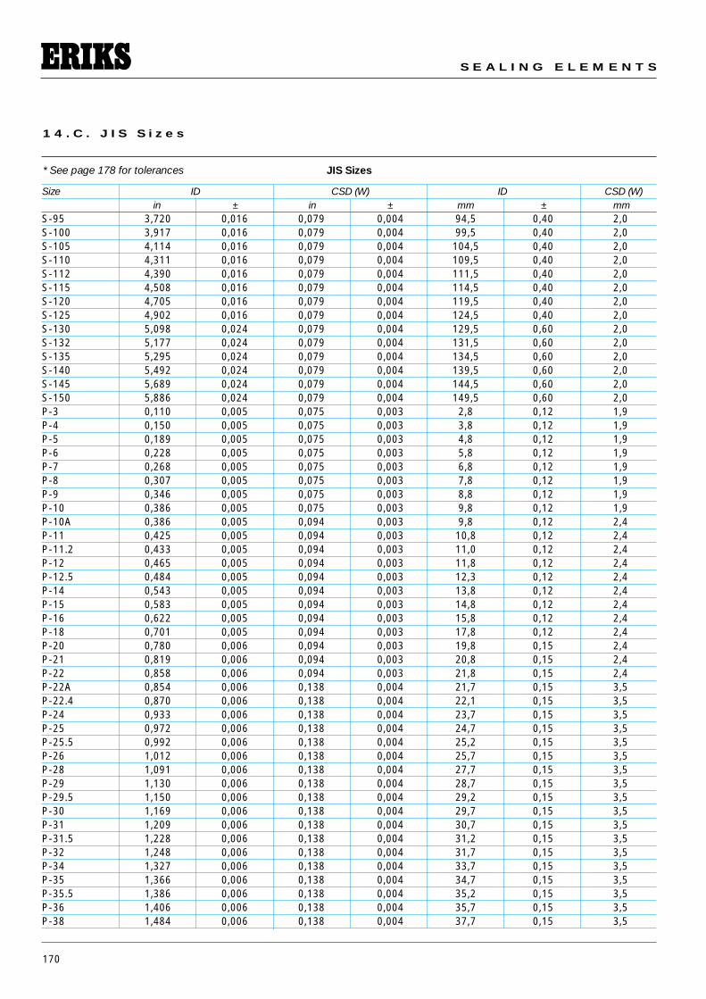
1 4 . C . J I S S i z e s
JIS Sizes
Size ID CSD (W) ID CSD (W)in ± in ± mm ± mm
S-95 3,720 0,016 0,079 0,004 94,5 0,40 2,0S-100 3,917 0,016 0,079 0,004 99,5 0,40 2,0S-105 4,114 0,016 0,079 0,004 104,5 0,40 2,0S-110 4,311 0,016 0,079 0,004 109,5 0,40 2,0S-112 4,390 0,016 0,079 0,004 111,5 0,40 2,0S-115 4,508 0,016 0,079 0,004 114,5 0,40 2,0S-120 4,705 0,016 0,079 0,004 119,5 0,40 2,0S-125 4,902 0,016 0,079 0,004 124,5 0,40 2,0S-130 5,098 0,024 0,079 0,004 129,5 0,60 2,0S-132 5,177 0,024 0,079 0,004 131,5 0,60 2,0S-135 5,295 0,024 0,079 0,004 134,5 0,60 2,0S-140 5,492 0,024 0,079 0,004 139,5 0,60 2,0S-145 5,689 0,024 0,079 0,004 144,5 0,60 2,0S-150 5,886 0,024 0,079 0,004 149,5 0,60 2,0P-3 0,110 0,005 0,075 0,003 2,8 0,12 1,9P-4 0,150 0,005 0,075 0,003 3,8 0,12 1,9P-5 0,189 0,005 0,075 0,003 4,8 0,12 1,9P-6 0,228 0,005 0,075 0,003 5,8 0,12 1,9P-7 0,268 0,005 0,075 0,003 6,8 0,12 1,9P-8 0,307 0,005 0,075 0,003 7,8 0,12 1,9P-9 0,346 0,005 0,075 0,003 8,8 0,12 1,9P-10 0,386 0,005 0,075 0,003 9,8 0,12 1,9P-10A 0,386 0,005 0,094 0,003 9,8 0,12 2,4P-11 0,425 0,005 0,094 0,003 10,8 0,12 2,4P-11.2 0,433 0,005 0,094 0,003 11,0 0,12 2,4P-12 0,465 0,005 0,094 0,003 11,8 0,12 2,4P-12.5 0,484 0,005 0,094 0,003 12,3 0,12 2,4P-14 0,543 0,005 0,094 0,003 13,8 0,12 2,4P-15 0,583 0,005 0,094 0,003 14,8 0,12 2,4P-16 0,622 0,005 0,094 0,003 15,8 0,12 2,4P-18 0,701 0,005 0,094 0,003 17,8 0,12 2,4P-20 0,780 0,006 0,094 0,003 19,8 0,15 2,4P-21 0,819 0,006 0,094 0,003 20,8 0,15 2,4P-22 0,858 0,006 0,094 0,003 21,8 0,15 2,4P-22A 0,854 0,006 0,138 0,004 21,7 0,15 3,5P-22.4 0,870 0,006 0,138 0,004 22,1 0,15 3,5P-24 0,933 0,006 0,138 0,004 23,7 0,15 3,5P-25 0,972 0,006 0,138 0,004 24,7 0,15 3,5P-25.5 0,992 0,006 0,138 0,004 25,2 0,15 3,5P-26 1,012 0,006 0,138 0,004 25,7 0,15 3,5P-28 1,091 0,006 0,138 0,004 27,7 0,15 3,5P-29 1,130 0,006 0,138 0,004 28,7 0,15 3,5P-29.5 1,150 0,006 0,138 0,004 29,2 0,15 3,5P-30 1,169 0,006 0,138 0,004 29,7 0,15 3,5P-31 1,209 0,006 0,138 0,004 30,7 0,15 3,5P-31.5 1,228 0,006 0,138 0,004 31,2 0,15 3,5P-32 1,248 0,006 0,138 0,004 31,7 0,15 3,5P-34 1,327 0,006 0,138 0,004 33,7 0,15 3,5P-35 1,366 0,006 0,138 0,004 34,7 0,15 3,5P-35.5 1,386 0,006 0,138 0,004 35,2 0,15 3,5P-36 1,406 0,006 0,138 0,004 35,7 0,15 3,5P-38 1,484 0,006 0,138 0,004 37,7 0,15 3,5
* See page 178 for tolerances
171
T E C H N I C A L D O C U M E N T A T I O N O - R I N G S
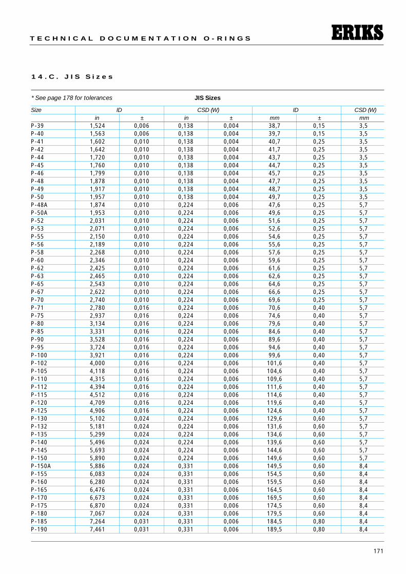
1 4 . C . J I S S i z e s
JIS Sizes
Size ID CSD (W) ID CSD (W)in ± in ± mm ± mm
P-39 1,524 0,006 0,138 0,004 38,7 0,15 3,5P-40 1,563 0,006 0,138 0,004 39,7 0,15 3,5P-41 1,602 0,010 0,138 0,004 40,7 0,25 3,5P-42 1,642 0,010 0,138 0,004 41,7 0,25 3,5P-44 1,720 0,010 0,138 0,004 43,7 0,25 3,5P-45 1,760 0,010 0,138 0,004 44,7 0,25 3,5P-46 1,799 0,010 0,138 0,004 45,7 0,25 3,5P-48 1,878 0,010 0,138 0,004 47,7 0,25 3,5P-49 1,917 0,010 0,138 0,004 48,7 0,25 3,5P-50 1,957 0,010 0,138 0,004 49,7 0,25 3,5P-48A 1,874 0,010 0,224 0,006 47,6 0,25 5,7P-50A 1,953 0,010 0,224 0,006 49,6 0,25 5,7P-52 2,031 0,010 0,224 0,006 51,6 0,25 5,7P-53 2,071 0,010 0,224 0,006 52,6 0,25 5,7P-55 2,150 0,010 0,224 0,006 54,6 0,25 5,7P-56 2,189 0,010 0,224 0,006 55,6 0,25 5,7P-58 2,268 0,010 0,224 0,006 57,6 0,25 5,7P-60 2,346 0,010 0,224 0,006 59,6 0,25 5,7P-62 2,425 0,010 0,224 0,006 61,6 0,25 5,7P-63 2,465 0,010 0,224 0,006 62,6 0,25 5,7P-65 2,543 0,010 0,224 0,006 64,6 0,25 5,7P-67 2,622 0,010 0,224 0,006 66,6 0,25 5,7P-70 2,740 0,010 0,224 0,006 69,6 0,25 5,7P-71 2,780 0,016 0,224 0,006 70,6 0,40 5,7P-75 2,937 0,016 0,224 0,006 74,6 0,40 5,7P-80 3,134 0,016 0,224 0,006 79,6 0,40 5,7P-85 3,331 0,016 0,224 0,006 84,6 0,40 5,7P-90 3,528 0,016 0,224 0,006 89,6 0,40 5,7P-95 3,724 0,016 0,224 0,006 94,6 0,40 5,7P-100 3,921 0,016 0,224 0,006 99,6 0,40 5,7P-102 4,000 0,016 0,224 0,006 101,6 0,40 5,7P-105 4,118 0,016 0,224 0,006 104,6 0,40 5,7P-110 4,315 0,016 0,224 0,006 109,6 0,40 5,7P-112 4,394 0,016 0,224 0,006 111,6 0,40 5,7P-115 4,512 0,016 0,224 0,006 114,6 0,40 5,7P-120 4,709 0,016 0,224 0,006 119,6 0,40 5,7P-125 4,906 0,016 0,224 0,006 124,6 0,40 5,7P-130 5,102 0,024 0,224 0,006 129,6 0,60 5,7P-132 5,181 0,024 0,224 0,006 131,6 0,60 5,7P-135 5,299 0,024 0,224 0,006 134,6 0,60 5,7P-140 5,496 0,024 0,224 0,006 139,6 0,60 5,7P-145 5,693 0,024 0,224 0,006 144,6 0,60 5,7P-150 5,890 0,024 0,224 0,006 149,6 0,60 5,7P-150A 5,886 0,024 0,331 0,006 149,5 0,60 8,4P-155 6,083 0,024 0,331 0,006 154,5 0,60 8,4P-160 6,280 0,024 0,331 0,006 159,5 0,60 8,4P-165 6,476 0,024 0,331 0,006 164,5 0,60 8,4P-170 6,673 0,024 0,331 0,006 169,5 0,60 8,4P-175 6,870 0,024 0,331 0,006 174,5 0,60 8,4P-180 7,067 0,024 0,331 0,006 179,5 0,60 8,4P-185 7,264 0,031 0,331 0,006 184,5 0,80 8,4P-190 7,461 0,031 0,331 0,006 189,5 0,80 8,4
* See page 178 for tolerances
172
S E A L I N G E L E M E N T S
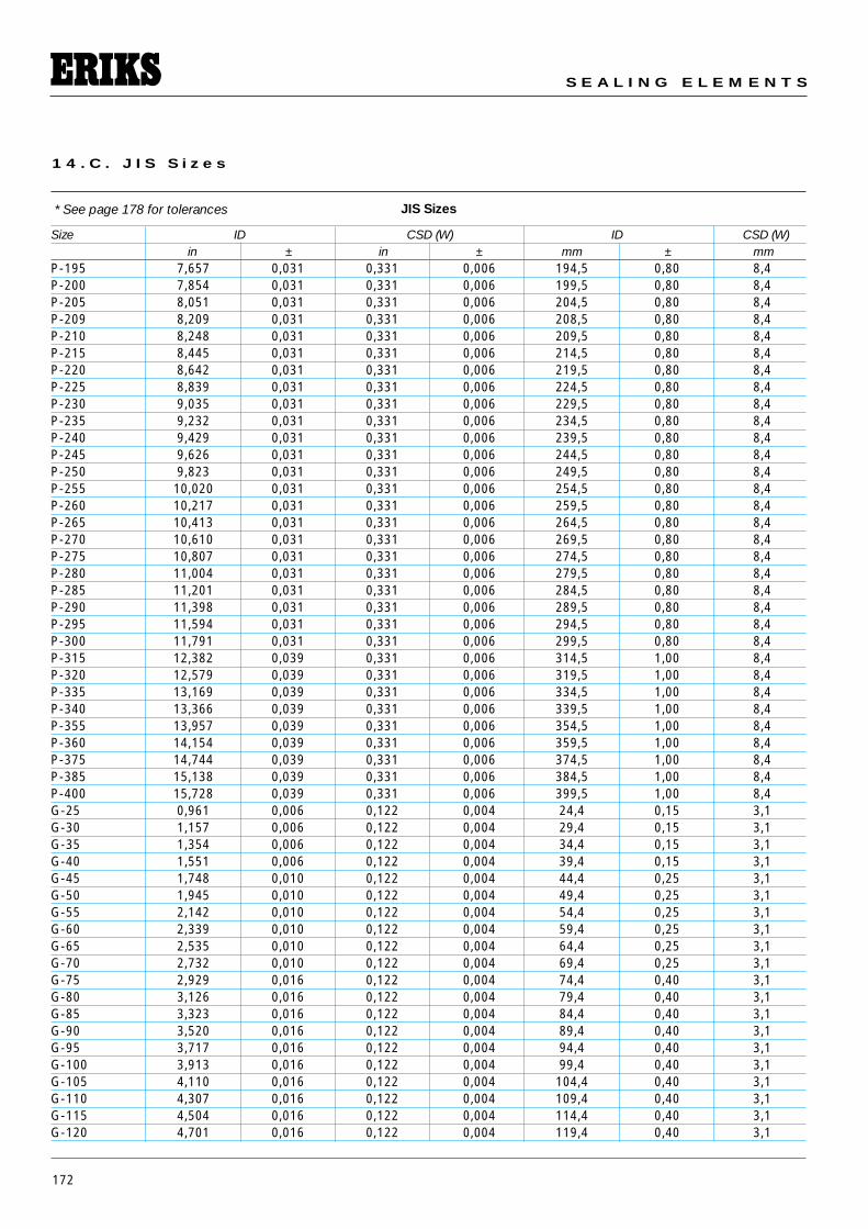
1 4 . C . J I S S i z e s
JIS Sizes
Size ID CSD (W) ID CSD (W)in ± in ± mm ± mm
P-195 7,657 0,031 0,331 0,006 194,5 0,80 8,4P-200 7,854 0,031 0,331 0,006 199,5 0,80 8,4P-205 8,051 0,031 0,331 0,006 204,5 0,80 8,4P-209 8,209 0,031 0,331 0,006 208,5 0,80 8,4P-210 8,248 0,031 0,331 0,006 209,5 0,80 8,4P-215 8,445 0,031 0,331 0,006 214,5 0,80 8,4P-220 8,642 0,031 0,331 0,006 219,5 0,80 8,4P-225 8,839 0,031 0,331 0,006 224,5 0,80 8,4P-230 9,035 0,031 0,331 0,006 229,5 0,80 8,4P-235 9,232 0,031 0,331 0,006 234,5 0,80 8,4P-240 9,429 0,031 0,331 0,006 239,5 0,80 8,4P-245 9,626 0,031 0,331 0,006 244,5 0,80 8,4P-250 9,823 0,031 0,331 0,006 249,5 0,80 8,4P-255 10,020 0,031 0,331 0,006 254,5 0,80 8,4P-260 10,217 0,031 0,331 0,006 259,5 0,80 8,4P-265 10,413 0,031 0,331 0,006 264,5 0,80 8,4P-270 10,610 0,031 0,331 0,006 269,5 0,80 8,4P-275 10,807 0,031 0,331 0,006 274,5 0,80 8,4P-280 11,004 0,031 0,331 0,006 279,5 0,80 8,4P-285 11,201 0,031 0,331 0,006 284,5 0,80 8,4P-290 11,398 0,031 0,331 0,006 289,5 0,80 8,4P-295 11,594 0,031 0,331 0,006 294,5 0,80 8,4P-300 11,791 0,031 0,331 0,006 299,5 0,80 8,4P-315 12,382 0,039 0,331 0,006 314,5 1,00 8,4P-320 12,579 0,039 0,331 0,006 319,5 1,00 8,4P-335 13,169 0,039 0,331 0,006 334,5 1,00 8,4P-340 13,366 0,039 0,331 0,006 339,5 1,00 8,4P-355 13,957 0,039 0,331 0,006 354,5 1,00 8,4P-360 14,154 0,039 0,331 0,006 359,5 1,00 8,4P-375 14,744 0,039 0,331 0,006 374,5 1,00 8,4P-385 15,138 0,039 0,331 0,006 384,5 1,00 8,4P-400 15,728 0,039 0,331 0,006 399,5 1,00 8,4G-25 0,961 0,006 0,122 0,004 24,4 0,15 3,1G-30 1,157 0,006 0,122 0,004 29,4 0,15 3,1G-35 1,354 0,006 0,122 0,004 34,4 0,15 3,1G-40 1,551 0,006 0,122 0,004 39,4 0,15 3,1G-45 1,748 0,010 0,122 0,004 44,4 0,25 3,1G-50 1,945 0,010 0,122 0,004 49,4 0,25 3,1G-55 2,142 0,010 0,122 0,004 54,4 0,25 3,1G-60 2,339 0,010 0,122 0,004 59,4 0,25 3,1G-65 2,535 0,010 0,122 0,004 64,4 0,25 3,1G-70 2,732 0,010 0,122 0,004 69,4 0,25 3,1G-75 2,929 0,016 0,122 0,004 74,4 0,40 3,1G-80 3,126 0,016 0,122 0,004 79,4 0,40 3,1G-85 3,323 0,016 0,122 0,004 84,4 0,40 3,1G-90 3,520 0,016 0,122 0,004 89,4 0,40 3,1G-95 3,717 0,016 0,122 0,004 94,4 0,40 3,1G-100 3,913 0,016 0,122 0,004 99,4 0,40 3,1G-105 4,110 0,016 0,122 0,004 104,4 0,40 3,1G-110 4,307 0,016 0,122 0,004 109,4 0,40 3,1G-115 4,504 0,016 0,122 0,004 114,4 0,40 3,1G-120 4,701 0,016 0,122 0,004 119,4 0,40 3,1
* See page 178 for tolerances
173
T E C H N I C A L D O C U M E N T A T I O N O - R I N G S
1 4 . C . J I S S i z e s
JIS Sizes
Size ID CSD (W) ID CSD (W)in ± in ± mm ± mm
G-125 4,898 0,016 0,122 0,004 124,4 0,40 3,1G-130 5,094 0,024 0,122 0,004 129,4 0,60 3,1G-135 5,291 0,024 0,122 0,004 134,4 0,60 3,1G-140 5,488 0,024 0,122 0,004 139,4 0,60 3,1G-145 5,685 0,024 0,122 0,004 144,4 0,60 3,1G-150 5,878 0,024 0,224 0,006 149,3 0,60 5,7G-155 6,075 0,024 0,224 0,006 154,3 0,60 5,7G-160 6,272 0,024 0,224 0,006 159,3 0,60 5,7G-165 6,469 0,024 0,224 0,006 164,3 0,60 5,7G-170 6,665 0,024 0,224 0,006 169,3 0,60 5,7G-175 6,862 0,024 0,224 0,006 174,3 0,60 5,7G-180 7,059 0,024 0,224 0,006 179,3 0,60 5,7G-185 7,256 0,031 0,224 0,006 184,3 0,80 5,7G-190 7,453 0,031 0,224 0,006 189,3 0,80 5,7G-195 7,650 0,031 0,224 0,006 194,3 0,80 5,7G-200 7,846 0,031 0,224 0,006 199,3 0,80 5,7G-210 8,240 0,031 0,224 0,006 209,3 0,80 5,7G-220 8,634 0,031 0,224 0,006 219,3 0,80 5,7G-230 9,028 0,031 0,224 0,006 229,3 0,80 5,7G-240 9,421 0,031 0,224 0,006 239,3 0,80 5,7G-250 9,815 0,031 0,224 0,006 249,3 0,80 5,7G-255 10,012 0,031 0,224 0,006 254,3 0,80 5,7G-260 10,209 0,031 0,224 0,006 259,3 0,80 5,7G-270 10,602 0,031 0,224 0,006 269,3 0,80 5,7G-280 10,996 0,031 0,224 0,006 279,3 0,80 5,7G-290 11,390 0,031 0,224 0,006 289,3 0,80 5,7G-300 11,783 0,031 0,224 0,006 299,3 0,80 5,7V-15 0,571 0,006 0,157 0,004 14,5 0,15 4,0V-24 0,925 0,006 0,157 0,004 23,5 0,15 4,0V-34 1,319 0,006 0,157 0,004 33,5 0,15 4,0V-40 1,555 0,006 0,157 0,004 39,5 0,15 4,0V-55 2,146 0,010 0,157 0,004 54,5 0,25 4,0V-70 2,717 0,010 0,157 0,004 69,0 0,25 4,0V-85 3,307 0,016 0,157 0,004 84,0 0,40 4,0V-100 3,898 0,016 0,157 0,004 99,0 0,40 4,0V-120 4,685 0,016 0,157 0,004 119,0 0,40 4,0V-150 5,846 0,024 0,157 0,004 148,5 0,60 4,0V-175 6,811 0,024 0,157 0,004 173,0 0,60 4,0V-225 8,760 0,031 0,236 0,006 222,5 0,80 6,0V-275 10,709 0,031 0,236 0,006 272,0 0,80 6,0V-325 12,657 0,039 0,236 0,006 321,5 1,00 6,0V-380 14,803 0,039 0,236 0,006 376,0 1,00 6,0V-430 16,752 0,047 0,236 0,006 425,5 1,20 6,0V-480 18,701 0,047 0,394 0,012 475,0 1,20 10,0V-530 20,650 0,063 0,394 0,012 524,5 1,60 10,0V-585 22,795 0,063 0,394 0,012 579,0 1,60 10,0V-640 24,941 0,063 0,394 0,012 633,5 1,60 10,0V-690 26,890 0,063 0,394 0,012 683,0 1,60 10,0V-740 28,839 0,079 0,394 0,012 732,5 2,00 10,0V-790 30,787 0,079 0,394 0,012 782,0 2,00 10,0V-845 32,933 0,079 0,394 0,012 836,5 2,00 10,0V-950 37,028 0,098 0,394 0,012 940,5 2,50 10,0V-1055 41,102 0,118 0,394 0,012 1044,0 3,00 10,0
* See page 178 for tolerances
174
S E A L I N G E L E M E N T S
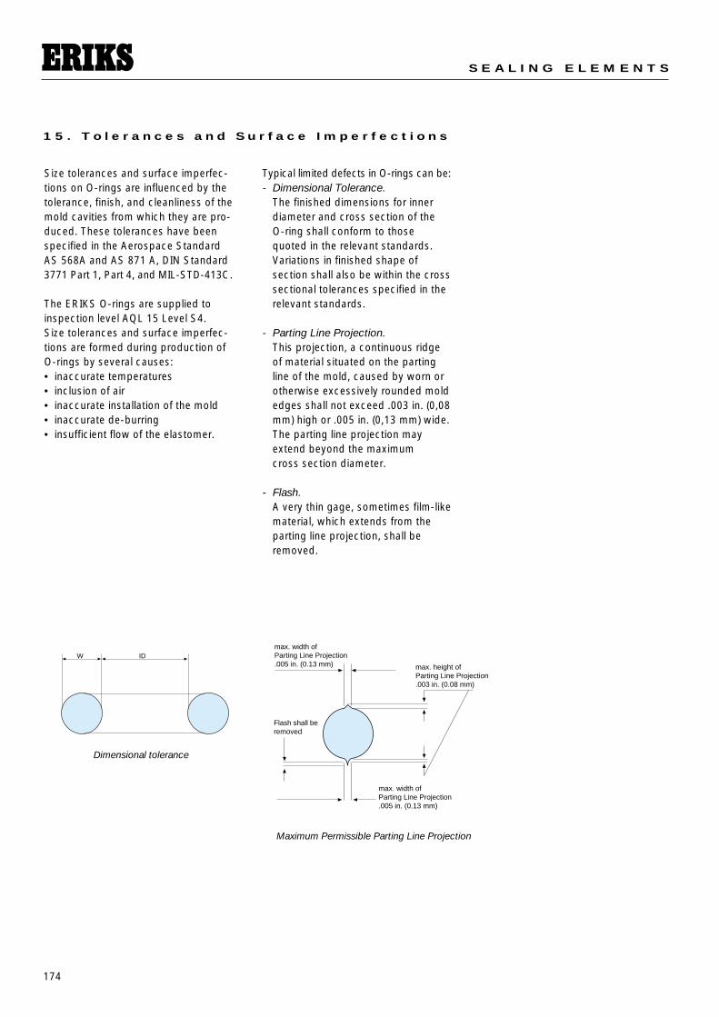
1 5 . T o l e r a n c e s a n d S u r f a c e I m p e r f e c t i o n s
Size tolerances and surface imperfec-tions on O-rings are influenced by thetolerance, finish, and cleanliness of themold cavities from which they are pro-duced. These tolerances have beenspecified in the Aerospace StandardAS 568A and AS 871 A, DIN Standard3771 Part 1, Part 4, and MIL-STD-413C.
The ERIKS O-rings are supplied toinspection level AQL 15 Level S4.Size tolerances and surface imperfec-tions are formed during production ofO-rings by several causes:• inaccurate temperatures• inclusion of air • inaccurate installation of the mold• inaccurate de-burring• insufficient flow of the elastomer.
W IDmax. width ofParting Line Projection.005 in. (0.13 mm) max. height of
Parting Line Projection.003 in. (0.08 mm)
max. width ofParting Line Projection.005 in. (0.13 mm)
Flash shall beremoved
Dimensional tolerance
Maximum Permissible Parting Line Projection
Typical limited defects in O-rings can be:- Dimensional Tolerance.
The finished dimensions for innerdiameter and cross section of the O-ring shall conform to those quoted in the relevant standards.Variations in finished shape of section shall also be within the crosssectional tolerances specified in therelevant standards.
- Parting Line Projection. This projection, a continuous ridgeof material situated on the partingline of the mold, caused by worn orotherwise excessively rounded moldedges shall not exceed .003 in. (0,08mm) high or .005 in. (0,13 mm) wide.The parting line projection mayextend beyond the maximum cross section diameter.
- Flash. A very thin gage, sometimes film-likematerial, which extends from theparting line projection, shall beremoved.
175
T E C H N I C A L D O C U M E N T A T I O N O - R I N G S
1 5 . T o l e r a n c e s a n d S u r f a c e I m p e r f e c t i o n s
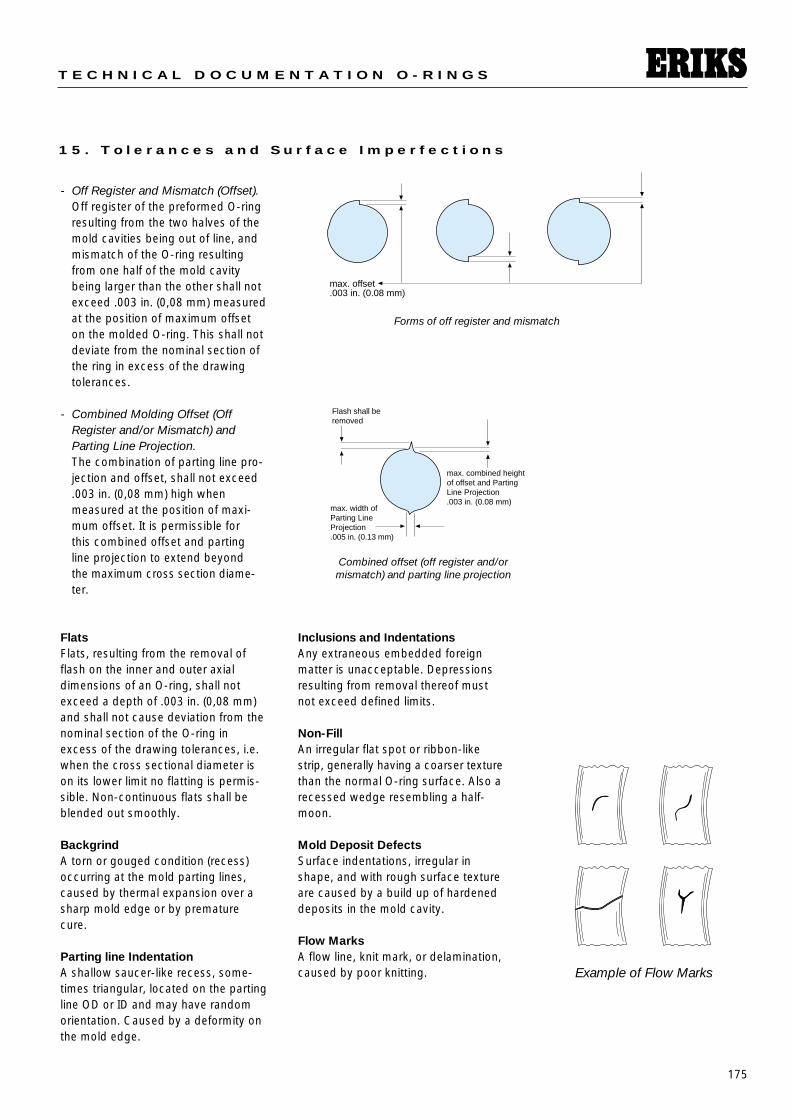
- Off Register and Mismatch (Offset).Off register of the preformed O-ringresulting from the two halves of themold cavities being out of line, andmismatch of the O-ring resultingfrom one half of the mold cavitybeing larger than the other shall notexceed .003 in. (0,08 mm) measuredat the position of maximum offseton the molded O-ring. This shall notdeviate from the nominal section ofthe ring in excess of the drawing tolerances.
- Combined Molding Offset (OffRegister and/or Mismatch) andParting Line Projection. The combination of parting line pro-jection and offset, shall not exceed.003 in. (0,08 mm) high when measured at the position of maxi-mum offset. It is permissible for this combined offset and parting line projection to extend beyond the maximum cross section diame-ter.
max. offset.003 in. (0.08 mm)
max. width ofParting LineProjection.005 in. (0.13 mm)
max. combined heightof offset and PartingLine Projection.003 in. (0.08 mm)
Flash shall beremoved
Example of Flow Marks
Flats Flats, resulting from the removal offlash on the inner and outer axialdimensions of an O-ring, shall notexceed a depth of .003 in. (0,08 mm)and shall not cause deviation from thenominal section of the O-ring inexcess of the drawing tolerances, i.e.when the cross sectional diameter ison its lower limit no flatting is permis-sible. Non-continuous flats shall beblended out smoothly.
BackgrindA torn or gouged condition (recess)occurring at the mold parting lines,caused by thermal expansion over asharp mold edge or by prematurecure.
Parting line IndentationA shallow saucer-like recess, some-times triangular, located on the partingline OD or ID and may have randomorientation. Caused by a deformity onthe mold edge.
Inclusions and IndentationsAny extraneous embedded foreignmatter is unacceptable. Depressionsresulting from removal thereof mustnot exceed defined limits.
Non-FillAn irregular flat spot or ribbon-likestrip, generally having a coarser texturethan the normal O-ring surface. Also arecessed wedge resembling a half-moon.
Mold Deposit DefectsSurface indentations, irregular inshape, and with rough surface textureare caused by a build up of hardeneddeposits in the mold cavity.
Flow MarksA flow line, knit mark, or delamination,caused by poor knitting.
Forms of off register and mismatch
Combined offset (off register and/or mismatch) and parting line projection
176
S E A L I N G E L E M E N T S
1 5 . T o l e r a n c e s a n d S u r f a c e I m p e r f e c t i o n s
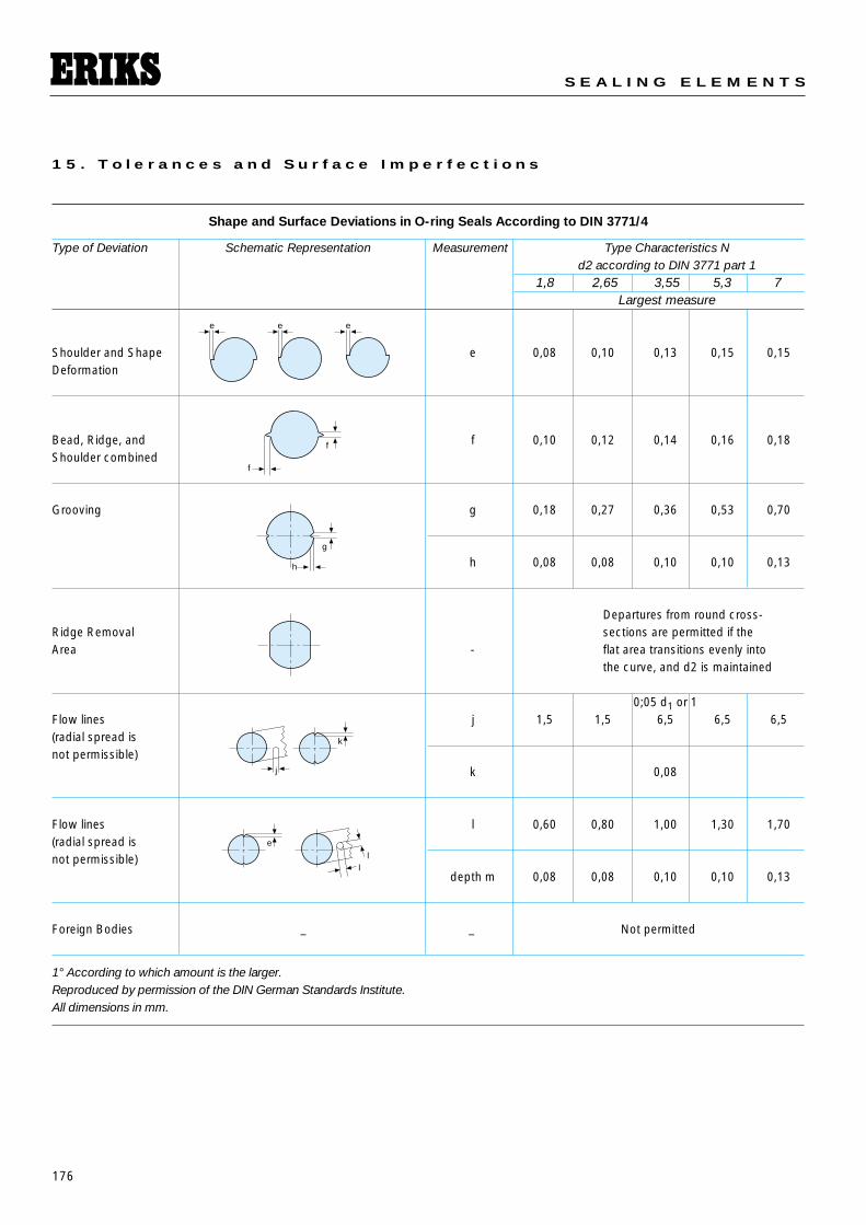
Shape and Surface Deviations in O-ring Seals According to DIN 3771/4
Type of Deviation Schematic Representation Measurement Type Characteristics Nd2 according to DIN 3771 part 1
1,8 2,65 3,55 5,3 7Largest measure
Shoulder and Shape e 0,08 0,10 0,13 0,15 0,15Deformation
Bead, Ridge, and f 0,10 0,12 0,14 0,16 0,18Shoulder combined
Grooving g 0,18 0,27 0,36 0,53 0,70
h 0,08 0,08 0,10 0,10 0,13
Departures from round cross-Ridge Removal sections are permitted if theArea - flat area transitions evenly into
the curve, and d2 is maintained
0;05 d1 or 1Flow lines j 1,5 1,5 6,5 6,5 6,5(radial spread isnot permissible)
k 0,08
Flow lines l 0,60 0,80 1,00 1,30 1,70(radial spread isnot permissible)
depth m 0,08 0,08 0,10 0,10 0,13
Foreign Bodies _ _ Not permitted
1° According to which amount is the larger.Reproduced by permission of the DIN German Standards Institute.All dimensions in mm.
e e e
f
f
g
h
k
j
e
ll
177
T E C H N I C A L D O C U M E N T A T I O N O - R I N G S
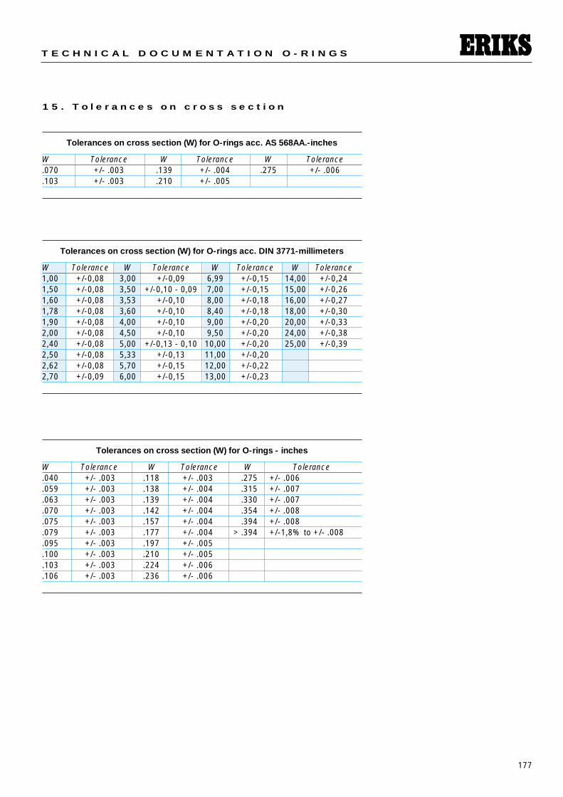
1 5 . T o l e r a n c e s o n c r o s s s e c t i o n
Tolerances on cross section (W) for O-rings acc. AS 568AA.-inches
W Tolerance W Tolerance W Tolerance.070 +/- .003 .139 +/- .004 .275 +/- .006.103 +/- .003 .210 +/- .005
Tolerances on cross section (W) for O-rings acc. DIN 3771-millimeters
W Tolerance W Tolerance W Tolerance W Tolerance1,00 +/-0,08 3,00 +/-0,09 6,99 +/-0,15 14,00 +/-0,241,50 +/-0,08 3,50 +/-0,10 - 0,09 7,00 +/-0,15 15,00 +/-0,261,60 +/-0,08 3,53 +/-0,10 8,00 +/-0,18 16,00 +/-0,271,78 +/-0,08 3,60 +/-0,10 8,40 +/-0,18 18,00 +/-0,301,90 +/-0,08 4,00 +/-0,10 9,00 +/-0,20 20,00 +/-0,332,00 +/-0,08 4,50 +/-0,10 9,50 +/-0,20 24,00 +/-0,382,40 +/-0,08 5,00 +/-0,13 - 0,10 10,00 +/-0,20 25,00 +/-0,392,50 +/-0,08 5,33 +/-0,13 11,00 +/-0,202,62 +/-0,08 5,70 +/-0,15 12,00 +/-0,222,70 +/-0,09 6,00 +/-0,15 13,00 +/-0,23
Tolerances on cross section (W) for O-rings - inches
W Tolerance W Tolerance W Tolerance.040 +/- .003 .118 +/- .003 .275 +/- .006.059 +/- .003 .138 +/- .004 .315 +/- .007.063 +/- .003 .139 +/- .004 .330 +/- .007.070 +/- .003 .142 +/- .004 .354 +/- .008.075 +/- .003 .157 +/- .004 .394 +/- .008.079 +/- .003 .177 +/- .004 > .394 +/-1,8% to +/- .008.095 +/- .003 .197 +/- .005.100 +/- .003 .210 +/- .005.103 +/- .003 .224 +/- .006.106 +/- .003 .236 +/- .006
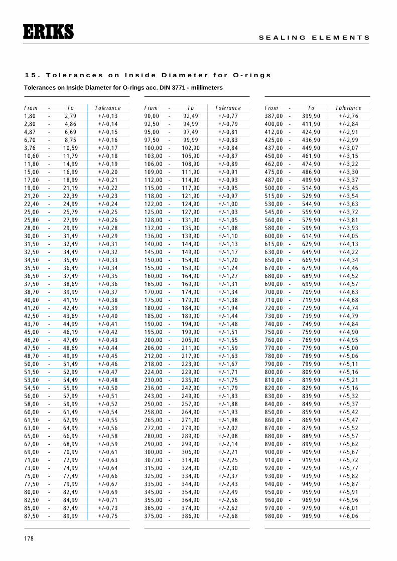
178
S E A L I N G E L E M E N T S
1 5 . T o l e r a n c e s o n I n s i d e D i a m e t e r f o r O - r i n g s
From - To Tolerance1,80 - 2,79 +/-0,13 2,80 - 4,86 +/-0,14 4,87 - 6,69 +/-0,15 6,70 - 8,75 +/-0,16 3,76 - 10,59 +/-0,17 10,60 - 11,79 +/-0,18 11,80 - 14,99 +/-0,19 15,00 - 16,99 +/-0,20 17,00 - 18,99 +/-0,21 19,00 - 21,19 +/-0,22 21,20 - 22,39 +/-0,23 22,40 - 24,99 +/-0,24 25,00 - 25,79 +/-0,25 25,80 - 27,99 +/-0,26 28,00 - 29,99 +/-0,28 30,00 - 31,49 +/-0,29 31,50 - 32,49 +/-0,31 32,50 - 34,49 +/-0,32 34,50 - 35,49 +/-0,33 35,50 - 36,49 +/-0,34 36,50 - 37,49 +/-0,35 37,50 - 38,69 +/-0,36 38,70 - 39,99 +/-0,37 40,00 - 41,19 +/-0,38 41,20 - 42,49 +/-0,39 42,50 - 43,69 +/-0,40 43,70 - 44,99 +/-0,41 45,00 - 46,19 +/-0,42 46,20 - 47,49 +/-0,43 47,50 - 48,69 +/-0,44 48,70 - 49,99 +/-0,4550,00 - 51,49 +/-0,4651,50 - 52,99 +/-0,4753,00 - 54,49 +/-0,4854,50 - 55,99 +/-0,50 56,00 - 57,99 +/-0,51 58,00 - 59,99 +/-0,52 60,00 - 61,49 +/-0,5461,50 - 62,99 +/-0,5563,00 - 64,99 +/-0,5665,00 - 66,99 +/-0,5867,00 - 68,99 +/-0,5969,00 - 70,99 +/-0,6171,00 - 72,99 +/-0,6373,00 - 74,99 +/-0,6475,00 - 77,49 +/-0,6677,50 - 79,99 +/-0,6780,00 - 82,49 +/-0,6982,50 - 84,99 +/-0,7185,00 - 87,49 +/-0,7387,50 - 89,99 +/-0,75
From - To Tolerance90,00 - 92,49 +/-0,7792,50 - 94,99 +/-0,7995,00 - 97,49 +/-0,8197,50 - 99,99 +/-0,83100,00 - 102,90 +/-0,84103,00 - 105,90 +/-0,87106,00 - 108,90 +/-0,89109,00 - 111,90 +/-0,91112,00 - 114,90 +/-0,93115,00 - 117,90 +/-0,95118,00 - 121,90 +/-0,97122,00 - 124,90 +/-1,00125,00 - 127,90 +/-1,03128,00 - 131,90 +/-1,05132,00 - 135,90 +/-1,08136,00 - 139,90 +/-1,10140,00 - 144,90 +/-1,13145,00 - 149,90 +/-1,17150,00 - 154,90 +/-1,20155,00 - 159,90 +/-1,24160,00 - 164,90 +/-1,27165,00 - 169,90 +/-1,31170,00 - 174,90 +/-1,34175,00 - 179,90 +/-1,38180,00 - 184,90 +/-1,94185,00 - 189,90 +/-1,44190,00 - 194,90 +/-1,48195,00 - 199,90 +/-1,51200,00 - 205,90 +/-1,55 206,00 - 211,90 +/-1,59212,00 - 217,90 +/-1,63218,00 - 223,90 +/-1,67224,00 - 229,90 +/-1,71 230,00 - 235,90 +/-1,75236,00 - 242,90 +/-1,79243,00 - 249,90 +/-1,83250,00 - 257,90 +/-1,88258,00 - 264,90 +/-1,93265,00 - 271,90 +/-1,98272,00 - 279,90 +/-2,02280,00 - 289,90 +/-2,08290,00 - 299,90 +/-2,14300,00 - 306,90 +/-2,21307,00 - 314,90 +/-2,25315,00 - 324,90 +/-2,30325,00 - 334,90 +/-2,37335,00 - 344,90 +/-2,43345,00 - 354,90 +/-2,49355,00 - 364,90 +/-2,56365,00 - 374,90 +/-2,62375,00 - 386,90 +/-2,68
From - To Tolerance387,00 - 399,90 +/-2,76400,00 - 411,90 +/-2,84412,00 - 424,90 +/-2,91425,00 - 436,90 +/-2,99437,00 - 449,90 +/-3,07450,00 - 461,90 +/-3,15462,00 - 474,90 +/-3,22475,00 - 486,90 +/-3,30487,00 - 499,90 +/-3,37500,00 - 514,90 +/-3,45 515,00 - 529,90 +/-3,54530,00 - 544,90 +/-3,63 545,00 - 559,90 +/-3,72 560,00 - 579,90 +/-3,81 580,00 - 599,90 +/-3,93 600,00 - 614,90 +/-4,05 615,00 - 629,90 +/-4,13630,00 - 649,90 +/-4,22650,00 - 669,90 +/-4,34670,00 - 679,90 +/-4,46680,00 - 689,90 +/-4,52690,00 - 699,90 +/-4,57700,00 - 709,90 +/-4,63710,00 - 719,90 +/-4,68720,00 - 729,90 +/-4,74730,00 - 739,90 +/-4,79740,00 - 749,90 +/-4,84750,00 - 759,90 +/-4,90760,00 - 769,90 +/-4,95770,00 - 779,90 +/-5,00780,00 - 789,90 +/-5,06790,00 - 799,90 +/-5,11800,00 - 809,90 +/-5,16810,00 - 819,90 +/-5,21820,00 - 829,90 +/-5,16830,00 - 839,90 +/-5,32840,00 - 849,90 +/-5,37850,00 - 859,90 +/-5,42860,00 - 869,90 +/-5,47870,00 - 879,90 +/-5,52880,00 - 889,90 +/-5,57890,00 - 899,90 +/-5,62900,00 - 909,90 +/-5,67910,00 - 919,90 +/-5,72920,00 - 929,90 +/-5,77930,00 - 939,90 +/-5,82940,00 - 949,90 +/-5,87950,00 - 959,90 +/-5,91960,00 - 969,90 +/-5,96970,00 - 979,90 +/-6,01980,00 - 989,90 +/-6,06
Tolerances on Inside Diameter for O-rings acc. DIN 3771 - millimeters
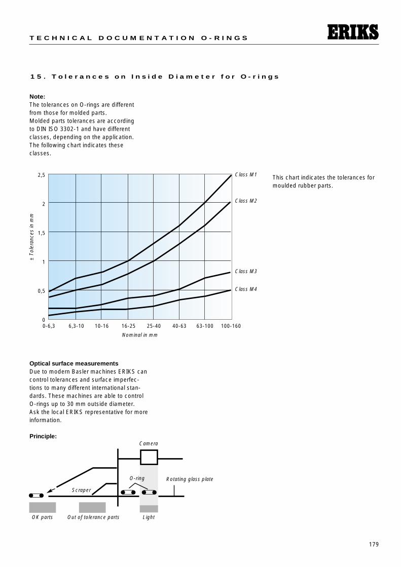
179
T E C H N I C A L D O C U M E N T A T I O N O - R I N G S
1 5 . T o l e r a n c e s o n I n s i d e D i a m e t e r f o r O - r i n g s
Note:The tolerances on O-rings are differentfrom those for molded parts.Molded parts tolerances are accordingto DIN ISO 3302-1 and have differentclasses, depending on the application.The following chart indicates theseclasses.
Optical surface measurementsDue to modern Basler machines ERIKS cancontrol tolerances and surface imperfec-tions to many different international stan-dards. These machines are able to controlO-rings up to 30 mm outside diameter.Ask the local ERIKS representative for moreinformation.
Principle:
0-6,3 6,3-10 10-16 16-25 25-40 40-63 63-100 100-160
2,5
2
1,5
1
0,5
0
Nominal in mm
Class M1
Class M2
Class M3
Class M4
±To
lera
nces
in m
m
Camera
OK parts Light
Scraper
Out of tolerance parts
Rotating glass plateO-ring
This chart indicates the tolerances formoulded rubber parts.
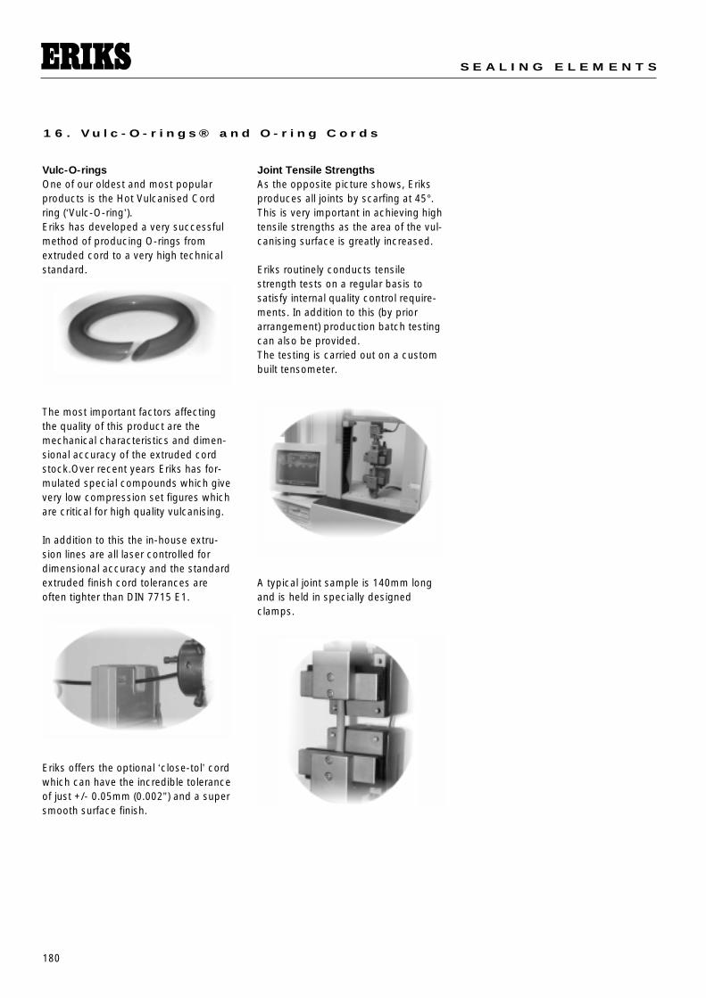
180
S E A L I N G E L E M E N T S
1 6 . V u l c - O - r i n g s ® a n d O - r i n g C o r d s
Vulc-O-ringsOne of our oldest and most popularproducts is the Hot Vulcanised Cordring (‘Vulc-O-ring’).Eriks has developed a very successfulmethod of producing O-rings fromextruded cord to a very high technicalstandard.
The most important factors affectingthe quality of this product are themechanical characteristics and dimen-sional accuracy of the extruded cordstock.Over recent years Eriks has for-mulated special compounds which givevery low compression set figures whichare critical for high quality vulcanising.
In addition to this the in-house extru-sion lines are all laser controlled fordimensional accuracy and the standardextruded finish cord tolerances areoften tighter than DIN 7715 E1.
Eriks offers the optional ‘close-tol’ cordwhich can have the incredible toleranceof just +/- 0.05mm (0.002”) and a supersmooth surface finish.
Joint Tensile StrengthsAs the opposite picture shows, Eriksproduces all joints by scarfing at 45°.This is very important in achieving hightensile strengths as the area of the vul-canising surface is greatly increased.
Eriks routinely conducts tensilestrength tests on a regular basis tosatisfy internal quality control require-ments. In addition to this (by priorarrangement) production batch testingcan also be provided.The testing is carried out on a custombuilt tensometer.
A typical joint sample is 140mm longand is held in specially designedclamps.
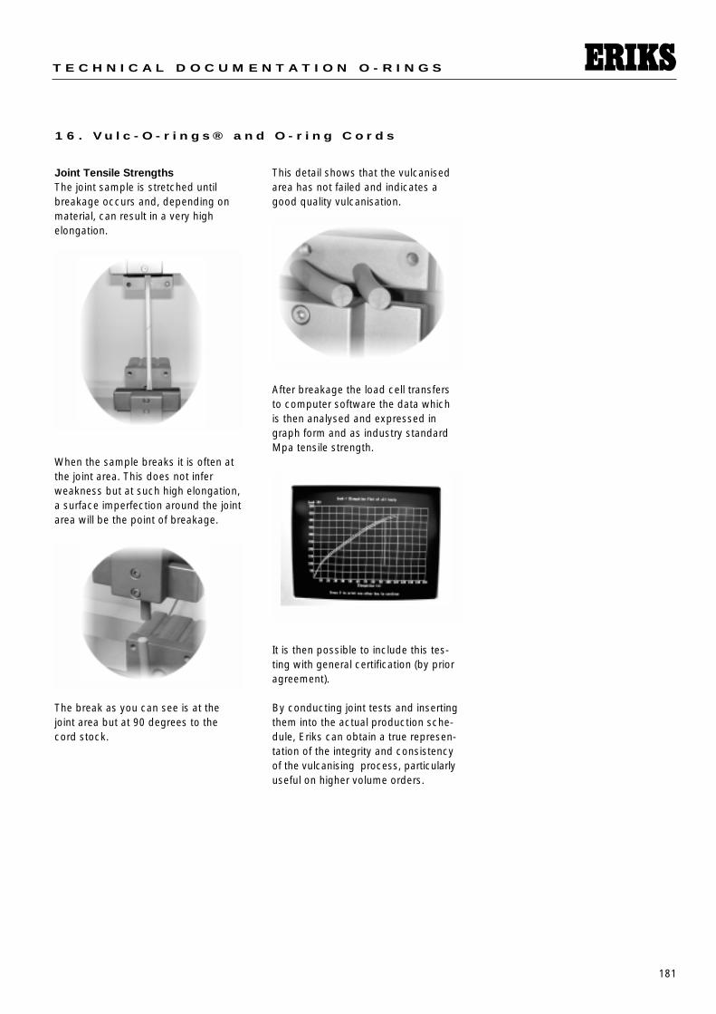
181
T E C H N I C A L D O C U M E N T A T I O N O - R I N G S
1 6 . V u l c - O - r i n g s ® a n d O - r i n g C o r d s
Joint Tensile StrengthsThe joint sample is stretched until breakage occurs and, depending onmaterial, can result in a very high elongation.
When the sample breaks it is often atthe joint area. This does not inferweakness but at such high elongation,a surface imperfection around the jointarea will be the point of breakage.
The break as you can see is at thejoint area but at 90 degrees to thecord stock.
This detail shows that the vulcanisedarea has not failed and indicates agood quality vulcanisation.
After breakage the load cell transfersto computer software the data whichis then analysed and expressed ingraph form and as industry standardMpa tensile strength.
It is then possible to include this tes-ting with general certification (by prioragreement).
By conducting joint tests and insertingthem into the actual production sche-dule, Eriks can obtain a true represen-tation of the integrity and consistencyof the vulcanising process, particularlyuseful on higher volume orders.
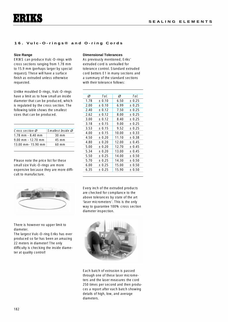
182
S E A L I N G E L E M E N T S
1 6 . V u l c - O - r i n g s ® a n d O - r i n g C o r d s
Size RangeERIKS can produce Vulc-O-rings withcross sections ranging from 1.78 mmto 15.9 mm (perhaps larger by specialrequest). These will have a surface finish as extruded unless otherwiserequested.
Unlike moulded O-rings, Vulc-O-ringshave a limit as to how small an insidediameter that can be produced, whichis regulated by the cross section. Thefollowing table shows the smallestsizes that can be produced.
Please note the price list for thesesmall size Vulc-O-rings are moreexpensive because they are more diffi-cult to manufacture.
There is however no upper limit todiameter.The largest Vulc-O-ring Eriks has everproduced so far has been an amazing22 meters in diameter! The only difficulty is checking the inside diame-ter at quality control!
Dimensional TolerancesAs previously mentioned, Eriks’extruded cord is unrivalled for tolerance control. Standard extrudedcord betters E1 in many sections anda summary of the standard sectionswith their tolerance follows:
Every inch of the extruded productsare checked for compliance to theabove tolerances by state of the art‘laser micrometers’. This is the onlyway to guarantee 100% cross sectiondiameter inspection.
Each batch of extrusion is passedthrough one of these laser microme-ters and the laser measures the cord250 times per second and then produ-ces a report after each batch showingdetails of high, low, and average diameters.
Cross section Ø Smallest Inside Ø1.78 mm - 8.40 mm 30 mm9.00 mm - 12.70 mm 45 mm13.00 mm- 15.90 mm 60 mm
Ø Tol. Ø Tol.1.78 ± 0.10 6.50 ± 0.252.00 ± 0.10 6.99 ± 0.252.40 ± 0.12 7.50 ± 0.252.62 ± 0.12 8.00 ± 0.253.00 ± 0.12 8.40 ± 0.253.18 ± 0.15 9.00 ± 0.253.53 ± 0.15 9.52 ± 0.254.00 ± 0.15 10.00 ± 0.334.50 ± 0.20 11.10 ± 0.384.80 ± 0.20 12.00 ± 0.455.00 ± 0.20 12.70 ± 0.455.34 ± 0.20 13.00 ± 0.455.50 ± 0.25 14.00 ± 0.505.70 ± 0.25 14.30 ± 0.506.00 ± 0.25 15.00 ± 0.506.35 ± 0.25 15.90 ± 0.50
183
T E C H N I C A L D O C U M E N T A T I O N O - R I N G S
1 6 . V u l c - O - r i n g s ® a n d O - r i n g C o r d s
Inside diameters are controlled accor-ding to DIN 7715 M2F as Vulc-O-ringsfrequently fall outside the range of diameters controlled by BS or AS standard sizes.
MaterialsERIKS maintains a standard range ofmaterials in compound form forspeedy conversion into extruded cord.This is a different policy than of holdingcord on the shelf. There are more andmore clients asking for current quartercure dates and this policy ensures thatthe user gets this rather than cordwhich may have been on the shelf forlonger.
Other materials, colors and hardness’smay be possible to special manufactu-re. Contact ERIKS with any requirements.
Benefits of Vulc-O-ringsThe main benefits of utilising Vulc-O-rings are listed as follows.
• Molds are not required resulting inhuge cost savings
• No upper diameter restrictions likemolding
• Tolerances can be closer than mol-ding
• No flash lines are present• Can be used in standard housings• Shapes other than round are possible• Joints in some cases 90% of cord
strength• Short lead times (48 hour turn around
possible)
Inside diameter Tolerance
25mm thru 40mm +/- 0.35
40.1mm thru 63mm +/- 0.40
63.1mm thru 100mm +/- 0.50
100.1mm thru 160mm +/- 0.70
Hereafter the tolerance will be +/- 0.5% of
the nominal inside diameter of the ring
Example: inside diameter of 310.0mm
tolerance = +/- 1.55mm (0.5%)
Restrictions of Vulc-O-ringsThere are however areas where Vulc-O-rings are restrictive.
• Dynamic applications where roll mayoccur.
• Excessive stretching- low strengthmaterials.
• Not possible below hardness of 60Shore A.
• Not competitive against mouldedrings when small diameters in highvolume.
Lead Times for Vulc-O-ringsPrice list Vulc-O-rings up to 100 pcswill be shipped within seven workingdays from receipt of order.Other volumes and sizes are availablebased on the application.
silicone 75 Red FDA
Fluorosilicone 75 BlueViton A 60Viton A 75Viton A 90
Polyurethane 75
NBR 60NBR 75NBR 90
Viton A 60 BrownViton A 75 BrownViton A 75 GreenViton A 90 Green
Viton A 75 FDAFKM B 90 EDRViton-Extreme
Chloroprene 60Chloroprene 75
Chloroprene 75 FDA
EPDM 60EPDM 75
EPDM 75 FDA
Aflas 75Aflas 90
Viton GF 75Viton GLT 75
Viton GFLT 75
NBR 75 FDA
XNBR 75HNBR 75
184
S E A L I N G E L E M E N T S
1 6 . V u l c - O - r i n g s ® a n d O - r i n g C o r d s
16.2 Rubber O-ring CordThe table shows the available stockcord dimensions and elastomers.Upon request cord in special elasto-mers or special dimensions can besupplied.
Available materials:Nitrile NBR 70° shore A, NBR 90°shore A, Fluorocarbon FKM 70° shoreA, FKM 75° shore A, Neoprene CR 60°shore A, EPDM 70° shore A, SiliconeMVQ 60° shore A, PolyurethaneAU/EU 90° shore A, and Para NR 40°shore A. Other elastomers, hardnesses,or special colors can also be supplied.
An O-ring splicing kit is available withthe materials required for cold bondingof custom size O-rings. Please note that vulcanized or splicedO-rings are only recommended for static applications.For full information ask for the specialbrochure: Vulc-O-rings® or contact thelocal ERIKS representative.
Rubber Cord
Cross section NR Para NBR Nitrile Polyure- CR. EPDM FKM fluorocarbon MVQ Siliconethane Neoprene
inch mm 40° sh 70°sh 90°sh 90°sh 60°sh 70°sh 70°sh 75°sh 60°sh 60°sh 60°shOriginal 714 BF 714 THT 714 MP
Viton FDA/BGA FDA/BGATol.E2 Tol.E2 Tol.E2 Tol.E2 Tol.E2 Tol.E2 Tol.E2 Tol.E1 Tol.E2 Tol.E2 Tol.E2brown black black green white black black black transp. grey grey
.063 1,60 X X X
.070 1,78 X X X
.079 2,00 X X X X
.094 2,40 X X
.098 2,50 X X
.103 2,62 X X X X
.118 3,00 X X X X X X X X X X
.128 3,25 X
.139 3,53 X X X X X X X
.157 4,00 X X X X X X X X X X
.177 4,50 X X
.187 4,75 X
.197 5,00 X X X X X X X X X X
.210 5,33 X X X X
.224 5,70 X X X X X
.236 6,00 X X X X X X X X X X
.250 6,35 X X
.256 6,50 X
.276 7,00 X X X X X X X X X X
.295 7,50 X
.315 8,00 X X X X X X X X X X X
.331 8,40 X X X
.354 9,00 X X X X X X
.374 9,50 X
.394 10,00 X X X X X X X X X X
.433 11,00 X X X
.472 12,00 X X X X X X X X X
.512 13,00 X X X X
.551 14,00 X X X X
.571 14,50 X
.591 15,00 X X X X X X
.630 16,00 X X X X X
.669 17,00 X
.709 18,00 X X X X
.787 20,00 X X X X X X
.866 22,00 X X X X
.906 23,00 X X
.984 25,00 X X X X1.181 30,00 X X X1.220 31,00 X1.260 32,00 X 1.575 40,00 X
All hardness values were measured on the shore A scale.
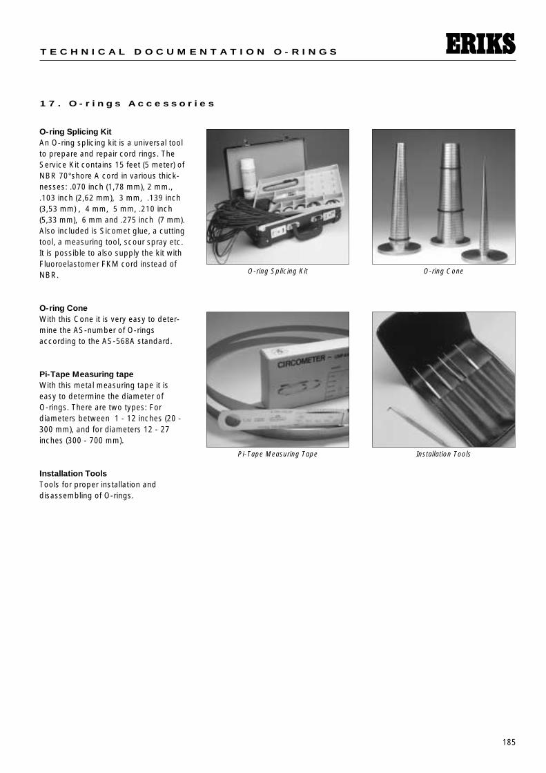
185
T E C H N I C A L D O C U M E N T A T I O N O - R I N G S
1 7 . O - r i n g s A c c e s s o r i e s
O-ring Splicing KitAn O-ring splicing kit is a universal toolto prepare and repair cord rings. TheService Kit contains 15 feet (5 meter) ofNBR 70°shore A cord in various thick-nesses: .070 inch (1,78 mm), 2 mm.,.103 inch (2,62 mm), 3 mm, .139 inch(3,53 mm) , 4 mm, 5 mm, .210 inch(5,33 mm), 6 mm and .275 inch (7 mm).Also included is Sicomet glue, a cuttingtool, a measuring tool, scour spray etc.It is possible to also supply the kit withFluoroelastomer FKM cord instead ofNBR.
O-ring ConeWith this Cone it is very easy to deter-mine the AS-number of O-ringsaccording to the AS-568A standard.
Pi-Tape Measuring tapeWith this metal measuring tape it iseasy to determine the diameter of O-rings. There are two types: For diameters between 1 - 12 inches (20 -300 mm), and for diameters 12 - 27inches (300 - 700 mm).
Installation ToolsTools for proper installation and disassembling of O-rings.
O-ring Splicing Kit O-ring Cone
Pi-Tape Measuring Tape Installation Tools
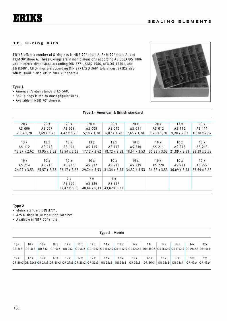
186
S E A L I N G E L E M E N T S
1 8 . O - r i n g K i t s
Type 1 - American & British standard
20 x 20 x 20 x 20 x 20 x 20 x 20 x 13 x 13 xAS 006 AS 007 AS 008 AS 009 AS 010 AS 011 AS 012 AS 110 AS 111
2,9 x 1,78 3,69 x 1,78 4,47 x 1,78 5,18 x 1,78 6,07 x 1,78 7,65 x 1,78 9,25 x 1,78 9,20 x 2,62 10,78 x 2,62
13 x 13 x 13 x 13 x 13 x 10 x 10 x 10 x 10 xAS 112 AS 113 AS 114 AS 115 AS 116 AS 210 AS 211 AS 212 AS 213
12,37 x 2,62 13,95 x 2,62 15,54 x 2,62 17,12 x 2,62 18,72 x 2,62 18,64 x 3,53 20,22 x 3,53 21,89 x 3,53 23,39 x 3,53
10 x 10 x 10 x 10 x 10 x 10 x 10 x 10 x 10 xAS 214 AS 215 AS 216 AS 217 AS 218 AS 219 AS 220 AS 221 AS 222
24,99 x 3,53 26,57 x 3,53 28,17 x 3,53 29,74 x 3,53 31,34 x 3,53 34,52 x 3,53 34,52 x 3,53 36,09 x 3,53 37,69 x 3,53
7 x 7 x 7 xAS 325 AS 326 AS 327
37,47 x 5,33 40,64 x 5,33 43,82 x 5,33
ERIKS offers a number of O-ring kits in NBR 70° shore A, FKM 70° shore A, andFKM 90°shore A. These O-rings are in inch dimensions according AS 568A/BS 1806and in metric dimensions according DIN 3771, SMS 1586, AFNOR 47501, andJISB2401. All O-rings are according DIN 3771/ISO 3601 tolerances. ERIKS alsooffers Quad™-ring kits in NBR 70° shore A.
Type 2• Metric standard DIN 3771.• 425 O-rings in 30 most popular sizes.• Available in NBR 70° shore.
Type 2 - Metric
18 x 18 x 18 x 18 x 17 x 17 x 17 x 14 x 14x 14x 14x 14x 14x 14x 12x
OR 3x2 OR 4x2 OR 5x2 OR 6x2 OR 7x2 OR 8x2 OR 10x2 OR10x2.5 OR11x2.5 OR12x2.5 OR14x2.5 OR16x2.5 OR17x2.5 OR19x2.5 OR19x3
12 x 12 x 12 x 12 x 12 x 12 x 12 x 12 x 12 x 12 x 12 x 12 x 9 x 9 x 9 x
OR 20x3 OR 22x3 OR 24x3 OR 25x3 OR 27x3 OR 28x3 OR 30x3 OR 32x3 OR 33x3 OR 35x3 OR 36x3 OR 38x3 OR 38x4 OR 42x4 OR 45x4
Type 1• American/British standard AS 568. • 382 O-rings in the 30 most popular sizes. • Available in NBR 70° shore A.
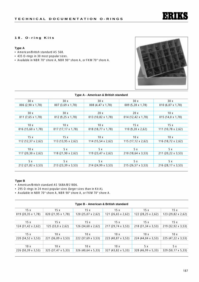
187
T E C H N I C A L D O C U M E N T A T I O N O - R I N G S
1 8 . O - r i n g K i t s
Type A• American/British standard AS 568. • 435 O-rings in 30 most popular sizes. • Available in NBR 70° shore A, NBR 90° shore A, or FKM 70° shore A.
Type A - American & British standard
30 x 30 x 30 x 30 x 30 x006 (2,90 x 1,78) 007 (3,69 x 1,78) 008 (4,47 x 1,78) 009 (5,28 x 1,78) 010 (6,07 x 1,78)
30 x 30 x 20 x 20 x 10 x011 (7,65 x 1,78) 012 (9,25 x 1,78) 013 (10,82 x 1,78) 014 (12,42 x 1,78) 015 (14,0 x 1,78)
10 x 10 x 10 x 15 x 15 x016 (15,60 x 1,78) 017 (17,17 x 1,78) 018 (18,77 x 1,78) 110 (9,20 x 2,62) 111 (10,78 x 2,62)
15 x 15 x 10 x 10 x 10 x112 (12,37 x 2,62) 113 (13,95 x 2,62) 114 (15,54 x 2,62) 115 (17,12 x 2,62) 116 (18,72 x 2,62)
10 x 5 x 5 x 5 x 5 x 117 (20,30 x 2,62) 118 (21,90 x 2,62) 119 (23,47 x 2,62) 210 (18,64 x 3,53) 211 (20,22 x 3,53)
5 x 5 x 5 x 5 x 5 x212 (21,82 x 3,53) 213 (23,39 x 3,53) 214 (24,99 x 3,53) 215 (26,57 x 3,53) 216 (28,17 x 3,53)
Type B• American/British standard AS 568A/BS1806. • 295 O-rings in 24 most popular sizes (larger sizes than in Kit A). • Available in NBR 70° shore A, NBR 90° shore A, or FKM 70° shore A.
Type B - American & British standard
15 x 15 x 15 x 15 x 15 x 15 x019 (20,35 x 1,78) 020 (21,95 x 1,78) 120 (25,07 x 2,62) 121 (26,65 x 2,62) 122 (28,25 x 2,62) 123 (29,82 x 2,62)
15 x 15 x 15 x 15 x 15 x 15 x124 (31,42 x 2,62) 125 (33,0 x 2,62) 126 (34,60 x 2,62) 217 (29,74 x 3,53) 218 (31,34 x 3,53) 219 (32,92 x 3,53)
15 x 10 x 10 x 10 x 10 x 10 x 220 (34,52 x 3,53) 221 (36,09 x 3,53) 222 (37,69 x 3,53) 223 (40,87 x 3,53) 224 (44,04 x 3,53) 225 (47,22 x 3,53)
10 x 10 x 10 x 10 x 5 x 5 x226 (50,39 x 3,53) 325 (37,47 x 5,33) 326 (40,64 x 5,33) 327 (43,82 x 5,33) 328 (46,99 x 5,33) 329 (50,17 x 5,33)
188
S E A L I N G E L E M E N T S
Type C - DIN Metric
20 x 20 x 20 x 20 x 20 xOR 4 x 2 OR 6 x 2 OR 8 x 2 OR 10 x 2 OR 12 x 2
20 x 20 x 20 x 20 x 20 xOR 3,3 x 2,4 OR 4,3 x 2,4 OR 5,3 x 2,4 OR 6,3 x 2,4 OR 7,3 x 2,4
20 x 20 x 15 x 15 x 15 xOR 8,3 x 2,4 OR 9,3 x 2,4 OR 10,3 x 2,4 OR 11,3 x 2,4 OR 12,3 x 2,4
15 x 15 x 10 x 10 x 10 xOR 13,3 x 2,4 OR 14,3 x 2,4 OR 15,3 x 2,4 OR 16,3 x 2,4 OR 17,3 x 2,4
10 x 10 x 10 x 10 x 10 xOR 10 x 3 OR 12 x 3 OR 14 x 3 OR 16 x 3 OR 18 x 3
10 x 5 x 5 x 5 x 5 xOR 19,2 x 3 OR 20 x 3 OR 22 x 3 OR 24 x 3 OR 26,2 x 3
Type D - DIN Metric
15 x 15 x 15 x 15 x 15 x 15 xOR 18 x 2 OR 20 x 2 OR 25 x 3 OR 26,2 x 3 OR 28 x 3 OR 29,2 x 3
15 x 15 x 15 x 15 x 15 x 15 xOR 32,2 x 3 OR 34,2 x 3 OR 36,2 x 3 OR 30 x 4 OR 32 x 4 34 x 4
15 x 10 x 10 x 10 x 10 x 10 x OR 35 x 4 OR 38 x 4 OR 40 x 4 OR 42 x 4 OR 45 x 4 OR 46 x 4
10 x 10 x 5 x 5 x 5 x 5 xOR 48 x 4 OR 35 x 5 OR 40 x 5 OR 45 x 5 OR 48 x 5 OR 50 x 5
Type D• Metric standard DIN 3771.• 295 O-rings in the 24 most popular
sizes (larger sizes than Type C).• Available in NBR 70° shore A or FKM
70° shore A.
Type C• Metric standard DIN 3771.• 425 O-rings in the most popular sizes.• Available in NBR 70° shore A or FKM
70° shore A.
1 8 . O - r i n g K i t s
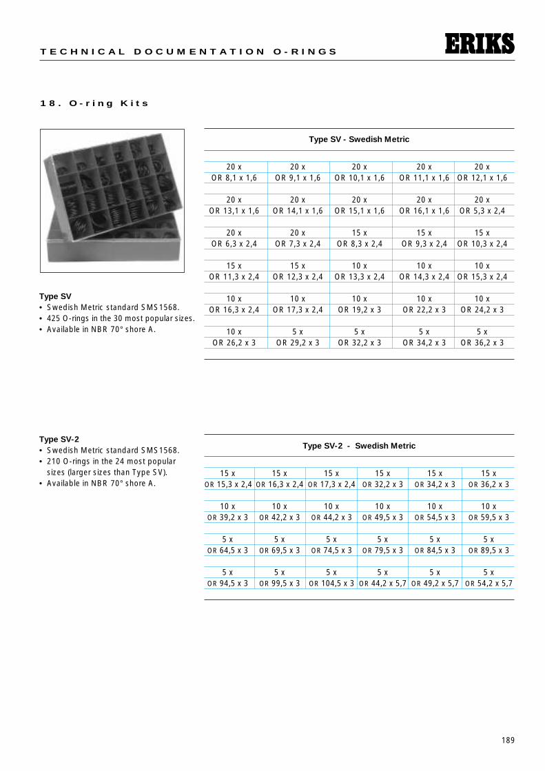
189
T E C H N I C A L D O C U M E N T A T I O N O - R I N G S
1 8 . O - r i n g K i t s
Type SV• Swedish Metric standard SMS1568.• 425 O-rings in the 30 most popular sizes.• Available in NBR 70° shore A.
Type SV - Swedish Metric
20 x 20 x 20 x 20 x 20 xOR 8,1 x 1,6 OR 9,1 x 1,6 OR 10,1 x 1,6 OR 11,1 x 1,6 OR 12,1 x 1,6
20 x 20 x 20 x 20 x 20 xOR 13,1 x 1,6 OR 14,1 x 1,6 OR 15,1 x 1,6 OR 16,1 x 1,6 OR 5,3 x 2,4
20 x 20 x 15 x 15 x 15 xOR 6,3 x 2,4 OR 7,3 x 2,4 OR 8,3 x 2,4 OR 9,3 x 2,4 OR 10,3 x 2,4
15 x 15 x 10 x 10 x 10 xOR 11,3 x 2,4 OR 12,3 x 2,4 OR 13,3 x 2,4 OR 14,3 x 2,4 OR 15,3 x 2,4
10 x 10 x 10 x 10 x 10 xOR 16,3 x 2,4 OR 17,3 x 2,4 OR 19,2 x 3 OR 22,2 x 3 OR 24,2 x 3
10 x 5 x 5 x 5 x 5 xOR 26,2 x 3 OR 29,2 x 3 OR 32,2 x 3 OR 34,2 x 3 OR 36,2 x 3
Type SV-2• Swedish Metric standard SMS1568.• 210 O-rings in the 24 most popular
sizes (larger sizes than Type SV).• Available in NBR 70° shore A.
Type SV-2 - Swedish Metric
15 x 15 x 15 x 15 x 15 x 15 xOR 15,3 x 2,4 OR 16,3 x 2,4 OR 17,3 x 2,4 OR 32,2 x 3 OR 34,2 x 3 OR 36,2 x 3
10 x 10 x 10 x 10 x 10 x 10 xOR 39,2 x 3 OR 42,2 x 3 OR 44,2 x 3 OR 49,5 x 3 OR 54,5 x 3 OR 59,5 x 3
5 x 5 x 5 x 5 x 5 x 5 xOR 64,5 x 3 OR 69,5 x 3 OR 74,5 x 3 OR 79,5 x 3 OR 84,5 x 3 OR 89,5 x 3
5 x 5 x 5 x 5 x 5 x 5 xOR 94,5 x 3 OR 99,5 x 3 OR 104,5 x 3 OR 44,2 x 5,7 OR 49,2 x 5,7 OR 54,2 x 5,7
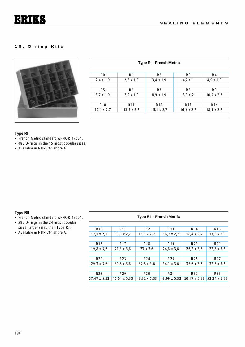
190
S E A L I N G E L E M E N T S
1 8 . O - r i n g K i t s
Type RI• French Metric standard AFNOR 47501.• 485 O-rings in the 15 most popular sizes.• Available in NBR 70° shore A.
Type RII• French Metric standard AFNOR 47501.• 295 O-rings in the 24 most popular
sizes (larger sizes than Type RI).• Available in NBR 70° shore A.
Type RI - French Metric
R0 R1 R2 R3 R42,4 x 1,9 2,6 x 1,9 3,4 x 1,9 4,2 x 1 4,9 x 1,9
R5 R6 R7 R8 R95,7 x 1,9 7,2 x 1,9 8,9 x 1,9 8,9 x 2 10,5 x 2,7
R10 R11 R12 R13 R1412,1 x 2,7 13,6 x 2,7 15,1 x 2,7 16,9 x 2,7 18,4 x 2,7
Type RII - French Metric
R10 R11 R12 R13 R14 R1512,1 x 2,7 13,6 x 2,7 15,1 x 2,7 16,9 x 2,7 18,4 x 2,7 18,3 x 3,6
R16 R17 R18 R19 R20 R2119,8 x 3,6 21,3 x 3,6 23 x 3,6 24,6 x 3,6 26,2 x 3,6 27,8 x 3,6
R22 R23 R24 R25 R26 R2729,3 x 3,6 30,8 x 3,6 32,5 x 3,6 34,1 x 3,6 35,6 x 3,6 37,3 x 3,6
R28 R29 R30 R31 R32 R3337,47 x 5,33 40,64 x 5,33 43,82 x 5,33 46,99 x 5,33 50,17 x 5,33 53,34 x 5,33
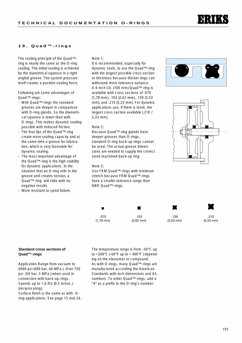
191
T E C H N I C A L D O C U M E N T A T I O N O - R I N G S
1 9 . Q u a d ™ - r i n g s
The sealing principle of the Quad™-ring is nearly the same as the O-ringsealing. The initial sealing is achievedby the diametrical squeeze in a rightangled groove. The system pressureitself creates a positive sealing force.
Following are some advantages of Quad™-rings:- With Quad™-rings the standard
grooves are deeper in comparisonwith O-ring glands. So the diametri-cal squeeze is lower than with O-rings. This makes dynamic sealingpossible with reduced friction.
- The four lips of the Quad™-ring create more sealing capacity and atthe same time a groove for lubrica-tion, which is very favorable fordynamic sealing.
- The most important advantage ofthe Quad™-ring is the high stabilityfor dynamic applications. In the situation that an O-ring rolls in thegroove and creates torsion, aQuad™-ring will slide with no negative results.
- More resistant to spiral failure.
Note 1:It is recommended, especially fordynamic seals, to use the Quad™-ringwith the largest possible cross sectionor thickness because thicker rings canwithstand more tolerance variance.A 4-inch I.D. (100 mm) Quad™-ring isavailable with cross sections of .070(1,78 mm), .103 (2,62 mm), .139 (3,53mm), and .210 (5,33 mm). For dynamicapplications use, if there is room, thelargest cross section available (.210 /5,33 mm).
Note 2:Because Quad™-ring glands have deeper grooves than O-rings, standard O-ring back-up rings cannotbe used. The actual groove dimen-sions are needed to supply the correctsized machined back-up ring.
Note 3: Use FKM Quad™-rings with minimumstretch because FKM Quad™-ringshave a smaller tolerance range thanNBR Quad™-rings.
Standard cross sections of Quad™-rings
Application Range from vacuum to6000 psi (400 bar, 40 MPa.). Over 750psi (50 bar, 5 MPa.) when used inconnection with back-up-rings.Speeds up to 1.6 ft/s (0.5 m/sec.) (reciprocating).Surface finish is the same as with O-ring applications. See page 15 and 24.
The temperature range is from -50°C upto +200°C (-60°F up to + 400°F ) depend-ing on the elastomer or compound. As with O-rings, many Quad™-rings aremanufactured according the AmericanStandards with inch dimensions and AS.numbers. To order Quad™-rings, add a"4" as a prefix to the O-ring’s number.
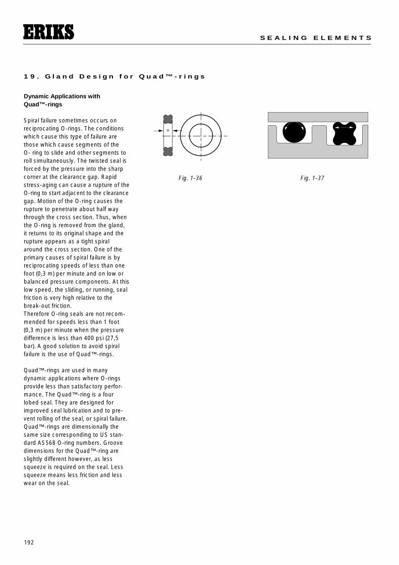
192
S E A L I N G E L E M E N T S
1 9 . G l a n d D e s i g n f o r Q u a d ™ - r i n g s
Dynamic Applications with Quad™-rings
Spiral failure sometimes occurs on reciprocating O-rings. The conditionswhich cause this type of failure arethose which cause segments of the O- ring to slide and other segments toroll simultaneously. The twisted seal isforced by the pressure into the sharpcorner at the clearance gap. Rapidstress-aging can cause a rupture of theO-ring to start adjacent to the clearancegap. Motion of the O-ring causes therupture to penetrate about half waythrough the cross section. Thus, whenthe O-ring is removed from the gland,it returns to its original shape and therupture appears as a tight spiralaround the cross section. One of theprimary causes of spiral failure is byreciprocating speeds of less than onefoot (0,3 m) per minute and on low orbalanced pressure components. At thislow speed, the sliding, or running, sealfriction is very high relative to thebreak-out friction. Therefore O-ring seals are not recom-mended for speeds less than 1 foot(0,3 m) per minute when the pressuredifference is less than 400 psi (27,5bar). A good solution to avoid spiralfailure is the use of Quad™-rings.
Quad™-rings are used in manydynamic applications where O-ringsprovide less than satisfactory perfor-mance. The Quad™-ring is a fourlobed seal. They are designed forimproved seal lubrication and to pre-vent rolling of the seal, or spiral failure. Quad™-rings are dimensionally thesame size corresponding to US stan-dard AS568 O-ring numbers. Groovedimensions for the Quad™-ring areslightly different however, as lesssqueeze is required on the seal. Lesssqueeze means less friction and lesswear on the seal.
W
Fig. 1-36 Fig. 1-37
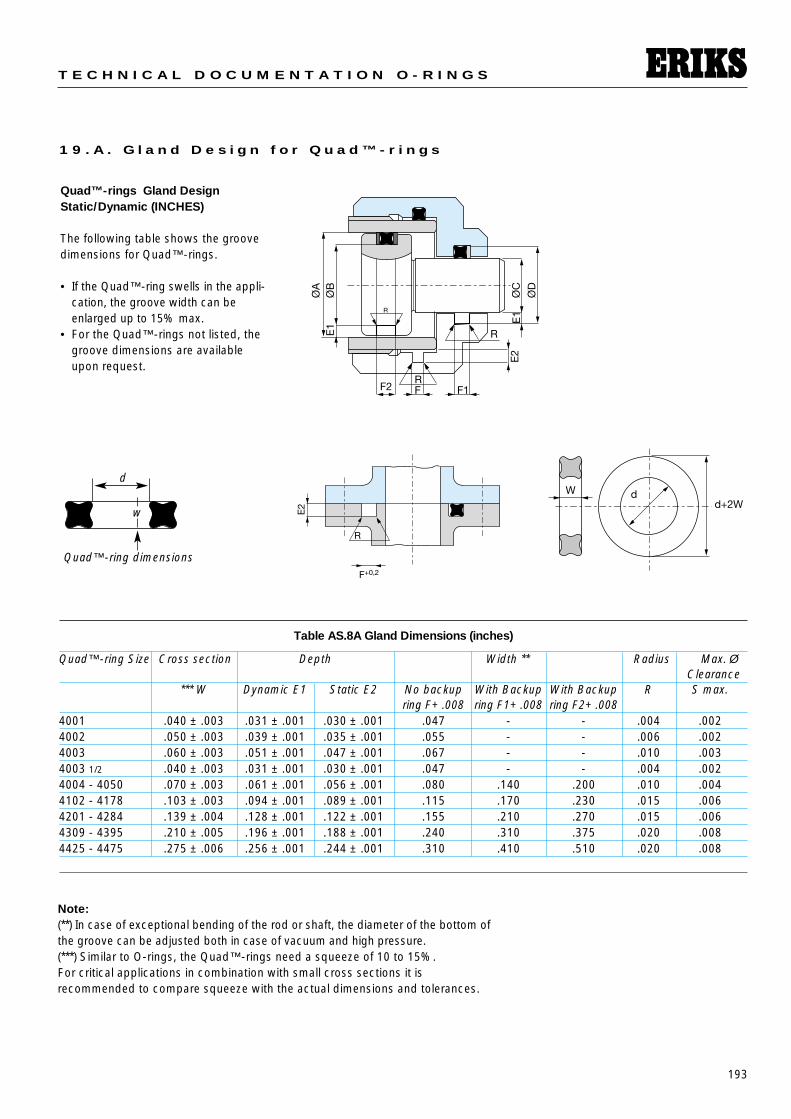
193
T E C H N I C A L D O C U M E N T A T I O N O - R I N G S
1 9 . A . G l a n d D e s i g n f o r Q u a d ™ - r i n g s
Quad™-rings Gland DesignStatic/Dynamic (INCHES)
The following table shows the groovedimensions for Quad™-rings.
• If the Quad™-ring swells in the appli-cation, the groove width can beenlarged up to 15% max.
• For the Quad™-rings not listed, thegroove dimensions are availableupon request.
Table AS.8A Gland Dimensions (inches)
Quad™-ring Size Cross section Depth Width ** Radius Max. ØClearance
*** W Dynamic E1 Static E2 No backup With Backup With Backup R S max.ring F+ .008 ring F1+ .008 ring F2+ .008
4001 .040 ± .003 .031 ± .001 .030 ± .001 .047 - - .004 .0024002 .050 ± .003 .039 ± .001 .035 ± .001 .055 - - .006 .0024003 .060 ± .003 .051 ± .001 .047 ± .001 .067 - - .010 .0034003 1/2 .040 ± .003 .031 ± .001 .030 ± .001 .047 - - .004 .0024004 - 4050 .070 ± .003 .061 ± .001 .056 ± .001 .080 .140 .200 .010 .0044102 - 4178 .103 ± .003 .094 ± .001 .089 ± .001 .115 .170 .230 .015 .0064201 - 4284 .139 ± .004 .128 ± .001 .122 ± .001 .155 .210 .270 .015 .0064309 - 4395 .210 ± .005 .196 ± .001 .188 ± .001 .240 .310 .375 .020 .0084425 - 4475 .275 ± .006 .256 ± .001 .244 ± .001 .310 .410 .510 .020 .008
d
w
Quad™-ring dimensions
Note:(**) In case of exceptional bending of the rod or shaft, the diameter of the bottom ofthe groove can be adjusted both in case of vacuum and high pressure.(***) Similar to O-rings, the Quad™-rings need a squeeze of 10 to 15%. For critical applications in combination with small cross sections it is recommended to compare squeeze with the actual dimensions and tolerances.
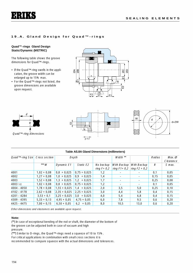
194
S E A L I N G E L E M E N T S
1 9 . A . G l a n d D e s i g n f o r Q u a d ™ - r i n g s
Quad™-rings Gland DesignStatic/Dynamic (METRIC)
The following table shows the groovedimensions for Quad™-rings.
• If the Quad™-ring swells in the appli-cation, the groove width can be enlarged up to 15% max.
• For the Quad™-rings not listed, thegroove dimensions are availableupon request.
Table AS.8A Gland Dimensions (millimeters)
Quad™-ring Size Cross section Depth Width ** Radius Max. ØClearance
*** W Dynamic E1 Static E2 No backup With Backup With Backup R S max.ring F+ 0,2 ring F1+ 0,2 ring F2 + 0,2
4001 1,02 + 0,08 0,8 + 0,025 0,75 + 0,025 1,2 - - 0,1 0,054002 1,27 + 0,08 1,0 + 0,025 0,9 + 0,025 1,4 - - 0,15 0,054003 1,52 + 0,08 1,3 + 0,025 1,2 + 0,025 1,7 - - 0,25 0,084003 1/2 1,02 + 0,08 0,8 + 0,025 0,75 + 0,025 1,2 - - 0,1 0,054004 - 4050 1,78 + 0,08 1,55 + 0,025 1,4 + 0,025 2,0 3,5 5,0 0,25 0,104102 - 4178 2,62 + 0,08 2,35 + 0,025 2,25 + 0,025 3,0 4,4 5,8 0,4 0,154201 - 4284 3,53 + 0,1 3,25 + 0,025 3,0 + 0,025 4,0 5,4 6,8 0,4 0,154309 - 4395 5,33 + 0,13 4,95 + 0,05 4,75 + 0,05 6,0 7,8 9,5 0,6 0,204425 - 4475 7,00 + 0,15 6,50 + 0,05 6,2 + 0,05 8,0 10,5 13,0 0,6 0,20
Other dimensions and elastomers are available upon request.
d
w
Quad™-ring dimensions
Note:(**) In case of exceptional bending of the rod or shaft, the diameter of the bottom ofthe groove can be adjusted both in case of vacuum and high pressure.(***) Similar to O-rings, the Quad™-rings need a squeeze of 10 to 15%. For critical applications in combination with small cross sections it is recommended to compare squeeze with the actual dimensions and tolerances.
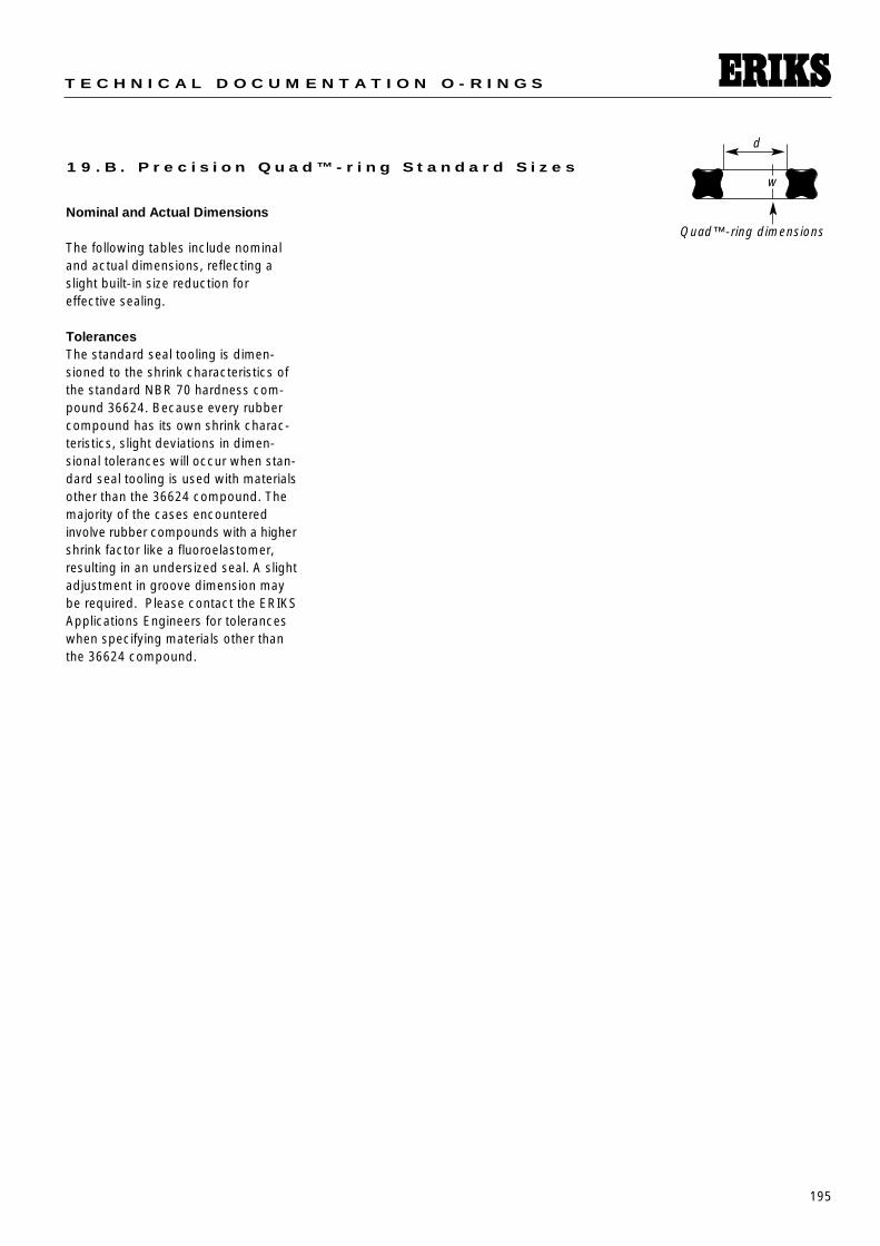
195
T E C H N I C A L D O C U M E N T A T I O N O - R I N G S
1 9 . B . P r e c i s i o n Q u a d ™ - r i n g S t a n d a r d S i z e s
d
w
Quad™-ring dimensionsNominal and Actual Dimensions
The following tables include nominaland actual dimensions, reflecting aslight built-in size reduction for effective sealing.
TolerancesThe standard seal tooling is dimen-sioned to the shrink characteristics ofthe standard NBR 70 hardness com-pound 36624. Because every rubbercompound has its own shrink charac-teristics, slight deviations in dimen-sional tolerances will occur when stan-dard seal tooling is used with materialsother than the 36624 compound. Themajority of the cases encounteredinvolve rubber compounds with a highershrink factor like a fluoroelastomer,resulting in an undersized seal. A slightadjustment in groove dimension maybe required. Please contact the ERIKSApplications Engineers for toleranceswhen specifying materials other thanthe 36624 compound.
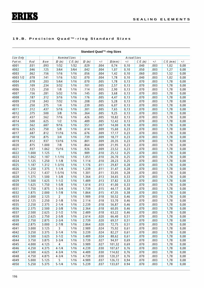
196
S E A L I N G E L E M E N T S
1 9 . B . P r e c i s i o n Q u a d ™ - r i n g S t a n d a r d S i z e s
Standard Quad™-ring Sizes
Size Only Nominal Sizes Actual SizesPart nr. Rod Bore ID (in) C/S (in) ID (in) +/- ID(mm) +/- C/S (in) +/- C/S (mm) +/-4001 .031 .093 1/32 1/32 .029 .004 0,74 0,10 .040 .003 1,02 0,084002 .046 .125 3/64 3/64 .042 .004 1,07 0,10 .050 .003 1,27 0,084003 .062 .156 1/16 1/16 .056 .004 1,42 0,10 .060 .003 1,52 0,084003 1/2 .078 .141 1/16 1/32 .070 .004 1,78 0,10 .040 .003 1,02 0,084004 .078 .203 5/64 1/16 .070 .005 1,78 0,13 .070 .003 1,78 0,084005 .109 .234 3/32 1/16 .101 .005 2,57 0,13 .070 .003 1,78 0,084006 .125 .250 1/8 1/16 .114 .005 2,90 0,13 .070 .003 1,78 0,084007 .156 .281 5/32 1/16 .145 .005 3,68 0,13 .070 .003 1,78 0,084008 .187 .312 3/16 1/16 .176 .005 4,47 0,13 .070 .003 1,78 0,084009 .218 .343 7/32 1/16 .208 .005 5,28 0,13 .070 .003 1,78 0,084010 .250 .375 1/4 1/16 .239 .005 6,07 0,13 .070 .003 1,78 0,084011 .312 .437 5/16 1/16 .301 .005 7,65 0,13 .070 .003 1,78 0,084012 .375 .500 3/8 1/16 .364 .005 9,25 0,13 .070 .003 1,78 0,084013 .437 .562 7/16 1/16 .426 .005 10,82 0,13 .070 .003 1,78 0,084014 .500 .625 1/2 1/16 .489 .005 12,42 0,13 .070 .003 1,78 0,084015 .562 .687 9/16 1/16 .551 .007 14,00 0,18 .070 .003 1,78 0,084016 .625 .750 5/8 1/16 .614 .009 15,60 0,23 .070 .003 1,78 0,084017 .687 .812 11/16 1/16 .676 .009 17,17 0,23 .070 .003 1,78 0,084018 .750 .875 3/4 1/16 .739 .009 18,77 0,23 .070 .003 1,78 0,084019 .812 .937 13/16 1/16 .801 .009 20,35 0,23 .070 .003 1,78 0,084020 .875 1.000 7/8 1/16 .864 .009 21,95 0,23 .070 .003 1,78 0,084021 .937 1.062 15/16 1/16 .926 .009 23,52 0,23 .070 .003 1,78 0,084022 1.000 1.125 1 1/16 .989 .010 25,12 0,25 .070 .003 1,78 0,084023 1.062 1.187 1-1/16 1/16 1.051 .010 26,70 0,25 .070 .003 1,78 0,084024 1.125 1.250 1-1/8 1/16 1.114 .010 28,23 0,25 .070 .003 1,78 0,084025 1.187 1.312 1-3/16 1/16 1.176 .011 29,87 0,28 .070 .003 1,78 0,084026 1.250 1.375 1-1/4 1/16 1.239 .011 31,47 0,28 .070 .003 1,78 0,084027 1.312 1.437 1-5/16 1/16 1.301 .011 33,05 0,28 .070 .003 1,78 0,084028 1.375 1.500 1-3/8 1/16 1.364 .013 34,65 0,33 .070 .003 1,78 0,084029 1.500 1.625 1-1/2 1/16 1.489 .013 37,82 0,33 .070 .003 1,78 0,084030 1.625 1.750 1-5/8 1/16 1.614 .013 41,00 0,33 .070 .003 1,78 0,084031 1.750 1.875 1-3/4 1/16 1.739 .015 44,17 0,38 .070 .003 1,78 0,084032 1.875 2.000 1-7/8 1/16 1.864 .015 47,35 0,38 .070 .003 1,78 0,084033 2.000 2.125 2 1/16 1.989 .018 50,52 0,46 .070 .003 1,78 0,084034 2.125 2.250 2-1/8 1/16 2.114 .018 53,70 0,46 .070 .003 1,78 0,084035 2.250 2.375 2-1/4 1/16 2.239 .018 56,87 0,46 .070 .003 1,78 0,084036 2.375 2.500 2-3/8 1/16 2.364 .018 60,05 0,46 .070 .003 1,78 0,084037 2.500 2.625 2-1/2 1/16 2.489 .018 63,22 0,46 .070 .003 1,78 0,084038 2.625 2.750 2-5/8 1/16 2.614 .020 66,40 0,51 .070 .003 1,78 0,084039 2.750 2.875 2-3/4 1/16 2.739 .020 69,57 0,51 .070 .003 1,78 0,084040 2.875 3.000 2-7/8 1/16 2.864 .020 72,75 0,51 .070 .003 1,78 0,084041 3.000 3.125 3 1/16 2.989 .024 75,92 0,61 .070 .003 1,78 0,084042 3.250 3.375 3-1/4 1/16 3.239 .024 82,27 0,61 .070 .003 1,78 0,084043 3.500 3.625 3-1/2 1/16 3.489 .024 88,62 0,61 .070 .003 1,78 0,084044 3.750 3.875 3-3/4 1/16 3.739 .027 94,97 0,69 .070 .003 1,78 0,084045 4.000 4.125 4 1/16 3.989 .027 101,32 0,69 .070 .003 1,78 0,084046 4.250 4.375 4-1/4 1/16 4.239 .030 107,67 0,76 .070 .003 1,78 0,084047 4.500 4.625 4-3/4 1/16 4.489 .030 114,02 0,76 .070 .003 1,78 0,084048 4.750 4.875 4-3/4 1/16 4.739 .030 120,37 0,76 .070 .003 1,78 0,084049 5.000 5.125 5 1/16 4.989 .037 126,72 0,94 .070 .003 1,78 0,084050 5.250 5.375 5-1/4 1/16 5.239 .037 133,07 0.94 .070 .003 1,78 0,08
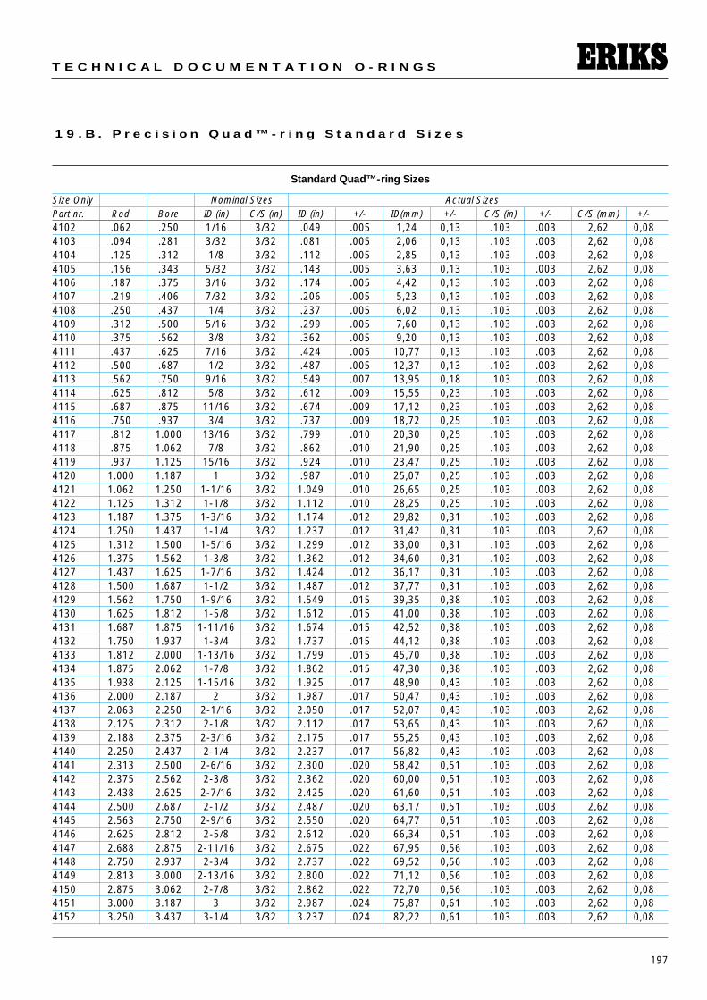
197
T E C H N I C A L D O C U M E N T A T I O N O - R I N G S
1 9 . B . P r e c i s i o n Q u a d ™ - r i n g S t a n d a r d S i z e s
Standard Quad™-ring Sizes
Size Only Nominal Sizes Actual SizesPart nr. Rod Bore ID (in) C/S (in) ID (in) +/- ID(mm) +/- C/S (in) +/- C/S (mm) +/-4102 .062 .250 1/16 3/32 .049 .005 1,24 0,13 .103 .003 2,62 0,084103 .094 .281 3/32 3/32 .081 .005 2,06 0,13 .103 .003 2,62 0,084104 .125 .312 1/8 3/32 .112 .005 2,85 0,13 .103 .003 2,62 0,084105 .156 .343 5/32 3/32 .143 .005 3,63 0,13 .103 .003 2,62 0,084106 .187 .375 3/16 3/32 .174 .005 4,42 0,13 .103 .003 2,62 0,084107 .219 .406 7/32 3/32 .206 .005 5,23 0,13 .103 .003 2,62 0,084108 .250 .437 1/4 3/32 .237 .005 6,02 0,13 .103 .003 2,62 0,084109 .312 .500 5/16 3/32 .299 .005 7,60 0,13 .103 .003 2,62 0,084110 .375 .562 3/8 3/32 .362 .005 9,20 0,13 .103 .003 2,62 0,084111 .437 .625 7/16 3/32 .424 .005 10,77 0,13 .103 .003 2,62 0,084112 .500 .687 1/2 3/32 .487 .005 12,37 0,13 .103 .003 2,62 0,084113 .562 .750 9/16 3/32 .549 .007 13,95 0,18 .103 .003 2,62 0,084114 .625 .812 5/8 3/32 .612 .009 15,55 0,23 .103 .003 2,62 0,084115 .687 .875 11/16 3/32 .674 .009 17,12 0,23 .103 .003 2,62 0,084116 .750 .937 3/4 3/32 .737 .009 18,72 0,25 .103 .003 2,62 0,084117 .812 1.000 13/16 3/32 .799 .010 20,30 0,25 .103 .003 2,62 0,084118 .875 1.062 7/8 3/32 .862 .010 21,90 0,25 .103 .003 2,62 0,084119 .937 1.125 15/16 3/32 .924 .010 23,47 0,25 .103 .003 2,62 0,084120 1.000 1.187 1 3/32 .987 .010 25,07 0,25 .103 .003 2,62 0,084121 1.062 1.250 1-1/16 3/32 1.049 .010 26,65 0,25 .103 .003 2,62 0,084122 1.125 1.312 1-1/8 3/32 1.112 .010 28,25 0,25 .103 .003 2,62 0,084123 1.187 1.375 1-3/16 3/32 1.174 .012 29,82 0,31 .103 .003 2,62 0,084124 1.250 1.437 1-1/4 3/32 1.237 .012 31,42 0,31 .103 .003 2,62 0,084125 1.312 1.500 1-5/16 3/32 1.299 .012 33,00 0,31 .103 .003 2,62 0,084126 1.375 1.562 1-3/8 3/32 1.362 .012 34,60 0,31 .103 .003 2,62 0,084127 1.437 1.625 1-7/16 3/32 1.424 .012 36,17 0,31 .103 .003 2,62 0,084128 1.500 1.687 1-1/2 3/32 1.487 .012 37,77 0,31 .103 .003 2,62 0,084129 1.562 1.750 1-9/16 3/32 1.549 .015 39,35 0,38 .103 .003 2,62 0,084130 1.625 1.812 1-5/8 3/32 1.612 .015 41,00 0,38 .103 .003 2,62 0,084131 1.687 1.875 1-11/16 3/32 1.674 .015 42,52 0,38 .103 .003 2,62 0,084132 1.750 1.937 1-3/4 3/32 1.737 .015 44,12 0,38 .103 .003 2,62 0,084133 1.812 2.000 1-13/16 3/32 1.799 .015 45,70 0,38 .103 .003 2,62 0,084134 1.875 2.062 1-7/8 3/32 1.862 .015 47,30 0,38 .103 .003 2,62 0,084135 1.938 2.125 1-15/16 3/32 1.925 .017 48,90 0,43 .103 .003 2,62 0,084136 2.000 2.187 2 3/32 1.987 .017 50,47 0,43 .103 .003 2,62 0,084137 2.063 2.250 2-1/16 3/32 2.050 .017 52,07 0,43 .103 .003 2,62 0,084138 2.125 2.312 2-1/8 3/32 2.112 .017 53,65 0,43 .103 .003 2,62 0,084139 2.188 2.375 2-3/16 3/32 2.175 .017 55,25 0,43 .103 .003 2,62 0,084140 2.250 2.437 2-1/4 3/32 2.237 .017 56,82 0,43 .103 .003 2,62 0,084141 2.313 2.500 2-6/16 3/32 2.300 .020 58,42 0,51 .103 .003 2,62 0,084142 2.375 2.562 2-3/8 3/32 2.362 .020 60,00 0,51 .103 .003 2,62 0,084143 2.438 2.625 2-7/16 3/32 2.425 .020 61,60 0,51 .103 .003 2,62 0,084144 2.500 2.687 2-1/2 3/32 2.487 .020 63,17 0,51 .103 .003 2,62 0,084145 2.563 2.750 2-9/16 3/32 2.550 .020 64,77 0,51 .103 .003 2,62 0,084146 2.625 2.812 2-5/8 3/32 2.612 .020 66,34 0,51 .103 .003 2,62 0,084147 2.688 2.875 2-11/16 3/32 2.675 .022 67,95 0,56 .103 .003 2,62 0,084148 2.750 2.937 2-3/4 3/32 2.737 .022 69,52 0,56 .103 .003 2,62 0,084149 2.813 3.000 2-13/16 3/32 2.800 .022 71,12 0,56 .103 .003 2,62 0,084150 2.875 3.062 2-7/8 3/32 2.862 .022 72,70 0,56 .103 .003 2,62 0,084151 3.000 3.187 3 3/32 2.987 .024 75,87 0,61 .103 .003 2,62 0,084152 3.250 3.437 3-1/4 3/32 3.237 .024 82,22 0,61 .103 .003 2,62 0,08
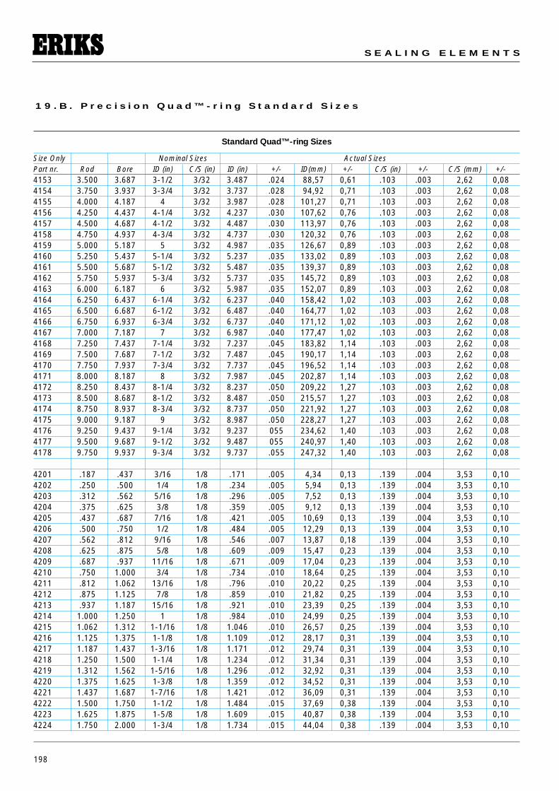
198
S E A L I N G E L E M E N T S
1 9 . B . P r e c i s i o n Q u a d ™ - r i n g S t a n d a r d S i z e s
Standard Quad™-ring Sizes
Size Only Nominal Sizes Actual SizesPart nr. Rod Bore ID (in) C/S (in) ID (in) +/- ID(mm) +/- C/S (in) +/- C/S (mm) +/-4153 3.500 3.687 3-1/2 3/32 3.487 .024 88,57 0,61 .103 .003 2,62 0,084154 3.750 3.937 3-3/4 3/32 3.737 .028 94,92 0,71 .103 .003 2,62 0,084155 4.000 4.187 4 3/32 3.987 .028 101,27 0,71 .103 .003 2,62 0,084156 4.250 4.437 4-1/4 3/32 4.237 .030 107,62 0,76 .103 .003 2,62 0,084157 4.500 4.687 4-1/2 3/32 4.487 .030 113,97 0,76 .103 .003 2,62 0,084158 4.750 4.937 4-3/4 3/32 4.737 .030 120,32 0,76 .103 .003 2,62 0,084159 5.000 5.187 5 3/32 4.987 .035 126,67 0,89 .103 .003 2,62 0,084160 5.250 5.437 5-1/4 3/32 5.237 .035 133,02 0,89 .103 .003 2,62 0,084161 5.500 5.687 5-1/2 3/32 5.487 .035 139,37 0,89 .103 .003 2,62 0,084162 5.750 5.937 5-3/4 3/32 5.737 .035 145,72 0,89 .103 .003 2,62 0,084163 6.000 6.187 6 3/32 5.987 .035 152,07 0,89 .103 .003 2,62 0,084164 6.250 6.437 6-1/4 3/32 6.237 .040 158,42 1,02 .103 .003 2,62 0,084165 6.500 6.687 6-1/2 3/32 6.487 .040 164,77 1,02 .103 .003 2,62 0,084166 6.750 6.937 6-3/4 3/32 6.737 .040 171,12 1,02 .103 .003 2,62 0,084167 7.000 7.187 7 3/32 6.987 .040 177,47 1,02 .103 .003 2,62 0,084168 7.250 7.437 7-1/4 3/32 7.237 .045 183,82 1,14 .103 .003 2,62 0,084169 7.500 7.687 7-1/2 3/32 7.487 .045 190,17 1,14 .103 .003 2,62 0,084170 7.750 7.937 7-3/4 3/32 7.737 .045 196,52 1,14 .103 .003 2,62 0,084171 8.000 8.187 8 3/32 7.987 .045 202,87 1,14 .103 .003 2,62 0,084172 8.250 8.437 8-1/4 3/32 8.237 .050 209,22 1,27 .103 .003 2,62 0,084173 8.500 8.687 8-1/2 3/32 8.487 .050 215,57 1,27 .103 .003 2,62 0,084174 8.750 8.937 8-3/4 3/32 8.737 .050 221,92 1,27 .103 .003 2,62 0,084175 9.000 9.187 9 3/32 8.987 .050 228,27 1,27 .103 .003 2,62 0,084176 9.250 9.437 9-1/4 3/32 9.237 055 234,62 1,40 .103 .003 2,62 0,084177 9.500 9.687 9-1/2 3/32 9.487 055 240,97 1,40 .103 .003 2,62 0,084178 9.750 9.937 9-3/4 3/32 9.737 .055 247,32 1,40 .103 .003 2,62 0,08
4201 .187 .437 3/16 1/8 .171 .005 4,34 0,13 .139 .004 3,53 0,104202 .250 .500 1/4 1/8 .234 .005 5,94 0,13 .139 .004 3,53 0,104203 .312 .562 5/16 1/8 .296 .005 7,52 0,13 .139 .004 3,53 0,104204 .375 .625 3/8 1/8 .359 .005 9,12 0,13 .139 .004 3,53 0,104205 .437 .687 7/16 1/8 .421 .005 10,69 0,13 .139 .004 3,53 0,104206 .500 .750 1/2 1/8 .484 .005 12,29 0,13 .139 .004 3,53 0,104207 .562 .812 9/16 1/8 .546 .007 13,87 0,18 .139 .004 3,53 0,104208 .625 .875 5/8 1/8 .609 .009 15,47 0,23 .139 .004 3,53 0,104209 .687 .937 11/16 1/8 .671 .009 17,04 0,23 .139 .004 3,53 0,104210 .750 1.000 3/4 1/8 .734 .010 18,64 0,25 .139 .004 3,53 0,104211 .812 1.062 13/16 1/8 .796 .010 20,22 0,25 .139 .004 3,53 0,104212 .875 1.125 7/8 1/8 .859 .010 21,82 0,25 .139 .004 3,53 0,104213 .937 1.187 15/16 1/8 .921 .010 23,39 0,25 .139 .004 3,53 0,104214 1.000 1.250 1 1/8 .984 .010 24,99 0,25 .139 .004 3,53 0,104215 1.062 1.312 1-1/16 1/8 1.046 .010 26,57 0,25 .139 .004 3,53 0,104216 1.125 1.375 1-1/8 1/8 1.109 .012 28,17 0,31 .139 .004 3,53 0,104217 1.187 1.437 1-3/16 1/8 1.171 .012 29,74 0,31 .139 .004 3,53 0,104218 1.250 1.500 1-1/4 1/8 1.234 .012 31,34 0,31 .139 .004 3,53 0,104219 1.312 1.562 1-5/16 1/8 1.296 .012 32,92 0,31 .139 .004 3,53 0,104220 1.375 1.625 1-3/8 1/8 1.359 .012 34,52 0,31 .139 .004 3,53 0,104221 1.437 1.687 1-7/16 1/8 1.421 .012 36,09 0,31 .139 .004 3,53 0,104222 1.500 1.750 1-1/2 1/8 1.484 .015 37,69 0,38 .139 .004 3,53 0,104223 1.625 1.875 1-5/8 1/8 1.609 .015 40,87 0,38 .139 .004 3,53 0,104224 1.750 2.000 1-3/4 1/8 1.734 .015 44,04 0,38 .139 .004 3,53 0,10
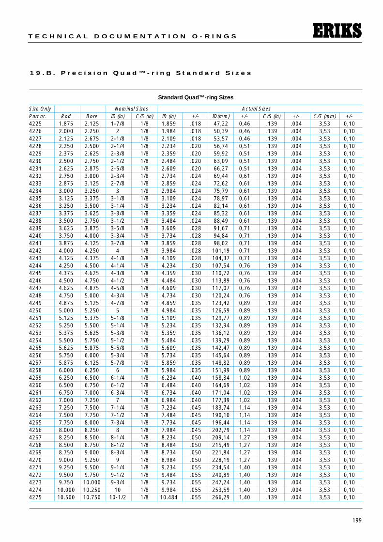
199
T E C H N I C A L D O C U M E N T A T I O N O - R I N G S
1 9 . B . P r e c i s i o n Q u a d ™ - r i n g S t a n d a r d S i z e s
Standard Quad™-ring Sizes
Size Only Nominal Sizes Actual SizesPart nr. Rod Bore ID (in) C/S (in) ID (in) +/- ID(mm) +/- C/S (in) +/- C/S (mm) +/-4225 1.875 2.125 1-7/8 1/8 1.859 .018 47,22 0,46 .139 .004 3,53 0,104226 2.000 2.250 2 1/8 1.984 .018 50,39 0,46 .139 .004 3,53 0,104227 2.125 2.675 2-1/8 1/8 2.109 .018 53,57 0,46 .139 .004 3,53 0,104228 2.250 2.500 2-1/4 1/8 2.234 .020 56,74 0,51 .139 .004 3,53 0,104229 2.375 2.625 2-3/8 1/8 2.359 .020 59,92 0,51 .139 .004 3,53 0,104230 2.500 2.750 2-1/2 1/8 2.484 .020 63,09 0,51 .139 .004 3,53 0,104231 2.625 2.875 2-5/8 1/8 2.609 .020 66,27 0,51 .139 .004 3,53 0,104232 2.750 3.000 2-3/4 1/8 2.734 .024 69,44 0,61 .139 .004 3,53 0,104233 2.875 3.125 2-7/8 1/8 2.859 .024 72,62 0,61 .139 .004 3,53 0,104234 3.000 3.250 3 1/8 2.984 .024 75,79 0,61 .139 .004 3,53 0,104235 3.125 3.375 3-1/8 1/8 3.109 .024 78,97 0,61 .139 .004 3,53 0,104236 3.250 3.500 3-1/4 1/8 3.234 .024 82,14 0,61 .139 .004 3,53 0,104237 3.375 3.625 3-3/8 1/8 3.359 .024 85,32 0,61 .139 .004 3,53 0,104238 3.500 2.750 3-1/2 1/8 3.484 .024 88,49 0,61 .139 .004 3,53 0,104239 3.625 3.875 3-5/8 1/8 3.609 .028 91,67 0,71 .139 .004 3,53 0,104240 3.750 4.000 3-3/4 1/8 3.734 .028 94,84 0,71 .139 .004 3,53 0,104241 3.875 4.125 3-7/8 1/8 3.859 .028 98,02 0,71 .139 .004 3,53 0,104242 4.000 4.250 4 1/8 3.984 .028 101,19 0,71 .139 .004 3,53 0,104243 4.125 4.375 4-1/8 1/8 4.109 .028 104,37 0,71 .139 .004 3,53 0,104244 4.250 4.500 4-1/4 1/8 4.234 .030 107,54 0,76 .139 .004 3,53 0,104245 4.375 4.625 4-3/8 1/8 4.359 .030 110,72 0,76 .139 .004 3,53 0,104246 4.500 4.750 4-1/2 1/8 4.484 .030 113,89 0,76 .139 .004 3,53 0,104247 4.625 4.875 4-5/8 1/8 4.609 .030 117,07 0,76 .139 .004 3,53 0,104248 4.750 5.000 4-3/4 1/8 4.734 .030 120,24 0,76 .139 .004 3,53 0,104249 4.875 5.125 4-7/8 1/8 4.859 .035 123,42 0,89 .139 .004 3,53 0,104250 5.000 5.250 5 1/8 4.984 .035 126,59 0,89 .139 .004 3,53 0,104251 5.125 5.375 5-1/8 1/8 5.109 .035 129,77 0,89 .139 .004 3,53 0,104252 5.250 5.500 5-1/4 1/8 5.234 .035 132,94 0,89 .139 .004 3,53 0,104253 5.375 5.625 5-3/8 1/8 5.359 .035 136,12 0,89 .139 .004 3,53 0,104254 5.500 5.750 5-1/2 1/8 5.484 .035 139,29 0,89 .139 .004 3,53 0,104255 5.625 5.875 5-5/8 1/8 5.609 .035 142,47 0,89 .139 .004 3,53 0,104256 5.750 6.000 5-3/4 1/8 5.734 .035 145,64 0,89 .139 .004 3,53 0,104257 5.875 6.125 5-7/8 1/8 5.859 .035 148,82 0,89 .139 .004 3,53 0,104258 6.000 6.250 6 1/8 5.984 .035 151,99 0,89 .139 .004 3,53 0,104259 6.250 6.500 6-1/4 1/8 6.234 .040 158,34 1,02 .139 .004 3,53 0,104260 6.500 6.750 6-1/2 1/8 6.484 .040 164,69 1,02 .139 .004 3,53 0,104261 6.750 7.000 6-3/4 1/8 6.734 .040 171,04 1,02 .139 .004 3,53 0,104262 7.000 7.250 7 1/8 6.984 .040 177,39 1,02 .139 .004 3,53 0,104263 7.250 7.500 7-1/4 1/8 7.234 .045 183,74 1,14 .139 .004 3,53 0,104264 7.500 7.750 7-1/2 1/8 7.484 .045 190,10 1,14 .139 .004 3,53 0,104265 7.750 8.000 7-3/4 1/8 7.734 .045 196,44 1,14 .139 .004 3,53 0,104266 8.000 8.250 8 1/8 7.984 .045 202,79 1,14 .139 .004 3,53 0,104267 8.250 8.500 8-1/4 1/8 8.234 .050 209,14 1,27 .139 .004 3,53 0,104268 8.500 8.750 8-1/2 1/8 8.484 .050 215,49 1,27 .139 .004 3,53 0,104269 8.750 9.000 8-3/4 1/8 8.734 .050 221,84 1,27 .139 .004 3,53 0,104270 9.000 9.250 9 1/8 8.984 .050 228,19 1,27 .139 .004 3,53 0,104271 9.250 9.500 9-1/4 1/8 9.234 .055 234,54 1,40 .139 .004 3,53 0,104272 9.500 9.750 9-1/2 1/8 9.484 .055 240,89 1,40 .139 .004 3,53 0,104273 9.750 10.000 9-3/4 1/8 9.734 .055 247,24 1,40 .139 .004 3,53 0,104274 10.000 10.250 10 1/8 9.984 .055 253,59 1,40 .139 .004 3,53 0,104275 10.500 10.750 10-1/2 1/8 10.484 .055 266,29 1,40 .139 .004 3,53 0,10
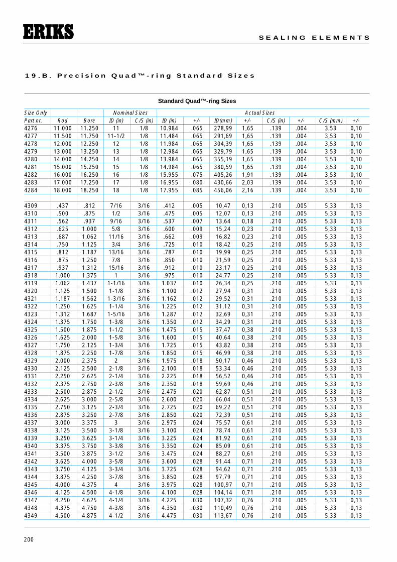
200
S E A L I N G E L E M E N T S
1 9 . B . P r e c i s i o n Q u a d ™ - r i n g S t a n d a r d S i z e s
Standard Quad™-ring Sizes
Size Only Nominal Sizes Actual SizesPart nr. Rod Bore ID (in) C/S (in) ID (in) +/- ID(mm) +/- C/S (in) +/- C/S (mm) +/-4276 11.000 11.250 11 1/8 10.984 .065 278,99 1,65 .139 .004 3,53 0,104277 11.500 11.750 11-1/2 1/8 11.484 .065 291,69 1,65 .139 .004 3,53 0,104278 12.000 12.250 12 1/8 11.984 .065 304,39 1,65 .139 .004 3,53 0,104279 13.000 13.250 13 1/8 12.984 .065 329,79 1,65 .139 .004 3,53 0,104280 14.000 14.250 14 1/8 13.984 .065 355,19 1,65 .139 .004 3,53 0,104281 15.000 15.250 15 1/8 14.984 .065 380,59 1,65 .139 .004 3,53 0,104282 16.000 16.250 16 1/8 15.955 .075 405,26 1,91 .139 .004 3,53 0,104283 17.000 17.250 17 1/8 16.955 .080 430,66 2,03 .139 .004 3,53 0,104284 18.000 18.250 18 1/8 17.955 .085 456,06 2,16 .139 .004 3,53 0,10
4309 .437 .812 7/16 3/16 .412 .005 10,47 0,13 .210 .005 5,33 0,134310 .500 .875 1/2 3/16 .475 .005 12,07 0,13 .210 .005 5,33 0,134311 .562 .937 9/16 3/16 .537 .007 13,64 0,18 .210 .005 5,33 0,134312 .625 1.000 5/8 3/16 .600 .009 15,24 0,23 .210 .005 5,33 0,134313 .687 1.062 11/16 3/16 .662 .009 16,82 0,23 .210 .005 5,33 0,134314 .750 1.125 3/4 3/16 .725 .010 18,42 0,25 .210 .005 5,33 0,134315 .812 1.187 13/16 3/16 .787 .010 19,99 0,25 .210 .005 5,33 0,134316 .875 1.250 7/8 3/16 .850 .010 21,59 0,25 .210 .005 5,33 0,134317 .937 1.312 15/16 3/16 .912 .010 23,17 0,25 .210 .005 5,33 0,134318 1.000 1.375 1 3/16 .975 .010 24,77 0,25 .210 .005 5,33 0,134319 1.062 1.437 1-1/16 3/16 1.037 .010 26,34 0,25 .210 .005 5,33 0,134320 1.125 1.500 1-1/8 3/16 1.100 .012 27,94 0,31 .210 .005 5,33 0,134321 1.187 1.562 1-3/16 3/16 1.162 .012 29,52 0,31 .210 .005 5,33 0,134322 1.250 1.625 1-1/4 3/16 1.225 .012 31,12 0,31 .210 .005 5,33 0,134323 1.312 1.687 1-5/16 3/16 1.287 .012 32,69 0,31 .210 .005 5,33 0,134324 1.375 1.750 1-3/8 3/16 1.350 .012 34,29 0,31 .210 .005 5,33 0,134325 1.500 1.875 1-1/2 3/16 1.475 .015 37,47 0,38 .210 .005 5,33 0,134326 1.625 2.000 1-5/8 3/16 1.600 .015 40,64 0,38 .210 .005 5,33 0,134327 1.750 2.125 1-3/4 3/16 1.725 .015 43,82 0,38 .210 .005 5,33 0,134328 1.875 2.250 1-7/8 3/16 1.850 .015 46,99 0,38 .210 .005 5,33 0,134329 2.000 2.375 2 3/16 1.975 .018 50,17 0,46 .210 .005 5,33 0,134330 2.125 2.500 2-1/8 3/16 2.100 .018 53,34 0,46 .210 .005 5,33 0,134331 2.250 2.625 2-1/4 3/16 2.225 .018 56,52 0,46 .210 .005 5,33 0,134332 2.375 2.750 2-3/8 3/16 2.350 .018 59,69 0,46 .210 .005 5,33 0,134333 2.500 2.875 2-1/2 3/16 2.475 .020 62,87 0,51 .210 .005 5,33 0,134334 2.625 3.000 2-5/8 3/16 2.600 .020 66,04 0,51 .210 .005 5,33 0,134335 2.750 3.125 2-3/4 3/16 2.725 .020 69,22 0,51 .210 .005 5,33 0,134336 2.875 3.250 2-7/8 3/16 2.850 .020 72,39 0,51 .210 .005 5,33 0,134337 3.000 3.375 3 3/16 2.975 .024 75,57 0,61 .210 .005 5,33 0,134338 3.125 3.500 3-1/8 3/16 3.100 .024 78,74 0,61 .210 .005 5,33 0,134339 3.250 3.625 3-1/4 3/16 3.225 .024 81,92 0,61 .210 .005 5,33 0,134340 3.375 3.750 3-3/8 3/16 3.350 .024 85,09 0,61 .210 .005 5,33 0,134341 3.500 3.875 3-1/2 3/16 3.475 .024 88,27 0,61 .210 .005 5,33 0,134342 3.625 4.000 3-5/8 3/16 3.600 .028 91,44 0,71 .210 .005 5,33 0,134343 3.750 4.125 3-3/4 3/16 3.725 .028 94,62 0,71 .210 .005 5,33 0,134344 3.875 4.250 3-7/8 3/16 3.850 .028 97,79 0,71 .210 .005 5,33 0,134345 4.000 4.375 4 3/16 3.975 .028 100,97 0,71 .210 .005 5,33 0,134346 4.125 4.500 4-1/8 3/16 4.100 .028 104,14 0,71 .210 .005 5,33 0,134347 4.250 4.625 4-1/4 3/16 4.225 .030 107,32 0,76 .210 .005 5,33 0,134348 4.375 4.750 4-3/8 3/16 4.350 .030 110,49 0,76 .210 .005 5,33 0,134349 4.500 4.875 4-1/2 3/16 4.475 .030 113,67 0,76 .210 .005 5,33 0,13
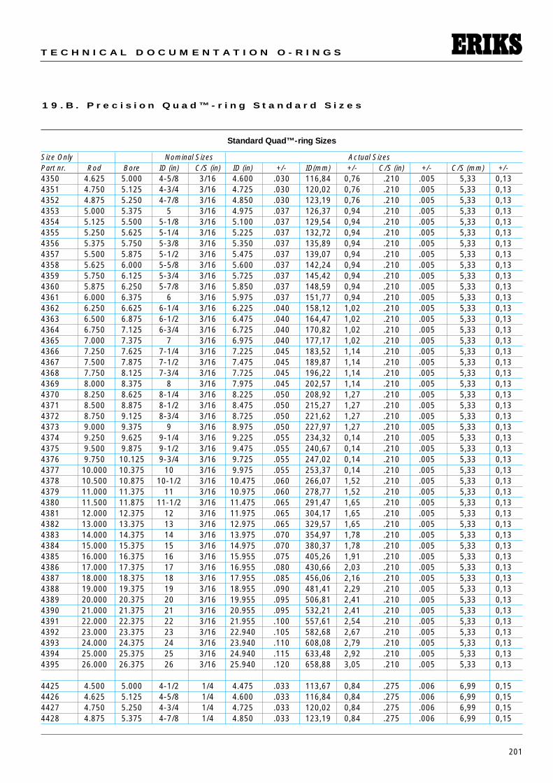
201
T E C H N I C A L D O C U M E N T A T I O N O - R I N G S
1 9 . B . P r e c i s i o n Q u a d ™ - r i n g S t a n d a r d S i z e s
Standard Quad™-ring Sizes
Size Only Nominal Sizes Actual SizesPart nr. Rod Bore ID (in) C/S (in) ID (in) +/- ID(mm) +/- C/S (in) +/- C/S (mm) +/-4350 4.625 5.000 4-5/8 3/16 4.600 .030 116,84 0,76 .210 .005 5,33 0,134351 4.750 5.125 4-3/4 3/16 4.725 .030 120,02 0,76 .210 .005 5,33 0,134352 4.875 5.250 4-7/8 3/16 4.850 .030 123,19 0,76 .210 .005 5,33 0,134353 5.000 5.375 5 3/16 4.975 .037 126,37 0,94 .210 .005 5,33 0,134354 5.125 5.500 5-1/8 3/16 5.100 .037 129,54 0,94 .210 .005 5,33 0,134355 5.250 5.625 5-1/4 3/16 5.225 .037 132,72 0,94 .210 .005 5,33 0,134356 5.375 5.750 5-3/8 3/16 5.350 .037 135,89 0,94 .210 .005 5,33 0,134357 5.500 5.875 5-1/2 3/16 5.475 .037 139,07 0,94 .210 .005 5,33 0,134358 5.625 6.000 5-5/8 3/16 5.600 .037 142,24 0,94 .210 .005 5,33 0,134359 5.750 6.125 5-3/4 3/16 5.725 .037 145,42 0,94 .210 .005 5,33 0,134360 5.875 6.250 5-7/8 3/16 5.850 .037 148,59 0,94 .210 .005 5,33 0,134361 6.000 6.375 6 3/16 5.975 .037 151,77 0,94 .210 .005 5,33 0,134362 6.250 6.625 6-1/4 3/16 6.225 .040 158,12 1,02 .210 .005 5,33 0,134363 6.500 6.875 6-1/2 3/16 6.475 .040 164,47 1,02 .210 .005 5,33 0,134364 6.750 7.125 6-3/4 3/16 6.725 .040 170,82 1,02 .210 .005 5,33 0,134365 7.000 7.375 7 3/16 6.975 .040 177,17 1,02 .210 .005 5,33 0,134366 7.250 7.625 7-1/4 3/16 7.225 .045 183,52 1,14 .210 .005 5,33 0,134367 7.500 7.875 7-1/2 3/16 7.475 .045 189,87 1,14 .210 .005 5,33 0,134368 7.750 8.125 7-3/4 3/16 7.725 .045 196,22 1,14 .210 .005 5,33 0,134369 8.000 8.375 8 3/16 7.975 .045 202,57 1,14 .210 .005 5,33 0,134370 8.250 8.625 8-1/4 3/16 8.225 .050 208,92 1,27 .210 .005 5,33 0,134371 8.500 8.875 8-1/2 3/16 8.475 .050 215,27 1,27 .210 .005 5,33 0,134372 8.750 9.125 8-3/4 3/16 8.725 .050 221,62 1,27 .210 .005 5,33 0,134373 9.000 9.375 9 3/16 8.975 .050 227,97 1,27 .210 .005 5,33 0,134374 9.250 9.625 9-1/4 3/16 9.225 .055 234,32 0,14 .210 .005 5,33 0,134375 9.500 9.875 9-1/2 3/16 9.475 .055 240,67 0,14 .210 .005 5,33 0,134376 9.750 10.125 9-3/4 3/16 9.725 .055 247,02 0,14 .210 .005 5,33 0,134377 10.000 10.375 10 3/16 9.975 .055 253,37 0,14 .210 .005 5,33 0,134378 10.500 10.875 10-1/2 3/16 10.475 .060 266,07 1,52 .210 .005 5,33 0,134379 11.000 11.375 11 3/16 10.975 .060 278,77 1,52 .210 .005 5,33 0,134380 11.500 11.875 11-1/2 3/16 11.475 .065 291,47 1,65 .210 .005 5,33 0,134381 12.000 12.375 12 3/16 11.975 .065 304,17 1,65 .210 .005 5,33 0,134382 13.000 13.375 13 3/16 12.975 .065 329,57 1,65 .210 .005 5,33 0,134383 14.000 14.375 14 3/16 13.975 .070 354,97 1,78 .210 .005 5,33 0,134384 15.000 15.375 15 3/16 14.975 .070 380,37 1,78 .210 .005 5,33 0,134385 16.000 16.375 16 3/16 15.955 .075 405,26 1,91 .210 .005 5,33 0,134386 17.000 17.375 17 3/16 16.955 .080 430,66 2,03 .210 .005 5,33 0,134387 18.000 18.375 18 3/16 17.955 .085 456,06 2,16 .210 .005 5,33 0,134388 19.000 19.375 19 3/16 18.955 .090 481,41 2,29 .210 .005 5,33 0,134389 20.000 20.375 20 3/16 19.955 .095 506,81 2,41 .210 .005 5,33 0,134390 21.000 21.375 21 3/16 20.955 .095 532,21 2,41 .210 .005 5,33 0,134391 22.000 22.375 22 3/16 21.955 .100 557,61 2,54 .210 .005 5,33 0,134392 23.000 23.375 23 3/16 22.940 .105 582,68 2,67 .210 .005 5,33 0,134393 24.000 24.375 24 3/16 23.940 .110 608,08 2,79 .210 .005 5,33 0,134394 25.000 25.375 25 3/16 24.940 .115 633,48 2,92 .210 .005 5,33 0,134395 26.000 26.375 26 3/16 25.940 .120 658,88 3,05 .210 .005 5,33 0,13
4425 4.500 5.000 4-1/2 1/4 4.475 .033 113,67 0,84 .275 .006 6,99 0,154426 4.625 5.125 4-5/8 1/4 4.600 .033 116,84 0,84 .275 .006 6,99 0,154427 4.750 5.250 4-3/4 1/4 4.725 .033 120,02 0,84 .275 .006 6,99 0,154428 4.875 5.375 4-7/8 1/4 4.850 .033 123,19 0,84 .275 .006 6,99 0,15
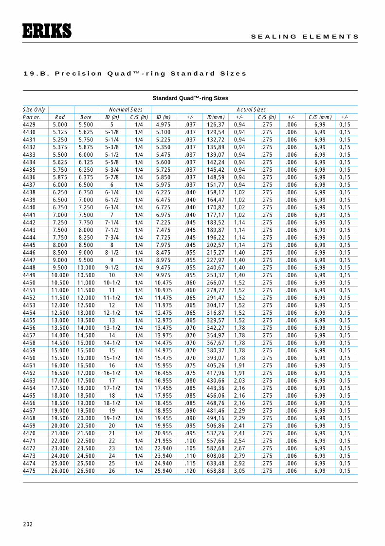
202
S E A L I N G E L E M E N T S
1 9 . B . P r e c i s i o n Q u a d ™ - r i n g S t a n d a r d S i z e s
Standard Quad™-ring Sizes
Size Only Nominal Sizes Actual SizesPart nr. Rod Bore ID (in) C/S (in) ID (in) +/- ID(mm) +/- C/S (in) +/- C/S (mm) +/-4429 5.000 5.500 5 1/4 4.975 .037 126,37 0,94 .275 .006 6,99 0,154430 5.125 5.625 5-1/8 1/4 5.100 .037 129,54 0,94 .275 .006 6,99 0,154431 5.250 5.750 5-1/4 1/4 5.225 .037 132,72 0,94 .275 .006 6,99 0,154432 5.375 5.875 5-3/8 1/4 5.350 .037 135,89 0,94 .275 .006 6,99 0,154433 5.500 6.000 5-1/2 1/4 5.475 .037 139,07 0,94 .275 .006 6,99 0,154434 5.625 6.125 5-5/8 1/4 5.600 .037 142,24 0,94 .275 .006 6,99 0,154435 5.750 6.250 5-3/4 1/4 5.725 .037 145,42 0,94 .275 .006 6,99 0,154436 5.875 6.375 5-7/8 1/4 5.850 .037 148,59 0,94 .275 .006 6,99 0,154437 6.000 6.500 6 1/4 5.975 .037 151,77 0,94 .275 .006 6,99 0,154438 6.250 6.750 6-1/4 1/4 6.225 .040 158,12 1,02 .275 .006 6,99 0,154439 6.500 7.000 6-1/2 1/4 6.475 .040 164,47 1,02 .275 .006 6,99 0,154440 6.750 7.250 6-3/4 1/4 6.725 .040 170,82 1,02 .275 .006 6,99 0,154441 7.000 7.500 7 1/4 6.975 .040 177,17 1,02 .275 .006 6,99 0,154442 7.250 7.750 7-1/4 1/4 7.225 .045 183,52 1,14 .275 .006 6,99 0,154443 7.500 8.000 7-1/2 1/4 7.475 .045 189,87 1,14 .275 .006 6,99 0,154444 7.750 8.250 7-3/4 1/4 7.725 .045 196,22 1,14 .275 .006 6,99 0,154445 8.000 8.500 8 1/4 7.975 .045 202,57 1,14 .275 .006 6,99 0,154446 8.500 9.000 8-1/2 1/4 8.475 .055 215,27 1,40 .275 .006 6,99 0,154447 9.000 9.500 9 1/4 8.975 .055 227,97 1,40 .275 .006 6,99 0,154448 9.500 10.000 9-1/2 1/4 9.475 .055 240,67 1,40 .275 .006 6,99 0,154449 10.000 10.500 10 1/4 9.975 .055 253,37 1,40 .275 .006 6,99 0,154450 10.500 11.000 10-1/2 1/4 10.475 .060 266,07 1,52 .275 .006 6,99 0,154451 11.000 11.500 11 1/4 10.975 .060 278,77 1,52 .275 .006 6,99 0,154452 11.500 12.000 11-1/2 1/4 11.475 .065 291,47 1,52 .275 .006 6,99 0,154453 12.000 12.500 12 1/4 11.975 .065 304,17 1,52 .275 .006 6,99 0,154454 12.500 13.000 12-1/2 1/4 12.475 .065 316.87 1,52 .275 .006 6,99 0,154455 13.000 13.500 13 1/4 12.975 .065 329,57 1,52 .275 .006 6,99 0,154456 13.500 14.000 13-1/2 1/4 13.475 .070 342,27 1,78 .275 .006 6,99 0,154457 14.000 14.500 14 1/4 13.975 .070 354,97 1,78 .275 .006 6,99 0,154458 14.500 15.000 14-1/2 1/4 14.475 .070 367,67 1,78 .275 .006 6,99 0,154459 15.000 15.500 15 1/4 14.975 .070 380,37 1,78 .275 .006 6,99 0,154460 15.500 16.000 15-1/2 1/4 15.475 .070 393,07 1,78 .275 .006 6,99 0,154461 16.000 16.500 16 1/4 15.955 .075 405,26 1,91 .275 .006 6,99 0,154462 16.500 17.000 16-1/2 1/4 16.455 .075 417,96 1,91 .275 .006 6,99 0,154463 17.000 17.500 17 1/4 16.955 .080 430,66 2,03 .275 .006 6,99 0,154464 17.500 18.000 17-1/2 1/4 17.455 .085 443,36 2,16 .275 .006 6,99 0,154465 18.000 18.500 18 1/4 17.955 .085 456,06 2,16 .275 .006 6,99 0,154466 18.500 19.000 18-1/2 1/4 18.455 .085 468,76 2,16 .275 .006 6,99 0,154467 19.000 19.500 19 1/4 18.955 .090 481,46 2,29 .275 .006 6,99 0,154468 19.500 20.000 19-1/2 1/4 19.455 .090 494,16 2,29 .275 .006 6,99 0,154469 20.000 20.500 20 1/4 19.955 .095 506,86 2,41 .275 .006 6,99 0,154470 21.000 21.500 21 1/4 20.955 .095 532,26 2,41 .275 .006 6,99 0,154471 22.000 22.500 22 1/4 21.955 .100 557,66 2,54 .275 .006 6,99 0,154472 23.000 23.500 23 1/4 22.940 .105 582,68 2,67 .275 .006 6,99 0,154473 24.000 24.500 24 1/4 23.940 .110 608,08 2,79 .275 .006 6,99 0,154474 25.000 25.500 25 1/4 24.940 .115 633,48 2,92 .275 .006 6,99 0,154475 26.000 26.500 26 1/4 25.940 .120 658,88 3,05 .275 .006 6,99 0,15
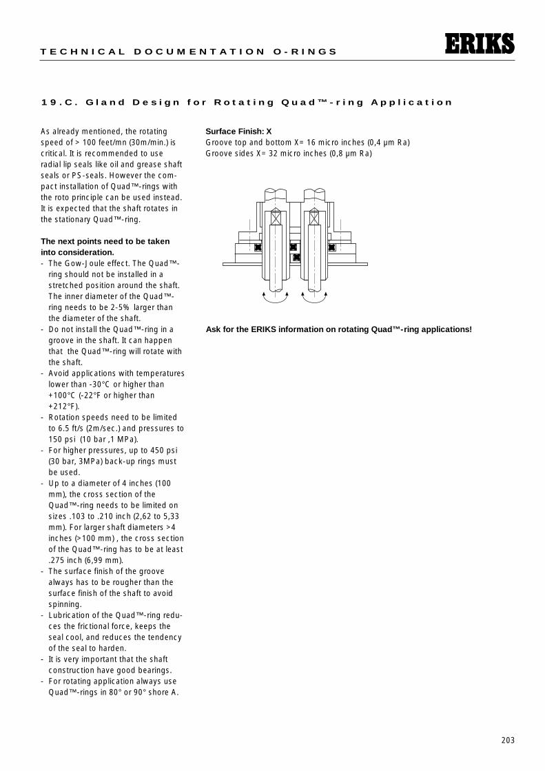
203
T E C H N I C A L D O C U M E N T A T I O N O - R I N G S
1 9 . C . G l a n d D e s i g n f o r R o t a t i n g Q u a d ™ - r i n g A p p l i c a t i o n
As already mentioned, the rotatingspeed of > 100 feet/mn (30m/min.) iscritical. It is recommended to useradial lip seals like oil and grease shaftseals or PS-seals. However the com-pact installation of Quad™-rings withthe roto principle can be used instead.It is expected that the shaft rotates inthe stationary Quad™-ring.
The next points need to be takeninto consideration.- The Gow-Joule effect. The Quad™-
ring should not be installed in astretched position around the shaft.The inner diameter of the Quad™-ring needs to be 2-5% larger thanthe diameter of the shaft.
- Do not install the Quad™-ring in agroove in the shaft. It can happenthat the Quad™-ring will rotate withthe shaft.
- Avoid applications with temperatureslower than -30°C or higher than+100°C (-22°F or higher than+212°F).
- Rotation speeds need to be limitedto 6.5 ft/s (2m/sec.) and pressures to150 psi (10 bar ,1 MPa).
- For higher pressures, up to 450 psi(30 bar, 3MPa) back-up rings mustbe used.
- Up to a diameter of 4 inches (100mm), the cross section of theQuad™-ring needs to be limited onsizes .103 to .210 inch (2,62 to 5,33mm). For larger shaft diameters >4inches (>100 mm) , the cross sectionof the Quad™-ring has to be at least.275 inch (6,99 mm).
- The surface finish of the groovealways has to be rougher than thesurface finish of the shaft to avoidspinning.
- Lubrication of the Quad™-ring redu-ces the frictional force, keeps theseal cool, and reduces the tendencyof the seal to harden.
- It is very important that the shaftconstruction have good bearings.
- For rotating application always useQuad™-rings in 80° or 90° shore A.
Surface Finish: XGroove top and bottom X= 16 micro inches (0,4 µm Ra)Groove sides X= 32 micro inches (0,8 µm Ra)
Ask for the ERIKS information on rotating Quad™-ring applications!
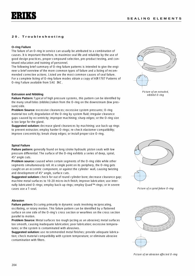
204
S E A L I N G E L E M E N T S
2 0 . T r o u b l e s h o o t i n g
Picture of an extruded, nibbled O-ring
Picture of a spiral failure O-ring
O-ring FailureThe failure of an O-ring in service can usually be attributed to a combination ofcauses. It is important therefore, to maximize seal life and reliability by the use ofgood design practices, proper compound selection, pre-product testing, and con-tinued education and training of personnel.The following brief summary of O-ring failure patterns is intended to give the engi-neer a brief overview of the more common types of failure and a listing of recom-mended corrective actions. Listed are the most common causes of seal failure. For a complete listing of O-ring failure modes obtain a copy of AIR1707 Patterns ofO-ring Failure available from SAE INC.
Extrusion and NibblingFailure Pattern: Typical of high pressure systems, this pattern can be identified bythe many small bites (nibbles) taken from the O-ring on the downstream (low pres-sure) side.Problem Source: excessive clearances; excessive system pressures; O-ring material too soft; degradation of the O-ring by system fluid; irregular clearancegaps caused by eccentricity; improper machining; sharp edges; or the O-ring sizeis too large for the gland. Suggested solution: decrease gland clearances by machining; use back-up ringsto prevent extrusion; employ harder O-rings; re-check elastomer compatibility;improve concentricity; break sharp edges; or install proper size O-ring.
Spiral FailureFailure pattern: generally found on long stroke hydraulic piston seals with lowpressure differential. The surface of the O-ring exhibits a series of deep, spiral, 45° angle cuts.Problem source: caused when certain segments of the O-ring slide while othersegments simultaneously roll. At a single point on its periphery, the O-ring getscaught on an eccentric component, or against the cylinder wall, causing twistingand development of 45° angle, surface cuts.Suggested solution: check for out of round cylinder bore; decrease clearance gap;machine metal surfaces to 10-20 micro-inch finish; improve lubrication; use inter-nally-lubricated O-rings; employ back-up rings; employ Quad™-rings; or in severecases use a T-seal.
AbrasionFailure pattern: Occuring primarily in dynamic seals involving reciprocating, oscillating, or rotary motion. This failure pattern can be identified by a flattened surface on one side of the O-ring’s cross section or wearlines on the cross sectionparallel to motion.Problem Source: Metal surfaces too rough (acting as an abrasive); metal surfacestoo smooth, causing inadequate lubrication; poor lubrication; excessive tempera-tures; or the system is contaminated with abrasives.Suggested solution: use recommended metal finishes; provide adequate lubrica-tion; check material compatibility with system temperature; or eliminate abrasivecontamination with filters.
Picture of an abrasion affected O-ring
205
T E C H N I C A L D O C U M E N T A T I O N O - R I N G S
2 0 . T r o u b l e s h o o t i n g
Picture of an O-ring subject to compression set
Picture of O-ring failure due to plasticizer extraction
Picture of a cracked O-ring
Compression SetFailure Pattern: common to both static and dynamic seals, compression set failureproduces flat surfaces on both sides of the O-ring cross section in the area beingsqeezed.Problem Source: selection of an elastomer with poor compression set properties;system pressure is too high; excessive swelling of O-ring material in system fluid;too much squeeze to achieve seal; incomplete curing of O-ring material during vul-canisation; or excessive system temperature. Suggested Solutions: employ a low compression set elastomer; specify an O-ringmaterial that resists operating or frictionally generated heat; re-check O-ring compatibility with system chemicals; reduce O-ring squeeze if possible; or inspectincoming O-rings for correct physical dimensions.
Weather or Ozone CrackingFailure Pattern: occurring in both static and dynamic seals exposed to atmos-pheres containing ozone and other air pollutants. This failure mode is marked bythe appearance of many small surface cracks perpendicular to the direction ofstress.Problem Source: ozone attacks unsaturated or double bond points in some poly-mer chains, causing chain scission. Cracking of the outside surface of the O-ring isthe result.Suggested Solution: employ O-ring elastomers that are resistant to ozone attack.
Heat Hardening and OxidationFailure Pattern: seen in both static and dynamic seals, in pneumatic or air service.The surface of the O-ring appears pitted and/or cracked, often accompanied by theflatness of high compression set.Problem Source: excessive environmental temperature causing excessive elastomer hardening, evaporation of plasticizer, and cracking from oxidation.Suggested Solution: lower operating temperature or specify high temperature andoxidation resistant O-ring materials.
Plasticizer ExtractionFailure Pattern: occurring in both static and dynamic seals, primarily in fuel systemservice. This failure pattern is marked by small cracks in the O-ring stress area,accompanied by a loss of physical volume.Problem Source: extraction of O-ring material plasticizer component by systemchemicals or fluids in a dry-out situation.Suggested Solution: employ chemically compatible O-ring material with low-to-noextractable plasticizer content.
Picture of a hardened and oxidated O-ring
206
S E A L I N G E L E M E N T S
Picture of an exploded O-ring
Picture of a damaged back-up and O-ring
Picture of a damaged O-ring
2 0 . T r o u b l e s h o o t i n g
Installation DamageFailure Pattern: occurring in both static and dynamic seals. This failure mode is markedby short cuts, notches, or a skinned or peripherally peeled surface on the O-ring.Problem Source: sharp edges on mating metal components of the O-ring gland;sharp threads over which the O-ring must pass during assembly; insufficient lead-inchamfer; blind grooves in multi-port valves; oversize O-ring I.D. on piston; undersizeO-ring I.D. on rod; twisting or pinching of the O-ring during installation; or no O-ringlubrication during installation.Suggested Solution: break sharp edges on mating metal components; coverthreads with tubes or tape during O-ring installation; provide a 20° lead-in chamfer;break sharp corners of chamfer and O-ring groove edges; install correctly sized O-rings; and use lubrication during assembly.
Explosive DecompressionFailure Pattern: marked by random short splits or ruptures going deep into the O-ring cross section. When the O-ring is first removed, the surface may also be covered with small blisters.Problem Source: absorption of gas by the O-ring while operating in high pressureconditions. Subsequent rapid decrease in system pressure traps within the O-ringmicropores, causing surface blisters and ruptures as the gas seeks an avenue ofescape.Suggested Solution: increase time for decompression; increase material hardnessto 80°-95° shore A; reduce O-ring cross sectional size; or specify a decompressionresistant material, such as a harder nitrile or special Viton® 514162.
Back-up ring FailureFailure Pattern: occurring exclusively in dynamic seals, the O-ring surface isnotched or nibbled adjacent to the scarf cut or overlap of the back-up ring.Problem source: thermal changes, pressure surges, and extrusion of the back-upring into the gap.Suggested Solution: check design details and consider the solid type of back-upring. Use PEEK (plastic) or another material.
207
T E C H N I C A L D O C U M E N T A T I O N O - R I N G S
2 1 . G l o s s a r y
AbrasionProgressive wearing away of material by mechanical action. Abrasion ResistanceThe ability of a rubber compound to resist mechanical wear.AbsorptionThe physical mechanism by which one substance attracts and takes up another substance.Accelerated Life TestAny set of conditions designed to reproduce in a short time the deteriorating effect obtained under normal service conditions.Accelerated Service Test A service or bench test in which some service condition, such as speed, temperature, or continuity of operation, is exaggeratedin order to obtain a result in shorter time.AcceleratorA substance which hastens the vulcanization of an elastomer causing it to take place in a shorter time or at a lower temperature.Acid Resistant Withstands the action of acids.Adhere To cling or stick together.AdhesionSusceptibility of rubber to stick to a contact surface.AflasTrade name of Asahi Glass for TFE Propylene. After Cure Continuation of vulcanization after the desired cure is effected and the heat source removed.AgingTo undergo changes in physical properties with age or lapse of time. Aging, Air Oven A means of accelerating the change in physical properties of rubber compounds by exposing them to the action of air at an ele-vated temperature.Aging, Air Pressure Heat A means of accelerating the change in physical properties of rubber compounds by exposing them to the action of air underpressure at an elevated temperature.Aging, Oxygen Bomb A means of accelerating the change in physical properties of rubber compounds by exposing them to the action of oxygen at anelevated temperature and pressure.Air BombSimilar to an oxygen bomb but used with air. Used for accelerated aging test.Air Checks Surface marking or depressions due to trapping air between the materials being cured and the mold or press surface.Air CuringThe vulcanization of a rubber product in air as distinguished from vulcanizing in a press or steam vulcanizer.Ambient Temperature The environment temperature surrounding the object under consideration.Aniline Point of OilThe lowest temperature at which equal volumes of pure aniline and a particular oil will completely dissolve in one another. Theaniline point generally affects the swell.AntioxidantAn organic substance which inhibits or retards oxidation.Atmospheric Cracking Cracks produced in surface of rubber articles by exposure to atmospheric conditions.Automotive fuelsFuels used for automobile engines.Average Modulus Total change of stress divided by total change of strain, i.e., the average slope of the stress-strain curve. Employed when modu-lus varies from point to point.
208
S E A L I N G E L E M E N T S
2 1 . G l o s s a r y
Back Rind A burn-back into the part at a mold line separation caused by too soft a rubber stock, excessive acceleration, or too low a plas-ticity.Back-up ring Washer-like device installed next to O-ring to prevent extrusion.Bench Test A modified service test in which the service conditions are approximated, but the equipment is conventional laboratory equip-ment and not necessarily identical with that in which the product will be employed.Bending Modulus Force required to induce bending around a given radius, and hence a measure of stiffness.Bleeding Migration to the surface of plasticizers, waxes, or similar materials to form a film or beads.BlemishA mark, deformity, or injury which impairs the appearance.Blisters A raised spot on the surface or a separation between layers usually forming a void or air-filled space in the vulcanized article.Bloom A discoloration or change in appearance of the surface of a rubber product caused by the migration of a liquid or solid to thesurface. Examples: sulfur broom, wax broom. Not to be confused with dust on the surface from external sources.BreakA separation or discontinuity in any part of an article.Breakout Force to inaugural sliding. Expressed in same terms as friction. An excessive breakout value is taken as an indication of thedevelopment of adhesion.BrittlenessTendency to crack when subjected to deformation. Buna NA general term for the copolymers of butadiene and acrylonitrile. Typical commercial polymers are Hycar and Paracril. Buna SA general term for the copolymers of butadiene and styrene.Butt JointJoining two ends of material whereby the junction is perpendicular to the plane of an O-ring.ButylA synthetic rubber of the polybutene type exhibiting very low permeability to gases.
Coefficient of Thermal Expansion Average expansion per degree over a stated temperature range, expressed in a fraction of initial dimension. May be linear or vol-umetric. Cold Flexibility Flexibility following exposure to a predetermined low temperature for a predetermined time.Cold Flow Continued deformation under stress.Cold Resistant Withstands the effect of cold or low temperatures without loss of serviceability.Commercially Smooth Degree of smoothness of the surface of an article which is acceptable for use.Compound A term applied to either vulcanized or unvulcanized mixtures of elastomers and other ingredients necessary to make a usefulrubber-like material.Compression Modulus The ratio of the compressive stress to the resulting compressive strain (the latter expressed as a fraction of the original height orthickness in the direction of the force). Compression Modulus may be either static or dynamic.Compression Set The decrease in thickness of a rubber specimen which has been deformed under specific conditions of load, time, and tempera-ture. It is usual expressed as a percentage of the initial compression of the test sample.
209
T E C H N I C A L D O C U M E N T A T I O N O - R I N G S
Conductive rubberA rubber having qualities of conduction or transmitting heat or electricity. Most generally applied to rubber products used toconduct static electricity. Conductivity Quality or power of conducting or transmitting heat or electricity.Copolymer A polymer consisting of two different monomers chemically combined.Corrosion (Packing) Corrosion of rigid member (usually metal) where it contacts packing. The actual corroding agent is fluid medium trapped in theinterface.Corrosive (Packing) A property of packing whereby it is assumed, often incorrectly, to promote corrosion of the rigid member by the trapped fluid.CrackingA sharp break or fissure in the surface. Generally due to excessive strain.CreepThe relaxation of a rubber material while under stress.Cross sectionAn O-ring viewed as it were if cut at right angles to the axis showing internal structure. Curing Date O-ring molding date. Curing TemperatureThe temperature at which the rubber product is vulcanized.CylinderChamber in which piston, plunger, ram, rod, or shaft is driven by or against the pressure medium.
DegassingThe intentional but controlled outgassing of a rubber substance.Durometer An instrument for measuring the hardness of rubber. Measures the resistance to the penetration of an indentor point into thesurface of rubber. DynamicO-ring application in which the O-ring is subject to movement or moving parts. Dynamic Packing A packing employed in a joint whose members are in relative motion.Dynamic Seal A seal required to prevent leakage past parts which are in relative motion.
ElasticityThe property of an article which tends to return to its original shape after deformation.Elastic Limit The greatest stress which a material is capable of developing without a permanent deformation remaining upon completerelease of the stress. In rubber, the elastic limit as above defined is very low and sometimes practically non-existent. Usually thisterm is replaced by various load limits for specific cases in which the resulting permanent deformations are not zero but are neg-ligible.ElastomerA general term for an elastic, rubber-like substance. A polymeric material which may be compressed or otherwise deformed,and by virtue of its molecular structure, will recover almost completely to its original form.EMI Electromagnetic InterferenceAn electromagnetic emission, which has a disturbing effect on devices exposed to it.EMI GasketA component, usually incorporating a formed resilient elastomer, which will allow a seam or enclosure panel interface to be reli-ably interconnected (electrical bonded) along the entire joint.Elongation Increase in length expressed numerically as a fraction or percentage of initial length.
2 1 . G l o s s a r y
210
S E A L I N G E L E M E N T S
Ethylene PropyleneElastomer prepared from ethylene and propylene monomers.Explosive DecompressionExpanding of gas (or volatile liquid) in case of a sudden pressure drop. ExtrusionDistortion, under pressure, of portion of seal into clearance between mating metal parts.
FamTest fluid for extraction of softeners out of the rubber compound. FillerChemically inert, finely divided material added to the polymer to aid in processing and improving properties of abrasion resistance and strength - gives it varying degrees of hardness.FlashExcess rubber left around rubber part after molding due to space between mating mold surfaces; removed by trimming. Flex CrackingA surface cracking induced by repeated bending or flexing.Flex LifeThe relative ability of a rubber article to withstand dynamic bending stresses.Flock Fibers added to rubber compounds.Flow Cracks Surface imperfections due to improper flow and failure of stock to knit or blend with itself during the molding operation.Fluorocarbon, PerfluorocarbonHighly fluorinated carbon backboned polymers.Food serviceCompound ingredients for contact with food products. FrictionResistance to motion due to the contact of surfaces. Friction, Breakout Initial or starting friction developed of a dynamic seal.Friction, Running Friction developed during operation of a dynamic seal.Fuel, AromaticFuel which contains benzene or aromatic hydrocarbons.Fuel, Non-AromaticFuel which is composed of straight chain hydrocarbons.
Gland Seal assembly, including the O-ring; groove which holds the O-ring and the contacting surfaces.Gow-Joule effectElastomers under stretch give higher tension when the temperatures rises.
HardnessProperty or extent of being hard. Measured in degrees and based on the penetration into the rubber of a defined indentor undera set load.Hardness Shore A Durometer reading in degrees of the hardness of the rubber based on a shore durometer. HomogeneousGeneral - a material of uniform composition throughout.Hycar Commercial name of B.F. Goodrich for polyacrylate rubber, ACM polymer of acrylic acid ester. Hypalon Commercial name for a chlorosulphonated derivative of polyethylene.
2 1 . G l o s s a r y
211
T E C H N I C A L D O C U M E N T A T I O N O - R I N G S
2 1 . G l o s s a r y
Immediate Set The deformation found by measurement immediately after removal of the load causing the deformation.ImmersionPlacing an article into a fluid, generally so it is completely covered.Impact The single instantaneous stroke or contact of a moving body with another either moving or at rest, such as a large lump of material dropping on a conveyor belt.Internal LubricationThe incorporation of friction reducing ingredients (graphite, molybdenum disulfide, powdered Teflon®, or organic lubricants) inthe rubber compound.
LabsfreeThe absence of any trace of ingredient on the surface of the O-ring which can cause adhesion problems (i.a. paint industry).Leakage RateThe rate at which either a gas or liquid passes a barrier.Life Test A laboratory procedure used to determine the amount and duration of resistance of a rubber article to a specific set of destruc-tive forces or conditions. Linear Expansion Expansion in any one linear dimension or the average of all linear dimensions.LogySluggish, low snap or recovery of a material.Low Temperature Flexibility The ability of a rubber product to be flexed, bent or bowed at low temperatures.Low Temperature Flexing Act or instance of repeated bending or bowing a rubber product under conditions of low temperature.
MediaA liquid, a gas, or a mixture of both. MemoryTendency of a material to return to original shape after deformation.Micro O-ringsAny O-ring that measures less than .4 inch (1 mm) in either inside diameter or cross section.Mirror Finish A bright, polished surface.Misalignment Departure from alignment.Mismatch Poor matching or meeting in splice.Modulus Tensile stress at a specified elongation (generally 100%). Modulus of Elasticity One of the several measurements of stiffness or resistance to deformation, but often incorrectly used to indicate specifically stat-ic tension modulus. Mold CavityHollow space or cavity in the mold which is used to impart the desired form to the product being molded.Mold FinishThe uninterrupted surface produced by intimate contact of rubber with the surface of the mold at vulcanization.Mold LubricantA material usually sprayed onto the mold cavity surface, to facilitate the easy removal of the molded rubber parts.Mold Marks Indentations or ridges embossed into the skin of the molded product by irregularities in the mold cavity surface.Mold RegisterMeans used to align the parts of a mold.
212
S E A L I N G E L E M E N T S
2 1 . G l o s s a r y
Mooney ScorchThe measurement of the rate at which a rubber compound will precure or set up by means of the Mooney Viscometer.Mooney Viscosity The measurement of the plasticity or viscosity of a not compounded or compounded but not vulcanized rubber and rubber-likematerial by means of the Mooney Shearing Disk Viscometer.
Natural RubberRaw or crude rubber obtained from vegetable sources, basically the unsaturated polymer of isoprene.NeopreneHomopolymers of chloroprene. DuPont's name for chloroprene rubber.Nick A small notch, slit, or cut.Nitrile (Buna N) Copolymer of butadiene and acrylonitrile; known commercially as Butaprene, Chemigum, Hycar OR, Perbunan and Paracril.(See Buna N) Nominal LengthThe desired length from which tolerances are set.Non-Blooming The absence of bloom.
Off-RegisterMisalignment of mold halves causing an out-of-round O-ring cross section.Oil ResistantAbility of a vulcanized rubber to resist the swelling and deteriorating effects of various type oils.Oil SwellThe change in volume of a rubber article due to absorption of oil.O-ring An elastomeric seal of homogeneous composition molded in one piece to the configuration of a torus with circular cross section(doughnut). The O-ring is used as a dynamic or static seal usually installed in a machined groove.Optimum Cure State of vulcanization at which maximum desired property is attained.Over CureA degree of cure greater than the optimum.OutgassingA vacuum phenomenon where a substance spontaneously releases volatile constituents in the form of vapors or gases.Oxidation The reaction of oxygen on a rubber product, usually detected by a change in the appearance or feel of the surface or by achange in physical properties.Oxygen Bomb A chamber capable of holding oxygen at an elevated pressure which can be heated to an elevated temperature. Used for anaccelerated aging test (See Aging).Ozone Resistant Withstands the deteriorating effects of ozone (generally cracking).
PackingA flexible device used to retain fluids under pressure or seal out foreign matter.Packing GrooveA groove carved in a flange, or in one member of a concentric joint, to accommodate a packing.PerbunanStandard Oil of New Jersey's name for chloroprene rubber.Permanent Set Permanent set is the deformation remaining after a specimen has been stressed in tension a prescribed amount of time andreleased for a definite period.
213
T E C H N I C A L D O C U M E N T A T I O N O - R I N G S
2 1 . G l o s s a r y
Permeability Property of rubber or other materials which permits passage of gas through the molecular structure of the material. Pit or Pock Mark A circular depression, usually small. PlasticizerA substance, usually a liquid, added to an elastomer to decrease stiffness, improve low temperature properties, and improveprocessing.PolymerA material formed by the joining together of many (poly) individual units (mer) of a monomer.PorosityQuality of state of being porous due to presence of globular structural voids.Post CureThe second step in the vulcanization process for some elastomers. Provides stabilization of parts and drives off decompositionproducts resulting from the vulcanization process.
RadiationEmission of alpha particles, beta particles, or electromagnetic energy (gamma radiation). Register, Off or Uneven Nonconformity of finished article with design dimensions due to mold misalignment during cure.Relative Humidity The ratio of the quantity of water vapor actually present in the atmosphere to the greatest amount possible at the given tempera-ture.ResilienceCapable of returning to original size and shape after deformation.RMS and RaRoot Mean Square - The measure of surface roughness, obtained as the square root of the sum of the squares of micro-inchdeviation from true flat. 1 RMS micro-inch = 0,025 µRA micro-meter.Rough Trim Removal of superfluous parts by pulling or picking. Usually a small portion of the flash or sprue remains attached to the product. Rubber, ChloropreneHomopolymer of chloroprene. Runout (Shaft) Same as Gyration. When expressed in inches or mm alone or accompanied by abbreviation "TIR" (total indicator reading), itrefers to twice the radial distance between shaft axis and axis of rotation.
SealAny device used to prevent the passage of a gas or liquid.Service Operating conditions to be met.ShaftRotating member within cylinder; not in contact with the walls.Shelf-agingThe change in a material’s properties which occurs in storage with time.Shield, EMIElectrically conductive materials placed around a circuit, component or cable, to suppress the effect of electromagnetic field.Shore A HardnessSee Hardness and Durometer.ShrinkageDecreased volume of unit caused by air drying after immersion in fluid.Silicone fluidsOils and greases based on silicones. Silicone, FluorosiliconeSemi-organic elastomer, containing silicone. Silicone freeO-rings which are produced with a silicone free mold lubricant.
214
S E A L I N G E L E M E N T S
2 1 . G l o s s a r y
Size, ActualActual dimensions of the O-ring, including tolerance limits.Size, NominalApproximate size of O-ring in fractional dimensions.Size numberNumber assigned to indicate inside and cross section diameters of an O-ring. Sizes established in SAE standard AS 568 havebeen adopted by the military and industry.Specific GravityThe ratio of the weight of a given substance to the weight of an equal volume of water at a specified temperature.SpecimensProduct parts used for testing. Sprue MarksMarks left on the surface of a rubber part, usually elevated, after removal of the flash. Squeeze cross section diametrical compression of O-ring between bottom surface of the groove and surface of other mating metal part inthe gland assembly. Static Stationary application such as a gasket.Static Seal Seal designed to work between parts having no relative motions.Stress Force per unit of original cross sectional area required to stretch a specimen to a stated elongation.Stress RelaxationThis is the phenomenon exhibited by an elastomer under constant compression, whereby the opposing force exerted by theelastomer decreases with time.Sun Checking Surface cracks, checks or crazing caused by exposure to direct or indirect sunlight.SwellIncreased volume of unit caused by immersion in a fluid.Synthetic RubberManufactured elastomers.
Tear ResistanceStrength of a compound as resistance to growth of a cut or nick when tension is applied to the cut specimen. Temperature Range Lowest temperature at which rubber remains flexible and highest temperature at which it will function.Tensile Strength Force in pounds per square inch or in kilograms per square centimeter required to cause the rupture of a specimen of a rubbermaterial.TerpolymerA polymer consisting of at least three different monomers chemically combined.Thermal EffectsDeterioration at higher temperatures. Thermal Expansion Expansion caused by increase in temperature. May be linear and volumetric.ThiokolA synthetic rubber of the polysulfide type.Torque The turning power of a shaft.TorrComes from the tube of Torricelli. The unit of pressure used in vacuum measurement. It is equal to 1/760 of a standard atmos-phere, and for all practical purposes is equivalent to one millimeter of mercury (mm HG).TrimThe process involving removal of mold flash.
215
T E C H N I C A L D O C U M E N T A T I O N O - R I N G S
2 1 . G l o s s a r y
Trim CutDamage to mold skin or finish by too close trimming.TR-10The warming up temperature at which a frozen O-ring regains 10% of its elasticity.
Under-Cure Degree of cure less than optimum. May be evidenced by inferior physical properties.
VacuumSituation in a given space that is occupied by a gas at less than atmospheric pressure. Vacuum LevelThe term used to denote the degree of Rough, Medium, High, Hard, or Ultra Hard vacuum evidenced by its pressure in torr (mm HG). VamacDuPont-Dow Elastomers' name for Ethylene Acrylate.Vapor PressureThe maximum pressure exerted by a liquid (or solid) heated to a given temperature in a closed container.Viscosity A manifestation of internal friction opposed to mobility. The property of fluids and plastic solids by which they resist an instanta-neous change of shape, i.e., resistance to flow.VoidsThe absence of material or an area devoid of materials where not intended. Volume Change Change in volume of a specimen which has been immersed in a designated fluid under specified condition of time and tempera-ture. Expressed as a percentage of the original volume.Volume Swell Increase in physical size caused by the swelling action of a liquid.Vulcanization A thermo-setting involving the use of heat and pressure and which results in greatly increased strength and elasticity of rubber-like materials.Vulcanizing AgentA material which produces vulcanization of an elastomer.Vulc-O-ringAn O-ring manufactured from O-ring cord by splicing and bonding or vulcanizing.
WidthRadial dimension. For packing rings or sets the term "packing space" is preferred.Wiper ringA ring employed to remove excess fluid, mud, etc., from a reciprocating member before it reaches the seal.
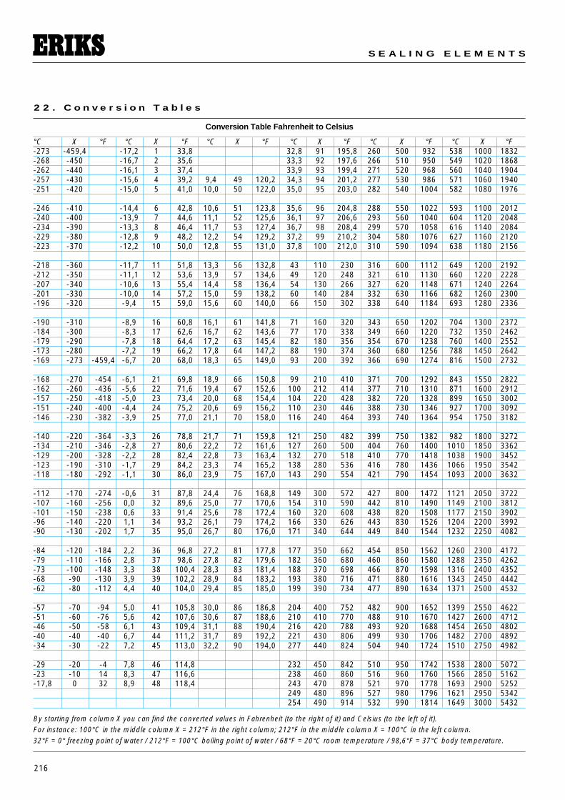
216
S E A L I N G E L E M E N T S
2 2 . C o n v e r s i o n T a b l e s
Conversion Table Fahrenheit to Celsius
°C X °F °C X °F °C X °F °C X °F °C X °F °C X °F-273 -459,4 -17,2 1 33,8 32,8 91 195,8 260 500 932 538 1000 1832-268 -450 -16,7 2 35,6 33,3 92 197,6 266 510 950 549 1020 1868-262 -440 -16,1 3 37,4 33,9 93 199,4 271 520 968 560 1040 1904-257 -430 -15,6 4 39,2 9,4 49 120,2 34,3 94 201,2 277 530 986 571 1060 1940-251 -420 -15,0 5 41,0 10,0 50 122,0 35,0 95 203,0 282 540 1004 582 1080 1976
-246 -410 -14,4 6 42,8 10,6 51 123,8 35,6 96 204,8 288 550 1022 593 1100 2012-240 -400 -13,9 7 44,6 11,1 52 125,6 36,1 97 206,6 293 560 1040 604 1120 2048-234 -390 -13,3 8 46,4 11,7 53 127,4 36,7 98 208,4 299 570 1058 616 1140 2084-229 -380 -12,8 9 48,2 12,2 54 129,2 37,2 99 210,2 304 580 1076 627 1160 2120-223 -370 -12,2 10 50,0 12,8 55 131,0 37,8 100 212,0 310 590 1094 638 1180 2156
-218 -360 -11,7 11 51,8 13,3 56 132,8 43 110 230 316 600 1112 649 1200 2192-212 -350 -11,1 12 53,6 13,9 57 134,6 49 120 248 321 610 1130 660 1220 2228-207 -340 -10,6 13 55,4 14,4 58 136,4 54 130 266 327 620 1148 671 1240 2264-201 -330 -10,0 14 57,2 15,0 59 138,2 60 140 284 332 630 1166 682 1260 2300-196 -320 -9,4 15 59,0 15,6 60 140,0 66 150 302 338 640 1184 693 1280 2336
-190 -310 -8,9 16 60,8 16,1 61 141,8 71 160 320 343 650 1202 704 1300 2372-184 -300 -8,3 17 62,6 16,7 62 143,6 77 170 338 349 660 1220 732 1350 2462-179 -290 -7,8 18 64,4 17,2 63 145,4 82 180 356 354 670 1238 760 1400 2552-173 -280 -7,2 19 66,2 17,8 64 147,2 88 190 374 360 680 1256 788 1450 2642-169 -273 -459,4 -6,7 20 68,0 18,3 65 149,0 93 200 392 366 690 1274 816 1500 2732
-168 -270 -454 -6,1 21 69,8 18,9 66 150,8 99 210 410 371 700 1292 843 1550 2822-162 -260 -436 -5,6 22 71,6 19,4 67 152,6 100 212 414 377 710 1310 871 1600 2912-157 -250 -418 -5,0 23 73,4 20,0 68 154,4 104 220 428 382 720 1328 899 1650 3002-151 -240 -400 -4,4 24 75,2 20,6 69 156,2 110 230 446 388 730 1346 927 1700 3092-146 -230 -382 -3,9 25 77,0 21,1 70 158,0 116 240 464 393 740 1364 954 1750 3182
-140 -220 -364 -3,3 26 78,8 21,7 71 159,8 121 250 482 399 750 1382 982 1800 3272-134 -210 -346 -2,8 27 80,6 22,2 72 161,6 127 260 500 404 760 1400 1010 1850 3362-129 -200 -328 -2,2 28 82,4 22,8 73 163,4 132 270 518 410 770 1418 1038 1900 3452-123 -190 -310 -1,7 29 84,2 23,3 74 165,2 138 280 536 416 780 1436 1066 1950 3542-118 -180 -292 -1,1 30 86,0 23,9 75 167,0 143 290 554 421 790 1454 1093 2000 3632
-112 -170 -274 -0,6 31 87,8 24,4 76 168,8 149 300 572 427 800 1472 1121 2050 3722-107 -160 -256 0,0 32 89,6 25,0 77 170,6 154 310 590 442 810 1490 1149 2100 3812-101 -150 -238 0,6 33 91,4 25,6 78 172,4 160 320 608 438 820 1508 1177 2150 3902-96 -140 -220 1,1 34 93,2 26,1 79 174,2 166 330 626 443 830 1526 1204 2200 3992-90 -130 -202 1,7 35 95,0 26,7 80 176,0 171 340 644 449 840 1544 1232 2250 4082
-84 -120 -184 2,2 36 96,8 27,2 81 177,8 177 350 662 454 850 1562 1260 2300 4172-79 -110 -166 2,8 37 98,6 27,8 82 179,6 182 360 680 460 860 1580 1288 2350 4262-73 -100 -148 3,3 38 100,4 28,3 83 181,4 188 370 698 466 870 1598 1316 2400 4352-68 -90 -130 3,9 39 102,2 28,9 84 183,2 193 380 716 471 880 1616 1343 2450 4442-62 -80 -112 4,4 40 104,0 29,4 85 185,0 199 390 734 477 890 1634 1371 2500 4532
-57 -70 -94 5,0 41 105,8 30,0 86 186,8 204 400 752 482 900 1652 1399 2550 4622-51 -60 -76 5,6 42 107,6 30,6 87 188,6 210 410 770 488 910 1670 1427 2600 4712-46 -50 -58 6,1 43 109,4 31,1 88 190,4 216 420 788 493 920 1688 1454 2650 4802-40 -40 -40 6,7 44 111,2 31,7 89 192,2 221 430 806 499 930 1706 1482 2700 4892-34 -30 -22 7,2 45 113,0 32,2 90 194,0 277 440 824 504 940 1724 1510 2750 4982
-29 -20 -4 7,8 46 114,8 232 450 842 510 950 1742 1538 2800 5072-23 -10 14 8,3 47 116,6 238 460 860 516 960 1760 1566 2850 5162-17,8 0 32 8,9 48 118,4 243 470 878 521 970 1778 1693 2900 5252
249 480 896 527 980 1796 1621 2950 5342254 490 914 532 990 1814 1649 3000 5432
By starting from column X you can find the converted values in Fahrenheit (to the right of it) and Celsius (to the left of it).For instance: 100°C in the middle column X = 212°F in the right column; 212°F in the middle column X = 100°C in the left column.32°F = 0° freezing point of water / 212°F = 100°C boiling point of water / 68°F = 20°C room temperature / 98,6°F = 37°C body temperature.
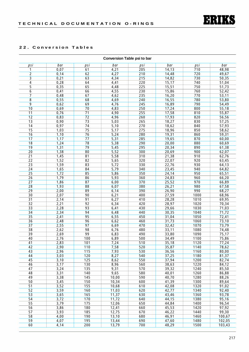
217
T E C H N I C A L D O C U M E N T A T I O N O - R I N G S
2 2 . C o n v e r s i o n T a b l e s
Conversion Table psi to bar
psi bar psi bar psi bar psi bar1 0,07 61 4,21 205 14,13 710 48,982 0,14 62 4,27 210 14,48 720 49,673 0,21 63 4,34 215 14,82 730 50,354 0,28 64 4,41 220 15,17 740 51,045 0,35 65 4,48 225 15,51 750 51,736 0,41 66 4,55 230 15,86 760 52,427 0,48 67 4,62 235 16,20 770 53,118 0,55 68 4,69 240 16,55 780 53,809 0,62 69 4,76 245 16,89 790 54,4910 0,69 70 4,83 250 17,24 800 55,1811 0,76 71 4,90 255 17,58 810 55,8712 0,83 72 4,96 260 17,93 820 56,5613 0,90 73 5,03 265 18,27 830 57,2514 0,97 74 5,10 270 18,62 840 57,9315 1,03 75 5,17 275 18,96 850 58,6216 1,10 76 5,24 280 19,31 860 59,3117 1,17 77 5,31 285 19,65 870 60,0018 1,24 78 5,38 290 20,00 880 60,6919 1,31 79 5,45 295 20,34 890 61,3820 1,38 80 5,52 300 20,69 900 62,0721 1,45 81 5,58 310 21,38 910 62,7622 1,52 82 5,65 320 22,07 920 63,4523 1,59 83 5,72 330 22,76 930 64,1324 1,65 84 5,79 340 23,45 940 64,8225 1,72 85 5,86 350 24,14 950 65,5126 1,79 86 5,93 360 24,83 960 66,2027 1,86 87 6,00 370 25,52 970 66,8928 1,93 88 6,07 380 26,21 980 67,5829 2,00 89 6,14 390 26,90 990 68,2730 2,07 90 6,21 400 27,59 1000 68,9631 2,14 91 6,27 410 28,28 1010 69,9532 2,21 92 6,34 420 28,97 1020 70,3433 2,28 93 6,41 430 29,66 1030 71,0334 2,34 94 6,48 440 30,35 1040 71,7235 2,41 95 6,55 450 31,04 1050 72,4136 2,48 96 6,62 460 31,73 1060 73,1037 2,55 97 6,69 470 32,42 1070 73,7938 2,62 98 6,76 480 33,11 1080 74,4839 2,69 99 6,83 490 33,80 1090 75,1740 2,76 100 6,89 500 34,49 1100 75,8641 2,83 101 7,24 510 35,18 1120 77,2442 2,90 110 7,58 520 35,87 1140 78,6243 2,96 115 7,93 530 36,56 1160 80,0044 3,03 120 8,27 540 37,25 1180 81,3745 3,10 125 8,62 550 37,94 1200 82,7446 3,17 130 8,96 560 38,63 1220 84,1247 3,24 135 9,31 570 39,32 1240 85,5048 3,31 140 9,65 580 40,01 1260 86,8849 3,38 145 10,00 590 40,70 1280 88,2650 3,45 150 10,34 600 41,39 1300 89,6451 3,52 155 10,68 610 42,08 1320 91,0252 3,59 160 11,03 620 42,77 1340 92,4053 3,65 165 11,37 630 43,46 1360 93,7854 3,72 170 11,72 640 44,15 1380 95,1655 3,79 175 12,06 650 44,84 1400 96,5456 3,86 180 12,41 660 45,53 1420 97,9257 3,93 185 12,75 670 46,22 1440 99,3058 4,00 190 13,10 680 46,91 1460 100,6759 4,07 195 13,44 690 47,60 1480 102,0560 4,14 200 13,79 700 48,29 1500 103,43
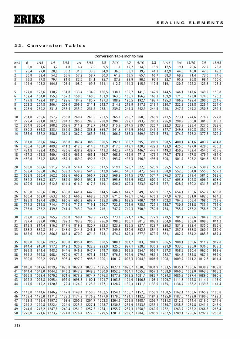
218
S E A L I N G E L E M E N T S
2 2 . C o n v e r s i o n T a b l e s
Conversion Table inch to mm
inch 0 1/16 1/8 3/16 1/4 5/16 3/8 7/16 1/2 9/16 5/8 11/16 3/4 13/16 7/8 15/160 0,0 1,6 3,2 4,8 6,4 7,9 9,5 11,1 12,7 14,3 15,9 17,5 19,1 20,6 22,2 23,81 25,4 27,0 28,6 30,2 31,8 33,3 34,9 36,5 38,1 39,7 41,3 42,9 44,5 46,0 47,6 49,22 50,8 52,4 54,0 55,6 57,2 58,7 60,3 61,9 63,5 65,1 66,7 68,3 69,9 71,4 73,0 74,63 76,2 77,8 79,4 81,0 82,6 84,1 85,7 87,3 88,9 90,5 92,1 93,7 95,3 96,8 98,4 100,04 101,6 103,2 104,8 106,4 108,0 109,5 111,1 112,7 114,3 115,9 117,5 119,1 120,7 122,2 123,8 125,4
5 127,0 128,6 130,2 131,8 133,4 134,9 136,5 138,1 139,7 141,3 142,9 144,5 146,1 147,6 149,2 150,86 152,4 154,0 155,6 157,2 158,8 160,3 161,9 163,5 165,1 166,7 168,3 169,9 171,5 173,0 174,6 176,27 177,8 179,4 181,0 182,6 184,2 185,7 187,3 188,9 190,5 192,1 193,7 195,3 196,9 198,4 200,0 201,68 203,2 204,8 206,4 208,0 209,6 211,1 212,7 214,3 215,9 217,5 219,1 220,7 222,3 223,8 225,4 227,09 228,6 230,2 231,8 233,4 235,0 236,5 238,1 239,7 241,3 242,9 244,5 246,1 247,7 249,2 250,8 252,4
10 254,0 255,6 257,2 258,8 260,4 261,9 263,5 265,1 266,7 268,3 269,9 271,5 273,1 274,6 276,2 277,811 279,4 281,0 282,6 284,2 285,8 287,3 288,9 290,5 292,1 293,7 295,3 296,9 298,9 300,0 301,6 303,212 304,8 306,4 308,0 309,6 311,2 312,7 314,3 315,9 317,5 319,1 320,7 322,3 323,9 325,4 327,0 328,613 330,2 331,8 333,4 335,0 366,0 338,1 339,7 341,3 342,9 344,5 346,1 347,7 349,3 350,8 352,4 354,014 355,6 357,2 358,8 360,4 362,0 363,5 365,1 366,7 368,3 369,9 371,5 373,1 374,7 376,2 377,8 379,4
15 381,0 382,6 384,2 385,8 387,4 388,9 390,5 392,1 393,7 395,3 396,9 398,5 400,1 401,6 403,2 404,816 406,4 408,0 409,6 411,2 412,8 414,3 415,9 417,5 419,1 420,7 422,3 423,9 425,5 427,0 428,6 430,217 431,8 433,4 435,0 436,6 438,2 439,7 441,3 442,9 444,5 446,1 447,7 449,3 450,9 452,4 454,0 455,618 457,2 458,8 460,4 462,0 463,6 465,1 466,7 468,3 469,9 471,5 473,1 474,7 476,3 477,8 479,4 481,019 482,6 184,2 485,8 487,4 489,0 490,5 492,1 493,7 495,3 496,9 498,5 500,1 501,7 503,2 504,8 506,4
20 508,0 509,6 511,2 512,8 514,4 515,9 517,5 519,1 520,7 522,3 523,9 525,5 527,1 528,6 530,2 531,821 533,4 535,0 536,6 538,2 539,8 541,3 542,9 544,5 546,1 547,7 549,3 550,9 552,5 554,0 555,6 557,222 558,8 560,4 562,0 563,6 665,2 566,7 568,3 569,9 571,5 573,1 574,7 576,3 577,9 579,4 581,0 582,623 584,2 585,8 587,4 589,0 590,6 592,1 593,7 595,3 596,9 598,5 600,1 601,7 603,3 604,8 606,4 608,024 609,6 611,2 612,8 614,4 616,0 617,5 619,1 620,7 622,3 623,9 625,5 627,1 628,7 630,2 631,8 633,4
25 635,0 636,6 638,2 639,8 641,4 642,9 644,5 646,1 647,7 649,3 650,9 652,5 654,1 655,6 657,2 658,826 660,4 662,0 663,6 665,2 666,8 668,3 669,9 671,5 673,1 674,7 676,3 677,9 679,5 681,0 682,6 684,227 685,8 687,4 689,0 690,6 692,2 693,7 695,3 696,9 698,5 700,1 701,7 703,3 704,9 706,4 708,0 709,628 711,2 712,8 714,4 716,0 717,6 719,1 720,7 722,3 723,9 725,5 727,1 728,7 730,3 731,8 733,4 735,029 736,6 738,2 439,8 741,4 743,0 744,5 746,1 747,7 749,3 750,9 752,5 754,1 755,7 757,2 758,8 760,4
30 762,0 763,6 765,2 766,8 768,4 769,9 771,5 773,1 774,7 776,3 777,9 779,5 781,1 782,6 784,2 785,831 787,4 789,0 790,6 792,2 783,8 795,3 796,9 798,5 800,1 801,7 803,3 804,9 806,5 808,0 809,6 811,232 812,8 814,4 816,0 817,6 819,2 820,7 822,3 823,9 825,5 827,1 828,7 830,3 831,9 833,4 835,0 836,633 838,2 839,8 841,4 843,0 844,6 846,1 847,7 849,3 850,9 852,5 854,1 855,7 857,3 858,8 860,4 862,034 863,6 865,2 866,8 868,4 870,0 871,5 873,1 874,7 876,3 877,9 879,5 881,1 882,7 884,2 885,8 887,4
35 889,0 890,6 892,2 893,8 895,4 896,9 898,5 900,1 901,7 903,3 904,9 906,5 908,1 909,6 911,2 912,836 914,4 916,0 917,6 919,2 920,8 922,3 923,9 925,5 927,1 928,7 930,3 931,9 933,5 935,0 936,6 938,237 939,8 841,4 943,0 944,6 946,2 947,7 949,7 950,9 952,5 954,1 955,7 957,3 958,9 960,4 962,0 963,638 965,2 966,8 968,4 970,0 971,6 973,1 974,7 976,3 977,9 979,5 981,1 982,7 984,3 985,8 987,4 989,039 990,6 992,2 993,8 995,4 997,0 998,5 1000,1 1001,7 1003,3 1004,9 1006,5 1008,1 1009,7 1011,2 1012,8 1014,4
40 1016,0 1017,6 1019,2 1020,8 1022,4 1023,9 1025,5 1027,1 1028,7 1030,3 1031,9 1033,5 1035,1 1036,6 1038,2 1039,841 1041,4 1043,0 1044,6 1046,2 1047,8 1049,3 1050,9 1052,5 1054,1 1055,7 1057,3 1058,9 1060,5 1062,0 1063,6 1065,242 1066,8 1068,4 1070,0 1071,6 1073,2 1074,7 1076,3 1077,9 1079,5 1081,1 1082,7 1084,3 1085,9 1087,4 1089,0 1090,643 1092,2 1093,8 1095,4 1097,0 1098,6 1100,1 1101,7 1103,3 1104,9 1106,5 1108,1 1109,7 1111,3 1112,8 1114,4 1116,044 1117,6 1119,2 1120,8 1122,4 1124,0 1125,5 1127,1 1128,7 1130,3 1131,9 1133,5 1135,1 1136,7 1138,2 1139,8 1141,4
45 1143,0 1144,6 1146,2 1147,8 1149,4 1150,9 1152,5 1154,1 1155,7 1157,3 1158,9 1160,5 1162,1 1163,6 1165,2 1166,846 1168,4 1170,0 1171,6 1173,2 1174,8 1176,3 1177,9 1179,5 1181,1 1182,7 1184,3 1185,9 1187,5 1189,0 1190,6 1192,247 1193,8 1195,4 1197,0 1198,6 1200,2 1201,7 1203,3 1204,9 1206,5 1208,1 1209,7 1211,3 1212,9 1214,4 1216,0 1217,648 1219,2 1220,8 1222,4 1224,0 1225,6 1227,1 1228,7 1230,3 1231,9 1233,5 1235,1 1236,7 1238,3 1239,8 1241,4 1243,049 1244,6 1246,2 1247,8 1249,4 1251,0 1252,5 1254,1 1255,7 1257,3 1258,9 1260,5 1262,1 1263,7 1265,2 1266,8 1268,450 1270,0 1271,6 1273,2 1274,8 1276,4 1277,9 1279,5 1281,1 1282,7 1284,3 1285,9 1287,5 1289,1 1290,6 1292,2 1293,8
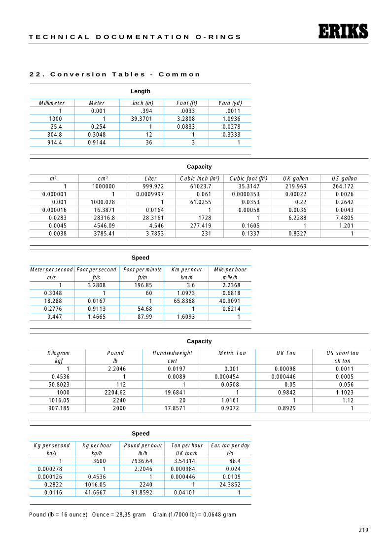
219
T E C H N I C A L D O C U M E N T A T I O N O - R I N G S
Length
Millimeter Meter Inch (in) Foot (ft) Yard (yd)1 0.001 .394 .0033 .0011
1000 1 39.3701 3.2808 1.093625.4 0.254 1 0.0833 0.0278
304.8 0.3048 12 1 0.3333914.4 0.9144 36 3 1
Speed
Meter per second Foot per second Foot per minute Km per hour Mile per hourm/s ft/s ft/m km/h mile/h
1 3.2808 196.85 3.6 2.23680.3048 1 60 1.0973 0.681818.288 0.0167 1 65.8368 40.90910.2776 0.9113 54.68 1 0.62140.447 1.4665 87.99 1.6093 1
Speed
Kg per second Kg per hour Pound per hour Ton per hour Eur. ton per daykg/s kg/h lb/h UK ton/h t/d
1 3600 7936.64 3.54314 86.40.000278 1 2.2046 0.000984 0.0240.000126 0.4536 1 0.000446 0.0109
0.2822 1016.05 2240 1 24.38520.0116 41.6667 91.8592 0.04101 1
Capacity
m3 cm3 Liter Cubic inch (in3) Cubic foot (ft3) UK gallon US gallon1 1000000 999.972 61023.7 35.3147 219.969 264.172
0.000001 1 0.0009997 0.061 0.0000353 0.00022 0.00260.001 1000.028 1 61.0255 0.0353 0.22 0.2642
0.000016 16.3871 0.0164 1 0.00058 0.0036 0.00430.0283 28316.8 28.3161 1728 1 6.2288 7.48050.0045 4546.09 4.546 277.419 0.1605 1 1.2010.0038 3785.41 3.7853 231 0.1337 0.8327 1
Capacity
Kilogram Pound Hundredweight Metric Ton UK Ton US short tonkgf lb cwt sh ton
1 2.2046 0.0197 0.001 0.00098 0.00110.4536 1 0.0089 0.000454 0.000446 0.0005
50.8023 112 1 0.0508 0.05 0.0561000 2204.62 19.6841 1 0.9842 1.1023
1016.05 2240 20 1.0161 1 1.12907.185 2000 17.8571 0.9072 0.8929 1
2 2 . C o n v e r s i o n T a b l e s - C o m m o n
Pound (lb = 16 ounce) Ounce = 28,35 gram Grain (1/7000 lb) = 0.0648 gram
220
S E A L I N G E L E M E N T S
2 3 . A p p r o v a l s a n d A c k n o w l e d g e m e n t s
• TRADE NAMES :
Viton®Viton® is a registered trademark ofDuPont Dow Elastomers.ERIKS is officially licensed by DuPontDow Elastomers to use the genuineViton® trademark.
Teflon®Teflon® is the trademark of DuPontCompany. Teflon® is the family namefor DuPont’s range of fluoropolymerssuch as FEP, PFA, and Tefzel. ERIKSis officially licensed by DuPont compa-ny to use the Genuine Teflon® trade-mark.
Kalrez® Kalrez® is a registered trademark ofDuPont Dow Elastomers. ERIKS is officially licensed by DuPont DowElastomers to use the Kalrez® trade-mark.
• HOMOLOGATIONS :
Ask for our ‘Technical books’ on:• High purity and FDA seals• Viton®• Kalrez®
KTWKTW WRCWRC DVGW ACSACSNSF KIWA
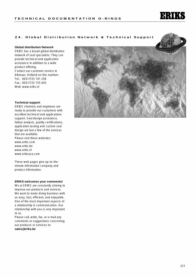
221
T E C H N I C A L D O C U M E N T A T I O N O - R I N G S
2 4 . G l o b a l D i s t r i b u t i o n N e t w o r k & T e c h n i c a l S u p p o r t
Global distribution NetworkERIKS has a broad global distributionnetwork of seal specialists. They canprovide technical and applicationassistance in addition to a wide product offering.Contact our customer service inAlkmaar, Holland on this number:Tel.: 0031/725 141 258Fax.: 0031/725 155 645Web: www.eriks.nl
Technical supportERIKS chemists and engineers areready to provide our customers withexcellent technical and applicationssupport. Seal design assistance, failure analysis, quality certifications,application testing and custom sealdesign are but a few of the servicesthat are available.Please visit these websites:www.eriks.comwww.eriks.bewww.eriks.nlwww.eriksusa.com
These web pages give up-to-the-minute information company andproduct information.
ERIKS welcomes your comments!We at ERIKS are constantly striving toimprove our products and services.We want to make doing business withus easy, fast, efficient, and enjoyable.One of the most important aspects ofa relationship is communication. Ourrelationship with you is very importantto us. Please call, write, fax, or e-mail anycomments or suggestions concerningour products or services to:[email protected]


![Augusto Cesar de O. Morgado - Analise Combinatoria e Probabilidade[p084-133]](https://img.pdfslide.us/doc/110x75/5571fc6d4979599169973c60/augusto-cesar-de-o-morgado-analise-combinatoria-e-probabilidadep084-133.jpg)