Embed Size (px)
Citation preview

CSM_K3GN_DS_E_7_2
1
1/32 DIN Digital Panel Meter
K3GN1/32 DIN Digital Panel Meter for Downsizing Equipment and Control Panels• Compact size: 48 x 24 x 82 (W x H x D).• Multi-input compatible: DC voltage/current, rotary pulse.• Two display colors (switchable): green/red.• Selectable outputs.• CE marking and UL/CSA approval.• Splash-proof construction (NEMA4X: equivalent to IP66).
Model Number Structure■ Model Number Legend
1. Input TypeND: DC voltage/current, NPNPD: DC voltage/current, PNP
2. Output TypeC: 2 relay contact outputs (SPST-NO)C-FLK: 2 relay contact outputs (SPST-NO) and RS-485C-L1: 2 relay contact outputs (SPST-NO) and DC current (0 to 20 mA, 4 to 20 mA)C-L2: 2 relay contact outputs (SPST-NO) and DC voltage (0 to 5 V, 1 to 5 V, 0 to 10 V)T1: 3 transistor outputs (NPN open collector)T1-FLK: 3 transistor outputs (NPN open collector) and RS-485T1-L1: 3 transistor outputs (NPN open collector) and DC current (0 to 20 mA, 4 to 20 mA)T1-L2: 3 transistor outputs (NPN open collector) and DC voltage (0 to 5 V, 1 to 5 V, 0 to 10 V)T2: 3 transistor outputs (PNP open collector)T2-FLK: 3 transistor outputs (PNP open collector) and RS-485
3. OptionNone: None-400: Normally energized relays
4. Supply Voltage24 VDC: 24 VDC
Refer to Safety Precautions for All Digital Panel Meters.
For the most recent information on models that have been certified for safety standards, refer to your OMRON website.
1 2 43K3GN-@@-@-@ 24 VDC

K3GN
2
Ordering Information
■ List of Models
Note: Refer to page 5 for information on models with normally energized relays.
Specifications
■ Ratings
Note: 1. A control power supply capacity greater than the rated capacity is required when the Digital Panel Meter is turned ON. Do not forget to take this into consideration when using several Digital Panel Meters. When power is supplied, all indicators will light and outputs will be OFF. When using startup compensation time operation, the display will read “00000” and all outputs will be OFF.
2. Enabled only when using DC voltage/current input. (Min.time for control signal input: 80 ms)
Supply voltage
Input type Output type Model
Judgement output Data transmission output
24 VDC DC voltage, DC current, or NPN input
2 relay contact outputs (SPST-NO)
None K3GN-NDC 24 VDC
RS-485 K3GN-NDC-FLK 24 VDC
DC current (0 to 20 mA, 4 to 20 mA) K3GN-NDC-L1 24 VDC
DC voltage (0 to 5 V, 1 to 5 V, 0 to 10 V) K3GN-NDC-L2 24 VDC
2 relay contact outputs (SPST-NO)Normally energized relays (See note.)
None K3GN-NDC-400 24 VDC
RS-485 K3GN-NDC-FLK-400 24 VDC
DC current (0 to 20 mA, 4 to 20 mA) K3GN-NDC-L1-400 24 VDC
DC voltage (0 to 5 V, 1 to 5 V, 0 to 10 V) K3GN-NDC-L2-400 24 VDC
3 transistor outputs (NPN open collector)
None K3GN-NDT1 24 VDC
RS-485 K3GN-NDT1-FLK 24 VDC
DC current (0 to 20 mA, 4 to 20 mA) K3GN-NDT1-L1 24 VDC
DC voltage (0 to 5 V, 1 to 5 V, 0 to 10 V) K3GN-NDT1-L2 24 VDC
DC voltage, DC current, or PNP input
2 relay contact outputs(SPST-NO)
None K3GN-PDC 24 VDC
RS-485 K3GN-PDC-FLK 24 VDC
3 transistor outputs (PNP open collector)
None K3GN-PDT2 24 VDC
RS-485 K3GN-PDT2-FLK 24 VDC
Item K3GN-NDWith DC voltage, DC current, and NPN input
K3GN-PDWith DC voltage, DC current, and PNP input
Supply voltage 24 VDC
Operating voltage range 85% to 110% of the rated supply voltage
Power consumption (at max. load) (See note 1.) 2.5 W max. (at max. DC load with all indicators lit)
Input signal DC voltage, DC current, no-voltage contact, open collector
DC voltage/current input
A/D conversion Double integral method
Pulse signal input Pulse measurement method
Periodic measurement method
External power supply None
Control input Present value hold or forced zero (selectable) (See note 2.)
Outputs(Outputs depend on the model.)
Relay contact output 1 A, 30 VDC (resistive load), mechanical life: 50,000,000 operations min., electrical life: 100,000 operations min.
Transistor output Max. load voltage: 24 VDC, Max. load current: 50 mA, Leakage current: 100 μ A max.
Communications output RS-485 (2-wire, half-duplex)
Linear output DC current (0 to 20 mA DC, 4 to 20 mA: Load: 500 Ω max., Resolution: Approx. 10,000)DC voltage (0 to 5 VDC, 1 to 5 VDC, 0 to 10 VDC: Load: 5k Ω min., Resolution: Approx. 10,000)
---
Display Negative LCD (backlit LCD) display7-segment digital display, character height: 7.0 mm, and single illuminated display
Main functions Scaling, prescaling, teaching, average processing, forced zero, display color selection, output type selection, key protection, startup compensation timer, hysteresis
Ambient temperature Operating: −10°C to 55°C (with no condensation or icing)Storage: −25°C to 65°C (with no condensation or icing)
Ambient humidity Operating: 25% to 85%
Altitude 2,000 m max.
Accessories Rubber packing, fixture, operation manual

3
K3GN
■ Characteristics
■ Input Ranges: Measurement Range and Accuracy
Note: The shaded ranges indicate default settings.
Item K3GN-NDWith DC voltage, DC current, and NPN input
K3GN-PDWith DC voltage, DC current, and PNP input
Input signal DC voltage/current (4 to 20 mA, 1 to 5 V, ±5 V, ±10 V)No-voltage contact (30 Hz max. with ON/OFF pulse width of 16 ms min.)Open collector (5 kHz max. with ON/OFF pulse width of 90 μs min.)
Displayable range 5 digits (-19999 to 99999)
Sampling period 250 ms
Display refresh period Sampling period: 250 ms (at 4 Hz min.), 250 × Number of averaging times (ms) (with average processing selected), Input pulse cycle (at less than 4 Hz): Input pulse cycle × Number of averaging times
Comparative output response time(transistor outputs)
750 ms max. (transistor output)(The time required for the judgment output to be output if the input signal rapidly changes from 15% to 95% or from 95% to 15%.)
Linear output response time 750 ms max. (The time required for the analog output to be output if the output signal rapidly changes from 15% to 95% or from 95% to 15%.)
---
Insulation resistance 20 MΩ min. (at 500 VDC) between external terminal and case.Insulation provided between inputs, outputs, and power supply.
Dielectric strength 1,000 VAC for 1 min between external terminal and case.
Noise immunity ±480 V on power supply terminals in normal mode, ±1,500 V in common mode, ±1 μs, or 100 ns for square-wave noise with 1 ns
Vibration resistance Vibration frequency: 10 to 55 Hz, 0.35-mm half amplitude for 10 min each in X, Y, and Z directions
Shock resistance Models with transistor outputs: 150 m/s2 three times each in 3 axes, 6 directionsModels with contact outputs: 100 m/s2 three times each in 3 axes, 6 directions
Weight Approx. 100 g (Main Unit only)
Degree of protection
Front panel NEMA4X for indoor use (equivalent to IP66),
Rear case IP20
Terminals IP00 and finger protection (VDE0106/100)
Memory protection Non-volatile memory (EEPROM) (possible to rewrite 100,000 times)
Approved standards UL508, CSA C22.2 No. 61010-1
EMC (EMI) EN 61326-1 Industrial electromagnetic environmentEmission Enclosure: EN55011 Group 1 class A(EMS) EN 61326-1 Industrial electromagnetic environmentImmunity ESD: EN 61000-4-2: 4 kV (contact discharge)
8 kV (air discharge)Immunity RF-interference: EN 61000-4-3: 10 V/m (amplitude-modulated,
80 MHz to 1 GHz)Immunity Fast Transient Noise: EN 61000-4-4: 2 kV (power line)Immunity Burst Noise: 1 kV line to line (I/O signal line)Immunity Surge: EN 61000-4-5: 1 kV line to ground (power line)Immunity Conducted Disturbance EN 61000-4-6: 3 V (0.15 to 80 MHz) Immunity Power Frequency Magnetic EN 61000-4-8: 30 A/m (50 Hz) continuous time
Input type
in-t
Analog
analg
Pulse
pulse
Remote
rmt
DC current input
DC voltage input Rotary pulse
Analog range
range
4 to 20 mA
4-20
Analog range
range
1 to 5 V
1-5
±5 V
5
±10 V
10
Pulse frequency
p-fre
30 Hz
30
5 kHz
5k
Range of display from :9999 to 99999 using communications.
Connection terminal
E-F Connection terminal
D-E Connection terminal
B-C
Input impedance
60 Ω Input impedance
1 MΩ min. --- ---
Measurement accuracy
±0.1% full scale ± one digit max. (at 23±3°C)
±0.1% full scale ± one digit max. (at 23±5°C)
±0.1% full scale ± one digit max. (at 23±5°C)
---
Current range (mA) 20.00
4.00
0.00
Voltagerange (V)10.00
5.000
0.000
−5.000
−10.00
Frequency range(Hz)
5000
4000
3000
2000
1000
0.0
5.500
0.000
5.500
−5.500
22.00
0.00
11.00
−11.00
30.00
0.05
5000
0.05

K3GN
4
■ Input/Output Ratings
Relay Contact Output
Transistor Output
Communications Specifications
Linear Output
Item Resistive load (cosφ = 1)Rated load 1 A at 30 VDCRated through current 1 A max. (at COM terminal)Min. permissible load (P level, reference value)
10 mV, 10 μA
Mechanical life 50,000,000 operations min.Electrical life 100,000 operations min.
Rated load voltage 24 VDCMax. load current 50 mALeakage current 100 μA max.
Item RS-485Communications method 2-wire, half-duplexSynchronization method Start-stop synchronizationBaud rate 1,200/2,400/4,800/9,600/19,200 bpsTransmission code ASCIICommu-nications
Reading/Writing to the K3GN
Read/write comparative set values, read/write scaling values, enable/disable the writing of data through communications, forced-zero control, and other data.
Item 0 to 20 mA
4 to 20 mA
0 to 5 V 1 to 5 V 0 to 10 V
Permissible load impedance
500 Ω max. 5 kΩ min.
Resolution Approx. 10,000Output error ±0.5% full scale ±0.5 full scale.
±0.15 V at 1 V or less (no output for 0 or less)

5
K3GN
Nomenclature
Name Functions1. Main display Displays process values, parameters, and set values.2. Status indicators OUT1 Lit when output 1 is ON.
OUT2 Lit when output 2 is ON.SV Lit when a set value is being displayed or changed.T Lit when the teaching function is enabled. Flashes when the K3GN is in teaching operation.
Lit when a calibration value is being displayed during user calibration. Flashes while reading a calibra-tion value.
ZERO Lit while the forced-zero function is activated.HOLD Lit when HOLD input is ON.CMW Lit when communications writing is “enabled” and is out when it is “disabled.”
3. Level indicator Displays the current level that the K3GN is in. (See below for details.)4. Level Key Used to change the level.5. Mode Key Used to allow the Main display to indicate parameters sequentially.6. Shift Key Used to enable that set value to be changed. When changing a set value, this key is used to move
along the digits.7. Up/Zero Key Used to change a set value. Used to set or clear a forced-zero function when a measurement value is
being displayed.
1. Main display
2. Status indicators
3. Level indicator
4. Level key
2. Status indicators
7. Up/Zero key6. Shift key5. Mode key
Level indicator Level
p Protect
Not lit Operation
a Adjustment
s Initial setting
c Communications setting
f Advanced function setting
u User calibration
Models with Normally Energized RelaysK3GN-NDC-@-400 24 VDC• The drive operation for the output relay is reversed in these models.• Relay contacts can be made open (i.e., OFF) when comparative set
values are being judged. This is effective when constructing systemsthat take failsafe measures into consideration.
List of ModelsModels with Normally Energized Relays
K3GN-NDC-400 24 VDCK3GN-NDC-FLK-400 24 VDCK3GN-NDC-L1-400 24 VDCK3GN-NDC-L2-400 24 VDC
Relation between Output Type and Relay Output Operation
HysteresisSet value
Measurement value
OutputON
OFF
HysteresisUpper-limit
set value
Lower-limit set value
Measurement value
OutputON
OFF
Hysteresis
Hysteresis
Set value
Measurement value
OutputON
OFF
Upper limit
Lower limit
Upper and lower limits
Note: If Upper/Lower Limit is selected, theupper limit and lower limit for the com-parative set value can be set individu-ally and will be displayed for OUT1and OUT2.

K3GN
6
Connections
■ Terminal Arrangement
Terminal No. Name Description
A-B Operation power Connect the operation power supply.
C-B Event input or pulse/contact input Operates as follows depending on parameter setting:• Holds process value.• Calibrate the process value to zero and clear
the forced-zero function.• Pulse or contact input.
C-A
D,F-E Analog input Connect the voltage or current analog input.
G-H Communications RS-485 communications terminals.
Linear output 0 to 20 mA DC, 4 to 20 mA DC
0 to 5 VDC, 1 to 5 VDC, 0 to 10 VDC
I,K-L Outputs Outputs relay or transistor outputs. There is also a PASS output for models with transistor outputs.
I,J,K-L
B (+) A (−)
7 8
7 8C
1 2 3
1 2 3A
9 10 11 12
9 10 11 12
9 10 11 12
D
4 5 6B
C D
A B
7 8 9 10 11 12
1 2 3 4 5 6
Output terminals
Input terminals
NC NC
RS-485
Mod
els
with
NP
N in
puts
Mod
els
with
PN
P in
puts
OUT1
PASS
NC
OUT2
COM
OUT1
OUT2
COM
OUT1 PASS OUT2 COM
Voltage CurrentAnalog input
COM
Event or pulse/contact input
Event or pulse/contact input
Ana
log
inpu
t
Mod
els
with
out
com
mun
icat
ions
Mod
els
with
co
mm
unic
atio
ns
Operation power supply 24 VDC
Operation power supply 24 VDC
Mod
els
with
PN
P tr
ansi
stor
out
puts
Mod
els
with
NP
N tr
ansi
stor
out
puts
Mod
els
with
re
lay
outp
uts
(+) (−)
7 8
Mod
els
with
lin
ear
outp
ut
7
K3GN
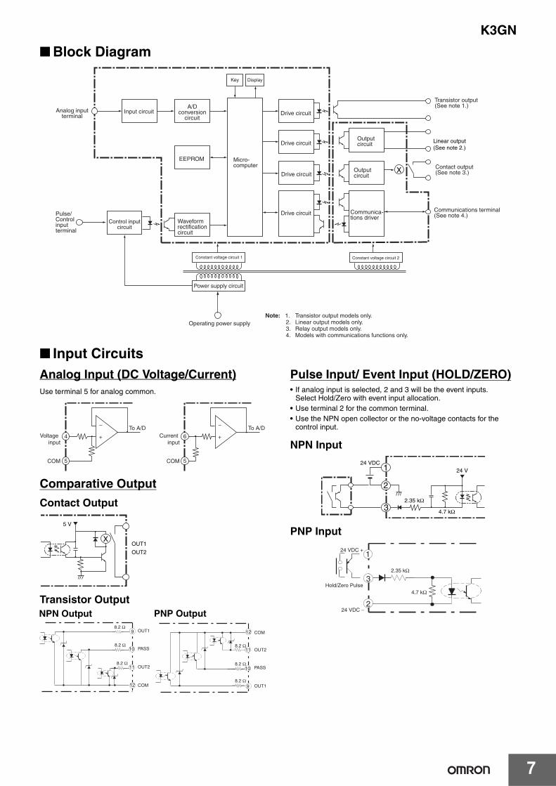
■ Block Diagram
■ Input CircuitsAnalog Input (DC Voltage/Current)Use terminal 5 for analog common.
Comparative Output
Contact Output
Transistor Output
Pulse Input/ Event Input (HOLD/ZERO)• If analog input is selected, 2 and 3 will be the event inputs.
Select Hold/Zero with event input allocation. • Use terminal 2 for the common terminal. • Use the NPN open collector or the no-voltage contacts for the
control input.
NPN Input
PNP Input
DisplayKey
Drive circuit
Drive circuit
Drive circuit
Constant voltage circuit 1
Power supply circuit
Input circuit
Operating power supply
Constant voltage circuit 2
EEPROM
Analog input terminal
Pulse/ Control input terminal
Control input circuit
A/D conversion
circuit
Waveform rectification circuit
Micro-computer
Note: 1. Transistor output models only. 2. Linear output models only. 3. Relay output models only. 4. Models with communications functions only.
Communica-tions driver
Transistor output (See note 1.)
Contact output (See note 3.)
Communications terminal (See note 4.)
X
Linear output(See note 2.)
Output circuit
Output circuitDrive circuit
Voltage input
COM
To A/D −
+ Current input
COM
To A/D −
+ 6
5
4
5
X
5 V
OUT1
OUT2
9
10
11
12
8.2 Ω
8.2 Ω
8.2 Ω
OUT1
OUT2
PASS
COM 9
10
11
12
8.2 Ω
8.2 Ω
8.2 Ω
OUT1
OUT2
PASS
COM
NPN Output PNP Output
1
2
32.35 kΩ
4.7 kΩ
24 VDC24 V
3
4.7 kΩ
2.35 kΩ
2
24 VDC +
24 VDC −
1
Hold/Zero Pulse

K3GN
8
Linear Output
Note: The commons for linear output and transistor output on models with L1 and L2 are connected internally.Depending on how the common is wired for externally connected devices, unwanted current paths for the linear output signal in the circuit may prevent the output signal from being output.When connecting an external device, externally connect a relay to the transistor output or provide another means of insulation.
−
+7
+
−
5 kΩ min.
8L
−
+7+
−
500 Ω max.
Linear voltage output Linear current output
8L

9
K3GN
Operating Procedures
■ Initial Setting FlowchartInput Type
Note: The default value is analg: Analog input.
Analog Input TypeK3GN-ND@
Note: The default value is 4-20: 4 to 20 mA input range.
K3GN-NL@ (with Microvoltage Input)
Note: The default value is 199.9: ±199.9 mV input range.
Pulse Frequency
Note: The default value is 5k: 5 kHz input range.
Setting ScalingAnalog Input Signal
(Refer to page 10 if a pulse input is selected.)
• The scaling will be displayed on a line connecting two points by setting Display 1 for Input 1 and Display 2 for Input 2. The position of the decimal point can be set as desired. If the decimal point is to be displayed, it is necessary to consider the number of digits to be displayed past the decimal point when setting the scaling display value.Note: When pulse input is used, the base point is the 0 point, so the settings are only the input value and the display value.
Input type Parameter Function
Analog analg Selects the DC voltage/current signal input.
Pulse pulse Selects the pulse input signal.
Remote rmt Displays the communications remote data from the Programmable Controller.
Input specification Parameter Setting range
4 to 20 mA 4-20 Values from −19999 to 99999 can be displayed with scaling.The position of the decimal point can be set as desired.1 to 5 V 1-5
±5 V 5
±10 V 10
Input specification Parameter Setting range
±199.9 mV 199.9 Values from −19999 to 99999 can be displayed with scaling. The position of the decimal point can be set as desired. ±19.99 mV 19.99
Input specification Parameter Setting range
0.05 Hz to 30.00 Hz 30 Values from −19999 to 99999 can be displayed with scaling. The position of the decimal point can be set as desired.0 Hz to 5 kHz 5k
Instead of setting by inputting with the Shift Key and Up Key, current measurement values van be input as scaling input values for teaching. This is useful for making settings while checking the operation status of the K3GN.For details on the operating procedures, refer to the K3GN Digital Panel Meter Manual (Cat. No. N102).
Input value
Displayed value
Input value
Displayed value
Input 1 Input 2
Display 1
Display 2
Input 1Input 2
Display 1
Display 2
Power ON
Operation
Press the Level Key for 3 s min. to move to the initial setting level.
Select the input type and analog type (or pulse frequency).
Set the scaling value and output type if required.
Press the Level Key for 1 s min. to return to the operation level.
Set the values for OUT1 and OUT2.
If required, move to the advanced setting level and set parameters,such as the average processing,event input assignment, hysteresis value, auto-zero time, startup compensation time, and display color change.
For models with communications, press the Level Key for less than 1 s to move to the communications setting level.
Set the communications specification and press the Level Key for less than 1 s to move to the initial setting level.

K3GN
10
• If the K3GN is used with a pulse signal input, the display value will be the input frequency if scaling is not performed. Display the rate of rotation or the speed of a device or machine to which the K3GN is mounted by converting using scaling.The relation between input f (Hz) and display D is expressed in the form D = f x a (factor). The value depends on the display unit. The formula will be comprised as follows:Display using rpm: D = f x 1/N x 60, N = Number of pulses per rotation, f = Input pulse frequency (Hz) (i.e., number of pulses in one second)Display using m/min: D = f x π d x 1/N x 60, π d = Circumference length (m) per rotation
Output 1 Type
Note: The default value is hi: Upper limit.
Prescaling Example
To display the rotational speed of a device that outputs five pulses per rotation:
D = f × 1/5 × 60, and,
If f=1,
D = 12, so
The setting will be completed by inputting inp:1 and dsp:12.
Output 2 Type
Note: The default setting is lo: Lower limit.
The output operations can be selected separately for OUT1 and OUT2.
Output type
Parameter Function
Upper limit hi Output turns ON if the measurement value ≥ comparative set value 1.
Lower limit lo Output turns ON if the measurement value ≤ comparative set value 1.
Upper and lower limits
hi-lo The comparative upper-limit set value and comparative lower-limit set value can be set separately and expressed high and low.Output turns ON if the measurement value ≥ comparative upper-limit set value 1 or if the measurement value is ≤ comparative lower-limit set value 1.
Input value f (Hz)00
Display value D
Input value
Display value
Output type
Parameter Function
Upper limit hi Output turns ON if the measurement value ≥ comparative set value 2.
Lower limit lo Output turns ON if the measurement value ≤ comparative set value 2.
Upper and lower limit
hi-lo The comparative upper-limit set value and comparative lower-limit set value can be set separately and expressed high and low.Output turns ON if the measurement value ≥ comparative upper-limit set value 2 or if the measurement value is ≤ comparative lower-limit set value 2.
K3GN
Pulse
HysteresisComparative set value
Measurement value
Comparative outputON
OFF
HysteresisComparative set value
Measurement value
Comparative outputON
OFF
HysteresisComparative
upper-limit set value
Comparative lower-limit set value
Measurement value
Comparative outputON
OFF
Hysteresis
Upper Limit Lower Limit Upper and Lower Limits
ONOFF
ONOFF
ONOFF
ONOFF
ONOFF
ONOFF
ONOFF
ONOFF
Comparative set value 2
Comparative set value 1
Comparative 2 output
Comparative 1 output
ONOFF
PASS(Transistor output models only)
Comparative upper-limit set value 2
Comparative upper-limit set value 1Comparative lower-limit set value 1Comparative upper-limit set value 2
Comparative 2 outputComparative 1 output
Comparative upper-limit set value 2
Comparative upper-limit set value 2
Comparative set value 1
Comparative 2 output
Comparative 1 output
PASS(Transistor output models only)
PASS(Transistor output models only)
Upper Limit 2-stage Output Threshold Output Combination of Upper Limit and Upper/Lower Limits

11
K3GN
Linear Output Type Linear output
typeParameter Meaning of set value
Linear current type
0-20 Linear current type: 0 to 20 mA
4-20 Linear current type: 4 to 20 mA
Linear voltage type
0-5 Linear voltage type: 0 to 5 V
1-5 Linear voltage type: 1 to 5 V
0-10 Linear voltage type: 0 to 10 V

K3GN
12
Setting Menu and Parameters
key less than 1 sOperation level
Power ON
Power ON
Operation level Adjustment level
Communications setting level
Protect
Initial setting level
Advanced function setting level
Calibration level
Adjustment level
Select either.
Present value
Comparative set value 1 to
to
to
to
to
to
Comparative upper-limit set value 1
Comparative lower-limit set value 1
Comparative set value 2
Comparative upper-limit set value 2
Comparative lower-limit set value 2
Communications writing /
Select either.
To the next parameterSV will flash.
If 5 s lapses without any key being pressed, the set value will be registered, and the system will return to monitor status.
Change the set value using the Keys.
Measurement in progress
Measurement stopped
Not displayed for some models.
Level change
keyless than 1 s
keyless than 1 s
key3 s min.
key1 s min.
key1 s min.
Password input
Password input
+ key
at least the user-set time
+ keys
1 s min.
Changing Set Values
While the parameter is being displayed, press the Key to display the set value. Monitor StatusPress the Key again to enter the status for setting. Setting StatusThe part to be changed will flash.Make the required setting, then press the Key. The system will switch to the next parameter and the set value will be registered.
Monitor status Setting status
Measurement is stopped in the setting level.At that time all outputs will turn OFF.
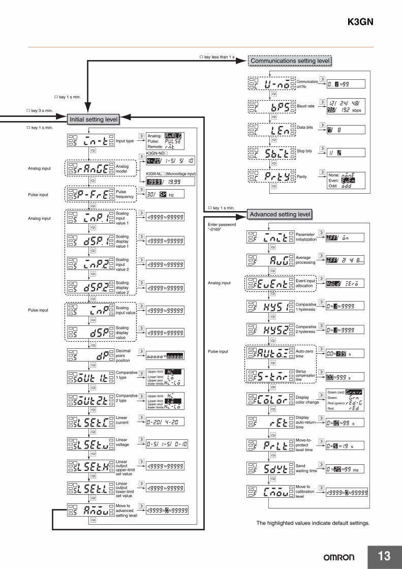
13
K3GN
key 1 s min.
key 1 s min.
key 3 s min.
Analog input
Analog input
Pulse input
Pulse input
Input type
Analogmodel
Pulsefrequency
Scalinginput value 1
Scalingdisplay value 1
to
to
to
to
to
to
to
to
Scalinginput value 2
Scalingdisplay value 2
Scalinginput value
Scaling display value
Decimal point position
to
Comparative 1 type
Comparative 2 type
Move to advanced setting level
to to
Initial setting level
Communications setting level
Advanced setting level
Communications unit No.
to
Baud rate //
/
/ /
Data bits
/Stop bits
Parity
,
kbps
key 1 s min.
Analog input
Enter password"-0169"
Pulse input
Parameter initialization
Average processing
Event inputallocation
Comparative 1 hysteresis
Comparative 2 hysteresis
Auto-zero time
Startup compensation time
Display color change
Display auto-return time
Move-to-protect level time
to to
Send waiting time to to
Move to calibration level
None:Even:Odd:
Analog:Pulse:Remote:
/
/
/
/
/
/ /
/
Hz
Upper limit:
Lower limit:Upper and lower limits:
Upper limit:
Lower limit:Upper and lower limits:
Green (red):
Green:
Red (green):
Red:
/
/
/
/ /
ms
s
to to s
to s
s
to to
to to
to
times
The highlighted values indicate default settings.
key less than 1 s
to to
Linear current
Linear voltage
Linear outputupper-limit set value
Linear outputlower-limit set value
K3GN-ND@
K3GN-NL@ (Microvoltage input)
K3GN
14
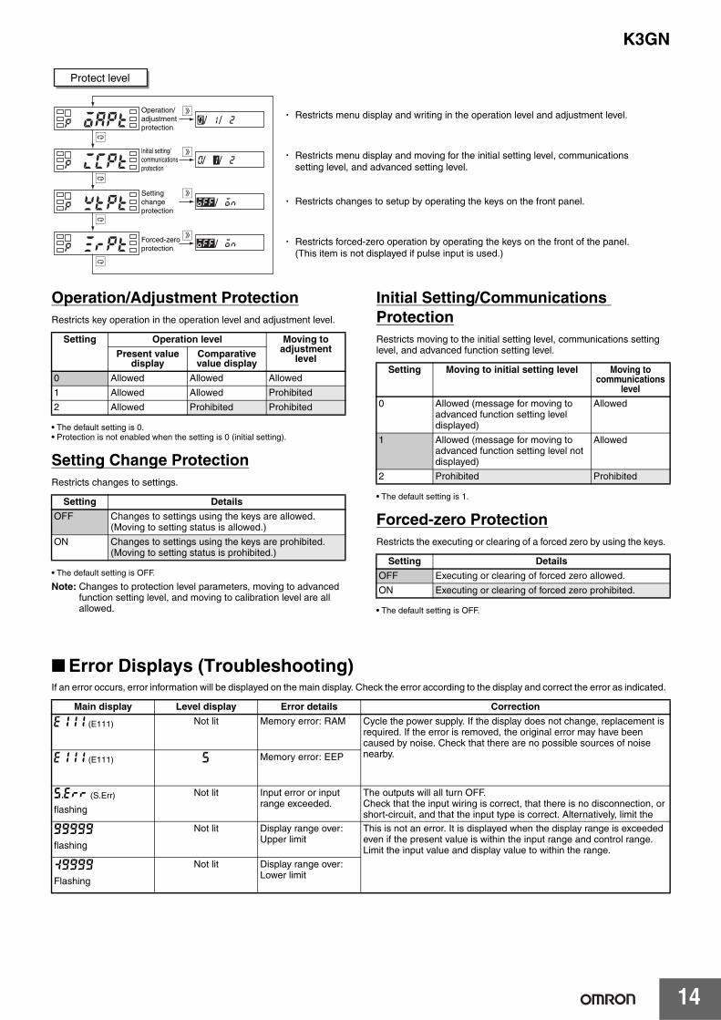
Operation/Adjustment ProtectionRestricts key operation in the operation level and adjustment level.
• The default setting is 0.• Protection is not enabled when the setting is 0 (initial setting).
Setting Change ProtectionRestricts changes to settings.
• The default setting is OFF.
Note: Changes to protection level parameters, moving to advanced function setting level, and moving to calibration level are all allowed.
Initial Setting/Communications ProtectionRestricts moving to the initial setting level, communications setting level, and advanced function setting level.
• The default setting is 1.
Forced-zero ProtectionRestricts the executing or clearing of a forced zero by using the keys.
• The default setting is OFF.
■ Error Displays (Troubleshooting)If an error occurs, error information will be displayed on the main display. Check the error according to the display and correct the error as indicated.
Protect level
Operation/adjustmentprotection
Initial setting/communicationsprotection
/ /
Setting changeprotection
Forced-zeroprotection
/
/
/ / Restricts menu display and moving for the initial setting level, communications setting level, and advanced setting level.
Restricts changes to setup by operating the keys on the front panel.
Restricts forced-zero operation by operating the keys on the front of the panel.(This item is not displayed if pulse input is used.)
Restricts menu display and writing in the operation level and adjustment level.
Setting Operation level Moving to adjustment
levelPresent value display
Comparative value display
0 Allowed Allowed Allowed
1 Allowed Allowed Prohibited
2 Allowed Prohibited Prohibited
Setting Details
OFF Changes to settings using the keys are allowed. (Moving to setting status is allowed.)
ON Changes to settings using the keys are prohibited. (Moving to setting status is prohibited.)
Setting Moving to initial setting level Moving to communications
level
0 Allowed (message for moving to advanced function setting level displayed)
Allowed
1 Allowed (message for moving to advanced function setting level not displayed)
Allowed
2 Prohibited Prohibited
Setting Details
OFF Executing or clearing of forced zero allowed.
ON Executing or clearing of forced zero prohibited.
Main display Level display Error details Correction
e111 (E111) Not lit Memory error: RAM Cycle the power supply. If the display does not change, replacement is required. If the error is removed, the original error may have been caused by noise. Check that there are no possible sources of noise nearby.
e111 (E111) s Memory error: EEP
s.err (S.Err)
flashing
Not lit Input error or input range exceeded.
The outputs will all turn OFF. Check that the input wiring is correct, that there is no disconnection, or short-circuit, and that the input type is correct. Alternatively, limit the
99999
flashing
Not lit Display range over: Upper limit
This is not an error. It is displayed when the display range is exceeded even if the present value is within the input range and control range.Limit the input value and display value to within the range.
:9999
Flashing
Not lit Display range over: Lower limit

15
K3GN
Operation
■ Main Functions
ScalingThe K3GN includes a scaling function that can convert the input signal to a desired value and display that value.
The displayed values can be freely adjusted to shift values, to create reversed displays, or to create positive/negative displays.
TeachingTeaching is used when using scaling or setting comparative set values to set the present measurement values as the set values instead of inputting with the Shift and Up/Zero Keys. Teaching is useful for making settings while checking the operation status of the K3GN.
Average ProcessingAverage processing can be performed for measurement values using four levels (OFF, 2 times, 4 times, or 8 times). Average processing stabilizes displayed values by averaging the corresponding input signals that fluctuate dynamically. Select the appropriate number of averaging times depending on the application.
Forced-zero FunctionIt is possible to shift from a value to the zero point with one touch of the Up/Zero Key on the front panel (for example, when adjusting reference values).
Note: This function can be used only when forced-zero operation protection is released.
Changing the Display ColorThe color of the value displayed can be set to either red or green.Make the setting according to the purpose and application of theequipment in which the K3GN is installed. The display color can alsobe set to change from green to red, or from red to green, accordingto the status of the comparison criteria.
Output Type SelectionOutput operation for comparative set values can be freely selected. Upper limit: Output ON if the measurement value ≥ comparative set value.Lower limit: Output ON if the measurement value ≤ comparative set value.Upper/lower limit: Output ON if the measurement value ≥ comparative upper-limit set value or if the measurement value is ≤ the comparative lower-limit value.
Key ProtectionKey protection is used to restrict changes to displays and settings using the front panel keys and to restrict menu display and movement of operation levels. This function is effective for preventing misuse during operation.
Startup Compensation Time (Rotary Pulse Input Only)The startup compensation time parameter keeps the measurementoperation from sending an unnecessary output corresponding toinstantaneous, fluctuating input from the moment the K3GN is turnedON until the end of the preset period.
HysteresisThe hysteresis of comparative outputs can be set to prevent thechattering of relay or transistor outputs.INPUT1 INPUT2
Input value
DISPLAY1
DISPLAY2
( )( )
Displayvalue
INPUT2INPUT1Inputvalue
DISPLAY1
DISPLAY2
Displayvalue
/ZERO
-ZEROOUT1-
OUT2-
SV-
-HOLD
-CMW
K3GN

K3GN
16
DimensionsNote: All units are in millimeters unless otherwise indicated.
Installation1. Insert the K3GN into the panel cut-out hole.2. For a waterproof installation, insert the rubber gasket onto the
body of the K3GN.
3. Fit the adaptor into the grooves on the left and right sides of the rear case, then push it until it contacts the panel to secure the K3GN.
Angle of ViewThe K3GN is designed to provide the best visibility at the angles shown in the following diagram.
■ Rubber PackingThe Rubber Packing ensures a waterproof level conforming to NEMA4X. Depending on the operating environment, deterioration, contraction, or hardening of the Rubber Packing may occur, making replacement necessary. Contact your OMRON representative if replacement is required.
■ Wiring Precautions • Wire the power supply with the correct polarity. Wiring with
incorrect polarity may result in damage or burning.• Wire the terminals using crimp terminals.• Tighten terminal screws to a torque of approx. 0.5 N·m.• Wire signal lines and power lines separately to reduce the influence
of noise.
■ Wiring
Power Supply• Input 24 VDC to terminals 1 and 2.
• Use M3 crimp terminals of the type shown below.
/ZERO
-ZEROOUT1-
OUT2-
SV-
-HOLD
-CMW
T
K3GN
280
22
44.8
48
2435
Separate mounting Gang mounting
22.2+0.30 22.2
+0.30
45+0.60
(48 × No. of Panels − 2.5) +1.00
40 min.The products cannot be made waterproof when gang-mounted.
---- -
-
7 mm
3.6 mm
Main Display Character Size
The K3GN uses M3 terminals. A terminal cover is provided.
Panel Cutout DimensionsK3GN
• For installation, insert the K3GN panel into the rectangular hole, insert the adaptor from the rear, and push it in to reduce the gap between the panel surface and the adaptor. Secure the Unit with the screws. For water-proof installation, insert the rubber gasket onto the body of the K3GN.
• If multiple mounted Units are used, make sure the ambient temperature for the K3GN does not exceed the specified temperature.
Mounting Recommended Panel Thickness 1 to 5 mm.Mount the product horizontally.
Rubber packing
Adaptor
20°
40°
1
2
24 VDC
5.8 mm max.
5.8 mm max.

17
K3GN
Measurement InputThe following table shows the relation between input ranges and
input terminals.
Input range Input terminals
DC voltage/DC current 4 to 20 mA E-F
1 to 5 V D-E
±5 V
±10 V
No-voltage contacts and NPN open collector(Models with NPN inputs)
B-C
No-voltage contacts and PNP open collector(Models with PNP inputs)
A-C
Be sure to read the Precautions for Correct Use and other information required when using the K3GN in the following user’s manual.K3GN Digital Panel Meter User’s Manual (Cat.No. N102)
In the interest of product improvement, specifications are subject to change without notice.
ALL DIMENSIONS SHOWN ARE IN MILLIMETERS.
To convert millimeters into inches, multiply by 0.03937. To convert grams into ounces, multiply by 0.03527.
Terms and Conditions Agreement Read and understand this catalog. Please read and understand this catalog before purchasing the products. Please consult your OMRON representative if you have any questions or comments. Warranties. (a) Exclusive Warranty. Omron’s exclusive warranty is that the Products will be free from defects in materials and workmanship for a period of twelve months from the date of sale by Omron (or such other period expressed in writing by Omron). Omron disclaims all other warranties, express or implied. (b) Limitations. OMRON MAKES NO WARRANTY OR REPRESENTATION, EXPRESS OR IMPLIED, ABOUT NON-INFRINGEMENT, MERCHANTABILITY OR FITNESS FOR A PARTICULAR PURPOSE OF THE PRODUCTS. BUYER ACKNOWLEDGES THAT IT ALONE HAS DETERMINED THAT THE PRODUCTS WILL SUITABLY MEET THE REQUIREMENTS OF THEIR INTENDED USE. Omron further disclaims all warranties and responsibility of any type for claims or expenses based on infringement by the Products or otherwise of any intellectual property right. (c) Buyer Remedy. Omron’s sole obligation hereunder shall be, at Omron’s election, to (i) replace (in the form originally shipped with Buyer responsible for labor charges for removal or replacement thereof) the non-complying Product, (ii) repair the non-complying Product, or (iii) repay or credit Buyer an amount equal to the purchase price of the non-complying Product; provided that in no event shall Omron be responsible for warranty, repair, indemnity or any other claims or expenses regarding the Products unless Omron’s analysis confirms that the Products were properly handled, stored, installed and maintained and not subject to contamination, abuse, misuse or inappropriate modification. Return of any Products by Buyer must be approved in writing by Omron before shipment. Omron Companies shall not be liable for the suitability or unsuitability or the results from the use of Products in combination with any electrical or electronic components, circuits, system assemblies or any other materials or substances or environments. Any advice, recommendations or information given orally or in writing, are not to be construed as an amendment or addition to the above warranty. See http://www.omron.com/global/ or contact your Omron representative for published information. Limitation on Liability; Etc. OMRON COMPANIES SHALL NOT BE LIABLE FOR SPECIAL, INDIRECT, INCIDENTAL, OR CONSEQUENTIAL DAMAGES, LOSS OF PROFITS OR PRODUCTION OR COMMERCIAL LOSS IN ANY WAY CONNECTED WITH THE PRODUCTS, WHETHER SUCH CLAIM IS BASED IN CONTRACT, WARRANTY, NEGLIGENCE OR STRICT LIABILITY. Further, in no event shall liability of Omron Companies exceed the individual price of the Product on which liability is asserted. Suitability of Use. Omron Companies shall not be responsible for conformity with any standards, codes or regulations which apply to the combination of the Product in the Buyer’s application or use of the Product. At Buyer’s request, Omron will provide applicable third party certification documents identifying ratings and limitations of use which apply to the Product. This information by itself is not sufficient for a complete determination of the suitability of the Product in combination with the end product, machine, system, or other application or use. Buyer shall be solely responsible for determining appropriateness of the particular Product with respect to Buyer’s application, product or system. Buyer shall take application responsibility in all cases. NEVER USE THE PRODUCT FOR AN APPLICATION INVOLVING SERIOUS RISK TO LIFE OR PROPERTY OR IN LARGE QUANTITIES WITHOUT ENSURING THAT THE SYSTEM AS A WHOLE HAS BEEN DESIGNED TO ADDRESS THE RISKS, AND THAT THE OMRON PRODUCT(S) IS PROPERLY RATED AND INSTALLED FOR THE INTENDED USE WITHIN THE OVERALL EQUIPMENT OR SYSTEM. Programmable Products. Omron Companies shall not be responsible for the user’s programming of a programmable Product, or any consequence thereof. Performance Data. Data presented in Omron Company websites, catalogs and other materials is provided as a guide for the user in determining suitability and does not constitute a warranty. It may represent the result of Omron’s test conditions, and the user must correlate it to actual application requirements. Actual performance is subject to the Omron’s Warranty and Limitations of Liability. Change in Specifications. Product specifications and accessories may be changed at any time based on improvements and other reasons. It is our practice to change part numbers when published ratings or features are changed, or when significant construction changes are made. However, some specifications of the Product may be changed without any notice. When in doubt, special part numbers may be assigned to fix or establish key specifications for your application. Please consult with your Omron’s representative at any time to confirm actual specifications of purchased Product. Errors and Omissions. Information presented by Omron Companies has been checked and is believed to be accurate; however, no responsibility is assumed for clerical, typographical or proofreading errors or omissions.
2017.8
In the interest of product improvement, specifications are subject to change without notice.
OMRON Corporation Industrial Automation Company http://www.ia.omron.com/
(c)Copyright OMRON Corporation 2017 All Right Reserved.