Embed Size (px)
Citation preview

RL 550BInstruction Manual
Version 7.8
illonrecision
Products, Inc.
Manufacturers of The World's FinestLoading Equipment

RL 550B Parts ListPart # Description13149 Manual13409 Crank13573 Machine Box13583 Link Arm, Left13644 Powder Bar Spacer13650 Spent Primer Cup13673 Primer Magazine, Red, Large13691 Powder Measure Tube13700 Link Arm Pin13704 Handle Washer13707 Follower Rod13719 Cartridge Spring Retainer Screw13720 Index Sprocket13734 Parts Box 13747 Link Arm, Right w/Hook13757 Primer Seating Punch, Small13765 Roller13775 Main Shaft13781 Shellplate Platform13789 1/4-2/8 Set Screw13793 Roller13794 Shellplate Bolt13795 Machine Cover13799 Stripper Wing Nut13801 Tinnerman Nut Insert13803 Ejected Cartridge Chute Bracket13824 Primer Seating Cup, Large13825 Primer Seating Cup, Small13830 Main Shaft Pivot Pin13834 Solid Link Arm Pin, Left 13839 Cartridge Collection Bin13841 Nylock Nut13845 Collar Sleeve13848 Bellcrank Bushing13850 Operating Handle Knob13857 Battery Cover13864 Switch Lever13869 Operating Rod13871 Bellcrank Cube13879 Primer Magazine, Blue, Small13881 Hollow Link Arm Pin, Right13882 Powder Measure Lid13885 Return Bracket13887 Operating Rod Bracket13889 Primer Slide Roller13890 Spring Washer13891 Index Ball13893 Powder Bar Post, Large13898 Primer Slide Stop Nut13899 Spent Primer Catcher Chute13904 Bellcrank Bolt, New Style13909 Toolhead13917 Roller Clip13919 Slide Roller Post13920 Primer Slide13921 Powder Bar Spacer Plug13923 Brass Tip Set Screw13924 Slide Post13925 Ejector Wire13926 Cartridge Spring13928 Primer Slide Return Spring
Part # Description* 13930 Locator Buttons (3)
13939 Body Collar Clamp13940 Body Collar - Part13943 Powder Bar Bolt13951 Powder Bar Post, Small13957 Magazine Shield Cap13958 Powder Bar Bolt Washer13961 Slide Pickup Adjustment Screw13964 Retain Spring Screw13966 Shellplate Platform Bolt13967 Primer Seating Punch, Large13979 Primer Retain Pin Spring13996 Primer Punch Set Screw13997 Index Ball Spring13998 Spent Primer Catcher Pin13999 Primer Pickup Tip, Yellow, Small14001 Roller Pin14003 Flexible Orifice, Red, Large14008 Toolhead Pin14010 Primer Pickup Tip, Green, Large14013 Roller Bracket Screw 14014 Primer Housing Screw14015 Primer Track Bearing14023 8-32x3/4 BH Screw14024 Flexible Orifice, Blue, Small14025 Primer Slide Return Spring Retainer14033 Spring14037 Clamp/Bracket Screw14040 Retaining Clip14051 Primer Retaining Pin14067 Die Lock Ring14202 Powder Measure Tube Screw14280 Roller Bracket Shell Platform14281 Primer Slide Assembly, Large14282 Primer Slide Assembly, Small17085 Dispensing Tip, Large17086 Dispensing Tip, Small18086 Shoulder Washer20048 Spare Parts Kit20059 Primer Pickup Tube, Yellow, Small20060 Primer Pickup Tube, Green, Large20062 Powder Bar Assembly, Small20063 Powder Bar Assembly, Large20064 Powder Die
* 20093 Shellplate20094 Frame20263 Primer Feed Body w/ Shield20302 Primer Early Warning System20303 Powder Measure Failsafe Kit20339 Bellcrank20636 Operating Handle Assembly20782 Powder Measure System21275 Connector Body Collar22038 Crank Assembly22273 Powder Body w/ Drop Tube97000 Rod
* Indicates caliber specific parts. See the caliber conversionchart for the correct part number for the caliber you areloading for.
Some items listed are not shown in schematic illustration.
Part #13149 Spot Manuals RL550B Manual Folder 550B Manual.V7.8 9/01 WJC

14040
20059
1367313707
13794
13720
20093
13966
13925
14015
13881
14025
13928
1401413923
13747
13650
13775
13890
13409
13700
13789
13830
13890
13583
13841
13803
13839
13834
20094
13909
14067
13841
20636Assembly
13781
13885
14008
13891
13997
13930
20302See page 5 formore detail.
14280See page 5 formore detail.
See page 4 formore detail.
See page 5 formore detail.
13801
97000
18086
14033
13799
3
RL 550B Schematic
17085 (large)or
17086 (small)

13882
22273
13691
13793
14808
13940
13845
13871
97034
14041
13904
13939
14037
18086
14033
13801
13799
14067
20064
*13782
*13426
16340
14202
97000
13848
13893
20062
21353
20063
13426 * Powder Funnel, .45 cal Pistol13644 Powder Bar Spacer13691 Powder Measure Tube Only13782 * Powder Funnel, .22 cal Rifle13793 Roller13845 Collar Sleeve13848 Bellcrank Bushing13871 Bellcrank Cube13882 Powder Measure Lid13893 Powder Bar Post, Large13904 Bellcrank Screw13921 Plastic Plug13939 Body Collar Clamp13940 Body Collar - Part13943 Powder Bar Bolt13951 Powder Bar Post, Small13958 Powder Bar Bolt Washer
(not pictured)14023 8-32x3/4 BH Screw14037 Clamp/Bracket Screw14041 Bowed Washer14067 Die Lock Ring14202 Powder Measure Tube Screws14808 Collar Roller Bushing16340 10-32 Nylon Lock Nut20062 Powder Bar Assembly, Small20063 Powder Bar Assembly, Large20064 Powder Die20780 Powder Bar Assembly, Extra Small21275 Connector Body Collar - Complete21353 Powder Bar Assembly, Extra Large22273 Powder Measure, Part97034 Slotted Bellcrank20303 Powder Measure Failsafe Kit13799 Stripper Wing Nut13801 Tinnerman Nut Insert13885 Return Bracket
(not pictured– see the main schematic to identify part)
14033 Rod Spring18086 Shoulder Washer97000 Failsafe Rod
NOTE: * Indicates caliber specific parts –see the caliber conversion chart for thecorrect part number for the caliber you areloading for.
WARNINGThis powder measure drops a full charge ofpowder each time the operating handle iscycled. If, for any reason, you believe thatmore than a single measure of powder wasdropped or you think that you may havecycled the handle more than once on asingle case, you need to empty the case andstart over.A double charged case can result in bodilyinjury or a damaged firearm.
14202
139512078013644
RL 550B Automatic Powder System13921
14023
4

13757 Primer Seating Punch, Small13824 Primer Seating Cup, Large13825 Primer Seating Cup, Small13869 Operating Rod13887 Operating Rod Bracket13889 Large Roller13898 Primer Slide Stop Nut13917 Roller Clip13919 Roller Pin13920 Primer Slide13924 Primer Slide Return Spring Post13957 Primer Shield Cap13961 Slide Pickup Adjustment Screw13964 Primer Feed Stop Spring Screw13967 Primer Seating Punch, Large13979 Primer Feed Stop Spring13996 Primer Punch Set Screw14003 Flexible Orifice Large (small 14024)14010 Pickup Tube Tip Large (small 13999)14033 Primer Seating Cup Spring14037 Clamp/Bracket Screw14040 Retaining Clip14051 Primer Feed Stop Pin17085 Dispensing Tip, Large17086 Dispensing Tip, Small20263 Primer Housing and Shield22028 Primer Pickup Tube, Small22029 Primer Pickup Tube, Large22030 Primer Magazine, Small22031 Primer Magazine, Large20302 Primer Early Warning System13707 Follower Rod13857 Battery Cover13864 Switch Lever14280 Roller Bracket Assembly13719 Cartridge Spring Retaining Screw13765 Roller13899 Spent Primer Catcher Chute13926 Cartridge Spring13998 Spent Primer Catcher Pin14001 Roller Pin14530 Roller Bracket Screw(s)Complete Primer Slide Assemblies14281 Primer Slide Assembly, Large14282 Primer Slide Assembly, Small
����
5
13707
13864
20302
13957
14040
17085 (large)or
17086 (small)
20060
14010
1400320263
13967
13887
22031
13869
13857
13964
1405113979
13961
13898
13924
13919
13917
14280
14530
13899
13765
13719
1388913996
14033
13824
14037
14037
13998
14001
13920
RL 550B Automatic Primer System
13926

IntroductionFirst of all, the Dillon RL 550B is a remarkably simple
machine–a little care and thought while setting up willsave you time and give you thousands of trouble freerounds.
Suggested Minimum Equipment:1) Loading Manual 2) Powder Scale3) Safety Glasses 4) Primer Flip Tray *5) Dial Caliper * (* Indicates items that are not
absolutely essential, but are pretty darned handy!)Mounting the RL 550B to your bench.
Place your RL 550B on the edge of sturdy bench or table.Give yourself about 12 inches of work space on each side ofthe machine to allow room for components.
Using the machine itself as a template, mark and drillfour one-quarter inch holes in your bench and bolt your RL550B securely to it, Fig. 1. Next, mount the cartridgecollection bin bracket (#13803) onto your bench, Fig. 2,allowing approximately one-eighth inch clearance betweenthe platform (#13781) and the ejected cartridge chute.Using two screws or bolts, secure the bracket to yourbench. The cartridge collection bin (#13839) simply slideson the bracket, Fig. 3, and will be in the proper position tocatch ejected loaded rounds. Bolt the operating handle inplace as shown in the schematic.
Safety Points to Know Before you BeginReloading ammunition involves the use of highly
explosive primers and powder. Handling these materials isinherently dangerous. You should recognize this dangerand take certain minimum precautions to lessen yourexposure to injury.
Never operate the machine without ear and eyeprotection on. Call our customer service department at(800) 223-4570 for information on the wide variety ofshooting/safety glasses and hearing protection that Dillonhas to offer.• PAY ATTENTION: Load only when you can give yourcomplete attention to the loading process. Don’t watchtelevision or try to carry on a conversation and load at thesame time. Watch the automatic systems operate and makesure they are functioning properly. If you are interruptedor must leave and come back to your loading, alwaysinspect the cases at every station to insure that the properoperations have been accomplished.• SMOKING: Do not smoke while reloading or allowanyone else to smoke in your reloading area. Do not allowopen flames in reloading area.• SAFETY DEVICES: Do not remove any safety devicesfrom your machine or modify your machine in any way.• LEAD WARNING: Be sure to have proper ventilationwhile handling lead components or when shooting leadbullets. Lead is known to cause birth defects, otherreproductive harm and cancer. Wash your handsthoroughly after handling anything made of lead.
* Indicates a caliber specific part. See the caliber conversionchart on page 16 for the caliber you are loading for.
Fig. 2 - This photograph shows the correct mountingposition of the cartridge collection bin bracket in relationto the machine.
Fig. 1 - Using the machine as a template, mark and drillfour 1/4 inch holes allowing 12 inches on each side foryour work area.
Fig. 3 - The cartridge collection bin (#13839) simply slidesonto the bracket and will be in the proper position.
6

• LOADS AND LENGTHS: Avoid maximum loads andpressures at all times. Use only recommended loads frommanuals and information supplied by reliable componentmanufacturers and suppliers. Since Dillon Precision has nocontrol over the components which may be used on theirequipment, no responsibility is implied or assumed forresults obtained through the use of any such components.
Seat bullets as close to maximum cartridge length aspossible. Under some conditions, seating bulletsexcessively deep can raise pressures to unsafe levels. Referto a reliable loading manual for overall length (OAL).• QUALITY CHECKS: Every 50-100 rounds, performperiodic quality control checks on the ammunition beingproduced. Check the amount of powder being droppedand primer supply.• RELOADING AREA: Keep your components safelystored. Clear your work area of loose powder, primers andother flammables before loading.• COMPONENTS: Never have more than one type ofpowder in your reloading area at a time. The risk of a mix-up is too great. Keep powder containers closed.
Be sure to inspect brass prior to reloading for flaws,cracks, splits or defects. Throw these cases away.
Keep components and ammunition out of reach ofchildren.• BLACK POWDER: Do not use black powder or blackpowder substitutes in any Dillon powder measure.Loading black powder cartridges requires specializedloading equipment and techniques. Failure to do so canresult in severe injury or death.• PRIMERS: Never force primers. If they get stuck in theoperation of the machine, disassemble it and gentlyremove the obstruction.
Never attempt to clear primers that are stuck in eitherthe primer pickup tube or the primer magazine tube.Never, under any circumstances, insert any type of rod toattempt to force stuck primers out of these tubes. Trying toforce primers out of the tube will cause the primers toexplode causing serious injury or even death.
If primers get stuck in a primer magazine or pickuptube flood the tube with a penetrating oil (WD-40), throwthe tube in the garbage and call us for a free replacement.
Never attempt to deprime live primers – eventually onewill go off. When it does it will detonate the others in thespent primer cup. Depriming live primers is the singlemost dangerous thing you can do in reloading and cancause grave injury or death.• LOADED AMMUNITION: Properly label all of yourloaded ammunition (Date, Type of Bullet, Primer, Powder,Powder Charge, etc.).• BE PATIENT: Our loading equipment is conservativelyrated and you should have no trouble achieving thepublished rates with a smooth, steady hand. If somethingdoesn’t seem right, stop, look and listen. If the problem orthe solution isn’t obvious, call us. The reloading bench isno place to get into a hurry.
We have done everything we know how to make your
machine as safe as possible. We cannot, however, guaranteeyour complete safety. To minimize your risk, use commonsense when reloading and follow these basic rules.• REMEMBER: If your machine does not perform to yourexpectations, or if you are having technical difficulties, giveus a call. TO BEGIN LOADING
Now that everything is bolted down and youunderstand the safety precautions, you can proceed.
First, decide what caliber you want to reload and takethe shellplate (*#20079) from the caliber conversion box,Fig. 4. Now, in your parts box, find a bag containing; indexball (#13891), shellplate bolt (#13794), index ball spring(#13997), set screw (#13923), and index sprocket (#13720).
Insert the index ball spring (#13781) in the platform asshown in Fig. 5. Next set the index ball on top of the indexball spring. Now place the shellplate (number up) over theindex ball spring and index ball, Fig. 6.
* Indicates a caliber specific part. See the caliber conversionchart on page 16 for the caliber you are loading for.
Fig. 4 - This photo shows a complete caliber conversion;the powder funnel, shellplate and locator buttons.
Fig. 5 - This photo shows the index ball spring and indexball being placed in the platform.
7

Place the index sprocket on top of the shellplate(making sure the locator posts go into thecorresponding holes in the shellplate, see Fig. 7).
Next, insert the shellplate bolt through thesprocket and plate and into the center hole of theplatform, Fig. 8. Tighten with the supplied Allenwrench to the point where you are unable to turn thesprocket by hand. Now, back off the bolt slightly,allowing you to push the sprocket easily with yourthumb, Fig. 9. There should be no looseness or slop atthis point and when you rotate the plate, you shouldbe able to feel and hear the index ball “click” intoplace under the shellplate.
Fig. 8 - Inserting the shellplate bolt, first through the indexsprocket then the shellplate.
Fig. 7 - This photo shows the index star in its properposition: the locating tabs centered in the shellplate.
8 * Indicates a caliber specific part. See the caliber conversionchart on page 16 for the caliber you are loading for.
Fig. 6 - Showing the shellplate in its proper position:under the ejector wire with the shellplate number up.
Fig. 9 - This photo shows the proper method ofindexing the shellplate and the proper installation ofthe locator buttons.

Take the brass tipped set screw (#13923) insertand tighten securely in the tapped hole beneath theplatform on the left side of the main shaft, Fig. 10.This will keep the shellplate from tightening as youuse the machine. This screw must be loosened whenchanging calibers, something that is often forgottenas it’s out of sight.
In your caliber conversion box, you will find threebrass locator buttons. These simply drop into the threeremaining holes in the platform, Fig. 9. These“buttons” hold the cases securely in place while youare reloading, but by removing them, allow you to takeout a troublesome case, should that occur in yourreloading process.
What Primer Size?Your RL 550B has been shipped to you with the
primer system installed and correctly adjusted to feedlarge primers. If the caliber you have selected to startwith requires small primers, you must change to thesmall primer slide bar.
Observe carefully how the factory-adjusted bar fits,Fig. 11. Raise and lower the platform and notice thealignment of the primer seating cup (*#13824) as itenters the platform. This adjustment is made byturning the cap screw (#14037) on the primer feedbody, Fig. 12. Now remove the two screws frombeneath the frame under the primer feed body, Fig. 13.Unhook the spring and remove the primer slide. Toreplace, reverse this procedure.
* Indicates a caliber specific part. See the caliber conversionchart on page 16 for the caliber you are loading for.
Fig. 11 - This is the proper alignment of the operating rodand the position of the primer slide fully forward with theprimer seating cup in the lowered platform.
Fig. 12 - The operating rod has moved the primer slideinto the primer feed body where it will automaticallypick up a primer.
Fig. 10 - Insert the brass tipped set screw (#13923) andtighten securely.
Fig. 13 - Removing the primer feed body to change primerslides. Caution do not over tighten these bolts (#14014).
9
This set screw (#13961) adjuststhe outward travel of the primerslide to align the primer seatingcup with the primer magazine.

The operating rod (#13869) must be installedbetween the two white rollers before the operation ofthe primer slide. Refer to Fig. 12 for the properplacement of the rod. Unscrew the knurled cap(#13957) and remove the large primer magazine andreplace with the small primer magazine tube, Fig. 14;the plastic tip should look like the one you just tookout. Replace the knurled cap.
Wait until you’ve finished assembly before actuallyplacing primers in the magazine.
You will notice that the primer magazine tube tipsare different colors and have an indexing ridge on thetip. The magazine tips and the primer pick-up tube tipsare color coded to help identify their size, see page 13for more information. The indexing ridge is to helpyou place the magazine in its proper position in theprimer feed body.
The ToolheadYour new RL 550B has been shipped to you with
one removable toolhead. Additional toolheads areavailable from the factory.
The advantage of this system is simple, once your
dies have been adjusted just the way you want them,they can stay that way. Plus, changing to anothercaliber becomes a simple matter of pulling two pinsand sliding the toolhead out, Fig. 15.
Choose Your DiesYour RL 550B will perform well with any
manufacturer’s standard 7/8 x 14 die. However, forease of use in your RL 550B, the dies should have aradius on the lead-in portion of the die; that is to saya taper or funnel effect to assist the entrance of thecase into the die. This is especially recommended onthe sizing die.
We also recommend the use of separate bulletseating and crimp dies for pistol cases. Simultaneousseating and taper crimping of semi-auto cases is notrecommended. Why?
Two reasons. First, in a combination seating andcrimping die, we have two forces that are opposed toone another. That is, forcing the bullet into the casewhile trying to simultaneously crimp it in place.
A better idea is to seat the bullet in one die and thencrimp it in place in another. With semi-auto cases(9mm & .45 ACP) you must use a separate taper crimpdie to get reliable ammunition and function from yoursemi-automatic pistol. This type of crimp is necessaryto maintain the square shoulder effect where the brassedge of the case meets the bullet. It is on this tinyshoulder that the functioning of your semi-auto pistoldepends. If this shoulder is rounded or roll-crimped,the cartridge may enter too far into your pistol’schamber and jams will result. On revolverammunition, where the cartridge headspaces on therim of the case, this type of crimp is not as important,but once again, by using a separate crimp die, you willobtain better and more uniform bullet seating.
Carbide Dies?All Dillon pistol resizing dies are manufactured
with a carbide insert. Carbide is one of the world’shardest materials and will last the average reloader alifetime. It also takes a high polish and being moredense is smoother than a steel die. Besides itslongevity, it has another advantage. All steel diesrequire lubrication of your brass before resizing, butwith a carbide pistol resizing die this is not absolutelynecessary. Lubrication will make sizing easier, butwith a carbide pistol die, it is not required.
However, when using carbide rifle dies, your casesmust always be lubricated.
The advantage of carbide rifle dies is their long lifeand scratch resistant qualities. If you are a commercialreloader, you may want to consider them.
Setting your Pistol DiesIf you’re setting up rifle dies, use the separate
instruction booklet supplied with the dies.
Before you begin, make sure that the toolhead issecured by the toolhead pins (#14008).
* Indicates a caliber specific part. See the caliber conversionchart on page 16 for the caliber you are loading for.
Fig. 15 - A complete, removable toolhead with all of thedies adjusted. Toolhead stand is optional.
Fig. 14 - The machine comes with two primer pickup tubes(#20060 Lg, #20059 Sm) and two primer magazine tubes(#22031 Lg, #22030 Sm). Each has a large and small. They arecolor coded for easier identification. See page 13 for colorcoding information. The large ones should be used togetherand the small ones should be used together. You will noticethat the primer magazine tips have an indexing ridge toassist in their placement in the primer feed system.
10

Station OneIn the first station, Fig. 16, brass is resized,
deprimed, and then reprimed.
Using the die lock rings provided, screw the sizingdie into the toolhead. Raise the platform and screw thedie down until it touches the shellplate. Then back itoff one-half turn. Lower the platform and insert anempty case into Station One and cycle the operatinghandle. Now check it for sizing and depriming.
If it looks good, raise the platform so the case is inthe die, tighten the lock ring on the die and tighten thedecapping stem. This will keep everything centered.
A note of caution, never attempt to deprime a liveprimer. An explosion may result.
Station TwoIn the second station, the powder is dropped and
the mouth of the case is belled. This is where theAutomatic Powder System is installed.
First, screw the powder die (#20064) into thetoolhead, Fig. 17. Now insert the pistol powder funnel(*#13782) or a rifle powder funnel (*#13426) with thetapered end down, Fig. 18. The funnel should movefreely in the die.
Set the powder measure assembly onto the powderdie, Fig. 19. The powder measure clamp (#13939)should fit loosely around the die, tighten the screwsjust a little. This will enable you make adjustments tothe die easily, Fig. 19.
Fig. 16 - A fully loaded shellplate, directly below theproper dies. Clockwise from Station One, the cartridge atthis station is resized, deprimed and reprimed. Notice thecartridge retaining spring holding the case in place.Station Two bells the case mouth (pistol only) anddispenses the powder. Station Three seats the bullet.Station Four crimps the bullet.
Fig. 17 - This photo shows the powder die in its correctposition (Station Two) in the toolhead. The powder diemay be higher or lower depending on the caliber it is beingadjusted for.
Fig. 18 - Drop the powder funnel into the powder dietapered end first. The funnel should move freely in the die.
Fig. 19 - The powder die can be easily adjusted by turningthe die beneath the toolhead while holding the powdermeasure securely from above.
11 * Indicates a caliber specific part. See the caliber conversionchart on page 16 for the caliber you are loading for.

On rifle cases, the die should be adjusted so that thepowder funnel will contact the mouth of the case andthen fully actuate the powder bar, Fig. 20 & 21. Theseadjustments are accomplished with a case in theshellplate and alternately raising and lowering theoperating handle, while adjusting the powder die, Fig.19. When properly adjusted, the powder bar will bemoved to its full rearward position by the case, Fig. 20& 21. When you have determined that youradjustments are correct, tighten the lock ring and thelocking collar.
Next, attach the powder measure fail safe rodassembly to the bellcrank (#17839). Using your thumband index finger of your right hand, move the lock-link down to align the hole with the slot on thePowder Measure bellcrank (#17839). Then insert therod (#97000) through the two holes, Fig. 20. Next,lower the operating handle (#20636). Insert the powder
measure rod into the slot in the return bracket (#13885)press the shoulder washer into the slot from thebottom. Move the operating handle to the primingposition, press the operating handle firmly forward.Tighten the blue wingnut (#13799) until the top of thespring (#14033) just touches the underside of thereturn bracket (#13885). We’ll come back to filling themeasure with powder and adjusting the bar. Thepurpose of the powder measure failsafe rod (#97000) isto return the powder bar to its closed position.
Station ThreeIn this station the bullet is seated to its proper
depth. You need to refer to a loading manual foroverall length of the completed round.
Put a case into the shellplate at Station Three. Raisethe platform up and screw the die down until it justtouches the shellplate and back it out two turns. Now,back your seating stem out.
Place a bullet on the case and operate the handle.Using a dial caliper or case gage, check for overalllength. Keep screwing the seating stem down in smallincrements until the correct overall length is achieved.Once you are satisfied with the overall length, tightenthe lock ring.
Station FourThe crimping operation is performed at this station.
Insert the crimp die and place an empty case inStation Four. Raise the platform and screw thecrimping die down until it touches the rim of the case.Now lower the platform and screw the die down anadditional one-quarter of a turn. Place a round inStation Four with a seated bullet and cycle theoperating handle.
You will need to refer to a loading manual to getproper crimp dimensions for the caliber you areloading. A dial caliper is required to take accuratemeasurements from your crimped round.
If more crimp is needed, screw the crimp die downin small increments until you get the desired crimp,now tighten the lock ring.
* Indicates a caliber specific part. See the caliber conversionchart on page 16 for the caliber you are loading for.
12
Fig. 20 - This photo shows the large powder bar in itsclosed position. (Primer system removed for clarity.)
Fig. 21 - This photo shows the large powder bar in its fullyopen position. (Primer system removed for clarity.)

Adjusting the Powder Charge You will notice an adjusting bolt on the back of the
powder bar, Fig. 22.. Turning the bolt counter-clockwise reduces your powder charge, clockwiseincreases the charge. Your machine comes with twopowder bars – one large and one small.
Rule of thumb: Use the large bar wheneverpossible. These bars are easily changed, Fig. 23. Use areloading manual to determine how much powderyou need for a particular load and an accuratepowder scale to determine the weight. A high quality
precision powder scale is available from Dillon. Youshould now fill the powder measure with yourchosen powder. Place an empty case under themeasure and operate the machine's handle. Then, bytrial and error adjustments, determine the correctweight of your powder charge. You are now ready tofill the primer magazine.
Primer Early Warning System Installation (See item #20302 on page five for assistance.)
Remove the follower rod (#13707) from theassembly bag and set it aside. Install the battery andthe battery cover (#13857) in the system’s main body.Slide the Early Warning System assembly down overthe knurled cap on your primer magazine (#13957) andlightly tighten the clamp screw.
Primer MagazineYou will notice that the primer magazines and
primer pick-up tubes have different colored tips.They have been color coded to help you identifysize more easily.
The color code is as follows:
Blue Small Primer Magazine Orifice
Red Large Primer Magazine Orifice
Yellow Small Primer Pick-up Tube
Green Large Primer Pick-up Tube
Select the proper size pick-up tube and fill it byplacing the plastic expandable tip over loose primersand pressing down. The shiny sides of the primersneed to be facing up, Fig. 24.
This is most easily accomplished by using a primerflip tray, which will arrange them all for you, Fig. 24. Aquality cast metal flip tray is available from Dillon andis a better choice than the smaller plastic trays whichare difficult to use and have a tendency to warp.
* Indicates a caliber specific part. See the caliber conversionchart on page 16 for the caliber you are loading for.
Fig. 24 - Use of the primer pickup tube and the DillonPrimer flip tray.
Fig. 22 - Turning the bolt counter- clockwise reducesyour powder charge, clockwise increases the charge.
Fig. 23 - After emptying the powder measure, loosen thebellcrank screw (#13904) sufficiently to allow you toremove the powder bar. Insert the new powder bar andreverse this procedure.
13
#13904

Once you’ve filled the pick-up tube, make sure thelittle retaining clip is in place at the top of the tube.Pivot the switch lever (#13864) away from the EarlyWarning System housing. Invert the pick-up tube overthe knurled cap (#13957) of the primer magazine, Fig.25. You will notice the cap has a bevel to help youfunnel the primers in. Hold the tube in place, pull theretaining clip and allow the primers to drop into themagazine. Pivot the switch lever back over the EarlyWarning System housing. Gently slide the follower roddown into the primer magazine tube until the followerrod touches the primers.
When you are nearly out of primers (about threeleft) the follower rod (#13707) will activate the buzzer.
A word of caution: primers are easily detonated,sometimes by a remarkably light blow. Treat them as ifthey are as fragile as eggs. Never force them.
At LastIf you’ve followed instructions, you are now ready
to load.
Many reloaders develop their own style whenusing the RL 550B. But, let me explain the mostefficient method. Try it and later, if you want to makechanges in your technique, go ahead.
Place your bullets in a box to the left of the RL 550Band the empty cases in a box to the right. A few extracartridge collection bins (#13839) are ideal for this.
You will notice an adjustable retaining spring atStation One. This spring should be adjusted to almostcontact the case when it’s placed in the shellplate.
Now, with your right hand, place a case in StationOne and smoothly pull the operating handle. Thisresizes and decaps this case, at the same time yourprimer slide should be automatically carried back to
the primer magazine, where it will pick up a primer.Now, raise the handle smoothly. The primer slide(#13920) will come forward with a primer and place itunder the deprimed case. If you are using the handlegently, you will feel the primer contact the primerpocket. Press forward firmly until the handle stops.Your primer will now be seated.
Advance the case to the second Station by pressingon the index sprocket (#13720) with your left thumb.Place another empty case into Station One and pull theoperating handle. Station One will repeat as before.Station number two will bell the case mouth anddispense the powder. Again, raise the handle, indexwith your thumb and place a bullet on the powdercharged case at Station Three with your left hand, Fig.7. With your right hand, install a new case at StationOne and pull the handle. Stations one and two willrepeat as before.
Station Three will seat the bullet. Index with yourleft thumb and put in a bullet. Put an empty case intoStation One with your right and operate the handle.Stations one, two and three will repeat: Station Fourwill have crimped the bullet. Index again and your firstcompleted round will tumble into the cartridgecollection bin. Now just add a bullet and a case. Eachtime you operate the handle you’ll get a loaded round.Works good, right? If not, go back over the procedure.
If it’s not right you need to do some...
Trouble ShootingUse 30 weight motor oil on the main shaft and
bearing grease on the pivot pins. Do not use spray typepenetrating lube such as WD40 or Break Free as yourun the risk of contaminating powder and primers.
Problem One. Primers are not seated deeplyenough.
A. Shellplate too loose.
B. Shellplate upside down. You should be able tosee a stamped shellplate number facing up.
C. The crimp in the primer pockets of military brasswill cause this problem. Crimps can be easily removedby use of a Dillon Primer Pocket Swage.
Problem Two. Erratic powder bar operation:
A. Turn the powder die (#20064) clockwise in one-eighth turn increments. This will insure completepowder bar activation.
B. Extruded pencil type powders will not flowsmoothly through smaller sized powder funnelsbecause of their length. Another problem withextruded powders is getting them into small neckedcases. Many times these powders will “bridge” acrossthe case mouth and cause spillage and erratic charges,There is no fast way of dispensing these powders andif you insist on using them in small mouthed cases itis best to weigh every charge by hand. Modern balltype powders will do for most reloading situations.These powders will do everything the pencil powders
* Indicates a caliber specific part. See the caliber conversionchart on page 16 for the caliber you are loading for.
14
Fig. 25 - Drop the primers into the primer magazine.
15
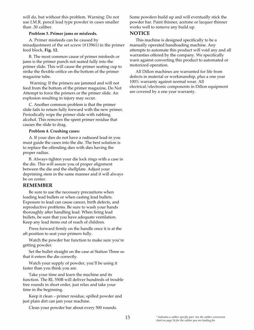
will do, but without this problem. Warning: Do notuse I.M.R. pencil lead type powder in cases smallerthan .30 caliber.
Problem 3. Primer jams or misfeeds.
A. Primer misfeeds can be caused bymisadjustment of the set screw (#13961) in the primerfeed block, Fig. 12.
B. The most common cause of primer misfeeds orjams is the primer punch not seated fully into theprimer slide. This will cause the primer seating cup tostrike the flexible orifice on the bottom of the primermagazine tube.
Warning: If the primers are jammed and will notfeed from the bottom of the primer magazine, Do NotAttempt to force the primers or the primer slide. Anexplosion resulting in injury may occur.
C. Another common problem is that the primerslide fails to return fully forward with the new primer.Periodically wipe the primer slide with rubbingalcohol. This removes the spent primer residue thatcauses the slide to drag.
Problem 4. Crushing cases:
A. If your dies do not have a radiused lead-in youmust guide the cases into the die. The best solution isto replace the offending dies with dies having theproper radius.
B. Always tighten your die lock rings with a case inthe die. This will assure you of proper alignmentbetween the die and the shellplate. Adjust yourdepriming stem in the same manner and it will alwaysbe on center.
REMEMBERBe sure to use the necessary precautions when
loading lead bullets or when casting lead bullets.Exposure to lead can cause cancer, birth defects, andreproductive problems. Be sure to wash your handsthoroughly after handling lead. When firing leadbullets, be sure that you have adequate ventilation.Keep any lead items out of reach of children.
Press forward firmly on the handle once it is at theaft position to seat your primers fully.
Watch the powder bar function to make sure you’regetting powder.
Set the bullet straight on the case at Station Three sothat it enters the die correctly.
Watch your supply of powder, you’ll be using itfaster than you think you are.
Take your time and learn the machine and itsfunction. The RL 550B will deliver hundreds of troublefree rounds in short order, just relax and take yourtime in the beginning.
Keep it clean – primer residue, spilled powder andjust plain dirt can jam your machine.
Clean your powder bar about every 500 rounds.
Some powders build up and will eventually stick thepowder bar. Paint thinner, acetone or lacquer thinnerworks well to remove any build up.
NOTICEThis machine is designed specifically to be a
manually operated handloading machine. Anyattempts to automate this product will void any and allwarranties offered by the company. We specificallywarn against converting this product to automated ormotorized operation.
All Dillon machines are warranted for life fromdefects in material or workmanship, plus a one year100% warranty against normal wear. Allelectrical/electronic components in Dillon equipmentare covered by a one year warranty.
* Indicates a caliber specific part. See the caliber conversionchart on page 16 for the caliber you are loading for.

16
Conversion Powder Shellplate Locator Handgun Calibers Kit Funnel Button.30 Luger #20175 C - #13564 5 - #13743 3.30 Mauser #20174 C - #13564 5 - #13743 3.32 ACP - 7.65mm #20160 S - #12845 8 - #13135 8.32 S&W Long #20146 S - #12845 D - #13092 3.32 Short Colt #20160 S - #12845 8 - #13135 8.380 ACP #20133 F - #13806 3 - #13684 39x18 #21656 9 - #14980 5 - #13743 39mm Luger #20127 F - #13806 5 - #13743 39x25 Dillon/.357 Sig. #21526 F - #13806 5 - #13743 2.38 S&W #20159 F - #13806 U - #12944 2.38 AMU #20278 F - #13806 O - #12013 3.38 Super #20127 F - #13806 5 - #13743 3.38 Sp.-.357 Mag./Max. #20132 D - #13599 2 - #13751 210mm/.40 S&W #20179 W - #13600 5 - #13743 2.41 AE #20277 AE - #13180 5 - #13743 3.41 Mag. #20135 H - #13240 6 - #13120 1.44 Sp. - Mag. #20136 G - #13427 4 - #13610 4.45 ACP #20126 E - #13782 1 - #13692 1.45 Auto Rim #20158 E - #13782 H - #13010 4.45 Colt #20137 E - #13782 C - #13334 4.45 Win. Mag. #20221 E - #13782 L - #12703 1.454 Casull #20137 E - #13782 C - #13334 4.50 AE #21428 50AE - #14465 50 - #13147 4Rifle Calibers.17 Rem. #20203 O - #12921 3 - #13684 3.218 Bee #20151 A - #13426 O - #12013 3.219 Zipper/Donaldson #20180 A - #13426 7 - #12501 4.220 Swift #20154 A - #13426 L - #12703 1.221 Rem. Fire Ball #20128 A - #13426 3 - #13684 3.222 Rem. - Rem. Mag. #20128 A - #13426 3 - #13684 3.22-250 #20145 A - #13426 1 - #13692 1.223 - 5.56 mm #20128 A - #13426 3 - #13684 3.224 Wby. Mag. #20235 A - #13426 A - #13211 2.225 Win. #20181 A - #13426 L - #12703 1.22 Hornet - K Hornet #20150 A - #13426 E - #12957 8.22 Rem. Jet #20165 A - #13426 2 - #13751 2.22 Savage Hi Power #20180 A - #13426 7 - #12501 4.240 Wby. Mag. #20192 I - #13305 1 - #13692 1.243 Win. #20192 I - #13305 1 - #13692 1.250 Savage-.250/3000 #20147 K - #13216 1 - #13692 1.25-06 #20147 K - #13216 1 - #13692 1.25-20 Win. #20176 543R - #13243 O - #12013 3.25-35 Win. #20197 K - #13216 7 - #12501 4.256 Win. Mag. #20215 543R - #13243 2 - #13751 2.257 Ack. Imp #20147 K - #13216 1 - #13692 1.257 Roberts #20147 K - #13216 1 - #13692 1.257 Wby. Mag. #20199 K - #13216 B - #13347 4.25 Rem. #20233 K - #13216 R - #13497 2.264 Win. Mag. #20210 Y - #12870 B - #13347 4.270 Wby. Mag. #20196 J - #13456 B - #13347 4.270 Win. #20142 J - #13456 1 - #13692 1.284 Win. #20142 J - #13456 1 - #13692 1.30 M1 Carbine #20131 C - #13564 8 - #13135 8.300 Win. Mag. #20188 B - #13587 B - #13347 4.30-06 #20138 B - #13587 1 - #13692 1.300 H&H Mag. #20188 B - #13587 B - #13347 4.300 Savage #20190 B - #13587 1 - #13692 1.300 Wby. Mag. #20188 B - #13587 B - #13347 4.303 British #20183 B - #13587 4 - #13610 4.30-30 Win. #20139 B - #13587 7 - #12501 4.30-338 Win. Mag. #20188 B - #13587 B - #13347 4
Conversion Powder Shellplate Locator Rifle Calibers cont... Kit Funnel Button.30-40 Krag #20185 B - #13587 P - #13134 4.307 Win. #20237 B - #13587 L - #12703 1.308 - 7.62 Nato #20130 B - #13587 1 - #13692 1.308 Norma Mag. #20188 B - #13587 B - #13347 4.30 Herret #20214 AK - #13015 7 - #12501 4.30 Merrill #20231 AK - #13015 L - #12703 1.30 Rem. -32 Rem. #20184 B - #13587 R - #13497 2.32-20 Win. #20177 S - #12845 O - #12013 3.32-40 Win. #20139 B - #13587 7 - #12501 4.32 H&R Mag. #20146 S - #12845 D - #13092 3.32 Win. Sp. #20139 B - #13587 7 - #12501 4.33 Win. #20202 Q - #13406 G - #13313 7.338 Win. Mag. #20156 Q - #13406 B - #13347 4.340 Wby. Mag. #20156 Q - #13406 B - #13347 4.348 Win. #20217 P - #13187 T - #12808 7.350 Rem. Mag. #20167 P - #13187 B - #13347 4.356 Win. #20238 P - #13187 L - #12703 1.357 Herrett #20172 D - #13599 7 - #12501 4.358 Win. #20170 P - #13187 1 - #13692 1.358 Norma Mag. #20167 P - #13187 B - #13347 4.35 Rem. #20166 P - #13187 M - #13230 2.35 Whelen #20170 P - #13187 1 - #13692 1.35 Win. #20168 P - #13187 P - #13134 4.375 H&H/Wby Mag. #20204 544R - #13531 B - #13347 4.375 Super Mag. #20226 543V - #13344 7 - #12501 4.378 Wby. Mag. #21665 544378 - #15010 G - #13313 7.38-40 Win. #20178 W - #13600 N - #10004 4.38-55 Win. Ballard #20226 543V - #13344 7 - #12501 4.444 Marlin #20164 543X - #12920 N - #10004 4.44-40 Win. #20206 G - #13427 N - #10004 4.45-70 Gov’t #20143 543T - #13407 G - #13313 7.416 Rem. Mag. #20771 544RM - #13415 B - #13347 4.455 Webley #20137 E - #13782 C - #13334 4.458 Win. Mag. #20161 543T - #13407 B - #13347 4.460 Wby. Mag. #21664 544460 - #15009 G - #13313 76.5-06 #20207 Y - #12870 1 - #13692 16.5 x 52 Carcano #20208 Y - #12870 M - #13230 26.5 mm x 54 Mann-Scho #20208 Y - #12870 M - #13230 26.5 x 55 Swed Mauser #20207 Y - #12870 1 - #13692 16.5 Japanese Arisaka #20209 Y - #12870 L - #12703 16.5mm Rem. Mag. #20210 Y - #12870 B - #13347 46mm Rem.- .244 #20192 I - #13305 1 - #13692 17mm-08 Rem. #20142 J - #13456 1 - #13692 17.62 x 39 Russian #20213 AK - #13015 A - #13211 27.62 x 54 Russian #20346 B - #13587 G - #13313 77x 57 Mauser #20142 J - #13456 1 - #13692 17 x 64 Brenneke #20142 J - #13456 1 - #13692 17.7 Japanese Arisaka #20130 B - #13587 1 - #13692 17mm BR #20216 N - #13014 1 - #13692 17mm Ex - 280 Rem. #20142 J - #13456 1 - #13692 17mm Rem. Mag. #20140 J - #13456 B - #13347 47mm Merrill #20230 N - #13014 L - #12703 17mm Int’l Rimmed #20223 N - #13014 7 - #12501 47mm TCU #20141 N - #13014 3 - #13684 37mm Wby. Mag. #20196 J - #13456 B - #13347 47-30 Waters #20223 J - #13456 7 - #12501 47.5 x 55 Swiss #20130 B - #13587 1 - #13692 17.65 Bel-Arg #20130 B - #13587 1 - #13692 18mm Mauser #20201 M - #12963 1 - #13692 18mm Rem. Mag. #20155 M - #12963 B - #13347 4
RL 450 & RL 550B Caliber Conversion ChartKits include shellplate, locator buttons and flow thru powder funnel.

Shellplate 1 Locator Button 1Powder Funnel
.22-250 A - #13426
.30-06 B - #13587
.300 Savage AK - #13015
.308 - 7.62 Nato B - #135877.7 Japanese Arisaka B - #135877.5 x 55 Swiss B - #135877.65 Bel-Arg B - #13587.45 ACP E - #13782.240 Wby. Mag. I - #13305.243 Win. I - #133056mm Rem.- .244 I - #13305.270 Win. J - #13456.284 Win. J - #134567mm-08 Rem. J - #134567x 57 Mauser J - #134567 x 64 Brenneke J - #134567mm Ex - 280 Rem. J - #13456.250 Savage-.250/3000 K - #13216.25-06 K - #13216.257 Ack. Imp K - #13216.257 Roberts K - #132168mm Mauser M - #129637mm BR N - #130147mm Int’l N - #13014.358 Win. P - #13187.35 Whelen P - #131876.5-06 Y - #128706.5 x 55 Swed Mauser Y - #12870
Shellplate 2 Locator Button 2.256 Win. Mag. 543R - #13243.22 Rem. Jet A - #13426.38 Sp.-.357 Mag./Max. D - #13599
Shellplate 3 Locator Button 3.221 Rem. Fire Ball A - #13426.222 Rem. - Rem. Mag. A - #13426.223 - 5.56 mm A - #13426.380 ACP F - #138067mm TCU N - #13014.17 Rem. O - #12921
Shellplate 4 Locator Button 4.303 British B - #13587.44 Sp. - Mag. G - #13427
Shellplate 5 Locator Button 29x25 Dillon/.357 Sig. F - #1380610mm/.40 S&W W - #13600
Shellplate 5 Locator Button 39x18 9 - #14980.41 AE AE - #13180.30 Luger C - #13564.30 Mauser C - #135649mm Luger F - #13806.38 Super F - #13806
Shellplate 6 Locator Button 1.41 Mag. H - #13240
Shellplate 7 Locator Button 4Powder Funnel
.375 Super Mag. 543V - #13344
.38-55 Win. Ballard 543V - #13344
.219 Zipper A - #13426
.219 Donaldson A - #13426
.22 Savage Hi Power A - #13426
.30 Herret AK - #13015
.30-30 Win. B - #13587
.32-40 Win. B - #13587
.32 Win. Sp. B - #13587
.357 Herrett D - #135997-30 Waters N - #13014.25-35 Win. K - #132167mm Int’l Rimmed N - #13014
Shellplate 8 Locator Button 8.30 M1 Carbine C - #13564.32 ACP - 7.65mm S - #12845.32 Short Colt S - #12845
Shellplate 50 Locator Button 4.50 AE 50AE - #14465
Shellplate A Locator Button 2.224 Wby. Mag. A - #134267.62 x 39 Russian AK - #13015
Shellplate B Locator Button 4.458 Win. Mag. 543T - #13407.375 H&H 544R - #13531.375 Wby Mag. 544R - #13531.416 Rem. Mag. 544RM - #13415.300 Win. Mag. B - #13587.300 H&H Mag. B - #13587.300 Wby. Mag. B - #13587.30-338 Win. Mag. B - #13587.308 Norma Mag. B - #13587.270 Wby. Mag. J - #134567mm Rem. Mag. J - #134567mm Wby. Mag. J - #13456.257 Wby. Mag. K - #132168mm Rem. Mag. M - #12963.350 Rem. Mag. P - #13187.358 Norma Mag. P - #13187.338 Win. Mag. Q - #13406.340 Wby. Mag. Q - #13406.264 Win. Mag. Y - #128706.5mm Rem. Mag. Y - #12870
Shellplate C Locator Button 4.45 Colt E - #13782.454 Casull E - #13782.455 Webley E - #13782
Shellplate D Locator Button 3.32 S&W Long S - #12845.32 H&R Mag. S - #12845
Shellplate E Locator Button 8.22 Hornet - K Hornet A - #13426
Shellplate G Locator Button 7Powder Funnel
.45-70 Gov’t 543T - #13407
.378 Wby. Mag. 544378 - #150107.62 x 54 Russian B - #13587.33 Win. Q - #13406.460 Wby. Mag. 544460 - #15009
Shellplate H Locator Button 4.45 Auto Rim E - #13782
Shellplate L Locator Button 1 .220 Swift A - #13426.225 Win. A - #13426.30 Merrill AK - #13015.307 Win. B - #13587.45 Win. Mag. E - #137827mm Merrill N - #13014.356 Win. P - #131876.5 Japanese Arisaka Y - #12870
Shellplate M Locator Button 2.35 Rem. P - #131876.5 x 52 Carcano Y - #128706.5 mm x 54 Mann-Scho Y - #12870
Shellplate N Locator Button 4.444 Marlin 543X - #12920.44-40 Win. G - #13427.38-40 Win. W - #13600
Shellplate O Locator Button 3.25-20 Win. 543R - #13243.218 Bee A - #13426.38 AMU F - #13806.32-20 Win. S - #12845
Shellplate P Locator Button 4.30-40 Krag B - #13587.35 Win. P - #13187
Shellplate R Locator Button 2.30 Rem. -32 Rem. B - #13587.25 Rem. K - #13216
Shellplate T Locator Button 7.348 Win. P - #13187
Shellplate U Locator Button 2.38 S&W F - #13806
RL 450 & RL 550B Caliber Cross Reference Chart
17

Dillon Precision Products, Inc.8009 E. Dillon’s WayScottsdale, AZ 85260
(480) 948-8009FAX (480) 998-2786
Web Site: www.dillonprecision.comE-mail: [email protected]
Technical Support & Customer Service(800) 223-4570
On the cover…The RL 550B is pictured with optional accessories:Strong Mount #22051Aluminum Roller Handle #17950Low Powder Sensor #16306Bullet Tray #22214Other accessories available for the RL 550B include:Video Instruction Manual #14621Machine Cover #13795Maintenance Kit & Spare Parts Kit #97016The Blue Press, Dillon’s monthly catalog, has a complete listing of accessories available for all machines.