Embed Size (px)
Citation preview
Atlas CopcoRefrigerant air dryers FX 1-21 (7-1236 l/s, 14-2516 cfm)
�
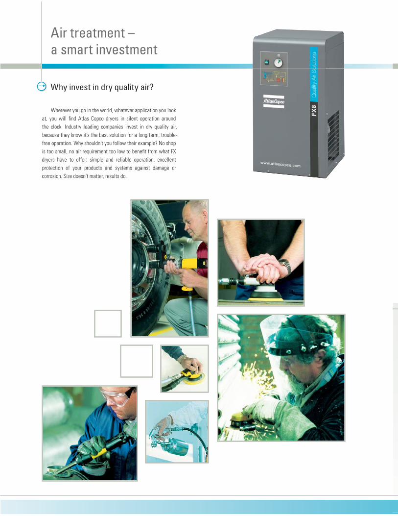
Wherever you go in the world, whatever application you look
at, you will find Atlas Copco dryers in silent operation around
the clock. Industry leading companies invest in dry quality air,
because they know it’s the best solution for a long term, trouble-
free operation. Why shouldn’t you follow their example? No shop
is too small, no air requirement too low to benefit from what FX
dryers have to offer: simple and reliable operation, excellent
protection of your products and systems against damage or
corrosion. Size doesn’t matter, results do.
Why invest in dry quality air?
Air treatment – a smart investment
� �
�
� �
� �
�
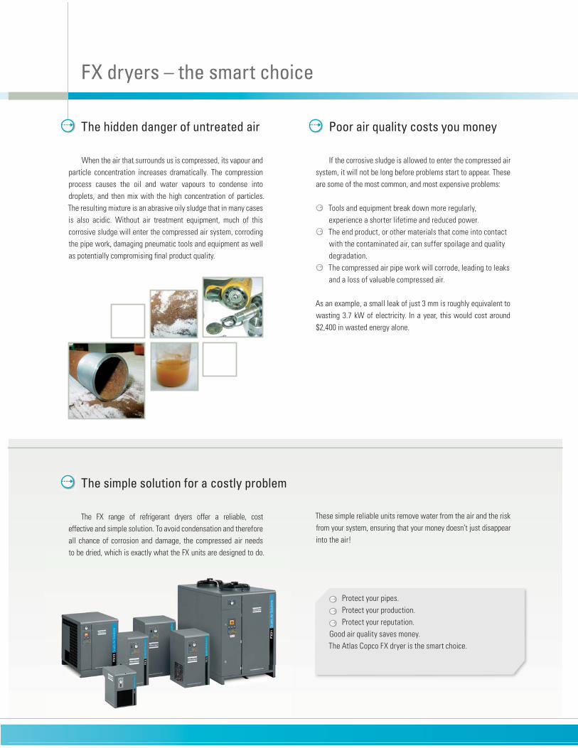
When the air that surrounds us is compressed, its vapour and
particle concentration increases dramatically. The compression
process causes the oil and water vapours to condense into
droplets, and then mix with the high concentration of particles.
The resulting mixture is an abrasive oily sludge that in many cases
is also acidic. Without air treatment equipment, much of this
corrosive sludge will enter the compressed air system, corroding
the pipe work, damaging pneumatic tools and equipment as well
as potentially compromising final product quality.
The hidden danger of untreated air
� Protect your pipes.
� Protect your production.
� Protect your reputation.
Good air quality saves money.
The Atlas Copco FX dryer is the smart choice.
FX dryers – the smart choice
Poor air quality costs you money
If the corrosive sludge is allowed to enter the compressed air
system, it will not be long before problems start to appear. These
are some of the most common, and most expensive problems:
� Tools and equipment break down more regularly,
experience a shorter lifetime and reduced power.
� The end product, or other materials that come into contact
with the contaminated air, can suffer spoilage and quality
degradation.
� The compressed air pipe work will corrode, leading to leaks
and a loss of valuable compressed air.
As an example, a small leak of just 3 mm is roughly equivalent to
wasting 3.7 kW of electricity. In a year, this would cost around
$2,400 in wasted energy alone.
The simple solution for a costly problem
The FX range of refrigerant dryers offer a reliable, cost
effective and simple solution. To avoid condensation and therefore
all chance of corrosion and damage, the compressed air needs
to be dried, which is exactly what the FX units are designed to do.
These simple reliable units remove water from the air and the risk
from your system, ensuring that your money doesn’t just disappear
into the air!

�
�
�������������������
�������������������
1 2
3
FX refrigerant dryers
Solid performance� �Steady pressure dew point
� �No freezing of condensed moisture
� �No chance of moisture entering the compressed air system.
Simple reliability� �Quality components, generously sized
� �Simple and proven design
� �Effective control system (hot gas bypass).
Easy installation� �Plug and play concept
� �Single electrical connection
� �All units pre-commissioned
� �Self regulating.
Minimal maintenance� �Long service intervals
� �Few component replacements
� �Ergonomic design for fast access to key components.
Significant cost savings� �Increased reliability and lifetime of tools and equipment
� �Reduced pipe work leaks, meaning reduced energy bill
� �Fewer repairs to tools, machines and pipe work
� �Less inconvenient breakdowns and stoppages
� �Minimal chance of product spoilage through
moisture carryover.
The benefits add up
Adding filtration to the installation will further increase the
quality of the air, resulting in even less chance that tools and ma-
chines will be damaged and final product quality compromised.
1 The prefilter will protect the dryer, and also remove free water, particles to 1 micron and oil to 0.1 mg/m3.
2 The final filter removes particles to 0.01 micron and oil to 0.01mg/m3.
3 The final result is dry clean air, which allows you to concentrate on your business, without problems.
No installation is complete without filtration
��
1
2
3
4
5 6 7
89
1112
13
14
10
15
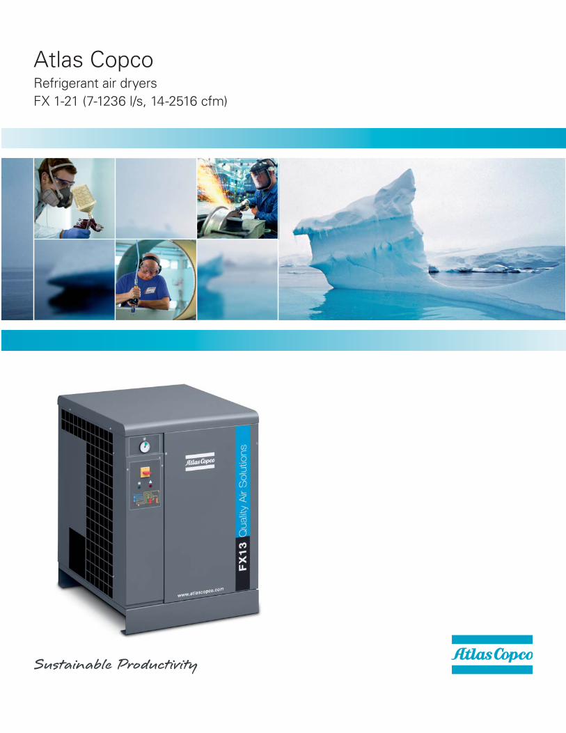
FX refrigerant dryersIndustrial performance – simple reliability
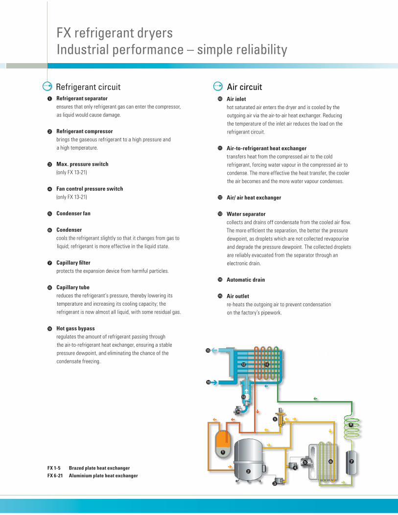
1 Refrigerant separator ensures that only refrigerant gas can enter the compressor,
as liquid would cause damage.
2 Refrigerant compressor brings the gaseous refrigerant to a high pressure and
a high temperature.
3 Max. pressure switch (only FX 13-21)
4 Fan control pressure switch (only FX 13-21)
5 Condenser fan
6 Condenser cools the refrigerant slightly so that it changes from gas to
liquid; refrigerant is more effective in the liquid state.
7 Capillary filter protects the expansion device from harmful particles.
8 Capillary tube reduces the refrigerant’s pressure, thereby lowering its
temperature and increasing its cooling capacity; the
refrigerant is now almost all liquid, with some residual gas.
9 Hot gass bypass regulates the amount of refrigerant passing through
the air-to-refrigerant heat exchanger, ensuring a stable
pressure dewpoint, and eliminating the chance of the
condensate freezing.
Refrigerant circuit10 Air inlet hot saturated air enters the dryer and is cooled by the
outgoing air via the air-to-air heat exchanger. Reducing
the temperature of the inlet air reduces the load on the
refrigerant circuit.
11 Air-to-refrigerant heat exchanger transfers heat from the compressed air to the cold
refrigerant, forcing water vapour in the compressed air to
condense. The more effective the heat transfer, the cooler
the air becomes and the more water vapour condenses.
12 Air/ air heat exchanger
13 Water separator collects and drains off condensate from the cooled air flow.
The more efficient the separation, the better the pressure
dewpoint, as droplets which are not collected revapourise
and degrade the pressure dewpoint. The collected droplets
are reliably evacuated from the separator through an
electronic drain.
14 Automatic drain
15 Air outlet re-heats the outgoing air to prevent condensation
on the factory’s pipework.
Air circuit
FX 1-5 Brazed plate heat exchangerFX 6-21 Aluminium plate heat exchanger
Air circuit
�
�
Technical data 50 Hz
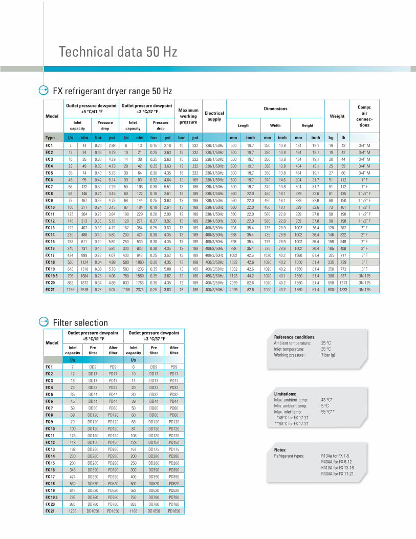
FX refrigerant dryer range 50 Hz
Model
Outlet pressure dewpoint +5 °C/41 °F
Outlet pressure dewpoint +3 °C/37 °F
Inletcapacity
Prefilter
Afterfilter
Inletcapacity
Prefilter
Afterfilter
l/s l/s
FX 1 7 DD9 PD9 6 DD9 PD9
FX 2 12 DD17 PD17 10 DD17 PD17
FX 3 16 DD17 PD17 14 DD17 PD17
FX 4 23 DD32 PD32 20 DD32 PD32
FX 5 35 DD44 PD44 30 DD32 PD32
FX 6 45 DD44 PD44 39 DD44 PD44
FX 7 58 DD60 PD60 50 DD60 PD60
FX 8 69 DD120 PD120 60 DD60 PD60
FX 9 79 DD120 PD120 68 DD120 PD120
FX 10 100 DD120 PD120 87 DD120 PD120
FX 11 125 DD120 PD120 108 DD120 PD120
FX 12 148 DD150 PD150 128 DD150 PD150
FX 13 192 DD280 PD280 167 DD175 PD175
FX 14 230 DD280 PD280 200 DD280 PD280
FX 15 288 DD280 PD280 250 DD280 PD280
FX 16 345 DD390 PD390 300 DD390 PD390
FX 17 424 DD390 PD390 400 DD390 PD390
FX 18 530 DD520 PD520 500 DD520 PD520
FX 19 618 DD520 PD520 583 DD520 PD520
FX 19.5 795 DD780 PD780 750 DD780 PD780
FX 20 883 DD780 PD780 833 DD780 PD780
FX 21 1236 DD1050 PD1050 1166 DD1050 PD1050
Filter selection
Notes:Refrigerant types: R134a for FX 1-5
R404A for FX 6-12
R410A for FX 13-16
R404A for FX 17-21
Limitations:Max. ambient temp: 43 °C*
Min. ambient temp: 5 °C
Max. inlet temp: 55 °C**
*46°C for FX 17-21
**60°C for FX 17-21
Reference conditions:Ambient temperature: 25 °C
Inlet temperature: 35 °C
Working pressure: 7 bar (g)
Model
Outlet pressure dewpoint +5 °C/41 °F
Outlet pressure dewpoint +3 °C/37 °F Maximum
working pressure
Electricalsupply
Dimensions
Weight
Compr. air
connec-tions
Inlet
capacity
Pressure
drop
Inlet
capacity
Pressure
dropLength Width Height
Type l/s cfm bar psi l/s cfm bar psi bar psi mm inch mm inch mm inch kg lb
FX 1 7 14 0.20 2.88 6 13 0.15 2.18 16 232 230/1/50Hz 500 19.7 350 13.8 484 19.1 19 42 3/4” M
FX 2 12 24 0.33 4.79 10 21 0.25 3.63 16 232 230/1/50Hz 500 19.7 350 13.8 484 19.1 19 42 3/4” M
FX 3 16 35 0.33 4.79 14 30 0.25 3.63 16 232 230/1/50Hz 500 19.7 350 13.8 484 19.1 20 44 3/4” M
FX 4 23 49 0.33 4.79 20 42 0.25 3.63 16 232 230/1/50Hz 500 19.7 350 13.8 484 19.1 25 55 3/4” M
FX 5 35 74 0.40 5.75 30 64 0.30 4.35 16 232 230/1/50Hz 500 19.7 350 13.8 484 19.1 27 60 3/4” M
FX 6 45 95 0.42 6.14 39 83 0.32 4.64 13 189 230/1/50Hz 500 19.7 370 14.6 804 31.7 51 112 1” F
FX 7 58 122 0.50 7.29 50 106 0.38 5.51 13 189 230/1/50Hz 500 19.7 370 14.6 804 31.7 51 112 1” F
FX 8 69 146 0.24 3.45 60 127 0.18 2.61 13 189 230/1/50Hz 560 22.0 460 18.1 829 32.6 61 135 1 1/2” F
FX 9 79 167 0.33 4.79 68 144 0.25 3.63 13 189 230/1/50Hz 560 22.0 460 18.1 829 32.6 68 150 1 1/2” F
FX 10 100 211 0.24 3.45 87 184 0.18 2.61 13 189 230/1/50Hz 560 22.0 460 18.1 829 32.6 73 161 1 1/2” F
FX 11 125 264 0.26 3.84 108 229 0.20 2.90 13 189 230/1/50Hz 560 22.0 580 22.8 939 37.0 90 198 1 1/2” F
FX 12 148 313 0.36 5.18 128 271 0.27 3.92 13 189 230/1/50Hz 560 22.0 580 22.8 939 37.0 90 198 1 1/2” F
FX 13 192 407 0.33 4.79 167 354 0.25 3.63 13 189 400/3/50Hz 898 35.4 735 28.9 1002 36.4 128 282 2” F
FX 14 230 488 0.40 5.80 200 424 0.30 4.35 13 189 400/3/50Hz 898 35.4 735 28.9 1002 36.4 146 322 2” F
FX 15 288 611 0.40 5.80 250 530 0.30 4.35 13 189 400/3/50Hz 898 35.4 735 28.9 1002 36.4 158 348 2” F
FX 16 345 731 0.40 5.80 300 636 0.30 4.35 13 189 400/3/50Hz 898 35.4 735 28.9 1002 36.4 185 408 2” F
FX 17 424 899 0.28 4.07 400 848 0.25 3.63 13 189 400/3/50Hz 1082 42.6 1020 40.2 1560 61.4 325 717 3" F
FX 18 530 1124 0.34 4.89 500 1060 0.30 4.35 13 189 400/3/50Hz 1082 42.6 1020 40.2 1560 61.4 335 739 3" F
FX 19 618 1310 0.39 5.70 583 1236 0.35 5.08 13 189 400/3/50Hz 1082 42.6 1020 40.2 1560 61.4 350 772 3" F
FX 19.5 795 1684 0.28 4.06 750 1589 0.25 3.62 13 189 460/3/60Hz 1123 44.2 1020 40.1 1560 61.4 380 837 DN 125
FX 20 883 1872 0.34 4.89 833 1766 0.30 4.35 13 189 400/3/50Hz 2099 82.6 1020 40.2 1560 61.4 550 1213 DN 125
FX 21 1236 2516 0.28 4.07 1166 2374 0.25 3.63 13 189 400/3/50Hz 2099 82.6 1020 40.2 1560 61.4 600 1323 DN 125
�
�
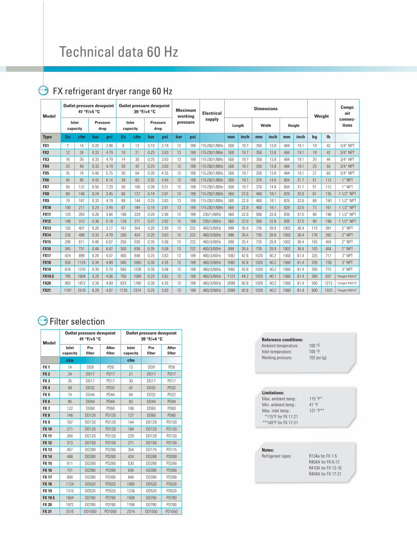
Technical data 60 Hz
FX refrigerant dryer range 60 Hz
Filter selection
Limitations:Max. ambient temp.: 115 °F*
Min. ambient temp.: 41 °F
Max. inlet temp.: 131 °F**
*115°F for FX 17-21
**140°F for FX 17-21
Reference conditions:Ambient temperature: 100 °F
Inlet temperature: 100 °F
Working pressure: 102 psi (g)
Notes:Refrigerant types: R134a for FX 1-5
R404A for FX 6-12
R410A for FX 13-16
R404A for FX 17-21
Model
Outlet pressure dewpoint 41 °F/+5 °C
Outlet pressure dewpoint 39 °F/+4 °C Maximum
working pressure
Electricalsupply
Dimensions
Weight
Compr. air
connec-tions
Inlet
capacity
Pressure
drop
Inlet
capacity
Pressure
dropLength Width Height
Type l/s cfm bar psi l/s cfm bar psi bar psi mm inch mm inch mm inch kg lb
FX1 7 14 0.20 2.88 6 13 0.15 2.18 13 189 115-230/1/60Hz 500 19.7 350 13.8 484 19.1 19 42 3/4” NPT
FX2 12 24 0.33 4.79 10 21 0.25 3.63 13 189 115-230/1/60Hz 500 19.7 350 13.8 484 19.1 19 42 3/4” NPT
FX3 16 35 0.33 4.79 14 30 0.25 3.63 13 189 115-230/1/60Hz 500 19.7 350 13.8 484 19.1 20 44 3/4” NPT
FX4 23 49 0.33 4.79 20 42 0.25 3.63 13 189 115-230/1/60Hz 500 19.7 350 13.8 484 19.1 25 55 3/4” NPT
FX5 35 74 0.40 5.75 30 64 0.30 4.35 13 189 115-230/1/60Hz 500 19.7 350 13.8 484 19.1 27 60 3/4” NPT
FX6 45 95 0.42 6.14 39 83 0.32 4.64 13 189 115-230/1/60Hz 500 19.7 370 14.6 804 31.7 51 112 1” NPT
FX7 58 122 0.50 7.29 50 106 0.38 5.51 13 189 115-230/1/60Hz 500 19.7 370 14.6 804 31.7 51 112 1” NPT
FX8 69 146 0.24 3.45 60 127 0.18 2.61 13 189 115-230/1/60Hz 560 22.0 460 18.1 829 32.6 61 135 1 1/2” NPT
FX9 79 167 0.33 4.79 68 144 0.25 3.63 13 189 115-230/1/60Hz 560 22.0 460 18.1 829 32.6 68 150 1 1/2” NPT
FX10 100 211 0.24 3.45 87 184 0.18 2.61 13 189 115-230/1/60Hz 560 22.0 460 18.1 829 32.6 73 161 1 1/2” NPT
FX11 125 264 0.26 3.84 108 229 0.20 2.90 13 189 230/1/60Hz 560 22.0 580 22.8 939 37.0 90 198 1 1/2” NPT
FX12 148 313 0.36 5.18 128 271 0.27 3.92 13 189 230/1/60Hz 560 22.0 580 22.8 939 37.0 90 198 1 1/2” NPT
FX13 192 407 0.26 3.77 167 354 0.20 2.90 13 232 460/3/60Hz 898 35.4 735 28.9 1002 36.4 173 381 2” NPT
FX14 230 488 0.33 4.79 200 424 0.25 3.63 13 232 460/3/60Hz 898 35.4 735 28.9 1002 36.4 178 392 2” NPT
FX15 288 611 0.46 6.67 250 530 0.35 5.08 13 232 460/3/60Hz 898 35.4 735 28.9 1002 36.4 183 404 2” NPT
FX16 345 731 0.46 6.67 300 636 0.35 5.08 13 232 460/3/60Hz 898 35.4 735 28.9 1002 36.4 183 404 2” NPT
FX17 424 899 0.28 4.07 400 848 0.25 3.63 13 189 460/3/60Hz 1082 42.6 1020 40.2 1560 61.4 325 717 3" NPT
FX18 530 1124 0.34 4.89 500 1060 0.30 4.35 13 189 460/3/60Hz 1082 42.6 1020 40.2 1560 61.4 335 739 3" NPT
FX19 618 1310 0.39 5.70 583 1236 0.35 5.08 13 189 460/3/60Hz 1082 42.6 1020 40.2 1560 61.4 350 772 3" NPT
FX19.5 795 1684 0.28 4.06 750 1589 0.25 3.62 13 189 460/3/60Hz 1123 44.2 1020 40.1 1560 61.4 380 837 Flanged ANSI 6”
FX20 883 1872 0.34 4.89 833 1766 0.30 4.35 13 189 460/3/60Hz 2099 82.6 1020 40.2 1560 61.4 550 1213 Flanged ANSI 6”
FX21 1187 2516 0.28 4.07 1120 2374 0.25 3.63 13 189 460/3/60Hz 2099 82.6 1020 40.2 1560 61.4 600 1323 Flanged ANSI 6”
Model
Outlet pressure dewpoint41 °F/+5 °C
Outlet pressure dewpoint 39 °F/+4 °C
Inletcapacity
Prefilter
Afterfilter
Inletcapacity
Prefilter
Afterfilter
cfm cfm
FX 1 14 DD9 PD9 13 DD9 PD9
FX 2 24 DD17 PD17 21 DD17 PD17
FX 3 35 DD17 PD17 30 DD17 PD17
FX 4 49 DD32 PD32 42 DD32 PD32
FX 5 74 DD44 PD44 64 DD32 PD32
FX 6 95 DD44 PD44 83 DD44 PD44
FX 7 122 DD60 PD60 106 DD60 PD60
FX 8 146 DD120 PD120 127 DD60 PD60
FX 9 167 DD120 PD120 144 DD120 PD120
FX 10 211 DD120 PD120 184 DD120 PD120
FX 11 264 DD120 PD120 229 DD120 PD120
FX 12 313 DD150 PD150 271 DD150 PD150
FX 13 407 DD280 PD280 354 DD175 PD175
FX 14 488 DD280 PD280 424 DD280 PD280
FX 15 611 DD280 PD280 530 DD280 PD280
FX 16 731 DD390 PD390 636 DD390 PD390
FX 17 899 DD390 PD390 848 DD390 PD390
FX 18 1124 DD520 PD520 1060 DD520 PD520
FX 19 1310 DD520 PD520 1236 DD520 PD520
FX 19.5 1684 DD780 PD780 1589 DD780 PD780
FX 20 1872 DD780 PD780 1766 DD780 PD780
FX 21 2516 DD1050 PD1050 2374 DD1050 PD1050

Driven by innovation
With more than 135 years of innovation and experience, Atlas Copco delivers the products and
services to help maximize your company’s efficiency and productivity. As a global industry leader,
we are dedicated to offering high air quality at the lowest possible cost of ownership. Through
continuous advancements, we strive to safeguard your bottom line and bring you peace of mind.
Local interaction
Atlas Copco Compressors LLC is headquartered in Rock Hill, SC. Our 187,000 sq. ft. manufacturing
plant is one of several Atlas Copco production units across the U.S., including a custom design
facility in Houston, TX. We take the best possible care of our customers through four regional
customer centers and appointed authorized distributors, supported by a 131,000 sq. ft. distribution
center and a network of field based personnel throughout the country. Across all of our different
business types and brands, Atlas Copco employs approximately 3,300 people in the U.S.
Committed to sustainability
In 2010, Atlas Copco was named one of the Top 100 Sustainable Companies in the World for
the fifth consecutive year. Through our Water for All organization, Atlas Copco is committed to
supporting projects that supply clean water to those who need it most. Visit www.water4all.
org for more information. All Atlas Copco Compressors facilities in the United States are triple
certified to ISO 14001, ISO 9001 and OHSAS 18001; a set of standards to protect the environment,
ensure product quality, and promote our employees’ health and occupational safety.
© Copyright 2012 Atlas Copco Compressors LLC. All rights reserved.® Atlas Copco is a registered trademark of Atlas Copco AB
��������� ������������������������ ����������������������������� �� ���� ���������������-ing. Atlas Copco assumes no responsibility or liability related to the purchaser’s/user’s breathing system.
������������������������������������������������������������������ ��������������������������-tion or application purposes.
1310
905
7 30
FA
B 2
M 3
/12
www.atlascopco.us866-344-4887