Embed Size (px)
Citation preview

20/04/23 1
Product Training Notes
1300 Series Electronic Engine

20/04/23 2
Course Content
•HEUI fuel/Oil system function and operation
•ECM management system
•Fault finding using the MPSI
•Fault finding using PC software
•Service and maintenance

20/04/23 5
Shaping the Future
• Optimised performance characteristics
• Improved engine emissions
• Engine packaging
• New reliability and durability features
• Expanded options range
• New service solutions

20/04/23 6
Engine Performance
• Efficient combustion system
• Fully optimised power, torque and fuel curves for optimum performance
• No engine power loss due to high fuel temperatures
• Improved transient conditions
• Unaided cold start of -20ºC
• Stabilised idle
20/04/23 7
ENGINE IDENTIFICATION
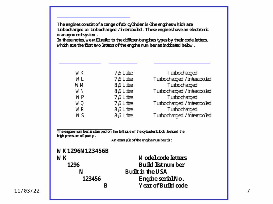
The engines consist of a range of six cylinder in-line engines which areturbocharged or turbocharged / intercooled. These engines have an electronicmanagement system.In these notes, we will refer to the different engines types by their code letters,which are the first two letters of the engine number as indicated below.
CODE LETTERS CAPACITY ASPIRATION SYSTEM
WK 7,6 Litre TurbochargedWL 7,6 Litre Turbocharged / intercooledWM 8,6 Litre TurbochargedWN 8,6 Litre Turbocharged / intercooledWP 7,6 Litre TurbochargedWQ 7,6 Litre Turbocharged / intercooledWR 8,6 Litre TurbochargedWS 8,6 Litre Turbocharged / intercooled
ENGINE NUMBERS The engine number is stamped on the left side of the cylinder block, behind thehigh pressure oil pump.
An example of the engine number is :
WK1296N123456BWK Model code letters
1296 Build list number N Built in the USA 123456 Engine serial No.
B Year of Build code

20/04/23 8
1300 Series Electronic Engine General Data Number of cylindrs……………………………………………………………………………6 Cylinder arrangement……………………………………………………………………In line Cycle……………………………………………………………………………….Four Stroke Introduction system……………………………...Turbocharged or Turbocharged /Intercooled Combulsion system…………………………………………………………….Direct injection Nominal bore: - WK & WL………………………………………………………………109, 2mm (4.301 in) - WM & WN……………………………………………………………...135, 9mm (5.350 in) stroke: - WK & WL……………………………………………………………….112,9mm (4.301 in) - WM & WN………………………………………………………………135,9mm (4.590 in) compression ratio………………………………………………………………………...16.5:1 Cubic capacity: -WK & WL…………………………………………………………….7,64 litres (466.4 cu in) - WM & WN…………………………………………………………...8,71 litres (531.0 cu in) Firing order…………………………………………………………………………..1,5,3,6,2,4 Valve tip clearances (cold): - Inlet & exhaust…………………………………………………………….0,64mm (0.025 in) Lubricating oil pressure (minimum): - Idle……………………………………………………………………..104 kpa (15 1bf sq in) - Maximum no load engine speed & normal temp……………………...276 kpa (40 1bf sq in) Lubricating oil capacity : Sump………………………………………………………………..22,7 litres (40.0 UK pints) Filter…………………………………………………………………...5,6 litres (9.9 UK pints) Direction of rotation………………………………………………….Clockwise from the front Valve seat angle: - Inlet………………………………………………………………………………..30 Degrees - Exhaust……………………………………………………………………………45 Degrees
20/04/23 9
SYSTEM OPERATIONEngine oil is drawn from the sump by the engine oil pump and flows through the oil cooler andfilter to the high pressure supply pump. The supply pump pressurizes the oil to between 450and 3,000 psi. Pump outlet pressure is determined by the injection pressure regulator valve(IPR) which dumps excess oil to drain. The pressure maintained by the IPR is determined by avariable electrical signal supplied by the Electronic Control Module (ECM).
High pressure oil is supplied to a pressure rail attached to the cylinder head, and by drillings inthe head is available to all injectors. The energised solenoid lifts the injector poppet valve offits seat. Heat pressure oil from the rail then enters the injector causing injection to occur.
Injection ends when the ECM switches off the current to the solenoid. The poppet spring thencauses the poppet to close. As the poppet closes, the high pressure supply oil from the rail isblocked and the intensifier piston cavity is connected to drain through the armature cavity.
The plunger return spring then pushes the intensifier and plunger back to their originalposition. The upward movement of the plunger lifts the fill check valve off its seat and drawsfuel into the plunge cavity for the next stroke.
Fuel is drawn from the fuel tank by a mechanical fuel pump and flows through a filter to thepressure rail attached to the cylinder head, via drillings in the head to the injectors. Excess fuelflows back to the tank via a spring loaded valve, which maintains a positive fuel pressure in thepressure rail.

20/04/23 10
ydraulically Actuated
Lectronically controlled
nit
njector
FUEL SYSTEM

20/04/23 11
Engine Emissions
• Compliant to EPA and EC Stage 1 emissions legislation
• Excellent platform for stage 2 emissions legislation and beyond
• No visible smoke
• Up to 3.5 dBA quieter, which equates to over a 50%
improvement in perceived noise

20/04/23 12
The 1300 series electronic engine uses injector units,which are hydraulically actuated and electronically controlled. This offers vastly improved performance over mechanical systems by controlling the following areas:
•Rate ControlThe rate of injection can be controlled to meet any engine condition, due to theinjector being hydraulically actuated rather than mechanically.The rate of injection and injection pressure does not depend on engine speed.
•Timing ControlBoth start and end of injection is electronically controlled, unlike conventionalelectronically controlled mechanically actuated unit injectors, the plunger does not move until the solenoid is energised.This means that plunger movement is not limited to the speed or duration of a cam lobe.
FUEL SYSTEM

20/04/23 13
Injector UnitElectronicSolenoid
Poppet Valve
IntensifierPiston
CheckValve
NozzleAssembly
The injector uses the hydraulic energy of the pressurised oil to cause injection.The pressure of the incoming oil controls the speed of the intensifier piston and therefore, the rate of injection. The amountof fuel injected is determined by the duration of the pulse from the ECM and how long it keeps the solenoid energised. As long as the solenoid is energised and the poppet valve is off its seat, oil continues to push down the intensifier and plunger until the intensifier reaches the bottom of its bore.
FUEL SYSTEM

20/04/23 14
Injector Unit Top Section
Wire to ECMPoppet
SolenoidArmature
FUEL SYSTEM

20/04/23 15
Injector Unit Mid Section
Fuel Port
Oil Feed Port
Oil Outlet Port
Plunger Spill Port
An intensifier piston in the injectorunit multiplies hydraulic force on the plunger.By varying the hydraulic inputpressure, injection pressure can be controlled in a range from 3,000 to 21,000 psi.
FUEL SYSTEM

20/04/23 16
Injector Unit Bottom Section
Needle
Nozzle Assembly
Spill Port closed during injection
FUEL SYSTEM

20/04/23 17
Injector Unit Bottom Section
Each injection is made up of two stages.
• Pilot Injection• Main Injection
Injection Pressure can be as highas 21,000 Psi.
FUEL SYSTEM

20/04/23 18
Injector Pilot Injection
Pilot Injection
Main Injection
Delay Period
FUEL SYSTEM

20/04/23 19
FUEL SYSTEM
Lift Pump
HEUI Injectors
Fuel Filter
Fuel Tank

20/04/23 20
Fuel specification
Cetane number. 50 minimumViscosity 2.0/4.5 centistokes at 400CDensity 0,835/0,855 kg/litreSulphur 0.2% of mass, maximumDistillation 85% at 3500C

20/04/23 21
OIL SYSTEM
Oil Sump
HEUI Injectors
High Pressure Oil Rail
Oil Cooler and Filter
To Engine Lubrication System
Engine Oil Pump
High Pressure Oil Supply Pump
(Rexroth pump)

20/04/23 22
Oil specification
When available
API CG-4, API CH-4 or ACEA E3
When NOT available
API CF-4 or ACEA E2
20/04/23 23
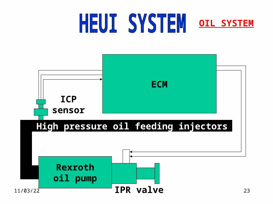
OIL SYSTEM
Rexrothoil pump
IPR valve
ECM
High pressure oil feeding injectors
ICPsensor

20/04/23 24
ECM management system

20/04/23 25
Engine Sensors
Injection Control
Pressure
Camshaft Position
Boost Pressure
Oil Temperature
Oil Pressure
Coolant Temperature
Engine Speed

20/04/23 26
Cam position sensor
• 24 vanes
• 1 narrow vain
• Sends engine speed• to ECM
• Sends engine position to ECM
NarrowVain
C.P.S

20/04/23 27
Cam position sensor
Narrow vain
Volts
5
6
0
1
2
3
4
Degrees
Hall effect

20/04/23 28
Electronic ControlModule
ECM
HEUI Injectors Sensors
Stop / Start Switch

20/04/23 29
Temperature sensors
Thermistor sensors
• Oil temp
• Coolant temp
• Air temp

20/04/23 30
Coolant specification
The quality of the coolant which is used can have a great effect on the efficiency and life of thecooling system. The recommendations indicated below can help to maintain a good coolingsystem and to protect it against frost and/or corrosion.
If the correct procedures are not used, Perkins cannot be held responsible for frost or corrosion
damage. 1 If it is possible, use clean soft water in the coolant.2 If an antifreeze mixture, other than Perkins POWERPART, is used to prevent frost damage, itmust have an ethanediol base (ethylene glycol) with a corrosion inhibitor. It is recommended thatthe corrosion inhibitor is of the sodium nitrite/sodium molybdate type. The antifreeze mixturemust be an efficient coolant at all ambient temperatures and it must provide protection againstcorrosion. It must also have a specification at least as good as the requirements of either BS6580or MOD AL39. Perkins POWERPART antifreeze exceeds the requirements of the abovestandard.
The quality of the antifreeze coolant must be checked at least once a year, for example, at thebeginning of the cold period. The coolant must be renewed every two years.
The antifreeze mixture must consist of equal quantities of antifreeze and water. Concentrations ofmore than 50% of antifreeze must not be used because these can affect adversely the performanceof the coolant.
3 When frost protection is not necessary, it is still an advantage to use an approved antifreezemixture because this gives a protection against corrosion and also raises the boiling point of thecoolant. If an approved antifreeze mixture is not available, add a correct mixture of corrosioninhibitor to the water. All 1300 Series EDi engines are supplied with a coolant filter / conditionercanister. Renew the coolant and the filter / conditioner canister in accordance with themaintenance schedules on page 18. Test the level of coolant conditioner, and adjust if necessaryin accordance with the maintenance schedules in the engine manual.

20/04/23 31
Pressure sensors
Gives ECM information on:
• Oil pressure
• Injection control pressure
• Boost pressure
• Barometric pressure

20/04/23 32
Fault finding using the MPSI
Test bay Hands On

20/04/23 33
Fault finding using PC software
Part number 994 - 487 and 994 - 485
Test bayHands on

20/04/23 34
Service and maintenance
Ref. User’s Handbook1300 series Edi

20/04/23 35
Flashing Lights
= 111 (No Faults) Active Faults
Each active fault will be proceededby a red flash.
Inactive Faults
= 111 (No Faults)
OCC test
Both red and amber lights are momentarilyon during the output circuit continuity test.

20/04/23 36
Flashing LightsTo interrogate the ECM’s memory or identify a fault, the self test button (Green) should be depressed.The (Red) button should be momentarily depressed to initiatethe active and inactive fault tests.If there are any active faults, the red lamp will flash once,followed by the amber lamp flashing a numerical code. If more than one active fault code is stored in the ECM’s memory, there will be a short pause after the first code and then the next code will be indicated.
When all of the active codes have been indicated the red light will flash twice and the inactive fault codes will be flashed.At the end of the sequence the red light will flash three times to signal the end of the test.

20/04/23 37
Flashing Lights
OCC test
Both red and amber lights are momentarily on during the
output circuit continuity test.red amber
It is possible to perform an output circuit continuitytest (OCC) with the the use of the red and greenpush button on the top of the side panel by :
•Pressing and holding both buttons for the duration of the test.
Lamps
Green Red Push Buttons

20/04/23 38
F G Wilson Electrical DWG

20/04/23 39
F G Wilson Electrical DWG

20/04/23 40
Question and Answer time
“Give a man a fish and he will be fed for a day,Teach a man how to fish and you will feed
him for life”
The End


![1300 Edi Full Aug 2006 First Part[Shrunk+]](https://img.pdfslide.us/doc/110x75/54565d48b1af9fa30c8b4675/1300-edi-full-aug-2006-first-partshrunk.jpg)