Embed Size (px)
Citation preview

25-130H
www.rikontools.com25-130HM2
13” Thickness Planer with Helical-Style Cutterhead
Operator’s ManualRecord the serial number and date of purchase in your manual for future reference.
Serial Number: _________________________ Date of purchase: _________________________
For technical support or parts questions, email [email protected] or call toll free at (877)884-5167
262149

2
TABLE OF CONTENTS
SPECIFICATIONS
NOTE: The specifications, photographs, drawings and information in this manual represent the current model when the manual was prepared. Changes and improvements may be made at any time, with no obligation on the part of Rikon Power Tools, Inc. to modify previously delivered units. Reasonable care has been taken to ensure that the information in this manual is correct, to provide you with the guidelines for the proper safety, assembly and operation of this machine.
Specifications.....................................................................................................................2 Safety Instructions ........................................................................................................3 - 6Getting To Know Your Machine ..............................................................................................7Contents of Package .....................................................................................................7 - 8Installation ......................................................................................................................8 Assembly .................................................................................................................... 9 Adjustments...............................................................................................................10 - 11Operation ..................................................................................................................12 - 13Maintenance .......................................................................................................... 14 - 16Electricals & Wiring Diagram .......................................................................................5 & 16Troubleshooting .........................................................................................................17Parts Diagrams & Parts Lists ..................................................................................18 - 21Accessories ..........................................................................................................22Notes ...............................................................................................................................22Warranty ..........................................................................................................................23
Model No.MotorAmpsVoltsMotor Speed (No Load)CutterheadDiameterDiameterSpeedNumber of HSS Inserts (2 Sided)Number of Insert RowsMaximum Depth of CutMaximum Cutting WidthMaximum Cutting Depth (Height)Minimum Length of StockMinimum Length of StockMinimum Width of StockMinimum Thickness of StockFeed Speed SF/MINTable Size (Length x Width)Extension Table Sizes (2) (L x W)Dust Port (O.D.)Dust Collection Minimum CFMDust Collection Minimum CFMNoise Level (No Load)OverallHeightWidth DepthBase SizeNet Net WeightShipping WeightShipping CartonWarranty
25-130H
15115V, 60 Hz22,000 RPM
2"10,000 RPM
26266
1/8"13"
6"7"
3/4"3/16"3/16"
26 SF/MIN9-1/4" x 13-1/16"
12" x 14"4" or 2-1/2" Diameter
650<100 dB
17-5/16"17-5/16"26-1/4"34-1/4"
13-1/4" x 22"73 lbs.77 lbs.
26" x 15-3/4" x 20-3/4"55 Years

3
SAFETY SYMBOLS
IMPORTANT! Safety is the single most important consideration in the operation of this equipment. The following instructions must be followed at all times. Failure to follow all instructions listed below may result in electric shock,fire, and/or serious personal injury. There are certain applications for which this tool was designed. We strongly recommend that this tool not be modifiedand/or used for any other application other than that for which it was designed. If you have any questions about itsapplication, do not use the tool until you have contacted us and we have advised you.
SAFETY INSTRUCTIONS
GENERAL SAFETY
KNOW YOUR POWER TOOL. Read the owner’s manual carefully. Learn the tool’s applications, work capabilities, and its specific potential hazards.
BEFORE USING YOUR MACHINETo avoid serious injury and damage to the tool, read and follow all of the Safety and Operating Instructions before operating the machine.
1. Some dust created by using power tools contains chemicals known to the State of California to cause cancer, birth defects, or other reproductive harm.Some examples of these chemicals are:• Lead from lead-based paints.• Crystalline silica from bricks, cement, and other • masonry products.• Arsenic and chromium from chemically treated lumber.Your risk from these exposures varies, depending on how often you do this type of work. To reduce your exposure to these chemicals: work in a well ventilated area and work with approved safety equipment, such as those dust masks that are specially designed to filter out microscopic particles.
2. READ the entire Owner’s Manual. LEARN how to use the tool for its intended applications.
3. GROUND ALL TOOLS. If the tool is supplied with a 3 prong plug, it must be plugged into a 3-contact electrical receptacle. The 3rd prong is used to ground the tool and provide protection against accidental electric shock. DO NOT remove the 3rd prong. See Grounding Instructions on the following pages.
4. AVOID A DANGEROUS WORKING ENVIRONMENT. DO NOT use electrical tools in a damp environment or expose them to rain.
5. DO NOT use electrical tools in the presence of flammable liquids or gasses.
6. ALWAYS keep the work area clean, well lit, and organized. DO NOT work in an environment with floor surfaces that are slippery from debris, grease, and wax.
7. KEEP VISITORS AND CHILDREN AWAY. DO NOT permit people to be in the immediate work area, especially when the electrical tool is operating.
8. DO NOT FORCE THE TOOL to perform an operation for which it was not designed. It will do a safer and higher quality job by only performing operations for which the tool was intended.
9. WEAR PROPER CLOTHING. DO NOT wear loose clothing, gloves, neckties, or jewelry. These items can get caught in the machine during operations and pull the operator into the moving parts. The user must wear a protective cover on their hair, if the hair is long, to prevent it from contacting any moving parts.
10. CHILDPROOF THE WORKSHOP AREA by removing switch keys, unplugging tools from the electrical receptacles, and using padlocks.
11. ALWAYS UNPLUG THE TOOL FROM THE ELECTRICAL RECEPTACLE when making adjust-ments, changing parts or performing any maintenance.
SAFETY ALERT SYMBOL: Indicates DANGER, WARNING, or CAUTION. This symbol may be used in conjunction with other symbols or pictographs.
Indicates an imminently hazardous situation, which, if not avoided, could result in death or serious injury.
Indicates a potentially hazardous situation, which, if not avoided, could result in death or serious injury.
Indicates a potentially hazardous situation, which, if not avoided, could result in minor or moderate injury.
NOTICE: Shown without Safety Alert Symbol indicates a situation that may result in property damage.

4
SAFETY INSTRUCTIONS
16. NEVER LEAVE A RUNNING TOOL UNATTENDED. Turn the power switch to the “OFF” position. DO NOT leave the tool until it has come to a complete stop.
17. DO NOT STAND ON A TOOL. Serious injury could result if the tool tips over, or you accidentally contact the tool.
18. DO NOT store anything above or near the tool where anyone might try to stand on the tool to reach it.
19. MAINTAIN YOUR BALANCE. DO NOT extend yourself over the tool. Wear oil resistant rubber soled shoes. Keep floor clear of debris, grease, and wax.
20. MAINTAIN TOOLS WITH CARE. Always keep tools clean and in good working order. Keep all blades and tool bits sharp, dress grinding wheels and change other abrasive accessories when worn.
21. EACH AND EVERY TIME, CHECK FOR DAMAGED PARTS PRIOR TO USING THE TOOL. Carefully check all guards to see that they operate properly, are not dam-aged, and perform their intended functions. Check for alignment, binding or breaking of moving parts. A guard or other part that is damaged should be immediately repaired or replaced.
22. DO NOT OPERATE TOOL WHILE TIRED, OR UNDER THE INFLUENCE OF DRUGS, MEDICATION OR ALCOHOL.
23. SECURE ALL WORK. Use clamps or jigs to secure the work piece. This is safer than attempting to hold the work piece with your hands.
24. STAY ALERT, WATCH WHAT YOU ARE DOING, AND USE COMMON SENSE WHEN OPERATING A POWER TOOL. A moment of inattention while operating power tools may result in serious personal injury.
26. USE A PROPER EXTENSION CORD IN GOOD CONDITION. When using an extension cord, be sure to use one heavy enough to carry the current your product will draw. The table on the following page shows the cor-rect size to use depending on cord length and nameplate amperage rating. If in doubt, use the next heavier gauge. The smaller the gauge number, the larger diameter of the extension cord. If in doubt of the proper size of an exten-sion cord, use a shorter and thicker cord. An undersized cord will cause a drop in line voltage resulting in a loss of power and overheating. USE ONLY A 3-WIRE EXTENSION CORD THAT HAS A 3-PRONG GROUNDING PLUG AND A 3-POLE RECEPTACLE THAT ACCEPTS THE TOOL’S PLUG.
27. ADDITIONAL INFORMATION regarding the safe and proper operation of this product is available from:
• Power Tool Institute 1300 Summer Avenue Cleveland, OH 44115-2851 www.powertoolinstitute.org
• National Safety Council 1121 Spring Lake Drive Itasca, IL 60143-3201 www.nsc.org
• American National Standards Institute 25 West 43rd Street, 4th Floor New York, NY 10036 www.ansi.org
• ANSI 01.1 Safety Requirements for Woodworking Machines and the U.S. Department of Labor regulations www.osha.gov
28. SAVE THESE INSTRUCTIONS. Refer to them frequently and use them to instruct others.
25. ALWAYS WEAR A DUST MASK TO PREVENT INHALING DANGEROUS DUST OR AIRBORNE PARTICLES, including wood dust, crystalline silica dust and asbestos dust. Direct particles away from face and body. Always operate tool in well ventilated area and provide for proper dust removal. Use dust collection system wherever possible. Exposure to the dust may cause serious and permanent respiratory or other injury, including silicosis (a serious lung disease), cancer, and death. Avoid breathing the dust, and avoid prolonged contact with dust. Allowing dust to get into your mouth or eyes, or lay on your skin may promote absorption of harmful material. Always use properly fitting NIOSH/OSHA approved respiratory protection appropriate for the dust exposure, and wash exposed areas with soap and water.
12. KEEP PROTECTIVE GUARDS IN PLACE AND IN WORKING ORDER.
13. AVOID ACCIDENTAL STARTING. Make sure that the power switch is in the “OFF” position before plugging in the power cord to the electrical receptacle.
14. REMOVE ALL MAINTENANCE TOOLS from the immediate area prior to turning “ON” the machine.
15. USE ONLY RECOMMENDED ACCESSORIES. Use of incorrect or improper accessories could cause serious injury to the operator and cause damage to the tool. If in doubt, check the instruction manual that comes with that particular accessory.

5
SAFETY INSTRUCTIONS
THE USE OF AN EXTENSION CORD WITH THIS MACHINE IS NOT RECOMMENDED. For best power and safety, plug the machine directly into a dedicated, grounded electrical outlet that is within the supplied cord length of the machine.
If and extension cord needs to be used, it should only be for a limited operation of the machine. The exten-sion cord should be as short as possible in length, and have a minimum gauge size of 14AWG.
Check extension cords before each use. If damaged replace immediately. Never use a tool with a damaged cord, since touching the damaged area could cause electrical shock, resulting in serious injury.
Use a proper extension cord. Only use cords listed by Underwriters Laboratories (UL). Other extension cords can cause a drop in line voltage, resulting in a loss of power and overheating of tool. When operating a power tool out-doors, use an outdoor extension cord marked “W-A” or “W”. These cords are rated for outdoor use and reduce the risk of electric shock.
DO NOT MODIFY ANY PLUG. If it will not fit the electrical receptacle, have the proper electrical receptacle installed by a qualified electrician.
IMPROPER ELECTRICAL CONNECTION of the equipment grounding conductor can result in risk of electric shock. The conductor with the green insulation (with or without yellow stripes) is the equipment ground-ing conductor. DO NOT connect the equipment grounding conductor to a live terminal if repair or replacement of the electric cord or plug is necessary.
CHECK with a qualified electrician or service personnel if you do not completely understand the grounding instructions, or if you are not sure the tool is properly grounded when installing or replacing a plug.
USE ONLY A 3-WIRE EXTENSION CORD THAT HAS THE PROPER TYPE OF A 3-PRONG GROUNDING PLUG THAT MATCHES THE MACHINE’S 3-PRONG PLUG AND ALSO THE 3-POLE RECEPTACLE THAT ACCEPTS THE TOOL’S PLUG. *
REPLACE A DAMAGED OR WORN CORD IMMEDIATELY.
This tool is intended for use on a circuit that has an electrical receptacle as shown in FIGURE A. It shows a 3-wire electrical plug and electrical receptacle that has a grounding conductor. If a properly grounded electrcal receptacle is not available, an adapter as shown in FIGURE B can be used to temporarily connect this plug to a 2-contact ungrounded receptacle. The adapter has a rigid lug extending from it that MUST be connected to a permanent earth ground, such as a properly grounded receptacle box. THIS ADAPTER IS PROHIBITED IN CANADA.
IN THE EVENT OF A MALFUNCTION OR BREAKDOWN, grounding provides the path of least resistance for electric current and reduces the risk of electric shock. This tool is equipped with an electric cord that has an equipment grounding conductor and requires a grounding plug (not included). The plug MUST be plugged into a matching elec-trical receptacle that is properly installed and grounded in accordance with ALL local codes and ordinances.
THIS TOOL MUST BE GROUNDED WHILE IN USE TO PROTECT THE OPERATOR FROM ELECTRIC SHOCK.
EXTENSION CORDS
Keep the extension cord clear of the working area. Position the cord so that it will not get caught on lumber, tools or other obstructions while you are working with your power tool. * Canadian electrical codes require extension cords to be certified SJT type or better. ** The use of an adapter in Canada is not acceptable.
FIG. BFIG. A
ELECTRICAL SAFETY

6
SPECIFIC SAFETY INSTRUCTIONS FOR PLANERS
1. Do not operate this machine until you have read all of the following instructions. 2. Do not attempt to operate this machine until it is completely assembled. 3. Do not turn ON this machine if any pieces are damaged or missing. 4. This machine must be properly grounded. 5. If you are not familiar with the operation of the machine, obtain assistance from a qualified person. 6. Always wear approved, safety protective eye wear and hearing protection when operating this machine. 7. Always wear a dust mask and use adequate dust collection and proper ventilation. 8. Do not wear loose clothing or jewelry when operating this machine. Keep long hair tied back. 9. Always make sure the power switch is in the OFF position prior to plugging in the machine.10. Always make sure the power switch is in the OFF position and the machine is unplugged when doing any cleaning,
assembly, setup operation, or when not in use.11. Make sure all safety guards and hardware are securely tightened before operating the machine.12. Regularly check that the blades are locked tight in the cutterhead.13. Always keep hands and fingers away from the cutterhead, chip exhaust opening, feed rollers, belts and pulleys to
prevent injury.14. Never plane wood less than 7" long, widths under 3/4", or material less than 3/16" thick.15. Never make planing cuts deeper than 1/8”. Multiple cuts, 1/16" or less, produce better finish results.16. Make sure there are no loose knots, nails, staples, dirt or foreign objects in the work piece to be surfaced.17. Use extra caution with large, warped, very small or awkward work pieces. Joint warped boards flat before planing.18. Use extra supports (roller stands, saw horses, tables etc,) for any work pieces large enough to tip when not held down to the table top surfaces.
19. Surface wood in the same direction of the grain, not across the grain. Never plane end cuts or end grain. 20. Plane only one work piece at a time. Vary the feeding of the work pieces along the cutterhead, center/left/right, so that all of the knives get used and thus remain sharp, longer. 21. Never reach inside of a running machine, and avoid awkward operations and hand positions where a sudden slip could cause fingers or a hand to move into the cutterhead. 22. Do not clear a jammed work piece while the machine is running. Stop the machine, unplug it from the power source, and then remove the jammed work piece. Lowering the table may be necessary to dislodge the work piece. 23. Keep your face and body to one side of the machine during use, out of line with a possible 'kick back' (lumber caught in by the rotating cutterhead and thrown back towards the operator).
24. The use of any accessories or attachments not recommended may cause injury to you and damage your machine.25. Sharpen or replace dull or chipped knives immediately, as injury to the user, or the machine, may result.26. Replacement knives/inserts should be from, or through a source recommended by the manufacturer.27. Remove material or debris from the work area. Keep work area neat and clean.
SAFETY INSTRUCTIONS
CALIFORNIA PROPOSITION 65 WARNING: Some dust created by power sanding, sawing, grinding, drilling, and other construction activities contains chemicals known to the State of California to cause cancer and birth defects or other reproductive harm. Your risk from exposure to these chemicals varies, depending on how often you do this type of work. To reduce your exposure, work in a well-ventilated area and with approved safety equipment, such as dust masks that are specially designed to filter out microscopic particles. For more detailed information about California Proposition 65 log onto rikontools.com.
This machine is intended for the surfacing of natural, solid woods. The permissible workpiece dimensions must be observed (see Technical Specifications). Any other use not as specified, including modification of the machine or use of parts not tested and approved by the equipment manufacturer, can cause unforeseen damage and invalidate the warranty.ATTENTION: Use of this planer still presents risks that cannot be eliminated by the manufacturer. Therefore, the user must be aware that wood working machines are dangerous if not used with care and all safety precautions are adhered to.
This owner’s manual is not a teaching aid and is intended to show assembly, adjustments, and general use.

GETTING TO KNOW YOUR MACHINE
CONTENTS OF PACKAGE
7
Model 25-130H Planer is shipped complete in one box.
UNPACKING AND CLEAN-UP
1. Carefully remove all contents from the shipping carton. Compare the contents with the list of contents to make sure that all of the items are accounted for, before discarding any packing material. Place parts on a protected surface for easy identification and assembly. If any parts are missing or broken, please call RIKON Customer Service (877-884-5167) as soon as possible for replacements. DO NOT turn your machine ON if any of these items are missing. You may cause injury to yourself or damage to the machine.
2. Report any shipping damage to your local distributor.
3. Clean all rust protected surfaces with ordinary house hold type grease or spot remover. Do not use; gasoline, paint thinner, mineral spirits, etc. These may damage painted surfaces.
4. Apply a coat of paste wax to the table to prevent rust. Wipe all parts thoroughly with a clean dry cloth. Be careful when reaching inside of the planer as the knives are sharp and may cause injury if touched.
5. Set packing material and shipping carton aside. Do not discard until the machine has been set up and is running properly.
J
A
E
B
D
F
C
H
G
I
L
M
K
A On / Off Safety Switch with Reset ButtonB Depth GaugeC Infeed Extension TableD Thickness ScaleE Repeat Cut Indicator F Thickness Adjusting HandwheelG Lifting HandleH Flat Top for Stock Returning
I Outfeed Extension TableJ Planer TableK Dust Chute with End CoverL Tool Storage HoldersM Motor & Cutterhead
H
G
F
E
SEE PAGES 18 - 21 FOR THE PARTS DIAGRAMS AND PARTS LISTS
J
G
8
CONTENTS OF PACKAGE
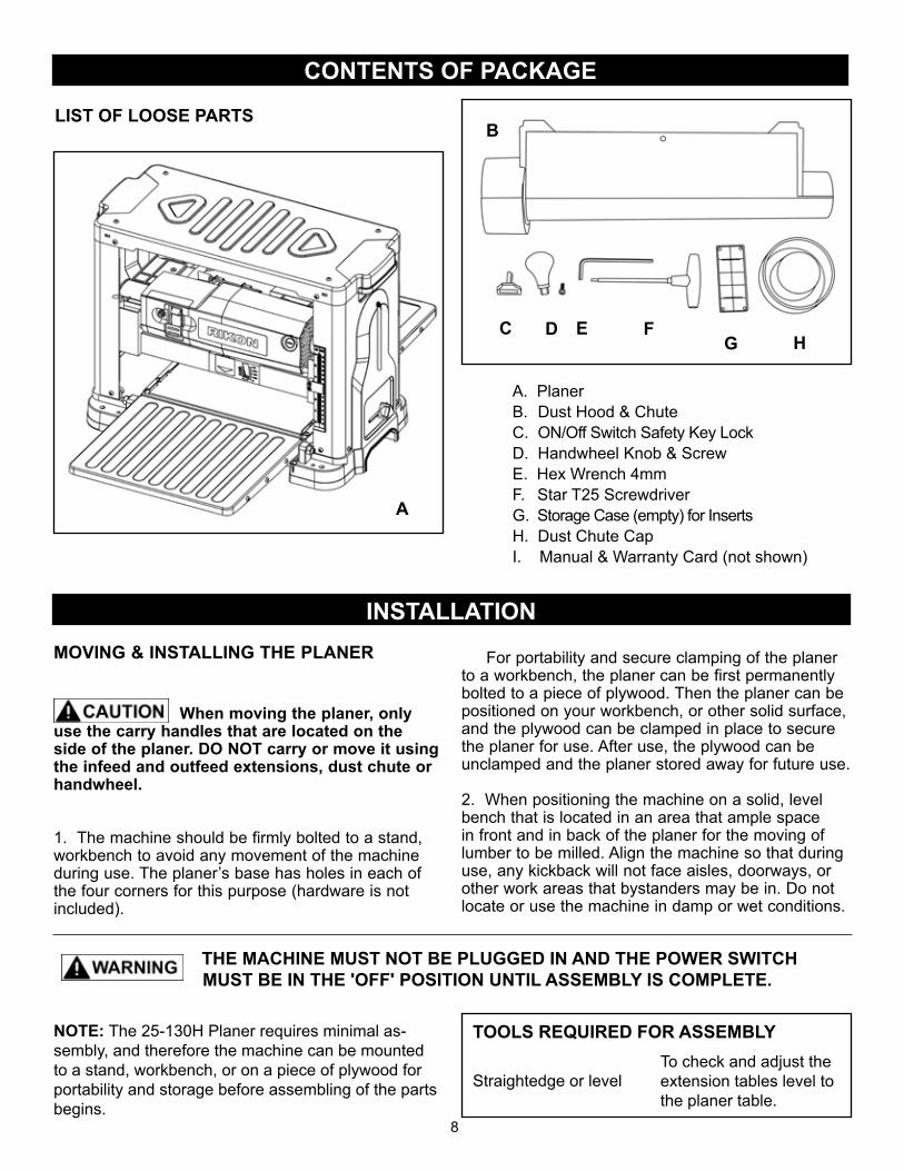
A. PlanerB. Dust Hood & ChuteC. ON/Off Switch Safety Key Lock D. Handwheel Knob & ScrewE. Hex Wrench 4mm F. Star T25 ScrewdriverG. Storage Case (empty) for InsertsH. Dust Chute CapI. Manual & Warranty Card (not shown)
LIST OF LOOSE PARTS
INSTALLATION
B
DG H
EC F
A
MOVING & INSTALLING THE PLANER
When moving the planer, only use the carry handles that are located on the side of the planer. DO NOT carry or move it using the infeed and outfeed extensions, dust chute or handwheel.
1. The machine should be firmly bolted to a stand, workbench to avoid any movement of the machine during use. The planer’s base has holes in each of the four corners for this purpose (hardware is not included).
For portability and secure clamping of the planer to a workbench, the planer can be first permanently bolted to a piece of plywood. Then the planer can be positioned on your workbench, or other solid surface, and the plywood can be clamped in place to secure the planer for use. After use, the plywood can be unclamped and the planer stored away for future use.
2. When positioning the machine on a solid, level bench that is located in an area that ample space in front and in back of the planer for the moving of lumber to be milled. Align the machine so that during use, any kickback will not face aisles, doorways, or other work areas that bystanders may be in. Do not locate or use the machine in damp or wet conditions.
THE MACHINE MUST NOT BE PLUGGED IN AND THE POWER SWITCH MUST BE IN THE 'OFF' POSITION UNTIL ASSEMBLY IS COMPLETE.
NOTE: The 25-130H Planer requires minimal as-sembly, and therefore the machine can be mounted to a stand, workbench, or on a piece of plywood for portability and storage before assembling of the parts begins.
TOOLS REQUIRED FOR ASSEMBLY
Straightedge or levelTo check and adjust theextension tables level to the planer table.
9
ASSEMBLY
COVERRAILS
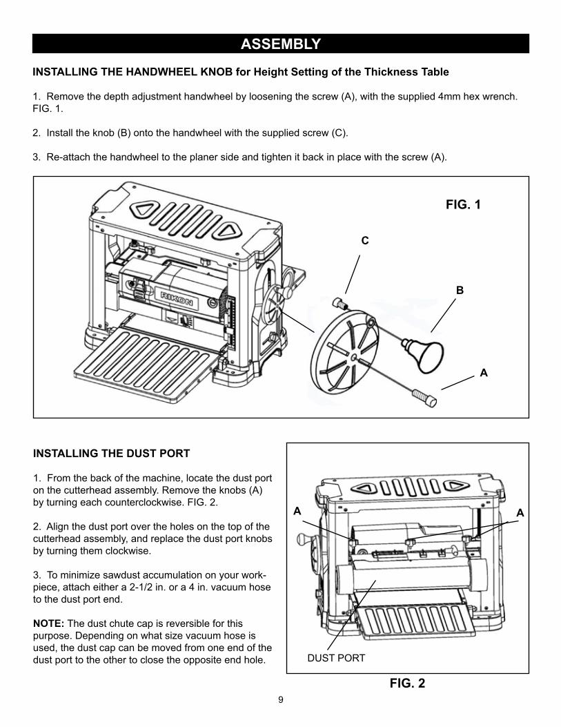
INSTALLING THE HANDWHEEL KNOB for Height Setting of the Thickness Table
1. Remove the depth adjustment handwheel by loosening the screw (A), with the supplied 4mm hex wrench. FIG. 1.
2. Install the knob (B) onto the handwheel with the supplied screw (C).
3. Re-attach the handwheel to the planer side and tighten it back in place with the screw (A).
FIG. 1
B
A
C
INSTALLING THE DUST PORT
1. From the back of the machine, locate the dust port on the cutterhead assembly. Remove the knobs (A) by turning each counterclockwise. FIG. 2.
2. Align the dust port over the holes on the top of the cutterhead assembly, and replace the dust port knobs by turning them clockwise.
3. To minimize sawdust accumulation on your work-piece, attach either a 2-1/2 in. or a 4 in. vacuum hose to the dust port end.
NOTE: The dust chute cap is reversible for this purpose. Depending on what size vacuum hose is used, the dust cap can be moved from one end of the dust port to the other to close the opposite end hole.
FIG. 2
A A
DUST PORT
10
ADJUSTMENTS
FIG. 4
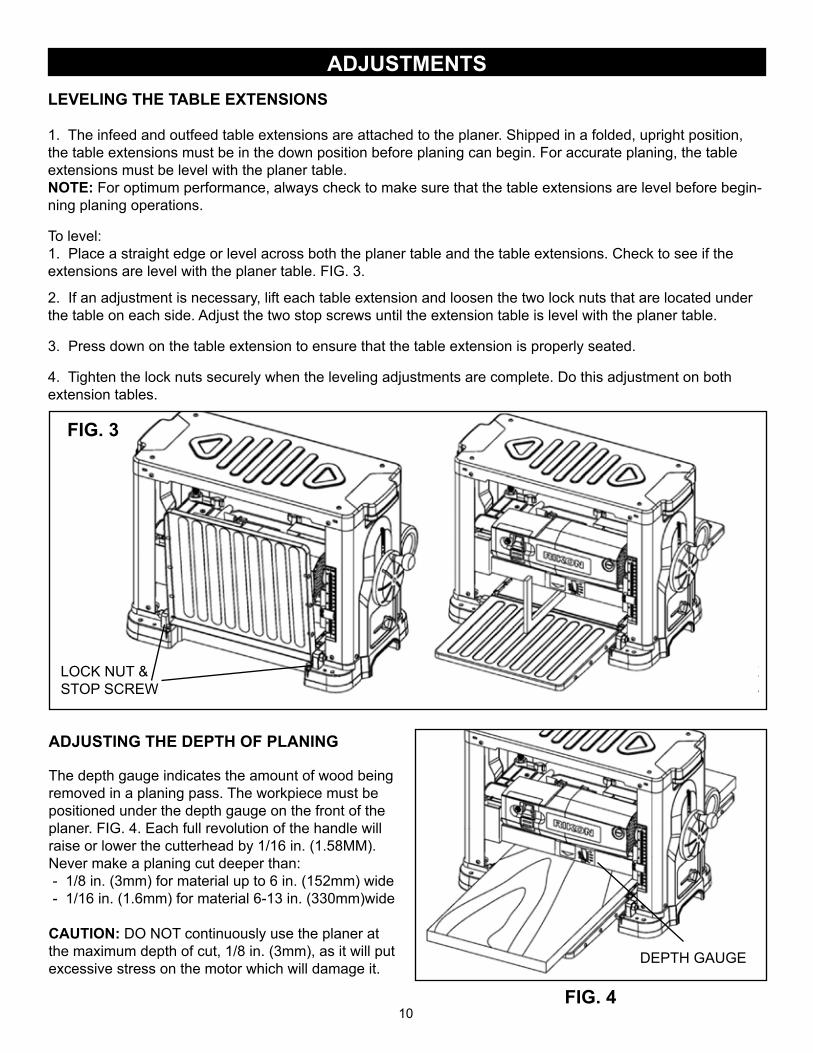
LEVELING THE TABLE EXTENSIONS
1. The infeed and outfeed table extensions are attached to the planer. Shipped in a folded, upright position, the table extensions must be in the down position before planing can begin. For accurate planing, the table extensions must be level with the planer table.NOTE: For optimum performance, always check to make sure that the table extensions are level before begin-ning planing operations.
To level:1. Place a straight edge or level across both the planer table and the table extensions. Check to see if the extensions are level with the planer table. FIG. 3.
2. If an adjustment is necessary, lift each table extension and loosen the two lock nuts that are located under the table on each side. Adjust the two stop screws until the extension table is level with the planer table.
3. Press down on the table extension to ensure that the table extension is properly seated.
4. Tighten the lock nuts securely when the leveling adjustments are complete. Do this adjustment on both extension tables.
ADJUSTING THE DEPTH OF PLANING
The depth gauge indicates the amount of wood being removed in a planing pass. The workpiece must be positioned under the depth gauge on the front of the planer. FIG. 4. Each full revolution of the handle will raise or lower the cutterhead by 1/16 in. (1.58MM).Never make a planing cut deeper than: - 1/8 in. (3mm) for material up to 6 in. (152mm) wide - 1/16 in. (1.6mm) for material 6-13 in. (330mm)wide
CAUTION: DO NOT continuously use the planer at the maximum depth of cut, 1/8 in. (3mm), as it will put excessive stress on the motor which will damage it.
DEPTH GAUGE
LEVEL TABLEWITH EXTENSIONS
LOCK NUT &STOP SCREW
FIG. 3

11
ADJUSTMENTSREPLANING using the REPEAT CUT
1. Remove the screws to take off the handwheel (1 screw), right side panel (4 screws) and top cover (4 screws). FIG. 5.
2. Lower the cutterhead assem-bly until the stop screw stops on the step block.
3. Plane a scrap piece of wood, then measure the thickness of the finished piece. It should be the same as the thickness scale and repeat cut indicator.
4. If an adjustment is neces-sary, use a wrench to loosen the lock nut and adjust the stop screw to correct the height.
5. Once the adjustment is made, retighten the lock nut and the stop screw securely.
THICKNESS SCALE ADJUSTMENT
Located on the right front of the planer, the thickness scale shows the depth of the finished workpiece. Inaccurate cuts can be prevented by routinely checking the alignment of the thickness scale.
1. Table extensions must be level with planer table.
2. Plane a scrap piece of wood, then measure the thickness of the finished piece.
3. If properly adjusted, the thickness of the finished piece should be the same as indicated on the scale.
4. If out of adjustment, loosen the two screws holding the scale indicator and adjust the scale indicator, up or down, to point to the correct setting on the scale.
5. Retighten the two scale indicator screws securely.
THICKNESSSCALE
SCALE INDICATOR& SCREWS
6. Install the right side panel, top cover and handwheel back onto the planer.
FIG. 5
FIG. 6
THE MACHINE MUST NOT BE PLUGGED IN AND THE POWER SWITCH MUST BE IN THE OFF POSITION UNTIL ALL ADJUSTMENTS ARE COMPLETE.
LOCKNUT
STOPSCREW
HANDWHEEL
REPEAT CUTINDICATORSTEP BLOCK
STEPBLOCK
OPERATIONThis machine is intended for surface thickness planing of natural, solid woods to a desired thickness, whilecreating a smooth, level surface. Thickness of each cut will depend on type of wood (hardwood versus soft-wood), width of workpiece, straightness, dryness, and grain composition. Whenever working with a new type of wood, make thin test cuts on a scrap piece of wood first to determine potential problems with the work-piece. The permissible workpiece dimensions must be observed. Any other use not as specified, including modification of the machine or use of parts not tested and approved by the equipment manufacturer can cause unforeseen damage.
PLANING
• Thickness planers work best if at least one side of the workpiece has a flat surface. When both sides of a workpiece are rough, use a surface planer or jointer first to define the initial flat surface. Plane one side of the workpiece then flip the workpiece and plane the surface of the reverse side.
• Always plane both sides of a workpiece to reach the desired thickness. This will leave the workpiece with uniform moisture to prevent warp during the drying process.
• When one end of the workpiece is thicker than the opposite end by more than 1/8 in. (3mm), make several cuts with the planer starting with light planing cuts first. light cuts create a finer finish than heavier cuts.
• Do not plane a workpiece less than 3/16 inch (5mm) thick.• Do not lower the cutterhead assembly lower than 3/16 inch (5mm).• Do not plane a workpiece less than 3/4 inch (19mm) wide.• Do not plane workpiece shorter than 7 inch (177.8mm) long. Short boards should be planed end to end
with other boards to prevent kick-back and snipe.• Boards longer than 24” should have additional support as they enter and exit the planer, so that they do not
tip up or down, causing snipe on the ends.• Do not plane more than one workpiece at a time.• Run boards through the planer at different positions along the width of the bed to utilize all of the insert
cutters along the length of the cutterhead. Planing only in the center, or through one side of the planer, will quickly dull the knives in that area.
• ALWAYS keep the cutter inserts sharp for best cutting results.
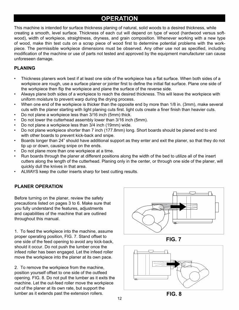
PLANER OPERATION
Before turning on the planer, review the safety precautions listed on pages 3 to 6. Make sure that you fully understand the features, adjustments and capabilities of the machine that are outlined throughout this manual.
1. To feed the workpiece into the machine, assume proper operating position, FIG. 7. Stand offset to one side of the feed opening to avoid any kick-back, should it occur. Do not push the lumber once the infeed roller has been engaged. Let the infeed roller move the workpiece into the planer at its own pace.
2. To remove the workpiece from the machine, position yourself offset to one side of the outfeed opening. FIG. 8. Do not pull the lumber as it exits the machine. Let the out-feed roller move the workpiece out of the planer at its own rate, but support the lumber as it extends past the extension rollers. FIG. 8
FIG. 7
12
13
OPERATION
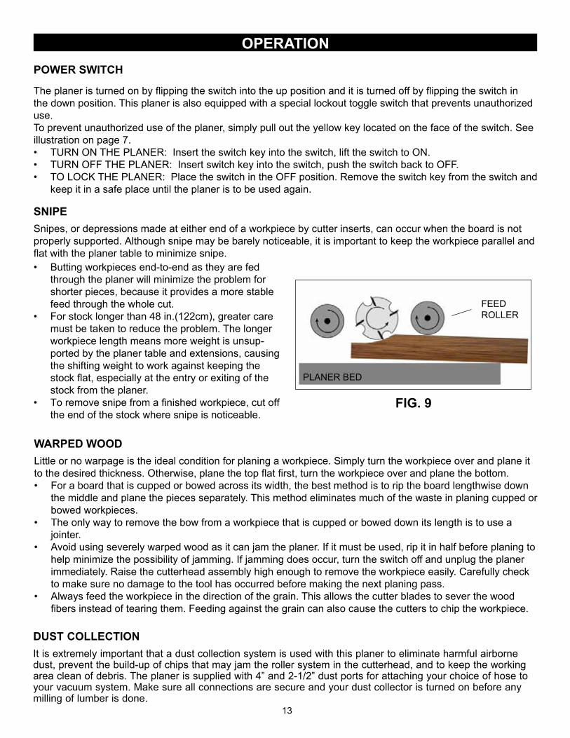
SNIPESnipes, or depressions made at either end of a workpiece by cutter inserts, can occur when the board is not properly supported. Although snipe may be barely noticeable, it is important to keep the workpiece parallel and flat with the planer table to minimize snipe.
POWER SWITCH
The planer is turned on by flipping the switch into the up position and it is turned off by flipping the switch inthe down position. This planer is also equipped with a special lockout toggle switch that prevents unauthorized use. To prevent unauthorized use of the planer, simply pull out the yellow key located on the face of the switch. See illustration on page 7.• TURN ON THE PLANER: Insert the switch key into the switch, lift the switch to ON.• TURN OFF THE PLANER: Insert switch key into the switch, push the switch back to OFF.• TO LOCK THE PLANER: Place the switch in the OFF position. Remove the switch key from the switch and
keep it in a safe place until the planer is to be used again.
FIG. 9
FEEDROLLER
PLANER BED
• Butting workpieces end-to-end as they are fed through the planer will minimize the problem for shorter pieces, because it provides a more stable feed through the whole cut.
• For stock longer than 48 in.(122cm), greater care must be taken to reduce the problem. The longer workpiece length means more weight is unsup-ported by the planer table and extensions, causing the shifting weight to work against keeping the stock flat, especially at the entry or exiting of the stock from the planer.
• To remove snipe from a finished workpiece, cut off the end of the stock where snipe is noticeable.
WARPED WOODLittle or no warpage is the ideal condition for planing a workpiece. Simply turn the workpiece over and plane it to the desired thickness. Otherwise, plane the top flat first, turn the workpiece over and plane the bottom.• For a board that is cupped or bowed across its width, the best method is to rip the board lengthwise down
the middle and plane the pieces separately. This method eliminates much of the waste in planing cupped or bowed workpieces.
• The only way to remove the bow from a workpiece that is cupped or bowed down its length is to use a jointer.
• Avoid using severely warped wood as it can jam the planer. If it must be used, rip it in half before planing to help minimize the possibility of jamming. If jamming does occur, turn the switch off and unplug the planer immediately. Raise the cutterhead assembly high enough to remove the workpiece easily. Carefully check to make sure no damage to the tool has occurred before making the next planing pass.
• Always feed the workpiece in the direction of the grain. This allows the cutter blades to sever the wood fibers instead of tearing them. Feeding against the grain can also cause the cutters to chip the workpiece.
DUST COLLECTIONIt is extremely important that a dust collection system is used with this planer to eliminate harmful airborne dust, prevent the build-up of chips that may jam the roller system in the cutterhead, and to keep the working area clean of debris. The planer is supplied with 4” and 2-1/2” dust ports for attaching your choice of hose to your vacuum system. Make sure all connections are secure and your dust collector is turned on before any milling of lumber is done.
MAINTENANCE
14FIG. 18
THE MACHINE MUST NOT BE PLUGGED IN AND THE POWER SWITCH MUST BE IN THE 'OFF' POSITION UNTIL ADJUSTMENTS ARE COMPLETE.
ROTATING OR REPLACING KNIFE INSERTS
This machine has a cutterhead with 6 rows of High Speed Steel knife inserts. Each of the 26 inserts on the cutterhead are indexed and have two sharpened sides. If the knives become dull, or one becomes nicked, simply loosen the retaining screws with the supplied star head screwdriver, lift up and rotate the inserts 90° to a new sharpened edge. No setting is required, as the cutterhead has been machined to automatically index and set the inserts in proper position for use. When both sides of an insert are dull, the insert can be easily removed and a new knife insert placed in the location. To rotate or remove an knife insert:
1. Unplug power cable, put the switch to OFF and remove the safety key.
2. Lower the upper frame motor housing to the lowest position near the planer bed by turning the handwheel.
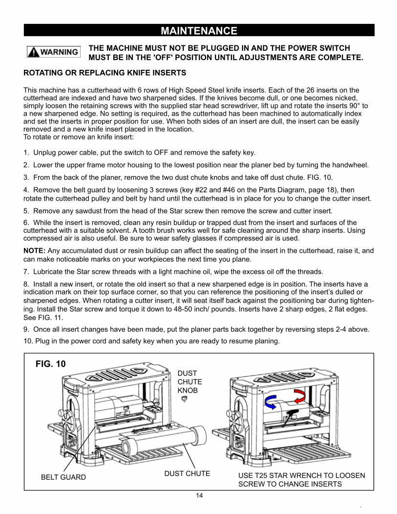
3. From the back of the planer, remove the two dust chute knobs and take off dust chute. FIG. 10.
4. Remove the belt guard by loosening 3 screws (key #22 and #46 on the Parts Diagram, page 18), then rotate the cutterhead pulley and belt by hand until the cutterhead is in place for you to change the cutter insert.
5. Remove any sawdust from the head of the Star screw then remove the screw and cutter insert.6. While the insert is removed, clean any resin buildup or trapped dust from the insert and surfaces of the cutterhead with a suitable solvent. A tooth brush works well for safe cleaning around the sharp inserts. Using compressed air is also useful. Be sure to wear safety glasses if compressed air is used.
NOTE: Any accumulated dust or resin buildup can affect the seating of the insert in the cutterhead, raise it, and can make noticeable marks on your workpieces the next time you plane.
7. Lubricate the Star screw threads with a light machine oil, wipe the excess oil off the threads.
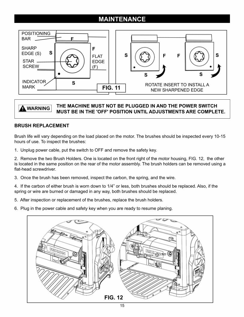
8. Install a new insert, or rotate the old insert so that a new sharpened edge is in position. The inserts have a indication mark on their top surface corner, so that you can reference the positioning of the insert’s dulled or sharpened edges. When rotating a cutter insert, it will seat itself back against the positioning bar during tighten-ing. Install the Star screw and torque it down to 48-50 inch/ pounds. Inserts have 2 sharp edges, 2 flat edges. See FIG. 11.9. Once all insert changes have been made, put the planer parts back together by reversing steps 2-4 above.10. Plug in the power cord and safety key when you are ready to resume planing.
FIG. 10
DUST CHUTE
DUSTCHUTE KNOB
BELT GUARD USE T25 STAR WRENCH TO LOOSEN SCREW TO CHANGE INSERTS
MAINTENANCE
BRUSH REPLACEMENT
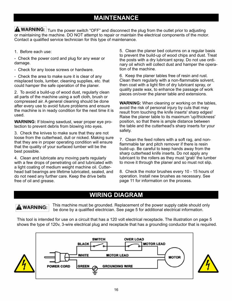
Brush life will vary depending on the load placed on the motor. The brushes should be inspected every 10-15hours of use. To inspect the brushes:
1. Unplug power cable, put the switch to OFF and remove the safety key.
2. Remove the two Brush Holders. One is located on the front right of the motor housing, FIG. 12, the other is located in the same position on the rear of the motor assembly. The brush holders can be removed using a flat-head screwdriver.
3. Once the brush has been removed, inspect the carbon, the spring, and the wire.
4. If the carbon of either brush is worn down to 1/4” or less, both brushes should be replaced. Also, if the spring or wire are burned or damaged in any way, both brushes should be replaced.
5. After inspection or replacement of the brushes, replace the brush holders.
6. Plug in the power cable and safety key when you are ready to resume planing.
FIG. 12
STARSCREW
SHARPEDGE (S)
S
SF
F
THE MACHINE MUST NOT BE PLUGGED IN AND THE POWER SWITCH MUST BE IN THE 'OFF' POSITION UNTIL ADJUSTMENTS ARE COMPLETE.
15
FIG. 11
FLATEDGE (F)
INDICATORMARK ROTATE INSERT TO INSTALL A
NEW SHARPENED EDGE
POSITIONINGBAR
S
S S
SF F
16
This machine must be grounded. Replacement of the power supply cable should only be done by a qualified electrician. See page 5 for additional electrical information.
WIRING DIAGRAM
MAINTENANCE
1. Before each use:- Check the power cord and plug for any wear or damage.- Check for any loose screws or hardware.- Check the area to make sure it is clear of any misplaced tools, lumber, cleaning supplies, etc. that could hamper the safe operation of the planer.2. To avoid a build-up of wood dust, regularly clean all parts of the machine using a soft cloth, brush or compressed air. A general cleaning should be done after every use to avoid future problems and ensure the machine is in ready condition for the next time it is used.WARNING: If blowing sawdust, wear proper eye pro-tection to prevent debris from blowing into eyes.3. Check the knives to make sure that they are not loose from the cutterhead, dull or nicked. Making sure that they are in proper operating condition will ensure that the quality of your surfaced lumber will be the best possible.4. Clean and lubricate any moving parts regularly with a few drops of penetrating oil and lubricated with a light coating of medium weight machine oil. Cutter-head ball bearings are lifetime lubricated, sealed, and do not need any further care. Keep the drive belts free of oil and grease.
Turn the power switch “OFF” and disconnect the plug from the outlet prior to adjusting or maintaining the machine. DO NOT attempt to repair or maintain the electrical components of the motor. Contact a qualified service technician for this type of maintenance.
5. Clean the planer bed columns on a regular basis to prevent the build-up of wood chips and dust. Treat the posts with a dry lubricant spray. Do not use ordi-nary oil which will collect dust and hamper the opera-tion of the machine.6. Keep the planer tables free of resin and rust. Clean them regularly with a non-flammable solvent, then coat with a light film of dry lubricant spray, or quality paste wax, to enhance the passage of work pieces on/over the planer table and extensions.
WARNING: When cleaning or working on the tables, avoid the risk of personal injury by cuts that may result from touching the knife inserts' sharp edges! Raise the planer table to its maximum 'up/thickness' position, so that there is ample distance between the table and the cutterhead's sharp inserts for your safety.
7. Clean the feed rollers with a soft rag, and non-flammable tar and pitch remover if there is resin build-up. Be careful to keep hands away from the sharp cutterhead knife inserts. Do not apply any lubricant to the rollers as they must 'grab' the lumber to move it through the planer and so must not slip.
8. Check the motor brushes every 10 - 15 hours of operation. Install new brushes as necessary. See page 11 for information on the process.
This tool is intended for use on a circuit that has a 120 volt electrical receptacle. The illustration on page 5 shows the type of 120v, 3-wire electrical plug and receptacle that has a grounding conductor that is required.

17
TROUBLESHOOTING
FOR YOUR OWN SAFETY, ALWAYS TURN OFF AND UNPLUG THE MACHINE BEFORE CARRYING OUT ANY TROUBLESHOOTING.
For parts or technical questions contact: [email protected] or 877-884-5167.
SYMPTOM POSSIBLE CAUSES SOLUTIONSPlaner will not start. 1. No power
2. Blown shop fuse3. Main on/off switch is not working or the safety key is not inserted4. Motor failure
1. Check power source, plug and wiring.2. Check fuse, replace if it is blown.3. Check position of the switches. Contact local dealer for repair or replacement.4. Inspect motor for failed components. Contact Dealer for repair or replacement.
Shop’s Circuit Breakers trip and /or Fuses are blown
1. Wrong circuit size for machine2. Motor is overloaded under strain from taking too heavy of cut3. Use of a long extension cord
1. Check circuit/fuse rating and amps of the motor. Install CORRECT rated breaker/fuse.2. Take lighter cuts in planing lumber.3. No extension cord, or use higher gauge.
Planer feed rate and cutting is not consistent
1. Chips, resin and dust build-up on the planer tables and parts.
1. Unplug planer from the power source and clean the planer parts.
Planed lumber thickness does not match the thick-ness scale indicator
1. Indicator scale is not set correctly.
1. Adjust thickness scale indicator.
Small raised lines are running along the surface
1. Knives are nicked or broken 1. Rotate insert knives to new sharp edges.
Snipe on board ends(NOTE: Snipe can be reduced, but not fully eliminated )
1. Lumber not supported when fed into or exiting the planer2. Short boards not butted
1. Support long boards with roller stands.2. Run boards butt end to end through the planer.
Planed surface is torn 1. Cutting against the grain2. Cut is too deep3. Knives are dull
1. Cut with the grain. For figured woods, take shallow cuts to minimize tear out.2. Reduce cutting depth to 1/16" or less.3. Rotate insert knives to new sharp edges.
Planed surface grain is rough, raised or fuzzy
1. Lumber has a high moisture content2. Cut is too deep3. Knives are dull
1. Reduce the moisture content by drying it, or plane other properly seasoned lumber.2. Reduce cutting depth to 1/16” or less.3. Rotate insert knives to new sharp edges.
Planed surface is glossy 1. Cutting depth is too shallow2. Knives are dull
1. Increase depth of cut slightly.2. Rotate insert knives to new sharp edges.

18
PARTS DIAGRAMN
OTE
: Ple
ase
refe
renc
e th
e M
anuf
actu
rer’s
Par
t Num
ber
whe
n ca
lling
for R
epla
cem
ent P
arts
. For
Par
ts u
nder
War
rant
y,th
e S
eria
l Num
ber o
f you
r mac
hine
is re
quire
d.

PARTS LIST
19
PART NO.
Depth gaugeScrew M5×8LStar lock washer M5Gear BoxC-ring STW15Chain wheel 8 tooth Ø15Chain #410-26SpringBlock bearingOutfeed rollerSpringPlate retainerHex socket cap screw M5XP0.8X10LInfeed rollerGear box coverGear (12T)Screw with washer M5XP0.8X10LRail guidePlate wearExtension tableWasher Ø5.3×Ø12×1.5Washer Ø5.3×Ø16×1.5tBall bearing 6001zzTurning shaftScaleSpacer Ø10.5×Ø18×12tStep blockStep block pinHex nut M6XP1.0SpringSteel ballPivot rodAdjusting screwHex NutSpring platePan hd screw w/ washer M5XP0.8X10LHex screw M6XP1.0X25LHex nut M6XP1.0Ball bearing 6000zzWasher Ø4.2×Ø15×2tHex socket cap screw M4XP0.7X12LChain #410-24Chain #410-116Hex socket button screw M5XP0.8X25LHex socket cap screw M5XP0.8X16LC-ring STW12Washer Ø10.3×Ø18×1tHex socket button screw M5xP0.8x12LSpring washer Ø5.3×Ø8×1tWasher Ø19.8×Ø23.5×0.8tLogo labelSpecification labelSide plateRepeat cut labelSafety warning labelBushingWasherSpringBevel gearMotor assembly
P25-130H-79P25-130H-87P25-130H-88P25-130H-89P25-130H-90P25-130H-91P25-130H-92P25-130H-93P25-130H-94P25-130H-95P25-130H-96P25-130H-97P25-130H-98P25-130H-99P25-130H-100P25-130H-101P25-130H-116P25-130H-117P25-130H-118P25-130H-119P25-130H-121P25-130H-122P25-130H-123P25-130H-125P25-130H-128P25-130H-129P25-130H-130P25-130H-131P25-130H-132P25-130H-133P25-130H-134P25-130H-135P25-130H-136P25-130H-137P25-130H-138P25-130H-139P25-130H-140P25-130H-141P25-130H-142P25-130H-143P25-130H-144P25-130H-145P25-130H-146P25-130H-147P25-130H-148P25-130H-149P25-130H-155P25-130H-162P25-130H-163P25-130H-164P25-130H-191P25-130H-195P25-130H-198P25-130H-202P25-130H-203P25-130H-206P25-130H-207P25-130H-208P25-130H-209P25-130H-600
PART NO.DESCRIPTION KEY NO.
7987888990919293949596979899100101116117118119121122123125128129130131132133134135136137138139140141142143144145146147148149155162163164191195198202203206207208209600
P25-130H-1P25-130H-2P25-130H-2-1P25-130H-3P25-130H-4P25-130H-6P25-130H-7P25-130H-8P25-130H-9P25-130H-10P25-130H-10-1P25-130H-11P25-130H-11-1P25-130H-13P25-130H-14P25-130H-15P25-130H-16P25-130H-17P25-130H-19P25-130H-20P25-130H-21P25-130H-22P25-130H-25P25-130H-26P25-130H-27P25-130H-28P25-130H-32P25-130H-33P25-130H-34P25-130H-36P25-130H-37P25-130H-38P25-130H-41P25-130H-43P25-130H-44P25-130H-45P25-130H-46P25-130H-47P25-130H-48P25-130H-49P25-130H-50P25-130H-51P25-130H-54P25-130H-55P25-130H-61P25-130H-63P25-130H-65P25-130H-66P25-130H-67P25-130H-68P25-130H-69P25-130H-70P25-130H-71P25-130H-72P25-130H-73P25-130H-74P25-130H-75P25-130H-76P25-130H-77P25-130H-78
Top coverHex socket button screw M6xP1.0x8LHex socket button screw M6xP1.0x10LRetainer bearing for top coverElevation nut 19.85mmUpper frameLeft side panelRight side panelKnobHandwheelScrew with washer M5XP0.8X20LKnobHex socket cap screw M5XP0.8X10LIdlerIdler shaftThreaded screw postBevel gearBushingBaseHex wrench 4mmx100mmStar wrench T25 5mmBelt guardPointerBlock guardCutterhead pulleyPlateHandwheel bracketChain wheelDust port assemblyDust port ABSDust port cover ABSSpecial washer Ø12.5×Ø25.8×2tKnobHex socket button screw M6xP1.0x12LWasher Ø6.5×Ø20×2tDrive rodPhillips screw M4XP0.7X10L ODØ10Screw M5XP0.8X8LChip deflectorScrew M5XP0.8X8LScrew M5×P0.8×10L ODØ10Cord clamp GCL-5/16 SWasher Ø8.5×Ø18×2tHex socket buttn screw M8×P1.25×20LKey 5×12LRetainer bearingMotor pulleyV-belt 135J6Hex nut M16XP2.0L.HBall bearing 6203ZZCutter insert - 2 edgesHelical cutterheadStar screw M5xP0.8x9.6LHex nut M10x14xP1.5Thickness adjusting rodHex nut M5XP0.8Adjust screw M5XP0.8X25LScrew M5XP0.8X6LPhillips button screw M3XP0.5X22LHex socket button screw M5×P0.8×12L
DESCRIPTION KEY NO.
122-13467891010-11111-11314151617192021222526272832333436373841434445464748495051545561636566676869707172737475767778

PARTS DIAGRAM
20
NO
TE: P
leas
e re
fere
nce
the
Par
t Num
ber w
hen
calli
ngfo
r Rep
lace
men
t Par
ts.
For P
arts
und
er W
arra
nty,
the
Ser
ial N
umbe
r of y
our
mac
hine
is re
quire
d.
MO
TOR
ASS
EMB
LY

PARTS LIST
21
NO
TE: P
leas
e re
fere
nce
the
Par
t Num
ber w
hen
calli
ng fo
r Rep
lace
men
t Par
ts.
For P
arts
und
er W
arra
nty,
the
Ser
ial N
umbe
r of y
our m
achi
ne is
requ
ired.
MO
TOR
ASS
EMB
LY
PAR
T N
O.
Mot
or c
over
(rea
r)
Wav
e lo
ck w
ashe
r
Ball
bear
ing
620
1LLB
Rot
or a
ssem
bly
120
V
Plas
tic c
over
Tap
scre
w
M4.
8X70
mm
Stat
or a
ssem
bly
120
V
Brus
h ho
lder
Brus
h 1
05S
Brus
h co
ver
Mot
or h
ousi
ng
C-R
ing
RTW
32
Nyl
ock
scre
w M
5X12
mm
Lead
wire
10
15#1
4AW
G, 8
0mm
+250
T
Lock
was
her
P25-
130H
-180
P25-
130H
-181
P25-
130H
-182
P25-
130H
-183
P25-
130H
-184
P25-
130H
-185
P25-
130H
-187
P25-
130H
-188
P25-
130H
-189
P25-
130H
-190
P25-
130H
-192
P25-
130H
-193
P25-
130H
-194
P25-
130H
-196
P25-
130H
-197
PAR
T N
O.
DES
CR
IPTI
ON
KEY
NO
.
180
181
182
183
184
185
187
188
189
190
192
193
194
196
197
P25-
130H
-160
P25-
130H
-161
P25-
130H
-163
P25-
130H
-165
P25-
130H
-166
P25-
130H
-167
P25-
130H
-168
P25-
130H
-170
P25-
130H
-171
P25-
130H
-172
P25-
130H
-173
P25-
130H
-174
P25-
130H
-175
P25-
130H
-176
P25-
130H
-177
P25-
130H
-178
Pow
er c
ord
Pow
er c
ord
bush
ing
HAL
O(6
P3-4
)
Was
her
5.3
×8×1
t
Scre
w p
an h
ead
Philli
ps M
5X20
mm
Switc
h bo
x
Win
dbre
ak
Scre
w
Elec
trica
l pro
tect
or
20A,
A-0
701
Switc
h pa
ddle
Switc
h sa
fety
key
On/
Off
switc
h
Mot
or p
in
Tap
scre
w
M5X
8mm
Gro
undi
ng w
ire 1
015#
14AW
G, 3
00m
m+5
R
Exte
rnal
toot
h w
ashe
r M
5
Tap
scre
w
M4.
2X20
mm
DES
CR
IPTI
ON
KEY
NO
.
160
161
163
165
166
167
168
170
171
172
173
174
175
176
177
178

NOTESUse this section to record maintenance, service and any calls to Technical Support:
ACCESSORIES
25-499 HSS INSERT CUTTERS - Pack of 10 with 2 pre-sharpened edges25-499C CARBIDE INSERT CUTTERS - PK 10 with 2 pre-sharpened edges
22
ADDITIONAL PLANER ACCESSORIES
For addtional accessories for use with the 25-130H thickness planer, contact your
local RIKON distributor, or visit the RIKON website at www.rikontools.com.
There you will find Dust Collectors, Dust Hose, Stands, Mobile Bases and other parts and accessories for the RIKON
machinery in your shop.

23
WARRANTY

www.rikontools.com25-130HM2
25-130H
For more information:16 Progress RoadBillerica, MA 01821
877-884-5167 / [email protected]