Embed Size (px)
Citation preview

Lesson 13: Water and Sewer Utility Design
Water-Sewer Utility Design © 2005 Bentley Systems, Incorporated Do Not Duplicate
13-1
13
WELCOME! This lesson is about performing Water and Sewer utility design. Now that you have designed the roadways and drainage, PowerCivil has a multitude of tools that allow you to perform water and sewer plan and profile design. In this lesson you will learn how to utilize the tools for the design of water and wastewater systems.
LESSON OBJECTIVES In this lesson, the topics covered include:
• Topic 1 Sewer Lines – locating and creating sewer pipes • Topic 2 Sewer Nodes – locating sewer structures • Topic 3 Sewer Profiles – creating, designing and modifying sewer profiles • Topic 3 Water Lines – locating and creating water lines • Topic 4 Water Nodes – locating water structures • Topic 5 Water Profiles – creating, designing and modifying water profiles Be sure to have a look at the context sensitive help for PowerCivil. Either while using the tutorial or in general practice with the software, you will find the help system not only includes program documentation but it also is equipped with links to online video clips (internet connection is required). Access the help from the menu bar under Help>Civil Help.
INTRODUCTION This Lesson will show you how to perform water and sewer design for the project with the PowerCivil Utility tools. With the Utility tools you can design water and wastewater systems and create reports based various design constraints and input parameters.
The Utility Tools provide you with many ways to design and automatically compute the water and sewer amenities of the site.
From the desktop, launch PowerCivil from the program icon, navigate to the folder for Lesson 13 and then open the file “WATSEW.DGN”.
To view this portion of the lesson, press the play button.
The “WATSEW.DGN” file contains pertinent base planimetrics as required for completion of the water and sewer design.
Sewer Lines
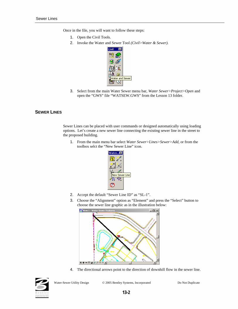
Once in the file, you will want to follow these steps:
1. Open the Civil Tools. 2. Invoke the Water and Sewer Tool (Civil>Water & Sewer).
3. Select from the main Water Sewer menu bar, Water Sewer>Project>Open and
open the “GWS” file “WATSEW.GWS” from the Lesson 13 folder.
SEWER LINES
Sewer Lines can be placed with user commands or designed automatically using loading options. Let’s create a new sewer line connecting the existing sewer line in the street to the proposed building.
1. From the main menu bar select Water Sewer>Lines>Sewer>Add, or from the toolbox selct the “New Sewer Line” icon.
2. Accept the default “Sewer Line ID” as “SL-1”. 3. Choose the “Alignment” option as “Element” and press the “Select” button to
choose the sewer line graphic as in the illustration below:
4. The directional arrows point to the direction of downhill flow in the sewer line.
Water-Sewer Utility Design © 2005 Bentley Systems, Incorporated Do Not Duplicate
13-2

Sewer Nodes
5. Click once again to accept the flow direction. 6. In the “Size” group box, “Design By:” option to “Library Defined Pipe” with the
following parameters.
Type: PVC Item 6” Sewer Minimum Clearance 2.0
7. Click the “Apply” button to accept the sewer line into the project.
SEWER NODES
Sewer Nodes are used to represent sewer structures in the project. Let’s add manholes along the sewer line we just created.
1. From the main menu bar select Water Sewer>Node>Sewer>Add, or from the toolbox select the “Add Sewer Node” icon.
Water-Sewer Utility Design © 2005 Bentley Systems, Incorporated Do Not Duplicate
13-3

Sewer Nodes
2. Accept the “Node ID” as “SN-1” and toggle “ON” the “Auto Locate Sewer
Node” option in order to automatically locate the sewer nodes along the sewer line. Press the “OK” button.
3. Select the “Location” tab and use the following dialog box settings:
4. In the “Payitem” group box, select the “Item ID” for the manhole structure as
“4’ Dia 6’ deep WW MH”. 5. Select the Sewer Line as “SL-1”. 6. Toggle “ON” Critical points to place additional manholes at all element vertices. 7. Toggle “ON” Node Interval and set it to “200” to place additional manholes at
the specified interval. 8. Toggle “ON” Divide Evenly to force the node interval evenly along the sewer
line length.
Water-Sewer Utility Design © 2005 Bentley Systems, Incorporated Do Not Duplicate
13-4

Sewer Profiles
9. Select the “Elevation” tab and use the following dialog box settings:
Top Elevation: Design Surface Bottom Elevation: Range Min. Depth 3.0 Max. Depth 8.0 Align Option Soffits
10. Click the “Apply” button to initiate automatic placement of the manholes.
SEWER PROFILES Sewer profiles are automatically created to display the sewer components in a profile view. Let’s build a sewer line profile for the newly created line.
1. Select Water Sewer>Profiles>Sewer>Add, or from the toolbox, select the “New Sewer Profile” icon.
Water-Sewer Utility Design © 2005 Bentley Systems, Incorporated Do Not Duplicate
13-5
Sewer Profiles
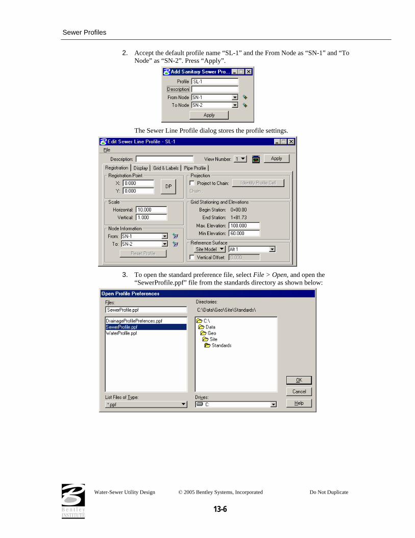
2. Accept the default profile name “SL-1” and the From Node as “SN-1” and “To
Node” as “SN-2”. Press “Apply”.
The Sewer Line Profile dialog stores the profile settings.
3. To open the standard preference file, select File > Open, and open the
“SewerProfile.ppf” file from the standards directory as shown below:
Water-Sewer Utility Design © 2005 Bentley Systems, Incorporated Do Not Duplicate
13-6

Water Lines
4. Click the “Apply” button to draw the profile at the specified Data Point:
Sewer Line changes can be made at any time by adding/deleting/modifying vertices of the sewer line graphic.
5. Open the Plan and Profile view simultaneously and watch the effects of plan view modifications to the sewer line.
WATER LINES Water Lines can be placed with user commands or selected from the library. Let’s create a new water line from the existing water line in the street to the proposed building.
To view this portion of the lesson, press the play button.
1. From the main menu, select Water Sewer>Lines>Water>Add, or from the toolbox, select the “New Water Line” icon.
Water-Sewer Utility Design © 2005 Bentley Systems, Incorporated Do Not Duplicate
13-7

Water Lines
2. Accept the default Water Line ID as “WL-1”. Press the “OK” button.
3. Choose the “Alignment” option as “Element” and press the “Select” button to
choose the water line graphic as in the illustration below:
The directional arrows point to the direction of downhill flow in the water line.
4. Click once again to accept the flow direction. 5. Click the “Apply” button after making the dialog settings shown below to accept
the sewer line into the project.
6. In the “Size” group box, set the “Design By:” option to “Library Defined Pipe”;
the “Type” to “PVC” and “Item” to “4” Water”. 7. Set the “Profile Interval” for vertical PVI’s to 25.0
Water-Sewer Utility Design © 2005 Bentley Systems, Incorporated Do Not Duplicate
13-8
Water Nodes
8. Set the “Minimum Clearance” of the water line from other utilities on the
project = 2.0’ 9. Set the “Default Depth” of the water line under the design surface = 4.0’ 10. Click Apply
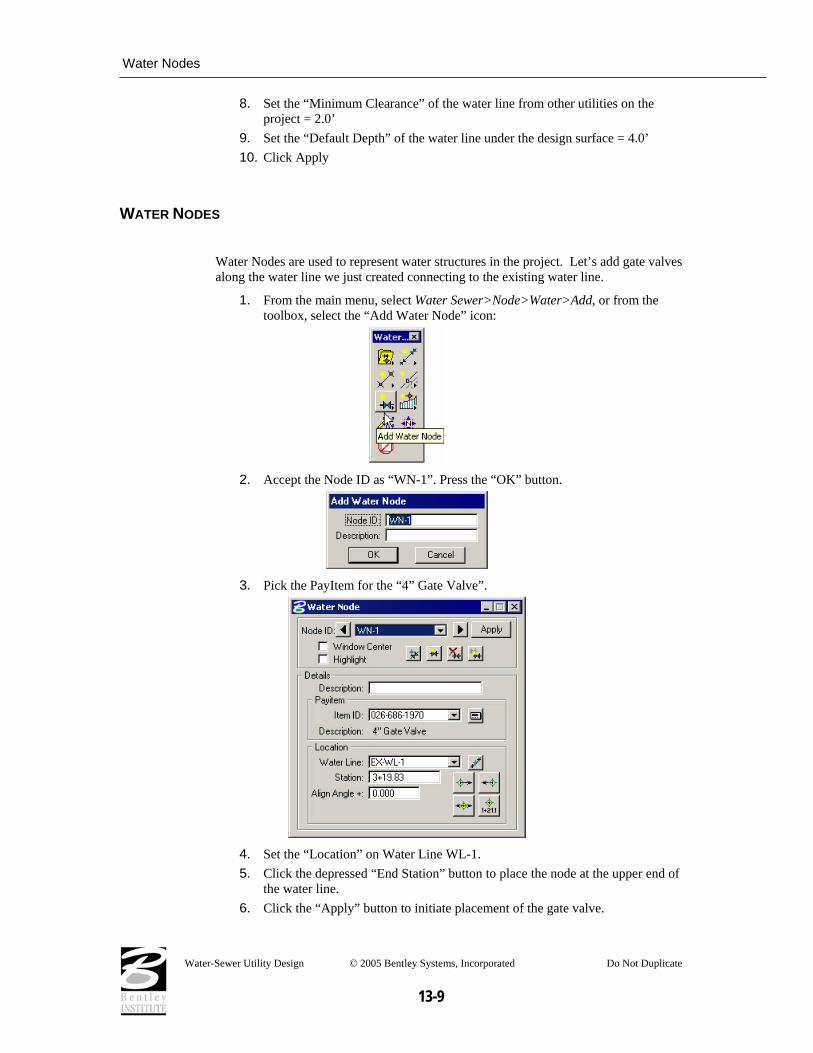
WATER NODES
Water Nodes are used to represent water structures in the project. Let’s add gate valves along the water line we just created connecting to the existing water line.
1. From the main menu, select Water Sewer>Node>Water>Add, or from the toolbox, select the “Add Water Node” icon:
2. Accept the Node ID as “WN-1”. Press the “OK” button.
3. Pick the PayItem for the “4” Gate Valve”.
4. Set the “Location” on Water Line WL-1. 5. Click the depressed “End Station” button to place the node at the upper end of
the water line. 6. Click the “Apply” button to initiate placement of the gate valve.
Water-Sewer Utility Design © 2005 Bentley Systems, Incorporated Do Not Duplicate
13-9

Water Profiles
7. Place another “4” Gate Valve” at the beginning of the water line to complete
water service to the building.
Hint Be sure to add a new node for the second gate valve.
WATER PROFILES Water profiles are automatically created to display the water components in a profile view. Let’s build a water line profile for the newly created line.
1. From the main menu, select Water Sewer>Profiles>Water>Edit List, or from the toolbox, select the “Water Line Profile List” icon.
2. Pick the newly created Water Line “WL-1” from the list and click “OK”.
3. Accept the creation of the new Water Profile by pressing the “Yes” button.
Water-Sewer Utility Design © 2005 Bentley Systems, Incorporated Do Not Duplicate
13-10

Water Profiles
4. Click the “DP” button to place the lower left-hand portion of the grid:
5. Select File > Open and open the file “WaterProfile.ppf” from the standards
folder.
Water-Sewer Utility Design © 2005 Bentley Systems, Incorporated Do Not Duplicate
13-11

Summary
6. Click “Apply” to accept the changes and draw the profile, which should match
the illustration below:
7. Edit the Water Line and reset the default depth to 3’ to avoid the conflict with
the storm sewer line. 8. Open the Plan and Profile view simultaneously and watch the effects of plan
view modifications to the water line.
SUMMARY The main points to remember are:
• Both Water and Sewer Lines accommodate standard microstation modify commands while retaining their correlation to the design principles/standards/settings of the project.
• Profiling is automatic and customizable via the profile dialogs and save features. • Plan and Profile view retain their relation and can be modified at any time during the
design process.
For more video instruction please visit the following web page… http://65.217.17.142/downloads/sitemodeler/GEOPAK%20Site%20Modeler%20Training%20Videos.htm
Water-Sewer Utility Design © 2005 Bentley Systems, Incorporated Do Not Duplicate
13-12