Embed Size (px)
Citation preview
978–0–19–957328–8 13-Helm-c13 Helm Hepburn (Typeset by SPi, Chennai) 263 of 283 June 21, 2009 12:8
13
Carbon Dioxide Capture and Storage
Howard Herzog∗
I. INTRODUCTION
Carbon dioxide capture and storage (CCS) is the capture and secure storageof carbon dioxide (CO2) that would otherwise be emitted to the atmosphere.Currently, the major CCS efforts focus on the removal of carbon dioxide directlyfrom industrial or utility plants and subsequently storing it in secure geologicreservoirs. The rationale for CCS is to enable the use of fossil fuels while reducingthe emissions of CO2 into the atmosphere, and thereby mitigating global climatechange.
At present, fossil fuels are the dominant source of the global primary energysupply, and will likely remain so for the rest of the century. Fossil fuels supply over85 per cent of all primary energy; the rest is made up of nuclear, hydro-electricity,and renewable energy (commercial biomass, geothermal, wind, and solar energy).
While great efforts and investments are made by many nations to increase theshare of renewable energy in the primary energy supply and to foster conservationand efficiency improvements of fossil-fuel usage, addressing climate-change con-cerns during the coming decades will likely require significant contributions fromCCS. In his keynote address at the 9th International Conference on GreenhouseGas Control Technologies (GHGT-9, November 2008), Jae Edmonds1 reportedthat ‘preparations for the IPCC 5th Assessment Report have indicated that meet-ing low carbon stabilization limits is only possible with CCS’.
The goals of this paper are to describe the fundamentals of CCS technology,to discuss the current status and costs of the technology, and to explore thepolicy context required for CCS to become a significant climate-change mitigationoption. The paper is divided into sections as follows. Section II describes the majorcomponents of a CCS system and their commercial use today, while section IIIdescribes the CO2 sources that are compatible with CCS. Sections IV (capture)and V (geologic storage) review the technological basis for CCS. Section VIlooks at CCS costs. Section VII comments on China and CCS, while section VIII
∗ Massachusetts Institute of Technology, Energy Initiative.
I would like to thank three of my current research assistants who have helped in preparation ofthis chapter—Eleanor Ereira, Michael Hamilton, and Ashleigh Hildebrand.
1 Chief Scientist, Joint Global Change Research Institute.

978–0–19–957328–8 13-Helm-c13 Helm Hepburn (Typeset by SPi, Chennai) 264 of 283 June 21, 2009 12:8
264 Carbon Dioxide Capture and Storage
discusses the future of CCS in the context of climate policy. Some concludingcomments and presented in section IX.
II. COMPONENTS OF A CCS SYSTEM
While there is no unique way to break down a CCS system into its componentparts, typical components include the following.
� Capture. The separation of CO2 from an effluent stream and its compressionto a liquid or supercritical2 state. In most cases today, the resulting CO2
concentration is >99 per cent, though lower concentrations may be accept-able. Capture is generally required to be able to transport and store the CO2
economically.� Transport. The movement of the CO2 from its source to the storage reservoir.
While transport by truck, train, and ship are all possible, transporting largequantities is most economically achieved with a pipeline.
� Injection. Depositing CO2 into the storage reservoir. Since the main storagereservoirs under consideration today are geological formations, these arethe focus in this paper. Other potential reservoirs include the deep ocean,ocean sediments, or mineralization (conversion of CO2 to minerals). Whilesome commercial use of CO2 may be possible, the amount that can be usedcompared to the amount of CO2 that is emitted from power plants will bevery small.
� Monitoring. Once the CO2 is in the ground, it must be monitored. Since CO2
is neither toxic nor flammable, it poses only a minimal environmental andhealth and safety risk. The main purpose of monitoring is to make sure thatthe sequestration operation is effective, meaning that almost all the CO2 staysout of the atmosphere for centuries or longer.
It should be noted that all components of a CCS system are commercial today.The challenge for CCS to be considered commercial is to integrate and scale upthese components. Below is a brief summary of the commercial use of each of theabove components. Later sections discuss the technical aspects of both captureand storage.
(i) Capture
The idea of separating and capturing CO2 from the flue gas of power plants did notoriginate out of concern about climate change. Rather, it gained attention as a pos-
2 This means compression of CO2 to above its critical pressure of 73.9 bar. At these pressures, CO2
properties (e.g. density) are more like those of a liquid than of a gas.
978–0–19–957328–8 13-Helm-c13 Helm Hepburn (Typeset by SPi, Chennai) 265 of 283 June 21, 2009 12:8
Howard Herzog 265
sible economic source of CO2, especially for use in enhanced oil recovery (EOR)operations, where CO2 is injected into oil reservoirs to increase the mobility of theoil and, thereby, the productivity of the reservoir. Several commercial CO2-captureplants were constructed in the late 1970s and early 1980s in the USA. When theprice of oil dropped in the mid-1980s, the recovered CO2 was too expensive forEOR operations, forcing the closure of these capture facilities. However, the NorthAmerican Chemical Plant in Trona, California, which uses this process to produceCO2 for carbonation of brine, started operations in 1978 and is still operatingtoday. Several more CO2-capture plants have subsequently been built to produceCO2 for commercial applications and markets.
All the above plants used post-combustion capture technology (discussedbelow). The amount of CO2 captured ranged from a few hundred tons of CO2
a day to just over a thousand tons a day. Deployment of post-combustion capturetechnologies for climate-change purposes will entail very substantial increases inscale, since a 500 MW coal-fired plant produces about 10,000 tons/day of CO2.
(ii) Transport
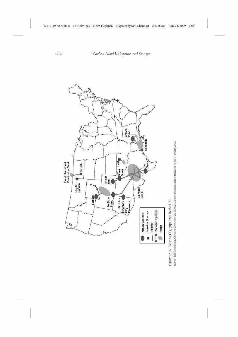
There exist over 3,400 miles of CO2 pipelines in the United States3 (seeFigure 13.1). Their main function is to transport CO2 from naturally occur-ring reservoirs to the oil fields of West Texas and the Gulf Coast for enhancedoil recovery. The Wyoming/Colorado pipelines are fed by the LaBarge naturalgas processing plant, where large quantities of CO2 need to be separated fromnatural gas in order for the natural gas to meet commercial specifications, such asheating value. The North Dakota pipeline is fed by the Great Plains Synfuels Plant,which produces synthetic natural gas from coal, with large amounts of CO2 as aby-product.
(iii) Injection
Though a relatively new idea in the context of climate-change mitigation, injectingCO2 into geological formations has been practised for many years.
Acid-gas Injection
The major purpose of these injections is to dispose of ‘acid gases’, a mixtureconsisting primarily of H2S (hydrogen sulphide) and CO2 that is a by-productof oil and gas production. Acid-gas injection projects remove CO2 and H2Sfrom the produced oil or gas stream, and compress and transport the gases viapipeline to an injection well, where they are injected into geological formations.In 2001, nearly 200m cubic metres of acid gas were injected into formations acrossAlberta and British Columbia at more than 30 different locations. In most of these
3 From the Chemical Economics Handbook (SRI Consulting).
978–0–19–957328–8 13-Helm-c13 Helm Hepburn (Typeset by SPi, Chennai) 266 of 283 June 21, 2009 12:8
266 Carbon Dioxide Capture and Storage
Figu
re13
.1.
Exi
stin
gC
O2
pipe
lines
inth
eU
SASo
urce
:SR
IC
onsu
ltin
g,C
hem
ical
Eco
nom
ics
Han
dboo
k,C
arbo
nD
ioxi
deM
arke
tR
esea
rch
Rep
ort,
Jan
uar
y20
07.
978–0–19–957328–8 13-Helm-c13 Helm Hepburn (Typeset by SPi, Chennai) 267 of 283 June 21, 2009 12:8
Howard Herzog 267
projects, CO2 represents the largest component of the acid gas, consisting of up to90 per cent of the total volume injected for some projects.
EOR
CO2 injection into geological formations for enhanced oil recovery is a maturetechnology, having begun in 1972. In 2000, 84 commercial or research-level CO2-EOR projects were operational worldwide. The United States, the technologyleader, accounts for 72 of the 84 projects, most of which are located in the PermianBasin. Combined, these projects inject over 30m tons of CO2 per year. Outsidethe United States and Canada, CO2-EOR projects have been implemented inHungary, Turkey, and Trinidad.
In addition to acid-gas injection and EOR, natural-gas storage is also a com-mercial activity. Natural gas, like CO2, is a buoyant fluid when injected into ageological formation, so their behaviour is similar. Natural gas was first injectedand stored in a partially depleted gas reservoir in 1915. Since then, undergroundnatural-gas storage has become a relatively safe and increasingly practised processto help meet seasonal as well as short-term peaks in demand. Because depletedoil and gas reservoirs were not readily available in the Midwest, saline aquiferswere tested and developed for storage in the 1950s. Between 1955 and 1985underground storage capacity grew from about 2.1 trillion cubic feet (Tcf) to 8Tcf. Since CO2 stored underground will be much denser than natural gas, 8 Tcf ofnatural gas capacity is roughly equivalent to the storage space needed to hold theCO2 emitted annually from all the power plants in the United States.
(iv) Monitoring
Many tools and techniques used in oil and gas exploration and production aredirectly applicable to CO2 storage.4 Chief among these are several seismic tech-niques, including time-lapse 3D seismic monitoring, passive seismic monitoring,and crosswell seismic imaging. There are also many other methods, such as usingtracers, sampling the reservoir brines, and soil gas sampling, illustrating the largevariety of monitoring tools in use today that can be applied to CO2 storage.
III. CARBON SOURCES
By far the largest potential sources today are fossil-fuelled power plants. Powerplants are responsible for more than one-third of the CO2 emissions world-wide. Power plants are usually built in large centralized units, typically delivering
4 See section 5.6 of the IPCC Special Report, Carbon Dioxide Capture and Storage (IPCC, 2005), fora more detailed discussion on monitoring.
978–0–19–957328–8 13-Helm-c13 Helm Hepburn (Typeset by SPi, Chennai) 268 of 283 June 21, 2009 12:8
268 Carbon Dioxide Capture and Storage
500–1,000 MW of electrical power. A 1,000 MW pulverized-coal-fired powerplant emits 6–8 megatonnes (Mt)/year of CO2, while a 1,000 MW natural-gas combined-cycle power plant will emit about half that amount. Coal-firedpower plants represent by far the largest set of CO2 sources that are compatiblewith CCS.
Several industrial processes produce highly concentrated streams of CO2 as abyproduct. Although limited in quantity, they make a good capture target, becausethe CO2 capture is integral to the total production process, resulting in relativelylow incremental capture costs. For example, natural gas produced from the wellsoften contains a significant fraction of CO2 that could be captured and stored.Other industrial processes that lend themselves to carbon capture are ammoniamanufacturing, fermentation, and hydrogen production (e.g. in oil refining).
Fuel-conversion processes also offer opportunities for CO2 capture. For exam-ple, producing oil from the oil sands in Canada is currently very carbon intensive.Adding CCS to parts of the production process can reduce the carbon intensity.Another example arises if we move towards a hydrogen economy. Opportuni-ties for CO2 capture will arise from producing hydrogen fuels from carbon-richfeedstocks, such as natural gas, coal, and biomass. The CO2 by-product would behighly concentrated (in many cases, >99 per cent CO2) and the incremental costsof carbon capture would be relatively low compared to capture from a power plant(usually just requiring compression).
Finally, coupling CCS with biomass feedstocks offers the potential for negativenet emissions. Biomass contains carbon taken from the atmosphere and, in theory,we can capture and store the carbon in the biomass, resulting in a lowering ofcarbon concentrations in the atmosphere (i.e. negative emissions). Of course,one must account for the life-cycle emissions due to growing, harvesting, andprocessing the biomass. But if these emissions are kept low, net negative emissionscan result.
IV. CAPTURE PROCESSES
CO2 capture processes from power production fall into three general cate-gories: (i) post-combustion capture; (ii) oxy-combustion capture; and (iii) pre-combustion capture. The first two categories are compatible with the existingpulverized coal (PC) power plant infrastructure that relies on combustion of fossilfuels. The last category is generally reserved for incorporation into an integratedgasification combined-cycle (IGCC) power plant.
(i) Post-Combustion Capture
Post-combustion capture can be considered a form of flue-gas clean-up. Theprocess is added to the back end of the power plant, after the other pollutant
978–0–19–957328–8 13-Helm-c13 Helm Hepburn (Typeset by SPi, Chennai) 269 of 283 June 21, 2009 12:8
Howard Herzog 269
Vent Gas to Reheat/Stack
Lean AmineCooler
StorageTank
Absorber
Filtration
BoosterPump
CrossExchanger
Flue GasFromPowerPlant
CondenserCO2 to Compression/Dehydration
RefluxDrum
Reflux PumpRegenerator(Stripper)
Reboiler
Na2CO3MEA
Reclaimer
Sludge
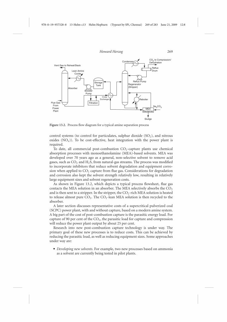
Figure 13.2. Process flow diagram for a typical amine separation process
control systems (to control for particulates, sulphur dioxide (SO2), and nitrousoxides (NOx)). To be cost-effective, heat integration with the power plant isrequired.
To date, all commercial post-combustion CO2-capture plants use chemicalabsorption processes with monoethanolamine (MEA)-based solvents. MEA wasdeveloped over 70 years ago as a general, non-selective solvent to remove acidgases, such as CO2 and H2S, from natural-gas streams. The process was modifiedto incorporate inhibitors that reduce solvent degradation and equipment corro-sion when applied to CO2 capture from flue gas. Considerations for degradationand corrosion also kept the solvent strength relatively low, resulting in relativelylarge equipment sizes and solvent regeneration costs.
As shown in Figure 13.2, which depicts a typical process flowsheet, flue gascontacts the MEA solution in an absorber. The MEA selectively absorbs the CO2
and is then sent to a stripper. In the stripper, the CO2-rich MEA solution is heatedto release almost pure CO2. The CO2-lean MEA solution is then recycled to theabsorber.
A later section discusses representative costs of a supercritical pulverized coal(SCPC) power plant, with and without capture, based on a modern amine system.A big part of the cost of post-combustion capture is the parasitic energy load. Forcapture of 90 per cent of the CO2, the parasitic load for capture and compressionwill reduce the power plant output by about 25 per cent.
Research into new post-combustion capture technology is under way. Theprimary goal of these new processes is to reduce costs. This can be achieved byreducing the parasitic load, as well as reducing equipment sizes. Some approachesunder way are:
� Developing new solvents. For example, two new processes based on ammoniaas a solvent are currently being tested in pilot plants.
978–0–19–957328–8 13-Helm-c13 Helm Hepburn (Typeset by SPi, Chennai) 270 of 283 June 21, 2009 12:8
270 Carbon Dioxide Capture and Storage
� Using alternative separation processes. These include adsorption andmembrane-based processes. While theoretically possible, it is a difficult taskdue to the low CO2 concentrations and pressures in the flue gas.
� Developing new separation materials. This is a new line of research that is stillin the early stages of development. However, materials such as ionic liquidsor metal organic frameworks (MOFs) are being applied to the CO2-captureproblem. They offer the possibility of significant cost reductions but notenough research has been carried out yet to judge whether they can be appliedat the required scale and in the harsh flue-gas environment.
(ii) Oxy-Combustion Capture
Because nitrogen is the major component of flue gas in power plants that burn coalin air (which nearly all existing plants do), post-combustion capture is essentially anitrogen–carbon dioxide separation. If there were no nitrogen, CO2 capture fromflue gas would be greatly simplified. This is the thinking behind oxy-combustioncapture: instead of air, the power plant is fed oxygen that is produced on site in anair separation plant. The resulting flue gas will be mostly CO2 and H2O, which areeasily separable (the water condenses out in the compression process).
A few items about this process should be noted.
� The primary separation process has now shifted from the flue gas to the intakeair, where oxygen is separated from nitrogen. This is done in a standard airseparation unit (ASU), but it will have a large parasitic load of about 15per cent of a power plant’s electric output.
� A standard power boiler can be used for this process (making retrofits of thistechnology to standard PC plants possible), but a portion of the flue gas needsto be recycled into the combustion chamber in order to control the flametemperature.
� Once the water is separated out, the flue gas will be over 90 per cent CO2.However, there will be minor impurities in the effluent, including SO2, NOx,and non-condensables such as oxygen and nitrogen. In general, these impu-rities will need to be cleaned up before the CO2 is ready for transport andinjection.
Studies show that oxy-combustion capture can be competitive with post-combustion capture. However, experience with oxy-combustion is limited. InSeptember 2008, Vattenfall began operation of a 30 megawatt thermal (MWth)oxy-combustion pilot plant at its Schwarze Pumpe site in Germany. The costof this facility was about $100m and it is expected to provide critical operat-ing data for the oxy-combustion process. Vattenfall projects that for full-scaleoperations, the cost of oxy-combustion capture will be 40 euros/tonne CO2 orless.
978–0–19–957328–8 13-Helm-c13 Helm Hepburn (Typeset by SPi, Chennai) 271 of 283 June 21, 2009 12:8
Howard Herzog 271
Future improvements in oxy-combustion can come from:
� specially designed boilers that increase efficiency and eliminate the need forthe external recycle of flue gas;
� use of ionic transport membranes for oxygen production.
Other oxy-combustion technologies are:
� Chemical looping combustion, where solids flow between two fluidized bedreactors. In one reactor, the solid reacts with air (picking up oxygen). In thesecond reactor, it reacts with fuel (losing its oxygen). If successful, this processcan essentially eliminate the cost of oxygen production.
� Clean Energy Systems has a process based on an ‘oxygen turbine’ (as opposedto oxygen boilers in the systems above). A pilot plant is currently underconstruction in California as part of the US Regional Partnership Program.
(iii) Pre-Combustion Capture
Pre-combustion capture is usually applied in IGCC power plants. This processincludes gasifying the coal to produce a synthesis gas composed of carbonmonoxide (CO) and hydrogen (H2); reacting the CO with water (in a water-gasshift reaction) to produce CO2 and H2; capturing the CO2; and sending the H2 toa turbine to produce electricity. Since the primary fuel sent to the gas turbine isnow hydrogen, some can be bled off as a fuel for separate use, such as in hydrogenfuel cells to be used in transportation vehicles.
Capturing CO2 before combustion offers some advantages. First, CO2 is notyet diluted by the combustion air. Second, the CO2-containing stream is usu-ally at elevated pressure. Therefore, more efficient separation methods can beapplied, for example using pressure-swing-absorption in physical solvents, suchas methanol or polyethylene glycol (commercial brands are Rectisol and Selexol).One of the biggest barriers to this pathway is that currently electricity generationis cheaper in PC power plants than in IGCC plants. The pre-combustion processcould also be used when natural gas is the primary fuel. Here, a synthesis gas isformed by reacting natural gas with steam to produce CO2 and H2. However, forthe natural gas case, it is unproven whether pre-combustion capture is preferableto the standard post-combustion capture.
Worldwide, gasification facilities exist today that do not produce electricity, butsynthesis gas and various other byproducts of coal gasification. In these facilities,CO2 is separated after the gasification stage from the other gases, such as methane,hydrogen, or a mix of CO and hydrogen. The synthesis gas or hydrogen is usedas a fuel or as a chemical raw material, e.g. for liquid fuel manufacturing orammonia synthesis. The CO2 can also be used as a chemical raw material, for dry-ice manufacturing, carbonated beverages, and EOR. For example, the Great PlainsSynfuel Plant, near Beulah, North Dakota, gasifies 16,326 tonnes per day of lignite
978–0–19–957328–8 13-Helm-c13 Helm Hepburn (Typeset by SPi, Chennai) 272 of 283 June 21, 2009 12:8
272 Carbon Dioxide Capture and Storage
coal into 3.5m standard cubic metres per day of combustible syngas, and close to7m standard cubic metres of CO2. A part of the CO2 is captured by a physicalsolvent based on methanol. The captured CO2 is compressed and 2.7 m millionstandard cubic metres per day are piped over a 325 km distance to the Weyburn,Saskatchewan, oil field, where the CO2 is used for enhanced oil recovery.
V. GEOLOGICAL STORAGE
(i) Types of Formations
Geological sinks for CO2 include oil and gas reservoirs, deep saline formations,and unminable coal seams. Together, these can hold hundreds to thousands ofgigatons of carbon (GtC), and the technology to inject CO2 into the ground iswell established. CO2 is stored in geologic formations by a number of differenttrapping mechanisms that depend on the formation type.
Oil and Gas Reservoirs
Depleted oil and gas reservoirs have proven that they can hold hydrocarbons formillions of years. This gives confidence that they can store CO2 for a long time.Also, these reservoirs are relatively well characterized. However, some questionsarise about whether the wells drilled into the reservoirs and the removal of thehydrocarbons have compromised their integrity. Active oil reservoirs have becomea high priority target, since CO2 storage can be combined with EOR.
Unmineable Coal Seams
Abandoned or uneconomic coal seams are another potential storage site. CO2
diffuses through the pore structure of coal and is physically adsorbed to it. Thisprocess is similar to the way in which activated carbon removes impurities fromair or water. The exposed coal surface has a preferential affinity for adsorption ofCO2 than for methane with a ratio of 2:1.
Deep Saline Formations
Deep saline formations, both subterranean and sub-seabed, may have the greatestCO2 storage potential. These reservoirs are the most widespread and have thelargest volumes. The density of CO2 depends on the depth of injection, whichdetermines the ambient temperature and pressure. The CO2 must be injectedbelow 800 metres so that it is in a dense phase (either liquid or supercritical).When injected at these depths, the specific gravity of CO2 ranges from 0.5 to 0.9,which is lower than that of the ambient aquifer brine. Therefore, CO2 is buoyantand will naturally try to rise to the top of the reservoir.
978–0–19–957328–8 13-Helm-c13 Helm Hepburn (Typeset by SPi, Chennai) 273 of 283 June 21, 2009 12:8
Howard Herzog 273
Time since injection stops (years)
Structural &stratigraphic
trapping
Residual CO2trapping
Increasing Storage Security
Solubilitytrapping
Mineraltrapping
100
10
10 100 1,000 10,000
% T
rap
pin
g c
on
trib
uti
on
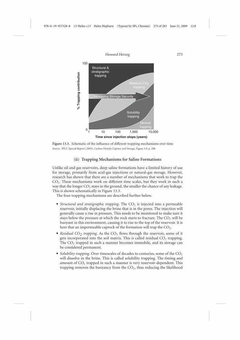
Figure 13.3. Schematic of the influence of different trapping mechanisms over timeSource: IPCC Special Report (2005), Carbon Dioxide Capture and Storage, Figure 5.9, p. 208.
(ii) Trapping Mechanisms for Saline Formations
Unlike oil and gas reservoirs, deep saline formations have a limited history of usefor storage, primarily from acid-gas injections or natural-gas storage. However,research has shown that there are a number of mechanisms that work to trap theCO2. These mechanisms work on different time scales, but they work in such away that the longer CO2 stays in the ground, the smaller the chance of any leakage.This is shown schematically in Figure 13.3.
The four trapping mechanisms are described further below.
� Structural and stratigraphic trapping. The CO2 is injected into a permeablereservoir, initially displacing the brine that is in the pores. The injection willgenerally cause a rise in pressure. This needs to be monitored to make sure itstays below the pressure at which the rock starts to fracture. The CO2 will bebuoyant in this environment, causing it to rise to the top of the reservoir. It ishere that an impermeable caprock of the formation will trap the CO2.
� Residual CO2 trapping. As the CO2 flows through the reservoir, some of itgets incorporated into the soil matrix. This is called residual CO2 trapping.The CO2 trapped in such a manner becomes immobile, and its storage canbe considered permanent.
� Solubility trapping. Over timescales of decades to centuries, some of the CO2
will dissolve in the brine. This is called solubility trapping. The timing andamount of CO2 trapped in such a manner is very reservoir-dependent. Thistrapping removes the buoyancy from the CO2, thus reducing the likelihood
978–0–19–957328–8 13-Helm-c13 Helm Hepburn (Typeset by SPi, Chennai) 274 of 283 June 21, 2009 12:8
274 Carbon Dioxide Capture and Storage
of leakage. If the brine ever leaves the reservoir, the CO2 will be released.However, this usually occurs on very long timescales.
� Mineral trapping. Over centuries to millennia, the injected CO2 may reactwith the minerals in the reservoir. Essentially, CO2 can get incorporated intothe solid rocks and minerals in the reservoir. This is called mineral trappingand can be considered permanent storage.
(iii) Capacity
The IPCC Special Report, Carbon Dioxide Capture and Storage, concluded that‘available evidence suggests that, it is likely that there is a technical potential ofat least about 2,000 GtCO2 of storage capacity in geological formations’. This is alarge number (about two orders of magnitude greater than total annual worldwideCO2 emissions), indicating the potential of CCS to be a significant CO2 mitigationstrategy. It should be pointed out that some countries have an abundance ofstorage capacity (e.g. USA, Australia), while others have limited options (e.g.Japan).
The reservoirs with the largest potential capacity are the deep saline formations.At present, capacity estimates for CO2 storage in deep saline formations are highlyuncertain. This is because the data required to do rigorous capacity calculationsare very sparse. Data are typically obtained through drilling wells. Unlike oil andgas reservoirs, deep saline formations have no commercial value, so the numberof wells drilled into these formations is limited.
On the other hand, much more data exist for storage estimates in oil and gasreservoirs. However, owing to a current lack of field data needed to confirm themethodology used to calculate storage capacities, there is still uncertainty in thesenumbers.
Calculating storage capacities in coal seams is very difficult, in part because thefeasibility of large-scale storage in coal seams has not been demonstrated. Anycapacity estimates for these formations must be taken as very highly uncertain.
The US Department of Energy (DOE) has just completed a Carbon Seques-tration Atlas of the United States and Canada.5 It gives capacity estimates for oiland gas reservoirs as 82 GtCO2. For saline formations, it gives a range of 920–3,400 GtCO2. The high end of this range is greater than the worldwide capacityreported by the IPCC. It should be noted that the IPCC was being conservative inits estimates (saying ‘at least’), but this does highlight the uncertainty in makingthese estimates.
In summary:
� At present, capacity estimates are highly uncertain;� however, there is a broad consensus that the capacity will be large enough for
CCS to be a significant CO2 mitigation strategy;
5 Available at http://www.netl.doe.gov/technologies/carbon_seq/refshelf/atlas/
978–0–19–957328–8 13-Helm-c13 Helm Hepburn (Typeset by SPi, Chennai) 275 of 283 June 21, 2009 12:8
Howard Herzog 275
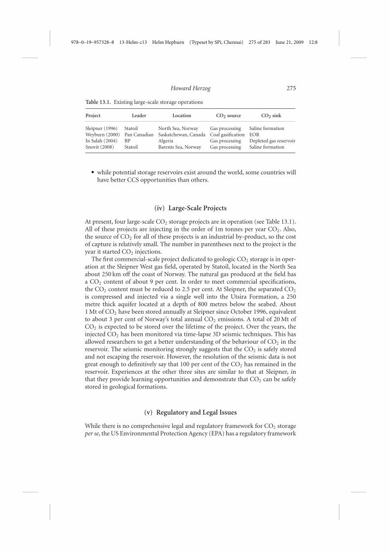
Table 13.1. Existing large-scale storage operations
Project Leader Location CO2 source CO2 sink
Sleipner (1996) Statoil North Sea, Norway Gas processing Saline formationWeyburn (2000) Pan Canadian Saskatchewan, Canada Coal gasification EORIn Salah (2004) BP Algeria Gas processing Depleted gas reservoirSnovit (2008) Statoil Barents Sea, Norway Gas processing Saline formation
� while potential storage reservoirs exist around the world, some countries willhave better CCS opportunities than others.
(iv) Large-Scale Projects
At present, four large-scale CO2 storage projects are in operation (see Table 13.1).All of these projects are injecting in the order of 1m tonnes per year CO2. Also,the source of CO2 for all of these projects is an industrial by-product, so the costof capture is relatively small. The number in parentheses next to the project is theyear it started CO2 injections.
The first commercial-scale project dedicated to geologic CO2 storage is in oper-ation at the Sleipner West gas field, operated by Statoil, located in the North Seaabout 250 km off the coast of Norway. The natural gas produced at the field hasa CO2 content of about 9 per cent. In order to meet commercial specifications,the CO2 content must be reduced to 2.5 per cent. At Sleipner, the separated CO2
is compressed and injected via a single well into the Utsira Formation, a 250metre thick aquifer located at a depth of 800 metres below the seabed. About1 Mt of CO2 have been stored annually at Sleipner since October 1996, equivalentto about 3 per cent of Norway’s total annual CO2 emissions. A total of 20 Mt ofCO2 is expected to be stored over the lifetime of the project. Over the years, theinjected CO2 has been monitored via time-lapse 3D seismic techniques. This hasallowed researchers to get a better understanding of the behaviour of CO2 in thereservoir. The seismic monitoring strongly suggests that the CO2 is safely storedand not escaping the reservoir. However, the resolution of the seismic data is notgreat enough to definitively say that 100 per cent of the CO2 has remained in thereservoir. Experiences at the other three sites are similar to that at Sleipner, inthat they provide learning opportunities and demonstrate that CO2 can be safelystored in geological formations.
(v) Regulatory and Legal Issues
While there is no comprehensive legal and regulatory framework for CO2 storageper se, the US Environmental Protection Agency (EPA) has a regulatory framework

978–0–19–957328–8 13-Helm-c13 Helm Hepburn (Typeset by SPi, Chennai) 276 of 283 June 21, 2009 12:8
276 Carbon Dioxide Capture and Storage
governing most types of underground injection, the Underground Injection Con-trol (UIC) Program. The UIC Program was created under the Safe Drinking WaterAct of 1974 (SDWA) and establishes requirements to assure that undergroundinjection activities will not endanger drinking-water sources. The UIC Programregulates underground injection under five different classes of injection wells,depending on the type of fluid being injected, the purpose of injection, and thesubsurface location where the fluid is to remain. States are allowed to assumeprimary responsibility for implementing the UIC requirements in their borders aslong as the state programme is consistent with EPA regulations and has receivedEPA approval. Injection operators are required to provide financial assurance incase they cease operations, with the level of assurance a function of the estimatedcost of plugging and abandoning the injection well.
Recently, the EPA released a proposed rule for federal requirements under theUIC Program for CO2 geologic sequestration (GS) wells.6 Below is an excerptfrom the EPA’s fact sheet7 on the new rules.
EPA’s proposed rule would establish a new class of injection well—Class VI—and technicalcriteria for geologic site characterization; area of review and corrective action; well con-struction and operation; mechanical integrity testing and monitoring; well plugging; post-injection site care; and site closure for the purposes of protecting underground sources ofdrinking water.
The elements of today’s proposal build upon the existing UIC regulatory framework,with modifications based on the unique nature of CO2 injection for GS, including:
� Geologic site characterization to ensure that GS wells are appropriately sited;� Requirements to construct wells with injectate-compatible materials and in a manner
that prevents fluid movement into unintended zones;� Periodic re-evaluation of the area of review around the injection well to incorporate
monitoring and operational data and verify that the CO2 is moving as predictedwithin the subsurface;
� Testing of the mechanical integrity of the injection well, ground water monitoring,and tracking of the location of the injected CO2 to ensure protection of undergroundsources of drinking water;
� Extended post-injection monitoring and site care to track the location of the injectedCO2 and monitor subsurface pressures; and
� Financial responsibility requirements to assure that funds will be available for wellplugging, site care, closure, and emergency and remedial response.
Beyond incorporation into existing regulations, CCS contains some items that gobeyond the scope of the UIC Program. One item is legal access to the geologicformation. In most of the world, the pore space is owned by the state, so this is nota major problem. However, in the United States, this is not the case. While theremay be some differences between the states, people that own mineral rights and/or
6 See http://www.epa.gov/safewater/uic/wells_sequestration.html7 See http://www.epa.gov/safewater/uic/pdfs/fs_uic_co2_proposedrule.pdf
978–0–19–957328–8 13-Helm-c13 Helm Hepburn (Typeset by SPi, Chennai) 277 of 283 June 21, 2009 12:8
Howard Herzog 277
surface rights will have claim to ownership of the pore space. Under current law,the right to use the sub-surface would need to be acquired from every owner wherethe CO2 plume migrates. This could become impractical in many situations, sonew legislation may be needed to ease this process.
How to deal with the long-term stewardship and liability of the CO2 is still anopen issue. By long term, we mean centuries or longer. Questions on how to mon-itor the reservoir once it is closed and for how long need to be resolved. Liabilitywould arise if CO2 leaked out and caused environmental or health problems, butit is a highly unlikely that leaking CO2 is a significant health or environmentalrisk. Of more concern, a leaking CO2 reservoir becomes a CO2 emissions source.We assume that there will be a charge for CO2 emissions (through either a tax orcap-and-trade system), and someone would be liable for that charge. It has beensuggested that a number of years after closure (in the order of 10 years) and assum-ing no significant leakage or operational problems, the long-term stewardship andliability would be taken over by the government. To help pay for this, companiesinjecting CO2 into the ground would pay into a liability fund.
VI. COSTS8
In MIT’s The Future of Coal report (MIT, 2007), detailed cost estimates weredeveloped for all three of the CO2-capture categories discussed in section IV. How-ever, in the report, costs were based on analyses done in the 2000–4 timeframe,with costs given in 2005 US dollars. Since then, commodity and fuel costs haverisen significantly, resulting in significant increases in costs. For example, CERA(Cambridge Energy Research Associates) reports that capital costs for coal-firedpower plants have risen about 80 per cent over this timeframe.
Recently, we updated the cost estimates from The Future of Coal study. Weonly published the costs for supercritical pulverized coal (SCPC), since the recentliterature and discussion with industry experts support these new estimates. Wedecided not to publish new cost estimates for IGCC and oxy-fuel combustiontechnology for two reasons. The first reason is the tremendous uncertainty regard-ing the true costs and performance characteristics of such new technologies. Thesecond reason is that our discussion with industry experts indicates that anycurrent IGCC cost estimate is highly uncertain since costs for IGCC may havedoubled or tripled since 2004. To present a new estimate under such high uncer-tainty would be detrimental to the discussion about new-generation technology.This situation underscores the importance for new comprehensive design and coststudies reflecting the new technical knowledge about IGCC in this transient costenvironment.
8 This section is based on Hamilton et al. (2008). See http://sequestration.mit.edu/pdf/GHGT9_Hamilton_Herzog_Parsons.pdf for more details.
978–0–19–957328–8 13-Helm-c13 Helm Hepburn (Typeset by SPi, Chennai) 278 of 283 June 21, 2009 12:8
278 Carbon Dioxide Capture and Storage
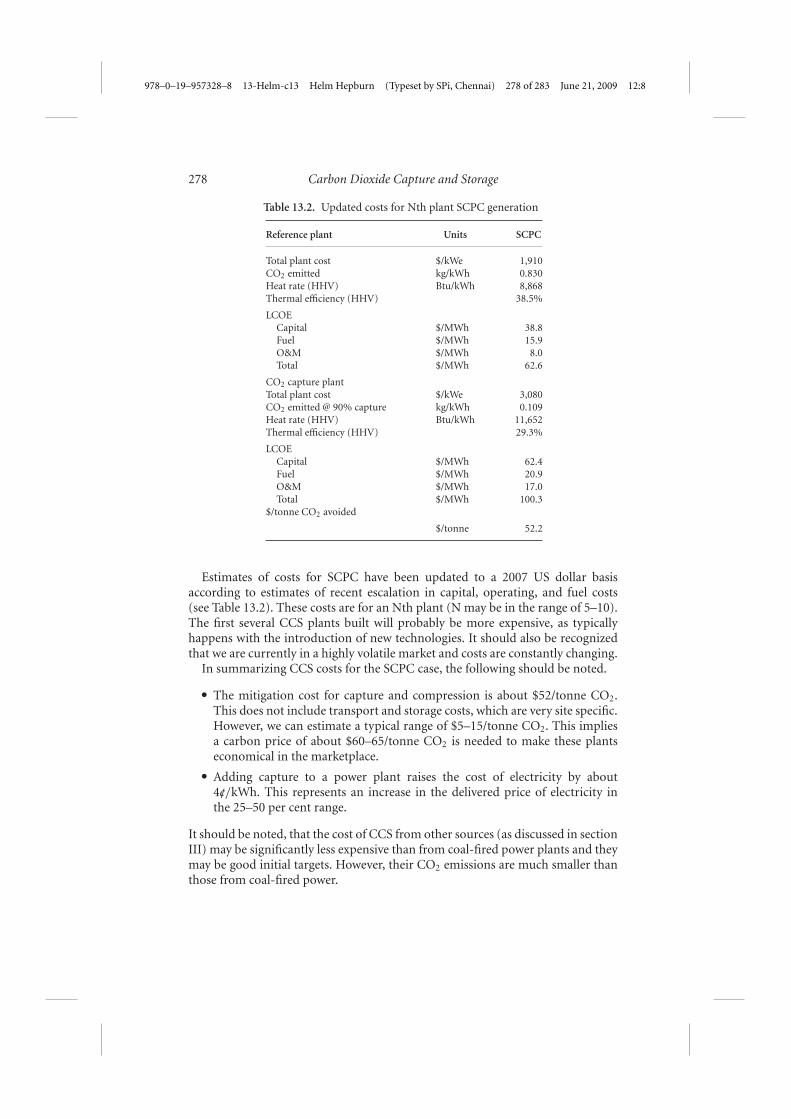
Table 13.2. Updated costs for Nth plant SCPC generation
Reference plant Units SCPC
Total plant cost $/kWe 1,910CO2 emitted kg/kWh 0.830Heat rate (HHV) Btu/kWh 8,868Thermal efficiency (HHV) 38.5%
LCOECapital $/MWh 38.8Fuel $/MWh 15.9O&M $/MWh 8.0Total $/MWh 62.6
CO2 capture plantTotal plant cost $/kWe 3,080CO2 emitted @ 90% capture kg/kWh 0.109Heat rate (HHV) Btu/kWh 11,652Thermal efficiency (HHV) 29.3%
LCOECapital $/MWh 62.4Fuel $/MWh 20.9O&M $/MWh 17.0Total $/MWh 100.3
$/tonne CO2 avoided
$/tonne 52.2
Estimates of costs for SCPC have been updated to a 2007 US dollar basisaccording to estimates of recent escalation in capital, operating, and fuel costs(see Table 13.2). These costs are for an Nth plant (N may be in the range of 5–10).The first several CCS plants built will probably be more expensive, as typicallyhappens with the introduction of new technologies. It should also be recognizedthat we are currently in a highly volatile market and costs are constantly changing.
In summarizing CCS costs for the SCPC case, the following should be noted.
� The mitigation cost for capture and compression is about $52/tonne CO2.This does not include transport and storage costs, which are very site specific.However, we can estimate a typical range of $5–15/tonne CO2. This impliesa carbon price of about $60–65/tonne CO2 is needed to make these plantseconomical in the marketplace.
� Adding capture to a power plant raises the cost of electricity by about4c//kWh. This represents an increase in the delivered price of electricity inthe 25–50 per cent range.
It should be noted, that the cost of CCS from other sources (as discussed in sectionIII) may be significantly less expensive than from coal-fired power plants and theymay be good initial targets. However, their CO2 emissions are much smaller thanthose from coal-fired power.

978–0–19–957328–8 13-Helm-c13 Helm Hepburn (Typeset by SPi, Chennai) 279 of 283 June 21, 2009 12:8
Howard Herzog 279
VII. CHINA
China has abundant coal reserves. Inexpensive coal has been crucial in poweringChina’s rapid growth; on average, a new coal plant starts up every week in China.Since this trend is likely to continue (at perhaps a reduced rate), the question ofwhether CCS can be deployed in China is important.
Some specific points can be made about China and CCS.
� The CCS technology used in China will be essentially the same as is used inthe USA and Europe.
� No authoritative studies have been conducted on potential geologic storagereservoirs in China. However, initial assessments suggest that, while not asabundant as in, say, the United States, there are significant resources available.
� China has shown a willingness to host CCS demonstration projects. Chinaseems to have an easier time in developing infrastructure than the USA orEurope.
CCS, like most mitigation technologies, is very dependent on what China decidesto do about climate policy in general. The MIT coal study (MIT, 2007) looked atChina and concluded that it will probably lag the West in adoption of climatepolicies. How to integrate China and the rest of the developing world into aninternational climate regime is a difficult and critical issue, but beyond the scopeof this paper.
The cost of CCS may also significantly slow its adoption by China, even afterChina implements a climate policy. Therefore, reducing costs for CCS becomeseven more important in the China context.
VIII. THE POLICY CONTEXT AND THE FUTURE OF CCS
There are many roads CCS can take as we move forward. What path it takesdepends not only on how the technology evolves, but also on how climate-changetechnology evolves. In this concluding section, CCS is discussed in this policycontext.
First, it may be instructive to look at example scenarios for the growth of CCS.MIT (2007) presented simulations performed with its emissions predictions pol-icy analysis (EPPA) model, a computable general equilibrium (CGE) model of theworld economy. One set of simulations in the report contrast a business-as-usual(BAU) scenario, with two policy cases, one with a high global carbon price andone with a low price, implemented either through cap-and-trade or a carbon tax.The low carbon price is modelled as beginning in 2010 at $7/ton CO2, increasingat a real rate of 5 per cent annually, and the high carbon price begins at $25/tonCO2 in 2015, increasing at an annual rate of 4 per cent thereafter. Table 13.3 fromthe report shows the resulting coal CO2 emissions, the coal consumption, and

978–0–19–957328–8 13-Helm-c13 Helm Hepburn (Typeset by SPi, Chennai) 280 of 283 June 21, 2009 12:8
280 Carbon Dioxide Capture and Storage
Table 13.3. Implications for global coal consumption under alternative CO2
price assumptions (from MIT, 2007)
2000 BAU2050
Low CO2
price 2050High CO2
price 2050
Coal CO2 emissions (GtCO2/year) 9 32 15 5Coal consumption (Exajoules (EJ)/year) 100 448 200 161% Coal with CCS 0 0 4 60
the proportion of coal technologies that use CCS under the three scenarios. Thesimulations assume limited expansion of nuclear technologies and a reference gasprice with no breakthroughs in liquefied natural gas (LNG) transport.
The model predicts that, under the BAU scenario, global CO2 emissions fromcoal will reach 32GtCO2/year by 2050. Under both CO2 price scenarios, coal usegrows from current levels, but not as much as under the BAU case. However,thanks to CCS, under a high CO2 price, coal consumption still grows by over 60per cent, but its emissions are almost cut in half.
The above simulation assumes that CCS has achieved both technological readi-ness and that policies are in place to create a market for CCS. Today, neither ofthese assumptions is valid. Below is an outline of the actions and policies necessaryfor CCS to move forward.
In the MIT study (MIT, 2007), conducting large-scale CCS demonstrations wasidentified as the key to achieving technological readiness:
The central message of our study is that demonstration of technical, economic, and insti-tutional features of carbon capture and sequestration at commercial scale coal combustionand conversion plants, will (1) give policymakers and the public confidence that a practicalcarbon mitigation control option exists, (2) shorten the deployment time and reduce thecost for carbon capture and sequestration should a carbon emission control policy beadopted, and (3) maintain opportunities for the lowest cost and most widely availableenergy form to be used to meet the world’s pressing energy needs in an environmentallyacceptable manner.
MIT called for 3–5 demonstration projects in the US in the next 8–10 years. Morerecently, at their 2008 meeting in Japan, the G-8 called for 20 demonstrationsworldwide by 2020. The demonstration projects, coupled with a strong R&Dprogramme, would help address the two biggest challenges for CCS:
� reducing or eliminating first-mover costs;� reducing uncertainties primarily associated with storage at scale:� capacity� long-term integrity� regulatory framework� liability� public acceptance.
978–0–19–957328–8 13-Helm-c13 Helm Hepburn (Typeset by SPi, Chennai) 281 of 283 June 21, 2009 12:8
Howard Herzog 281
Assuming a successful demonstration programme, by 2020 CCS could be readyfor large-scale deployment. However, an additional three key ingredients are nec-essary for CCS to be considered truly commercial.
(i) Creating a market through climate policyAs stated in section VI, a carbon price of about $60–65/tonne CO2 isneeded to make CCS from power production economical in the mar-ketplace. While a cap-and-trade system (or carbon tax) can create a car-bon price, it is highly unlikely that climate policy will result in a carbonprice greater than $60/tonne CO2 by 2020. Therefore, there will be agap between the cost of CCS and the carbon price. Over time, the car-bon price will rise and the cost of CCS may fall, giving hope that thegap will eventually disappear. However, for a decade or two, additionalpolicy measures will be needed to promote CCS. These can take manyforms—direct subsidies, production credits, bonus allowances, portfoliostandards, etc.
(ii) Providing a regulatory environmentCompanies will not enter a business with a high degree of regulatoryuncertainty. As discussed in section V, there are three primary concernsthat must be addressed:� ownership of the pore space;� regulations for site selection, injection operations, and site closure;� resolution of the long-term liability issue.
(iii) Development of a business structureWhile the two items above are primarily government tasks, this item is upto the private sector. It is the private sector that will build and operate CCSsystems. It is the private sector that will make choices about technologyand will spur future improvements. It is highly unlikely that one companywill offer services for all parts of the CCS value chain. Today, quite afew companies are actively working to provide capture technology. Also,CO2 transport companies exist. However, no companies exist to providestorage services or long-term stewardship. In addition, rules for how thesecompanies interact still need to be developed.
IX. CONCLUSIONS
To summarize some of the key messages from this paper:
� there is a growing consensus that it will be impossible to achieve significantcuts in greenhouse-gas emissions (50–80 per cent below today’s levels) with-out CCS. So while CCS may not be a silver bullet, it can be considered a‘keystone’ technology;

978–0–19–957328–8 13-Helm-c13 Helm Hepburn (Typeset by SPi, Chennai) 282 of 283 June 21, 2009 12:8
282 Carbon Dioxide Capture and Storage
� all components of a CCS system are commercially available and in operationtoday;
� the key technical challenge for CCS is the integration and scaling-up ofthe system components. This is a significant task that relies on majorinvestments in the technology, but no technological breakthroughs arerequired.
The steps moving CCS to commercialization rely on making the necessary invest-ments in the technology and involve both the private and public sectors. The fouressential elements include:
� private–public partnerships are needed to build and operate approximatelyten demonstration plants worldwide over the next decade;
� governments (with advice from the private sector) must create a market forCCS through climate policy. The policy should be technologically-neutral(i.e. avoid picking winners and losers);
� governments (with advice from the private sector) must provide a suitableregulatory environment for CCS. These regulations must be stringent enoughto protect the public interests, but not overly stringent so as to stifle CCSdevelopment;
� the private sector must develop a business organization to address all com-ponents of the CCS value chain. The implementation of CCS, includingdecisions on the appropriate technologies, needs to be left up to the privatesector.
BACKGROUND READING
Most of the material in this paper has been based on publications produced bythe MIT Carbon Capture and Sequestration Program. These publications can befound at http://sequestration.mit.edu/Several publications in particular were heavily relied upon:
de Figueiredo, M.A., Herzog, H. J., Joskow, P. L., Oye, K. A., and Reiner, D. M. (2007),‘Regulating Carbon Dioxide Capture and Storage’, CEEPR WP-2007-003, April.
Hamilton, M., Herzog, H. J., and Parsons, J. (2008), ‘Cost and US Public Policy forNew Coal Power Plants with Carbon Capture and Sequestration’, presented at the 9thInternational Conference on Greenhouse Gas Control Technologies, Washington, DC,November.
Herzog, H. J., and Golomb, D. (2004), ‘Carbon Capture and Storage from Fossil FuelUse’, in C. J. Cleveland (ed.), Encyclopedia of Energy, New York, Elsevier Science,277–87.
MIT (2007), The Future of Coal: Options for a Carbon Constrained World, MassachusettsInstitute of Technology, available at http://mit.edu/coal/

978–0–19–957328–8 13-Helm-c13 Helm Hepburn (Typeset by SPi, Chennai) 283 of 283 June 21, 2009 12:8
Howard Herzog 283
In addition, two sources of additional reading are recommended for those whowant to explore more deeply some of the topics discussed in this paper:
IPCC (2005), Carbon Dioxide Capture and Storage, Intergovernmental Panel on Cli-mate Change, Special Report, New York, Cambridge University Press, available athttp://www.ipcc.ch/ipccreports/srccs.htm
Proceedings of the 9th International Conference on Greenhouse Gas Control Technologies,Washington, DC, November 2008 (forthcoming). This will be made available throughScience Direct in February 2009.