Embed Size (px)
Citation preview
13
Demisting Cyclones
Until now we have been concerned with the separation of solid particles fromgas streams. However, cyclones may be also utilized quite effectively to sepa-rate liquids contained in a carrier gas stream. The principles are the same butliquids pose some unique problems and some advantages relative to solids-collecting cyclones.
We wish to point out at the outset here that, by far, the majority ofvapor-liquid separation tasks are performed using either conventional gravitysettling or ‘knock-out’ drums or demisting meshes or pads. Knock-out drumsor pots are very robust and are almost always used to separate liquid fromcarrier gas stream if the incoming stream contains a high volumetric fraction ofliquid (greater than several percent). With proper design they can generallybe depended upon to separate the majority of droplets greater than about500 µm but are not suitable for collecting finer droplets. Demisting mats, onthe other hand, exhibit relatively low pressure drops (typically less than afew centimeters of water column) and can capture drops as small as a fewmicrons. They are not suitable for high liquid loading conditions such as thatwhich may exists under two-phase slug flow conditions, nor in applicationswhere the demisting mat could be exposed to foam. They are also subject tofouling from any solids or waxy, gummy or coke-forming material in the feedstream.
In between these two separator types are vapor-liquid cyclone separators.Cyclonic type separators have been gaining in importance during the pastdecade and are now playing a major role in the oil and gas industries, especiallyin offshore applications where large and expensive gravity separators are beingreplaced by much more compact, and much more efficient gas-liquid separationequipment. In gas transmission installations cyclones are also well suited toprotect gas compressors and turbines from fouling and erosion. In such servicethey are capable of removing essentially 100% of the solid and liquid particles6 to 8 microns and larger.
Cyclones, like gravity separators, can be designed to handle large volu-metric concentrations of incoming liquid if they are equipped with or set atop
288 13 Demisting Cyclones
a liquid hold-up drum. As with a gravity separator, such a drum is used toprovide liquid level control and, normally, several minutes of liquid surge ca-pacity. Our focus, herein, however, will be on what we shall call ‘demisting’cyclones.
Unlike the particles feeding conventional gas-solids cyclones, liquid par-ticles feeding a gas-liquid cyclone are normally greater in size and are notporous. These two factors tend to make for an easier separation. In many sys-tems the gas/liquid mixture feeding the cyclone enters through some upstreampiping wherein small droplets coalesce into larger drops, the driving force forthe coalescence of colliding droplets being provided by surface tension. We’llpresent an example of this below. In addition, unlike gas-solids cyclones, oncethe incoming liquid droplets are centrifuged to the wall of the cyclone, theymerge with the liquid wall film to form a much larger mass which is not easilyremoved or re-entrained back into the gas phase. In gas-solids cyclones, finedust particles are much more easily re-entrained off the walls. The droplets en-tering a gas-liquid cyclone are also not likely to plug the cyclone as sometimesoccurs with statically charged or tacky solids in a gas-solids cyclone.
In some applications, deposits may form on the roof or outside area ofthe vortex tube if these surfaces are not sufficiently wetted by the incomingliquid. In these cases, the affected surfaces normally can be kept clean withspray nozzles. Gas-liquid cyclones do not normally pose the same erosion con-cerns experienced with certain solids handling cyclones. The factors mentionedabove – the formation of wall films and their relative immunity to both plug-ging and erosion – have given their designers more latitude with respect totheir construction and design details than that commonly observed with gas-solids cyclones. Thus, demisting cyclones can be found with a wide variety ofinternal features including relatively thin, close-fitting vanes, narrow slits orshave-offs, anti-creep skirts, isolation disks, coalescing mats, relatively smallliquid discharge openings, recirculation slots or slits and attendant piping,and other intricate internals.
13.1 Liquid Creep and ‘Layer Loss’
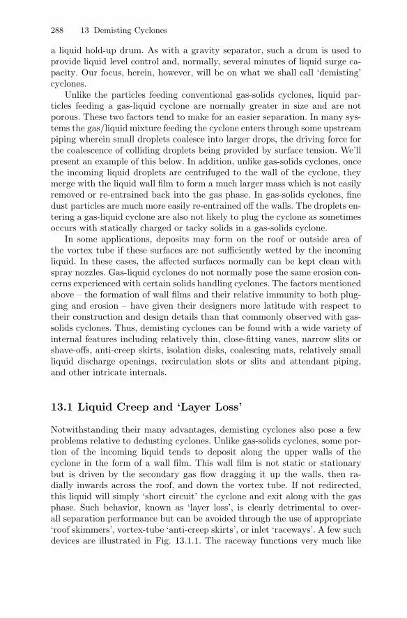
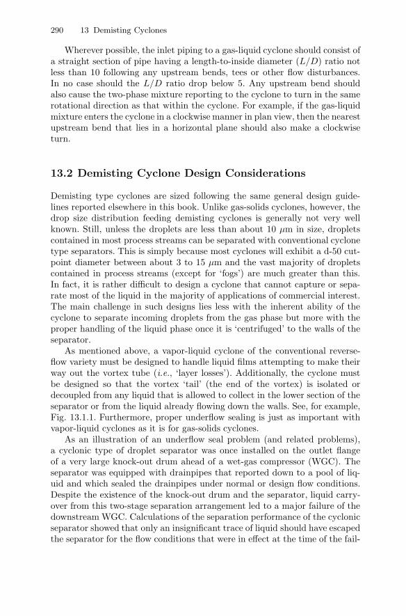
Notwithstanding their many advantages, demisting cyclones also pose a fewproblems relative to dedusting cyclones. Unlike gas-solids cyclones, some por-tion of the incoming liquid tends to deposit along the upper walls of thecyclone in the form of a wall film. This wall film is not static or stationarybut is driven by the secondary gas flow dragging it up the walls, then ra-dially inwards across the roof, and down the vortex tube. If not redirected,this liquid will simply ‘short circuit’ the cyclone and exit along with the gasphase. Such behavior, known as ‘layer loss’, is clearly detrimental to over-all separation performance but can be avoided through the use of appropriate‘roof skimmers’, vortex-tube ‘anti-creep skirts’, or inlet ‘raceways’. A few suchdevices are illustrated in Fig. 13.1.1. The raceway functions very much like
13.1 Liquid Creep and ‘Layer Loss’ 289
the roof-skimming cylinder but attempts to prevent liquid from reaching theupper areas of the cyclone in the first place. The anti-creep skirt often has aserrated or ‘saw-toothed’ trailing edge to facilitate the dislodging of the liquidfilm. At high liquid loadings (greater than about 1 kg liquid/kg of gas), bothroof skimmer or raceway and an anti-creep skirt should be installed.
Roof Skimmer Cylinder
Vortex Tube
Isolation Plate
Vortex Breaker
. . . . Droplets Off Roof Skimmer
Anti-Creep Skirt
Vortex Tube
Isolation Plate
Vortex Breaker
. . ..
Droplets Off Anti-Creep Skirt
Inlet Raceway
Vortex Tube
Isolation Plate
Vortex Breaker
Inlet
Fig. 13.1.1. Illustration of three vapor-liquid cyclone devices for preventing liquidlosses due to secondary flow behavior: roof skimmer, vortex tube anti-creep deviceand inlet raceway
Unlike their gas-solids cousins, the inlet pipe feeding a vapor-liquid cycloneshould not be inserted in very close proximity to the cyclone roof. Nor shouldit be designed with a ‘helical’ roof design for gas-liquid cyclones. Both of theseconfigurations tend to encourage the ‘layer loss’ described above. If possible,the top of the inlet piping should be located at least one inlet pipe diameterbelow the outside edge of the roof. In principle, at least, it is possible to reduce‘layer losses’ by directing the inlet pipe slightly downward (e.g. 10◦) althoughthis is rarely observed in practice.
290 13 Demisting Cyclones
Wherever possible, the inlet piping to a gas-liquid cyclone should consist ofa straight section of pipe having a length-to-inside diameter (L/D) ratio notless than 10 following any upstream bends, tees or other flow disturbances.In no case should the L/D ratio drop below 5. Any upstream bend shouldalso cause the two-phase mixture reporting to the cyclone to turn in the samerotational direction as that within the cyclone. For example, if the gas-liquidmixture enters the cyclone in a clockwise manner in plan view, then the nearestupstream bend that lies in a horizontal plane should also make a clockwiseturn.
13.2 Demisting Cyclone Design Considerations
Demisting type cyclones are sized following the same general design guide-lines reported elsewhere in this book. Unlike gas-solids cyclones, however, thedrop size distribution feeding demisting cyclones is generally not very wellknown. Still, unless the droplets are less than about 10 µm in size, dropletscontained in most process streams can be separated with conventional cyclonetype separators. This is simply because most cyclones will exhibit a d-50 cut-point diameter between about 3 to 15 µm and the vast majority of dropletscontained in process streams (except for ‘fogs’) are much greater than this.In fact, it is rather difficult to design a cyclone that cannot capture or sepa-rate most of the liquid in the majority of applications of commercial interest.The main challenge in such designs lies less with the inherent ability of thecyclone to separate incoming droplets from the gas phase but more with theproper handling of the liquid phase once it is ‘centrifuged’ to the walls of theseparator.
As mentioned above, a vapor-liquid cyclone of the conventional reverse-flow variety must be designed to handle liquid films attempting to make theirway out the vortex tube (i.e., ‘layer losses’). Additionally, the cyclone mustbe designed so that the vortex ‘tail’ (the end of the vortex) is isolated ordecoupled from any liquid that is allowed to collect in the lower section of theseparator or from the liquid already flowing down the walls. See, for example,Fig. 13.1.1. Furthermore, proper underflow sealing is just as important withvapor-liquid cyclones as it is for gas-solids cyclones.
As an illustration of an underflow seal problem (and related problems),a cyclonic type of droplet separator was once installed on the outlet flangeof a very large knock-out drum ahead of a wet-gas compressor (WGC). Theseparator was equipped with drainpipes that reported down to a pool of liq-uid and which sealed the drainpipes under normal or design flow conditions.Despite the existence of the knock-out drum and the separator, liquid carry-over from this two-stage separation arrangement led to a major failure of thedownstream WGC. Calculations of the separation performance of the cyclonicseparator showed that only an insignificant trace of liquid should have escapedthe separator for the flow conditions that were in effect at the time of the fail-
13.2 Demisting Cyclone Design Considerations 291
ure. In fact, the vapor flow rate was more than double the flow for which theseparator was originally designed. This led to a very low computed cut-pointdiameter for the separator and from this, alone, it appeared as though it wasimpossible for any significant quantity of liquid to have escaped capture bythe separator. Unfortunately, not only was the gas flow through the separatormuch higher than design conditions originally specified for this service, therewas a serious mismatch between the cyclonic separator’s gas outlet diameterand the diameter of the gas outlet flange located atop the vessel and to whichthe separator was directly flanged and in close contact. This smaller diameteroutlet flange intensified the swirl and had the same effect that a reduction invortex tube diameter would have on a conventional cyclone. This produced apressure loss across the separator that greatly exceeded design expectations.This excessive pressure loss created a suction on the separator’s drain pipessufficient to ’suck’ or educt liquid out the bottom of the knock-out drum,through the separator located atop the drum, and into the WGC. Once thetrue cause of the liquid carryover problem was understood, the limitationswith the upstream separation equipment were addressed with the result thatnot a trace of liquid could be detected at the inlet to the newly rebuilt WGC.
A point we wish to make here is that the ultimate performance of an oper-ating cyclone installation is not just a function of the cyclone design. Rather,the entire ‘system’ must be examined beyond considerations pertaining solelyto droplet aerodynamics and forces acting upon individual droplets. The fail-ure described above was a classic case of what can happen when one limitsone’s attention to just ‘the separator’. There was nothing ‘wrong’ with theseparator, per se, even though it was being operated beyond its design ve-locities. Likewise, there was nothing ‘wrong’ with the diameter of the outletpipe/flange, located atop the vessel, as far as its ability to handle the gas flowthrough the vessel. But the two, in combination, created the problem describedabove. The vessel outlet pipe became, in effect, a part of the separator. It’sbeen said that, “Things tend to go wrong at the discipline interfaces.” This istrue also in the physical ‘interfaces’ connecting different pieces of equipment;in this case, the separator and the vessel flange.
In two-phase mist-annular flow through ordinary piping, it is observedthat the pressure drop through a given section of pipe is greater than thatfor the gas flow alone. The increase in pressure drop increases very rapidlywith increases in liquid loading up to about 0.1 kg liquid per kg of gas. Afterthis, the increase tends to level off rapidly. A film of liquid gives rise to mostof the increase in pressure drop. In such cases, the primary reason for theincrease in pressure drop is the increased wall roughness created by waves onthe surface of the pipe walls. Such is also the case with vapor-liquid cyclones,which may be viewed as operating in a swirling type of ‘mist-annular’ flowstate. In Sect. 13.5 below, we will present an equation for estimating the effectthat the liquid phase has on the wall friction factor for gas-liquid cyclones.
292 13 Demisting Cyclones
13.3 Some Vapor-Liquid Cyclone Design Geometries andFeatures
Vapor-liquid cyclones come in a bewildering array of design geometries andconfigurations. The basic design shown in Fig. 13.1.1, and variants thereof, isperhaps the closest thing one can envision as a ‘standard’ design. Interestingly,most vapor-liquid or demisting cyclones do not feature a conical lower sectionbut tend to be of the cylindrical variety. As shown, it is quite common forvapor-liquid cyclone vessels to function as both a separator and as a liquidholdup vessel. In this capacity, it is quite important – from a separations pointof view – that the ‘end’ of the vortex not be allowed to come in contact withthe surface of the liquid pool which exists in the lower part of the cyclonevessel. Hence, an ‘isolation’ plate (also know as a ‘stilling plate’ or ‘vortexstabilizer plate’) is used to provide a surface upon which the end of the vortexcan ‘lite’ and spin like a top. Obviously then the purpose of this plate is notto ‘break’ or interfere with the vortex but to prevent it from contacting thesurface of the liquid phase. Under no conditions should a ‘cross’ type of devicebe used to ‘break’ the main (gas-phase) vortex as these create extreme levelsof turbulence and greatly weaken the vortex.
A true ‘vortex breaker’ is normally inserted just ahead of the vessel’s liquidexit nozzle as shown in Fig. 13.1.1. This is a very important feature in thegeometry at hand since the angular momentum of the incoming gas-liquidmixture will produce bulk rotation of the liquid pool. If a vortex is allowed toform, some of the incoming gas may exit out the underflow and create pumpcavitation or other problems downstream. The vortex will also act as a typeof fluidic ‘choke’ and restrict the flow rate out the bottom liquid exit nozzle.
Vortex breakers normally consist of simple crosses of flat plate metal or aflat circular plate located about 1 outlet pipe diameter above the exit pipe.The plate diameter is normally 2 to 4 times the diameter of the exit pipe. Thewriters prefer to use both a cross and a wide circular plate in order to pre-vent a vapor core vortex ‘finger’ from dipping down and exiting through onlyone of the 4 open quadrants comprising the vortex cross. Some vortex break-ers are “seat of the pants” designs which may, or may not, work. Althoughthere is no one universal standard governing their design, most engineeringcompanies and engineering contractors have “in house” design rules or specifi-cations that cover most design situations one is likely to encounter in practice.This includes vortex breakers for both bottom and side exiting pipes. Pumpmanufactures are another good source for design assistance.
Aside from installing a vortex breaker on the exiting liquid phase, it is goodpractice to limit the liquid velocity out the underflow nozzle to a maximumvalue of about 1 m/s. Downsteam of this nozzle the line size may be reducedto comply with normal pipe sizing criteria or, if solids are present, to preventtheir setting out in any horizontal sections of the piping. Consideration shouldalso be given to installing perforated, vertical wall baffles in the liquid phaseas these serve to retard bulk rotation of the liquid pool.
13.3 Some Vapor-Liquid Cyclone Design Geometries and Features 293
Figs. 13.3.1 through 13.3.6 depict several other vapor-liquid cyclone ge-ometries and are somewhat illustrative of the great variety of designs in com-mercial service. These illustrations are indicative and not exhaustive.
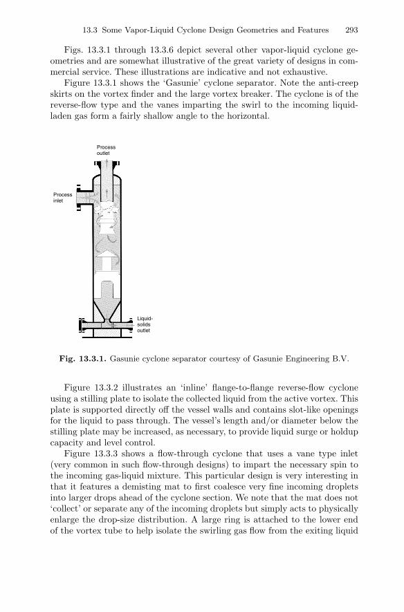
Figure 13.3.1 shows the ‘Gasunie’ cyclone separator. Note the anti-creepskirts on the vortex finder and the large vortex breaker. The cyclone is of thereverse-flow type and the vanes imparting the swirl to the incoming liquid-laden gas form a fairly shallow angle to the horizontal.
Process inlet
Liquid- solids outlet
Process outlet
Fig. 13.3.1. Gasunie cyclone separator courtesy of Gasunie Engineering B.V.
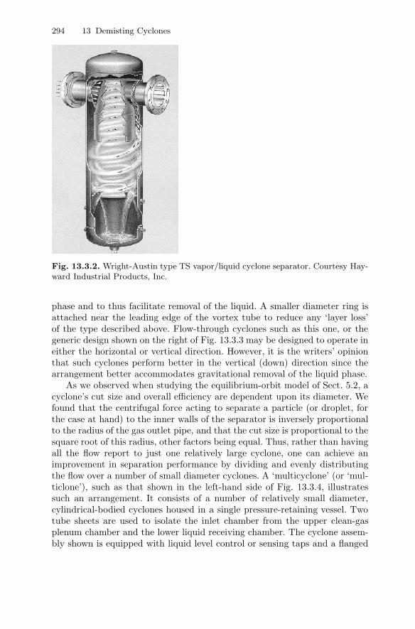
Figure 13.3.2 illustrates an ‘inline’ flange-to-flange reverse-flow cycloneusing a stilling plate to isolate the collected liquid from the active vortex. Thisplate is supported directly off the vessel walls and contains slot-like openingsfor the liquid to pass through. The vessel’s length and/or diameter below thestilling plate may be increased, as necessary, to provide liquid surge or holdupcapacity and level control.
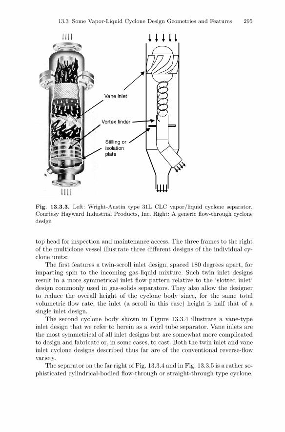
Figure 13.3.3 shows a flow-through cyclone that uses a vane type inlet(very common in such flow-through designs) to impart the necessary spin tothe incoming gas-liquid mixture. This particular design is very interesting inthat it features a demisting mat to first coalesce very fine incoming dropletsinto larger drops ahead of the cyclone section. We note that the mat does not‘collect’ or separate any of the incoming droplets but simply acts to physicallyenlarge the drop-size distribution. A large ring is attached to the lower endof the vortex tube to help isolate the swirling gas flow from the exiting liquid
294 13 Demisting Cyclones
Fig. 13.3.2. Wright-Austin type TS vapor/liquid cyclone separator. Courtesy Hay-ward Industrial Products, Inc.
phase and to thus facilitate removal of the liquid. A smaller diameter ring isattached near the leading edge of the vortex tube to reduce any ‘layer loss’of the type described above. Flow-through cyclones such as this one, or thegeneric design shown on the right of Fig. 13.3.3 may be designed to operate ineither the horizontal or vertical direction. However, it is the writers’ opinionthat such cyclones perform better in the vertical (down) direction since thearrangement better accommodates gravitational removal of the liquid phase.
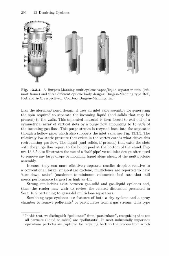
As we observed when studying the equilibrium-orbit model of Sect. 5.2, acyclone’s cut size and overall efficiency are dependent upon its diameter. Wefound that the centrifugal force acting to separate a particle (or droplet, forthe case at hand) to the inner walls of the separator is inversely proportionalto the radius of the gas outlet pipe, and that the cut size is proportional to thesquare root of this radius, other factors being equal. Thus, rather than havingall the flow report to just one relatively large cyclone, one can achieve animprovement in separation performance by dividing and evenly distributingthe flow over a number of small diameter cyclones. A ‘multicyclone’ (or ‘mul-ticlone’), such as that shown in the left-hand side of Fig. 13.3.4, illustratessuch an arrangement. It consists of a number of relatively small diameter,cylindrical-bodied cyclones housed in a single pressure-retaining vessel. Twotube sheets are used to isolate the inlet chamber from the upper clean-gasplenum chamber and the lower liquid receiving chamber. The cyclone assem-bly shown is equipped with liquid level control or sensing taps and a flanged
13.3 Some Vapor-Liquid Cyclone Design Geometries and Features 295
Vane inlet
Vortex finder
Stilling or isolation plate
Fig. 13.3.3. Left: Wright-Austin type 31L CLC vapor/liquid cyclone separator.Courtesy Hayward Industrial Products, Inc. Right: A generic flow-through cyclonedesign
top head for inspection and maintenance access. The three frames to the rightof the multiclone vessel illustrate three different designs of the individual cy-clone units:
The first features a twin-scroll inlet design, spaced 180 degrees apart, forimparting spin to the incoming gas-liquid mixture. Such twin inlet designsresult in a more symmetrical inlet flow pattern relative to the ‘slotted inlet’design commonly used in gas-solids separators. They also allow the designerto reduce the overall height of the cyclone body since, for the same totalvolumetric flow rate, the inlet (a scroll in this case) height is half that of asingle inlet design.
The second cyclone body shown in Figure 13.3.4 illustrate a vane-typeinlet design that we refer to herein as a swirl tube separator. Vane inlets arethe most symmetrical of all inlet designs but are somewhat more complicatedto design and fabricate or, in some cases, to cast. Both the twin inlet and vaneinlet cyclone designs described thus far are of the conventional reverse-flowvariety.
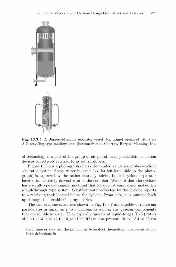
The separator on the far right of Fig. 13.3.4 and in Fig. 13.3.5 is a rather so-phisticated cylindrical-bodied flow-through or straight-through type cyclone.
296 13 Demisting Cyclones
Fig. 13.3.4. A Burgess-Manning multicyclone vapor/liquid separator unit (left-most frame) and three different cyclone body designs: Burgess-Manning type R-T,R-A and A-X, respectively. Courtesy Burgess-Manning, Inc.
Like the aforementioned design, it uses an inlet vane assembly for generatingthe spin required to separate the incoming liquid (and solids that may bepresent) to the walls. This separated material is then forced to exit out of asymmetrical array of vertical slots by a purge flow amounting to 15–20% ofthe incoming gas flow. This purge stream is recycled back into the separatorthough a hollow pipe, which also supports the inlet vane, see Fig. 13.3.5. Therelatively low static pressure that exists in the vortex core is what drives thisrecirculating gas flow. The liquid (and solids, if present) that exits the slotswith the purge flow report to the liquid pool at the bottom of the vessel. Fig-ure 13.3.5 also illustrates the use of a ‘half-pipe’ vessel inlet design often usedto remove any large drops or incoming liquid slugs ahead of the multicycloneassembly.
Because they can more effectively separate smaller droplets relative toa conventional, large, single-stage cyclone, multiclones are reported to have‘turn-down ratios’ (maximum-to-minimum volumetric feed rate that stillmeets performance targets) as high as 4:1.
Strong similarities exist between gas-solid and gas-liquid cyclones and,thus, the reader may wish to review the related discussion presented inSect. 16.2 pertaining to gas-solid multiclone separators.
Scrubbing type cyclones use features of both a dry cyclone and a spraychamber to remove pollutants1 or particulates from a gas stream. This type
1 In this text, we distinguish “pollutants” from “particulates”, recognizing that notall particles (liquid or solids) are “pollutants”. In most industrially importantoperations particles are captured for recycling back to the process from which
13.3 Some Vapor-Liquid Cyclone Design Geometries and Features 297
Fig. 13.3.5. A Burgess-Manning separator vessel (top frame) equipped with typeA-X recycling type multicyclones (bottom frame). Courtesy Burgess-Manning, Inc.
of technology is a part of the group of air pollution or particulate collectiondevices collectively referred to as wet scrubbers.
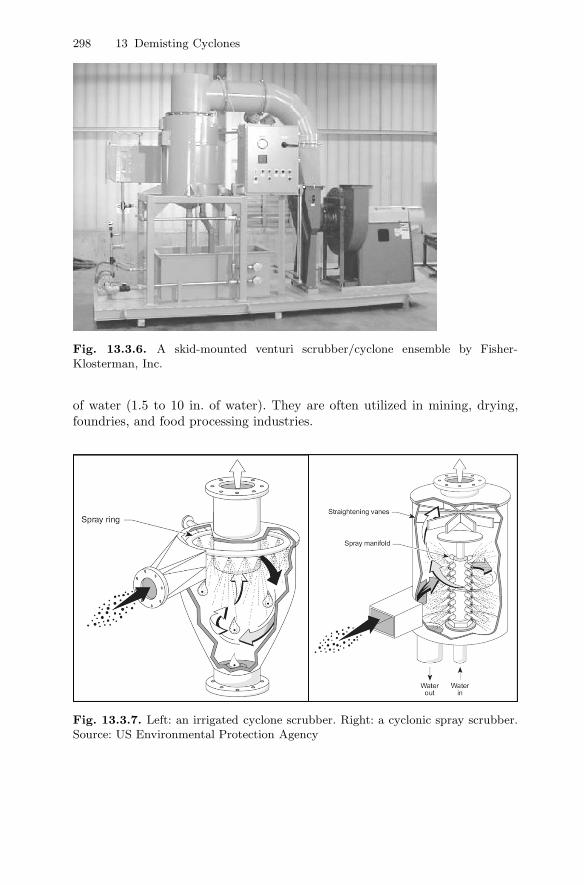
Figure 13.3.6 is a photograph of a skid-mounted venturi-scrubber/cycloneseparator system. Spray water injected (see far left-hand side in the photo-graph) is captured by the rather short cylindrical-bodied cyclone separatorlocated immediately downstream of the scrubber. We note that the cyclonehas a scroll-type rectangular inlet and that the downstream blower makes thisa pull-through type system. Scrubber water collected by the cyclone reportsto a receiving tank located below the cyclone. From here, it is pumped backup through the scrubber’s spray nozzles.
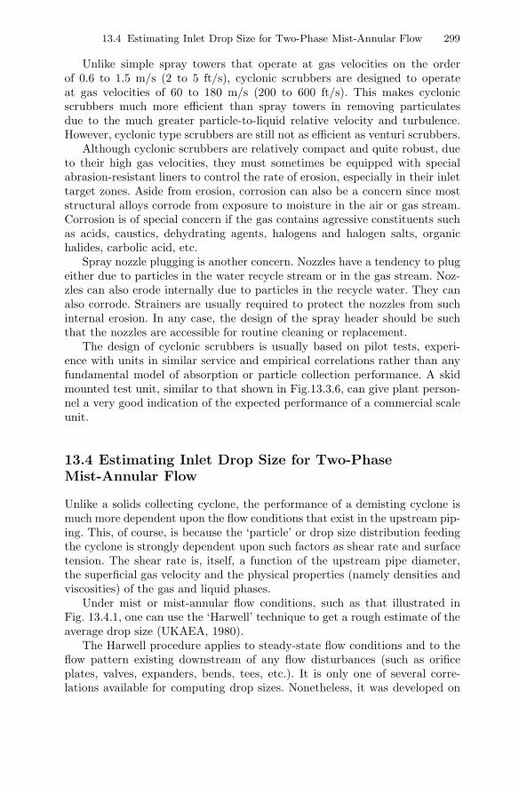
The two cyclonic scrubbers shown in Fig. 13.3.7 are capable of removingparticulates as small as 2 to 3 microns as well as any gaseous componentsthat are soluble in water. They typically operate at liquid-to-gas (L/G) ratiosof 0.3 to 1.3 l/m3 (2 to 10 gal/1000 ft3) and at pressure drops of 4 to 25 cm
they came or they are the product or byproduct themselves. In some situationsboth definitions fit.
298 13 Demisting Cyclones
Fig. 13.3.6. A skid-mounted venturi scrubber/cyclone ensemble by Fisher-Klosterman, Inc.
of water (1.5 to 10 in. of water). They are often utilized in mining, drying,foundries, and food processing industries.
Fig. 13.3.7. Left: an irrigated cyclone scrubber. Right: a cyclonic spray scrubber.Source: US Environmental Protection Agency
13.4 Estimating Inlet Drop Size for Two-Phase Mist-Annular Flow 299
Unlike simple spray towers that operate at gas velocities on the orderof 0.6 to 1.5 m/s (2 to 5 ft/s), cyclonic scrubbers are designed to operateat gas velocities of 60 to 180 m/s (200 to 600 ft/s). This makes cyclonicscrubbers much more efficient than spray towers in removing particulatesdue to the much greater particle-to-liquid relative velocity and turbulence.However, cyclonic type scrubbers are still not as efficient as venturi scrubbers.
Although cyclonic scrubbers are relatively compact and quite robust, dueto their high gas velocities, they must sometimes be equipped with specialabrasion-resistant liners to control the rate of erosion, especially in their inlettarget zones. Aside from erosion, corrosion can also be a concern since moststructural alloys corrode from exposure to moisture in the air or gas stream.Corrosion is of special concern if the gas contains agressive constituents suchas acids, caustics, dehydrating agents, halogens and halogen salts, organichalides, carbolic acid, etc.
Spray nozzle plugging is another concern. Nozzles have a tendency to plugeither due to particles in the water recycle stream or in the gas stream. Noz-zles can also erode internally due to particles in the recycle water. They canalso corrode. Strainers are usually required to protect the nozzles from suchinternal erosion. In any case, the design of the spray header should be suchthat the nozzles are accessible for routine cleaning or replacement.
The design of cyclonic scrubbers is usually based on pilot tests, experi-ence with units in similar service and empirical correlations rather than anyfundamental model of absorption or particle collection performance. A skidmounted test unit, similar to that shown in Fig.13.3.6, can give plant person-nel a very good indication of the expected performance of a commercial scaleunit.
13.4 Estimating Inlet Drop Size for Two-PhaseMist-Annular Flow
Unlike a solids collecting cyclone, the performance of a demisting cyclone ismuch more dependent upon the flow conditions that exist in the upstream pip-ing. This, of course, is because the ‘particle’ or drop size distribution feedingthe cyclone is strongly dependent upon such factors as shear rate and surfacetension. The shear rate is, itself, a function of the upstream pipe diameter,the superficial gas velocity and the physical properties (namely densities andviscosities) of the gas and liquid phases.
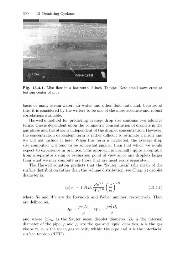
Under mist or mist-annular flow conditions, such as that illustrated inFig. 13.4.1, one can use the ‘Harwell’ technique to get a rough estimate of theaverage drop size (UKAEA, 1980).
The Harwell procedure applies to steady-state flow conditions and to theflow pattern existing downstream of any flow disturbances (such as orificeplates, valves, expanders, bends, tees, etc.). It is only one of several corre-lations available for computing drop sizes. Nonetheless, it was developed on
300 13 Demisting Cyclones
Fig. 13.4.1. Mist flow in a horizontal 2 inch ID pipe. Note small wave crest atbottom center of pipe
basis of many steam-water, air-water and other fluid data and, because ofthis, it is considered by the writers to be one of the more accurate and robustcorrelations available.
Harwell’s method for predicting average drop size contains two additiveterms. One is dependent upon the volumetric concentration of droplets in thegas phase and the other is independent of the droplet concentration. However,the concentration dependent term is rather difficult to estimate a priori andwe will not include it here. When this term is neglected, the average dropsize computed will tend to be somewhat smaller than that which we wouldexpect to experience in practice. This approach is normally quite acceptablefrom a separator sizing or evaluation point of view since any droplets largerthan what we may compute are those that are most easily separated.
The Harwell equation predicts that the ‘Sauter mean’ (the mean of thesurface distribution rather than the volume distribution, see Chap. 2) dropletdiameter is:
〈x〉Sa = 1.91DtRe0.1
We0.6
(ρ
ρl
)0.6
(13.4.1)
where Re and We are the Reynolds and Weber number, respectively. Theyare defined as,
Re =ρvtDt
µ, We =
ρv2tDt
σ
and where 〈x〉Sa is the Sauter mean droplet diameter. Dt is the internaldiameter of the pipe, ρ and ρl are the gas and liquid densities, µ is the gasviscosity, vt is the mean gas velocity within the pipe and σ is the interfacialsurface tension (‘IFT’)
13.4 Estimating Inlet Drop Size for Two-Phase Mist-Annular Flow 301
The Weber number can be understood as the ratio of inertial forces, whichtend to break a droplet apart, and surface tension forces, which tend to holdit together.
In certain mass-transfer operations, such as spray columns, the Sautermean diameter is a useful quantity to know. However, in studies of dropleterosion or droplet separation, the volume or mass median diameter is morephysically meaningful. This volume-average (median) drop diameter is relatedto the Sauter-mean diameter through the following approximation (AIChE,1978).
〈x〉med = 1.42xSa. (13.4.2)
An example calculation for estimating the Sauter mean droplet size inpipelines is included in Appendix 13.A.
13.4.1 Estimating Drop Size Distribution
The preceding section provides us with a technique for estimating the volume-averaged drop size of a collection of droplets flowing within a pipe undermist-annular flow conditions. And while this is often all that one may wish toknow about the droplet distribution, it is sometimes of interest to know, orat least estimate, the entire drop size distribution. Such would be the case ifone wished to perform a cyclone simulation study which required, as input,an estimate of the inlet drop size distribution which may exist within theupstream pipe feeding the cyclone.
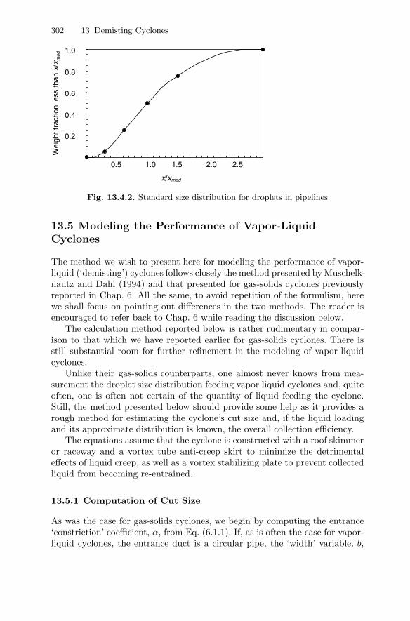
Fortunately, it turns out (AIChE, 1978) that the width of the drop sizedistribution is strongly dependent upon the volume or mass average dropletsize, xmed, as previously computed. Furthermore, if the drop size distribution[i.e., F (x)] is normalized by dividing each x by xmed, then, as a rough ap-proximation, all droplet distributions are identical and can be represented asshown in Table 13.4.1 and 13.4.2:
Table 13.4.1. Points on the standard size distribution for droplets
x/xmed 0 0.3 0.62 1 1.5 2.9F (x/xmed) 0 0.05 0.25 0.5 0.75 1.0
For this distribution the mean size 〈x〉 is almost equal to the median sizexmed.
We may note that:
• only about 5% of the droplets will be of size x/xmed = 0.30 or less• 100% will be less than x/xmed = 2.9
In Appendix 13.A, an example calculation showing how to use this stan-dard droplet distribution is given.
302 13 Demisting Cyclones
0.5 1.0 1.5 2.0 2.5
0.2
0.4
0.6
0.8
1.0 W
eigh
t fra
ctio
n le
ss th
an x
/xm
ed
x/xmed
Fig. 13.4.2. Standard size distribution for droplets in pipelines
13.5 Modeling the Performance of Vapor-LiquidCyclones
The method we wish to present here for modeling the performance of vapor-liquid (‘demisting’) cyclones follows closely the method presented by Muschelk-nautz and Dahl (1994) and that presented for gas-solids cyclones previouslyreported in Chap. 6. All the same, to avoid repetition of the formulism, herewe shall focus on pointing out differences in the two methods. The reader isencouraged to refer back to Chap. 6 while reading the discussion below.
The calculation method reported below is rather rudimentary in compar-ison to that which we have reported earlier for gas-solids cyclones. There isstill substantial room for further refinement in the modeling of vapor-liquidcyclones.
Unlike their gas-solids counterparts, one almost never knows from mea-surement the droplet size distribution feeding vapor liquid cyclones and, quiteoften, one is often not certain of the quantity of liquid feeding the cyclone.Still, the method presented below should provide some help as it provides arough method for estimating the cyclone’s cut size and, if the liquid loadingand its approximate distribution is known, the overall collection efficiency.
The equations assume that the cyclone is constructed with a roof skimmeror raceway and a vortex tube anti-creep skirt to minimize the detrimentaleffects of liquid creep, as well as a vortex stabilizing plate to prevent collectedliquid from becoming re-entrained.
13.5.1 Computation of Cut Size
As was the case for gas-solids cyclones, we begin by computing the entrance‘constriction’ coefficient, α, from Eq. (6.1.1). If, as is often the case for vapor-liquid cyclones, the entrance duct is a circular pipe, the ‘width’ variable, b,
13.6 Criteria for Determining if ‘Mass loading’ (‘Saltation’) Occurs 303
appearing in the formula ξ = b/(12D) = b/R, is to be interpreted as the
inside diameter of the cyclone’s inlet pipe, de. In addition, the inlet loadingvariable, co, is now defined as the ratio of the mass of incoming liquid to massof incoming gas in the feed stream.
We compute the tangential velocity of the gas at the ‘inner core’ radius,RCS , by following the calculation procedure leading up to Eq. (6.2.1) andby using the same equation reported therein for the frictional area term,AR.However, for the computation of the total friction factor, f , we do not useEq. (6.1.11) but the simpler, approximate expression geared to liquids:
f = fair
(1 + 0.4c0.1
o
)(13.5.1)
where, as before, fair is the gas-only friction factor computed from Fig. 6.1.3.The term in parenthesis above is a liquid-loading correction factor to the gas-only friction factor. It varies in magnitude from 1, at negligible loadings, to1.4 at a inlet loading of 1.0. Its dependency upon loading is very weak beyonda loading of about 0.1. That is, a thicker film of liquid on the wall does notoffer much more resistance to flow than a thinner film.
The all-important cut size or cut-point diameter of the inner vortex maynow be computed directly from Eq. (6.2.3) or, if necessary, Eq. (6.2.6) wherethe particle density, ρp, now refers to the density of the liquid phase.
13.5.2 Computation of Efficiency at Low Inlet Loadings
In this section we will compute the grade-efficiency curve and overall separa-tion efficiency at low inlet loadings (co < coL)—the classification-only case.
The grade-efficiency curve one uses to quantify separation efficiency as afunction of particle (drop) size should be based on experimental data or plantmeasurements taken on a cyclone of similar design and operation. However,lacking such information, we suggest, as before, using Eq. (6.3.2) with a ‘slope’,m, of about 3.
Overall collection efficiency is again computed from Eq. (6.3.3) by sum-ming up the efficiencies of the individual size fractions, weighted by their massfraction in the incoming feed.
13.6 Criteria for Determining if ‘Mass loading’(‘Saltation’) Occurs
In analogy to our gas-solids cyclones, the amount of liquid that the gas phasecan hold in turbulent suspension upon its entrance into a cyclone depends onthe mass average drop size of the feed, 〈x〉, the cut-point of the ‘inlet wallregion’, x50in, and, to a lesser extent, the inlet loading itself, co. For gas-liquid cyclones, Muschelknautz and Dahl (1994) report for the limit-loadingconcentration:
304 13 Demisting Cyclones
coL = 0.0078(x50in
〈x〉)
(10cok)k for 0.01 < cok > 0.5 (13.6.1)
wherek = 0.07 − 0.16 ln cok (13.6.2)
and where cok is the mass of liquid suspended in the incoming gas streamper unit mass of gas. However, introducing the quantity x50in complicatesthe analysis considerably. Furthermore, our calculations show that x50in istypically only about 25% greater than the cut size of the inner vortex, x50,calculated by Eq. (6.2.3). For these reasons, we will substitute x50for x50in
and rewrite Eq. (13.6.1) as,
coL = 0.0078(x50
〈x〉)
(10cok)k for 0.01 < cok > 0.5. (13.6.3)
As mentioned above, cok is the mass of liquid suspended in the incominggas stream per unit mass of gas. As such, it will always be less than the totalliquid loading since some portion of the incoming liquid will always enter thecyclone as ‘wall flow’. Yet, in most practical applications, we do not knowcok since it is difficult or impractical to either measure in an operating plantor to predict, in general, from fluid flow considerations. However, if we usethe total incoming liquid loading, co, in place of the suspension loading,cok,in Eq. (13.6.3), the result will be ‘conservative’ as far as overall separationefficiency is concerned. This is because the actual limit-loading will, in reality,be less than that computed using the total entrance liquid loading, co, andany liquid entering the cyclone in excess of coL will be captured immediatelyupon entrance. Thus, we shall use the total liquid loading, co, in Eq. (13.6.3)knowing that our estimate of the amount of liquid that may be capturedbecause it exceeds the limit-loading will be a conservative one. In the eventthat the incoming liquid loading exceeds 0.5, we recommend using 0.5 for cok
in Eq. (13.6.3).If co < coL, then there is no ‘mass loading’ effect and the comparatively
simple method for computing the cyclone’s separation performance, as de-scribed in Sects. 13.5.1 and 13.5.2, applies. Conditions that may lead to thisscenario include a low liquid loading, co, a very fine feed drop size distribution,and a large inner vortex cut-point diameter, x50.
If co > coL, then ‘mass loading’ will occur and the cyclone will, in effect,become a two-stage separator: separating a portion of the incoming liquidimmediately upon its entrance into the cyclone and a portion of the remainingliquid via classification in the spinning inner core.
13.6.1 Overall Separation Efficiency when co > coL
As we reported for gas-solids cyclones, the overall or total efficiency for gas-liquid cyclones under mass loading or saltation conditions also includes a
13.7 Re-entrainment From Demisting Cyclones 305
‘saltation’ and a ‘classification’ contribution. A portion of the incoming liquidthat is not collected by the former is collected by the latter, so that the totalefficiency becomes:
η =(
1 − coL
co
)+(coL
co
) N∑i=1
ηi ×∆MFi (13.6.4)
where, again, ∆MF i is the ith mass fraction and ηi is the capture efficiencyfor the ith size fraction computed via Eq. (6.3.2) with x50 obtained fromEq. (6.2.3).
13.7 Re-entrainment From Demisting Cyclones
Although re-entrainment, as mentioned in the beginning of this chapter, ismuch less of a problem in demisting than in dedusting cyclones, demistingcyclones are in some practical applications operated at such severe conditionsthat re-entrainment does, nevertheless, become the limiting factor for separa-tion. For example, with the push to process natural gas under high gas andliquid loads and at high pressure, the physical properties of the gas and liq-uid are becoming more challenging in terms of separation efficiency. Also forgas processing off-shore and sub-sea the accuracy and robustness of modelspredicting the separation efficiency is more crucial, since the consequences ofequipment failure are more severe in such applications.
13.7.1 Re-entrainment Mechanisms and Governing Parameters
Only little work focusing on high liquid loading in, and re-entrainment from,demisting cyclones has been published, although some is beginning to emergein the research literature. Ng et al. (2006) studied flooding phenomena in,and entrainment from, once-through swirl tubes with upflow. They installedand tested radical design improvements to the swirl vanes, using vanes withperipheral rather than axial inflow, to significantly delay the onset of floodingand entrainment.
Below we give a short account of some work that has been done in one ofthe author’s (Hoffmann) own research group (Austrheim, 2005) in the frame-work of the HiPGaS (High Pressure Gas Separation) project, which shedssome light on the nature of the phenomenon of re-entrainment, and pointsthe way to the formulation of predictive models.
Re-entrainment from cyclones may take place due to droplet entrainmentfrom the film of separated liquid on the cyclone wall close to the exit fromthe cyclone, or from some edge at the outlet. We focus on the former, andassume that if re-entrainment takes place from an edge rather than a wall,the parameters governing the process will be the same or similar.
306 13 Demisting Cyclones
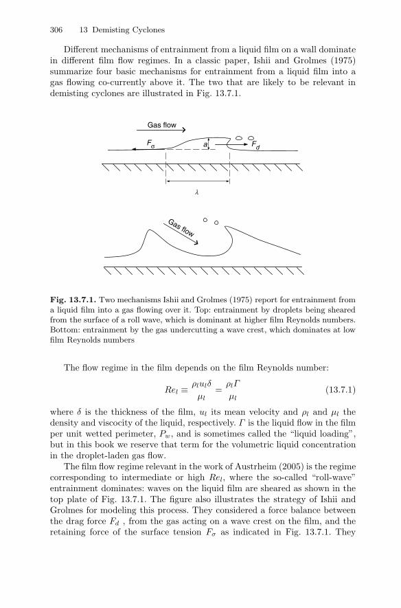
Different mechanisms of entrainment from a liquid film on a wall dominatein different film flow regimes. In a classic paper, Ishii and Grolmes (1975)summarize four basic mechanisms for entrainment from a liquid film into agas flowing co-currently above it. The two that are likely to be relevant indemisting cyclones are illustrated in Fig. 13.7.1.
Gas flow
Gas flow
a FdFσ
λ
Fig. 13.7.1. Two mechanisms Ishii and Grolmes (1975) report for entrainment froma liquid film into a gas flowing over it. Top: entrainment by droplets being shearedfrom the surface of a roll wave, which is dominant at higher film Reynolds numbers.Bottom: entrainment by the gas undercutting a wave crest, which dominates at lowfilm Reynolds numbers
The flow regime in the film depends on the film Reynolds number:
Rel ≡ ρlulδ
µl=ρlΓ
µl(13.7.1)
where δ is the thickness of the film, ul its mean velocity and ρl and µl thedensity and viscocity of the liquid, respectively. Γ is the liquid flow in the filmper unit wetted perimeter, Pw, and is sometimes called the “liquid loading”,but in this book we reserve that term for the volumetric liquid concentrationin the droplet-laden gas flow.
The film flow regime relevant in the work of Austrheim (2005) is the regimecorresponding to intermediate or high Rel, where the so-called “roll-wave”entrainment dominates: waves on the liquid film are sheared as shown in thetop plate of Fig. 13.7.1. The figure also illustrates the strategy of Ishii andGrolmes for modeling this process. They considered a force balance betweenthe drag force Fd , from the gas acting on a wave crest on the film, and theretaining force of the surface tension Fσ as indicated in Fig. 13.7.1. They
13.7 Re-entrainment From Demisting Cyclones 307
considered that roll wave entrainment would take place when the drag forceexceeds the retaining force:
Fd ≥ Fσ. (13.7.2)
We have to refer to their paper for the details of the derivation, but theircriterion for the onset of entrainment is:
µlug
σ
√ρg
ρl≥ 11.78N0.8
µ Re−1/3l for Nµ ≤ 1
15µlug
σ
√ρg
ρl≥ 1.35Re−1/3
l for Nµ ≥ 115
. (13.7.3)
We mention that at high values of Rel, the criterion becomes independent ofRel, and therefore simpler. In Eq. (13.7.3), Nµ is a “viscosity number”, whichmeasures the ratio of the viscous force due to the internal flow in the wave tothe force due to surface tension:
Nµ ≡ µl√ρlσ√
σg∆ρ
, (13.7.4)
where ∆ρ is the difference between the liquid and gas densities.In applying this to cyclone demisters, Austrheim (2005) assumed that the
cyclone efficiency, when limited by re-entrainment, is a function of the ratio ofFd and Fσ, such that the efficiency can be written:
ηentr(a) = f
⎛⎝
µlug
σ
√ρg
ρl
NaµRe
−1/3l
⎞⎠ , (13.7.5)
calling the group on the right-hand-side the re-entrainment number . Ishii andGrolmes (1975) and Austrheim (2005) adjusted the value of the exponent ato optimize the performance of their models, Austrheim finding the optimalvalue to be 0.4.
The Reynolds number of the film, which is swirling around the wall of acyclone, was calculated as:
Rel =ρlulδ
µl=Qηρl
Pwµl(13.7.6)
where Pw is taken as πD/ cosα. Q is the total liquid flow to the cyclone, ηis the fraction separated to the wall and α is the angle to the horizontal ofthe liquid flow. The latter is taken as equal to the angle to the horizontal atwhich the gas flows, which again, in the vaned swirl tube used by Austrheim,is taken as equal to the exit angle, β, of the vanes.
Since the liquid film in cyclones is swirling around the wall rather thanrunning along the wall in a gravity field, g in Eq. (13.7.4) needs to be replaced
308 13 Demisting Cyclones
by the centripetal acceleration of the film, which is the square of the tangentialfilm velocity divided by the radius of the cyclone wall, u2
θ,l/R.This makes it necessary to determine uθ,l = ul cosα, where ul is the ab-
solute velocity in the liquid film. By a procedure similar to that used by Ishiiand Grolmes (1975), Austrheim (2005) derives the following expression forul,θ:
ul,θ =
√fg,iρgug,θ
fl,wρl, (13.7.7)
where fg,i and fl,w are the friction factors between the gas and the liquid filmsurface and the liquid film and the wall, respectively, found from:
fg,i = 0.005(
1 + 300δ
R
)
√fl,w = K · Rem
l where:{K = 3.73;m = −0.47 for 2 < Rel < 100K = 1.96;m = −1/3 for 100 < Rel < 1000
(13.7.8)
Finally, to calculate fg,i, we need δ, the thickness of the liquid film, whichis calculated as:
δ =Q
Pwul=Q cosαPwul,θ
=Q cos2 απDul,θ
(13.7.9)
u2θ,l/R should thus replace g in Eq. (13.7.4) when calculating Nµ for use
in Eq. (13.7.5).As an aside, we can mention at this point that, as an alternative to the
dimensionless parameters of Ishii and Grolmes (1975), van Rossum (1959)used the Weber number for the liquid film, with the film thickness as lengthscale, and a “correlation parameter”, S:
We ≡ ρgv2gδ
σS ≡ ugµl
σ(13.7.10)
to correlate data for the inception of entrainment from a liquid film. Forvelocities higher than 25 m/s he found that the critical Weber number forinception of entrainment was practically independent of S for S > 5, while itbecame dependent on S for lower S-values.
13.7.2 Data for Re-entrainment
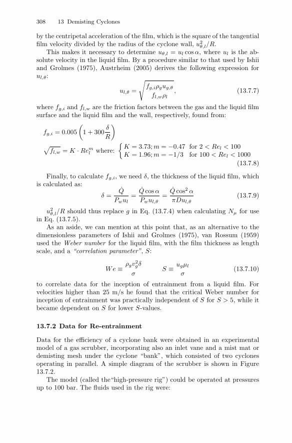
Data for the efficiency of a cyclone bank were obtained in an experimentalmodel of a gas scrubber, incorporating also an inlet vane and a mist mat ordemisting mesh under the cyclone “bank”, which consisted of two cyclonesoperating in parallel. A simple diagram of the scrubber is shown in Figure13.7.2.
The model (called the“high-pressure rig”) could be operated at pressuresup to 100 bar. The fluids used in the rig were:
13.7 Re-entrainment From Demisting Cyclones 309
Inlet vane
Cyclone bank
Mist mat
Outflow
Inflow
Fig. 13.7.2. Diagram of the scrubber tested by Austrheim (2005)
• air/Exxsol D60, Exxsol D60 is a commercial hydrocarbon liquid• a synthetic “live” natural gas system, the gas being synthesized from
methane, ethane and N-pentane.
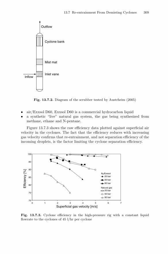
Figure 13.7.3 shows the raw efficiency data plotted against superficial airvelocity in the cyclones. The fact that the efficiency reduces with increasinggas velocity confirms that re-entrainment, and not separation efficiency of theincoming droplets, is the factor limiting the cyclone separation efficiency.
70
75
80
85
90
95
100
0 1 2 3 4 5 6 7
Superficial gas velocity [m/s]
Effi
cien
cy [%
]
20 bar
50 bar
92 bar
20 bar
50 bar
92 bar
N2/Exxsol
Natural gas
Fig. 13.7.3. Cyclone efficiency in the high-pressure rig with a constant liquidflowrate to the cyclones of 45 l/hr per cyclone
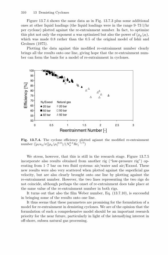
310 13 Demisting Cyclones
Figure 13.7.4 shows the same data as in Fig. 13.7.3 plus some additionalones at other liquid loadings (the liquid loadings were in the range 9–73 l/hrper cyclone) plotted against the re-entrainment number. In fact, to optimizethis plot not only the exponent a was optimized but also the power of (ρg/ρl),which was made 0.8 rather than the 0.5 of the original model of Ishii andGrolmes (1975).
Plotting the data against this modified re-entrainment number clearlybrings all the results onto one line, giving hope that the re-entrainment num-ber can form the basis for a model of re-entrainment in cyclones.
50
55
60
65
70
75
80
85
90
95
100
0 0.5 1 1.5 2 2.5 3
Reentrainment Number [-]
Eff
icie
ncy
[%
]
20 bar
50 bar
92 bar
20 bar
50 bar
92 bar
N2/Exxsol Natural gas
Fig. 13.7.4. The cyclone efficiency plotted agianst the modified re-entrainmentnumber ([µlug/σ][ρg/ρl]
0.8)/(N0.4µ Re
−1/3l )
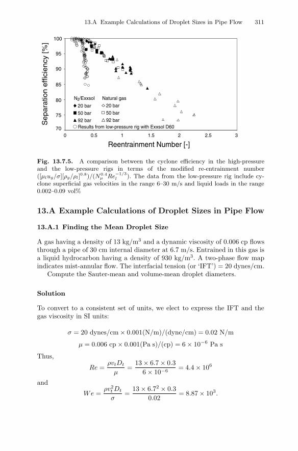
We stress, however, that this is still in the research stage. Figure 13.7.5incorporate also results obtained from another rig (“low-pressure rig”) op-erating from 1–7 bar on two fluid systems: air/water and air/Exxsol. Thesenew results were also very scattered when plotted against the superficial gasvelocity, but are also clearly brought onto one line by plotting against there-entrainment number. However, the two lines representing the two rigs donot coincide, although perhaps the onset of re-entrainment does take place atthe same value of the re-entrainment number in both rigs.
It turns out that also the film Weber number, Eq. (13.7.10), is successfulin bringing some of the results onto one line.
It thus seems that these parameters are promising for the formulation of amodel for re-entrainment in demisting cyclones. We are of the opinion that theformulation of such a comprehensive model should be an important researchpriority for the near future, particularly in light of the intensifying interest inoff-shore, subsea natural gas processing.
13.A Example Calculations of Droplet Sizes in Pipe Flow 311
0 0.5 1 1.5 2 2.5 3
Reentrainment Number [-]
Se
pa
ratio
n e
ffic
ien
cy [
%]
20 bar
50 bar
92 bar
20 bar
50 bar
92 bar
N2/Exxsol Natural gas
70
75
80
85
90
95
100
Results from low-pressure rig with Exxsol D60
Fig. 13.7.5. A comparison between the cyclone efficiency in the high-pressureand the low-pressure rigs in terms of the modified re-entrainment number([µlug/σ][ρg/ρl]
0.8)/(N0.4µ Re
−1/3l ). The data from the low-pressure rig include cy-
clone superficial gas velocities in the range 6–30 m/s and liquid loads in the range0.002–0.09 vol%
13.A Example Calculations of Droplet Sizes in Pipe Flow
13.A.1 Finding the Mean Droplet Size
A gas having a density of 13 kg/m3 and a dynamic viscosity of 0.006 cp flowsthrough a pipe of 30 cm internal diameter at 6.7 m/s. Entrained in this gas isa liquid hydrocarbon having a density of 930 kg/m3. A two-phase flow mapindicates mist-annular flow. The interfacial tension (or ‘IFT’) = 20 dynes/cm.
Compute the Sauter-mean and volume-mean droplet diameters.
Solution
To convert to a consistent set of units, we elect to express the IFT and thegas viscosity in SI units:
σ = 20 dynes/cm × 0.001(N/m)/(dyne/cm) = 0.02 N/m
µ = 0.006 cp × 0.001(Pa s)/(cp) = 6 × 10⁻⁶ Pa s
Thus,
Re =ρvtDt
µ=
13 × 6.7 × 0.36 × 10−6
= 4.4 × 10⁶
and
We =ρv2
tDt
σ=
13 × 6.72 × 0.30.02
= 8.87 × 10³.
312 13 Demisting Cyclones
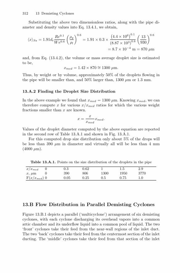
Substituting the above two dimensionless ratios, along with the pipe di-ameter and density values into Eq. 13.4.1, we obtain,
〈x〉Sa = 1.91dtRe0.1
We0.6
(ρg
ρl
)0.6
= 1.91 × 0.3 ×(4.4 × 106
)0.1
(8.87 × 10³)0.6
(13930
)0.6
= 8.7 × 10⁻⁴ m = 870 µm
and, from Eq. (13.4.2), the volume or mass average droplet size is estimatedto be,
xmed = 1.42 × 870 ∼= 1300 µm.
Thus, by weight or by volume, approximately 50% of the droplets flowing inthe pipe will be smaller than, and 50% larger than, 1300 µm or 1.3 mm.
13.A.2 Finding the Droplet Size Distribution
In the above example we found that xmed = 1300 µm. Knowing xmed, we cantherefore compute x for various x/xmed ratios for which the various weightfractions smaller than x are known.
x =x
xmedxmed.
Values of the droplet diameter computed by the above equation are reportedin the second row of Table 13.A.1 and shown in Fig. 13.A.1.
For this computed drop size distribution only about 5% of the drops willbe less than 390 µm in diameter and virtually all will be less than 4 mm(4000 µm).
Table 13.A.1. Points on the size distribution of the droplets in the pipe
x/xmed 0 0.3 0.62 1 1.5 2.9x, µm 0 390 806 1300 1950 3770F(x/xmed) 0 0.05 0.25 0.5 0.75 1.0
13.B Flow Distribution in Parallel Demisting Cyclones
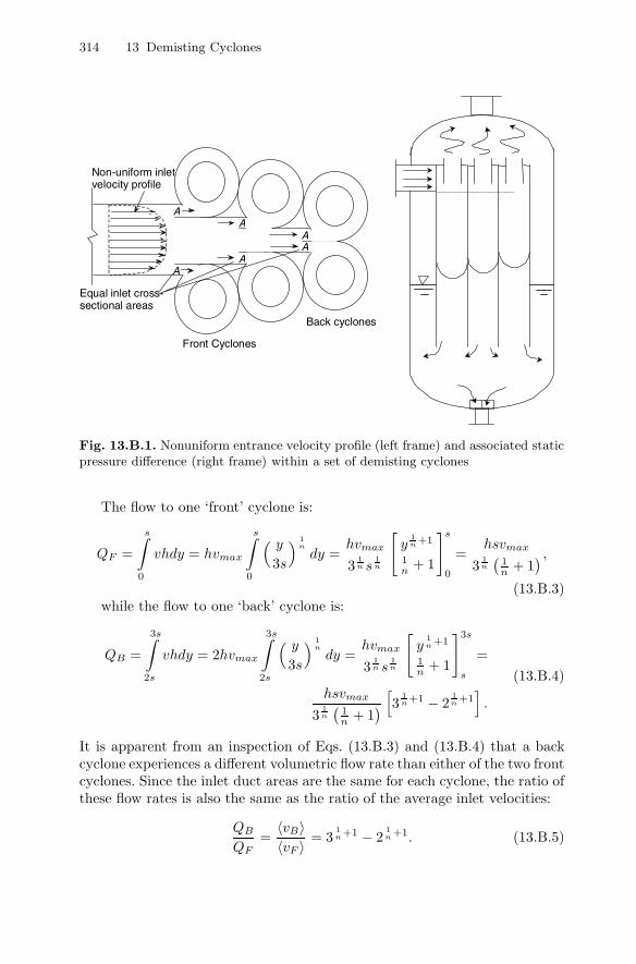
Figure 13.B.1 depicts a parallel (‘multicyclone’) arrangement of six demistingcyclones, with each cyclone discharging its overhead vapors into a commonattic chamber and its underflow liquid into a common pool of liquid. The two‘front’ cyclones take their feed from the near-wall regions of the inlet duct.The two ‘back’ cyclones take their feed from the centermost section of the inletducting. The ‘middle’ cyclones take their feed from that section of the inlet
13.B Flow Distribution in Parallel Demisting Cyclones 313
0.2
0.4
0.6
0.8
1.0 W
eigh
t fra
ctio
n le
ss th
an x
x (µm)
4000 3000 2000 1000 0
Fig. 13.A.1. Estimated drop size distribution for the example problem on basis ofthe AIChE design technique
ducting that lies between the wall and the middle of the entrance duct. Sincewall friction retards the flow near the two sidewalls of the inlet ducting, thetwo front cyclones experience a slightly lower impact pressure than either themiddle or back cyclones. This forces more vapor to flow into the back cyclonesthan to the two front cyclones. (Note, in this analysis, and for simplicity sake,we will focus attention on the two ‘front’ and ‘back’ cyclones.) This somewhatgreater vapor flow to the two back cyclones produces, in turn, a greater vortexspin and an attendant reduction in static pressure in the back cyclones relativeto the two front cyclones. This will manifest itself as a difference in liquidlevel within the bottoms of the cyclones. We can perform some basic fluidflow analysis on the configuration shown in Fig. 13.B.1 and thereby gain someinsight into the flow behavior therein.
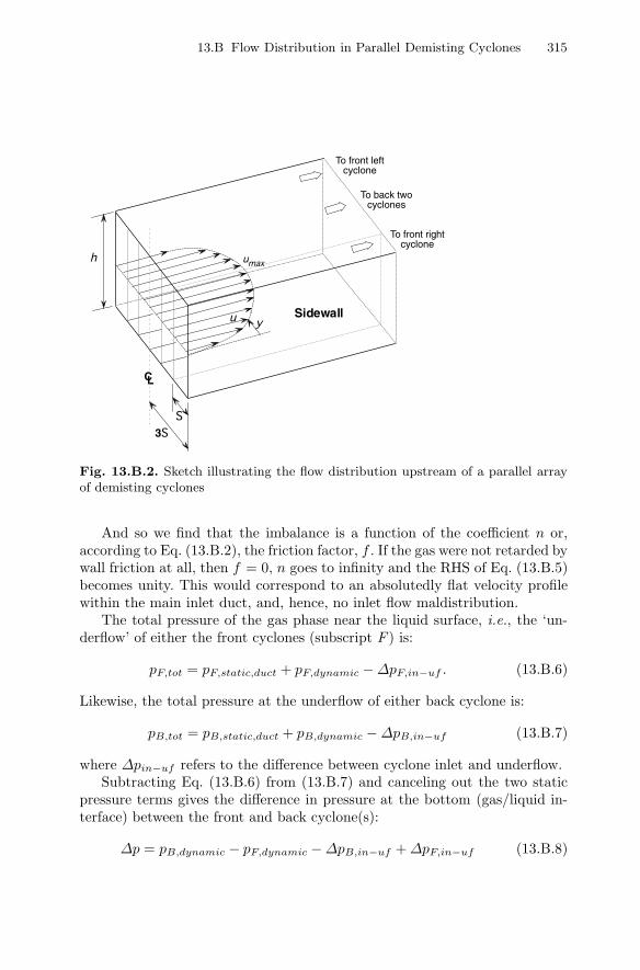
We begin by regarding the inlet ducting feeding the six cyclones as beingdivided into six equal-area rectangular openings each of height h and width s,as shown in Fig. 13.B.2 below. For estimation purposes, we will use an equationdescribing the velocity profile in a circular duct to describe the lateral velocityprofile in the rectangular ducting feeding the cyclones. Thus, the velocity vat a distance y from a sidewall is (Hinze, 1975).
v
vmax=( y
3s
) 1n
(13.B.1)
where v is the axial velocity a distance y from the side wall, vmax is themaximal axial velocity (at the entrance duct centerline), s is the width ofeach of the six entrance ducts, and
n =1√f
(13.B.2)
where f is the Moody friction factor for the inlet duct.
314 13 Demisting Cyclones
Front Cyclones
A A
A
Back cyclones
AA
A
Non-uniform inlet velocity profile
Equal inlet cross-sectional areas
Fig. 13.B.1. Nonuniform entrance velocity profile (left frame) and associated staticpressure difference (right frame) within a set of demisting cyclones
The flow to one ‘front’ cyclone is:
QF =
s∫
0
vhdy = hvmax
s∫
0
( y3s
) 1n
dy =hvmax
31n s
1n
[y
1n +1
1n + 1
]s
0
=hsvmax
31n
(1n + 1
) ,
(13.B.3)while the flow to one ‘back’ cyclone is:
QB =
3s∫
2s
vhdy = 2hvmax
3s∫
2s
( y3s
) 1n
dy =hvmax
31n s
1n
[y
1n +1
1n + 1
]3s
s
=
hsvmax
31n
(1n + 1
)[3
1n +1 − 2
1n +1].
(13.B.4)
It is apparent from an inspection of Eqs. (13.B.3) and (13.B.4) that a backcyclone experiences a different volumetric flow rate than either of the two frontcyclones. Since the inlet duct areas are the same for each cyclone, the ratio ofthese flow rates is also the same as the ratio of the average inlet velocities:
QB
QF=
〈vB〉〈vF 〉 = 3
1n +1 − 2
1n +1. (13.B.5)
13.B Flow Distribution in Parallel Demisting Cyclones 315
h
3S
C L
u y Sidewall
To front leftcyclone
To front rightcyclone
To back twocyclones
umax
S
Fig. 13.B.2. Sketch illustrating the flow distribution upstream of a parallel arrayof demisting cyclones
And so we find that the imbalance is a function of the coefficient n or,according to Eq. (13.B.2), the friction factor, f . If the gas were not retarded bywall friction at all, then f = 0, n goes to infinity and the RHS of Eq. (13.B.5)becomes unity. This would correspond to an absolutedly flat velocity profilewithin the main inlet duct, and, hence, no inlet flow maldistribution.
The total pressure of the gas phase near the liquid surface, i.e., the ‘un-derflow’ of either the front cyclones (subscript F ) is:
pF,tot = pF,static,duct + pF,dynamic −∆pF,in−uf . (13.B.6)
Likewise, the total pressure at the underflow of either back cyclone is:
pB,tot = pB,static,duct + pB,dynamic −∆pB,in−uf (13.B.7)
where ∆pin−uf refers to the difference between cyclone inlet and underflow.Subtracting Eq. (13.B.6) from (13.B.7) and canceling out the two static
pressure terms gives the difference in pressure at the bottom (gas/liquid in-terface) between the front and back cyclone(s):
∆p = pB,dynamic − pF,dynamic −∆pB,in−uf +∆pF,in−uf (13.B.8)
316 13 Demisting Cyclones
or,
∆p =12ρ〈vB〉2 − 1
2ρ〈vF 〉2 − 1
2ρKin−uf 〈vB〉2 +
12ρKin−uf 〈vF 〉2
(13.B.9)
with Kin−uf = inlet-to-underflow pressure loss coefficient. This coefficientmust be computed from either a cyclone model or calculated on basis of mea-surements on an operating unit or on a laboratory model of the operatingunit. The computation of Kin−uf requires one to measure or compute theinlet-to-underflow pressure difference, along with the gas density and averagevelocity in the upstream duct feeding one of the cyclones. Like the Euler num-ber, it is a constant and has the same value for each of the cyclones, assumedherein to be physically identical in their construction.
Equation (13.B.9) can be simplified to give:
∆p =12ρ (1 +Kin−uf )
(〈vF 〉2 − 〈vB〉2) . (13.B.10)
Equation 13.B.10 will give a positive number if the pressure at the bot-tom of the back cyclone(s) is greater than that at the bottom of the frontcyclone(s), and vice versa. The equation shows clearly that the difference inpressure between the bottoms of the front and back cyclones is dependentupon the difference in the square of the average velocity reporting to thesecyclones. The two average inlet duct velocities in Eq. 13.B.10 are obtained bydividing the inlet volumetric flow rates from Eqs. (13.B.3) and (13.B.4) bythe cross-sectional area of their inlet ducts, A. Doing so and substituting theresults into Eq. 13.B.10 we obtain, after simplification:
∆p =ρ ( 1 +Kin−uf )
2
[(3
1n +1 − 2
1n +1)− 1]2 [ vmax
31n
(1n + 1
)]2. (13.B.11)
As before, the pressure difference shown here vanishes if there is no frictionsuch that n→ ∞.
Obviously, the same sort of analysis and observations apply to any numberof cyclone pairs whose underflows discharge into a common liquid seal pool.One just needs to work through the detailed computations on a case-by-casebasis along the lines presented above.
In addition to vapor maldistribution, liquid maldistribution in the inletpiping will also give rise to a pressure imbalance within the bodies of front andback cyclones. This occurs because of the reduction in spin in the cyclone(s)that receive the greatest share of the liquid. This may not be a concern atthe low liquid loadings typically associated with demisting type cyclones. Atheavier loadings, however, one may need to modify the inlet piping to minimizeliquid segregation ahead of the individual cyclones.
A worked example for estimation of the static pressure difference betweendemisting cyclones arising from inlet maldistribution is presented next.
13.B Flow Distribution in Parallel Demisting Cyclones 317
13.B.1 Calculation of Flow Distribution
Given: An industrial demisting cyclone system consists of three pairs of iden-tical cyclones which share a common hopper, as shown in Fig. 13.B.1. It isestimated that the wall friction factor in the ducting leading up to the cycloneis 0.019 or about 30% greater than that for gas-only.
Compute: The flow imbalance ratio according to Eq. (13.B.5).
Solution
Substituting our Moody friction factor into Eq. (13.B.2), we find that n =7.5. This leads to the flow ratio: QB/QF = 〈vB〉/〈vF 〉 = 1.28. Thus, dueto the nonuniform velocity gradient in the inlet ducting, the back cycloneswill experience about 30% more vapor flow than the two front cyclones. It isinteresting to note that the computed value of the coefficient n, 7.5, is not toodifferent from the ‘Law of the Wall’ coefficient of 7 often used to describe thevelocity profile in fully developed turbulent flow within pipes.
13.B.2 Calculation of the Liquid Level Difference between theFront and Back Cyclones
Data for the cyclone system shown in Figs. 13.B.1 and 13.B.2 is as follows:
ρ = 11.9 kg/m3
Kin−uf = 2.6 (based on a cyclone simulation study)f = 0.018 (i.e., ∼=1.3 times fair)n = 7.5vmax = 〈v〉/0.80 = 18.2/0.80 = 22.8 m/s (approximately)
Substituting these values into Eq. 13.B.11, we obtain a pressure differencebetween the back and front cyclones of about -0.224 kPa (about -23 mm or -1inch of water column). Since this pressure differential (back - front) is negative,the liquid level in the two back cyclones will be 23 mm of water column higherthan that for the two front cyclones. The level in the two middle cyclones canbe expected to lie between that of the front and back cyclones.
Despite the rather large flow imbalance we found leading up to the entranceof the cyclones, this did not result in a significant difference in ‘bottom’ pres-sure among the cyclone pairs. However, as Eq. 13.B.11 shows, an increase inthe gas density (as in high pressure separators) and/or the flow rate throughthe main inlet duct would increase the pressure and elevation differences re-ported above. Furthermore, if the liquid phase reporting to the bottom ofthe cyclones were to be a low-density foam or froth, the difference in theirelevations would increase inversely with the decrease in the ‘liquid’s’ effec-tive density. If this foam column grew too high, it would become entrainedoverhead by the vortex and exit with the exiting gas phase.
318 13 Demisting Cyclones
Before closing this discussion we wish to call attention to the fact that theliquid seal at the bottom of each cyclone causes their performance to be ratherunaffected by flow imbalances of the type we just observed. This would notbe the case had the cyclone underflows not been isolated from one another.In this case, any pressure imbalance that would exist between the cycloneunderflows will cause gas to flow down some of the underflow openings andup other underflow openings. This, in turn can lead to a serious degradationof separation performance and is the reason why most multiclone systems donot perform as well as one of its individual cyclones tested in isolation.
When faced with a cyclone performance problem it is almost always ad-visable to focus attention on the underflow configuration. The majority ofperformance problems are due, for one reason or the other, to the inability ofparticulates to properly discharge out the underflow openings.
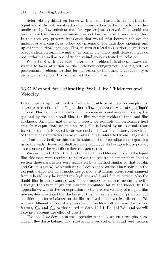
13.C Method for Estimating Wall Film Thickness andVelocity
In some special applications it is of value to be able to estimate certain physicalcharacteristics of the film of liquid that is flowing down the walls of a gas/liquidcyclone. This includes the fraction of the cross-sectional area occupied by thegas and by the liquid wall film, the film velocity, residence time, and filmthickness. Such information is of interest, for example, in performing heattransfer computations wherein the wall film is heated by an external steamjacket, or the film is cooled by an external chilled water enclosure. Knowledgeof the film characteristics is also of value if one is interested in ensuring that asufficient film velocity or thickness is maintained to keep solids from depositingupon the walls. Herein, we shall present a technique that is intended to providean estimate of the wall film’s flow characteristics.
We saw in Sect. 13.7.1 that the tangential liquid film velocity and the liquidfilm thickness were required to calculate the reentrainment number. In thatsection these parameters were estimated by a method similar to that of Ishiiand Grolmes (1975) by considering a force balance on the film resolved in thetangential direction. That model was geared to situations where reentrainmentfrom a liquid may be important: high gas and liquid film velocities. Also theliquid film in that example was being transported upward against gravity,although the effect of gravity was not accounted for in the model. In thisappendix we will derive an expression for the vertical velocity of a liquid filmmoving downward and the thickness of this film using a similar principle, butconsidering a force balance on the film resolved in the vertical direction. Wewill use different empirical expressions for the film-wall and gas-film frictionfactors, fl,w and fg,i to those used in Sect. 13.7.1, Eq. (13.7.8), and we willtake into account the effect of gravity.
The model we develop in this appendix is thus based on a two-phase, co-current flow force balance that relates the cross-sectional liquid void fraction
13.C Method for Estimating Wall Film Thickness and Velocity 319
(and, hence, the gas fraction) to the gas and liquid mass flow rates, physi-cal properties, cyclone diameter, wall and interfacial friction factors, and theacceleration of gravity. We assume that all of the liquid entering the cycloneis spun to the walls immediately upon entry and flows down as a uniformlythick film2, see Fig. 13.C.1.
Fig. 13.C.1. Simplified view of cyclone with liquid film of thickness t along wallwith gas comprising the core flow. Left image: cyclone overview. Right image: detailof a vertical segment of the cyclone
In most gas-liquid cyclone installations, the majority of all incoming liquidis deposited upon the walls immediately upon entry into the cyclone as a resultof the “mass loading” effect alone. This is due to the relatively large size ofthe incoming liquid drops and also to the “mass loading effect” discussed inSect. 13.6 above.
In this model, the primary purpose of the centrifugal force field generatedby the rotational motion imparted to the incoming feed stream is to conveyand keep the liquid on the walls of the cyclone. Herein we shall assume thatthe gas and liquid phases spiral down the walls of the cyclone in a helical2 A uniformly thick wall film is an idealized condition that is difficult to achieve in
practice. A vane-type inlet with multiple openings (distribution points) generallyprovides a much more uniform distribution of the liquid than that of a slot orpipe type inlet.
320 13 Demisting Cyclones
fashion at a common, constant angle relative to the horizontal. We may viewthe flow as that over a flat plate created by unfolding the cylindrical wallsof the cyclone. In this case, the gas and liquid flow paths are simply straightlines making a constant angle to the horizontal.
The force balance model equation that we shall derive below must besolved in an iterative manner for the vapor void fraction. Knowing this voidfraction and the cyclone diameter, the wall film thickness can be computed. Itis then possible to compute the average gas and wall film velocity, as well asthe “slip velocity”, the ratio of the average gas velocity to the average liquidfilm velocity.
13.C.1 Two-Phase, Co-current, Annular Force Balance, Resolvedin the Axial Direction
We begin by performing a force balance in the axial z direction over a crosssection of the cyclone of height dz. See Fig. 13.C.1. We shall assume that, forall practical purposes, all of the liquid is spiraling down the inner walls of thecyclone as a wall film with the gas phase comprising the core flow. A forcebalance on the gas phase gives (note that dp is itself negative),
−Agdp− τg,i sinαSidz + ρgAggdz = 0. (13.C.1)
And that on the liquid phase,
−Aldp− τl,w sinαSwdz + τg,i sinαSidz + ρlgAldz = 0 (13.C.2)
where Ag, Al are the horizontal cross-sectional areas of gas and liquid wallfilm, respectively, dp is the axial pressure difference3 across dz, τg,i and τl,w arethe gas/liquid and wall/liquid shear stresses, respectively, α is the angle of thegas and liquid film flows (assumed here to be equal) relative to the horizontal,ρg, and ρl are the gas and liquid densities, Si, Sw are the perimeters of gascore flow and the outer liquid film (the latter being the same as the inner wallperimeter), and g is the acceleration due to gravity.
Eliminating dp between Eqs. (13.C.1) and (13.C.2) and simplifying gives:
τl,w sinαSw
Al− τg,i sinαSi
(1Ag
+1Al
)− (ρl − ρg) g = 0. (13.C.3)
Now, if we name the fraction of the total cross-sectional area, A = πD2/4,taken up by gas the “void fraction”, ε, then Ag = εA, Al = (1− ε)A. Further-more, we take the wetted wall perimeter, Sw, and the interface perimeter, Si
as Sw = πD and Si = πDg = πε1/2D, respectively. Substituting this into Eq.(13.C.3) and simplifying gives:
4τl,w sinα(1 − ε)D
− 4τg,i sinαDε1/2 (1 − ε)
− (ρl − ρg) g = 0. (13.C.4)
3 We assume, as is normal, that the pressure in the gas permeates the liquid film
13.C Method for Estimating Wall Film Thickness and Velocity 321
13.C.2 Friction Factors and Shear Stresses
In this section we give expressions for the wall and interfacial friction factorsand corresponding shear stresses, starting with the wall friction factor andshear stress.
Wall Friction Factor and Shear Stress
By definition,
τl,w ≡ 12ρl〈vl〉2fl,w (13.C.5)
where fl,w can be computed by any number of correlations, among othersthose given in Eq (13.7.8). Herein we report two such correlations for fw,l—that of Liang-Biao and Aziz (1996)—and that obtained using a conventionalMoody type friction factor correlation (Swamee and Jain, 1976), with theReynolds number defined in terms of an equivalent hydraulic diameter.
The correlation of Liang-Biao and Kaziz is:
fw,l =1.629Re0.516
l
(vs,g
vs,l
)0.0926
. (13.C.6)
We can rewrite the parameters in this equation as follows:
vs,g = superficial gas velocity =mg
ρgA
vs,l = superficial liquid velocity =ml
ρlA
Rel = liquid film Reynolds number =ρl〈vl〉dHl
µl
dHl = film hydraulic diameter =4Al
Sw=
4 (1 − ε)AπD
= (1 − ε)D
(13.C.7)
Furthermore the mean liquid velocity, 〈vl〉 can be written:
〈vl〉 =ml
ρlAl=
ml
ρl (1 − ε)A=
4ml
ρl (1 − ε)πD2(13.C.8)
with ml and mg the liquid and gas mass flowrates.Substituting these expressions into eq. (13.C.6) gives:
fl,w =1.629(
4ml
πDµl
)0.516
(ρlmg
ρgml
)0.0926
(13.C.9)
An alternative method for estimating the wall friction factor is to use astandard pipe friction factor equation, such as the explicit formula of Swameeand Jain, using the equivalent diameter of the film in Rel. Thus,
322 13 Demisting Cyclones
fl,w =0.25[
Log10
(e
3.7D + 5.74Re0.9
l
)]2 (13.C.10)
where e is the conventional absolute wall roughness. Rel, and the equivalentdiameter comprising part of Rel, are given in Eq. (13.C.7) above.
Using the expression for 〈vl〉 in Eq. (13.C.7) in the definition for the wallshear stress, τl,w, Eq. (13.C.5), gives:
τl,w =8m2
l
π2D4ρl (1 − ε)2fl,w (13.C.11)
where fl,w is computed by either Eq. (13.C.9) or (13.C.10).
Interfacial Friction Factor and Shear Stress
Similar to the wall shear stress, the interfacial shear stress is defined as:
τg,i ≡ 12ρg〈vg〉2fg,i (13.C.12)
For turbulent gas flow fg,i may be computed from some empirical function ofthe gas Reynolds number, as outlined below.
Zhao and Liao (2002) proposed the following formula for computing thegas/liquid interfacial friction factor for annular flow:
fg,i = 0.046Re−0.2g (13.C.13)
where Reg, the gas Reynolds number, is defined as:
Reg ≡ ρg〈vg〉Dg
µg. (13.C.14)
〈vg〉, the mean gas velocity, can be written:
〈vg〉 =mg
ρgAg=
mg
ρgεA=
4mg
ρgεπD2(13.C.15)
Substituting Eq. (13.C.15) into Eq. (13.C.14), and noting that the diameterof the region available for gas flow, Dg = ε1/2D:
Rel =4mg
πµgε1/2D(13.C.16)
Thus, Eq. (13.C.13) becomes,
fg,i = 0.046(
4mg
πµgε1/2D
)−0.2
(13.C.17)
13.C Method for Estimating Wall Film Thickness and Velocity 323
Filling the expression in Eq. (13.C.15) for the mean gas velocity, 〈vg〉, intoEq. (13.C.12) gives:
τg,i =8m2
g
ρgε2π2D4fg,i (13.C.18)
where fg,i is computed from Eq. (13.C.17). We note that Eq. (13.C.18) is verysimilar to Eq. (13.C.11).
13.C.3 Final Form of Void Fraction Equation
Substituting the shear stresses, τg,i and τl,w, from Eqs.(13.C.11) and (13.C.18)into the force balance equation, Eq. (13.C.4), and simplifying, we obtain animplicit expression relating void fraction to known quantities such as cyclonediameter, gas and liquid mass flow rates, gas and liquid densities and viscosi-ties, and the acceleration of gravity:
32 sinαπ2D5 (1 − ε)
[m2
l
ρl (1 − ε)2fl,w − m2
g
ρgε5/2fg,i
]− (ρl − ρg) g = 0 (13.C.19)
where fl,w and fg,i are given by Eqs. (13.C.9) or (13.C.10), and (13.C.17).Equation (29) must be solved iteratively for the void fraction, ε, as a
function of the independent quantities:
ml, mg, ρl, ρg, µl, µg, D, fl,w, fg,i and g .
Once ε is known for a given set of local conditions, it is then possible tocompute the liquid phase fraction (1 − ε), the film thickness, t, the film andgas phase velocities, vl and vg, and the slip velocity, vslip.
Knowing ε and the cyclone diameter, D, the film thickness, t, for any valueof ε can now be computed,
t =D (1 −√
ε)2
, (13.C.20)
which follows from the fact that
1 − ε =Al
A=
π4D
2 − π4 (D − 2t)2
π4D
2
An estimate of the residence time of the liquid film over cyclone height H canbe obtained by dividing its helical path length, H/ sinα, by the film velocityvl,
θl res∼= H
vl sinα.
Due to friction and the effects of gravity, the angle at which the liquidfilm flow relative to the horizontal, αl, will increase somewhat over the lengthof the cyclone. Lacking direct measurements an average value of 45◦ to 55◦
324 13 Demisting Cyclones
is suggested, basis observation. If the feed enters the cyclone through a vaneassembly, the initial or starting angle will be fixed by the angle of the trailingsection of the vanes (typically ∼ 20◦ to 30◦). If the feed enters through atangential inlet (slot or round pipe), the starting angle will be approximately30◦. Near the bottom of the cyclone, the angle typically increases to 45◦ to60◦ as a result of wall friction and the effects of gravity.
The vertical “slip velocity”, defined as the ratio
vslip ≡ 〈vg〉〈vl〉 (13.C.21)
becomes, with the help of Eqs.(13.C.8) and (13.C.15),
vslip ≡ 〈vg〉〈vl〉 =
ρl
ρg× mg
ml× (1 − ε)
εA(13.C.22)
Although the two mean velocities differ, there is no discontinuity (no “slip”)at their interface.
13.D Example calculation
For the purpose of illustrating the use of the above formulas, we’ll go throughthe calculations for computing the wall film thickness, velocity, residence timeand slip velocity for a commercial scale cyclone designed to separate an aque-ous phase from an air stream.
ml = 30,000 lb/hr = 3.78 kg/smg = 150,000 lb/hr= 18.9 kg/sαl
∼= 40◦
D = 30.0 in = 0.762 mH = 48.0 in = 1.219 mρl = 62.4 lb/ft3 = 1000 kg/m3
ρg = 0.150 lb/ft3 = 2.40 kg/m3
µl = 1.00 cp = 0.001 Pa·sµg = 0.040 cp = 4.0 × 10⁻⁵ Pa·s
Wall friction factor according to Liang-Biao and Kaziz:
fl,w =1.629(
4ml
πdµl
)0.516
(ρlmg
ρgml
)0.0926
=1.629(
4·3.78π0.762·.001
)0.516
(1000 · 18.92.40 · 3.78
)0.0926= 0.0362
13.D Example calculation 325
Wall friction factor according to Swamee and Jain:
dHl = (1 − ε)D = (1 − ε)0.762
〈vl〉 =4ml
ρl(1 − ε)πD2=
4 × 3.78π1000(1 − ε)0.7622
=0.008291 − ε
Rel =ρl〈vl〉dHl
µl=
1000× 0.00829× 0.7620.001
= 6317
e = wall roughness = 0.0018 in. = 0.000046 m
fl,w =0.25[
log10
(e
3.7D + 5.74Re0.9
l
)]2 =0.25[
log10
(0.0000463.7×0.762 + 5.74
63170.9
)]2 = 0.0354
Interfacial friction factor according to Zhao and Liao:
fg,i = 0.046(
4mg
πµgε1/2D
)−0.2
= 0.046(
4 × 18.9π 4.0 × 10⁻⁵ε1/20.762
)−0.2
= 0.00304ε0.1
Substituting into our force balance equation (using only the Swamee and Jainvalue for fl,w):
32 sinαπ2D5(1 − ε)
(m2
l
ρl(1 − ε)2fl,w − m2
g
ρgε5/2fg,i
)− (ρl − ρg)g = 0
32 sin 40π20.7625(1 − ε)
(3.782
1000(1− ε)20.0354− 18.92
2.40ε5/20.00304ε0.1
)
− (1000 − 2.40)9.81 = 0or0.004104(1 − ε)3
− 3.670(1 − ε)ε2.4
− 9786 = 0
By trial and error,ε = 0.99264
In this particular example, wall friction and gravity are controlling; inter-facial friction has a relatively minor effect on the film’s thickness, velocity andresidence time (computed below).
The wall film thickness is therefore,
t =d (1 −√
ε)2
=0.762
(1 −√
0.99264)
2= 0.00140 m = 1.40 mm
The vertical wall film velocity is,
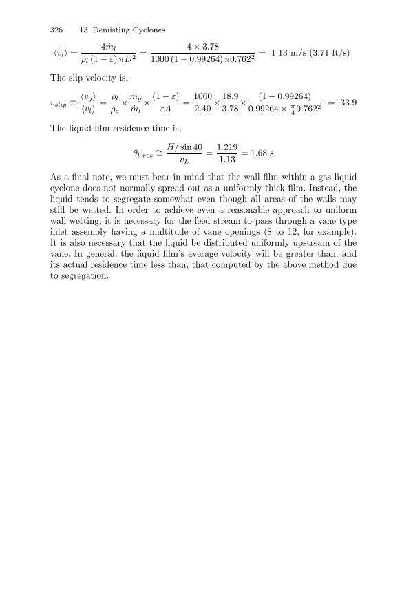
326 13 Demisting Cyclones
〈vl〉 =4ml
ρl (1 − ε)πD2=
4 × 3.781000 (1 − 0.99264)π0.7622
= 1.13 m/s (3.71 ft/s)
The slip velocity is,
vslip ≡ 〈vg〉〈vl〉 =
ρl
ρg× mg
ml× (1 − ε)
εA=
10002.40
× 18.93.78
× (1 − 0.99264)0.99264× π
4 0.7622= 33.9
The liquid film residence time is,
θl res∼= H/ sin 40
vL=
1.2191.13
= 1.68 s
As a final note, we must bear in mind that the wall film within a gas-liquidcyclone does not normally spread out as a uniformly thick film. Instead, theliquid tends to segregate somewhat even though all areas of the walls maystill be wetted. In order to achieve even a reasonable approach to uniformwall wetting, it is necessary for the feed stream to pass through a vane typeinlet assembly having a multitude of vane openings (8 to 12, for example).It is also necessary that the liquid be distributed uniformly upstream of thevane. In general, the liquid film’s average velocity will be greater than, andits actual residence time less than, that computed by the above method dueto segregation.