Embed Size (px)
Citation preview
12TH INTERNATIONAL
BRICK/BLOCK Masonry c O N F E R E N C E
Shi
A COMPARISON BETWEEN AUSTRAlIAN STANDARDS AND CHINESE CODES IN EARTHQUAKE-RESISTANT DESIGN OF
MASONRY STRUCTURES
Ling Shj1 and Yan lhuge2
'Lecturer, School of Architectural Engineering, North China University of Technology,
Beijing, 100041 ,China.
' Senior Lecturer, School of Engineering, University of South Australia,
Adelaide, SA5095, Australia
ABSTRACT
A detailed comparison between Australian Standards and Chinese Codes for earthquake-resistant design of masonry structures is presented in this paper. The emphasis of the comparison has been placed on the general requirements of the masonry design, the calculation and distribution of seismic actions, the design for reinforced and unreinforced masonry structures and detailing for construction.
Key words: Masonry structure, earthquake-resistant design, Australian Standards, Chinese Codes, constructional measures, reinforced masonry structure, unreinforced masonry structure.
1667
1668
1. INTRODUCTION
Masonry structures are generally used as domestic housing and public building in both Australia and China. In the past, earthquakes have caused serious collapses of masonry structures due to the relatively low ductility of the material. At the same time, there has been significant loss of lives and property. Ali of the civil engineering professionals have recognized the importance of earthquake-resistant design of masonry structure. Design codes have been drawn up in many countries.
Earthquakes have occurred frequently in China, particularly in the southwest provinces. Much detailed data of earthquakes and experiences in earthquake-resistance design have been obtained from the past earthquakes and research . Since the Tangshan catastrophe in 1976, the earthquake-resistant design method in Chinese Codes has been improved extensively. Australia, on the other hand, had been recognized as a low risk region for earthquake for many years. Earthquake- resistant design of structures has become an important issue only after the Newcastle earthquake in 1989. The elaborated standard for earthquake-resistance design of structures (AS11 70.4, 1993) has been made in 1993.
In this paper, we try to make a detailed comparison between Chinese Codes and Australian Standards. Because there are so many differences, the comparison has been focused on severa I clauses that mainly related to earthquake-resistant design of masonry structures.
2.CALCULATION OF EARTHQUAKE ACTION
1. The total horizontal earthquake action
• Chinese Code (G8Jll -89)
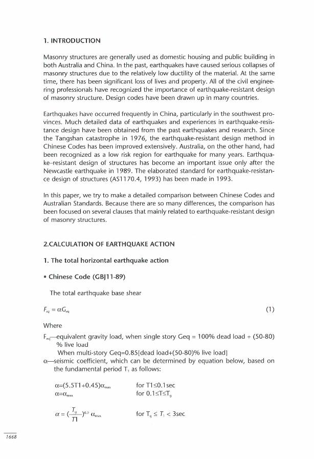
The total earthquake base shear
(1 )
Where
Feq-equivalent gravity load, when single story Geq = 100% dead load + (50-80) % live load When multi-story Geq=0.85[dead load+(50-80)% live load]
a- seismic coefficient, which can be determined by equation below, based on the fundamental period T, as follows:
a=(5 .5T1 +0.45)am"
T a = (_9_)09 a n max
for T1 :::;0.1 sec for 0.1 :::;T:::;T9
for T9 :::; T, < 3sec
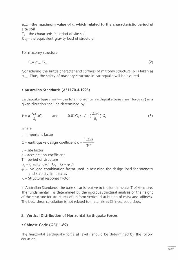
am .. -the maximum value of a which related to the characteristic period of site soil Tg-the characteristic period of site soil Geq-the equivalent gravity load of structure
For masonry structure
(2)
Considering the brittle character and stiffness of masonry structure, a is taken as a m.,. Thus, the safety of masonry structure in earthquake will be assured.
• Australian Standards (AS 1170.4-1993)
Earthquake base shear- the total horizontal earthquake base shear force (V) in a given direction shall be determined by
v = I( CS )G R 9
f
and
where
I - important factor 1.25a
C - earthquake design coefficient c = -T 3 Z
S - site factor a - acceleration coefficient T - period of structure Gg - gravity load Gg = G + <P cQ
(3)
<Pc - live load combination factor used in assessing the design load for strengtn and stability limit states
R, - Structural response factor
In Australian Standards, the base shear is relative to the fundamental T of structure. The fundamental T is determined by the rigorous structural analysis or the height of the structure for structures of uniform vertical distribution of mass and stiffness. The base shear calculation is not related to materiais as Chinese code does.
2. Vertical Distribution of Horizontal Earthquake Forces
• Chinese Code (GBJl1-89)
The horizontal earthquake force at levei i should be determined by the follow equation :
7669

1670
G; H; Fi = ---=n- -- Feq
L Gj Hj j = 1
where
F,--the horizontal earthquake action at leveis i n--the number of the leveis on structure Gi, G, gravity load at levei i H,--height above the structural base of the structure to levei i
• Australian standards (AS 1170.4-1993)
(4)
The horizontal earthquake force (Fx) applied at levei x shall be determined from the following equation:
where
Ggx h~ Cvx = - ---
± Gg;h\ i=1
Ggx-portion of gravity load (Gg) located or applied at levei x Gg,--portion of gravity load (Gg) located or applied at levei i hx-height above the structural base of the structure to leveis x n-number of leveis in structure k--an exponent dependent on the structure period (T), taken as-
(a) 1.0 when T::;0.5; or (b) 2.0 when T2:2.5 . (c) k may be linearly interpolated between 1.0 and 2.0 for 0.5<1<2.5.
(5)
The major difference between two codes is the "k" factor in Austral ian Standard. In Australian Standard, the vertical distribution of earthquake force has beaen affected by the period of structure. This has not been considered in Chinese Code.
2. MEMBER DESIGN FOR MASONRY STRUCTURES
1. Reinforced masonry structure
There is a detailed definition about reinforced masonry in Australian Standard (AS3700-1998), which mainly included the requirements for main reinforcement, secondary reinforcement and close-spaced reinforcement for increased ductility in earthquakes. While in Chinese Code (GBJ3-88), the concept of reinforced ma-

sonry is different. There are two kinds of reinforced masonry in Chinese Code, masonry with reinforced net (see Fig .1) and composite masonry (see Fig.2).
Figure 7. Masonry with Reinforcement Net.
WaIl
-4
/ Masonry
P' /
I ~
---;r-
I I I
So ~ 400
I I I
-'--
I 1---~ I
I I /
Figure 2. Composed Masonry Member.
h
b
I ~
C oncrete or Mortar
COJlstruc1ÍG:na) colum Jl
~ I
Secondary Reinforcement
Main Reinforcement
Reinforcement Net
30 ~.~ 120
I~ b ~ I
Concrete or Mortar
-·0
osed Secôon
In Australian Standard (AS3700-1998), the clause for members subject to compression, bending, shear, tension, combined bending and tension, combined bending and compression are specified. As for the design of members in shear
1671

7672
which is closely related to the earthquake-resistant capacity of structure, in-plane shear and out-of-plane shear are considered . An important influential factor for the in-plane shear capacity of member is H/L. At the same time, there is a strict requirement for the reinforcement layout. The reinforcement shall comply with the following:
(i) The reinforcement shall be located symmetrically in the cross section.
(i i) Vertical reinforcement shall be spaced at centers not exceeding 0.75H and in any case not greater than 2000 mm horizontally. Horizontal reinforcement shall be spaced at centers not exceeding 0.75+ and in any case not greater than 3000 mm vertically.
(iii) The vertical reinforcement shall be such that As~0.0013Ad and the horizontal reinforcement is such that As~0 .0007Ad ' If the reinforcement does not meet these requirements then the wall shall be designed in accordance with Clause 7.6.3 (that is designed as unreinforced masonry).
(iv) Reinforcement with an area of at least 100 mm2 shall be included within 300mm of edges parallel to the main reinforcement. It shall be permissible to omit the reinforcement at an edge of the wall, provided the member is anchored to an abutting reinforced concrete member.
where A,-the cross-sectional area of reinforcement
A,,--the design cross-section area of member
In Chinese Code (GBJ3-88), the reinforcement is used to enhance the compression capacity of brick masonry member when the capacity is not sufficient. Only the design of compression, combined compression and bending are considered. The fu rther quantitative analysis should be proposed in the future .
2. Unreinforced masonry structure
For unreinforced masonry structure, the consideration and calculation in bending, compression, shear and tension are similar to each other in both Australian Standards (AS3700-1998) and Chinese Code (GBJ3-89). The calculating process is more elaborate in Australian Standard. While in Chinese Code, the constructional measures are essential, especially the requirements for reinforced concrete ring beam and constructiona l column which will be specified in next section. There is no rei ative clause in Australian Standard.
3. CONSTRUCTIONAL MEASURES IN CHINESE CODES (GBJ3-88, GBJl1-89)
Construction measures are very important to the Chinese codes. Whether unreinforced masonry or reinforced masonry structure, the constructional measures

are compulsory. The measures are based on the research and experience that obtained from past earthquakes. The measures have been proved effective in minimizing earthquake damage. Two major parts are included in constructional measures, the basic design requirements and construction detailing.
1. The basic design requirements
a). The limitations of building height and story number, Table 1;
b). The limitation of height/width ratio, Table 2; The clauses (a) and (b) are the basic requirements for overall layout of masonry structure.
c). The spacing limitation between transverse structural walls, Table 3; This clause is used to ensure the shear capacity and integrity of masonry structure under horizontal force.
Table 7. Limitations of Heights for Masonry Buildings.
Minimum Intensity
Type Thickness
oi masonry olwali (mm) V VII VIII IX
H n H n H n H n (m) (m) (m) (m)
(Iay brick 240 24 8 21 7 18 6 12 4
Small size 190 21 7 18 6 15 5 Should concrete block not be
Medium size 200 18 6 15 5 9 3 used concrete block
• H-the height oi building; n-the number oi stories oi building.
Table 2. Maximum Height/Width Ratio.
Seismic intensity VI VII VIII IX
(H /W)max 2.5 2.5 2.0 1.5
Table 3. The Maximum Spacing of Transverse Shear Walls (m).
Clay brick building Medium-size block Small-size block Type of
building building floor
and roof Seismic intensity
VI VII VIII IX VI VII VIII VI VII VIII
Cast in-situ
and monolithic 18 18 15 11 13 13 10 15 15 11
pre-cast
R.C
1673

1674
Table 4. Local dimension limitations (m).
Seismic intensity
Location VI VII VIII IX
Minimum width 01 a bearing wall between windows 1.0 1.0 1.2 1.5
Minimum distance l rom the end 01 exterior bearing wall to edge 01 doar ar window opening 1.0 1.0 1.5 2.0
Minimum distance lrom the end 01 non-exterior bearing wall to edge 01 doar ar window opening 1.0 1.0 1.0 1.0
Minimum distance lrom the outside corner 01 interior wall to edge 01 doar ar window opening 1.0 1.0 1.5 2.0
Maximum height of parapet without anchorage 0.5 0.5 0.5 O
d) Local dimension limitations of multi-story buildings, Table 4; This clause is used to prevent local failure of masonry structure under earthquakes.
2. Constructional detailing
Construction detailing mainly includes requirements for the layouts of cast in-situ concrete columns and ring beams (see Fig.3). They have been proved by research and earthquake experience to be effective in preventing the development of crack and collapse of the structure. These requirements are adapted to both reinforced and unreinforced masonry structures. The function of constructional column and ring beam is confining the masonry wall. Thus it increases the shear capacity and puts off the fa ilure of masonry wall.
Figure 3. Constructional column and ring Beam in Maronry.
Á
~ Ir @-EJ "f'
r-
Masonry ®., '1
/ -:~ ? li
onstructiDnal Cohunn. ~,
@_. "f' I I -''-
I i <D @
r i i
CD l- I
0 -a). Requirements for the layout of cast in-situ constructional columns
Requirements for clay brick masonry, Table 5; Requirements for concrete block masonry, Table 6;
Ring BeaJll

b). Requirements for the layout of cast in-situ constructional ring beams Requirements for day brick masonry, Table 7, 8;
Table 5. Requirements of Constructional Columns for C/ay Masonry.
Stories 01 building For ali buildings Location 01 the columns
VI VII VIII IX
4,5 3,4 2,3 At the lour corners 01 ali stairs and lilts lor VII, VIII.
Four corners 01 At the connection between transverse walls exterior wall, two and exterior walls lor every two spans and
6-8 5-6 4 2 sides 01 bigger at the lour corners 01 ali stairs and lilts, holes, the 10rVII to IX. connections between interior At connections between interior walls and and exterior walls exterior walls, the shorter interior wall, the
7 5,6 3,4 lor large rooms. lour corners 01 stairs and lilts lor VII to IX; at the connection between an interior longitudinal wall and a transverse wall lor IX.
'lhe minimum section area 01 column is 240mmx240mm; lhe minimum main reinlorcement is 4$12.
Table 6. Core reinforcement of columns for concrete block masonry.
Number 01 stories Location 01 the core reinlorcement column
VI VII VIII
4,5 3,4 2,3 lhe lour corners 01 exterior wall and stairs, the connection between interior wall and exterior walls 01 large rooms.
lhe same as above, the connections between transverse walls and interior 6 5 4 longitudinal walls, interior transverse walls and exterior longitudinal walls lor
every two spans.
lhe same as above, the connection between interior walls and exterior walls, 7 6 5 the connections between interior longitudinal and interior transverse walls and
two sides 01 door.
'lhe minimum section area 01 core column is 1 30mmx 1 30mm.
Table 7. Ring Beams for C/ay Masonry.
Style 01 wall Intensity
VI VII VIII
Exterior wall and interior Rool and Iloors lor every Rool and every Iloor Rool and every Iloor longitudinal two stories
wall
lhe same as above; lor lhe same as above; ali the lhe same as above, ali rool, the spacing should be transverse walls spacing the transverse walls 01
Interior less than 7m; lor Iloor, the should be less than 7m and every story. transverse spacing should be less than at the same location 01
wall 15m and at the same constructional columns location 01 constructional column
'lhe minimum height 01 ring beam is 120mm.
1675

1676
Table 8. Minimum Reinforcement in Ring Beam.
Intensity
Style of reinforcement VI, VII VIII IX
Maximum space of stirrup 250 200 150
Minimum main reinforcement 4<1>8 4<1>10 4<1>12
Requirements for concrete block masonry: Ring beams constructed of concrete blocks should be laid out according to the requirements of an intensity grade, one grade higher than that for clay masonry.
4. SUMMARY AND CONCLUSIONS
By comparing, it has been found that the basic considerations of earthquake design are similar between Australian Standards and Chinese Codes, although there are some different coefficients and formulae in design processo
By contrasting, two major differences between Chinese codes and Austral ian standards have been found. Firstly, constructional measures are strongly emphasized in Chinese codes for the design of masonry structure. These measures have been proved very effective by the past earthquakes and research. There are no corresponded clauses in Australian Standards. Secondly, there are more specified clauses for member design in Australian Standards than in Chinese codes.
REFERENCES:
1. ASl170-1993, Australian Standards, "Minimum design loads on structures";
2. AS3700-1998, Australian Standard, " Masonry Structures";
3.GBJll-89 National standard of P.R. China; "Earthquake-resistance Design Code of Building";
4. GBJ3-88, National standard of P.R. China; "Masonry Structure Design Code" .
5. JGJ14-82, National standard of P.R. China, "Design and Constructional Regulation of Concrete Block Masonry";