Embed Size (px)
Citation preview

1 - Spedo 2300 Operators Manual Spedo UK Limited
� ������������ ��������
OPERATORS MANUAL
Issue 1 Part Number SP006 104
Unit 5 Riverwey Ind. Park
Newman Lane, Alton Hampshire GU34 2QL
ENGLAND
Telephone National: 01420 86546 International: +44 1420 86546 Facsimile National: 01420 89892 International: +44 1420 89892
Spedo 2300 Forms Cutter Manual on CD Part Number 006 104
2 - Spedo 2300 Operators Manual Spedo UK Limited
� ������������ ��������
�� �����������
�������� ��� ����� ������ ��������������
1 January 2007 First Edition

Spedo 2300 Forms Cutter Manual on CD Part Number 006 104
3 - Spedo 2300 Operators Manual Spedo UK Limited
� ������������ ��������
����������Published by Spedo UK Limited
Unit 5, Riverwey Ind. park Newman Lane
Alton, Hampshire GU34 2QL
ENGLAND
����������Spedo UK Limited 2007
��������� ��� ����� �No part of this publication may be reproduced, stored in a retrieval system, or transmitted, in any form or by any means, electronic, mechanical, photocopying, recording, or otherwise, without the prior written permission of Spedo UK Limited.
!����"�Unpack the equipment and examine it thoroughly to ascertain whether any damage has occurred in transit. Report immediately any such damage to the agent or manufacturer. Retain the packing should further transportation be necessary.
����#��� �All goods manufactured by the Company are guaranteed to the extent hereafter mentioned against defects arising from faulty material or workmanship subject to the goods not having suffered maltreatment or interference. The Company's liability under this guarantee is limited to replacing any part or parts found defective within a period as laid down in Company instructions after the date of delivery or installation.
$�����#��� �If goods not of the Company's manufacture are ordered, the guarantee of that company is to be accepted.
�� ����������������Descriptive matter, illustrations, dimensions and weights issued by the Company are typical and shall not be held as binding.
%������ ������� ��� �The Company reserves the right to alter patterns and designs without notice.
�� ��%�&�� �����'��������(�
We have taken every care in the preparation of this manual. If there are any inaccuracies, ambiguities or omissions, Spedo UK Limited and its consultants and distributors cannot accept responsibility for any loss or damage these errors may cause.

Spedo 2300 Forms Cutter Manual on CD Part Number 006 104
4 - Spedo 2300 Operators Manual Spedo UK Limited
� ������������ ��������
�
�
�
�
��)������� ��� �
This instruction manual contains certain WARNING and CAUTION notices which must be followed by the user to ensure safe operation and to retain the equipment in a SAFE condition. All users of the equipment described in this manual MUST have received adequate training in its use and application in order to ensure SAFE AND PROPER USE. Any adjustment, maintenance or repair of the opened apparatus under voltage shall be carried out only by a skilled person who is AWARE OF THE HAZARD INVOLVED.

Spedo 2300 Forms Cutter Manual on CD Part Number 006 104
5 - Spedo 2300 Operators Manual Spedo UK Limited
� ������������ ��������
*�&����)�������� �
History Sheet .............................................................................................................. 2 Copyright.................................................................................................................... 3 Safety Measures.......................................................................................................... 4 Table of Contents........................................................................................................ 5
#+,+��-��+����%*�$,� �+�*�$,�.�
INTRODUCTION.................................................................................................. 7 TECHNICAL DATA ............................................................................................. 8 DESCRIPTION OF OPERATION......................................................................... 9
Spedo 2300 Forms Cutter .................................................................................. 9 Operation with Web Control Units 970/971 ..................................................... 10 Operation with a Printer or Collator ................................................................. 10
MODES OF CUT................................................................................................. 11 Introduction ..................................................................................................... 11 Setting the Form Depth.................................................................................... 12 Setting the Strip Depth in Dual Cut Mode........................................................ 17
APPENDIX A1 Optional Accessories .................................................................. 19 APPENDIX A2 Residual Current Device............................................................. 20
�$������$,�,#�*�+��/�*+�� �+�*�$,���
INTRODUCTION................................................................................................ 21 UNPACK............................................................................................................. 21 ACCESSORIES................................................................................................... 21 SITE CONSIDERATIONS .................................................................................. 21 INSTALLATION................................................................................................. 21
Connecting the Mains (Power) Lead ................................................................ 21 Installation Checks .......................................................................................... 21 USE OF RESIDUAL CURRENT DEVICE (RCD).......................................... 23
$%+��*�,#��,�*�!�*�$,�� �+�*�$,���
SUMMARY OF CONTROLS.............................................................................. 25 Paper Transport deck ....................................................................................... 25 Control Panel................................................................................................... 25
OPERATING PROCEDURE............................................................................... 25 Summary of Controls - Pushbuttons ............................................................ 25 Summary of Controls - Batch Counter......................................................... 27
Setting the Counter .......................................................................................... 28 Standard & Enhanced Mode Selection ............................................................. 29 Enhanced Mode - Edit Sequence...................................................................... 30 Enhanced Mode - Job Definition Sequence...................................................... 31 WARNINGS ................................................................................................... 32 Paper Loading.................................................................................................. 32 Operation from the Control Panel .................................................................... 33
Preliminary Manual Cut Operation.............................................................. 33 Setting Side Trimmers & (Optional) Centre Cutter ...................................... 34 No-Cut Operation........................................................................................ 35
Spedo 2300 Forms Cutter Manual on CD Part Number 006 104
6 - Spedo 2300 Operators Manual Spedo UK Limited
Start Continuous Operation ......................................................................... 35 Stop Continuous Operation ......................................................................... 35 Emergency Stop Operation.......................................................................... 35 Paper Run-out ............................................................................................. 36
$%+��*�$,�-����,*+,�,�+� �+�*�$,�0�
WARNINGS........................................................................................................ 37 CLEANING......................................................................................................... 37 LUBRICATION................................................................................................... 37 WARNING: Lithium Batteries ............................................................................. 37

Spedo 2300 Forms Cutter Manual on CD Part Number 006 104
7 - Spedo 2300 Operators Manual Spedo UK Limited
#+,+��-��+����%*�$,�� �+�*�$,�.�
�,*�$�!�*�$, The Spedo 2300 Forms Cutter is designed to produce cut sheets from single or multiple continuous paper webs. In addition, the machine can also optionally trim away either or both carrier strips and optionally centre cut the paper web.
Fig 1.1 Spedo 2300 Forms Cutter A normal cross-cut is made at the perforation line across the paper web. However, the machine is also capable of operating in double cross-cut mode, when it is required to cut before and after the perforation (so removing the perforation).
The depth of form to be cut, depth of strip and feed are all measured in terms of line increments, either as a 6 lines per inch, 8 lines per inch, 10 lines per inch, 12 lines per inch or 16 lines per inch. In double cut mode, a second cross-cut is made at any interval of between 1 to 9 lines after the first cut as set by the digital coding switch.
Spedo 2300 Forms Cutter Manual on CD Part Number 006 104
8 - Spedo 2300 Operators Manual Spedo UK Limited
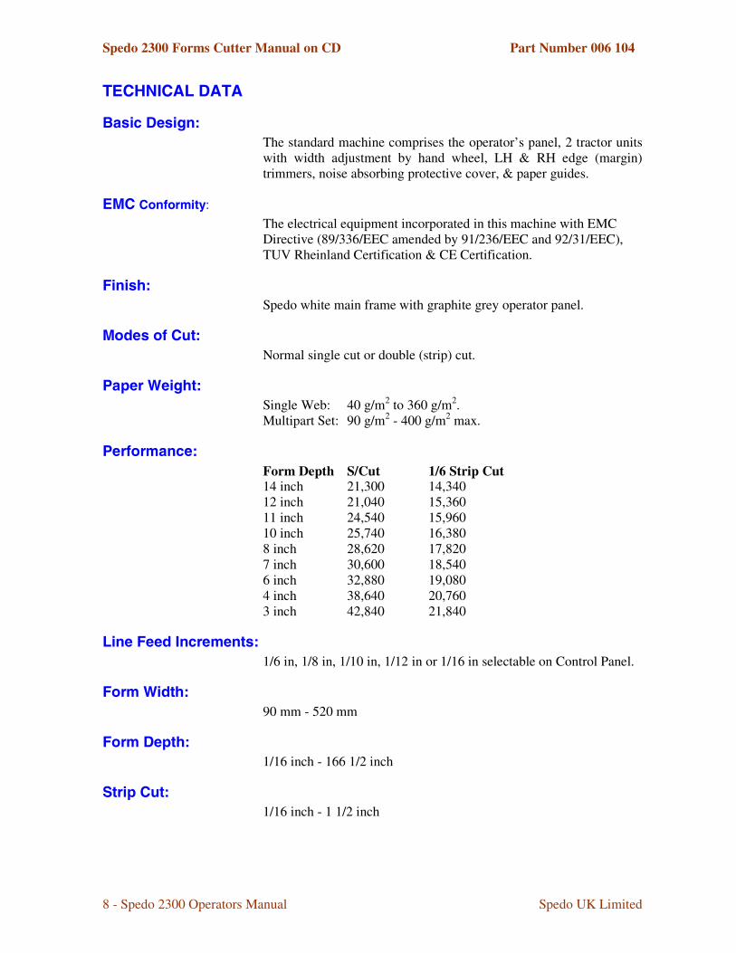
*+��,���-���*��
1� ����� ���2�
The standard machine comprises the operator’s panel, 2 tractor units with width adjustment by hand wheel, LH & RH edge (margin) trimmers, noise absorbing protective cover, & paper guides.
+������)��������
The electrical equipment incorporated in this machine with EMC Directive (89/336/EEC amended by 91/236/EEC and 92/31/EEC), TUV Rheinland Certification & CE Certification.
��� �2�
Spedo white main frame with graphite grey operator panel.
���� ��)����2�
Normal single cut or double (strip) cut.
%�����3�����2�
Single Web: 40 g/m2 to 360 g/m2. Multipart Set: 90 g/m2 - 400 g/m2 max.
%��)�������2�
Form Depth S/Cut 1/6 Strip Cut 14 inch 21,300 14,340 12 inch 21,040 15,360 11 inch 24,540 15,960 10 inch 25,740 16,380 8 inch 28,620 17,820 7 inch 30,600 18,540 6 inch 32,880 19,080 4 inch 38,640 20,760 3 inch 42,840 21,840
-����������������� 2�
1/6 in, 1/8 in, 1/10 in, 1/12 in or 1/16 in selectable on Control Panel.
����3����2�
90 mm - 520 mm
���������2�
1/16 inch - 166 1/2 inch
���������2�
1/16 inch - 1 1/2 inch

Spedo 2300 Forms Cutter Manual on CD Part Number 006 104
9 - Spedo 2300 Operators Manual Spedo UK Limited
3������)���������� �3�&2�
With carrier strip: 475 mm Without carrier strip: 510 mm
���������2�
Rotary control, continuously adjustable.
��������*���2�
Up/Down Counter, provided for use as a batch counter.
%�4�����5�������� 2�
Voltage: 230 V +/-10% Frequency: 50 Hz to 60 Hz. Power Consumption: 690 W (approx).
����� ��� 2�
Length: 550 mm. Width: 980 mm. Height: 1070 mm.
3�����2�
140 kg (approx).
$����� �
Options are listed in Appendix A1 to this section.
�+����%*�$,�$�$%+��*�$,�
������������ ��������
Paper is fed into the machine under the paper tension brush, over the in-feed plate, along the paper supports onto two tractor units. Once the tractor units have been adjusted for width and thickness (weight) of paper web, the web is `jogged' forward and backwards by the operator until it has been aligned with the datum marks on the tractor unit flaps.
At this stage, if the carrier sides (margins) are to be cut off, LH and RH trimmers can be engaged, their precise position being set by aligning their cut marks with the carrier perforations. In addition, a centre cutter can be engaged and aligned by the operator at this point, if required.
The machine is capable of operating in conjunction with an ancillary unit (e.g. a web control, printer or collator) and successful co-operation between the two units depends on the loop of paper that forms between the two machines. The presence of paper feeding into the machine is detected by a paper runout switch located on the in-feed plate. If the paper runs out, the machine automatically stops.

Spedo 2300 Forms Cutter Manual on CD Part Number 006 104
10 - Spedo 2300 Operators Manual Spedo UK Limited
$���������4����������3�&���������!��� �6(76(.�
When the machine is being supplied from a web control unit, and the in-fed paper is applied, a loop of paper forms between (Fig 2.1). The machine always controls its in-feed of paper from the web control. When the loop is low enough for the proximity sensor on the web control unit to detect its presence the web control unit is held stopped.
Fig 1.2 Loop Control - Web Control Units 970 & 971 As the machine continues to demand paper, the loop starts to rise. As the loop rises the photo cell on the web control unit will be cleared and the web control unit will start up until the loop falls far enough for the photo cell to detect it and so stop again. Note that the machine should always be set to run slower than the web control unit to maintain the loop.
Fig 1.3 Loop Control – Optical Loop Switch unit
$���������4������%�������������������
When the machine is being supplied from a printer or collator which has no means of controlling its out-feed, it will be necessary to control the paper loop height by positioning either a Spedo Optical Loop Switch Unit or an Optical Loop Interface Unit between the machine and the printer or collator as shown in Figs 1.3 & 1.4. Both Optical Loop units are available from Spedo UK Ltd.
2300
2300
The loop must stay within both sensors. If both sensors are uncovered, the 2300 stops and the 970/971 runs. If the top sensor is covered and the bottom sensor is not covered, both units run. If both sensors are covered, the 2300 runs and the 970/971 stops.
2300 RUNS
Spedo 2300 Forms Cutter Manual on CD Part Number 006 104
11 - Spedo 2300 Operators Manual Spedo UK Limited
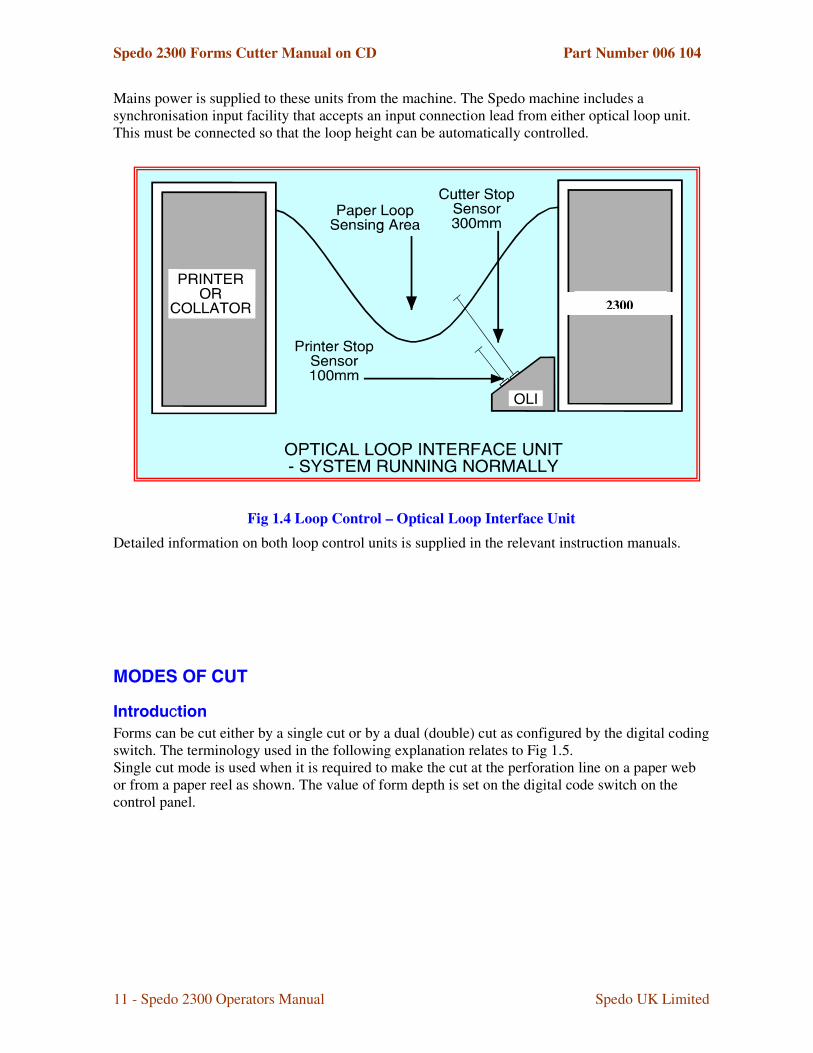
Mains power is supplied to these units from the machine. The Spedo machine includes a synchronisation input facility that accepts an input connection lead from either optical loop unit. This must be connected so that the loop height can be automatically controlled.
Fig 1.4 Loop Control – Optical Loop Interface Unit
Detailed information on both loop control units is supplied in the relevant instruction manuals.
�$�+��$��!*�
�������������
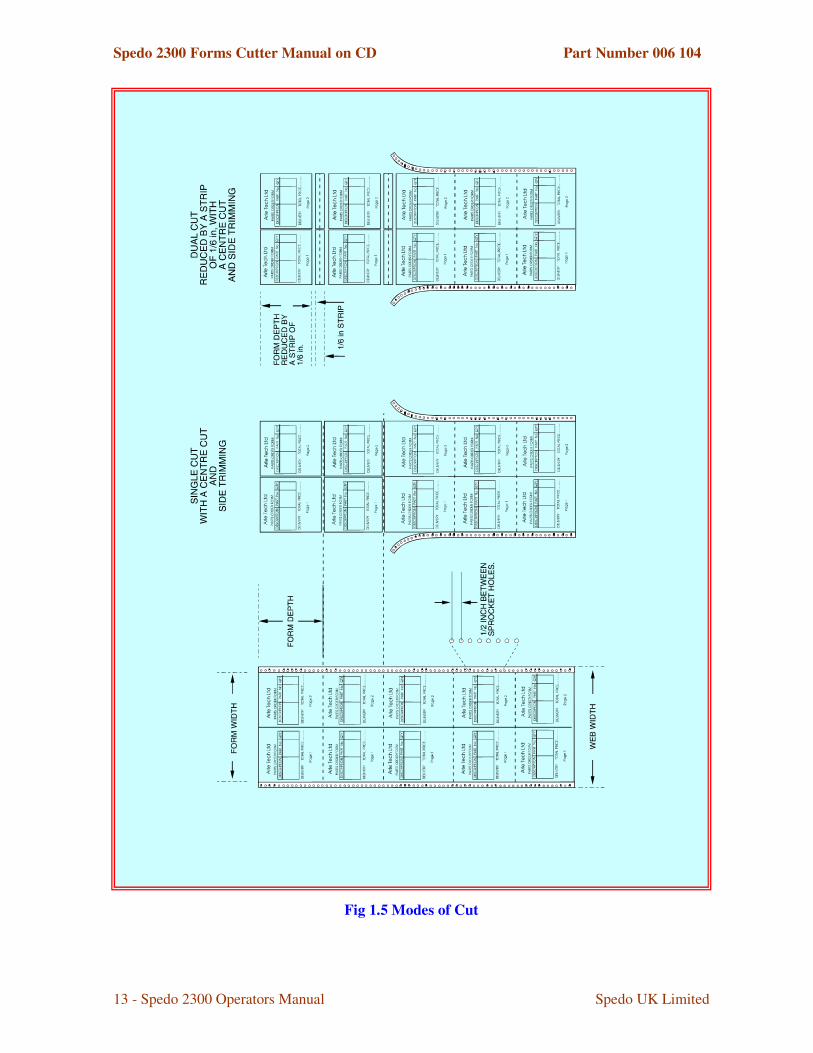
Forms can be cut either by a single cut or by a dual (double) cut as configured by the digital coding switch. The terminology used in the following explanation relates to Fig 1.5. Single cut mode is used when it is required to make the cut at the perforation line on a paper web or from a paper reel as shown. The value of form depth is set on the digital code switch on the control panel.
2300

Spedo 2300 Forms Cutter Manual on CD Part Number 006 104
12 - Spedo 2300 Operators Manual Spedo UK Limited
Dual cut mode is used when the cut form depth required is smaller than the depth between perforations or when it is just required to cut out the perforation lines as shown below.
Modes of Cut – Single Cut As can be seen, this results in a strip being cut away between forms. In this mode, the value of the form depth and the strip depth is set in on the digital code switch on the control panel.
����������������������
The principle of setting form depth is by line count. The machine motor is geared such that 1 revolution of the tractor belt moves the paper web forward exactly 6 inches.
Modes of Cut – Dual Cut
Spedo 2300 Forms Cutter Manual on CD Part Number 006 104
13 - Spedo 2300 Operators Manual Spedo UK Limited
Fig 1.5 Modes of Cut
Spedo 2300 Forms Cutter Manual on CD Part Number 006 104
14 - Spedo 2300 Operators Manual Spedo UK Limited
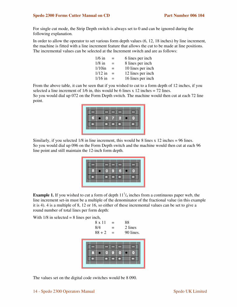
For single cut mode, the Strip Depth switch is always set to 0 and can be ignored during the following explanation.
In order to allow the operator to set various form depth values (6, 12, 18 inches) by line increment, the machine is fitted with a line increment feature that allows the cut to be made at line positions. The incremental values can be selected at the Increment switch and are as follows:
1/6 in = 6 lines per inch 1/8 in = 8 lines per inch 1/10in = 10 lines per inch 1/12 in = 12 lines per inch 1/16 in = 16 lines per inch
From the above table, it can be seen that if you wished to cut to a form depth of 12 inches, if you selected a line increment of 1/6 in, this would be 6 lines x 12 inches = 72 lines. So you would dial up 072 on the Form Depth switch. The machine would then cut at each 72 line point.
Similarly, if you selected 1/8 in line increment, this would be 8 lines x 12 inches = 96 lines. So you would dial up 096 on the Form Depth switch and the machine would then cut at each 96 line point and still maintain the 12-inch form depth.
Example 1. If you wished to cut a form of depth 111/4 inches from a continuous paper web, the line increment set-in must be a multiple of the denominator of the fractional value (in this example it is 4). 4 is a multiple of 8, 12 or 16, so either of these incremental values can be set to give a round number of total lines per form depth:
With 1/8 in selected = 8 lines per inch, 8 x 11 = 88 8/4 = 2 lines 88 + 2 = 90 lines.
The values set on the digital code switches would be 8 090.
Spedo 2300 Forms Cutter Manual on CD Part Number 006 104
15 - Spedo 2300 Operators Manual Spedo UK Limited
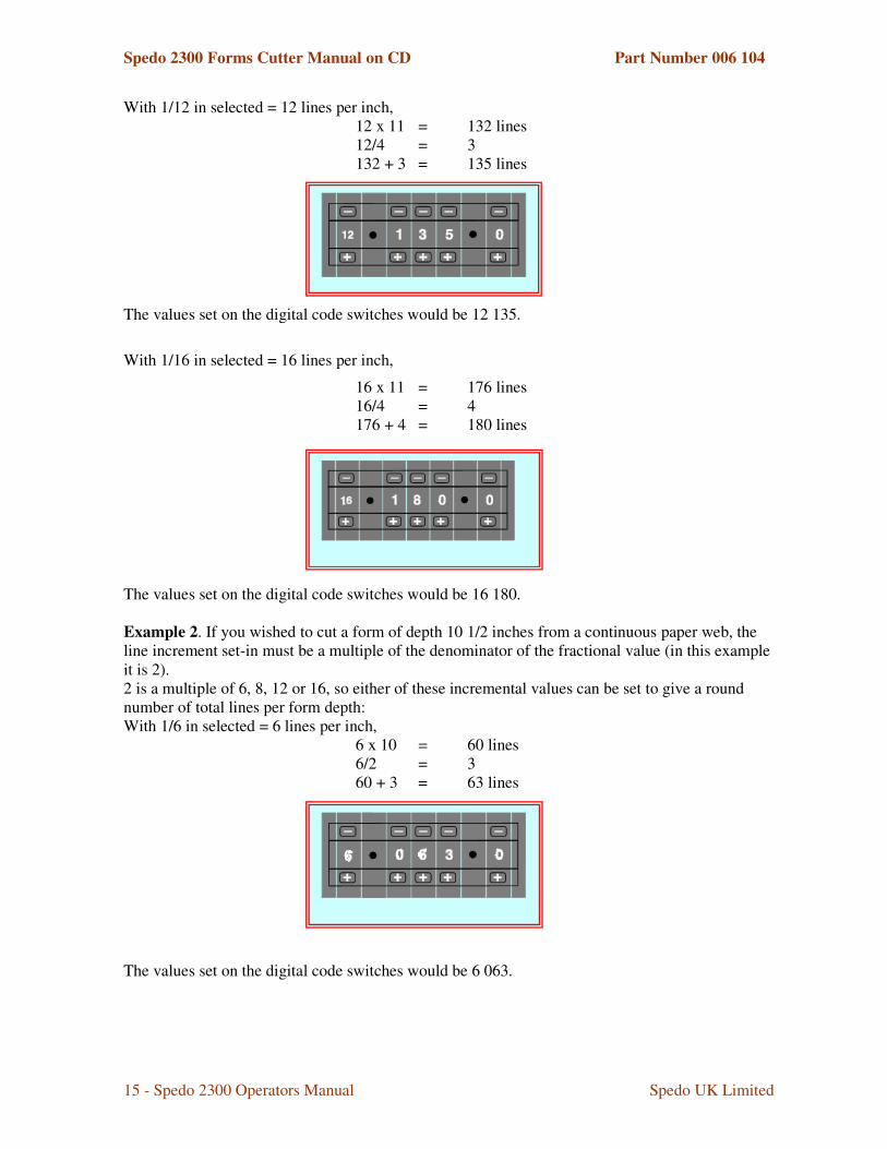
With 1/12 in selected = 12 lines per inch, 12 x 11 = 132 lines 12/4 = 3 132 + 3 = 135 lines
The values set on the digital code switches would be 12 135.
With 1/16 in selected = 16 lines per inch,
16 x 11 = 176 lines 16/4 = 4 176 + 4 = 180 lines
The values set on the digital code switches would be 16 180. Example 2. If you wished to cut a form of depth 10 1/2 inches from a continuous paper web, the line increment set-in must be a multiple of the denominator of the fractional value (in this example it is 2). 2 is a multiple of 6, 8, 12 or 16, so either of these incremental values can be set to give a round number of total lines per form depth: With 1/6 in selected = 6 lines per inch,
6 x 10 = 60 lines 6/2 = 3 60 + 3 = 63 lines
The values set on the digital code switches would be 6 063.

Spedo 2300 Forms Cutter Manual on CD Part Number 006 104
16 - Spedo 2300 Operators Manual Spedo UK Limited
With 1/8 in selected = 8 lines per inch,
8 x 10 = 80 lines 8/2 = 4 80 + 4 = 84 lines.
The values set on the digital code switches would be 8 084.
With 1/10 in selected = 10 lines per inch,
10 x 10 = 100 lines 10/2 = 5 100 + 5 = 105 lines.
The values set on the digital code switches would be 10 105. With 1/12 in selected = 12 lines per inch,
12 x 10 = 120 12/2 = 6 120 + 6 = 126 lines.
The values set on the digital code switches would be 12 126. With 1/16 in selected = 16 lines per inch,
16 x 10 = 160 lines 16/2 = 8 160 + 8 = 168 lines.
The values set on the digital code switches would be 16 168.

Spedo 2300 Forms Cutter Manual on CD Part Number 006 104
17 - Spedo 2300 Operators Manual Spedo UK Limited
Example 3. If you wished to cut a form of depth 7 1/5 inches from a 12-inch continuous paper web, the line increment set-in must be a multiple of the denominator of the fractional value (in this example it is 5).
5 is a multiple of 10, so only an incremental value of 10 can be set to give a round number of total lines per form depth:
With 1/10 in selected = 10 lines per inch,
10 x 7 = 70 lines 10/5 = 2 70 + 2 = 72 lines.
The values set on the digital code switches would be 10 072.
�����������������������������������������
When in dual cut mode, the machine makes a cut immediately before and after a perforation, resulting in a strip being cut out. The strip depth value is set in terms of line increment on the Strip Depth switch.
Consider Example 1 again. A form depth of 11 1/4 is to be cut from a 12-inch web:
12 - 11 1/4 = 3/4.
This means that a 3/4 inch strip must be cut out between forms. A 3/4 inch depth at a line increment of 1/8 in works out as|:
8/4 = 2 2 x 3 = 6 lines.
Spedo 2300 Forms Cutter Manual on CD Part Number 006 104
18 - Spedo 2300 Operators Manual Spedo UK Limited
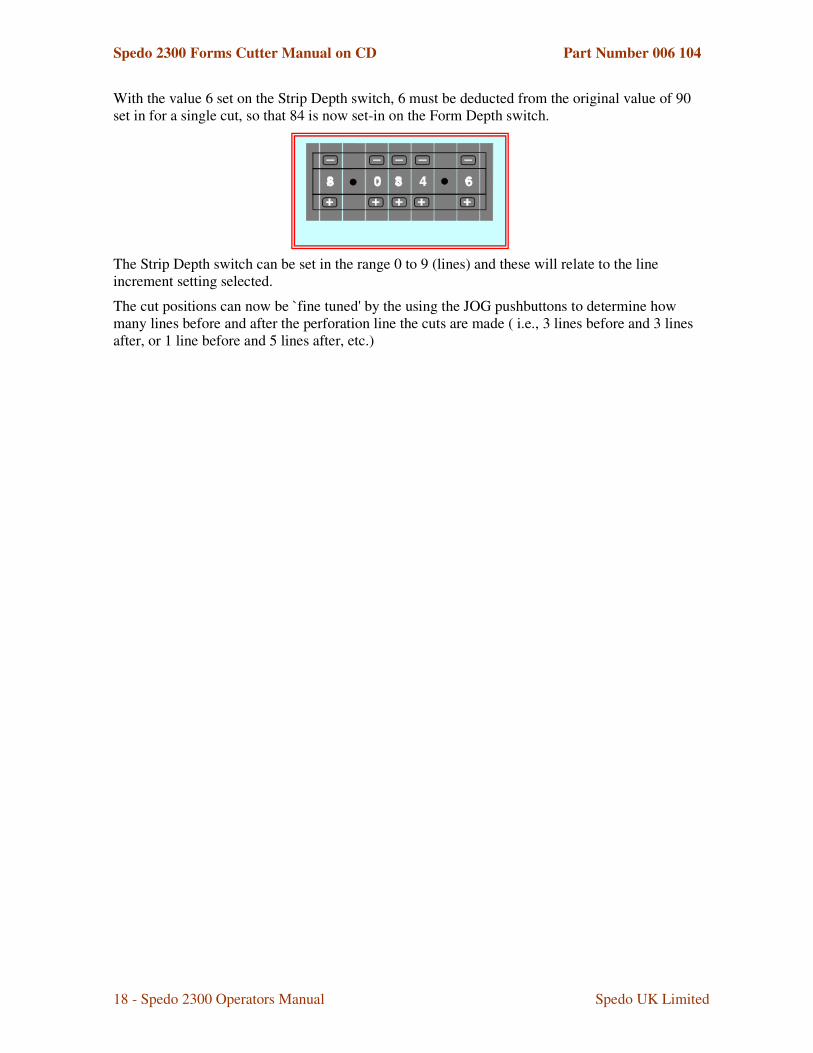
With the value 6 set on the Strip Depth switch, 6 must be deducted from the original value of 90 set in for a single cut, so that 84 is now set-in on the Form Depth switch.
The Strip Depth switch can be set in the range 0 to 9 (lines) and these will relate to the line increment setting selected.
The cut positions can now be `fine tuned' by the using the JOG pushbuttons to determine how many lines before and after the perforation line the cuts are made ( i.e., 3 lines before and 3 lines after, or 1 line before and 5 lines after, etc.)

Spedo 2300 Forms Cutter Manual on CD Part Number 006 104
19 - Spedo 2300 Operators Manual Spedo UK Limited
$%*�$,�-����+��$��+�� �%%+,��8��.�
���&������ 9����1�����
This is a cross-cutting device for removing the cross perforation from the paper web, without any loss of time or performance. The strip depth is 1/6 in and should be used with Conveyor Stacker Series 954. The strip is cleanly separated from the forms on each motion of the blades by blown air. The movable lower blade can be tilted off for single cut operation, if required. In this mode, the Strip Depth switch on the control panel can be used in the normal way.
$�������-�����4�����!��������
This unit is designed to control the height of the paper loop which forms between an outfeeding printer or collator and the associated in-feeding Spedo Forms Cutter.
$�������-���������)����!�������.�
This unit is designed to control the height of the paper loop that forms between an out-feeding printer or collator and the associated in-feeding Spedo Forms Cutter. It also detects the overflow of paper out-feeding from the printer or collator that occurs if the Forms Cutter stops accepting paper infeed.
3�&���������!��� �6(76(.�
These units are part web separators for sequencing pages.
�������������������
This is used for shredding the cut-off side strip which is collected in a metal tray.
$����������"�������������
It is intended that this option will be available for future use. It will be capable of the following explained system function. In any printing column, required control marks distributed on the form can be scanned. These marks make up a control code that determines how the form, carrying these marks, is to be processed. In this way forms can be assembled into groups, sorted and collected according to the address in system operation etc. Refer to the associated operators manual.
������������3� ���%����������������%.:�
This is supplied with mounting accessories for the side stripper chopper option.
������������� �
A Centre Cutter Assembly can be fitted, so providing additional longitudinal cuts along the paper web.
��������������� ���� �
� Automatic Waste Removal Unit 4100
� Stack Tray & Paper Stops
� 2 Bar Infeed Guide SP001 861 for web control.
� 3 Bar Infeed Guide SP001 846 for centre slit and merged forms
� Cut-Before-Feed Mode

Spedo 2300 Forms Cutter Manual on CD Part Number 006 104
20 - Spedo 2300 Operators Manual Spedo UK Limited
�+���!�-��!��+,*��+;��+� �%%+,��8����
!�+�$��+���!�-��!��+,*��+;��+�<���=�
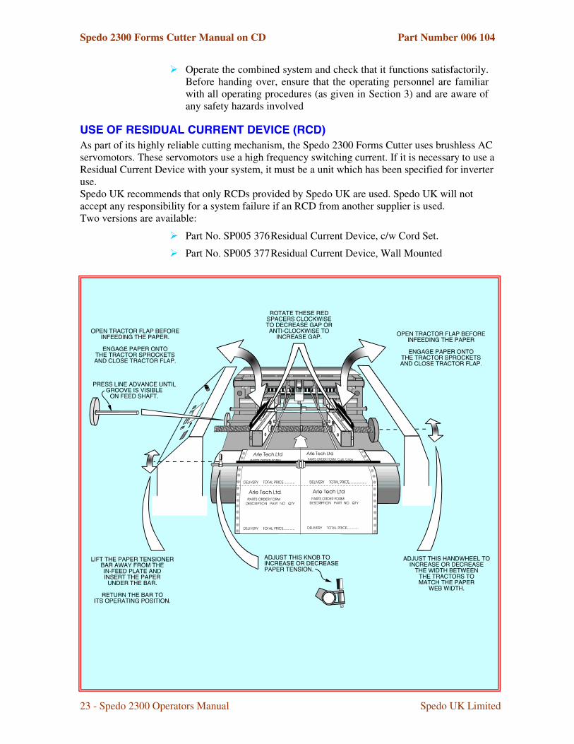
As part of its highly reliable cutting mechanism, the Spedo 2300 Forms Cutter uses brushless AC servomotors. These servomotors use a high frequency switching current. If it is necessary to use a Residual Current Device with your system, it must be a unit that has been specified for inverter use. Spedo UK recommends that only RCDs provided by Spedo UK are used. Spedo UK will not accept any responsibility for a system failure if an RCD from another supplier is used. Two versions are available:
� Part No. SP005 376 Residual Current Device, c/w Cord Set.
� Part No. SP005 377 Residual Current Device, Wall Mounted.

Spedo 2300 Forms Cutter Manual on CD Part Number 006 104
21 - Spedo 2300 Operators Manual Spedo UK Limited
�$������$,�,#�*�+��/�*+�� � � � ��+�*�$,���
�,*�$�!�*�$,�
The procedures given in this section should only be carried out by a competent trained service technician. Once the forms cutter has been declared ready to operate, the operating personnel should be made familiar with its safe operation.
!,%��>�
� Unpack the equipment and examine it thoroughly to ascertain whether any damage has occurred in transit.
� Report immediately any such damage to the agent or manufacturer. Retain the packing should further transportation be necessary.
���+��$��+��
The following items are supplied as standard:
� Operators Manual SP004 590
��*+��$,���+��*�$,��
For optimum use of the forms cutter with an ancillary unit, the distance between them should be at least 3 feet up to a maximum of 8 feet. If heavy weight paper is to be cut, the maximum possible distance should be allowed.
Consideration must also be given to the layout and positioning of work tables and cupboards surrounding working area, at the same time leaving enough space around the system for the operator to have access to all operational requirements.
The forms cutter should be set square in relation to any ancillary unit. If an ancillary unit is to be used with the forms cutter, refer to the relevant instruction manual, before making up the combined system.
�,�*�--�*�$,�
������������������� �<%�4��=�-����
Connect the power lead to a plug suitable for the local power source. The colour codes are as follows:
� L (live) = BROWN wire
� N (neutral) = BLUE wire
� E (earth / ground) = GREEN/YELLOW wire.
Connect the power lead into the local power source socket.
�� ��������������" �
WARNING: Never operate the forms cutter when wearing items of loose clothing or other decorative jewellery, such as necklaces or bracelets as they could become entrapped in the machinery and cause injury.

Spedo 2300 Forms Cutter Manual on CD Part Number 006 104
22 - Spedo 2300 Operators Manual Spedo UK Limited
� Note: If there is a delay of greater than 1 minute in moving between steps in the following procedure, the forms cutter goes into `sleep mode'. To return to normal operation, hold down the START button for at least 2 seconds.
� The first time that the cross-cutting blade is to be actuated, it must only be carried out manually by a Spedo trained technician.
� Connect the machine to the local mains supply. Switch ON and check that the STOP and START pushbuttons illuminate. Close the protective cover.
� Set the digital coding switch to 6 035 1. Press the START pushbutton once. The STOP pushbutton should extinguish.
� Press the Line Advance pushbutton, so that the feed shaft rotates until the groove on the shaft is clearly visible, as shown in Fig 2.1.
� Press the In Feed pushbutton 6 times and check that the feed shaft rotates 6 times, returning to its original position.
� Press the Manual Blade pushbutton and check that the blade motor fires once per press.
� Press the START pushbutton once. Check that the feed shaft rotates one complete revolution and that the blade motor fires twice (dual cut). Check that the feed shaft has returned to its original position.
� Hold down the START button and check that the machine runs continuously.
� Place a sheet of paper under the paper tension brush, so as to cover the paper run out switch.
� Press the Continuous pushbutton once. Check that it has locked in position and that it has illuminated.
� Press the START pushbutton once. Check that the machine now cycles continuously with the feed shaft rotating one complete revolution, returning to its start point ,and the blade firing twice (dual cut).
� Check that this cycle is repeated until either the STOP is pressed or the Continuous pushbutton is pressed once and released.
� As a safety check, open the protective cover and check that none of the above steps can be activated. Check also that the side trimmer shafts are not rotating.
� Repeat the safety check above with the main door removed.
� Once satisfied that the forms cutter is operating satisfactorily, install any other ancillary equipment that is to form the system (all instruction manuals provided with Spedo equipment contain installation and operating instructions). Connect any system leads between the forms cutter and any ancillary units as necessary.
� Load the forms cutter with a paper web as shown in Fig 2.1 and align it as shown in Fig 2.2.
Spedo 2300 Forms Cutter Manual on CD Part Number 006 104
23 - Spedo 2300 Operators Manual Spedo UK Limited
� Operate the combined system and check that it functions satisfactorily. Before handing over, ensure that the operating personnel are familiar with all operating procedures (as given in Section 3) and are aware of any safety hazards involved
!�+�$��+���!�-��!��+,*��+;��+�<���=�
As part of its highly reliable cutting mechanism, the Spedo 2300 Forms Cutter uses brushless AC servomotors. These servomotors use a high frequency switching current. If it is necessary to use a Residual Current Device with your system, it must be a unit which has been specified for inverter use. Spedo UK recommends that only RCDs provided by Spedo UK are used. Spedo UK will not accept any responsibility for a system failure if an RCD from another supplier is used. Two versions are available:
� Part No. SP005 376 Residual Current Device, c/w Cord Set.
� Part No. SP005 377 Residual Current Device, Wall Mounted
Spedo 2300 Forms Cutter Manual on CD Part Number 006 104
24 - Spedo 2300 Operators Manual Spedo UK Limited
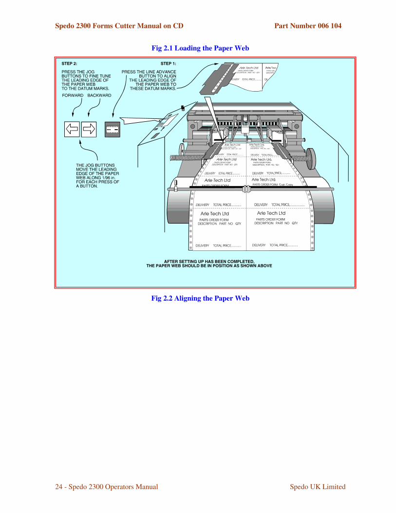
Fig 2.1 Loading the Paper Web
Fig 2.2 Aligning the Paper Web

Spedo 2300 Forms Cutter Manual on CD Part Number 006 104
25 - Spedo 2300 Operators Manual Spedo UK Limited
$%+��*�,#��,�*�!�*�$,��� �+�*�$,���
�!����/�$��$,*�$-��
%�����*��� ��������"�
The major operational components of the paper transport deck are identified on Fig 3.1.
Fig 3.1 Summary of Controls - Paper Transport Deck
��������%�����
The guillotine is operated from the enhanced control panel. The controls are described under three main categories. Fig 3.2 gives a summary of pushbuttons and Fig 3.3 explains the use of the optional batch and total counters and the Speed Adjust slider control.
$%+��*�,#�%�$�+�!�+�
The following procedure is given as a general guide only, laying out a suggested order of setting up and operating the guillotine. It is essential that the operator is familiar with all the controls as summarised in the beginning of this section.
Spedo 2300 Forms Cutter Manual on CD Part Number 006 104
26 - Spedo 2300 Operators Manual Spedo UK Limited
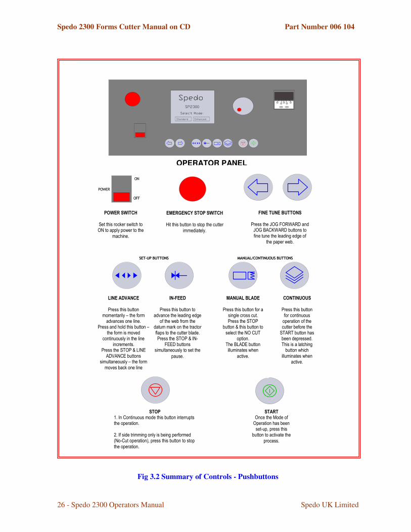
Fig 3.2 Summary of Controls - Pushbuttons
��������������������������������������������
�� �� � � � � ��� �� � � � � ��� �� � � � � ��� �� � � � � �
� � � � � � � � � � � � � � � � � � � � � � � � � � � � � � � � � � � � � � � � � � � � � � � �
�����
��
���
������������
���������� �� �� ������������ �������������
����������� � ��������������������
���������������� ������������ � ���������������� �������������
�������� ��������
�����������
�
���������������������� � ���� � � �� �� ����������
� � ��� �.
�� �� �� � ����������
�
� ��������� � ��� ������ ������ �����
�� � �� �� ���� .
� �� ��� � ��� � �� ��
�
� ���������� � �� � � � � �� � � �� � �! � " # � � � �� � ��� ����$�� ���� � ��������� � �� % ��� % ��$�
����� � � ������ &�
� �� ��� � � � � ��
�
� ����������� � ��� �� � �� �� ���� �'�����$�� �
� � ( � � ���� ����� �&�� ������ � � ���� ������� � ��� �'�
����$�� ����� ( �� �� ��� � � ��� ��� �������� ��
�� ��� �� ��&�� ����������) � �* �+ ,� - �
� . � � " - �� � ��� ����� � ��� � �� ��� �'�����$�� �
� ( ���� � ��� ����� ��
�� �� ��� �
�
� ����������� � ��� ���� � ( � � ��������� � �� % ��� % ��
$�������� �$�� ������ � �� � �� � ���� �������� ���$�� � ��������� ������ �� � �&�� ����������) � �* �,� /
� - - �� � ��� ����� � ��� � �� ��� �����������
� � � ��&�
� � � � � � �� � � � ��
�� ����������� � ��� �$��� �
��� % �������� �&�� ����������) � �
� � ��� �* ������� � ��� �������������� �" 0 ) �
� ��� &�) ���! + � - �� � ��� ����� � �� � �������� �
� ��( �&�
�� �� � �� ��
�� ����������� � ��� �
$��� ��� � � ��� ��� ��� �$������ ������ �$�������
�) � � ) �� � ��� ��� ��� ��� �� �� ������ &�) �������� ��� ���� % �
� � ��� ���������� � �� � �������� �
� ��( �&�
����
1 &�,� �" � ��� � � ��� � �������� � ��� ��� ����� � �������� ��� ��� &��2 &�,$���� ������ � �� % �� �� ����� ��� % �� ��$�� �� �3� /" � ��� ��� ��� 45�� ����������� � ��� ������ �
����� ��� ��� &�
�� ��
� ������6 � ��$� � ��� ��� ��� ��� ��� �
���/� � 5�� ����������� � ��� ���� ��( � �������
� ����&�
OPERATOR PANEL

Spedo 2300 Forms Cutter Manual on CD Part Number 006 104
27 - Spedo 2300 Operators Manual Spedo UK Limited
Fig 3.3 Summary of Controls - Batch Counter

Spedo 2300 Forms Cutter Manual on CD Part Number 006 104
28 - Spedo 2300 Operators Manual Spedo UK Limited
Fig 3.4 Setting the Counter

Spedo 2300 Forms Cutter Manual on CD Part Number 006 104
29 - Spedo 2300 Operators Manual Spedo UK Limited
Fig 3.5 Standard & Enhanced Mode Selection
2300

Spedo 2300 Forms Cutter Manual on CD Part Number 006 104
30 - Spedo 2300 Operators Manual Spedo UK Limited
Fig 3.6 Enhanced Mode - Edit Sequence

Spedo 2300 Forms Cutter Manual on CD Part Number 006 104
31 - Spedo 2300 Operators Manual Spedo UK Limited
Fig 3.7 Enhanced Mode - Job Definition Sequence

Spedo 2300 Forms Cutter Manual on CD Part Number 006 104
32 - Spedo 2300 Operators Manual Spedo UK Limited
3��,�,#��
The putting into operation of the machine, especially the actuation of the cross-cut guillotine blade pre-supposes that the guillotine has been correctly installed by a Spedo trained technician. The manufacturer is not liable for damage caused by non-observance of the procedures given in this manual. Please observe the following precautions before switching on the cutter for the first time:
� Never wear items of loose clothing or other decorative jewellery, such as necklaces or bracelets as they could become entrapped in the moving parts of the machinery.
� Never touch the working area of the longitudinal cross-cut blade. This is applicable especially when standing at the stacker end, when the motor is running.
� If any malfunction occurs, contact the Customer Services Department of Spedo or their agent for assistance. DO NOT ATTEMPT to correct any mechanical malfunction that occurs.
%�����-�������
� Select Standard or Enhanced Mode, as shown on Fig 3.5.
� Standard Mode. Select the required feed, form depth and strip depth using the on-screen digital coding keypad displayed on the touch panel.
� Enhanced Mode. Set up the job sequence and formats as described in Figs 3.5, 3.6 and 3.7.
� Switch on the MAINS switch. Check that the MAINS switch and the STOP switch have illuminated.
� Open the protective cover. Release the centre cutter away from the paper path.
� Open the in-feed tension brush and feed the paper web underneath it over the in-feed plate. Return the in-feed tension brush to its operating position.
� Pull enough length of paper web through so that it can lie unsupported on top of the paper supports.
� Set the space between the tractor units at approximately the required distance and position the paper clamps and paper supports at equal intervals between the tractor units.
� Open the tractor units flaps and pull enough length of paper through so that it now covers the tractor sprockets. Adjust the tractor units until the holes in the paper carrier strip engage onto the tractor sprockets.
� Close the tractor unit flaps and check that the space under the flaps is enough to cater for the weight (thickness) of paper web. If necessary, adjust the height of the RED adjusters until the flaps are at the required setting.
� With the flaps closed, adjust the space between tractor units so that the paper lies flat and is slightly tensioned across its width.

Spedo 2300 Forms Cutter Manual on CD Part Number 006 104
33 - Spedo 2300 Operators Manual Spedo UK Limited
� Close the protective cover. Press the START pushbutton to extinguish the STOP pushbutton. Use the Line Advance pushbutton to align the leading edge of the paper web with the datum marks on the tractor unit flaps. Use the JOG pushbuttons to `fine tune' the alignment
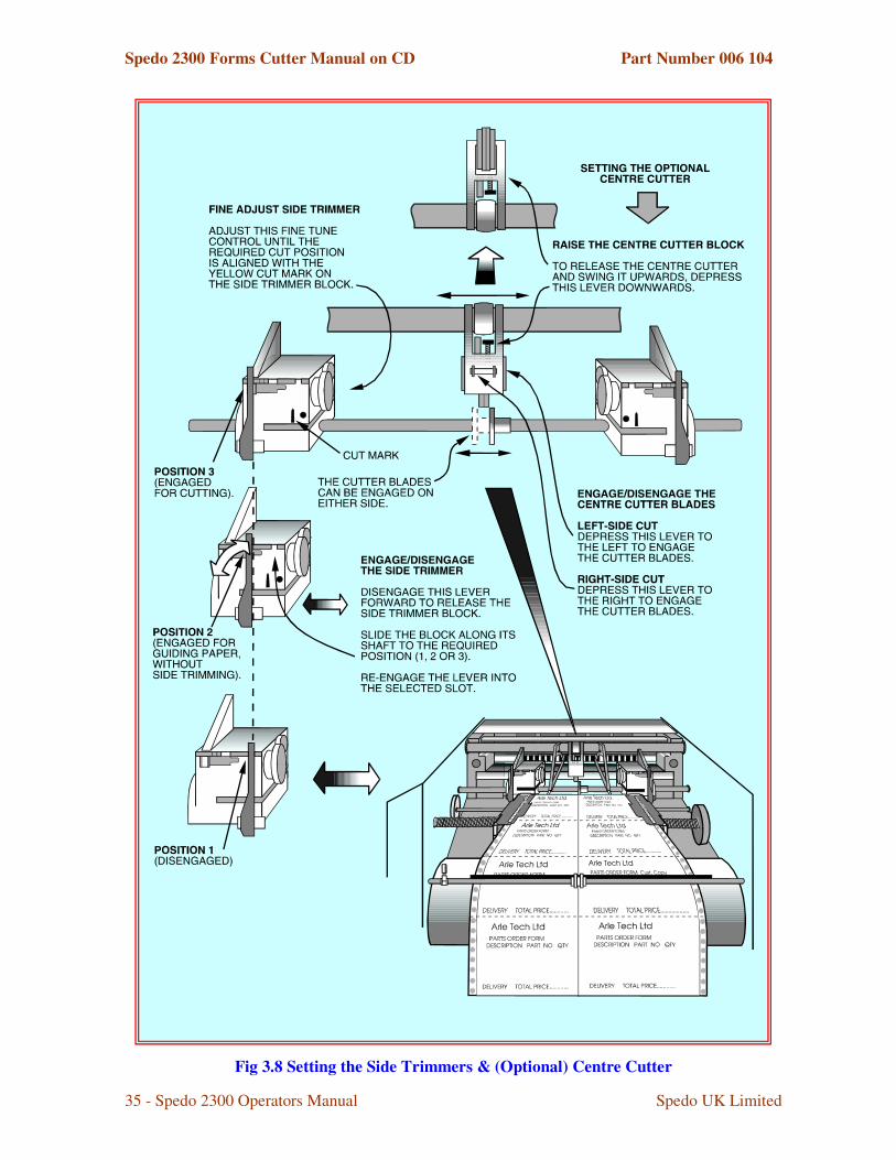
� If side trimming is required, open the protective cover and slide the side trimmer(s) so that the trimmer block(s) engage with the tractor unit(s), (position 3 as shown on Fig 3.9). Align the yellow cut mark with the side carrier cut line.
� If a centre cut is required, engage the centre cutter and adjust its position to align with the centre cut mark on the paper web, as shown in Fig 3.8. Close the protective cover. Press the START pushbutton to extinguish the STOP pushbutton.
� Set the batch counter as required (see Figs 3.3 and 3.4). A pause facility has been incorporated to allow automatic batching of form sets without the need for operator intervention.
� The cutter is now ready to be operated. However, before starting, ensure that a paper loop has formed between the in-feeding ancillary unit (if present) and the guillotine and that the loop will be automatically controlled by the system.
$���������)����������������%�����
The paper transport deck as set up above applies to single cut mode. If a dual strip cut is required to be made according to the digital cut mode keypad, the leading edge of the paper web on the first form to be fed through, can be advanced past the datum marks on the tractor flaps by further use of the JOG pushbuttons.
If the guillotine is to be used with an on-line numbering unit only, so that no cutting is required, refer to the steps given under No-Cut Operation later in this Section. If cutting is required proceed as below.
� Select the mode of cut as described in Section 1.
Having set the guillotine as required above, proceed as follows:
%����������������������$���������
� Press the START pushbutton. Check that the RED STOP pushbutton has extinguished.
� Press the In-Feed pushbutton and check that the leading edge of the paper web advances to the guillotine blade.
� Press the Manual Cross-Cut pushbutton and check that the guillotine blade cuts across the full width of the paper web.
� Press the START pushbutton a few times to produce some cut forms and check the forms for correct cut position and depth. Fine tune the cut position using the JOG pushbuttons.
� It may also be necessary to re-adjust the side trimmers and the centre cutter positions at this time.

Spedo 2300 Forms Cutter Manual on CD Part Number 006 104
34 - Spedo 2300 Operators Manual Spedo UK Limited
� Set the stacking guides and paper stops according to the position and size of the cut forms.
� Start Continuous Operation as detailed below, if required.
Spedo 2300 Forms Cutter Manual on CD Part Number 006 104
35 - Spedo 2300 Operators Manual Spedo UK Limited
Fig 3.8 Setting the Side Trimmers & (Optional) Centre Cutter
Spedo 2300 Forms Cutter Manual on CD Part Number 006 104
36 - Spedo 2300 Operators Manual Spedo UK Limited
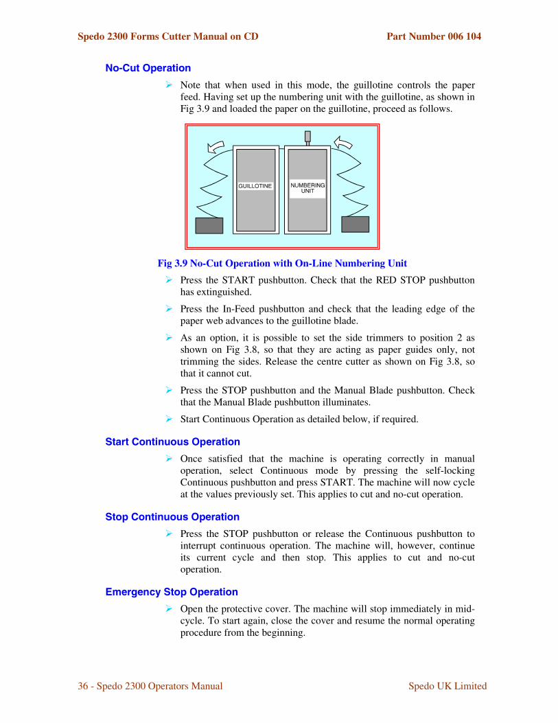
,�9����$���������
� Note that when used in this mode, the guillotine controls the paper feed. Having set up the numbering unit with the guillotine, as shown in Fig 3.9 and loaded the paper on the guillotine, proceed as follows.
Fig 3.9 No-Cut Operation with On-Line Numbering Unit � Press the START pushbutton. Check that the RED STOP pushbutton
has extinguished.
� Press the In-Feed pushbutton and check that the leading edge of the paper web advances to the guillotine blade.
� As an option, it is possible to set the side trimmers to position 2 as shown on Fig 3.8, so that they are acting as paper guides only, not trimming the sides. Release the centre cutter as shown on Fig 3.8, so that it cannot cut.
� Press the STOP pushbutton and the Manual Blade pushbutton. Check that the Manual Blade pushbutton illuminates.
� Start Continuous Operation as detailed below, if required.
��������������� �$���������
� Once satisfied that the machine is operating correctly in manual operation, select Continuous mode by pressing the self-locking Continuous pushbutton and press START. The machine will now cycle at the values previously set. This applies to cut and no-cut operation.
�������������� �$���������
� Press the STOP pushbutton or release the Continuous pushbutton to interrupt continuous operation. The machine will, however, continue its current cycle and then stop. This applies to cut and no-cut operation.
+��������������$���������
� Open the protective cover. The machine will stop immediately in mid-cycle. To start again, close the cover and resume the normal operating procedure from the beginning.

Spedo 2300 Forms Cutter Manual on CD Part Number 006 104
37 - Spedo 2300 Operators Manual Spedo UK Limited
� Note that this method of stopping the machine is bad practice and should not be used for normal operation. This applies to cut and no-cut operation.
%��������9����
� The machine will continue to cycle until the trailing edge of the paper web passes over the paper run-out switch. When this happens, the machine will stop, leaving the last forms unprocessed. This applies to cut and no-cut operation.
� In this instance, de-select the Continuous pushbutton and cycle the remaining forms through manually, by pressing the START pushbutton, using the In-Feed pushbutton to advance the paper and the Manual Blade pushbutton to cut the remaining forms.

Spedo 2300 Forms Cutter Manual on CD Part Number 006 104
38 - Spedo 2300 Operators Manual Spedo UK Limited
$%+��*�$,�-����,*+,�,�+� �+�*�$,�0�
3��,�,#��
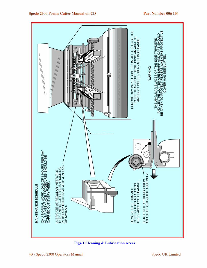
Before starting any preventive maintenance, ensure that the forms cutter has been disconnected from the main electrical supply.
The angular blades on the side trimmers, the centre cutter and the cross-cutter are extremely sharp and care should be taken to protect fingers when the protective cover has been opened.
�-+�,�,#�
� Remove any paper dust or other debris from the inside of the paper transport deck, using an air line or vacuum cleaner. This should be checked on a regular basis and performed as required.
� Open the tractor units and remove any paper dust.
� Clean away any ink residue or other tenaciously adhering debris from bare lubricated parts with a clean cloth.
� Remove each side trimmer guide by slackening the thumbscrew on the side of the trimmer block, as shown in Fig 4.1. This gives access to the trimmer blades. Clean the side trimmer blades using an airline and a soft-hair hand brush.
� Clean the centre cutter blades using a soft-hair hand brush.
� Never use a metal instrument to remove paper debris adhering to the blade surfaces.
� Clean the protective cover using a foam cleaner.
-!1����*�$,�
� Lightly oil the tractor unit drive bushes. Loosen their clamps and slide the units along the splined shaft to spread the oil.
� Lightly oil the centre cutter bush which runs in the centre bridge (see Fig 4.1).
� In order to gain access to the lubrication points on the cross-cutter, the protective cover over the cutter must be removed. This is a task for a service technician and should not be attempted by the operator, unless trained in this procedure by Spedo Ltd.
3��,�,#2�-�������1������� �
� Lithium batteries are used in the equipment, therefore,
� DO NOT dispose of in a fire.
� DO NOT open, crush, dismantle or otherwise mechanically interfere with any part within the forms cutter that contains a Lithium battery.
� Ensure safe disposal of the any part containing a Lithium battery at the end of the battery life.

Spedo 2300 Forms Cutter Manual on CD Part Number 006 104
39 - Spedo 2300 Operators Manual Spedo UK Limited
� In case of fire, use a dry powder extinguisher based on graphite or other suitable extinguisher for alkaline metal fires.
Spedo 2300 Forms Cutter Manual on CD Part Number 006 104
40 - Spedo 2300 Operators Manual Spedo UK Limited
Fig4.1 Cleaning & Lubrication Areas