Embed Size (px)
Citation preview
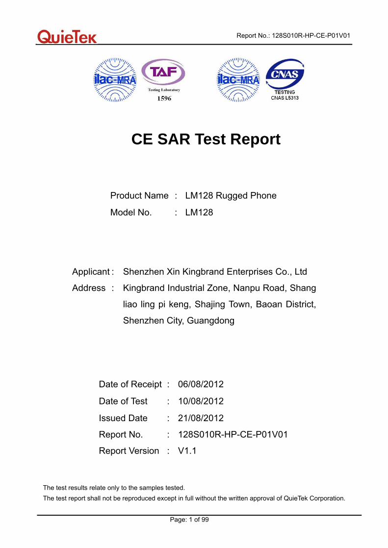
Report No.: 128S010R-HP-CE-P01V01
Page: 1 of 99
CE SAR Test Report
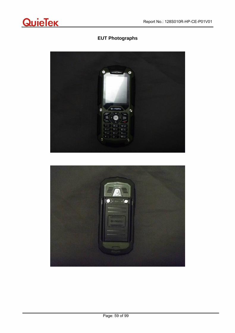
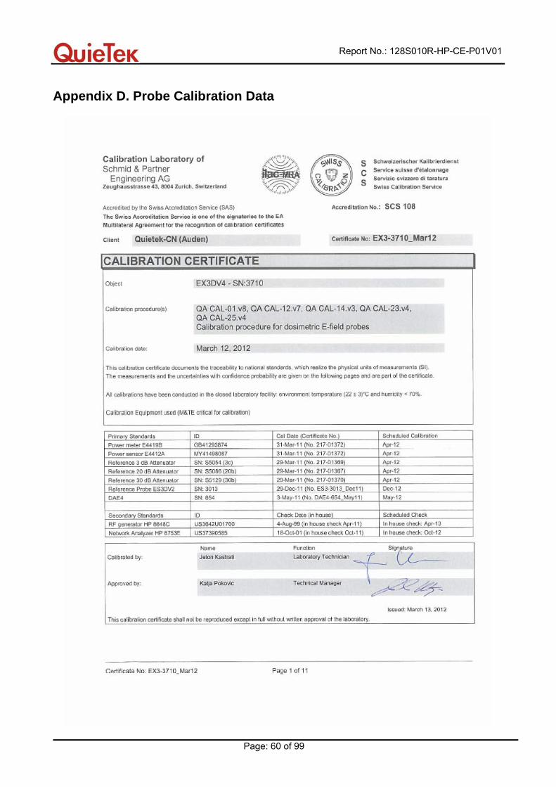
Product Name : LM128 Rugged Phone
Model No. : LM128
Applicant : Shenzhen Xin Kingbrand Enterprises Co., Ltd
Address : Kingbrand Industrial Zone, Nanpu Road, Shang
liao ling pi keng, Shajing Town, Baoan District,
Shenzhen City, Guangdong
Date of Receipt : 06/08/2012
Date of Test : 10/08/2012
Issued Date : 21/08/2012
Report No. : 128S010R-HP-CE-P01V01
Report Version : V1.1
The test results relate only to the samples tested. The test report shall not be reproduced except in full without the written approval of QuieTek Corporation.

Report No.: 128S010R-HP-CE-P01V01
Page: 2 of 99
Test Report Cert i f icat ion Issued Date: 13/08/2012
Report No.: 128S010R-HP-CE-P01V01
Product Name : LM128 Rugged Phone
Applicant : Shenzhen Xin Kingbrand Enterprises Co., Ltd
Address : Kingbrand Industrial Zone, Nanpu Road, Shang liao ling pi keng,
Shajing Town, Baoan District, Shenzhen City, Guangdong
Manufacturer : Shenzhen Xin Kingbrand Enterprises Co., Ltd
Address : K building, Sheng Guang industrial, Nan Dong Dong Huan road,
Huang Pu community, Sha Jing town, Bao An district, Shenzhen
Model No. : LM128
EUT Voltage : DC: 3.7V
Brand Name : Xin Kingbrand
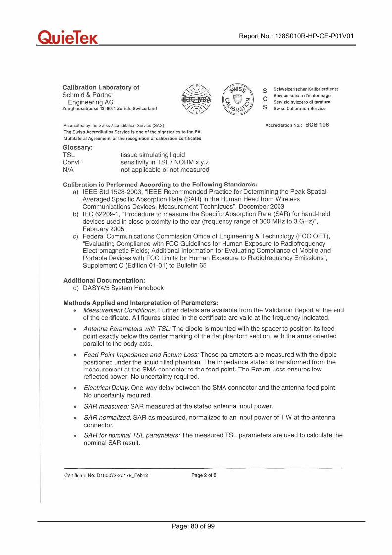
Applicable Standard : EN50360: 2001
EN62209-1: 2006
EN62311: 2008
EN62209-2:2010
Test Result : Max. SAR Measurement (10g)
Head: 0.515 W/kg
Body: 0.680 W/kg
Performed Location : Suzhou EMC Laboratory
No.99 Hongye Rd., Suzhou Industrial Park Loufeng Hi-Tech
Development Zone., Suzhou, China
TEL: +86-512-6251-5088 / FAX: +86-512-6251-5098
Documented By :
(Engineering ADM: Alice Ni)
Reviewed By :
(Engineering Supervisor: Robin Wu)
Approved By :
(Manager: Marlin Chen)
Report No.: 128S010R-HP-CE-P01V01
Page: 3 of 99
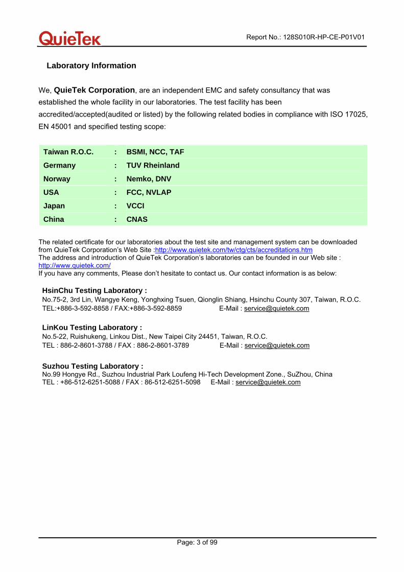
Laboratory Information
We, QuieTek Corporation, are an independent EMC and safety consultancy that was established the whole facility in our laboratories. The test facility has been accredited/accepted(audited or listed) by the following related bodies in compliance with ISO 17025, EN 45001 and specified testing scope:
The related certificate for our laboratories about the test site and management system can be downloaded from QuieTek Corporation’s Web Site :http://www.quietek.com/tw/ctg/cts/accreditations.htm The address and introduction of QuieTek Corporation’s laboratories can be founded in our Web site : http://www.quietek.com/ If you have any comments, Please don’t hesitate to contact us. Our contact information is as below: HsinChu Testing Laboratory : No.75-2, 3rd Lin, Wangye Keng, Yonghxing Tsuen, Qionglin Shiang, Hsinchu County 307, Taiwan, R.O.C. TEL:+886-3-592-8858 / FAX:+886-3-592-8859 E-Mail : [email protected]
LinKou Testing Laboratory : No.5-22, Ruishukeng, Linkou Dist., New Taipei City 24451, Taiwan, R.O.C. TEL : 886-2-8601-3788 / FAX : 886-2-8601-3789 E-Mail : [email protected]
Suzhou Testing Laboratory : No.99 Hongye Rd., Suzhou Industrial Park Loufeng Hi-Tech Development Zone., SuZhou, China TEL : +86-512-6251-5088 / FAX : 86-512-6251-5098 E-Mail : [email protected]
Taiwan R.O.C. : BSMI, NCC, TAF
Germany : TUV Rheinland
Norway : Nemko, DNV
USA : FCC, NVLAP
Japan : VCCI
China : CNAS
Report No.: 128S010R-HP-CE-P01V01
Page: 4 of 99
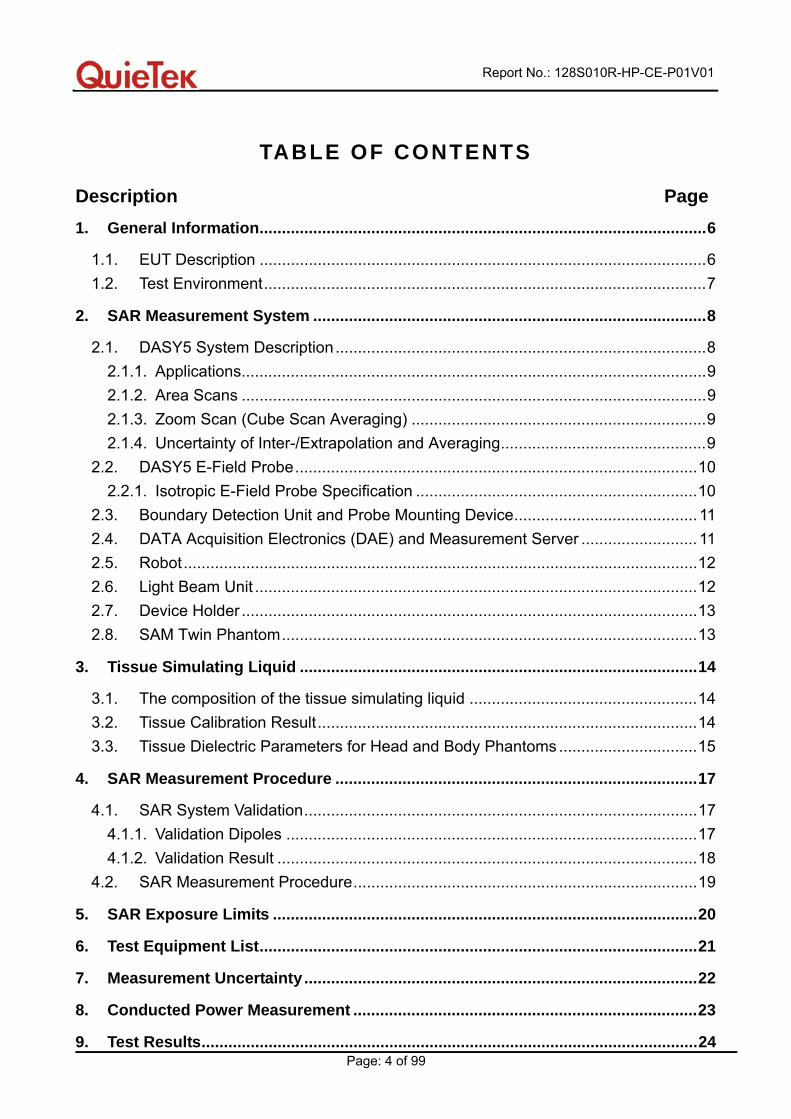
TABLE OF CONTENTS
Description Page
1. General Information....................................................................................................6
1.1. EUT Description ....................................................................................................6 1.2. Test Environment...................................................................................................7
2. SAR Measurement System ........................................................................................8
2.1. DASY5 System Description...................................................................................8 2.1.1. Applications........................................................................................................9 2.1.2. Area Scans ........................................................................................................9 2.1.3. Zoom Scan (Cube Scan Averaging) ..................................................................9 2.1.4. Uncertainty of Inter-/Extrapolation and Averaging..............................................9
2.2. DASY5 E-Field Probe..........................................................................................10 2.2.1. Isotropic E-Field Probe Specification ...............................................................10
2.3. Boundary Detection Unit and Probe Mounting Device......................................... 11 2.4. DATA Acquisition Electronics (DAE) and Measurement Server .......................... 11 2.5. Robot...................................................................................................................12 2.6. Light Beam Unit ...................................................................................................12 2.7. Device Holder ......................................................................................................13 2.8. SAM Twin Phantom.............................................................................................13
3. Tissue Simulating Liquid .........................................................................................14
3.1. The composition of the tissue simulating liquid ...................................................14 3.2. Tissue Calibration Result.....................................................................................14 3.3. Tissue Dielectric Parameters for Head and Body Phantoms ...............................15
4. SAR Measurement Procedure .................................................................................17
4.1. SAR System Validation........................................................................................17 4.1.1. Validation Dipoles ............................................................................................17 4.1.2. Validation Result ..............................................................................................18
4.2. SAR Measurement Procedure.............................................................................19
5. SAR Exposure Limits ...............................................................................................20
6. Test Equipment List..................................................................................................21
7. Measurement Uncertainty........................................................................................22
8. Conducted Power Measurement .............................................................................23
9. Test Results...............................................................................................................24
Report No.: 128S010R-HP-CE-P01V01
Page: 5 of 99
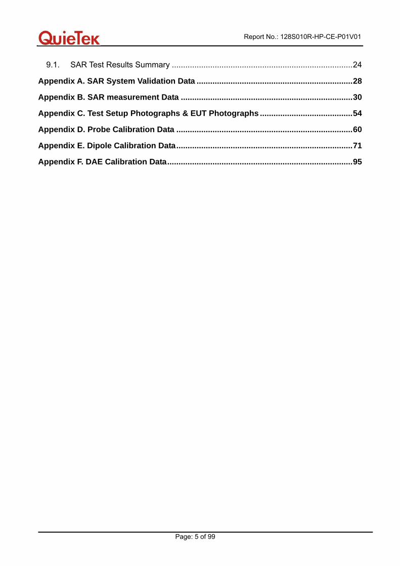
9.1. SAR Test Results Summary ................................................................................24
Appendix A. SAR System Validation Data .....................................................................28
Appendix B. SAR measurement Data ............................................................................30
Appendix C. Test Setup Photographs & EUT Photographs .........................................54
Appendix D. Probe Calibration Data ..............................................................................60
Appendix E. Dipole Calibration Data..............................................................................71
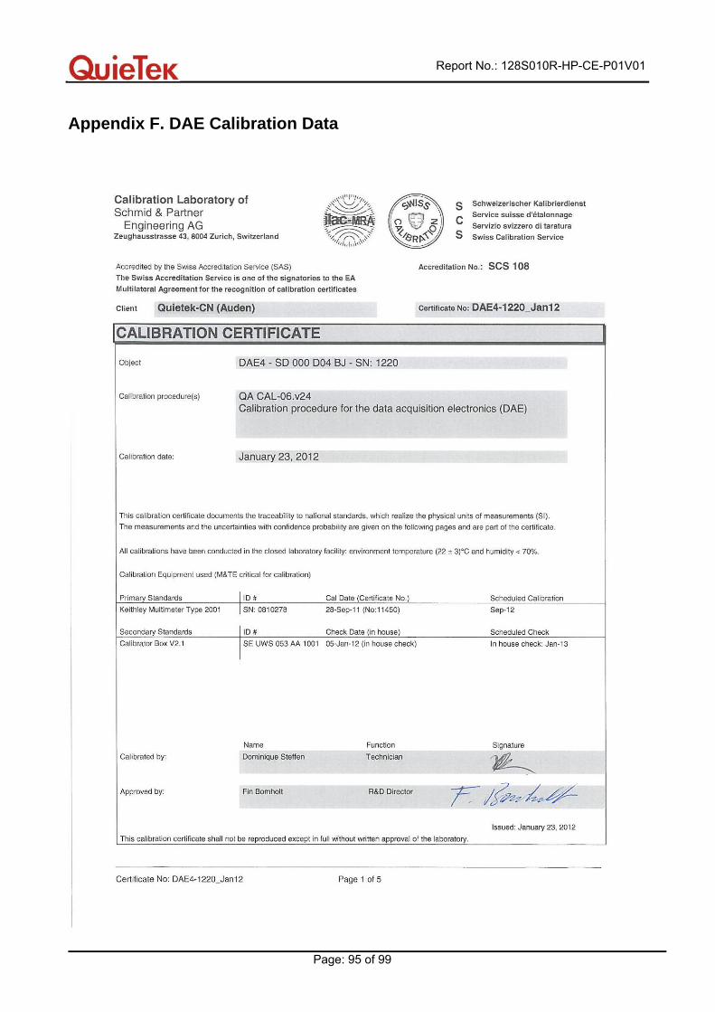
Appendix F. DAE Calibration Data..................................................................................95
Report No.: 128S010R-HP-CE-P01V01
Page: 6 of 99
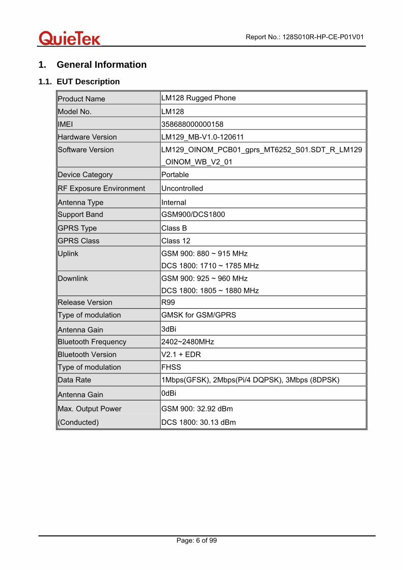
1. General Information
1.1. EUT Description
Product Name LM128 Rugged Phone
Model No. LM128
IMEI 358688000000158
Hardware Version LM129_MB-V1.0-120611
Software Version LM129_OINOM_PCB01_gprs_MT6252_S01.SDT_R_LM129_OINOM_WB_V2_01
Device Category Portable
RF Exposure Environment Uncontrolled
Antenna Type Internal Support Band GSM900/DCS1800
GPRS Type Class B GPRS Class Class 12 Uplink GSM 900: 880 ~ 915 MHz
DCS 1800: 1710 ~ 1785 MHz
Downlink GSM 900: 925 ~ 960 MHz DCS 1800: 1805 ~ 1880 MHz
Release Version R99
Type of modulation GMSK for GSM/GPRS
Antenna Gain 3dBi Bluetooth Frequency 2402~2480MHz
Bluetooth Version V2.1 + EDR
Type of modulation FHSS
Data Rate 1Mbps(GFSK), 2Mbps(Pi/4 DQPSK), 3Mbps (8DPSK)
Antenna Gain 0dBi
Max. Output Power
(Conducted)
GSM 900: 32.92 dBm
DCS 1800: 30.13 dBm
Report No.: 128S010R-HP-CE-P01V01
Page: 7 of 99
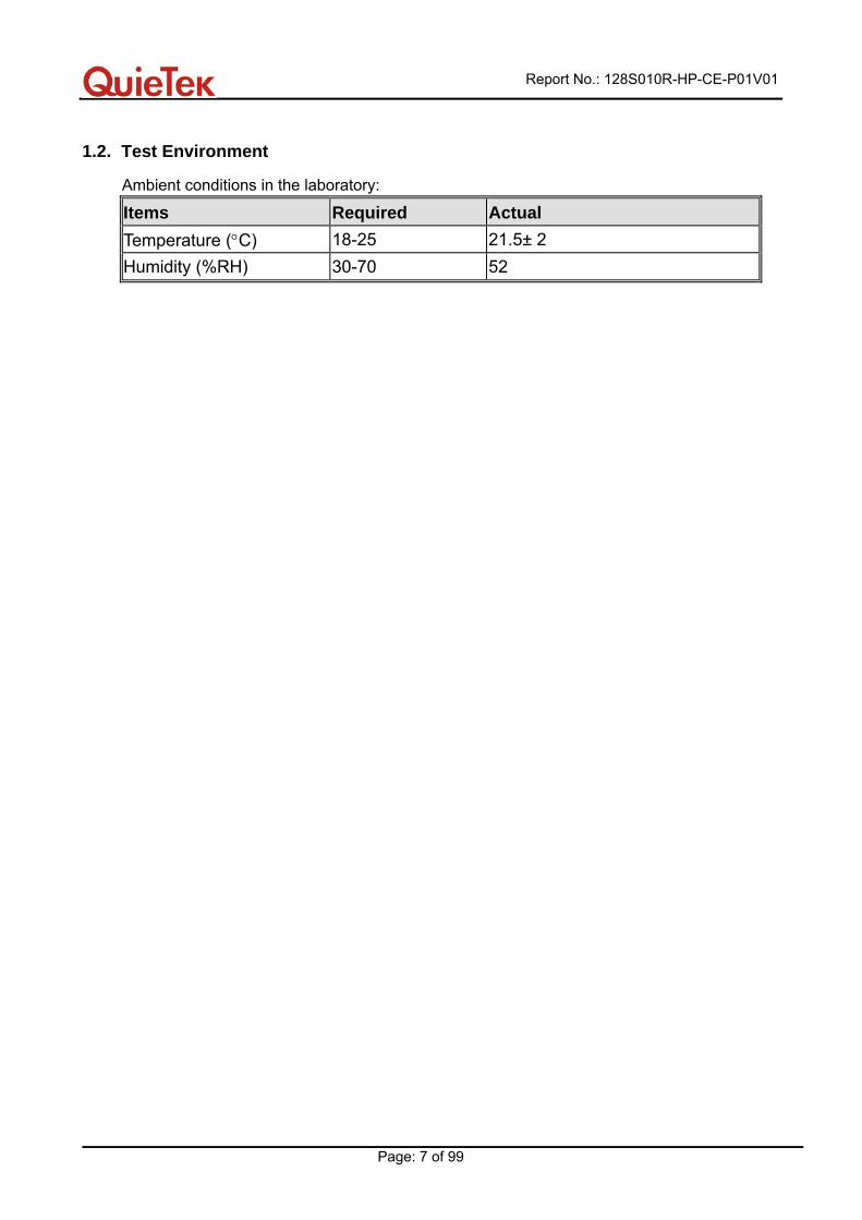
1.2. Test Environment
Ambient conditions in the laboratory:
Items Required Actual Temperature (°C) 18-25 21.5± 2 Humidity (%RH) 30-70 52
Report No.: 128S010R-HP-CE-P01V01
Page: 8 of 99
2. SAR Measurement System
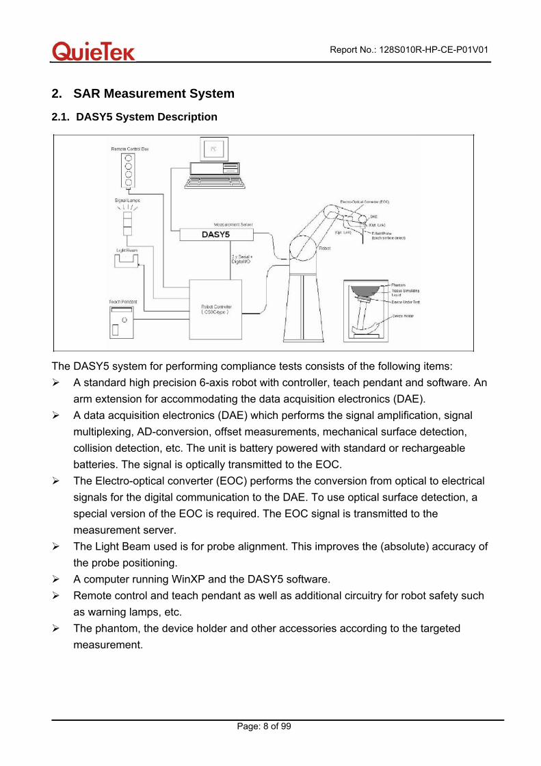
2.1. DASY5 System Description
The DASY5 system for performing compliance tests consists of the following items:
A standard high precision 6-axis robot with controller, teach pendant and software. An arm extension for accommodating the data acquisition electronics (DAE).
A data acquisition electronics (DAE) which performs the signal amplification, signal multiplexing, AD-conversion, offset measurements, mechanical surface detection, collision detection, etc. The unit is battery powered with standard or rechargeable batteries. The signal is optically transmitted to the EOC.
The Electro-optical converter (EOC) performs the conversion from optical to electrical signals for the digital communication to the DAE. To use optical surface detection, a special version of the EOC is required. The EOC signal is transmitted to the measurement server.
The Light Beam used is for probe alignment. This improves the (absolute) accuracy of the probe positioning.
A computer running WinXP and the DASY5 software. Remote control and teach pendant as well as additional circuitry for robot safety such
as warning lamps, etc. The phantom, the device holder and other accessories according to the targeted
measurement.
Report No.: 128S010R-HP-CE-P01V01
Page: 9 of 99
2.1.1. Applications Predefined procedures and evaluations for automated compliance testing with all worldwide standards, e.g., IEEE 1528, OET 65, IEC 62209-1, IEC 62209-2, EN 50360, EN 50383, EN62311 and others. 2.1.2. Area Scans Area scans are defined prior to the measurement process being executed with a user defined variable spacing between each measurement point (integral) allowing low uncertainty measurements to be conducted. Scans defined for FCC applications utilize a 10mm² step integral, with 1mm interpolation used to locate the peak SAR area used for zoom scan assessments. When an Area Scan has measured all reachable points, it computes the field maxima found in the scanned area, within a range of the global maximum. The range (in dB) is specified in the standards for compliance testing. For example, a 2 dB range is required in IEEE 1528-2003 and IEC 62209 standards, whereby 3 dB is a requirement when compliance is assessed in accordance with the ARIB standard (Japan). 2.1.3. Zoom Scan (Cube Scan Averaging) Zoom Scans are used to assess the peak spatial SAR values within a cubic averaging volume containing 1 g and 10 g of simulated tissue. A density of 1000 kg/m³ is used to represent the head and body tissue density and not the phantom liquid density, in order to be consistent with the definition of the liquid dielectric properties, i.e. the side length of the 1 g cube is 10mm, with the side length of the 10 g cube 21,5mm. The zoom scan integer steps can be user defined so as to reduce uncertainty, but normal practice for typical test applications utilize a physical step of 7x7x7 (5mmx5mmx5mm) providing a volume of 30mm in the X & Y axis, and 30mm in the Z axis. 2.1.4. Uncertainty of Inter-/Extrapolation and Averaging In order to evaluate the uncertainty of the interpolation, extrapolation and averaged SAR calculation algorithms of the Postprocessor, DASY5 allows the generation of measurement grids which are artificially predefined by analytically based test functions. Therefore, the grids of area scans and zoom scans can be filled with uncertainty test data, according to the SAR benchmark functions of IEEE 1528.The three analytical functions shown in equations as below are used to describe the possible range of the expected SAR distributions for the tested handsets. The field gradients are covered by the spatially flat distribution f1, the spatially steep distribution f3 and f2 accounts for H-field cancellation on the phantom/tissue surface.
Report No.: 128S010R-HP-CE-P01V01
Page: 10 of 99
2.2. DASY5 E-Field Probe
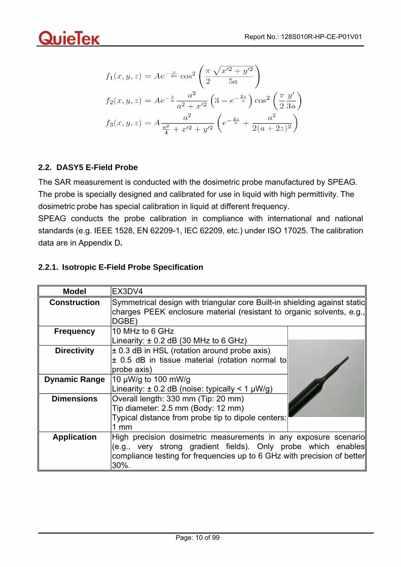
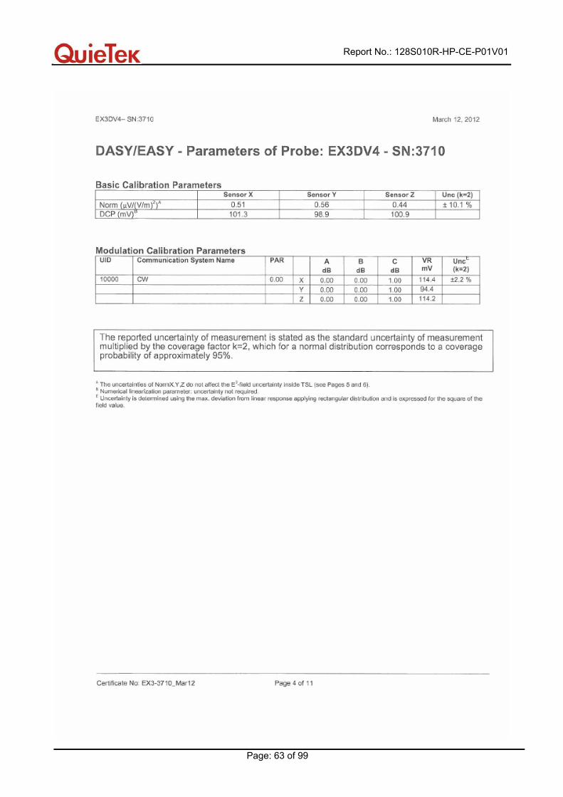
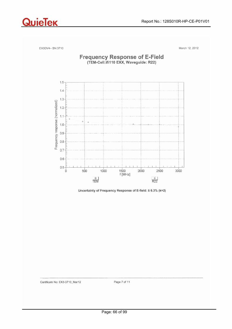
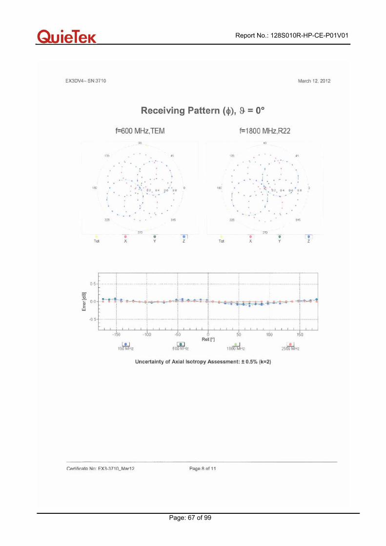
The SAR measurement is conducted with the dosimetric probe manufactured by SPEAG. The probe is specially designed and calibrated for use in liquid with high permittivity. The dosimetric probe has special calibration in liquid at different frequency. SPEAG conducts the probe calibration in compliance with international and national standards (e.g. IEEE 1528, EN 62209-1, IEC 62209, etc.) under ISO 17025. The calibration data are in Appendix D. 2.2.1. Isotropic E-Field Probe Specification
Model EX3DV4 Construction
Symmetrical design with triangular core Built-in shielding against static charges PEEK enclosure material (resistant to organic solvents, e.g., DGBE)
Frequency 10 MHz to 6 GHz Linearity: ± 0.2 dB (30 MHz to 6 GHz)
Directivity ± 0.3 dB in HSL (rotation around probe axis) ± 0.5 dB in tissue material (rotation normal to probe axis)
Dynamic Range 10 µW/g to 100 mW/g Linearity: ± 0.2 dB (noise: typically < 1 µW/g)
Dimensions Overall length: 330 mm (Tip: 20 mm) Tip diameter: 2.5 mm (Body: 12 mm) Typical distance from probe tip to dipole centers: 1 mm
Application High precision dosimetric measurements in any exposure scenario (e.g., very strong gradient fields). Only probe which enables compliance testing for frequencies up to 6 GHz with precision of better 30%.
Report No.: 128S010R-HP-CE-P01V01
Page: 11 of 99
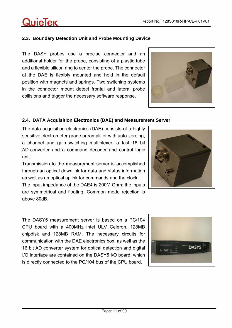
2.3. Boundary Detection Unit and Probe Mounting Device
The DASY probes use a precise connector and an additional holder for the probe, consisting of a plastic tube and a flexible silicon ring to center the probe. The connector at the DAE is flexibly mounted and held in the default position with magnets and springs. Two switching systems in the connector mount detect frontal and lateral probe collisions and trigger the necessary software response.
2.4. DATA Acquisition Electronics (DAE) and Measurement Server
The data acquisition electronics (DAE) consists of a highly sensitive electrometer-grade preamplifier with auto-zeroing, a channel and gain-switching multiplexer, a fast 16 bit AD-converter and a command decoder and control logic unit. Transmission to the measurement server is accomplished through an optical downlink for data and status information as well as an optical uplink for commands and the clock. The input impedance of the DAE4 is 200M Ohm; the inputs are symmetrical and floating. Common mode rejection is above 80dB. The DASY5 measurement server is based on a PC/104 CPU board with a 400MHz intel ULV Celeron, 128MB chipdisk and 128MB RAM. The necessary circuits for communication with the DAE electronics box, as well as the 16 bit AD converter system for optical detection and digital I/O interface are contained on the DASY5 I/O board, which is directly connected to the PC/104 bus of the CPU board.
Report No.: 128S010R-HP-CE-P01V01
Page: 12 of 99
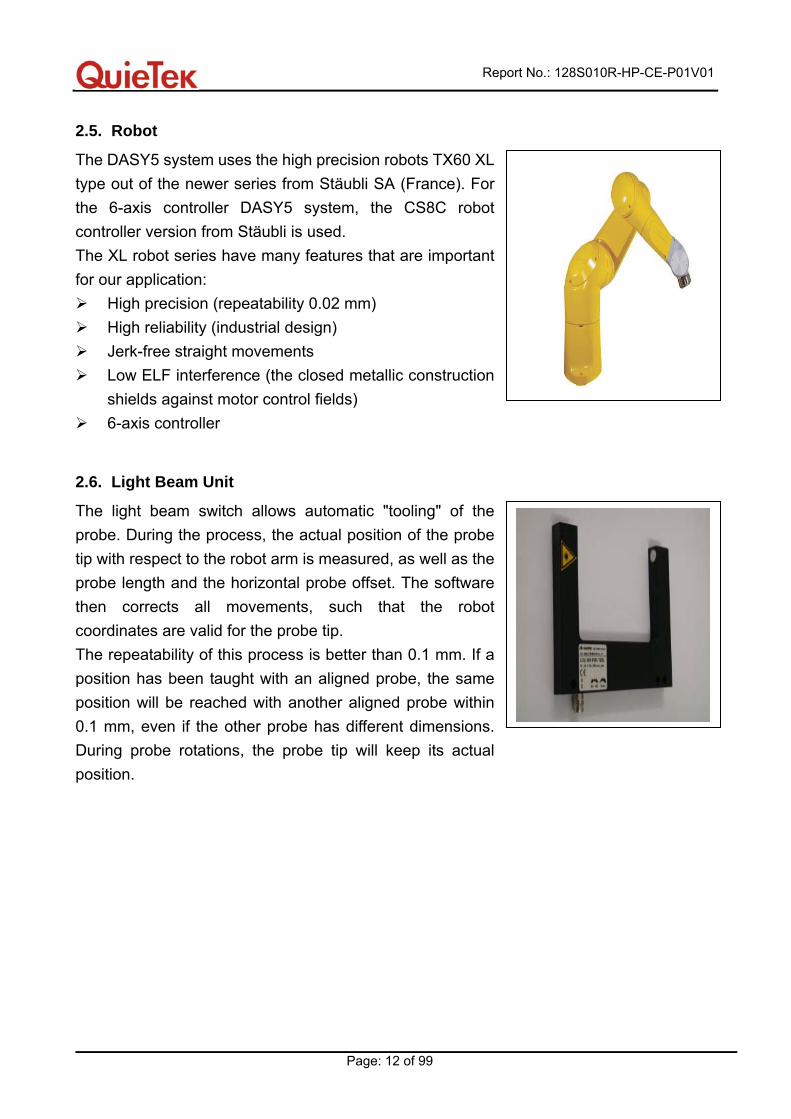
2.5. Robot
The DASY5 system uses the high precision robots TX60 XL type out of the newer series from Stäubli SA (France). For the 6-axis controller DASY5 system, the CS8C robot controller version from Stäubli is used. The XL robot series have many features that are important for our application:
High precision (repeatability 0.02 mm) High reliability (industrial design) Jerk-free straight movements Low ELF interference (the closed metallic construction
shields against motor control fields) 6-axis controller
2.6. Light Beam Unit
The light beam switch allows automatic "tooling" of the probe. During the process, the actual position of the probe tip with respect to the robot arm is measured, as well as the probe length and the horizontal probe offset. The software then corrects all movements, such that the robot coordinates are valid for the probe tip. The repeatability of this process is better than 0.1 mm. If a position has been taught with an aligned probe, the same position will be reached with another aligned probe within 0.1 mm, even if the other probe has different dimensions. During probe rotations, the probe tip will keep its actual position.
Report No.: 128S010R-HP-CE-P01V01
Page: 13 of 99
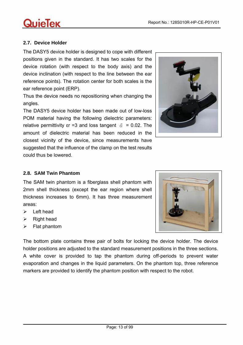
2.7. Device Holder
The DASY5 device holder is designed to cope with different positions given in the standard. It has two scales for the device rotation (with respect to the body axis) and the device inclination (with respect to the line between the ear reference points). The rotation center for both scales is the ear reference point (ERP). Thus the device needs no repositioning when changing the angles. The DASY5 device holder has been made out of low-loss POM material having the following dielectric parameters: relative permittivity εr =3 and loss tangent δ = 0.02. The amount of dielectric material has been reduced in the closest vicinity of the device, since measurements have suggested that the influence of the clamp on the test results could thus be lowered.
2.8. SAM Twin Phantom
The SAM twin phantom is a fiberglass shell phantom with 2mm shell thickness (except the ear region where shell thickness increases to 6mm). It has three measurement areas:
Left head Right head Flat phantom
The bottom plate contains three pair of bolts for locking the device holder. The device holder positions are adjusted to the standard measurement positions in the three sections. A white cover is provided to tap the phantom during off-periods to prevent water evaporation and changes in the liquid parameters. On the phantom top, three reference markers are provided to identify the phantom position with respect to the robot.
Report No.: 128S010R-HP-CE-P01V01
Page: 14 of 99
3. Tissue Simulating Liquid
3.1. The composition of the tissue simulating liquid
INGREDIENT (% Weight)
900MHz Head
900MHz Body
1800MHz Head
1800MHz Body
Water 40.92 56 52.64 40.5 Salt 1.48 0.768 0.36 0.5 Sugar 56.5 41.76 0.00 58 HEC 0.40 1.21 0.00 0.5 Preventol 0.10 0.27 0.00 0.5 DGBE 0.00 0.00 47.0 0.00
3.2. Tissue Calibration Result
The dielectric parameters of the liquids were verified prior to the SAR evaluation using DASY5 Dielectric Probe Kit and Agilent Vector Network Analyzer E5071C
Head/Body Tissue Simulant Measurement Dielectric Parameters Frequency
[MHz] Description ε r σ [s/m]
Tissue Temp.[°C]
Reference result ± 5% window
41.50 39.43 to 43.58
0.97 0.92 to 1.02 N/A
900 MHz 10-08-2012 40.72 0.95 21.0
Reference result ± 5% window
40.00 38.00 to 42.00
1.40 1.33 to 1.47 N/A
1800 MHz 10-08-2012 40.32 1.39 21.0
Report No.: 128S010R-HP-CE-P01V01
Page: 15 of 99
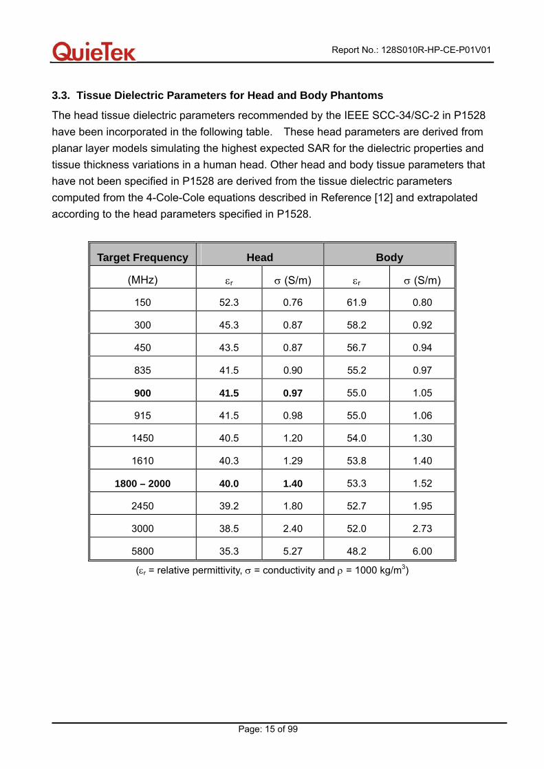
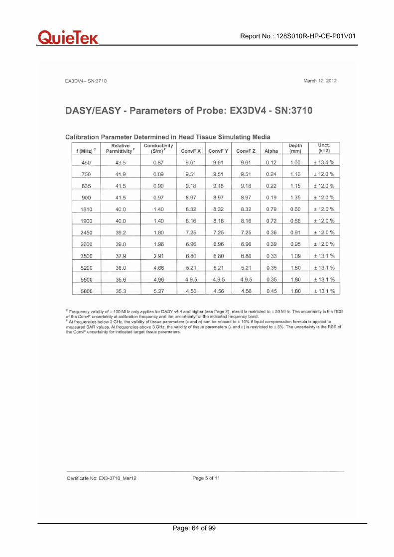
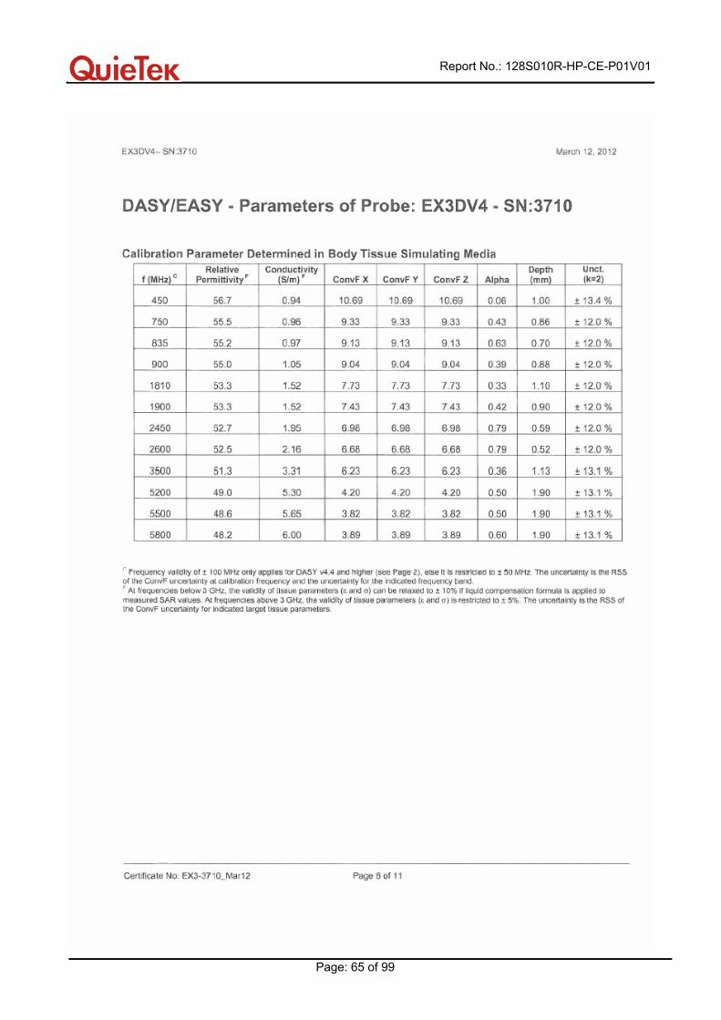
3.3. Tissue Dielectric Parameters for Head and Body Phantoms The head tissue dielectric parameters recommended by the IEEE SCC-34/SC-2 in P1528 have been incorporated in the following table. These head parameters are derived from planar layer models simulating the highest expected SAR for the dielectric properties and tissue thickness variations in a human head. Other head and body tissue parameters that have not been specified in P1528 are derived from the tissue dielectric parameters computed from the 4-Cole-Cole equations described in Reference [12] and extrapolated according to the head parameters specified in P1528.
Target Frequency Head Body
(MHz) εr σ (S/m) εr σ (S/m)
150 52.3 0.76 61.9 0.80
300 45.3 0.87 58.2 0.92
450 43.5 0.87 56.7 0.94
835 41.5 0.90 55.2 0.97
900 41.5 0.97 55.0 1.05
915 41.5 0.98 55.0 1.06
1450 40.5 1.20 54.0 1.30
1610 40.3 1.29 53.8 1.40
1800 – 2000 40.0 1.40 53.3 1.52
2450 39.2 1.80 52.7 1.95
3000 38.5 2.40 52.0 2.73
5800 35.3 5.27 48.2 6.00
(εr = relative permittivity, σ = conductivity and ρ = 1000 kg/m3)
Report No.: 128S010R-HP-CE-P01V01
Page: 16 of 99
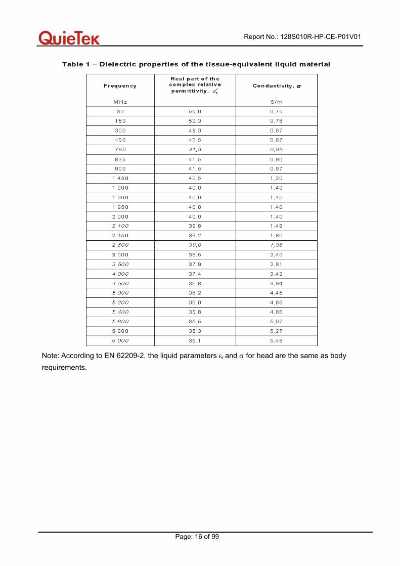
Note: According to EN 62209-2, the liquid parameters εr and σ for head are the same as body requirements.
Report No.: 128S010R-HP-CE-P01V01
Page: 17 of 99
4. SAR Measurement Procedure
4.1. SAR System Validation
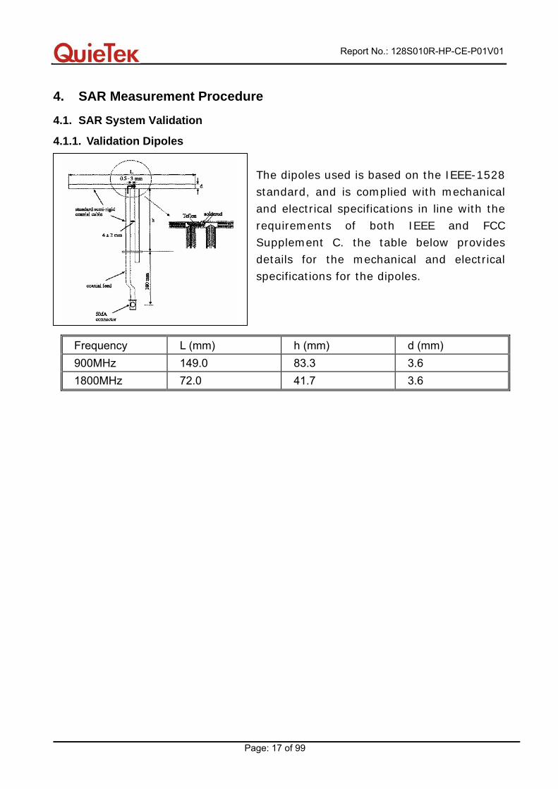
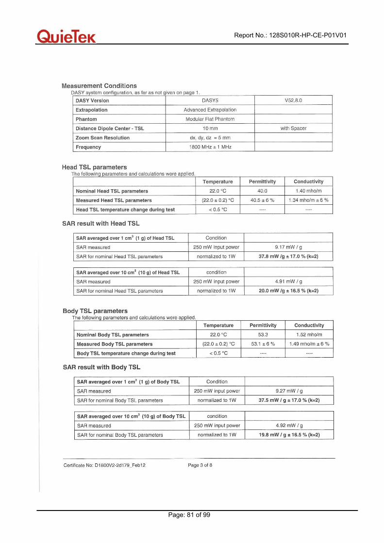
4.1.1. Validation Dipoles The dipoles used is based on the IEEE-1528 standard, and is complied with mechanical and electrical specifications in line with the requirements of both IEEE and FCC Supplement C. the table below provides details for the mechanical and electrical specifications for the dipoles.
Frequency L (mm) h (mm) d (mm) 900MHz 149.0 83.3 3.6 1800MHz 72.0 41.7 3.6
Report No.: 128S010R-HP-CE-P01V01
Page: 18 of 99
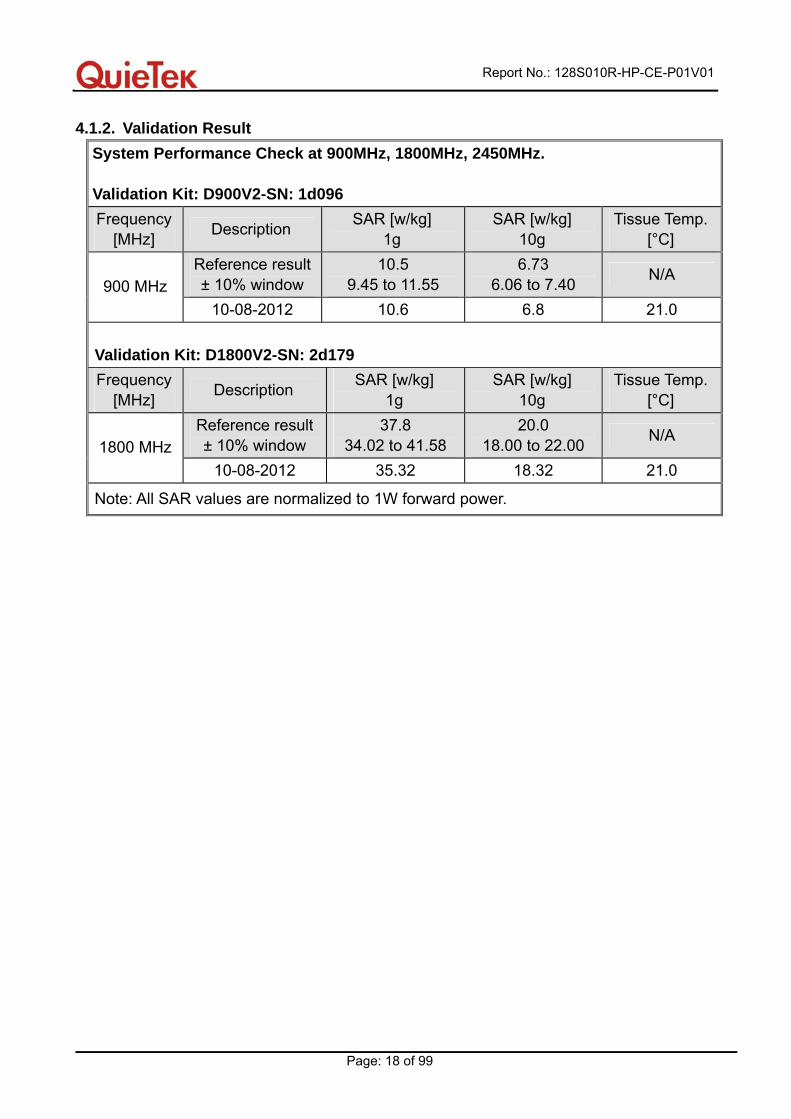
4.1.2. Validation Result System Performance Check at 900MHz, 1800MHz, 2450MHz. Validation Kit: D900V2-SN: 1d096 Frequency
[MHz] Description SAR [w/kg] 1g
SAR [w/kg] 10g
Tissue Temp. [°C]
Reference result ± 10% window
10.5 9.45 to 11.55
6.73 6.06 to 7.40 N/A
900 MHz 10-08-2012 10.6 6.8 21.0
Validation Kit: D1800V2-SN: 2d179 Frequency
[MHz] Description SAR [w/kg] 1g
SAR [w/kg] 10g
Tissue Temp. [°C]
Reference result ± 10% window
37.8 34.02 to 41.58
20.0 18.00 to 22.00 N/A
1800 MHz 10-08-2012 35.32 18.32 21.0
Note: All SAR values are normalized to 1W forward power.

Report No.: 128S010R-HP-CE-P01V01
Page: 19 of 99
4.2. SAR Measurement Procedure
The DASY5 calculates SAR using the following equation,
σ: represents the simulated tissue conductivity ρ: represents the tissue density
The EUT is set to transmit at the required power in line with product specification, at each frequency relating to the LOW, MID, and HIGH channel settings. Pre-scans are made on the device to establish the location for the transmitting antenna, using a large area scan in either air or tissue simulation fluid. The EUT is placed against the Universal Phantom where the maximum area scan dimensions are larger than the physical size of the resonating antenna. When the scan size is not large enough to cover the peak SAR distribution, it is modified by either extending the area scan size in both the X and Y directions, or the device is shifted within the predefined area. The area scan is then run to establish the peak SAR location (interpolated resolution set at 1mm² ) which is then used to orient the center of the zoom scan. The zoom scan is then executed and the 1g and 10g averages are derived from the zoom scan volume (interpolated resolution set at 1mm³ ).
Report No.: 128S010R-HP-CE-P01V01
Page: 20 of 99
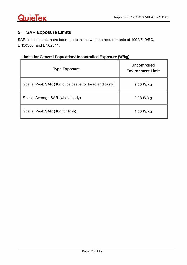
5. SAR Exposure Limits SAR assessments have been made in line with the requirements of 1999/519/EC, EN50360, and EN62311.
Limits for General Population/Uncontrolled Exposure (W/kg)
Type Exposure Uncontrolled
Environment Limit
Spatial Peak SAR (10g cube tissue for head and trunk) 2.00 W/kg
Spatial Average SAR (whole body) 0.08 W/kg
Spatial Peak SAR (10g for limb) 4.00 W/kg
Report No.: 128S010R-HP-CE-P01V01
Page: 21 of 99
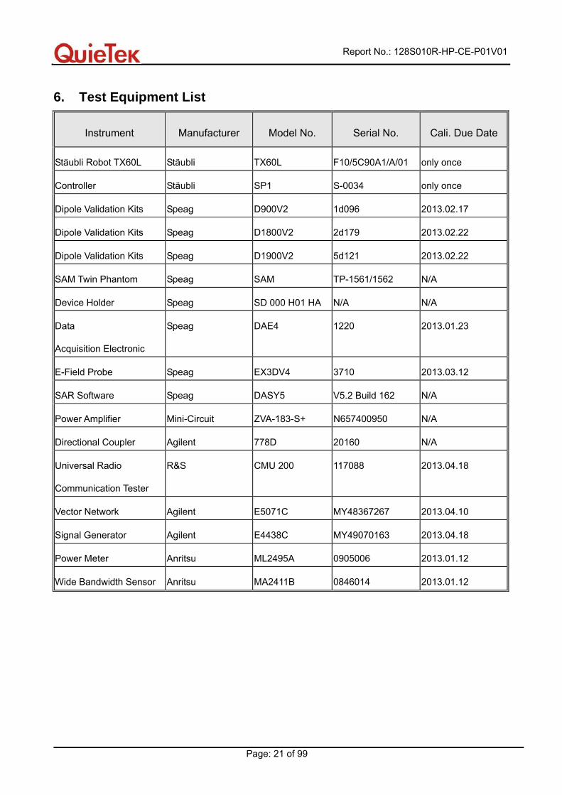
6. Test Equipment List
Instrument Manufacturer Model No. Serial No. Cali. Due Date
Stäubli Robot TX60L Stäubli TX60L F10/5C90A1/A/01 only once
Controller Stäubli SP1 S-0034 only once
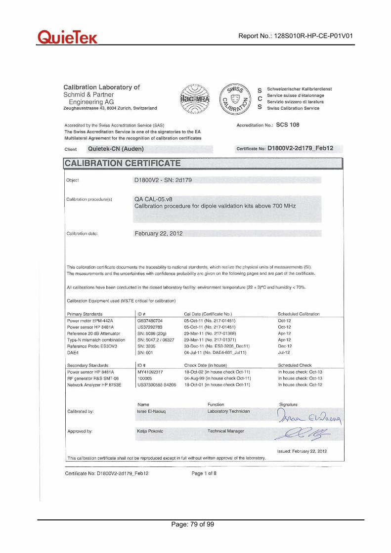
Dipole Validation Kits Speag D900V2 1d096 2013.02.17
Dipole Validation Kits Speag D1800V2 2d179 2013.02.22
Dipole Validation Kits Speag D1900V2 5d121 2013.02.22
SAM Twin Phantom Speag SAM TP-1561/1562 N/A
Device Holder Speag SD 000 H01 HA N/A N/A
Data
Acquisition Electronic
Speag DAE4 1220 2013.01.23
E-Field Probe Speag EX3DV4 3710 2013.03.12
SAR Software Speag DASY5 V5.2 Build 162 N/A
Power Amplifier Mini-Circuit ZVA-183-S+ N657400950 N/A
Directional Coupler Agilent 778D 20160 N/A
Universal Radio
Communication Tester
R&S CMU 200 117088 2013.04.18
Vector Network Agilent E5071C MY48367267 2013.04.10
Signal Generator Agilent E4438C MY49070163 2013.04.18
Power Meter Anritsu ML2495A 0905006 2013.01.12
Wide Bandwidth Sensor Anritsu MA2411B 0846014 2013.01.12
Report No.: 128S010R-HP-CE-P01V01
Page: 22 of 99
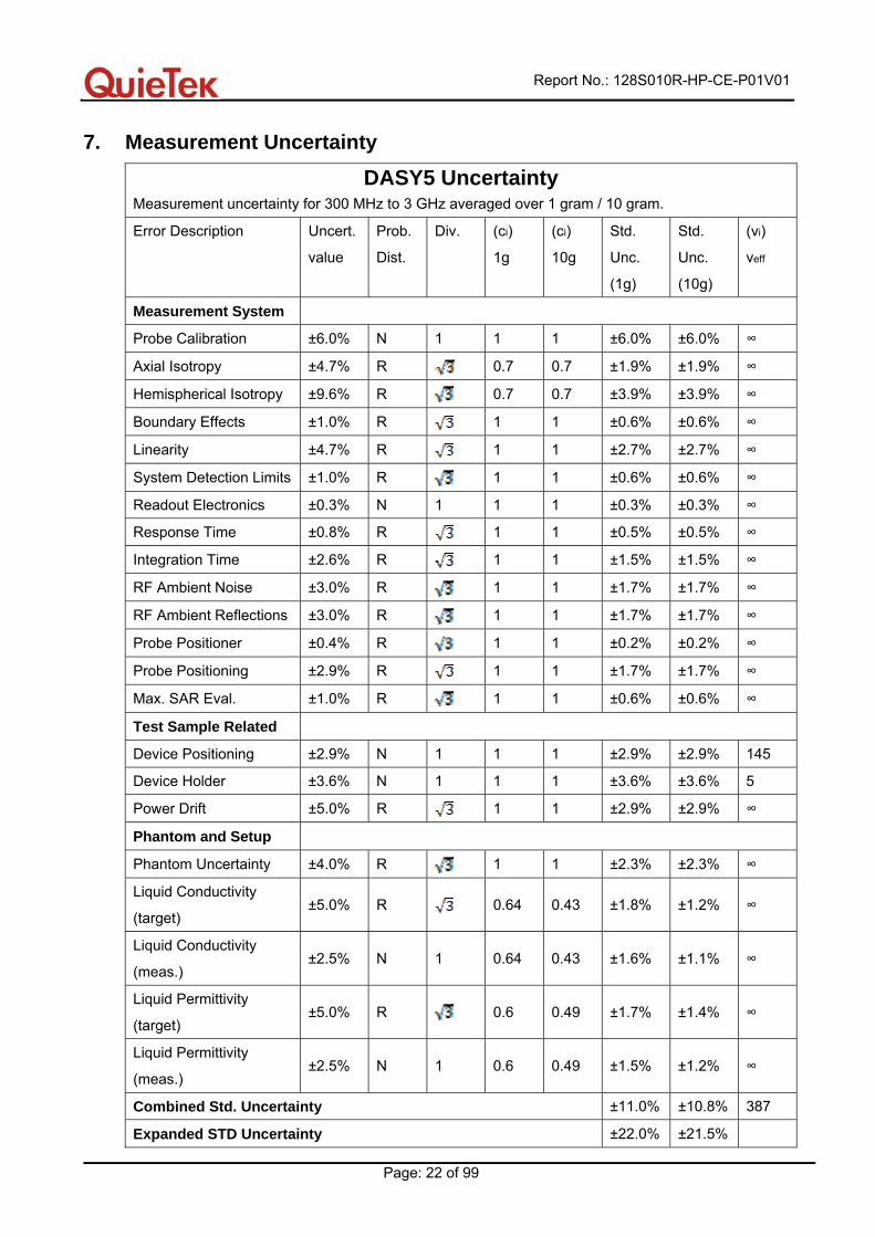
7. Measurement Uncertainty
DASY5 Uncertainty Measurement uncertainty for 300 MHz to 3 GHz averaged over 1 gram / 10 gram. Error Description Uncert.
value Prob.
Dist. Div. (ci)
1g (ci)
10g Std.
Unc.
(1g)
Std.
Unc.
(10g)
(vi)
veff
Measurement System Probe Calibration ±6.0% N 1 1 1 ±6.0% ±6.0% ∞
Axial Isotropy ±4.7% R 0.7 0.7 ±1.9% ±1.9% ∞
Hemispherical Isotropy ±9.6% R 0.7 0.7 ±3.9% ±3.9% ∞
Boundary Effects ±1.0% R 1 1 ±0.6% ±0.6% ∞
Linearity ±4.7% R 1 1 ±2.7% ±2.7% ∞
System Detection Limits ±1.0% R 1 1 ±0.6% ±0.6% ∞
Readout Electronics ±0.3% N 1 1 1 ±0.3% ±0.3% ∞
Response Time ±0.8% R 1 1 ±0.5% ±0.5% ∞
Integration Time ±2.6% R 1 1 ±1.5% ±1.5% ∞
RF Ambient Noise ±3.0% R 1 1 ±1.7% ±1.7% ∞
RF Ambient Reflections ±3.0% R 1 1 ±1.7% ±1.7% ∞
Probe Positioner ±0.4% R 1 1 ±0.2% ±0.2% ∞
Probe Positioning ±2.9% R 1 1 ±1.7% ±1.7% ∞
Max. SAR Eval. ±1.0% R 1 1 ±0.6% ±0.6% ∞
Test Sample Related Device Positioning ±2.9% N 1 1 1 ±2.9% ±2.9% 145
Device Holder ±3.6% N 1 1 1 ±3.6% ±3.6% 5
Power Drift ±5.0% R 1 1 ±2.9% ±2.9% ∞
Phantom and Setup Phantom Uncertainty ±4.0% R 1 1 ±2.3% ±2.3% ∞
Liquid Conductivity
(target) ±5.0% R 0.64 0.43 ±1.8% ±1.2% ∞
Liquid Conductivity
(meas.) ±2.5% N 1 0.64 0.43 ±1.6% ±1.1% ∞
Liquid Permittivity
(target) ±5.0% R 0.6 0.49 ±1.7% ±1.4% ∞
Liquid Permittivity
(meas.) ±2.5% N 1 0.6 0.49 ±1.5% ±1.2% ∞
Combined Std. Uncertainty ±11.0% ±10.8% 387
Expanded STD Uncertainty ±22.0% ±21.5%
Report No.: 128S010R-HP-CE-P01V01
Page: 23 of 99
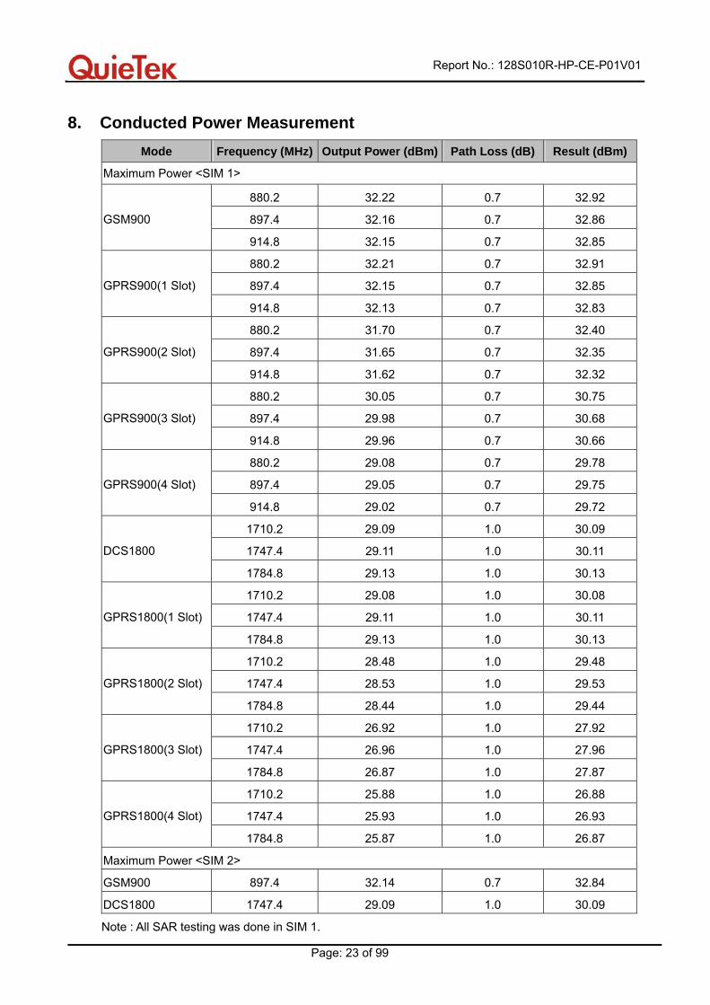
8. Conducted Power Measurement Mode Frequency (MHz) Output Power (dBm) Path Loss (dB) Result (dBm)
Maximum Power <SIM 1>
880.2 32.22 0.7 32.92
897.4 32.16 0.7 32.86 GSM900
914.8 32.15 0.7 32.85
880.2 32.21 0.7 32.91
897.4 32.15 0.7 32.85 GPRS900(1 Slot)
914.8 32.13 0.7 32.83
880.2 31.70 0.7 32.40
897.4 31.65 0.7 32.35 GPRS900(2 Slot)
914.8 31.62 0.7 32.32
880.2 30.05 0.7 30.75
897.4 29.98 0.7 30.68 GPRS900(3 Slot)
914.8 29.96 0.7 30.66
880.2 29.08 0.7 29.78
897.4 29.05 0.7 29.75 GPRS900(4 Slot)
914.8 29.02 0.7 29.72
1710.2 29.09 1.0 30.09
1747.4 29.11 1.0 30.11 DCS1800
1784.8 29.13 1.0 30.13
1710.2 29.08 1.0 30.08
1747.4 29.11 1.0 30.11 GPRS1800(1 Slot)
1784.8 29.13 1.0 30.13
1710.2 28.48 1.0 29.48
1747.4 28.53 1.0 29.53 GPRS1800(2 Slot)
1784.8 28.44 1.0 29.44
1710.2 26.92 1.0 27.92
1747.4 26.96 1.0 27.96 GPRS1800(3 Slot)
1784.8 26.87 1.0 27.87
1710.2 25.88 1.0 26.88
1747.4 25.93 1.0 26.93 GPRS1800(4 Slot)
1784.8 25.87 1.0 26.87
Maximum Power <SIM 2>
GSM900 897.4 32.14 0.7 32.84
DCS1800 1747.4 29.09 1.0 30.09
Note : All SAR testing was done in SIM 1.
Report No.: 128S010R-HP-CE-P01V01
Page: 24 of 99
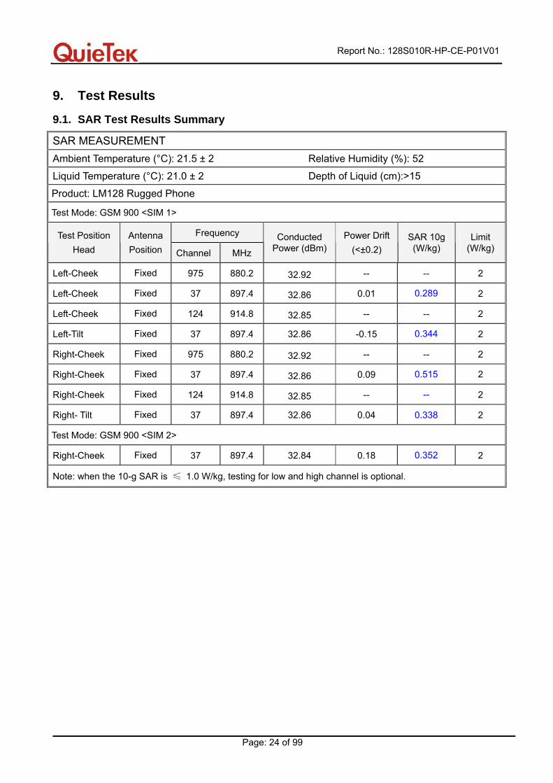
9. Test Results
9.1. SAR Test Results Summary
SAR MEASUREMENT Ambient Temperature (°C): 21.5 ± 2 Relative Humidity (%): 52
Liquid Temperature (°C): 21.0 ± 2 Depth of Liquid (cm):>15
Product: LM128 Rugged Phone
Test Mode: GSM 900 <SIM 1>
Frequency Test Position Head
AntennaPosition Channel MHz
Conducted Power (dBm)
Power Drift(<±0.2)
SAR 10g (W/kg)
Limit (W/kg)
Left-Cheek Fixed 975 880.2 32.92 -- -- 2
Left-Cheek Fixed 37 897.4 32.86 0.01 0.289 2
Left-Cheek Fixed 124 914.8 32.85 -- -- 2
Left-Tilt Fixed 37 897.4 32.86 -0.15 0.344 2
Right-Cheek Fixed 975 880.2 32.92 -- -- 2
Right-Cheek Fixed 37 897.4 32.86 0.09 0.515 2
Right-Cheek Fixed 124 914.8 32.85 -- -- 2
Right- Tilt Fixed 37 897.4 32.86 0.04 0.338 2
Test Mode: GSM 900 <SIM 2>
Right-Cheek Fixed 37 897.4 32.84 0.18 0.352 2
Note: when the 10-g SAR is ≤ 1.0 W/kg, testing for low and high channel is optional.
Report No.: 128S010R-HP-CE-P01V01
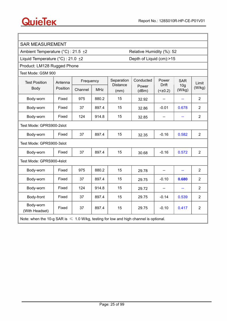
Page: 25 of 99
SAR MEASUREMENT
Ambient Temperature (°C) : 21.5 ±2 Relative Humidity (%): 52
Liquid Temperature (°C) : 21.0 ±2 Depth of Liquid (cm):>15
Product: LM128 Rugged Phone
Test Mode: GSM 900
Frequency Test Position Body
AntennaPosition Channel MHz
Separation Distance
(mm)
Conducted Power (dBm)
Power Drift
(<±0.2)
SAR 10g
(W/kg)
Limit (W/kg)
Body-worn Fixed 975 880.2 15 32.92 -- -- 2
Body-worn Fixed 37 897.4 15 32.86 -0.01 0.678 2
Body-worn Fixed 124 914.8 15 32.85 -- -- 2
Test Mode: GPRS900-2slot
Body-worn Fixed 37 897.4 15 32.35 -0.16 0.582 2
Test Mode: GPRS900-3slot
Body-worn Fixed 37 897.4 15 30.68 -0.16 0.572 2
Test Mode: GPRS900-4slot
Body-worn Fixed 975 880.2 15 29.78 -- -- 2
Body-worn Fixed 37 897.4 15 29.75 -0.10 0.680 2
Body-worn Fixed 124 914.8 15 29.72 -- -- 2
Body-front Fixed 37 897.4 15 29.75 -0.14 0.539 2
Body-worn (With Headset)
Fixed 37 897.4 15 29.75 -0.10 0.417 2
Note: when the 10-g SAR is ≤ 1.0 W/kg, testing for low and high channel is optional.
Report No.: 128S010R-HP-CE-P01V01
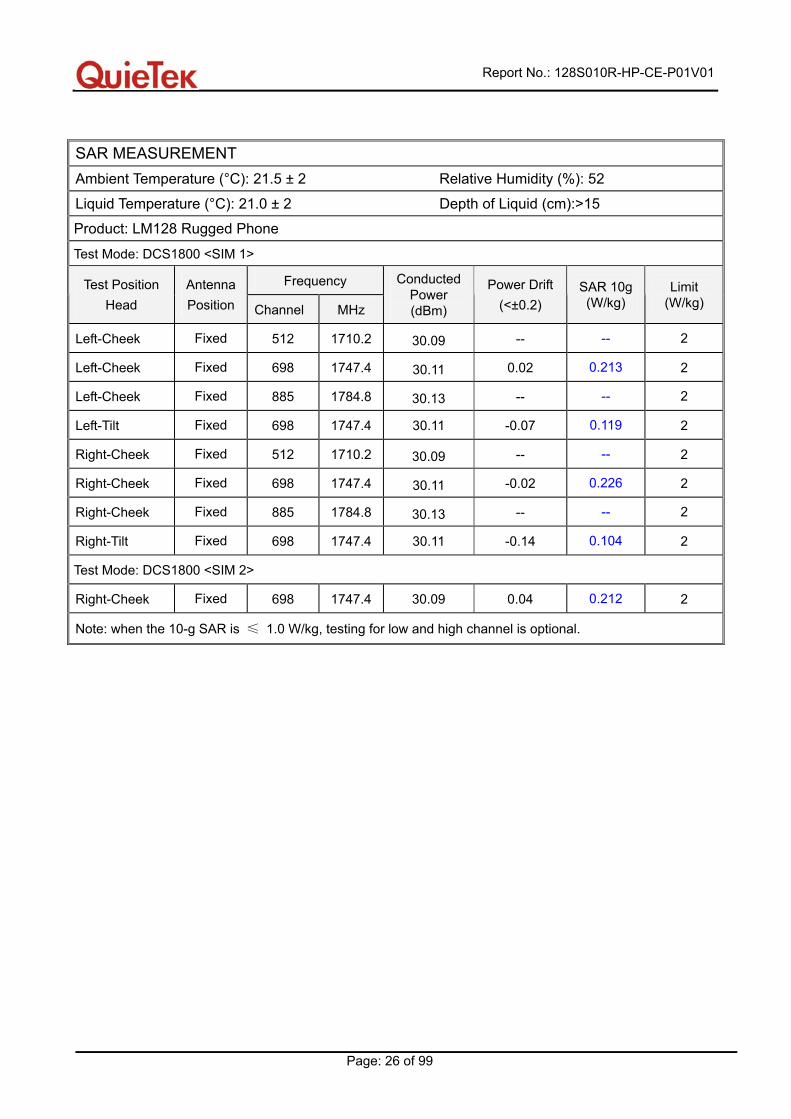
Page: 26 of 99
SAR MEASUREMENT Ambient Temperature (°C): 21.5 ± 2 Relative Humidity (%): 52
Liquid Temperature (°C): 21.0 ± 2 Depth of Liquid (cm):>15
Product: LM128 Rugged Phone
Test Mode: DCS1800 <SIM 1>
Frequency Test Position Head
AntennaPosition Channel MHz
Conducted Power (dBm)
Power Drift (<±0.2)
SAR 10g (W/kg)
Limit (W/kg)
Left-Cheek Fixed 512 1710.2 30.09 -- -- 2
Left-Cheek Fixed 698 1747.4 30.11 0.02 0.213 2
Left-Cheek Fixed 885 1784.8 30.13 -- -- 2
Left-Tilt Fixed 698 1747.4 30.11 -0.07 0.119 2
Right-Cheek Fixed 512 1710.2 30.09 -- -- 2
Right-Cheek Fixed 698 1747.4 30.11 -0.02 0.226 2
Right-Cheek Fixed 885 1784.8 30.13 -- -- 2
Right-Tilt Fixed 698 1747.4 30.11 -0.14 0.104 2
Test Mode: DCS1800 <SIM 2>
Right-Cheek Fixed 698 1747.4 30.09 0.04 0.212 2
Note: when the 10-g SAR is ≤ 1.0 W/kg, testing for low and high channel is optional.

Report No.: 128S010R-HP-CE-P01V01
Page: 27 of 99
SAR MEASUREMENT
Ambient Temperature (°C) : 21.5 ±2 Relative Humidity (%): 52
Liquid Temperature (°C) : 21.0 ±2 Depth of Liquid (cm):>15
Product: LM128 Rugged Phone
Test Mode: DCS1800
Frequency Test Position Body
AntennaPosition Channel MHz
Separation Distance
(mm)
Conducted Power (dBm)
Power Drift
(<±0.2)
SAR 10g
(W/kg)
Limit (W/kg)
Body-worn Fixed 512 1710.2 15 30.09 -- -- 2
Body-worn Fixed 698 1747.4 15 30.11 -0.12 0.224 2
Body-worn Fixed 885 1784.8 15 30.13 -- -- 2
Test Mode: GPRS1800-2slot
Body-worn Fixed 698 1747.4 15 29.53 -0.12 0.369 2
Test Mode: GPRS1800-3slot
Body-worn Fixed 698 1747.4 15 27.96 0.13 0.407 2
Test Mode: GPRS1800-4slot
Body-worn Fixed 512 1710.2 15 26.88 -- -- 2
Body-worn Fixed 698 1747.4 15 26.93 -0.02 0.453 2
Body-worn Fixed 885 1784.8 15 26.87 -- -- 2
Body-front Fixed 698 1747.4 15 26.93 0.04 0.401 2
Body- worn (With Headset)
Fixed 698 1747.4 15 26.93 -0.01 0.441 2
Note: when the 10-g SAR is ≤ 1.0 W/kg, testing for low and high channel is optional.
Report No.: 128S010R-HP-CE-P01V01
Page: 28 of 99
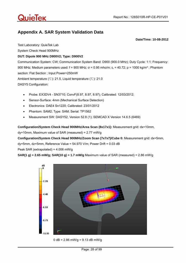
Appendix A. SAR System Validation Data Date/Time: 10-08-2012
Test Laboratory: QuieTek Lab
System Check Head 900MHz
DUT: Dipole 900 MHz D900V2; Type: D900V2
Communication System: CW; Communication System Band: D900 (900.0 MHz); Duty Cycle: 1:1; Frequency:
900 MHz; Medium parameters used: f = 900 MHz; σ = 0.95 mho/m; εr = 40.72; ρ = 1000 kg/m³ ; Phantom
section: Flat Section ; Input Power=250mW
Ambient temperature ( ): 21.5, Liquid temperature ℃ ( ): 21.0℃
DASY5 Configuration:
• Probe: EX3DV4 - SN3710; ConvF(8.97, 8.97, 8.97); Calibrated: 12/03/2012;
• Sensor-Surface: 4mm (Mechanical Surface Detection)
• Electronics: DAE4 Sn1220; Calibrated: 23/01/2012
• Phantom: SAM2; Type: SAM; Serial: TP1562
• Measurement SW: DASY52, Version 52.8 (1); SEMCAD X Version 14.6.5 (6469)
Configuration/System Check Head 900MHz/Area Scan (8x17x1): Measurement grid: dx=10mm,
dy=10mm, Maximum value of SAR (measured) = 2.77 mW/g
Configuration/System Check Head 900MHz/Zoom Scan (7x7x7)/Cube 0: Measurement grid: dx=5mm,
dy=5mm, dz=5mm, Reference Value = 54.970 V/m; Power Drift = 0.03 dB
Peak SAR (extrapolated) = 4.006 mW/g
SAR(1 g) = 2.65 mW/g; SAR(10 g) = 1.7 mW/g Maximum value of SAR (measured) = 2.86 mW/g
0 dB = 2.86 mW/g = 9.13 dB mW/g
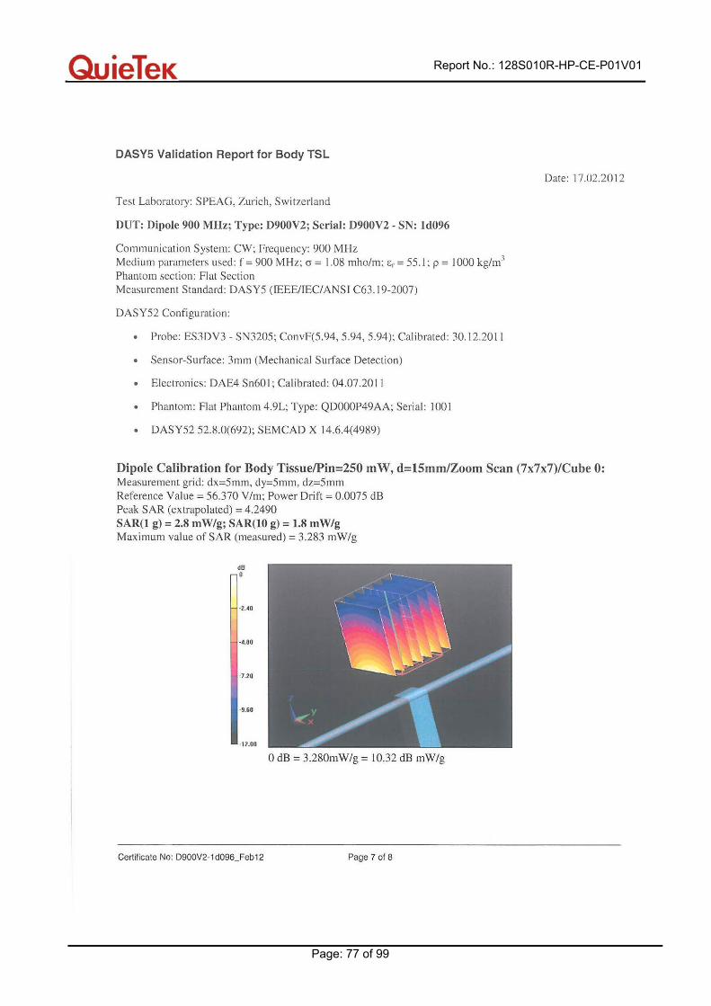
Report No.: 128S010R-HP-CE-P01V01
Page: 29 of 99
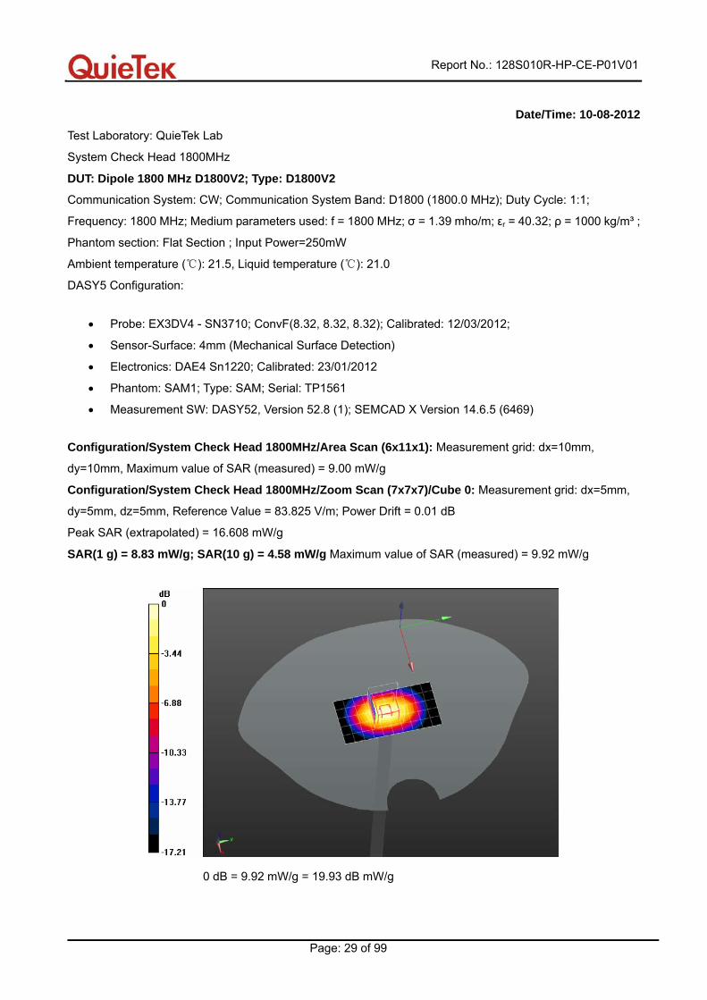
Date/Time: 10-08-2012
Test Laboratory: QuieTek Lab
System Check Head 1800MHz
DUT: Dipole 1800 MHz D1800V2; Type: D1800V2
Communication System: CW; Communication System Band: D1800 (1800.0 MHz); Duty Cycle: 1:1;
Frequency: 1800 MHz; Medium parameters used: f = 1800 MHz; σ = 1.39 mho/m; εr = 40.32; ρ = 1000 kg/m³ ;
Phantom section: Flat Section ; Input Power=250mW
Ambient temperature ( ): 21.5, Liquid temperature ( ): 21.0℃ ℃
DASY5 Configuration:
• Probe: EX3DV4 - SN3710; ConvF(8.32, 8.32, 8.32); Calibrated: 12/03/2012;
• Sensor-Surface: 4mm (Mechanical Surface Detection)
• Electronics: DAE4 Sn1220; Calibrated: 23/01/2012
• Phantom: SAM1; Type: SAM; Serial: TP1561
• Measurement SW: DASY52, Version 52.8 (1); SEMCAD X Version 14.6.5 (6469)
Configuration/System Check Head 1800MHz/Area Scan (6x11x1): Measurement grid: dx=10mm,
dy=10mm, Maximum value of SAR (measured) = 9.00 mW/g
Configuration/System Check Head 1800MHz/Zoom Scan (7x7x7)/Cube 0: Measurement grid: dx=5mm,
dy=5mm, dz=5mm, Reference Value = 83.825 V/m; Power Drift = 0.01 dB
Peak SAR (extrapolated) = 16.608 mW/g
SAR(1 g) = 8.83 mW/g; SAR(10 g) = 4.58 mW/g Maximum value of SAR (measured) = 9.92 mW/g
0 dB = 9.92 mW/g = 19.93 dB mW/g
Report No.: 128S010R-HP-CE-P01V01
Page: 30 of 99
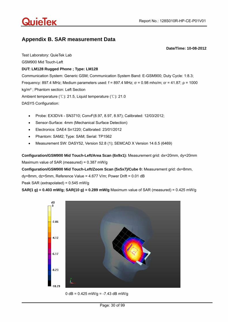
Appendix B. SAR measurement Data Date/Time: 10-08-2012
Test Laboratory: QuieTek Lab
GSM900 Mid Touch-Left
DUT: LM128 Rugged Phone ; Type: LM128
Communication System: Generic GSM; Communication System Band: E-GSM900; Duty Cycle: 1:8.3;
Frequency: 897.4 MHz; Medium parameters used: f = 897.4 MHz; σ = 0.98 mho/m; εr = 41.87; ρ = 1000
kg/m³ ; Phantom section: Left Section
Ambient temperature ( ): 21.5, Liquid temperature ( ): 21.0℃ ℃
DASY5 Configuration:
• Probe: EX3DV4 - SN3710; ConvF(8.97, 8.97, 8.97); Calibrated: 12/03/2012;
• Sensor-Surface: 4mm (Mechanical Surface Detection)
• Electronics: DAE4 Sn1220; Calibrated: 23/01/2012
• Phantom: SAM2; Type: SAM; Serial: TP1562
• Measurement SW: DASY52, Version 52.8 (1); SEMCAD X Version 14.6.5 (6469)
Configuration/GSM900 Mid Touch-Left/Area Scan (6x9x1): Measurement grid: dx=20mm, dy=20mm
Maximum value of SAR (measured) = 0.387 mW/g
Configuration/GSM900 Mid Touch-Left/Zoom Scan (5x5x7)/Cube 0: Measurement grid: dx=8mm,
dy=8mm, dz=5mm, Reference Value = 4.677 V/m; Power Drift = 0.01 dB
Peak SAR (extrapolated) = 0.545 mW/g
SAR(1 g) = 0.403 mW/g; SAR(10 g) = 0.289 mW/g Maximum value of SAR (measured) = 0.425 mW/g
0 dB = 0.425 mW/g = -7.43 dB mW/g

Report No.: 128S010R-HP-CE-P01V01
Page: 31 of 99
Date/Time: 10-08-2012
Test Laboratory: QuieTek Lab
GSM900 Mid Tilt-Left
DUT: LM128 Rugged Phone ; Type: LM128
Communication System: Generic GSM; Communication System Band: E-GSM900; Duty Cycle: 1:8.3;
Frequency: 897.4 MHz; Medium parameters used: f = 897.4 MHz; σ = 0.98 mho/m; εr = 41.87; ρ = 1000
kg/m³ ; Phantom section: Left Section
Ambient temperature ( ): 21.5, Liquid temperature ( ): 21.0℃ ℃
DASY5 Configuration:
• Probe: EX3DV4 - SN3710; ConvF(8.97, 8.97, 8.97); Calibrated: 12/03/2012;
• Sensor-Surface: 4mm (Mechanical Surface Detection)
• Electronics: DAE4 Sn1220; Calibrated: 23/01/2012
• Phantom: SAM2; Type: SAM; Serial: TP1562
• Measurement SW: DASY52, Version 52.8 (1); SEMCAD X Version 14.6.5 (6469)
Configuration/GSM900 Mid Touch-Right/Area Scan (6x9x1): Measurement grid: dx=20mm, dy=20mm
Maximum value of SAR (measured) = 0.462 mW/g
Configuration/GSM900 Mid Touch-Right/Zoom Scan (5x5x7)/Cube 0: Measurement grid: dx=8mm,
dy=8mm, dz=5mm, Reference Value = 16.441 V/m; Power Drift = -0.15 dB
Peak SAR (extrapolated) = 0.554 mW/g
SAR(1 g) = 0.452 mW/g; SAR(10 g) = 0.344 mW/g Maximum value of SAR (measured) = 0.470 mW/g
0 dB = 0.470 mW/g = -6.56 dB mW/g
Report No.: 128S010R-HP-CE-P01V01
Page: 32 of 99
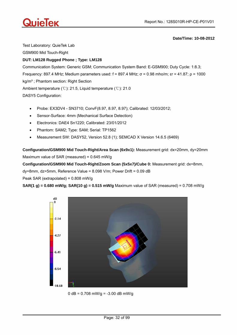
Date/Time: 10-08-2012
Test Laboratory: QuieTek Lab
GSM900 Mid Touch-Right
DUT: LM128 Rugged Phone ; Type: LM128
Communication System: Generic GSM; Communication System Band: E-GSM900; Duty Cycle: 1:8.3;
Frequency: 897.4 MHz; Medium parameters used: f = 897.4 MHz; σ = 0.98 mho/m; εr = 41.87; ρ = 1000
kg/m³ ; Phantom section: Right Section
Ambient temperature ( ): 21.5, Liquid temperat℃ ure ( ): 21.0℃
DASY5 Configuration:
• Probe: EX3DV4 - SN3710; ConvF(8.97, 8.97, 8.97); Calibrated: 12/03/2012;
• Sensor-Surface: 4mm (Mechanical Surface Detection)
• Electronics: DAE4 Sn1220; Calibrated: 23/01/2012
• Phantom: SAM2; Type: SAM; Serial: TP1562
• Measurement SW: DASY52, Version 52.8 (1); SEMCAD X Version 14.6.5 (6469)
Configuration/GSM900 Mid Touch-Right/Area Scan (6x9x1): Measurement grid: dx=20mm, dy=20mm
Maximum value of SAR (measured) = 0.645 mW/g
Configuration/GSM900 Mid Touch-Right/Zoom Scan (5x5x7)/Cube 0: Measurement grid: dx=8mm,
dy=8mm, dz=5mm, Reference Value = 8.098 V/m; Power Drift = 0.09 dB
Peak SAR (extrapolated) = 0.808 mW/g
SAR(1 g) = 0.680 mW/g; SAR(10 g) = 0.515 mW/g Maximum value of SAR (measured) = 0.708 mW/g
0 dB = 0.708 mW/g = -3.00 dB mW/g
Report No.: 128S010R-HP-CE-P01V01
Page: 33 of 99
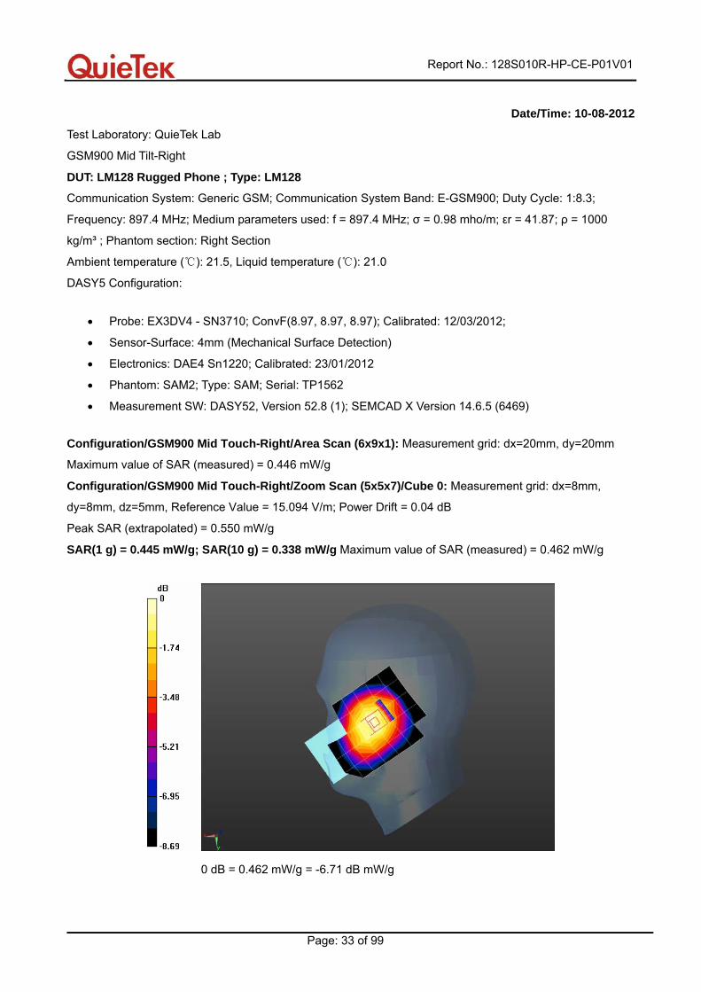
Date/Time: 10-08-2012
Test Laboratory: QuieTek Lab
GSM900 Mid Tilt-Right
DUT: LM128 Rugged Phone ; Type: LM128
Communication System: Generic GSM; Communication System Band: E-GSM900; Duty Cycle: 1:8.3;
Frequency: 897.4 MHz; Medium parameters used: f = 897.4 MHz; σ = 0.98 mho/m; εr = 41.87; ρ = 1000
kg/m³ ; Phantom section: Right Section
Ambient temperature ( ): 21.5, Liquid temperature ( ): 21.0℃ ℃
DASY5 Configuration:
• Probe: EX3DV4 - SN3710; ConvF(8.97, 8.97, 8.97); Calibrated: 12/03/2012;
• Sensor-Surface: 4mm (Mechanical Surface Detection)
• Electronics: DAE4 Sn1220; Calibrated: 23/01/2012
• Phantom: SAM2; Type: SAM; Serial: TP1562
• Measurement SW: DASY52, Version 52.8 (1); SEMCAD X Version 14.6.5 (6469)
Configuration/GSM900 Mid Touch-Right/Area Scan (6x9x1): Measurement grid: dx=20mm, dy=20mm
Maximum value of SAR (measured) = 0.446 mW/g
Configuration/GSM900 Mid Touch-Right/Zoom Scan (5x5x7)/Cube 0: Measurement grid: dx=8mm,
dy=8mm, dz=5mm, Reference Value = 15.094 V/m; Power Drift = 0.04 dB
Peak SAR (extrapolated) = 0.550 mW/g
SAR(1 g) = 0.445 mW/g; SAR(10 g) = 0.338 mW/g Maximum value of SAR (measured) = 0.462 mW/g
0 dB = 0.462 mW/g = -6.71 dB mW/g
Report No.: 128S010R-HP-CE-P01V01
Page: 34 of 99
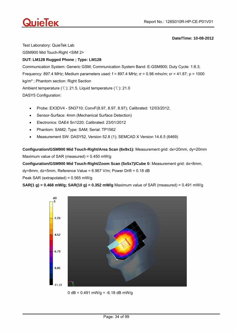
Date/Time: 10-08-2012
Test Laboratory: QuieTek Lab
GSM900 Mid Touch-Right <SIM 2>
DUT: LM128 Rugged Phone ; Type: LM128
Communication System: Generic GSM; Communication System Band: E-GSM900; Duty Cycle: 1:8.3;
Frequency: 897.4 MHz; Medium parameters used: f = 897.4 MHz; σ = 0.98 mho/m; εr = 41.87; ρ = 1000
kg/m³ ; Phantom section: Right Section
Ambient temperature ( ): 21.5, Liquid temperature ( ): 21.0℃ ℃
DASY5 Configuration:
• Probe: EX3DV4 - SN3710; ConvF(8.97, 8.97, 8.97); Calibrated: 12/03/2012;
• Sensor-Surface: 4mm (Mechanical Surface Detection)
• Electronics: DAE4 Sn1220; Calibrated: 23/01/2012
• Phantom: SAM2; Type: SAM; Serial: TP1562
• Measurement SW: DASY52, Version 52.8 (1); SEMCAD X Version 14.6.5 (6469)
Configuration/GSM900 Mid Touch-Right/Area Scan (6x9x1): Measurement grid: dx=20mm, dy=20mm
Maximum value of SAR (measured) = 0.450 mW/g
Configuration/GSM900 Mid Touch-Right/Zoom Scan (5x5x7)/Cube 0: Measurement grid: dx=8mm,
dy=8mm, dz=5mm, Reference Value = 6.967 V/m; Power Drift = 0.18 dB
Peak SAR (extrapolated) = 0.565 mW/g
SAR(1 g) = 0.468 mW/g; SAR(10 g) = 0.352 mW/g Maximum value of SAR (measured) = 0.491 mW/g
0 dB = 0.491 mW/g = -6.18 dB mW/g
Report No.: 128S010R-HP-CE-P01V01
Page: 35 of 99
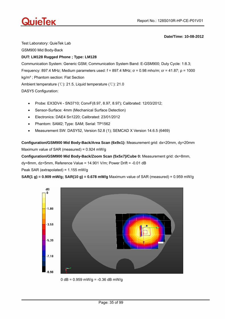
Date/Time: 10-08-2012
Test Laboratory: QuieTek Lab
GSM900 Mid Body-Back
DUT: LM128 Rugged Phone ; Type: LM128
Communication System: Generic GSM; Communication System Band: E-GSM900; Duty Cycle: 1:8.3;
Frequency: 897.4 MHz; Medium parameters used: f = 897.4 MHz; σ = 0.98 mho/m; εr = 41.87; ρ = 1000
kg/m³ ; Phantom section: Flat Section
Ambient temperature ( ): 21.5, Liquid temperature℃ ( ): 21.0℃
DASY5 Configuration:
• Probe: EX3DV4 - SN3710; ConvF(8.97, 8.97, 8.97); Calibrated: 12/03/2012;
• Sensor-Surface: 4mm (Mechanical Surface Detection)
• Electronics: DAE4 Sn1220; Calibrated: 23/01/2012
• Phantom: SAM2; Type: SAM; Serial: TP1562
• Measurement SW: DASY52, Version 52.8 (1); SEMCAD X Version 14.6.5 (6469)
Configuration/GSM900 Mid Body-Back/Area Scan (6x9x1): Measurement grid: dx=20mm, dy=20mm
Maximum value of SAR (measured) = 0.924 mW/g
Configuration/GSM900 Mid Body-Back/Zoom Scan (5x5x7)/Cube 0: Measurement grid: dx=8mm,
dy=8mm, dz=5mm, Reference Value = 14.901 V/m; Power Drift = -0.01 dB
Peak SAR (extrapolated) = 1.155 mW/g
SAR(1 g) = 0.909 mW/g; SAR(10 g) = 0.678 mW/g Maximum value of SAR (measured) = 0.959 mW/g
0 dB = 0.959 mW/g = -0.36 dB mW/g
Report No.: 128S010R-HP-CE-P01V01
Page: 36 of 99
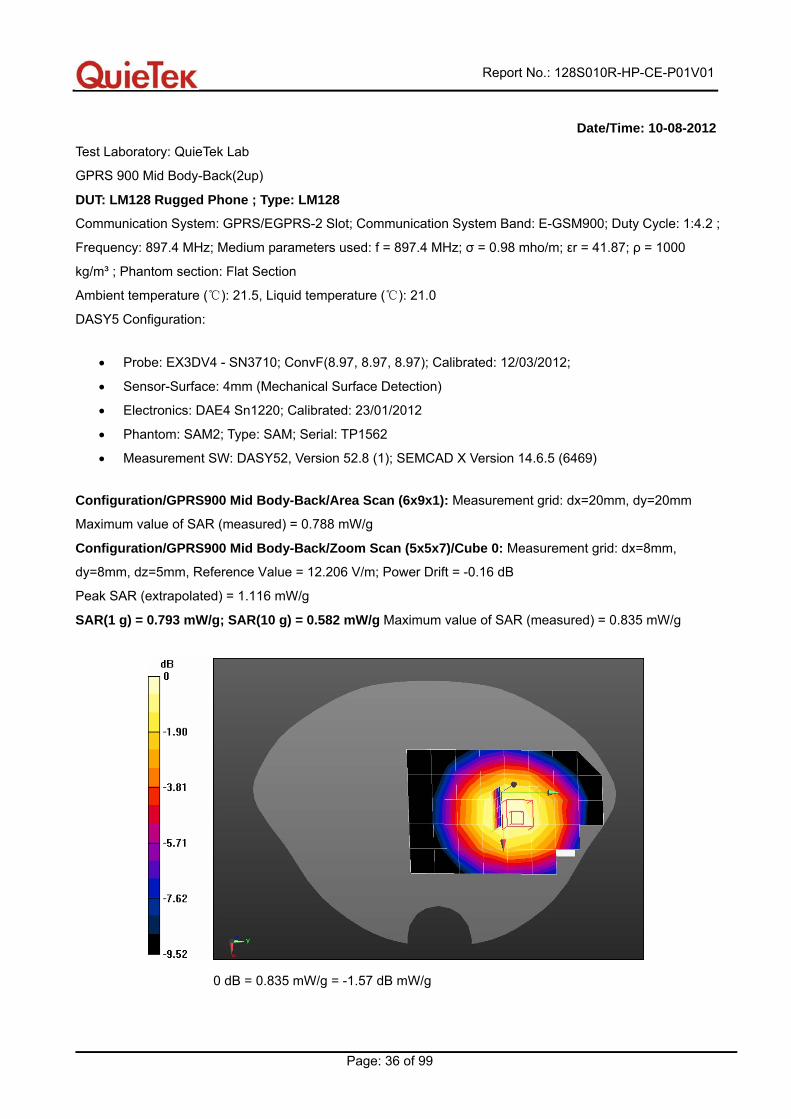
Date/Time: 10-08-2012
Test Laboratory: QuieTek Lab
GPRS 900 Mid Body-Back(2up)
DUT: LM128 Rugged Phone ; Type: LM128
Communication System: GPRS/EGPRS-2 Slot; Communication System Band: E-GSM900; Duty Cycle: 1:4.2 ;
Frequency: 897.4 MHz; Medium parameters used: f = 897.4 MHz; σ = 0.98 mho/m; εr = 41.87; ρ = 1000
kg/m³ ; Phantom section: Flat Section
Ambient temperature ( ): 21.5, Liquid temperature ( ): 21.0℃ ℃
DASY5 Configuration:
• Probe: EX3DV4 - SN3710; ConvF(8.97, 8.97, 8.97); Calibrated: 12/03/2012;
• Sensor-Surface: 4mm (Mechanical Surface Detection)
• Electronics: DAE4 Sn1220; Calibrated: 23/01/2012
• Phantom: SAM2; Type: SAM; Serial: TP1562
• Measurement SW: DASY52, Version 52.8 (1); SEMCAD X Version 14.6.5 (6469)
Configuration/GPRS900 Mid Body-Back/Area Scan (6x9x1): Measurement grid: dx=20mm, dy=20mm
Maximum value of SAR (measured) = 0.788 mW/g
Configuration/GPRS900 Mid Body-Back/Zoom Scan (5x5x7)/Cube 0: Measurement grid: dx=8mm,
dy=8mm, dz=5mm, Reference Value = 12.206 V/m; Power Drift = -0.16 dB
Peak SAR (extrapolated) = 1.116 mW/g
SAR(1 g) = 0.793 mW/g; SAR(10 g) = 0.582 mW/g Maximum value of SAR (measured) = 0.835 mW/g
0 dB = 0.835 mW/g = -1.57 dB mW/g
Report No.: 128S010R-HP-CE-P01V01
Page: 37 of 99
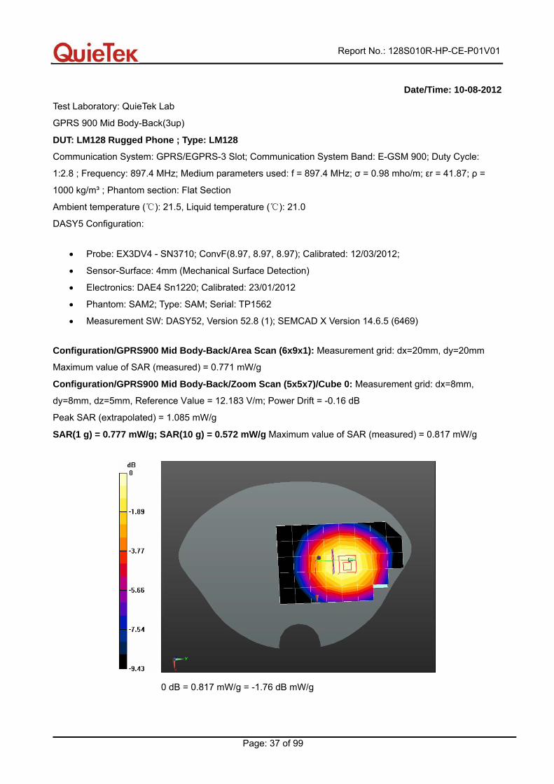
Date/Time: 10-08-2012
Test Laboratory: QuieTek Lab
GPRS 900 Mid Body-Back(3up)
DUT: LM128 Rugged Phone ; Type: LM128
Communication System: GPRS/EGPRS-3 Slot; Communication System Band: E-GSM 900; Duty Cycle:
1:2.8 ; Frequency: 897.4 MHz; Medium parameters used: f = 897.4 MHz; σ = 0.98 mho/m; εr = 41.87; ρ =
1000 kg/m³ ; Phantom section: Flat Section
Ambient temperature ( ): 21.5, Liquid temperature ( ): 21.0℃ ℃
DASY5 Configuration:
• Probe: EX3DV4 - SN3710; ConvF(8.97, 8.97, 8.97); Calibrated: 12/03/2012;
• Sensor-Surface: 4mm (Mechanical Surface Detection)
• Electronics: DAE4 Sn1220; Calibrated: 23/01/2012
• Phantom: SAM2; Type: SAM; Serial: TP1562
• Measurement SW: DASY52, Version 52.8 (1); SEMCAD X Version 14.6.5 (6469)
Configuration/GPRS900 Mid Body-Back/Area Scan (6x9x1): Measurement grid: dx=20mm, dy=20mm
Maximum value of SAR (measured) = 0.771 mW/g
Configuration/GPRS900 Mid Body-Back/Zoom Scan (5x5x7)/Cube 0: Measurement grid: dx=8mm,
dy=8mm, dz=5mm, Reference Value = 12.183 V/m; Power Drift = -0.16 dB
Peak SAR (extrapolated) = 1.085 mW/g
SAR(1 g) = 0.777 mW/g; SAR(10 g) = 0.572 mW/g Maximum value of SAR (measured) = 0.817 mW/g
0 dB = 0.817 mW/g = -1.76 dB mW/g
Report No.: 128S010R-HP-CE-P01V01
Page: 38 of 99
Date/Time: 10-08-2012
Test Laboratory: QuieTek Lab
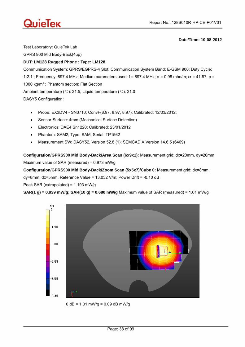
GPRS 900 Mid Body-Back(4up)
DUT: LM128 Rugged Phone ; Type: LM128
Communication System: GPRS/EGPRS-4 Slot; Communication System Band: E-GSM 900; Duty Cycle:
1:2.1 ; Frequency: 897.4 MHz; Medium parameters used: f = 897.4 MHz; σ = 0.98 mho/m; εr = 41.87; ρ =
1000 kg/m³ ; Phantom section: Flat Section
Ambient temperature ( ): 21.5, Liquid temperature ( ): 21.0℃ ℃
DASY5 Configuration:
• Probe: EX3DV4 - SN3710; ConvF(8.97, 8.97, 8.97); Calibrated: 12/03/2012;
• Sensor-Surface: 4mm (Mechanical Surface Detection)
• Electronics: DAE4 Sn1220; Calibrated: 23/01/2012
• Phantom: SAM2; Type: SAM; Serial: TP1562
• Measurement SW: DASY52, Version 52.8 (1); SEMCAD X Version 14.6.5 (6469)
Configuration/GPRS900 Mid Body-Back/Area Scan (6x9x1): Measurement grid: dx=20mm, dy=20mm
Maximum value of SAR (measured) = 0.973 mW/g
Configuration/GPRS900 Mid Body-Back/Zoom Scan (5x5x7)/Cube 0: Measurement grid: dx=8mm,
dy=8mm, dz=5mm, Reference Value = 13.032 V/m; Power Drift = -0.10 dB
Peak SAR (extrapolated) = 1.193 mW/g
SAR(1 g) = 0.939 mW/g; SAR(10 g) = 0.680 mW/g Maximum value of SAR (measured) = 1.01 mW/g
0 dB = 1.01 mW/g = 0.09 dB mW/g
Report No.: 128S010R-HP-CE-P01V01
Page: 39 of 99
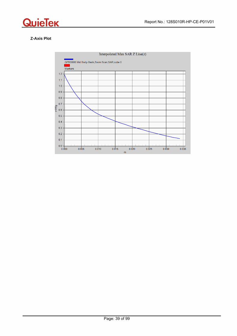
Z-Axis Plot

Report No.: 128S010R-HP-CE-P01V01
Page: 40 of 99
Date/Time: 10-08-2012
Test Laboratory: QuieTek Lab
GPRS 900 Mid Body-Front(4up)
DUT: LM128 Rugged Phone ; Type: LM128
Communication System: GPRS/EGPRS-4 Slot; Communication System Band: E-GSM 900; Duty Cycle:
1:2.1 ; Frequency: 897.4 MHz; Medium parameters used: f = 897.4 MHz; σ = 0.98 mho/m; εr = 41.87; ρ =
1000 kg/m³ ; Phantom section: Flat Section
Ambient temperature ( ): 21.5, Liquid temperatu℃ re ( ): 21.0℃
DASY5 Configuration:
• Probe: EX3DV4 - SN3710; ConvF(8.97, 8.97, 8.97); Calibrated: 12/03/2012;
• Sensor-Surface: 4mm (Mechanical Surface Detection)
• Electronics: DAE4 Sn1220; Calibrated: 23/01/2012
• Phantom: SAM2; Type: SAM; Serial: TP1562
• Measurement SW: DASY52, Version 52.8 (1); SEMCAD X Version 14.6.5 (6469)
Configuration/GPRS900 Mid Body-Front/Area Scan (6x9x1): Measurement grid: dx=20mm, dy=20mm
Maximum value of SAR (measured) = 0.756 mW/g
Configuration/GPRS900 Mid Body-Front/Zoom Scan (5x5x7)/Cube 0: Measurement grid: dx=8mm,
dy=8mm, dz=5mm, Reference Value = 10.242 V/m; Power Drift = -0.14 dB
Peak SAR (extrapolated) = 0.978 mW/g
SAR(1 g) = 0.735 mW/g; SAR(10 g) = 0.539 mW/g Maximum value of SAR (measured) = 0.784 mW/g
0 dB = 0.784 mW/g = -2.11 dB mW/g
Report No.: 128S010R-HP-CE-P01V01
Page: 41 of 99
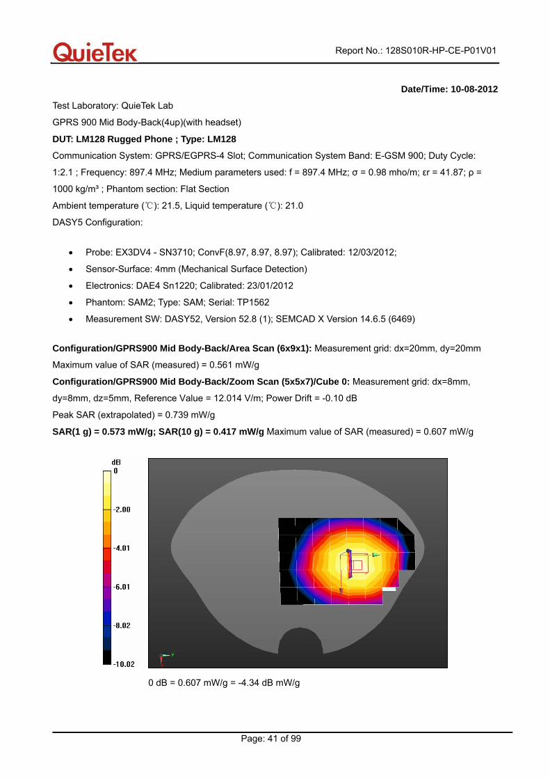
Date/Time: 10-08-2012
Test Laboratory: QuieTek Lab
GPRS 900 Mid Body-Back(4up)(with headset)
DUT: LM128 Rugged Phone ; Type: LM128
Communication System: GPRS/EGPRS-4 Slot; Communication System Band: E-GSM 900; Duty Cycle:
1:2.1 ; Frequency: 897.4 MHz; Medium parameters used: f = 897.4 MHz; σ = 0.98 mho/m; εr = 41.87; ρ =
1000 kg/m³ ; Phantom section: Flat Section
Ambient temperature ( ): 21.5, Liquid temperature ( ): 21.0℃ ℃
DASY5 Configuration:
• Probe: EX3DV4 - SN3710; ConvF(8.97, 8.97, 8.97); Calibrated: 12/03/2012;
• Sensor-Surface: 4mm (Mechanical Surface Detection)
• Electronics: DAE4 Sn1220; Calibrated: 23/01/2012
• Phantom: SAM2; Type: SAM; Serial: TP1562
• Measurement SW: DASY52, Version 52.8 (1); SEMCAD X Version 14.6.5 (6469)
Configuration/GPRS900 Mid Body-Back/Area Scan (6x9x1): Measurement grid: dx=20mm, dy=20mm
Maximum value of SAR (measured) = 0.561 mW/g
Configuration/GPRS900 Mid Body-Back/Zoom Scan (5x5x7)/Cube 0: Measurement grid: dx=8mm,
dy=8mm, dz=5mm, Reference Value = 12.014 V/m; Power Drift = -0.10 dB
Peak SAR (extrapolated) = 0.739 mW/g
SAR(1 g) = 0.573 mW/g; SAR(10 g) = 0.417 mW/g Maximum value of SAR (measured) = 0.607 mW/g
0 dB = 0.607 mW/g = -4.34 dB mW/g
Report No.: 128S010R-HP-CE-P01V01
Page: 42 of 99
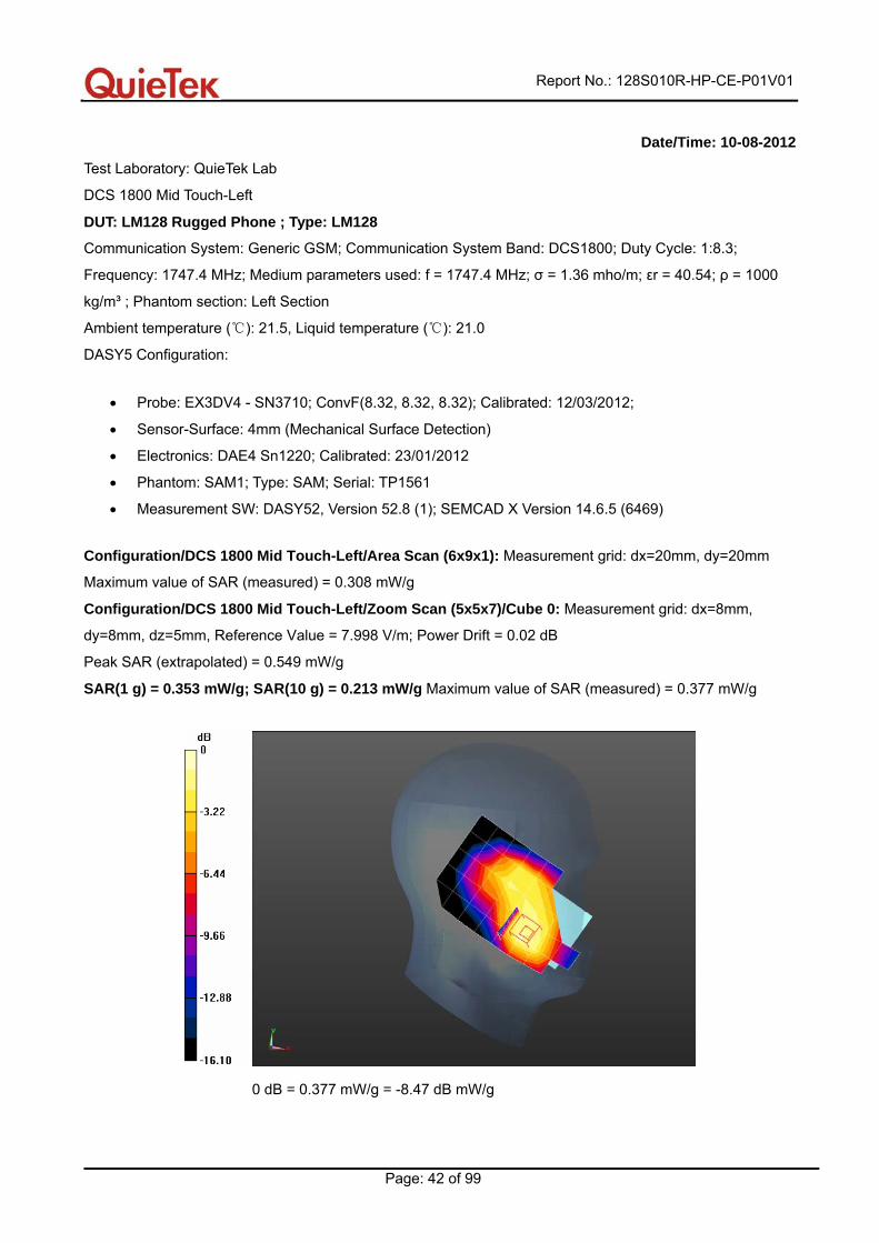
Date/Time: 10-08-2012
Test Laboratory: QuieTek Lab
DCS 1800 Mid Touch-Left
DUT: LM128 Rugged Phone ; Type: LM128
Communication System: Generic GSM; Communication System Band: DCS1800; Duty Cycle: 1:8.3;
Frequency: 1747.4 MHz; Medium parameters used: f = 1747.4 MHz; σ = 1.36 mho/m; εr = 40.54; ρ = 1000
kg/m³ ; Phantom section: Left Section
Ambient temperature ( ): 21.5, Liquid temperature ( ): 21.0℃ ℃
DASY5 Configuration:
• Probe: EX3DV4 - SN3710; ConvF(8.32, 8.32, 8.32); Calibrated: 12/03/2012;
• Sensor-Surface: 4mm (Mechanical Surface Detection)
• Electronics: DAE4 Sn1220; Calibrated: 23/01/2012
• Phantom: SAM1; Type: SAM; Serial: TP1561
• Measurement SW: DASY52, Version 52.8 (1); SEMCAD X Version 14.6.5 (6469)
Configuration/DCS 1800 Mid Touch-Left/Area Scan (6x9x1): Measurement grid: dx=20mm, dy=20mm
Maximum value of SAR (measured) = 0.308 mW/g
Configuration/DCS 1800 Mid Touch-Left/Zoom Scan (5x5x7)/Cube 0: Measurement grid: dx=8mm,
dy=8mm, dz=5mm, Reference Value = 7.998 V/m; Power Drift = 0.02 dB
Peak SAR (extrapolated) = 0.549 mW/g
SAR(1 g) = 0.353 mW/g; SAR(10 g) = 0.213 mW/g Maximum value of SAR (measured) = 0.377 mW/g
0 dB = 0.377 mW/g = -8.47 dB mW/g
Report No.: 128S010R-HP-CE-P01V01
Page: 43 of 99
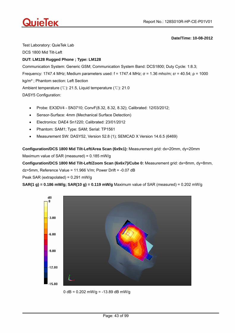
Date/Time: 10-08-2012
Test Laboratory: QuieTek Lab
DCS 1800 Mid Tilt-Left
DUT: LM128 Rugged Phone ; Type: LM128
Communication System: Generic GSM; Communication System Band: DCS1800; Duty Cycle: 1:8.3;
Frequency: 1747.4 MHz; Medium parameters used: f = 1747.4 MHz; σ = 1.36 mho/m; εr = 40.54; ρ = 1000
kg/m³ ; Phantom section: Left Section
Ambient temperature ( ): 21.5, Liquid temperature ( ): 21.0℃ ℃
DASY5 Configuration:
• Probe: EX3DV4 - SN3710; ConvF(8.32, 8.32, 8.32); Calibrated: 12/03/2012;
• Sensor-Surface: 4mm (Mechanical Surface Detection)
• Electronics: DAE4 Sn1220; Calibrated: 23/01/2012
• Phantom: SAM1; Type: SAM; Serial: TP1561
• Measurement SW: DASY52, Version 52.8 (1); SEMCAD X Version 14.6.5 (6469)
Configuration/DCS 1800 Mid Tilt-Left/Area Scan (6x9x1): Measurement grid: dx=20mm, dy=20mm
Maximum value of SAR (measured) = 0.185 mW/g
Configuration/DCS 1800 Mid Tilt-Left/Zoom Scan (6x6x7)/Cube 0: Measurement grid: dx=8mm, dy=8mm,
dz=5mm, Reference Value = 11.966 V/m; Power Drift = -0.07 dB
Peak SAR (extrapolated) = 0.291 mW/g
SAR(1 g) = 0.186 mW/g; SAR(10 g) = 0.119 mW/g Maximum value of SAR (measured) = 0.202 mW/g
0 dB = 0.202 mW/g = -13.89 dB mW/g
Report No.: 128S010R-HP-CE-P01V01
Page: 44 of 99
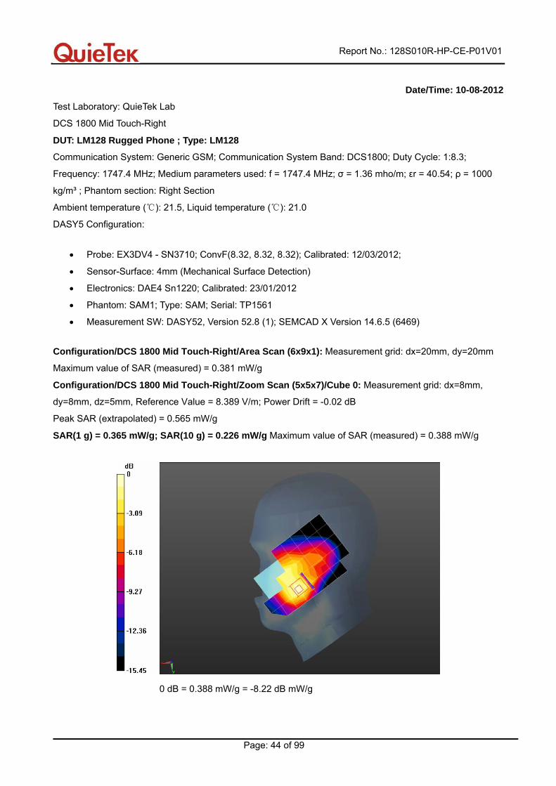
Date/Time: 10-08-2012
Test Laboratory: QuieTek Lab
DCS 1800 Mid Touch-Right
DUT: LM128 Rugged Phone ; Type: LM128
Communication System: Generic GSM; Communication System Band: DCS1800; Duty Cycle: 1:8.3;
Frequency: 1747.4 MHz; Medium parameters used: f = 1747.4 MHz; σ = 1.36 mho/m; εr = 40.54; ρ = 1000
kg/m³ ; Phantom section: Right Section
Ambient temperature ( ): 21.5, Liquid temperature ( ): 21.0℃ ℃
DASY5 Configuration:
• Probe: EX3DV4 - SN3710; ConvF(8.32, 8.32, 8.32); Calibrated: 12/03/2012;
• Sensor-Surface: 4mm (Mechanical Surface Detection)
• Electronics: DAE4 Sn1220; Calibrated: 23/01/2012
• Phantom: SAM1; Type: SAM; Serial: TP1561
• Measurement SW: DASY52, Version 52.8 (1); SEMCAD X Version 14.6.5 (6469)
Configuration/DCS 1800 Mid Touch-Right/Area Scan (6x9x1): Measurement grid: dx=20mm, dy=20mm
Maximum value of SAR (measured) = 0.381 mW/g
Configuration/DCS 1800 Mid Touch-Right/Zoom Scan (5x5x7)/Cube 0: Measurement grid: dx=8mm,
dy=8mm, dz=5mm, Reference Value = 8.389 V/m; Power Drift = -0.02 dB
Peak SAR (extrapolated) = 0.565 mW/g
SAR(1 g) = 0.365 mW/g; SAR(10 g) = 0.226 mW/g Maximum value of SAR (measured) = 0.388 mW/g
0 dB = 0.388 mW/g = -8.22 dB mW/g
Report No.: 128S010R-HP-CE-P01V01
Page: 45 of 99
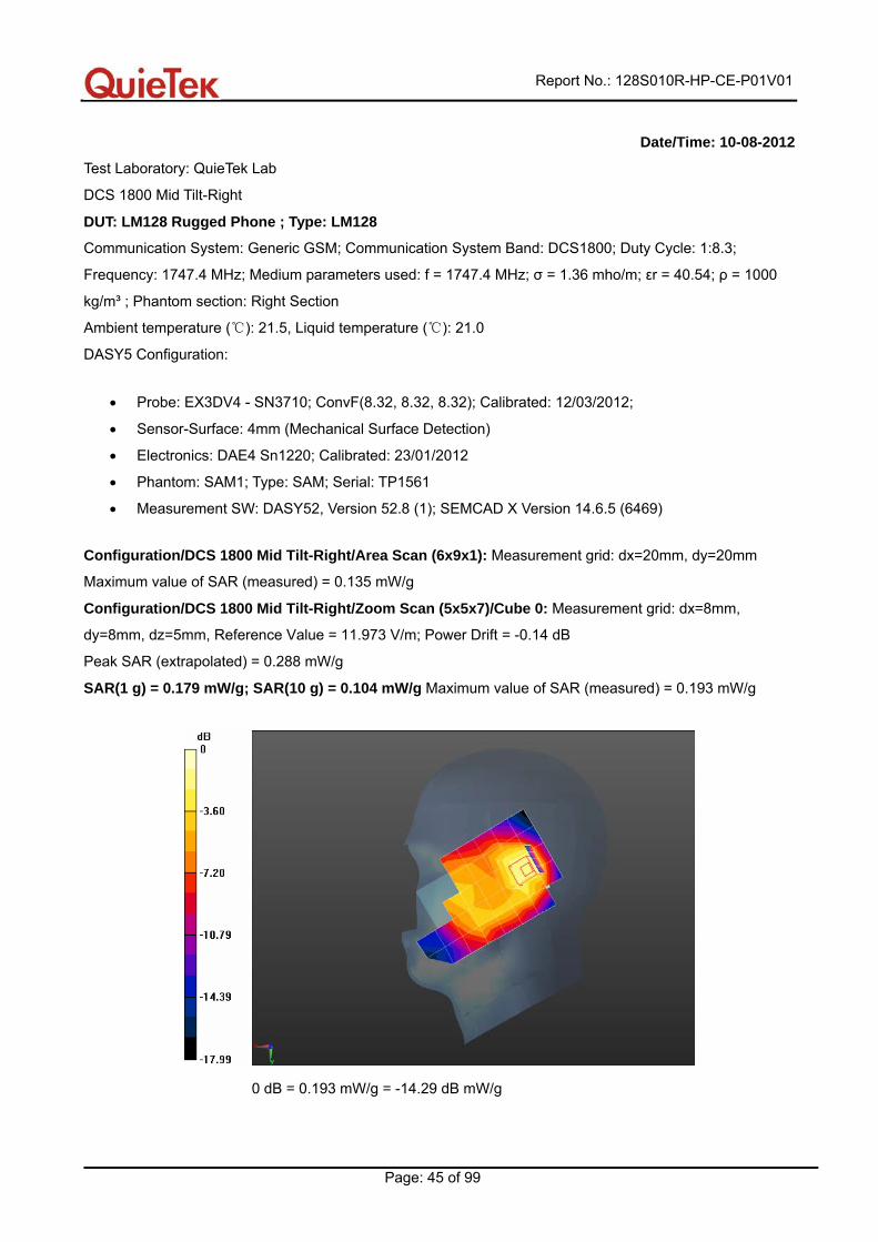
Date/Time: 10-08-2012
Test Laboratory: QuieTek Lab
DCS 1800 Mid Tilt-Right
DUT: LM128 Rugged Phone ; Type: LM128
Communication System: Generic GSM; Communication System Band: DCS1800; Duty Cycle: 1:8.3;
Frequency: 1747.4 MHz; Medium parameters used: f = 1747.4 MHz; σ = 1.36 mho/m; εr = 40.54; ρ = 1000
kg/m³ ; Phantom section: Right Section
Ambient temperature ( ): 21.5, Liquid temperature ( ): 21.0℃ ℃
DASY5 Configuration:
• Probe: EX3DV4 - SN3710; ConvF(8.32, 8.32, 8.32); Calibrated: 12/03/2012;
• Sensor-Surface: 4mm (Mechanical Surface Detection)
• Electronics: DAE4 Sn1220; Calibrated: 23/01/2012
• Phantom: SAM1; Type: SAM; Serial: TP1561
• Measurement SW: DASY52, Version 52.8 (1); SEMCAD X Version 14.6.5 (6469)
Configuration/DCS 1800 Mid Tilt-Right/Area Scan (6x9x1): Measurement grid: dx=20mm, dy=20mm
Maximum value of SAR (measured) = 0.135 mW/g
Configuration/DCS 1800 Mid Tilt-Right/Zoom Scan (5x5x7)/Cube 0: Measurement grid: dx=8mm,
dy=8mm, dz=5mm, Reference Value = 11.973 V/m; Power Drift = -0.14 dB
Peak SAR (extrapolated) = 0.288 mW/g
SAR(1 g) = 0.179 mW/g; SAR(10 g) = 0.104 mW/g Maximum value of SAR (measured) = 0.193 mW/g
0 dB = 0.193 mW/g = -14.29 dB mW/g
Report No.: 128S010R-HP-CE-P01V01
Page: 46 of 99
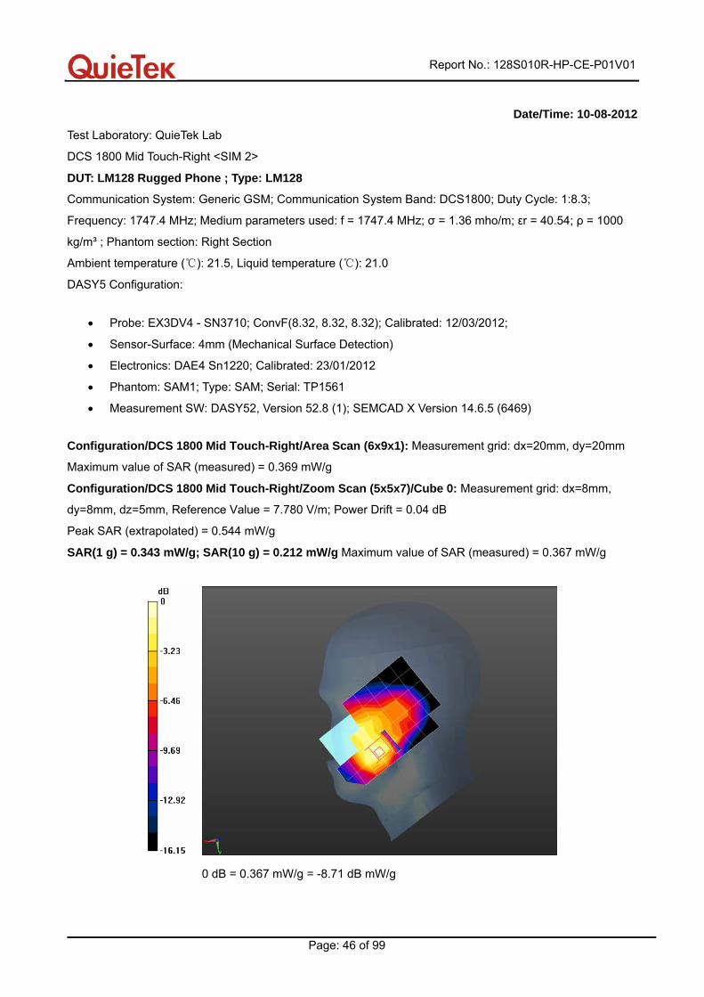
Date/Time: 10-08-2012
Test Laboratory: QuieTek Lab
DCS 1800 Mid Touch-Right <SIM 2>
DUT: LM128 Rugged Phone ; Type: LM128
Communication System: Generic GSM; Communication System Band: DCS1800; Duty Cycle: 1:8.3;
Frequency: 1747.4 MHz; Medium parameters used: f = 1747.4 MHz; σ = 1.36 mho/m; εr = 40.54; ρ = 1000
kg/m³ ; Phantom section: Right Section
Ambient temperature ( ): 21.5, Liquid temperature ( ): 21.0℃ ℃
DASY5 Configuration:
• Probe: EX3DV4 - SN3710; ConvF(8.32, 8.32, 8.32); Calibrated: 12/03/2012;
• Sensor-Surface: 4mm (Mechanical Surface Detection)
• Electronics: DAE4 Sn1220; Calibrated: 23/01/2012
• Phantom: SAM1; Type: SAM; Serial: TP1561
• Measurement SW: DASY52, Version 52.8 (1); SEMCAD X Version 14.6.5 (6469)
Configuration/DCS 1800 Mid Touch-Right/Area Scan (6x9x1): Measurement grid: dx=20mm, dy=20mm
Maximum value of SAR (measured) = 0.369 mW/g
Configuration/DCS 1800 Mid Touch-Right/Zoom Scan (5x5x7)/Cube 0: Measurement grid: dx=8mm,
dy=8mm, dz=5mm, Reference Value = 7.780 V/m; Power Drift = 0.04 dB
Peak SAR (extrapolated) = 0.544 mW/g
SAR(1 g) = 0.343 mW/g; SAR(10 g) = 0.212 mW/g Maximum value of SAR (measured) = 0.367 mW/g
0 dB = 0.367 mW/g = -8.71 dB mW/g
Report No.: 128S010R-HP-CE-P01V01
Page: 47 of 99
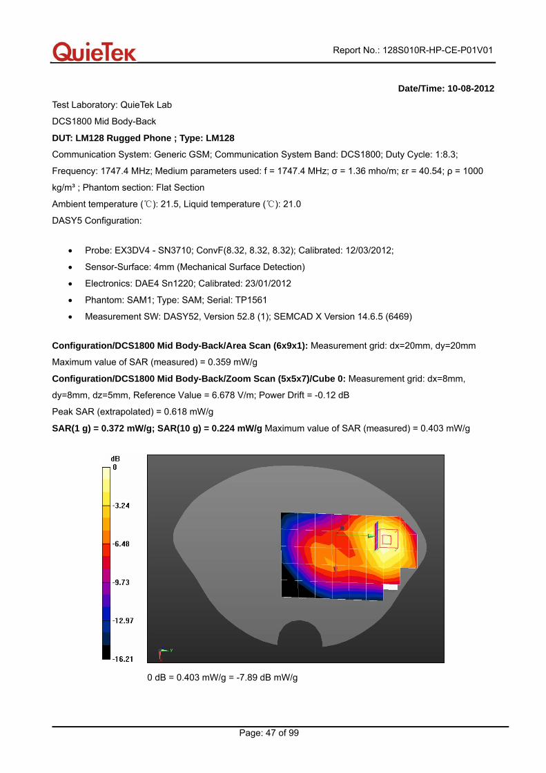
Date/Time: 10-08-2012
Test Laboratory: QuieTek Lab
DCS1800 Mid Body-Back
DUT: LM128 Rugged Phone ; Type: LM128
Communication System: Generic GSM; Communication System Band: DCS1800; Duty Cycle: 1:8.3;
Frequency: 1747.4 MHz; Medium parameters used: f = 1747.4 MHz; σ = 1.36 mho/m; εr = 40.54; ρ = 1000
kg/m³ ; Phantom section: Flat Section
Ambient temperature ( ): 21.5, Liquid temperature ( ): 21.0℃ ℃
DASY5 Configuration:
• Probe: EX3DV4 - SN3710; ConvF(8.32, 8.32, 8.32); Calibrated: 12/03/2012;
• Sensor-Surface: 4mm (Mechanical Surface Detection)
• Electronics: DAE4 Sn1220; Calibrated: 23/01/2012
• Phantom: SAM1; Type: SAM; Serial: TP1561
• Measurement SW: DASY52, Version 52.8 (1); SEMCAD X Version 14.6.5 (6469)
Configuration/DCS1800 Mid Body-Back/Area Scan (6x9x1): Measurement grid: dx=20mm, dy=20mm
Maximum value of SAR (measured) = 0.359 mW/g
Configuration/DCS1800 Mid Body-Back/Zoom Scan (5x5x7)/Cube 0: Measurement grid: dx=8mm,
dy=8mm, dz=5mm, Reference Value = 6.678 V/m; Power Drift = -0.12 dB
Peak SAR (extrapolated) = 0.618 mW/g
SAR(1 g) = 0.372 mW/g; SAR(10 g) = 0.224 mW/g Maximum value of SAR (measured) = 0.403 mW/g
0 dB = 0.403 mW/g = -7.89 dB mW/g
Report No.: 128S010R-HP-CE-P01V01
Page: 48 of 99
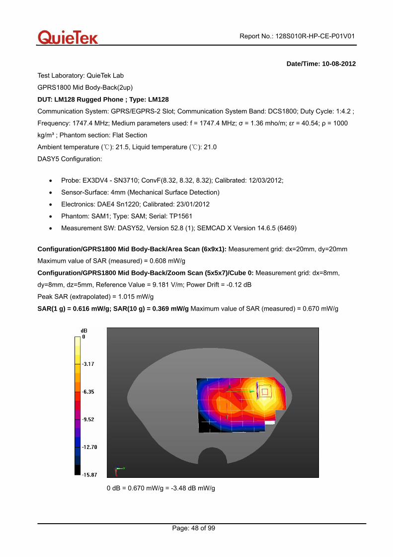
Date/Time: 10-08-2012
Test Laboratory: QuieTek Lab
GPRS1800 Mid Body-Back(2up)
DUT: LM128 Rugged Phone ; Type: LM128
Communication System: GPRS/EGPRS-2 Slot; Communication System Band: DCS1800; Duty Cycle: 1:4.2 ;
Frequency: 1747.4 MHz; Medium parameters used: f = 1747.4 MHz; σ = 1.36 mho/m; εr = 40.54; ρ = 1000
kg/m³ ; Phantom section: Flat Section
Ambient temperature ( ): 21.5, Liquid temperature ( ): 21.0℃ ℃
DASY5 Configuration:
• Probe: EX3DV4 - SN3710; ConvF(8.32, 8.32, 8.32); Calibrated: 12/03/2012;
• Sensor-Surface: 4mm (Mechanical Surface Detection)
• Electronics: DAE4 Sn1220; Calibrated: 23/01/2012
• Phantom: SAM1; Type: SAM; Serial: TP1561
• Measurement SW: DASY52, Version 52.8 (1); SEMCAD X Version 14.6.5 (6469)
Configuration/GPRS1800 Mid Body-Back/Area Scan (6x9x1): Measurement grid: dx=20mm, dy=20mm
Maximum value of SAR (measured) = 0.608 mW/g
Configuration/GPRS1800 Mid Body-Back/Zoom Scan (5x5x7)/Cube 0: Measurement grid: dx=8mm,
dy=8mm, dz=5mm, Reference Value = 9.181 V/m; Power Drift = -0.12 dB
Peak SAR (extrapolated) = 1.015 mW/g
SAR(1 g) = 0.616 mW/g; SAR(10 g) = 0.369 mW/g Maximum value of SAR (measured) = 0.670 mW/g
0 dB = 0.670 mW/g = -3.48 dB mW/g
Report No.: 128S010R-HP-CE-P01V01
Page: 49 of 99
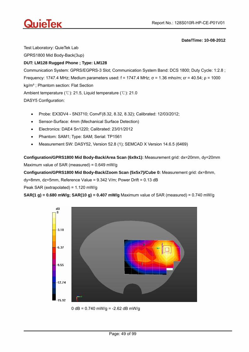
Date/Time: 10-08-2012
Test Laboratory: QuieTek Lab
GPRS1800 Mid Body-Back(3up)
DUT: LM128 Rugged Phone ; Type: LM128
Communication System: GPRS/EGPRS-3 Slot; Communication System Band: DCS 1800; Duty Cycle: 1:2.8 ;
Frequency: 1747.4 MHz; Medium parameters used: f = 1747.4 MHz; σ = 1.36 mho/m; εr = 40.54; ρ = 1000
kg/m³ ; Phantom section: Flat Section
Ambient temperature ( ): 21.5, Liquid temperature ( ): 21.0℃ ℃
DASY5 Configuration:
• Probe: EX3DV4 - SN3710; ConvF(8.32, 8.32, 8.32); Calibrated: 12/03/2012;
• Sensor-Surface: 4mm (Mechanical Surface Detection)
• Electronics: DAE4 Sn1220; Calibrated: 23/01/2012
• Phantom: SAM1; Type: SAM; Serial: TP1561
• Measurement SW: DASY52, Version 52.8 (1); SEMCAD X Version 14.6.5 (6469)
Configuration/GPRS1800 Mid Body-Back/Area Scan (6x9x1): Measurement grid: dx=20mm, dy=20mm
Maximum value of SAR (measured) = 0.649 mW/g
Configuration/GPRS1800 Mid Body-Back/Zoom Scan (5x5x7)/Cube 0: Measurement grid: dx=8mm,
dy=8mm, dz=5mm, Reference Value = 9.342 V/m; Power Drift = 0.13 dB
Peak SAR (extrapolated) = 1.120 mW/g
SAR(1 g) = 0.680 mW/g; SAR(10 g) = 0.407 mW/g Maximum value of SAR (measured) = 0.740 mW/g
0 dB = 0.740 mW/g = -2.62 dB mW/g
Report No.: 128S010R-HP-CE-P01V01
Page: 50 of 99
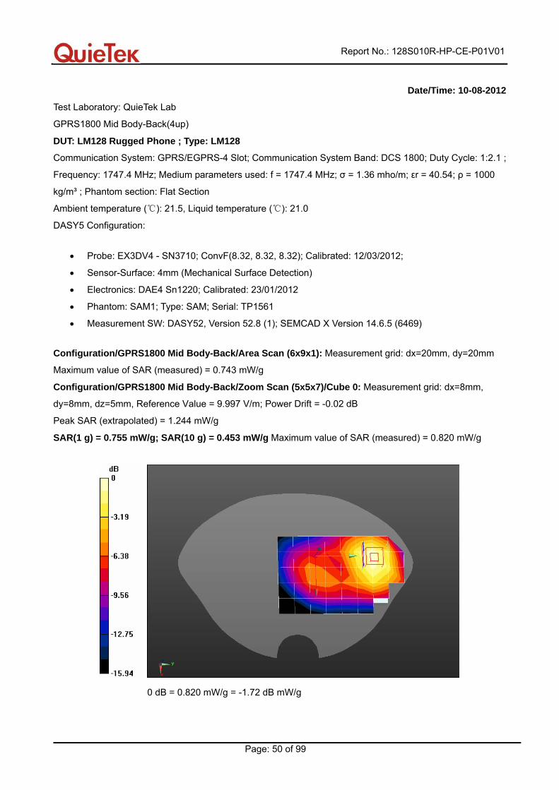
Date/Time: 10-08-2012
Test Laboratory: QuieTek Lab
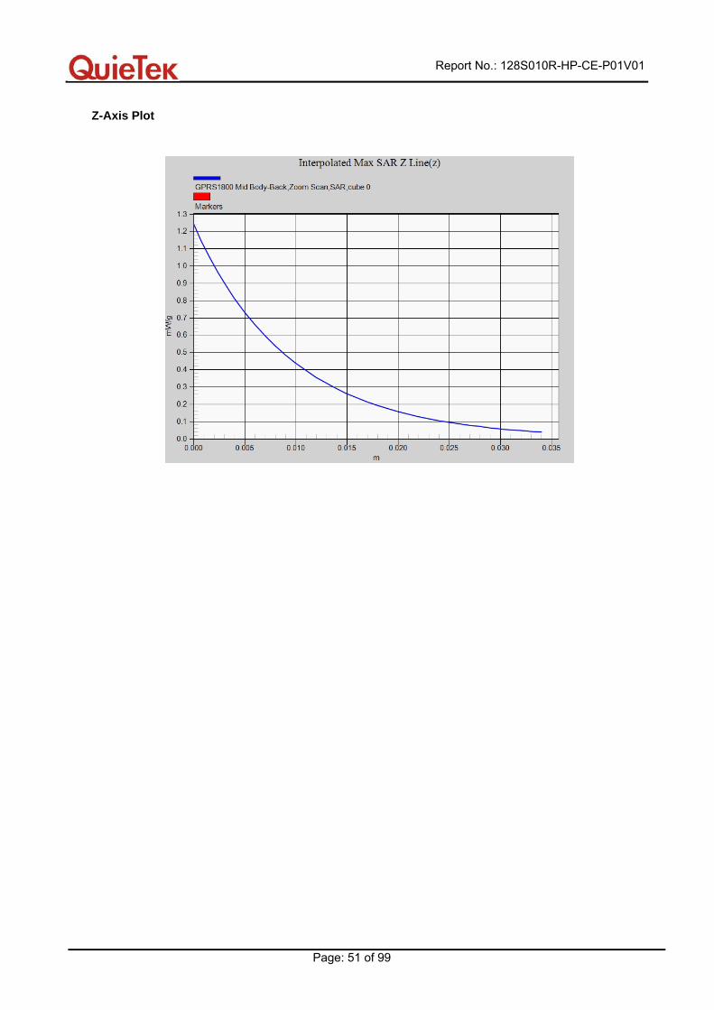
GPRS1800 Mid Body-Back(4up)
DUT: LM128 Rugged Phone ; Type: LM128
Communication System: GPRS/EGPRS-4 Slot; Communication System Band: DCS 1800; Duty Cycle: 1:2.1 ;
Frequency: 1747.4 MHz; Medium parameters used: f = 1747.4 MHz; σ = 1.36 mho/m; εr = 40.54; ρ = 1000
kg/m³ ; Phantom section: Flat Section
Ambient temperature ( ): 21.5, Liquid temperature ( ): 21.0℃ ℃
DASY5 Configuration:
• Probe: EX3DV4 - SN3710; ConvF(8.32, 8.32, 8.32); Calibrated: 12/03/2012;
• Sensor-Surface: 4mm (Mechanical Surface Detection)
• Electronics: DAE4 Sn1220; Calibrated: 23/01/2012
• Phantom: SAM1; Type: SAM; Serial: TP1561
• Measurement SW: DASY52, Version 52.8 (1); SEMCAD X Version 14.6.5 (6469)
Configuration/GPRS1800 Mid Body-Back/Area Scan (6x9x1): Measurement grid: dx=20mm, dy=20mm
Maximum value of SAR (measured) = 0.743 mW/g
Configuration/GPRS1800 Mid Body-Back/Zoom Scan (5x5x7)/Cube 0: Measurement grid: dx=8mm,
dy=8mm, dz=5mm, Reference Value = 9.997 V/m; Power Drift = -0.02 dB
Peak SAR (extrapolated) = 1.244 mW/g
SAR(1 g) = 0.755 mW/g; SAR(10 g) = 0.453 mW/g Maximum value of SAR (measured) = 0.820 mW/g
0 dB = 0.820 mW/g = -1.72 dB mW/g
Report No.: 128S010R-HP-CE-P01V01
Page: 51 of 99
Z-Axis Plot
Report No.: 128S010R-HP-CE-P01V01
Page: 52 of 99
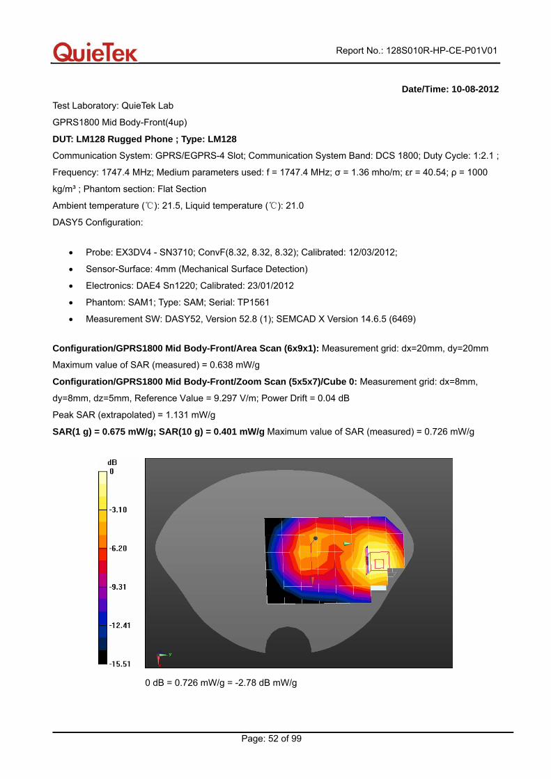
Date/Time: 10-08-2012
Test Laboratory: QuieTek Lab
GPRS1800 Mid Body-Front(4up)
DUT: LM128 Rugged Phone ; Type: LM128
Communication System: GPRS/EGPRS-4 Slot; Communication System Band: DCS 1800; Duty Cycle: 1:2.1 ;
Frequency: 1747.4 MHz; Medium parameters used: f = 1747.4 MHz; σ = 1.36 mho/m; εr = 40.54; ρ = 1000
kg/m³ ; Phantom section: Flat Section
Ambient temperature ( ): 21.5, Liquid temperature ( ): 21.0℃ ℃
DASY5 Configuration:
• Probe: EX3DV4 - SN3710; ConvF(8.32, 8.32, 8.32); Calibrated: 12/03/2012;
• Sensor-Surface: 4mm (Mechanical Surface Detection)
• Electronics: DAE4 Sn1220; Calibrated: 23/01/2012
• Phantom: SAM1; Type: SAM; Serial: TP1561
• Measurement SW: DASY52, Version 52.8 (1); SEMCAD X Version 14.6.5 (6469)
Configuration/GPRS1800 Mid Body-Front/Area Scan (6x9x1): Measurement grid: dx=20mm, dy=20mm
Maximum value of SAR (measured) = 0.638 mW/g
Configuration/GPRS1800 Mid Body-Front/Zoom Scan (5x5x7)/Cube 0: Measurement grid: dx=8mm,
dy=8mm, dz=5mm, Reference Value = 9.297 V/m; Power Drift = 0.04 dB
Peak SAR (extrapolated) = 1.131 mW/g
SAR(1 g) = 0.675 mW/g; SAR(10 g) = 0.401 mW/g Maximum value of SAR (measured) = 0.726 mW/g
0 dB = 0.726 mW/g = -2.78 dB mW/g
Report No.: 128S010R-HP-CE-P01V01
Page: 53 of 99
Date/Time: 10-08-2012
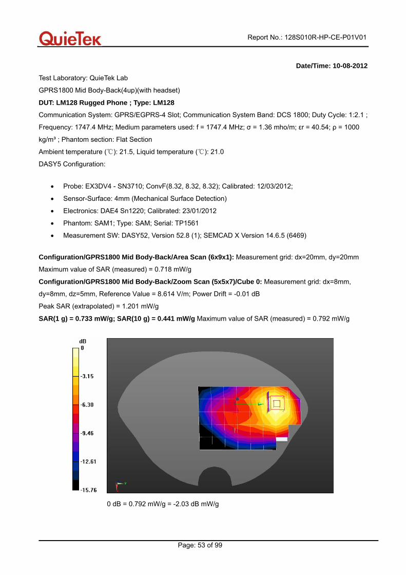
Test Laboratory: QuieTek Lab
GPRS1800 Mid Body-Back(4up)(with headset)
DUT: LM128 Rugged Phone ; Type: LM128
Communication System: GPRS/EGPRS-4 Slot; Communication System Band: DCS 1800; Duty Cycle: 1:2.1 ;
Frequency: 1747.4 MHz; Medium parameters used: f = 1747.4 MHz; σ = 1.36 mho/m; εr = 40.54; ρ = 1000
kg/m³ ; Phantom section: Flat Section
Ambient temperature ( ): 21.5, Liquid temperature ( ): 21.0℃ ℃
DASY5 Configuration:
• Probe: EX3DV4 - SN3710; ConvF(8.32, 8.32, 8.32); Calibrated: 12/03/2012;
• Sensor-Surface: 4mm (Mechanical Surface Detection)
• Electronics: DAE4 Sn1220; Calibrated: 23/01/2012
• Phantom: SAM1; Type: SAM; Serial: TP1561
• Measurement SW: DASY52, Version 52.8 (1); SEMCAD X Version 14.6.5 (6469)
Configuration/GPRS1800 Mid Body-Back/Area Scan (6x9x1): Measurement grid: dx=20mm, dy=20mm
Maximum value of SAR (measured) = 0.718 mW/g
Configuration/GPRS1800 Mid Body-Back/Zoom Scan (5x5x7)/Cube 0: Measurement grid: dx=8mm,
dy=8mm, dz=5mm, Reference Value = 8.614 V/m; Power Drift = -0.01 dB
Peak SAR (extrapolated) = 1.201 mW/g
SAR(1 g) = 0.733 mW/g; SAR(10 g) = 0.441 mW/g Maximum value of SAR (measured) = 0.792 mW/g
0 dB = 0.792 mW/g = -2.03 dB mW/g
Report No.: 128S010R-HP-CE-P01V01
Page: 54 of 99
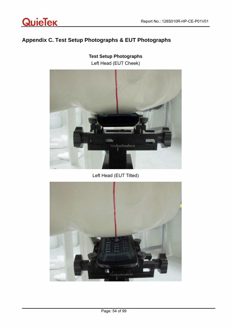
Appendix C. Test Setup Photographs & EUT Photographs
Test Setup Photographs Left Head (EUT Cheek)
Left Head (EUT Tilted)
Report No.: 128S010R-HP-CE-P01V01
Page: 55 of 99
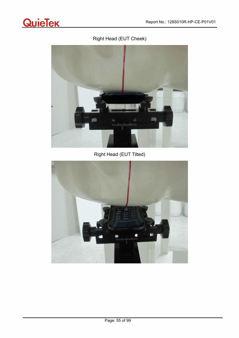
Right Head (EUT Cheek)
Right Head (EUT Tilted)
Report No.: 128S010R-HP-CE-P01V01
Page: 56 of 99
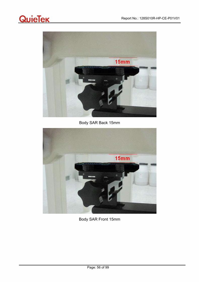
Body SAR Back 15mm
Body SAR Front 15mm
Report No.: 128S010R-HP-CE-P01V01
Page: 57 of 99
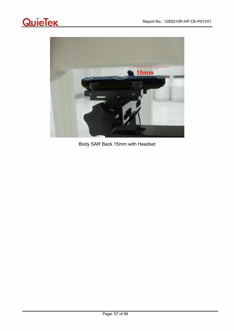
Body SAR Back 15mm with Headset
Report No.: 128S010R-HP-CE-P01V01
Page: 58 of 99
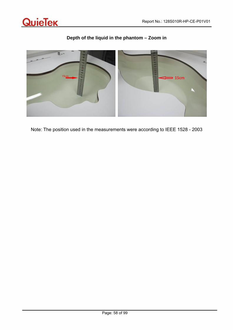
Depth of the liquid in the phantom – Zoom in
Note: The position used in the measurements were according to IEEE 1528 - 2003
Report No.: 128S010R-HP-CE-P01V01
Page: 59 of 99
EUT Photographs
Report No.: 128S010R-HP-CE-P01V01
Page: 60 of 99
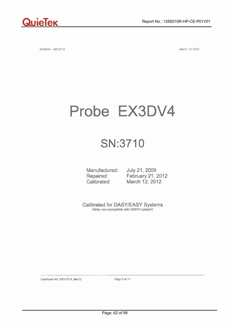
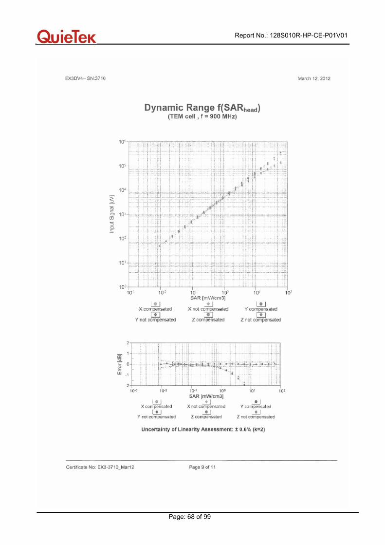
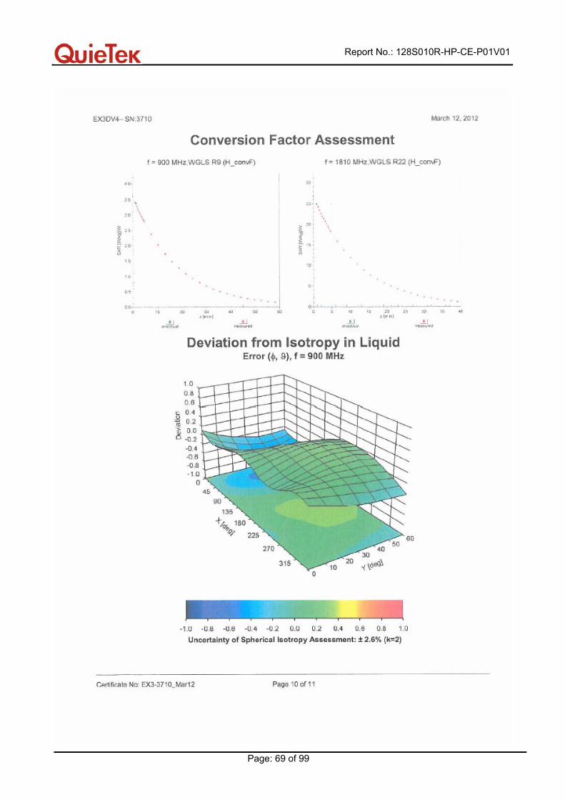
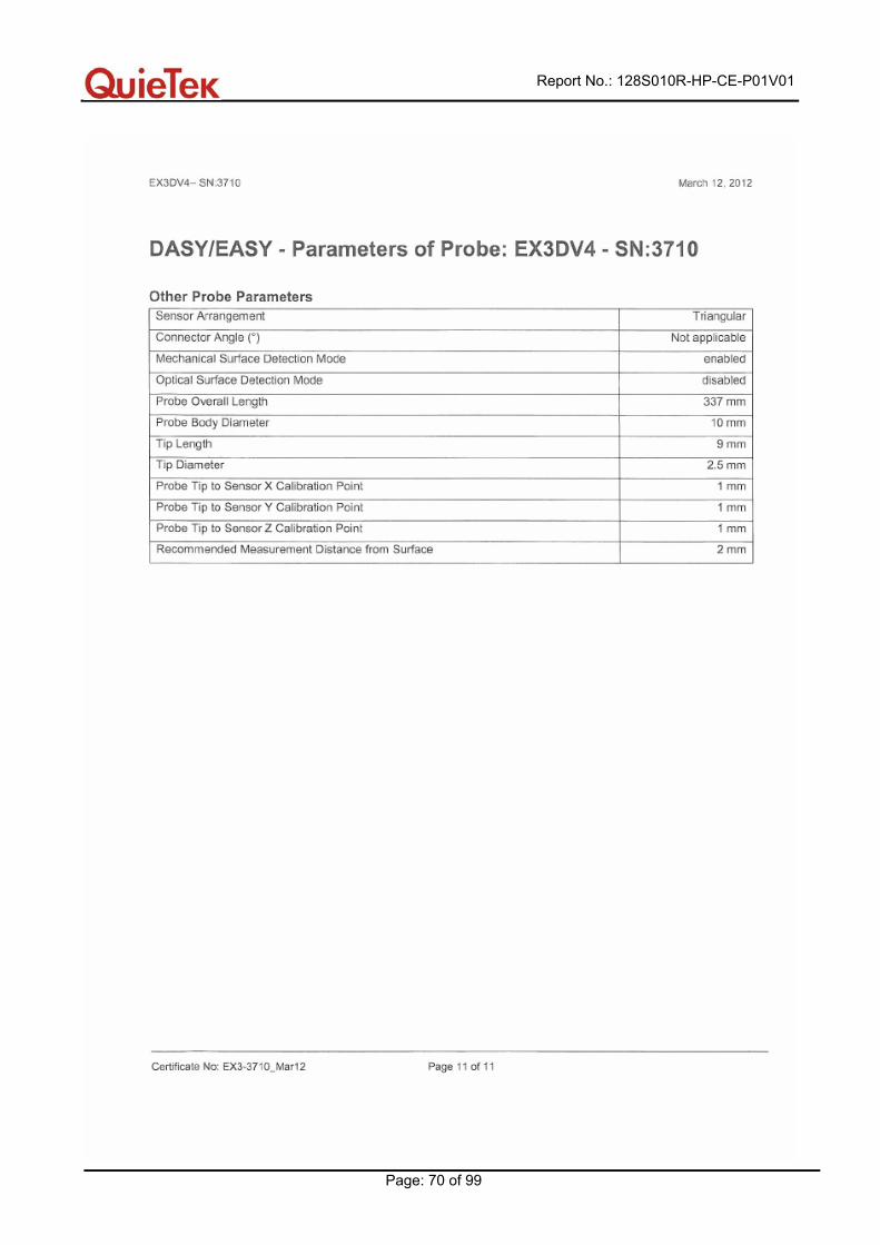
Appendix D. Probe Calibration Data

Report No.: 128S010R-HP-CE-P01V01
Page: 61 of 99
Report No.: 128S010R-HP-CE-P01V01
Page: 62 of 99
Report No.: 128S010R-HP-CE-P01V01
Page: 63 of 99
Report No.: 128S010R-HP-CE-P01V01
Page: 64 of 99
Report No.: 128S010R-HP-CE-P01V01
Page: 65 of 99
Report No.: 128S010R-HP-CE-P01V01
Page: 66 of 99
Report No.: 128S010R-HP-CE-P01V01
Page: 67 of 99
Report No.: 128S010R-HP-CE-P01V01
Page: 68 of 99
Report No.: 128S010R-HP-CE-P01V01
Page: 69 of 99
Report No.: 128S010R-HP-CE-P01V01
Page: 70 of 99
Report No.: 128S010R-HP-CE-P01V01
Page: 71 of 99
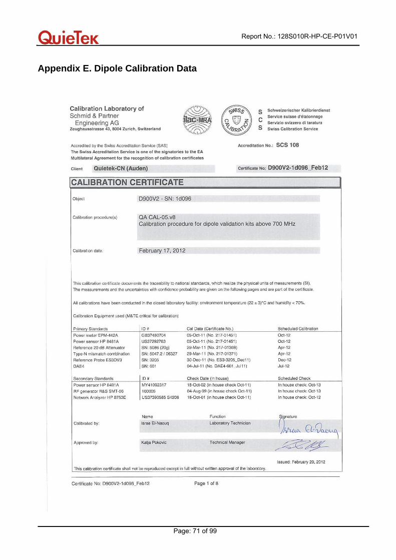
Appendix E. Dipole Calibration Data

Report No.: 128S010R-HP-CE-P01V01
Page: 72 of 99
Report No.: 128S010R-HP-CE-P01V01
Page: 73 of 99
Report No.: 128S010R-HP-CE-P01V01
Page: 74 of 99
Report No.: 128S010R-HP-CE-P01V01
Page: 75 of 99
Report No.: 128S010R-HP-CE-P01V01
Page: 76 of 99
Report No.: 128S010R-HP-CE-P01V01
Page: 77 of 99

Report No.: 128S010R-HP-CE-P01V01
Page: 78 of 99
Report No.: 128S010R-HP-CE-P01V01
Page: 79 of 99
Report No.: 128S010R-HP-CE-P01V01
Page: 80 of 99
Report No.: 128S010R-HP-CE-P01V01
Page: 81 of 99

Report No.: 128S010R-HP-CE-P01V01
Page: 82 of 99
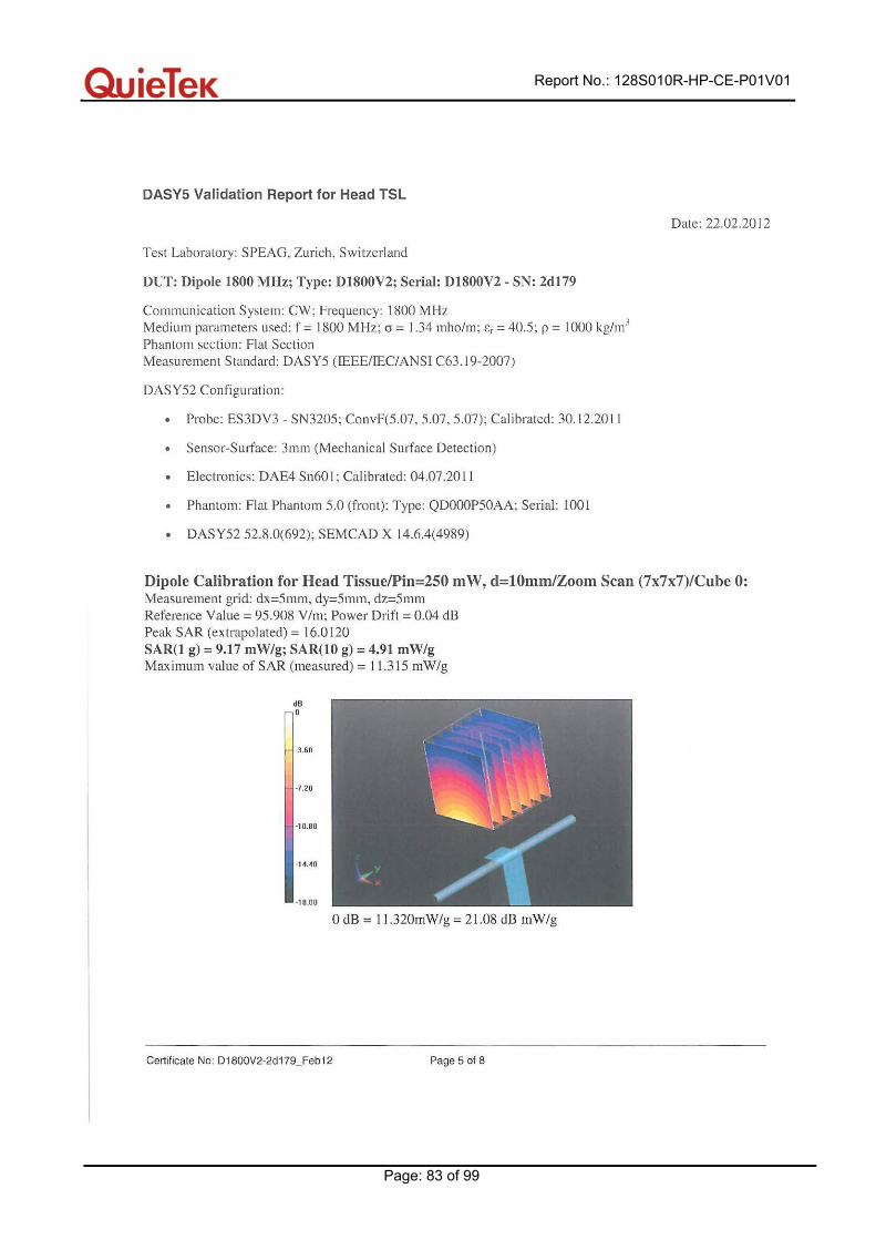
Report No.: 128S010R-HP-CE-P01V01
Page: 83 of 99
Report No.: 128S010R-HP-CE-P01V01
Page: 84 of 99

Report No.: 128S010R-HP-CE-P01V01
Page: 85 of 99
Report No.: 128S010R-HP-CE-P01V01
Page: 86 of 99

Report No.: 128S010R-HP-CE-P01V01
Page: 87 of 99
Report No.: 128S010R-HP-CE-P01V01
Page: 88 of 99
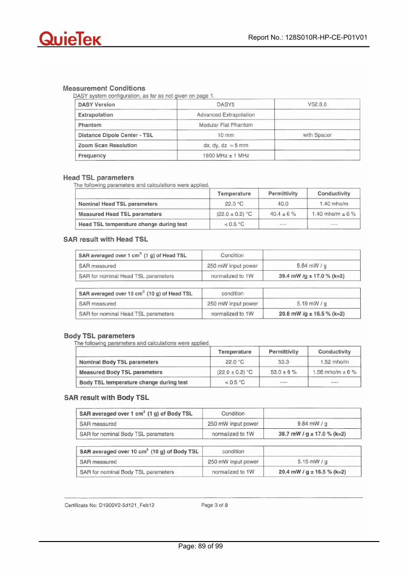
Report No.: 128S010R-HP-CE-P01V01
Page: 89 of 99

Report No.: 128S010R-HP-CE-P01V01
Page: 90 of 99
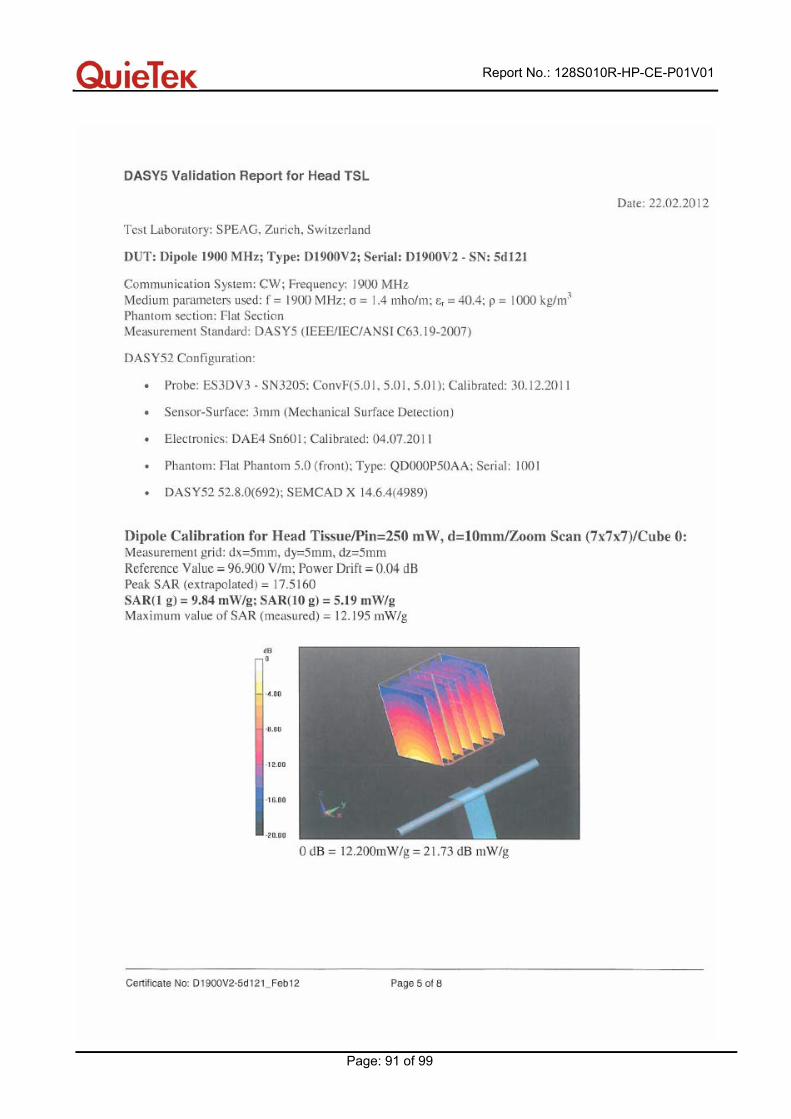
Report No.: 128S010R-HP-CE-P01V01
Page: 91 of 99
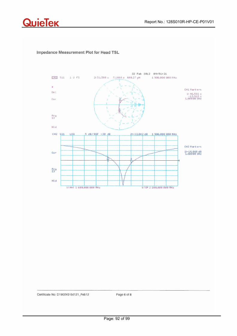
Report No.: 128S010R-HP-CE-P01V01
Page: 92 of 99

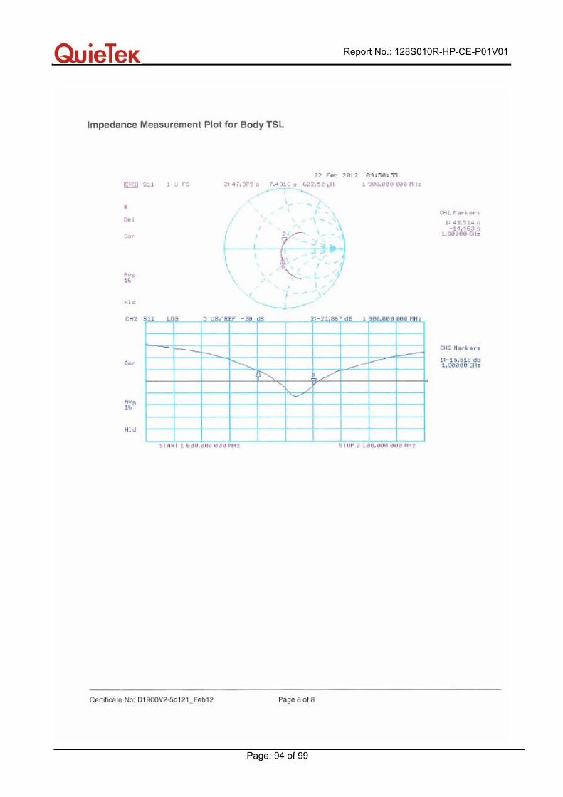
Report No.: 128S010R-HP-CE-P01V01
Page: 93 of 99
Report No.: 128S010R-HP-CE-P01V01
Page: 94 of 99
Report No.: 128S010R-HP-CE-P01V01
Page: 95 of 99
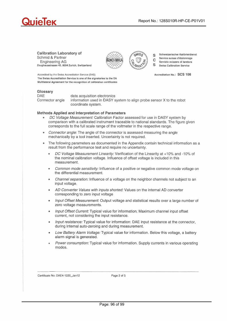
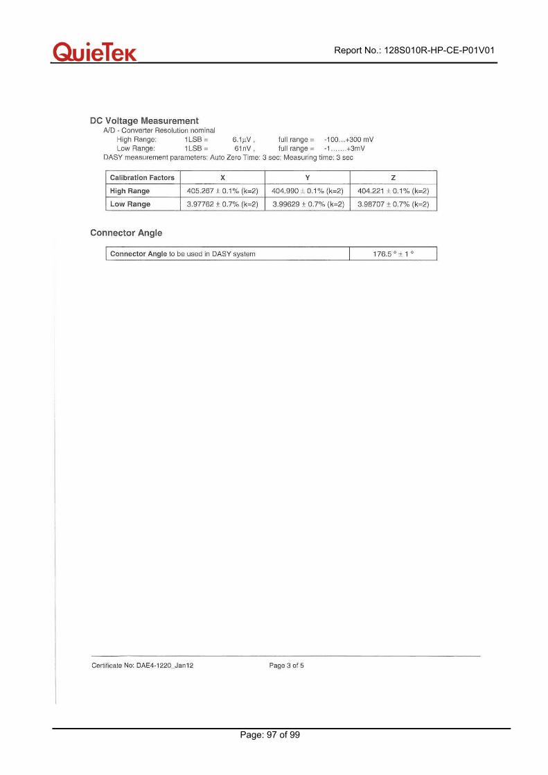
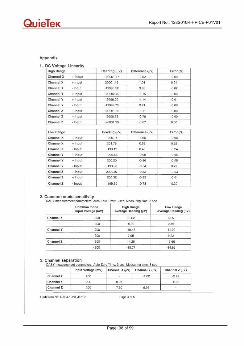
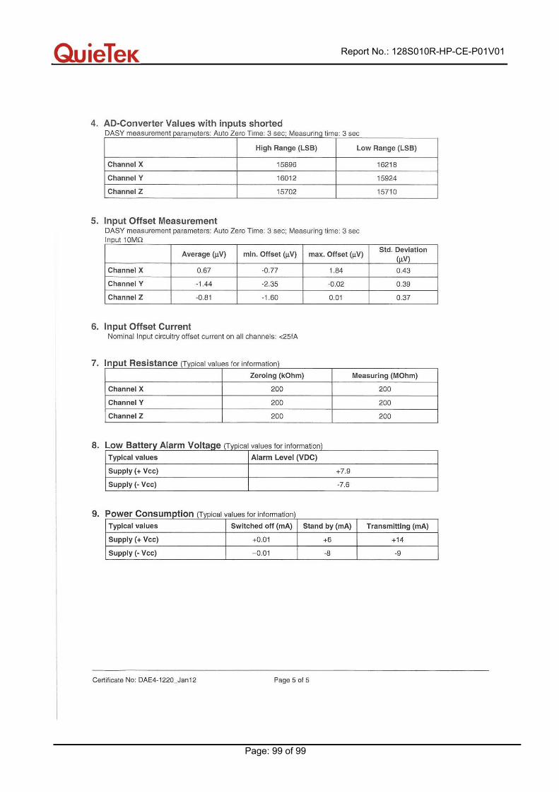
Appendix F. DAE Calibration Data
Report No.: 128S010R-HP-CE-P01V01
Page: 96 of 99
Report No.: 128S010R-HP-CE-P01V01
Page: 97 of 99
Report No.: 128S010R-HP-CE-P01V01
Page: 98 of 99
Report No.: 128S010R-HP-CE-P01V01
Page: 99 of 99