Embed Size (px)
Citation preview
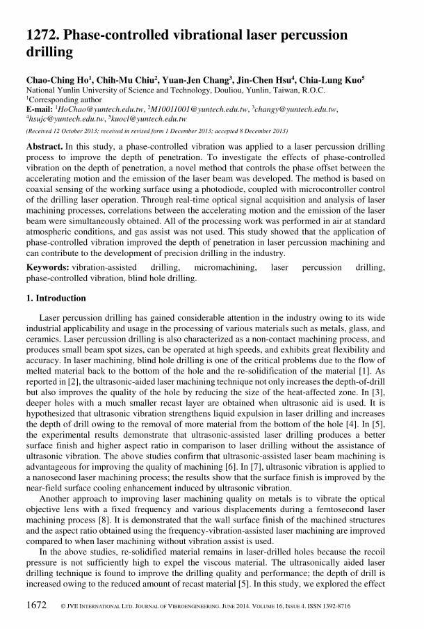
1672 © JVE INTERNATIONAL LTD. JOURNAL OF VIBROENGINEERING. JUNE 2014. VOLUME 16, ISSUE 4. ISSN 1392-8716
1272. Phase-controlled vibrational laser percussion
drilling
Chao-Ching Ho1, Chih-Mu Chiu2, Yuan-Jen Chang3, Jin-Chen Hsu4, Chia-Lung Kuo5 National Yunlin University of Science and Technology, Douliou, Yunlin, Taiwan, R.O.C. 1Corresponding author
E-mail: [email protected], [email protected], [email protected], [email protected], [email protected]
(Received 12 October 2013; received in revised form 1 December 2013; accepted 8 December 2013)
Abstract. In this study, a phase-controlled vibration was applied to a laser percussion drilling
process to improve the depth of penetration. To investigate the effects of phase-controlled
vibration on the depth of penetration, a novel method that controls the phase offset between the
accelerating motion and the emission of the laser beam was developed. The method is based on
coaxial sensing of the working surface using a photodiode, coupled with microcontroller control
of the drilling laser operation. Through real-time optical signal acquisition and analysis of laser
machining processes, correlations between the accelerating motion and the emission of the laser
beam were simultaneously obtained. All of the processing work was performed in air at standard
atmospheric conditions, and gas assist was not used. This study showed that the application of
phase-controlled vibration improved the depth of penetration in laser percussion machining and
can contribute to the development of precision drilling in the industry.
Keywords: vibration-assisted drilling, micromachining, laser percussion drilling,
phase-controlled vibration, blind hole drilling.
1. Introduction
Laser percussion drilling has gained considerable attention in the industry owing to its wide
industrial applicability and usage in the processing of various materials such as metals, glass, and
ceramics. Laser percussion drilling is also characterized as a non-contact machining process, and
produces small beam spot sizes, can be operated at high speeds, and exhibits great flexibility and
accuracy. In laser machining, blind hole drilling is one of the critical problems due to the flow of
melted material back to the bottom of the hole and the re-solidification of the material [1]. As
reported in [2], the ultrasonic-aided laser machining technique not only increases the depth-of-drill
but also improves the quality of the hole by reducing the size of the heat-affected zone. In [3],
deeper holes with a much smaller recast layer are obtained when ultrasonic aid is used. It is
hypothesized that ultrasonic vibration strengthens liquid expulsion in laser drilling and increases
the depth of drill owing to the removal of more material from the bottom of the hole [4]. In [5],
the experimental results demonstrate that ultrasonic-assisted laser drilling produces a better
surface finish and higher aspect ratio in comparison to laser drilling without the assistance of
ultrasonic vibration. The above studies confirm that ultrasonic-assisted laser beam machining is
advantageous for improving the quality of machining [6]. In [7], ultrasonic vibration is applied to
a nanosecond laser machining process; the results show that the surface finish is improved by the
near-field surface cooling enhancement induced by ultrasonic vibration.
Another approach to improving laser machining quality on metals is to vibrate the optical
objective lens with a fixed frequency and various displacements during a femtosecond laser
machining process [8]. It is demonstrated that the wall surface finish of the machined structures
and the aspect ratio obtained using the frequency-vibration-assisted laser machining are improved
compared to when laser machining without vibration assist is used.
In the above studies, re-solidified material remains in laser-drilled holes because the recoil
pressure is not sufficiently high to expel the viscous material. The ultrasonically aided laser
drilling technique is found to improve the drilling quality and performance; the depth of drill is
increased owing to the reduced amount of recast material [5]. In this study, we explored the effect
1272. PHASE-CONTROLLED VIBRATIONAL LASER PERCUSSION DRILLING.
CHAO-CHING HO, CHIH-MU CHIU, YUAN-JEN CHANG, JIN-CHEN HSU, CHIA-LUNG KUO
© JVE INTERNATIONAL LTD. JOURNAL OF VIBROENGINEERING. JUNE 2014. VOLUME 16, ISSUE 4. ISSN 1392-8716 1673
of the vibration and controlled the time delay between the accelerating motion and the emission
of the laser beam. All of the processing work was performed in air at standard atmospheric
conditions, and gas assist was not used. The depth of penetration and the inlet diameter were
measured and examined.
2. Experimental setup
2.1. Ultrasonic-assisted laser percussion drilling
In this study, the effect of the time delay between the vibration acceleration and the
laser-triggered time interval on liquid expulsion was investigated. The setup for studying the
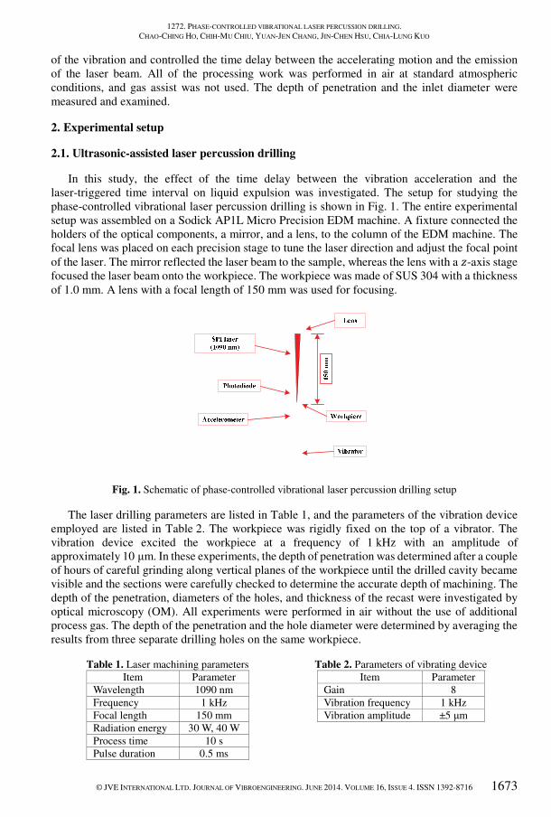
phase-controlled vibrational laser percussion drilling is shown in Fig. 1. The entire experimental
setup was assembled on a Sodick AP1L Micro Precision EDM machine. A fixture connected the
holders of the optical components, a mirror, and a lens, to the column of the EDM machine. The
focal lens was placed on each precision stage to tune the laser direction and adjust the focal point
of the laser. The mirror reflected the laser beam to the sample, whereas the lens with a �-axis stage
focused the laser beam onto the workpiece. The workpiece was made of SUS 304 with a thickness
of 1.0 mm. A lens with a focal length of 150 mm was used for focusing.
Fig. 1. Schematic of phase-controlled vibrational laser percussion drilling setup
The laser drilling parameters are listed in Table 1, and the parameters of the vibration device
employed are listed in Table 2. The workpiece was rigidly fixed on the top of a vibrator. The
vibration device excited the workpiece at a frequency of 1 kHz with an amplitude of
approximately 10 μm. In these experiments, the depth of penetration was determined after a couple
of hours of careful grinding along vertical planes of the workpiece until the drilled cavity became
visible and the sections were carefully checked to determine the accurate depth of machining. The
depth of the penetration, diameters of the holes, and thickness of the recast were investigated by
optical microscopy (OM). All experiments were performed in air without the use of additional
process gas. The depth of the penetration and the hole diameter were determined by averaging the
results from three separate drilling holes on the same workpiece.
Table 1. Laser machining parameters
Item Parameter
Wavelength 1090 nm
Frequency 1 kHz
Focal length 150 mm
Radiation energy 30 W, 40 W
Process time 10 s
Pulse duration 0.5 ms
Table 2. Parameters of vibrating device
Item Parameter
Gain 8
Vibration frequency 1 kHz
Vibration amplitude ±5 μm

1272. PHASE-CONTROLLED VIBRATIONAL LASER PERCUSSION DRILLING.
CHAO-CHING HO, CHIH-MU CHIU, YUAN-JEN CHANG, JIN-CHEN HSU, CHIA-LUNG KUO
1674 © JVE INTERNATIONAL LTD. JOURNAL OF VIBROENGINEERING. JUNE 2014. VOLUME 16, ISSUE 4. ISSN 1392-8716
2.2. Synchronization
The vibration of the workpiece and the emission of the laser beam were synchronized to
accelerate the workpiece at the time of drilling. For synchronization, the laser was operated in the
external trigger mode. The time delay between the vibration acceleration and the duty of the
emission of the laser beam was precisely synchronized by a pulse generator. To verify this
synchronization, a photodiode (Hamamatsu S1223 Si PIN photodiode) was positioned on the front
side of the workpiece to acquire the refraction of laser radiation after the emission of the laser
beam. An accelerometer (Brüel and Kjær Type 4507) was mounted on the workpiece, as shown
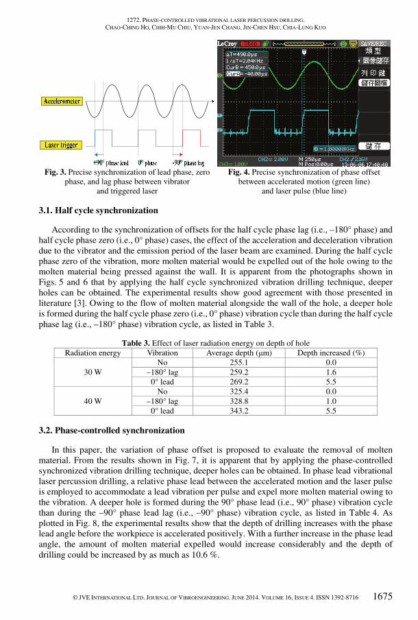
in Fig. 2, to measure vibration coaxial to the laser beam. As shown in Fig. 3, the zero phase
synchronization (i.e., 0°) was defined when the workpiece started to accelerate positively and the
laser was triggered. The lead phase synchronization was defined when the laser was triggered
(e.g., +60°) before the workpiece was accelerated positively. The lag phase synchronization was
defined when the laser was triggered (e.g., –60°) after the workpiece was accelerated positively.
As depicted in Fig. 4, the phase offset between the accelerated motion and the laser pulse was
synchronous with high accuracy. The output signal was measured by a digital oscilloscope
(Lecroy WaveAce 234).
Fig. 2. Installation of photodiode and accelerometer to verify synchronization
between vibration of workpiece and emission of laser beam
3. Results and discussion
The expulsion of the liquid in a laser-drilled hole can be improved by the vibration; that is,
molten material at the bottom of the drilling channel can be made to flow from the center toward
the sidewall of the drilled hole so that the material is eventually expelled out of the cavity entrances.
Two types of synchronization, i.e., half cycle synchronization and phase-controlled
synchronization, were conducted to verify the improvement as well as to compare the two control
strategies.
1272. PHASE-CONTROLLED VIBRATIONAL LASER PERCUSSION DRILLING.
CHAO-CHING HO, CHIH-MU CHIU, YUAN-JEN CHANG, JIN-CHEN HSU, CHIA-LUNG KUO
© JVE INTERNATIONAL LTD. JOURNAL OF VIBROENGINEERING. JUNE 2014. VOLUME 16, ISSUE 4. ISSN 1392-8716 1675
Fig. 3. Precise synchronization of lead phase, zero
phase, and lag phase between vibrator
and triggered laser
Fig. 4. Precise synchronization of phase offset
between accelerated motion (green line)
and laser pulse (blue line)
3.1. Half cycle synchronization
According to the synchronization of offsets for the half cycle phase lag (i.e., –180° phase) and
half cycle phase zero (i.e., 0° phase) cases, the effect of the acceleration and deceleration vibration
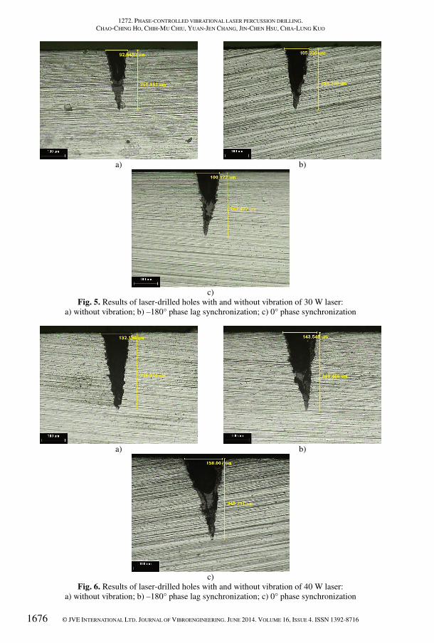
due to the vibrator and the emission period of the laser beam are examined. During the half cycle
phase zero of the vibration, more molten material would be expelled out of the hole owing to the
molten material being pressed against the wall. It is apparent from the photographs shown in
Figs. 5 and 6 that by applying the half cycle synchronized vibration drilling technique, deeper
holes can be obtained. The experimental results show good agreement with those presented in
literature [3]. Owing to the flow of molten material alongside the wall of the hole, a deeper hole
is formed during the half cycle phase zero (i.e., 0° phase) vibration cycle than during the half cycle
phase lag (i.e., –180° phase) vibration cycle, as listed in Table 3.
Table 3. Effect of laser radiation energy on depth of hole
Radiation energy Vibration Average depth (μm) Depth increased (%)
30 W
No 255.1 0.0
–180° lag 259.2 1.6
0° lead 269.2 5.5
40 W
No 325.4 0.0
–180° lag 328.8 1.0
0° lead 343.2 5.5
3.2. Phase-controlled synchronization
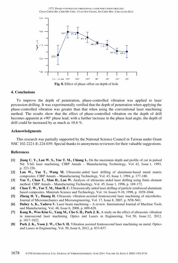
In this paper, the variation of phase offset is proposed to evaluate the removal of molten
material. From the results shown in Fig. 7, it is apparent that by applying the phase-controlled
synchronized vibration drilling technique, deeper holes can be obtained. In phase lead vibrational
laser percussion drilling, a relative phase lead between the accelerated motion and the laser pulse
is employed to accommodate a lead vibration per pulse and expel more molten material owing to
the vibration. A deeper hole is formed during the 90° phase lead (i.e., 90° phase) vibration cycle
than during the –90° phase lead lag (i.e., –90° phase) vibration cycle, as listed in Table 4. As
plotted in Fig. 8, the experimental results show that the depth of drilling increases with the phase
lead angle before the workpiece is accelerated positively. With a further increase in the phase lead
angle, the amount of molten material expelled would increase considerably and the depth of
drilling could be increased by as much as 10.6 %.
1272. PHASE-CONTROLLED VIBRATIONAL LASER PERCUSSION DRILLING.
CHAO-CHING HO, CHIH-MU CHIU, YUAN-JEN CHANG, JIN-CHEN HSU, CHIA-LUNG KUO
1676 © JVE INTERNATIONAL LTD. JOURNAL OF VIBROENGINEERING. JUNE 2014. VOLUME 16, ISSUE 4. ISSN 1392-8716
a)
b)
c)
Fig. 5. Results of laser-drilled holes with and without vibration of 30 W laser:
a) without vibration; b) –180° phase lag synchronization; c) 0° phase synchronization
a)
b)
c)
Fig. 6. Results of laser-drilled holes with and without vibration of 40 W laser:
a) without vibration; b) –180° phase lag synchronization; c) 0° phase synchronization

1272. PHASE-CONTROLLED VIBRATIONAL LASER PERCUSSION DRILLING.
CHAO-CHING HO, CHIH-MU CHIU, YUAN-JEN CHANG, JIN-CHEN HSU, CHIA-LUNG KUO
© JVE INTERNATIONAL LTD. JOURNAL OF VIBROENGINEERING. JUNE 2014. VOLUME 16, ISSUE 4. ISSN 1392-8716 1677
a)
b)
c)
d)
e)
f)
Fig. 7. Results of laser-drilled holes with and without vibration of 40 W laser:
a) +90° phase lead vibration; b) +60° phase lead vibration; c) +30° phase lead vibration;
d) 0° phase vibration; e) –60° phase lag vibration; f) –90° phase lag vibration
Table 4. Effect of phase offset on depth of hole
Phase Average depth (μm) Depth increased (%)
No 325.3 0
+90° 359.7 10.6
+60° 358.4 10.2
+30° 351.4 8.0
0° 345.3 6.1
–60° 331.2 2.0
–90° 330.5 2.0
1272. PHASE-CONTROLLED VIBRATIONAL LASER PERCUSSION DRILLING.
CHAO-CHING HO, CHIH-MU CHIU, YUAN-JEN CHANG, JIN-CHEN HSU, CHIA-LUNG KUO
1678 © JVE INTERNATIONAL LTD. JOURNAL OF VIBROENGINEERING. JUNE 2014. VOLUME 16, ISSUE 4. ISSN 1392-8716
Fig. 8. Effect of phase offset on depth of hole
4. Conclusions
To improve the depth of penetration, phase-controlled vibration was applied to laser
percussion drilling. It was experimentally verified that the depth of penetration when applying the
phase-controlled vibration was greater than that when using the conventional laser machining
method. The results show that the effect of phase-controlled vibration on the depth of drill
becomes apparent at +90° phase lead; with a further increase in the phase lead angle, the depth of
drill could be increased by as much as 10.6 %.
Acknowledgments
This research was partially supported by the National Science Council in Taiwan under Grant
NSC 102-2221-E-224-039. Special thanks to anonymous reviewers for their valuable suggestions.
References
[1] Jiang C. Y., Lau W. S., Yue T. M., Chiang L. On the maximum depth and profile of cut in pulsed
Nd: YAG laser machining. CIRP Annals – Manufacturing Technology, Vol. 42, Issue 1, 1993,
p. 223-226.
[2] Lau W., Yue T., Wang M. Ultrasonic-aided laser drilling of aluminum-based metal matrix
composites. CIRP Annals – Manufacturing Technology, Vol. 43, Issue 1, 1994, p. 177-180.
[3] Yue T., Chan T., Man H., Lau W. Analysis of ultrasonic-aided laser drilling using finite element
method. CIRP Annals – Manufacturing Technology, Vol. 45, Issue 1, 1996, p. 169-172.
[4] Chan T. W., Yue T. M., Man H. C. Ultrasonically aided laser drilling of particle reinforced aluminum
based composites. Materials Science and Technology, Vol. 14, Issues 9-10, 1998, p. 1039-1044.
[5] Zheng H. Y., Huang H. Ultrasonic vibration-assisted femtosecond laser machining of microholes.
Journal of Micromechanics and Microengineering, Vol. 17, Issue 8, 2007, p. N58-N61.
[6] Dubey A. K., Yadava V. Laser beam machining – A review. International Journal of Machine Tools
and Manufacturing, Vol. 48, Issue 6, 2008, p. 609-628.
[7] Kang B., Woo Kim G., Yang M., Cho S. H., Park J. K. A study on the effect of ultrasonic vibration
in nanosecond laser machining. Optics and Lasers in Engineering, Vol. 50, Issue 12, 2012,
p. 1817-1822.
[8] Park J. K., Yoon J. W., Cho S. H. Vibration assisted femtosecond laser machining on metal. Optics
and Lasers in Engineering, Vol. 50, Issue 6, 2012, p. 833-837.