Embed Size (px)
Citation preview
1255
Related InformationFIBERSENSORS
LASERSENSORS
PHOTOELECTRICSENSORS
MICROPHOTOELECTRIC
SENSORS
AREASENSORS
LIGHTCURTAINS
PRESSURE / FLOW
SENSORSINDUCTIVEPROXIMITY
SENSORS
PARTICULARUSE SENSORS
SENSOROPTIONS
SIMPLEWIRE-SAVING
UNITS
WIRE-SAVING SYSTEMS
MEASUREMENTSENSORS
STATIC CONTROLDEVICES
ENDOSCOPE
LASERMARKERS
PLC /TERMINALS
HUMAN MACHINE INTERFACES
ENERGY CONSUMPTION VISUALIZATION COMPONENTS
FA COMPONENTS
MACHINE VISION SYSTEMS
UV CURING SYSTEMS
Timers
Time Switches
Counters
Hour Meters
Options
Limit Switches
Fan Motors
Temperature Controllers
A-TB72/72Q
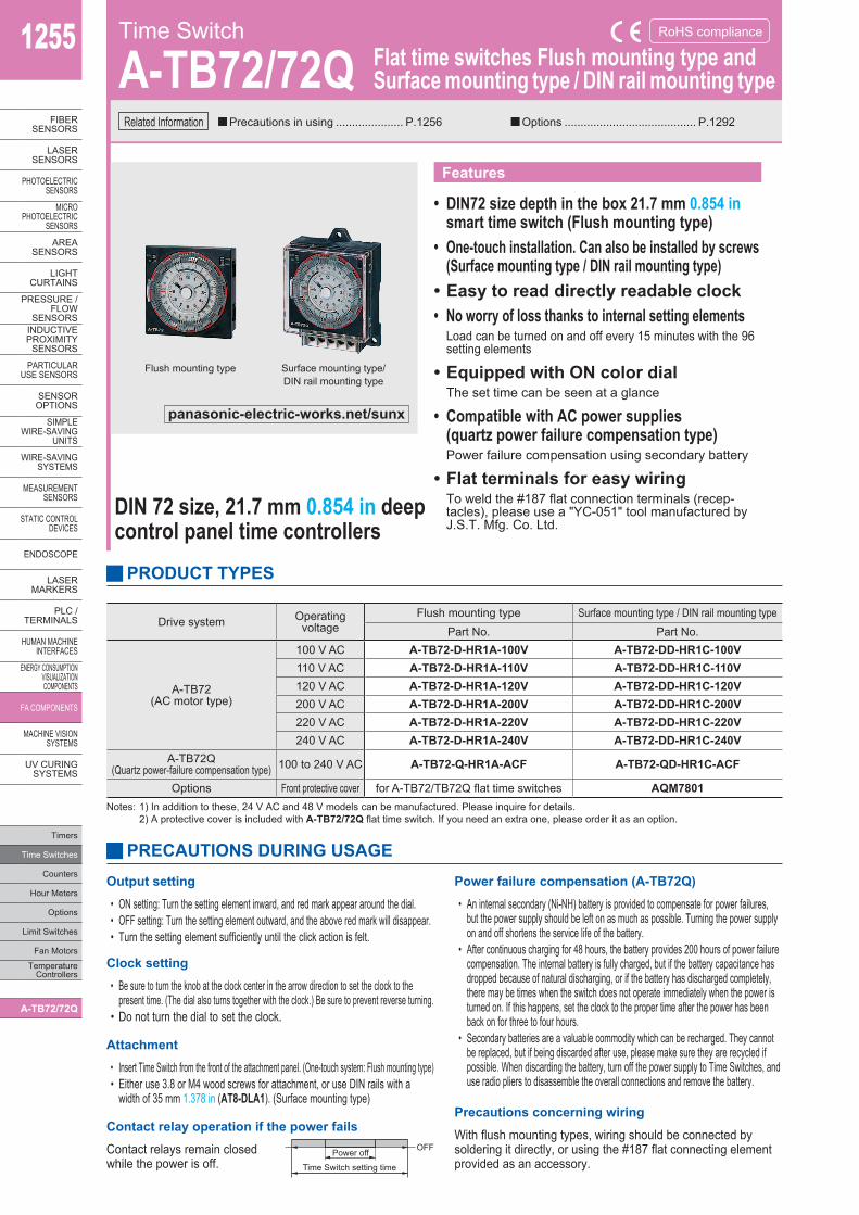
Flush mounting type Surface mounting type/DIN rail mounting type
Time Switch
A-TB72/72Q Flat time switches Flush mounting type andSurface mounting type / DIN rail mounting type
■Precautions in using ..................... P.1256 ■Options ......................................... P.1292
RoHS compliance
Features
• DIN72 size depth in the box 21.7 mm 0.854 in smart time switch (Flush mounting type)
• One-touch installation. Can also be installed by screws (Surface mounting type / DIN rail mounting type)
•Easy to read directly readable clock• No worry of loss thanks to internal setting elements
Load can be turned on and off every 15 minutes with the 96 setting elements
•Equipped with ON color dial The set time can be seen at a glance
• Compatible with AC power supplies (quartz power failure compensation type) Power failure compensation using secondary battery
•Flat terminals for easy wiring To weld the #187 flat connection terminals (recep-tacles), please use a "YC-051" tool manufactured by J.S.T. Mfg. Co. Ltd.
PRODUCT TYPES
PRECAUTIONS DURING USAGE
Notes: 1) In addition to these, 24 V AC and 48 V models can be manufactured. Please inquire for details.2) A protective cover is included with A-TB72/72Q flat time switch. If you need an extra one, please order it as an option.
Drive system Operating voltage
Flush mounting type Surface mounting type / DIN rail mounting typePart No. Part No.
A-TB72(AC motor type)
100 V AC A-TB72-D-HR1A-100V A-TB72-DD-HR1C-100V110 V AC A-TB72-D-HR1A-110V A-TB72-DD-HR1C-110V120 V AC A-TB72-D-HR1A-120V A-TB72-DD-HR1C-120V200 V AC A-TB72-D-HR1A-200V A-TB72-DD-HR1C-200V220 V AC A-TB72-D-HR1A-220V A-TB72-DD-HR1C-220V240 V AC A-TB72-D-HR1A-240V A-TB72-DD-HR1C-240V
A-TB72Q(Quartz power-failure compensation type) 100 to 240 V AC A-TB72-Q-HR1A-ACF A-TB72-QD-HR1C-ACF
Options Front protective cover for A-TB72/TB72Q flat time switches AQM7801
Output setting
• ON setting: Turn the setting element inward, and red mark appear around the dial.• OFF setting: Turn the setting element outward, and the above red mark will disappear.• Turn the setting element sufficiently until the click action is felt.
Power failure compensation (A-TB72Q)
• An internal secondary (Ni-NH) battery is provided to compensate for power failures, but the power supply should be left on as much as possible. Turning the power supply on and off shortens the service life of the battery.
• After continuous charging for 48 hours, the battery provides 200 hours of power failure compensation. The internal battery is fully charged, but if the battery capacitance has dropped because of natural discharging, or if the battery has discharged completely, there may be times when the switch does not operate immediately when the power is turned on. If this happens, set the clock to the proper time after the power has been back on for three to four hours.
• Secondary batteries are a valuable commodity which can be recharged. They cannot be replaced, but if being discarded after use, please make sure they are recycled if possible. When discarding the battery, turn off the power supply to Time Switches, and use radio pliers to disassemble the overall connections and remove the battery.
Clock setting
• Be sure to turn the knob at the clock center in the arrow direction to set the clock to the present time. (The dial also turns together with the clock.) Be sure to prevent reverse turning.
• Do not turn the dial to set the clock.
Attachment
• Insert Time Switch from the front of the attachment panel. (One-touch system: Flush mounting type)• Either use 3.8 or M4 wood screws for attachment, or use DIN rails with a
width of 35 mm 1.378 in (AT8-DLA1). (Surface mounting type)
Contact relay operation if the power fails
Contact relays remain closed while the power is off.
Precautions concerning wiring
With flush mounting types, wiring should be connected by soldering it directly, or using the #187 flat connecting element provided as an accessory.
Power off OFF
Time Switch setting time
DIN 72 size, 21.7 mm 0.854 in deep control panel time controllers
panasonic-electric-works.net/sunx
1256
FIBERSENSORS
LASERSENSORS
PHOTO-ELECTRICSENSORSMICROPHOTO-ELECTRICSENSORS
AREASENSORS
LIGHTCURTAINS
PRESSURE / FLOWSENSORS
INDUCTIVEPROXIMITYSENSORS
PARTICULARUSE SENSORS
SENSOROPTIONS
SIMPLEWIRE-SAVINGUNITS
WIRE-SAVING SYSTEMS
MEASURE-MENTSENSORS
STATIC CONTROLDEVICES
ENDOSCOPE
LASERMARKERS
PLC /TERMINALS
HUMAN MACHINE INTERFACESENERGY CONSUMPTION VISUALIZATION COMPONENTS
FA COMPONENTS
MACHINE VISION SYSTEMS
UV CURING SYSTEMS
Timers
Time Switches
Counters
Hour Meters
Options
Limit SwitchesFan MotorsTemperature Controllers
A-TB72/72Q
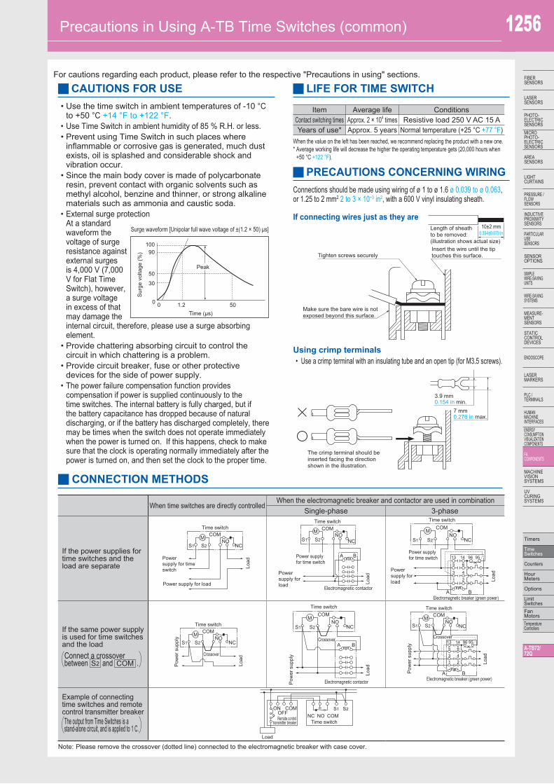
Tighten screws securelyInsert the wire until the tiptouches this surface.
10±2 mm0.394±0.079 in
Length of sheathto be removed:(illustration shows actual size)
Make sure the bare wire is notexposed beyond this surface.
• Use the time switch in ambient temperatures of -10 °C to +50 °C +14 °F to +122 °F.
• Use Time Switch in ambient humidity of 85 % R.H. or less.• Prevent using Time Switch in such places where
inflammable or corrosive gas is generated, much dust exists, oil is splashed and considerable shock and vibration occur.
• Since the main body cover is made of polycarbonate resin, prevent contact with organic solvents such as methyl alcohol, benzine and thinner, or strong alkaline materials such as ammonia and caustic soda.
• External surge protection At a standard waveform the voltage of surge resistance against external surges is 4,000 V (7,000 V for Flat Time Switch), however, a surge voltage in excess of that may damage the internal circuit, therefore, please use a surge absorbing element.
• Provide chattering absorbing circuit to control the circuit in which chattering is a problem.
• Provide circuit breaker, fuse or other protective devices for the side of power supply.
• The power failure compensation function provides compensation if power is supplied continuously to the time switches. The internal battery is fully charged, but if the battery capacitance has dropped because of natural discharging, or if the battery has discharged completely, there may be times when the switch does not operate immediately when the power is turned on. If this happens, check to make sure that the clock is operating normally immediately after the power is turned on, and then set the clock to the proper time.
When the value on the left has been reached, we recommend replacing the product with a new one.* Average working life will decrease the higher the operating temperature gets (20,000 hours when
+50 °C +122 °F).
Connections should be made using wiring of ø 1 to ø 1.6 ø 0.039 to ø 0.063, or 1.25 to 2 mm2 2 to 3 × 10⁻³ in2, with a 600 V vinyl insulating sheath.
Note: Please remove the crossover (dotted line) connected to the electromagnetic breaker with case cover.
Precautions in Using A-TB Time Switches (common)
For cautions regarding each product, please refer to the respective "Precautions in using" sections.
CAUTIONS FOR USE LIFE FOR TIME SWITCH
PRECAUTIONS CONCERNING WIRING
Surge waveform [Unipolar full wave voltage of ±(1.2 × 50) μs]
10090
50
30
0 0 1.2Time (μs)
50
Peak
Sur
ge v
olta
ge (%
)
Item Average life ConditionsContact switching times Approx. 2 × 10⁴ times Resistive load 250 V AC 15 AYears of use* Approx. 5 years Normal temperature (+25 °C +77 °F)
CONNECTION METHODS
When time switches are directly controlledWhen the electromagnetic breaker and contactor are used in combination
Single-phase 3-phase
If the power supplies for time switches and the load are separate
If the same power supply is used for time switches and the load
Example of connecting time switches and remote control transmitter breaker
Connect a crossoverbetween S2 and COM .
The output from Time Switches is a stand-alone circuit, and is applied to 1 C.
MS2S1
Time switchCOM
NONC
Powersupply for timeswitch
Power supply for load
Load
MS2S1
Time switch
Crossover
COMNO
NC
Pow
er s
uppl
y
Load
Power supplyfor time switch
MS2S1
Electromagnetic contactor
Time switchCOM
BA
NONC
Powersupply forload Lo
ad
S2S1
Pow
er s
uppl
y
Load
Crossover
M
Electromagnetic contactor
Time switchCOM
BA
NONC
95961413
65
43
21
Power supplyfor time switch
M
S2S1
Electromagnetic breaker (green power)
Time switchCOM
BA
NONC
Powersupply forload Lo
ad
S2S1
Pow
er s
uppl
y
Load
9596141365
4321
M
Electromagnetic breaker (green power)
Time switchCOM
BA
NONC
Crossover
S2S1
Remote controltransmitter breaker
OFF
Time switchNC NO COM
COMON
Load
The crimp terminal should beinserted facing the directionshown in the illustration.
3.9 mm0.154 in min.
7 mm0.276 in max.
If connecting wires just as they are
Using crimp terminals• Use a crimp terminal with an insulating tube and an open tip (for M3.5 screws).