Embed Size (px)
Citation preview
Page 1 of 27
GRP BOAT BUILDING INSTRUCTIONS – 2006 TABLE OF CONTENTS
1.0 COPYRIGHT 4
2.0 PLAN SET and MEASUREMENT 4
3.0 MATERIALS FOR HULL 4 3.1 Patterns 4 3.2 Foam Panels 4 3.3 Resin 4 3.4 Fibreglass Matt 4 3.5 Timber 4 3.6 Tools 4 3.7 Consumables 5
4.0 MOULD 5 4.1 Ownership and License to Use Mould 5
5.0 BUILDING THE HULL 5 5.1 Requirements 5
5.1.1 Location 5 5.1.2 Deck Layout 6 5.1.3 Safe Working 6
5.2 Hull Foam Panels 6 5.2.1 Trace patterns 6
5.3 Preparing the Mould 7 5.3.1.Patch & fill 7 5.3.2 Fit Transom & Centrecase Insert 7 5.3.3 Check Foam Panel fit 7 5.3.4 Waxing 8 5.3.5 Seal Centrecase Insert 8 5.3.6 Undercoat Mould 9 5.3.7 Apply Fillets to Chine, Front of Bow and Transom 9
5.4 Glass Outer Layer, Glue Foam & vacuum bag hull 9 5.4.1 Cut Out Fibreglass Matt 10 5.4.2 Lay-up Outer Layer 10 5.4.3 Glue Hull Foam Pieces in Position 11 5.4.4 Vacuum Bagging 11
5.5 Inner layer 13 5.5.1 Insert Timber Reinforcing Panels 13 5.5.2 Fill Gaps between Foam Pieces 13 5.5.3 Cut Matt Pieces for Inner Layer 13 5.5.4 Lay-up Inner Layer 14
5.6 Remove Hull from Mould 15
6.0 INTERNAL BULKHEADS & SUPPORTS IN HULL 15 6.1 Lay-Up Sheets for Internal Supports 15 6.2 Insert Timber Reinforcing 16 6.3 Fit Main Bulkhead 16
VICTORIAN DIVISION INC. 125 ASSOCIATION

125 GRP Boat Building Instructions December 2006
GRP BOAT BUILDING INSTRUCTIONS - 2006 Draft Version 1 2.doc Page 2 of 27
6.4 Fit Forward Bulkhead & Web 17 6.5 Fit Seat Sides & Baffles 17 6.6 Glue Bulkheads, Web, Baffles and Seat sides 18 6.7 Remove Hull from Mould 18 6.8 Cleanup of Mould 18
7.0 CENTREBOARD CASE & THWART 18 7.1 Prepare Moulds 18 7.2 Lay-up Inner Layer & Foam Panels 18
7.2.1 Centreboard case 18 7.2.2 Thwart 18
7.3 Remove Centrecase insert from Mould 19 7.4 Install Centrecase 19 7.5 Install Thwart 19
8.0 SANDING INTERIOR OF HULL 19 8.1 Clean up fillets 19 8.2 Floor & sides 20 8.3 Final fairing and filling 20
9.0 FITTING DECK & SEAT TOPS 20 9.1 Seat & Deck Supports along Hull 20 9.2 Trim seats & deck 20 9.3 Glue Seat tops & Foredeck 21 9.4 Sanding taped joints 21
10.0 BOW COVER 21
11.0 GLASSING GUNWALES & EXPOSED JOINTS 21 11.1 Glassing Gunwales 21 11.2 Glassing Exposed Joints 22
12.0 CUT OUTS 22 12.1 Inspection Hatches 22 12.2 Hand holes in transom 22 12.3 Scuppers 22 12.4 Venturi Bailers 22
13.0 SANDING EXTERIOR OF HULL 23
14.0 PAINTING 23
15.0 FITOUT & RIGGING HULL 23 15.1 Fittings 23 14.2 Rigging 23
16.0 BOOM, MAST & SPINNAKER POLE 24 16.1 Mast 24 16.2 Boom 24 16.3 Spinnaker Pole 24
17.0 CENTREBOARD, RUDDER 24
18.0 SAILS 24
17.0 BEACH TROLLEY 24
18.0 TRAILER 24
19.0 COST ESTIMATE 24

125 GRP Boat Building Instructions December 2006
GRP BOAT BUILDING INSTRUCTIONS - 2006 Draft Version 1 2.doc Page 3 of 27
APPENDIX A 26 Reference Documents 26
APPENDIX B 26 Approx Build timeframe 26
APPENDIX C – LIST OF SUPPLIERS 27
125 GRP Boat Building Instructions December 2006
GRP BOAT BUILDING INSTRUCTIONS - 2006 Draft Version 1 2.doc Page 4 of 27
1.0 COPYRIGHT The 125 Class Yacht is copyright by the 125 Association. .Reproduction of patterns, sail specifications, drawings or any other matter issued by the Association, with out permission is forbidden. The plans, drawings, instructions, and patterns are sold to you on your agreement to abide by this copyright.
2.0 PLAN SET and MEASUREMENT To qualify as a 125 class yacht, your boat must comply with all the Measurement Rules (The latest copy of the Measurement Rules can be obtained on the 125 Association website www.125assoc.com) A Sail number is allocated by the National Measurer and a fee of $40 is payable to the Victorian Association for the Sail number and initial Measurement which is required before you can race your 125. To assist you with building, these instructions remind you when to check measure. On completion, you must arrange for you boat to be measured by the State Measurer. Please refer to the Association website for contact details.
3.0 MATERIALS FOR HULL
3.1 Patterns Build patterns for foam panels (Supplied with mould)
3.2 Foam Panels X Sheets of 8mm foam panels (1220 mm x 2400 mm) Y Sheets of 5 mm foam (1220 mm x 2400 mm)
3.3 Resin X Litres of resin ( litre drum) Y Litres of hardener Z bags of q cells ( kg bag)
3.4 Fibreglass Matt Metres of xx gm/sq m fibreglass matt Peel ply Shade cloth
3.5 Timber Marine ply sheets for timber inserts
3.6 Tools Stanley Knife Jig saw Foam Paint rollers
125 GRP Boat Building Instructions December 2006
GRP BOAT BUILDING INSTRUCTIONS - 2006 Draft Version 1 2.doc Page 5 of 27
Paint brushes (cheap ones from Bunning’s as they can be used once only & thrown away)
Fibreglass rollers 2 Litre Milk Containers Plastic containers or tins for mixing resin Scissors Tape measure Hammer Chisel Shifting spanner Screwdrivers Orbital Sander with vacuum collection, discs (80, 120)
Vacuum Cleaner
3.7 Consumables Disposable gloves & disposable overalls for fibreglassing Dust masks Clean Rags, Mineral turps for cleaning tools Sandpaper – 80, 120 Wet & dry -
Tacky Tape (for vacuum bagging) Masking tape
4.0 MOULD
4.1 Ownership and License to Use Mould The mould is owned by a Co-Operative of Victorian 125 sailors. A fee is payable to the co operative to cover expenses in storing and maintaining the mould. These instructions are based on construction of a moulded hull and panels cut and glued for the bulkheads, seat sides, tops, and foredeck. There is a deck mould that can be used, but this is not detailed in these instructions.
5.0 BUILDING THE HULL
5.1 Requirements
5.1.1 Location You will need a secure, dust free environment in which to build such as a garage. The mould can be placed on a bed frame mounted with castors to bring it to an easy working height, and also enable it to be moved around as required.
125 GRP Boat Building Instructions December 2006
GRP BOAT BUILDING INSTRUCTIONS - 2006 Draft Version 1 2.doc Page 6 of 27
5.1.2 Deck Layout The first task is to establish the deck layout of the fittings. These are placed largely based on personal choice, Measurement Rules permitting. You are advised to inspect other boats, talk to their owners, and decide where fittings are best placed for your needs. Marine ply timber reinforcement pads need to be placed into the hull, tank sides, bulkheads, deck and seats at locations where fittings are to be fixed, so it is important that before commencing the build you have established where these pads will be located.
5.1.3 Safe Working Please ensure that you observe all safety precautions while working including the use of dust masks, gloves etc. Adequate ventilation is also important when working with resins.
5.2 Hull Foam Panels
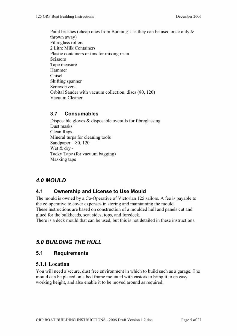
5.2.1 Trace patterns Using the pattern layout shown, trace the hull patterns using a felt pen onto the foam sheets. No. 1. Bottom Aft - 2 required (8mm sheet) No. 2. Bottom Front – 2 required (8 mm sheet) No. 2A. Bow - 2 required (8 mm sheet) No. 3 Side Aft – 2 required (5 mm sheet) No. 4. Side Front – 2 required (5 mm sheet No. 5. Transom inserts – 4 required (8 mm sheet) No. 9. Centrecase - 2 required (8 mm sheet) Label each piece with its name and which is the aft end.
AFT AFTNo.9 No. 9 No. 2Centre Centre BottomCase Case Front
No 1 No 1Bottom Bottom
Aft AftTransom No. 2Inserts (4 off) Bottom
FrontNo. 2A
AFT Bow AFT
SHEET 1 (8 mm) SHEET 2 (8 mm)
125 GRP Boat Building Instructions December 2006
GRP BOAT BUILDING INSTRUCTIONS - 2006 Draft Version 1 2.doc Page 7 of 27
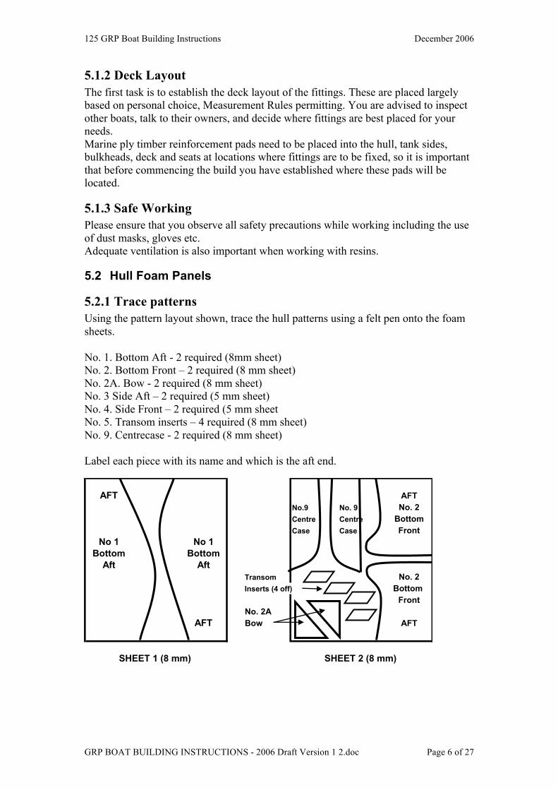
AFT No 4SideFront
No 3 No 3Side SideAft Aft
No 4Side AFTFront
SHEET 3 (5 mm) Cut each piece of foam out using a Stanley knife. (photo of cutting) To assist in getting a good key & bond between fibreglass matt & the foam, punch nail holes in both sides of the foam at regular intervals. – it is a good idea to make up a nail board to make this task easier. (photo of nail board)
5.3 Preparing the Mould
5.3.1.Patch & fill The gunwales should be patched and filled with plastibond, then sanded smooth. Generally, the area around the bow and transom needs the most attention.
5.3.2 Fit Transom & Centrecase Insert Bolt the Transom section onto the mould using the bolts supplied. Bolt the centrecase insert into the bottom of the mould. There are three bolts, the middle bolt goes right through the mould and is bolted with a washer & nit underneath. The forward and aft bolts thread directly into the mould.
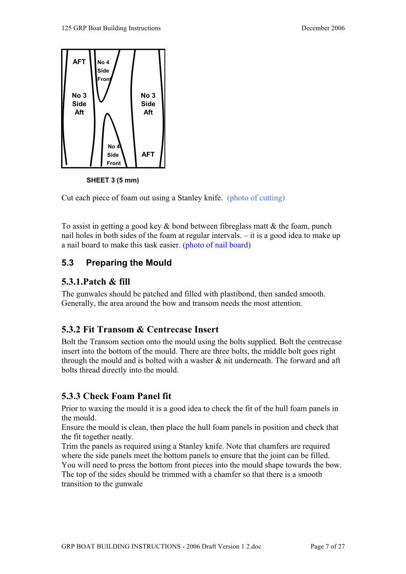
5.3.3 Check Foam Panel fit Prior to waxing the mould it is a good idea to check the fit of the hull foam panels in the mould. Ensure the mould is clean, then place the hull foam panels in position and check that the fit together neatly. Trim the panels as required using a Stanley knife. Note that chamfers are required where the side panels meet the bottom panels to ensure that the joint can be filled. You will need to press the bottom front pieces into the mould shape towards the bow. The top of the sides should be trimmed with a chamfer so that there is a smooth transition to the gunwale
125 GRP Boat Building Instructions December 2006
GRP BOAT BUILDING INSTRUCTIONS - 2006 Draft Version 1 2.doc Page 8 of 27
Smooth off foam toeven line at gunwale
Foam PanelsChamfer foam at join laid in mould
Mould
The timber transom reinforcing piece should also be checked for fit at this stage Label each piece Port or Starboard once trimmed.
5.3.4 Waxing The mould must be waxed with a mould release wax. The recommended product is NU-CEARAWAX made by Huntsman Chemicals. (See ………..for the MSDS and Instructions for use from the manufacturer) Vacuum the inside of the mould to remove and dust and foam particles Seven coats of wax are required over the mould, gunwales, transom and centrecase insert. Follow the manufacturer’s instructions. It takes about 45 minutes for one person to wax and polish each coat. Cover the mould with old sheets between coats to prevent dust getting onto the waxed surface The mould should exhibit a smooth glassy appearance as shown in the photo below (insert photo) Do not skimp on the waxing, a mirror finish is required for a smooth hull and to enable release of the hull from the mould with out damaging the hull or more importantly the mould.
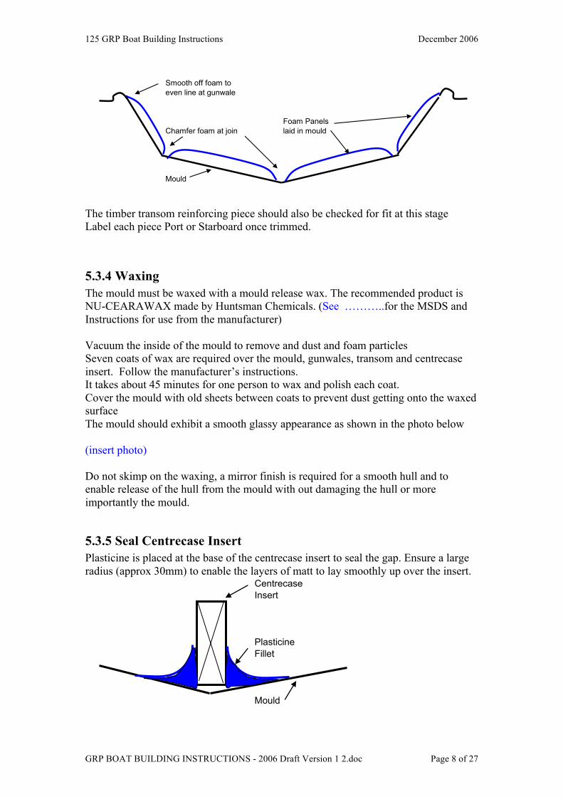
5.3.5 Seal Centrecase Insert Plasticine is placed at the base of the centrecase insert to seal the gap. Ensure a large radius (approx 30mm) to enable the layers of matt to lay smoothly up over the insert.
Centrecase Insert
PlasticineFillet
Mould
125 GRP Boat Building Instructions December 2006
GRP BOAT BUILDING INSTRUCTIONS - 2006 Draft Version 1 2.doc Page 9 of 27
5.3.6 Undercoat Mould Once the waxing is complete, undercoat is sprayed into the mould. Place masking tape over the flat extension of the gunwales so it is not painted. Use International Paints xyz ………….. Paint the gunwales with a brush.
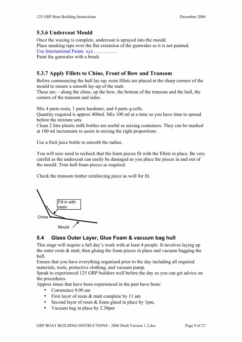
5.3.7 Apply Fillets to Chine, Front of Bow and Transom Before commencing the hull lay-up, resin fillets are placed at the sharp corners of the mould to ensure a smooth lay-up of the matt. These are: - along the chine, up the bow, the bottom of the transom and the hull, the corners of the transom and sides. Mix 4 parts resin, 1 parts hardener, and 4 parts q-cells. Quantity required is approx 400ml. Mix 100 ml at a time so you have time to spread before the mixture sets. Clean 2 litre plastic milk bottles are useful as mixing containers. They can be marked at 100 ml increments to assist in mixing the right proportions. Use a fruit juice bottle to smooth the radius. You will now need to recheck that the foam pieces fit with the fillets in place. Be very careful as the undercoat can easily be damaged as you place the pieces in and out of the mould. Trim hull foam pieces as required. Check the transom timber reinforcing piece as well for fit.
Fill in with resin
Chine
Mould
5.4 Glass Outer Layer, Glue Foam & vacuum bag hull This stage will require a full day’s work with at least 4 people. It involves laying up the outer resin & matt, then gluing the foam pieces in place and vacuum bagging the hull. Ensure that you have everything organised prior to the day including all required materials, tools, protective clothing, and vacuum pump. Speak to experienced 125 GRP builders well before the day so you can get advice on the procedures. Approx times that have been experienced in the past have been:
• Commence 9.00 am • First layer of resin & matt complete by 11 am • Second layer of resin & foam glued in place by 1pm, • Vacuum bag in place by 2.30pm
125 GRP Boat Building Instructions December 2006
GRP BOAT BUILDING INSTRUCTIONS - 2006 Draft Version 1 2.doc Page 10 of 27
Best method is to have one person designated as the resin mixer, one person coordinating the work and 2 people as the hands.
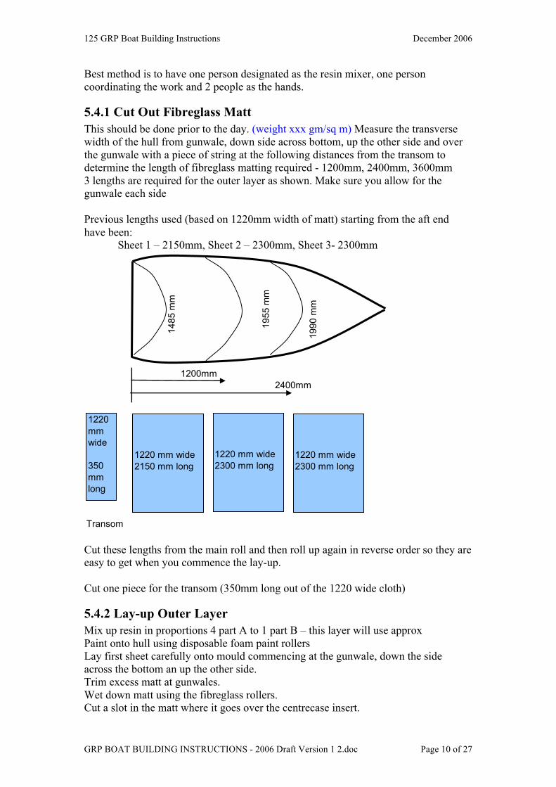
5.4.1 Cut Out Fibreglass Matt This should be done prior to the day. (weight xxx gm/sq m) Measure the transverse width of the hull from gunwale, down side across bottom, up the other side and over the gunwale with a piece of string at the following distances from the transom to determine the length of fibreglass matting required - 1200mm, 2400mm, 3600mm 3 lengths are required for the outer layer as shown. Make sure you allow for the gunwale each side Previous lengths used (based on 1220mm width of matt) starting from the aft end have been:
Sheet 1 – 2150mm, Sheet 2 – 2300mm, Sheet 3- 2300mm
1200mm2400mm
Transom
1990
mm
148
5 m
m
1
955
mm
1220 mm wide 2150 mm long
1220 mm wide 2300 mm long
1220 mm wide 2300 mm long
1220mm wide
350 mm long
Cut these lengths from the main roll and then roll up again in reverse order so they are easy to get when you commence the lay-up. Cut one piece for the transom (350mm long out of the 1220 wide cloth)
5.4.2 Lay-up Outer Layer Mix up resin in proportions 4 part A to 1 part B – this layer will use approx Paint onto hull using disposable foam paint rollers Lay first sheet carefully onto mould commencing at the gunwale, down the side across the bottom an up the other side. Trim excess matt at gunwales. Wet down matt using the fibreglass rollers. Cut a slot in the matt where it goes over the centrecase insert.
125 GRP Boat Building Instructions December 2006
GRP BOAT BUILDING INSTRUCTIONS - 2006 Draft Version 1 2.doc Page 11 of 27
Continue forward with sheets 2 & 3, overlapping each sheet to the blue line (approx 50 mm) There will be enough left over from the edges of Sheet 3 to do the last section at the bow. Place transom piece of matt & wet down. Ensure all air bubbles are removed and that the matt is fully wetted down. Make sure the gunwales are smooth with no protruding pieces of glass matt Wait for 45min till resin is tacky.
5.4.3 Glue Hull Foam Pieces in Position Mix up resin, hardener mixture in the following proportions: 4:1 This layer will use approx 2.75 to 3.0 litres of mixed resin. Mix in 500 ml batches as required. Starting with the Bottom Aft pieces (No 1) using a squeegee spread resin mixture all over the foam on the underside. Spread resin mixture over hull mould to cover the area of this piece of foam. Place the foam piece in position in the hull. Repeat for the other hull foam pieces in the following order:
Transom timber stiffener Bottom Aft (No 1)
Bottom Front (No 2) Sides Aft (No 3)
Side Front (No 4) Bow (No 2A) Transom inserts (No 5)
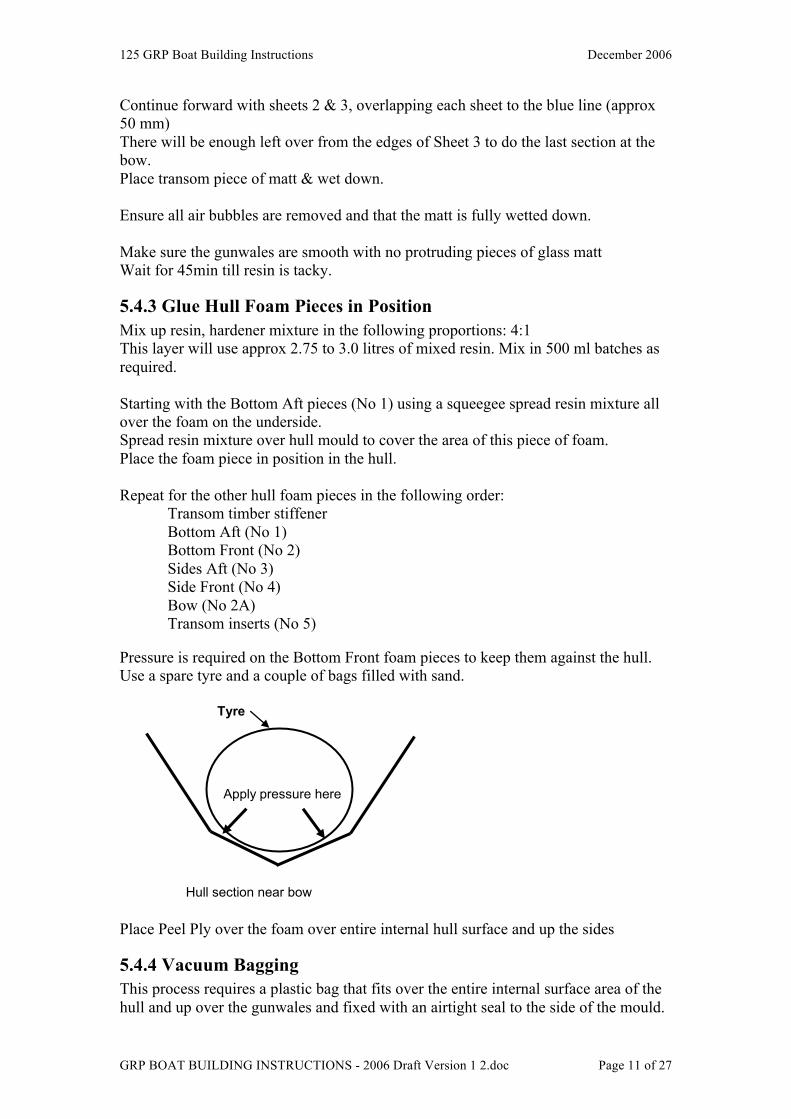
Pressure is required on the Bottom Front foam pieces to keep them against the hull. Use a spare tyre and a couple of bags filled with sand.
Tyre
Apply pressure here
Hull section near bow Place Peel Ply over the foam over entire internal hull surface and up the sides
5.4.4 Vacuum Bagging This process requires a plastic bag that fits over the entire internal surface area of the hull and up over the gunwales and fixed with an airtight seal to the side of the mould.
125 GRP Boat Building Instructions December 2006
GRP BOAT BUILDING INSTRUCTIONS - 2006 Draft Version 1 2.doc Page 12 of 27
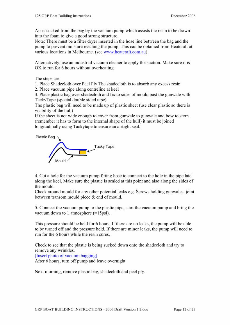
Air is sucked from the bag by the vacuum pump which assists the resin to be drawn into the foam to give a good strong structure. Note: There must be a filter dryer inserted in the hose line between the bag and the pump to prevent moisture reaching the pump. This can be obtained from Heatcraft at various locations in Melbourne. (see www.heatcraft.com.au) Alternatively, use an industrial vacuum cleaner to apply the suction. Make sure it is OK to run for 6 hours without overheating. The steps are: 1. Place Shadecloth over Peel Ply The shadecloth is to absorb any excess resin 2. Place vacuum pipe along centreline at keel 3. Place plastic bag over shadecloth and fix to sides of mould past the gunwale with TackyTape (special double sided tape) The plastic bag will need to be made up of plastic sheet (use clear plastic so there is visibility of the hull) If the sheet is not wide enough to cover from gunwale to gunwale and bow to stern (remember it has to form to the internal shape of the hull) it must be joined longitudinally using Tackytape to ensure an airtight seal. Plastic Bag
Tacky Tape
Mould
4. Cut a hole for the vacuum pump fitting hose to connect to the hole in the pipe laid along the keel. Make sure the plastic is sealed at this point and also along the sides of the mould. Check around mould for any other potential leaks e.g. Screws holding gunwales, joint between transom mould piece & end of mould. 5. Connect the vacuum pump to the plastic pipe, start the vacuum pump and bring the vacuum down to 1 atmosphere (=15psi). This pressure should be held for 6 hours. If there are no leaks, the pump will be able to be turned off and the pressure held. If there are minor leaks, the pump will need to run for the 6 hours while the resin cures. Check to see that the plastic is being sucked down onto the shadecloth and try to remove any wrinkles. (Insert photo of vacuum bagging) After 6 hours, turn off pump and leave overnight Next morning, remove plastic bag, shadecloth and peel ply.
125 GRP Boat Building Instructions December 2006
GRP BOAT BUILDING INSTRUCTIONS - 2006 Draft Version 1 2.doc Page 13 of 27
5.5 Inner layer
5.5.1 Insert Timber Reinforcing Panels From the deck layout, determine where fittings are required to be bolted through the hull. Marine ply timber inserts will be required at these points to avoid the foam being crushed when fittings are bolted through. Typical requirements are: Chainplates, Spinnaker barber hauler, spinnaker guy turning blocks at rear of gunwale and adjacent to thwart. Measure accurately the position of each of these blocks; mark out on foam with felt pen the score the line with a Stanley knife through the foam but not to the outer layer of matting. Using a chisel, remove all the foam, then mix up a resin mixture and glue the timber blocks in place. The timber should be scored on the glued side to enable a good key between glue and timber. Generally thickness of ply should be the same as the foam used in the side panels, except for chainplates where at least 18mm thickness by 100mm width should be used. The chainplate ply must extend from the gunwale to below the seat top (Refer Rule 2.12, Measurements 44, 45)
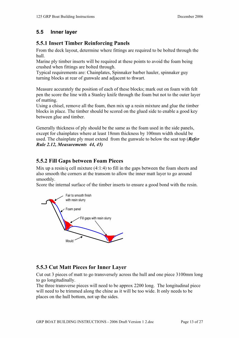
5.5.2 Fill Gaps between Foam Pieces Mix up a resin/q cell mixture (4:1:4) to fill in the gaps between the foam sheets and also smooth the corners at the transom to allow the inner matt layer to go around smoothly. Score the internal surface of the timber inserts to ensure a good bond with the resin.
Fair to smooth finish with resin slurry
Foam panel
Fill gaps with resin slurry
Mould
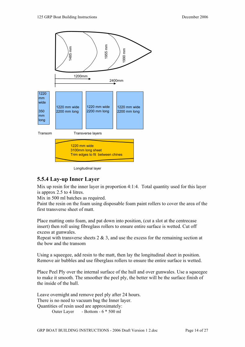
5.5.3 Cut Matt Pieces for Inner Layer Cut out 3 pieces of matt to go transversely across the hull and one piece 3100mm long to go longitudinally. The three transverse pieces will need to be approx 2200 long. The longitudinal piece will need to be trimmed along the chine as it will be too wide. It only needs to be places on the hull bottom, not up the sides.
125 GRP Boat Building Instructions December 2006
GRP BOAT BUILDING INSTRUCTIONS - 2006 Draft Version 1 2.doc Page 14 of 27
1200mm2400mm
Transom Transverse layers
Longitudinal layer
1990
mm
148
5 m
m
1
955
mm
1220 mm wide 2200 mm long
1220 mm wide 2200 mm long
1220 mm wide 2200 mm long
1220mm wide
350 mm long
1220 mm wide 3100mm long sheet Trim edges to fit between chines
5.5.4 Lay-up Inner Layer Mix up resin for the inner layer in proportion 4:1:4. Total quantity used for this layer is approx 2.5 to 4 litres. Mix in 500 ml batches as required. Paint the resin on the foam using disposable foam paint rollers to cover the area of the first transverse sheet of matt. Place matting onto foam, and pat down into position, (cut a slot at the centrecase insert) then roll using fibreglass rollers to ensure entire surface is wetted. Cut off excess at gunwales. Repeat with transverse sheets 2 & 3, and use the excess for the remaining section at the bow and the transom Using a squeegee, add resin to the matt, then lay the longitudinal sheet in position. Remove air bubbles and use fiberglass rollers to ensure the entire surface is wetted. Place Peel Ply over the internal surface of the hull and over gunwales. Use a squeegee to make it smooth. The smoother the peel ply, the better will be the surface finish of the inside of the hull. Leave overnight and remove peel ply after 24 hours. There is no need to vacuum bag the Inner layer. Quantities of resin used are approximately:
Outer Layer - Bottom - 6 * 500 ml
125 GRP Boat Building Instructions December 2006
GRP BOAT BUILDING INSTRUCTIONS - 2006 Draft Version 1 2.doc Page 15 of 27
- Foam - 7 * 500 ml - Q cell - 4 * 500 ml Inner Layer - 7 * 500 ml Longitudinal Sheet - 2 * 500 ml
5.6 Remove Hull from Mould After Inner layer has cured for a week, the hull needs to be released from the mould. Unbolt the transom section of the mould and the bolts holding the centrecase insert. Gently prise the gunwales off the mould using a putty spatula Elevate the aft section of the mould by about 600 mm and place on supports Using a rubber mallet, bang the external sides and underneath of the mould. Open the gap at the transom using a putty spatula. Gently insert wedges under the transom and under the gunwales to release the hull. Using the white plastic strip wedge and its extension, gently introduce it between the gap of hull and mould. Work across the hull and then deeper towards the bow Introduce water in between the hull and mould as this will help release the hull. Take your time and be careful not to damage either the hull or the mould surface. Once the hull has been released, protect the underneath by placing on a beach trolley while the internal surface of the mould is inspected. Clean up the mould and return the hull to the mould so it retains its shape while the internal bulkheads, tanks and baffles are fitted.
6.0 INTERNAL BULKHEADS & SUPPORTS IN HULL
6.1 Lay-Up Sheets for Internal Supports Fibreglass matt must be laid on both sides of the foam sheet to form a reinforced sandwich panel. The requirement is for:
One sheet of 1200mm wide, 2400 mm long and 8mm thick foam Two sheets of 1200mm wide, 2400 mm long, 5 mm thick foam
This provides the material for the internal bulkheads, (8 mm thick foam) tank sides, baffles , seat tops, foredeck & bow cover. (5mm thick foam) It is useful to have a table made up of a sheet of 1200 by 2400 MDF timber to use as a working surface. Cover with a plastic sheet. Cut out the required length of fibreglass matting from the roll Mix up a quantity of resin in the proportions 4:1 (4 parts resin, 1 part hardener) Apply to the foam panel using a squeegee, then lay the fibreglass matt over the sheet Use the squeegee to wet down the fibreglass matting and roll out with the fibreglass rollers. Place Peel Ply over the matting and smooth out. This will ensure a smooth finish on the panel.
125 GRP Boat Building Instructions December 2006
GRP BOAT BUILDING INSTRUCTIONS - 2006 Draft Version 1 2.doc Page 16 of 27
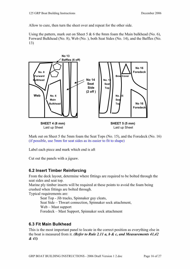
Allow to cure, then turn the sheet over and repeat for the other side. Using the pattern, mark out on Sheet 5 & 6 the 8mm foam the Main bulkhead (No. 6), Forward Bulkhead (No. 8), Web (No. ), both Seat Sides (No. 14), and the Baffles (No. 13)
No 13Baffles (6 off)
No 16No. 8 Foredeck
Forward Bow CoverBulkhead No 14 No. 15
Seat SeatSide Top
(2 off )Web No. 6 No. 15
Main SeatBulkhead Top No 16
Foredeck
Laid up Sheet Laid up SheetSHEET 4 (8 mm) SHEET 5 (5 mm)
Mark out on Sheet 5 the 5mm foam the Seat Tops (No. 15), and the Foredeck (No. 16) (if possible, use 5mm for seat sides as its easier to fit to shape) Label each piece and mark which end is aft Cut out the panels with a jigsaw.
6.2 Insert Timber Reinforcing From the deck layout, determine where fittings are required to be bolted through the seat sides and seat top. Marine ply timber inserts will be required at these points to avoid the foam being crushed when fittings are bolted through. Typical requirements are:
Seat Top - Jib tracks, Spinnaker guy cleats, Seat Side – Thwart connection, Spinnaker sock attachment, Web – Mast support Foredeck – Mast Support, Spinnaker sock attachment
6.3 Fit Main Bulkhead This is the most important panel to locate in the correct position as everything else in the boat is measured from it. (Refer to Rule 2.11 a, b & c, and Measurements 41,42 & 43)
125 GRP Boat Building Instructions December 2006
GRP BOAT BUILDING INSTRUCTIONS - 2006 Draft Version 1 2.doc Page 17 of 27
Be sure to measure twice and then get someone to recheck before fixing into position. It is a good idea to hold the bulkhead in position with pins while the dimensions are checked. The mould needs to be levelled up, and a stringline placed taut down the centreline of the boat from Bow to Transom. Additional parallel stringlines can be placed each side to assist. Mark the position of the bulkhead on the string line and then transfer this mark to the bottom of the hull using a plumb bob. Using plastibond in four places, fix the main bulkhead in position. When secure, the joints can then be glued with a mixture of resin & qcells. This needs to be done inside and outside of each panel. Clean up excess glue to make sure you get a nice round fillet radius
6.4 Fit Forward Bulkhead & Web Cut out the Forward Bulkhead & Web including the slot, and check to see both fit together. (Note for Web, add 100 mm to aft end of mylar pattern as it is too short). Place web & forward bulkhead in position and tack in place with plastibond. Make sure web is on centreline. Forward bulkhead is positioned approx 460 mm forward of main bulkhead. Check that both web & fwd bulkhead are square across hull and at same level as mian bulkhead. Place timber reinforcing (18 mm thick) on both sides of the web under the position of the mast step. Additional stiffeners should be placed between the main and forward bulkhead parallel to the web at either side of the mast step to prevent rotation or flexing of the mast step. These can be made out of 8mm laminated foam and only need to be about 50 m deep
6.5 Fit Seat Sides & Baffles Position the Baffles first - locations are recommended as 750mm, 1400mm and 1870mm from the forward face of the transom. This gives something for the seat sides to butt up against as the panel has to fit to the curve of the hull. A batten should also be placed on the forward bulkhead and transom to hold the seat sides in position. This can be removed after the seat side has been glued. Position seat sides against baffles. A bracing support may need to be placed between each seat side to hold it in position against the baffles as it requires some bend to fit. Make sure the minimum/maximum dimensions for the seat width are adhered to. (Refer Rule 2.9a , Measurements 40a,b,c ) Tack the seat side and baffles in position using plastibond.
125 GRP Boat Building Instructions December 2006
GRP BOAT BUILDING INSTRUCTIONS - 2006 Draft Version 1 2.doc Page 18 of 27
6.6 Glue Bulkheads, Web, Baffles and Seat sides Mix up a resin & qcell mixture and glue bulkheads, web, baffles & seat sides into position. Quantity used is approx xx ml Make sure a smooth radius fillet is on each join. Also remember to coat the inside exposed surface of foam on the baffle cutouts so it will not absorb water.
6.7 Remove Hull from Mould If the mould is required for the next boat, the hull is now rigid and can be removed from the mould for finishing.
6.8 Cleanup of Mould The mould should now be cleaned, all material scraped off the gunwales and edges – (this may require sanding with wet & dry) and the inside of the mould cleaned.
7.0 CENTREBOARD CASE & THWART
7.1 Prepare Moulds Clean the moulds for the Centrecase and the Thwart and apply several coats of release wax as per the Hull Mould waxing instructions. (see Section 5.3.4) Spray Undercoat on the mould surfaces similar to the Hull mould. (see Section 5.3.6) (Insert photo of moulds)
7.2 Lay-up Inner Layer & Foam Panels
7.2.1 Centreboard case The Centreboard case foam panels were cut out of Sheet 2 (8mm foam) (see pattern layout in Section 5.2.1 Two layers of resin & matt are required to be laid onto the centerboard case mould followed by the foam panels. Allow to cure. Insert timber reinforcing for Centreboard pivot bolt and any other fittings to be mounted on the centrecase into the foam & glue in position Lay 2 more layers of resin & matt and allow to cure. Release from mould by unscrewing the bottom timber piece, and gently prising the centerboard case away from the mould. Clean up the mould and place a protective coat of wax on it. Check that your centerboard will fit freely inside the slot.
7.2.2 Thwart Prepare marine ply timber reinforcing pieces for the longitudinal and transverse sections of the Thwart. Score the surface of the timber to ensure a good bond to the resin.
125 GRP Boat Building Instructions December 2006
GRP BOAT BUILDING INSTRUCTIONS - 2006 Draft Version 1 2.doc Page 19 of 27
Coat the mould with resin, then lay fiberglass matting into the mould. Be sure to leave enough clearance for the centerboard. After the initial layer of Fibreglass is cured, glue timber reinforcing pieces into mould using resin/q cell mixture. Remove from mould and tidy up edges by removing any protruding matting.
7.3 Remove Centrecase insert from Mould The centrecase plug has to be removed form the hull. Turn the hull over and remove the plasticine from around the insert with a chisel. Be careful of the hull surface. Remove the three bolts holding the plug and gently prise it away from the hull. It should drop through. The gap where the plasticine was needs to be filled with a resin/q cell mixture. Use masking tape to form a vertical side mould and fill.
7.4 Install Centrecase Trim the fiberglass that is standing up to about 15 to 20 mm from the floor of the hull to form a key for the centrecase. Check the fit of the centrecase over the ‘key” (insert diagram or photo). The centrecase may require a key cut from the bottom. Measure the correct distance of the front of the centrecase from the transom (see Rule xxx) Make up braces to fit between the seat sides to hold in position. Using a stringline and level to position the centrecase vertically and tack into position using plastibond. When set, glue using resin/q cell between the centrecase and floor. Make sure there is a smooth radius. Lay fibreglass tape along the floor to secure the centrecase. (insert diagram)
7.5 Install Thwart Check the position of the thwart between the seat sides for fit, Glue in to position using resin/q cell. It may need to be bolted to the seat sides and main bulkhead to hold into position while the glue sets. Apply glue to the top of the centrecase, place thwart into position and hold down using bricks. Get underneath the boat and check up through the centerboard slot that no glue has run down inside the slot. Remove excess glue using a piece of foam.
8.0 SANDING INTERIOR OF HULL
8.1 Clean up fillets The glued fillets holding all the panels together must be sanded smooth to remove any rough patches and the interior of the side and forward tanks should be sanded smooth so it won’t cut your hand when you are fishing for items inside the tanks.
125 GRP Boat Building Instructions December 2006
GRP BOAT BUILDING INSTRUCTIONS - 2006 Draft Version 1 2.doc Page 20 of 27
8.2 Floor & sides The small voids in the floor and sides of the seat need to be filled with any left over resin & qcell and then sanded smooth to give a good base for the painting of these surfaces.
8.3 Final fairing and filling The final fairing of all surfaces can be done using lightweight 2 part automotive body filler (available from auto spare parts shops). Mix up the 2 parts as per instructions and the apply with a wide blade putty knife. When set, sand smooth with 60 or 80 grade sandpaper, then finish with 120 sandpaper.
9.0 FITTING DECK & SEAT TOPS
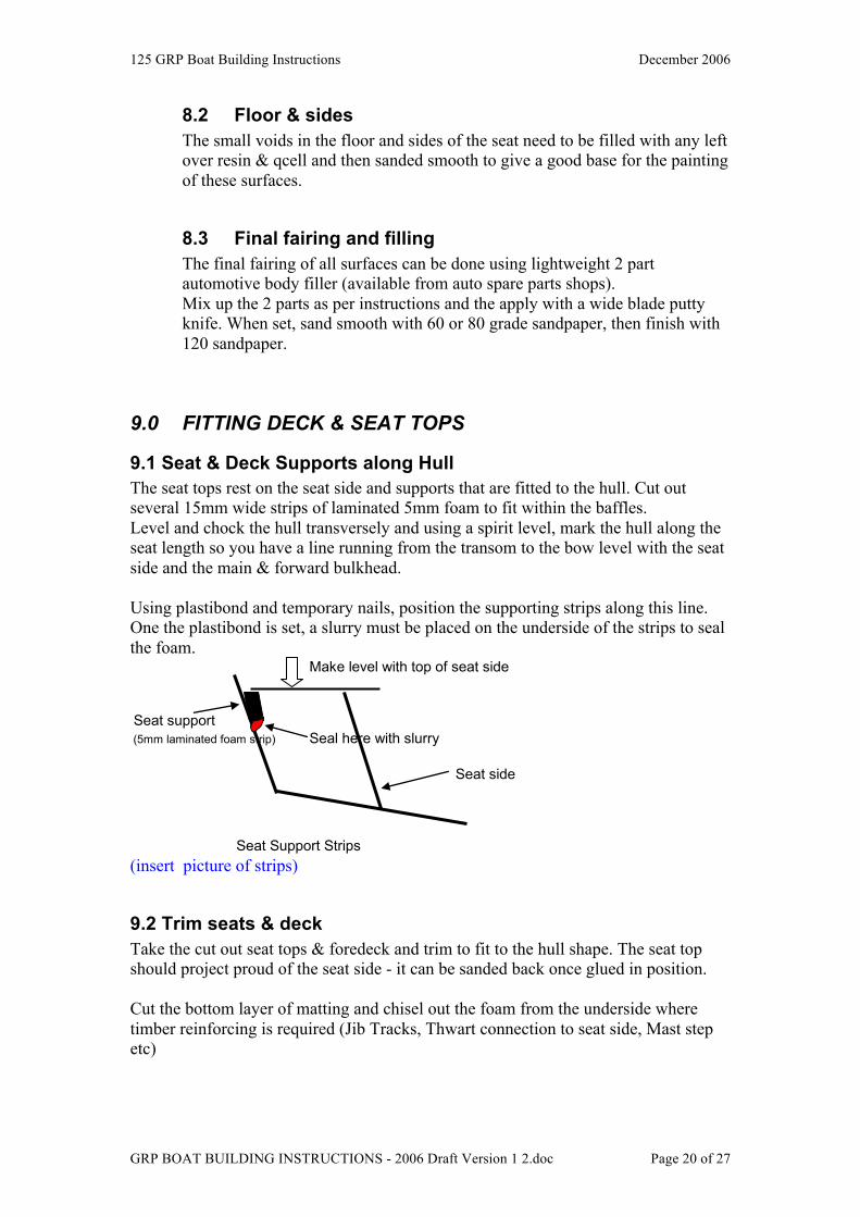
9.1 Seat & Deck Supports along Hull The seat tops rest on the seat side and supports that are fitted to the hull. Cut out several 15mm wide strips of laminated 5mm foam to fit within the baffles. Level and chock the hull transversely and using a spirit level, mark the hull along the seat length so you have a line running from the transom to the bow level with the seat side and the main & forward bulkhead. Using plastibond and temporary nails, position the supporting strips along this line. One the plastibond is set, a slurry must be placed on the underside of the strips to seal the foam.
Make level with top of seat side
Seat support(5mm laminated foam strip) Seal here with slurry
Seat side
Seat Support Strips (insert picture of strips)
9.2 Trim seats & deck Take the cut out seat tops & foredeck and trim to fit to the hull shape. The seat top should project proud of the seat side - it can be sanded back once glued in position. Cut the bottom layer of matting and chisel out the foam from the underside where timber reinforcing is required (Jib Tracks, Thwart connection to seat side, Mast step etc)
125 GRP Boat Building Instructions December 2006
GRP BOAT BUILDING INSTRUCTIONS - 2006 Draft Version 1 2.doc Page 21 of 27
Score the timber surfaces, and glue timber reinforcing into position. Where the timber surface is exposed, (eg mast step support) it must be sealed with a coat of resin to prevent water absorption.
9.3 Glue Seat tops & Foredeck This is your last chance to access the tanks, so make sure they are clean, free from debris and there is nothing else to do before they are sealed. Note: you should drill a 3 mm hole at the top of the forward bulkhead each side of the web to enable the air pressure to equalize in each forward tank. Glue a supporting strip of 8mm laminated foam along the Web to provide a wider platform for the foredeck halves to be glued to. Glue the seat tops and foredeck in position, by placing a slurry mixture along all joining surfaces place house bricks on top to firmly hold the panels in position. Once dry, a fillet of slurry should be placed along the seat edge and foredeck where it meets the hull and the edges can be sanded back to fit the profile.
9.4 Sanding taped joints The taped joints must be sanded to give a smooth fairing from the tape to the panel. Use an orbital sander to achieve this finish.
10.0 BOW COVER The Bow cover should be cut from 5mm laminated foam as per the pattern (See Section 6.1) The vertical support piece between the hull sides can be made using 2 pieces of 5mm laminated foam glued together. Insert Photo Glue vertical piece between hulls in position first, then cut and shape bow cover to fit.
11.0 GLASSING GUNWALES & EXPOSED JOINTS
11.1 Glassing Gunwales The gunwales have 2 layers of matting from the hull build and need to be strengthened by the addition of 2 to 4 more layers of resin and fibreglass tape. Mix up a resin, apply to gunwales and lay tape along the gunwales. Three separate lengths are required so the tape will follow the curve of the hull. Sand each layer smooth before proceeding with the next layer.

125 GRP Boat Building Instructions December 2006
GRP BOAT BUILDING INSTRUCTIONS - 2006 Draft Version 1 2.doc Page 22 of 27
11.2 Glassing Exposed Joints The exposed joints must be sealed with fibreglass tape. These joints are: Hull side to seat top and fore deck Seat top to seat side Seat side to floor Main bulkhead to floor Foredeck to main bulkhead Transom to Floor Centrecase to floor Mix up a resin mixture, apply tape (weight of tape?) to each joint. When dry, sand smooth so that it feathers back into the panel.
12.0 CUT OUTS
12.1 Inspection Hatches Cut out hole in Main bulkhead and seat sides for the inspection hatches. Four hatches are required – 2 in main bulkhead, one each side tank. (see Rule zzz) The side tank hole should be positioned between the main bulkhead and the thwart so you can access inside the tank to fit the Jib tracks, and fittings near the thwart. Purchase the hatches first so you can use as a pattern for the correct size. The exposed foam should be coated with resin so it doesn’t absorb water.
12.2 Hand holes in transom Hand holes are cut in the transom - these should be flush with the seat to allow water on the seats to drain. Use a jig saw to cut – check Rule for min/max size of holes
12.3 Scuppers Scuppers are cut at the bottom of the transom to allow water to be drained quickly in the event of a capsize. Check Rule for min/max size of holes. Coat the inside of the hole where the foam in exposed with resin to ensure the foam does not absorb water. (Add description of Perspex flaps)
12.4 Venturi Bailers Purchase the bailer to use as a template. Place approx under the thwart, about 40 mm off the centrecase. Drill a hole then use a jigsaw to cut out the hole. Make the bailer a neat fit, allowing about 1mm all round for paint. Drill the four holes for the bolts, remember to countersink the holes underneath the hull
125 GRP Boat Building Instructions December 2006
GRP BOAT BUILDING INSTRUCTIONS - 2006 Draft Version 1 2.doc Page 23 of 27
13.0 SANDING EXTERIOR OF HULL Fill any small defects in exterior of the hull using a mixture of resin & q-cell. Sand smooth using an orbital sander and sanding block. Use 80 and then 120 grade discs/strip. If there are any hollow areas, they need to be filled by cutting away a small piece of the outer glass layer and then squeezing a mixture of resin & qcell into the space. Keep filling and sanding until the surface is smooth. The final finish of the hull will depend on how much work is put in at this stage. The final fairing of all surfaces can be done using lightweight 2 part automotive body filler (available from auto spare parts shops). Mix up the 2 parts as per instructions and the apply with a wide blade putty knife. When set, sand smooth with 60 or 80 grade sandpaper, then finish with 120 sandpaper. When you are happy with the result, the boat is ready for painting. Typical build time frame from commencement to completion of hull ready to paint is 8 weeks. (See Appendix for approx estimate of the manhours involved in each stage.)
14.0 PAINTING It is recommended that painting of the completed hull be carried out by a professional to give the best appearance. See Appendix C for a list of recommended suppliers. The cost can be reduced by the amount of preparation you out in before taking to the paint shop e.g. sanding with wet & dry and undercoating. You will need to specify which areas you want painted with non slip paint additive – generally the floor and the section of the gunwale where the crew trapezes on.
15.0 FITOUT & RIGGING HULL
15.1 Fittings
14.2 Rigging Shrouds: Mast wire Trapeze 3.5m x 3mm Spectra Sheets: Main Halyard x 3mm Spectra Vang 3 m x 4mm Spectra Boom outhaul 3m x 4mm double braid Jib down haul 2m x 4mm double braid Spinnaker Haylard 14m x 4mm double braid Spinnaker guy& sheet 15m x 6mm double braid (or Spectra) Barber hauler 2.5m x 4mm Spectra Pole uphaul 6m x 4mm double braid
125 GRP Boat Building Instructions December 2006
GRP BOAT BUILDING INSTRUCTIONS - 2006 Draft Version 1 2.doc Page 24 of 27
Pole bridle 3m x 4mm double braid Traveller 5m x 5mm double braid
16.0 BOOM, MAST & SPINNAKER POLE
16.1 Mast Mast sections are available from the 125 Association.
16.2 Boom Boom sections are available from the 125 Association.
16.3 Spinnaker Pole Spinnaker Pole sections are available from the 125 Association.
17.0 CENTREBOARD, RUDDER Centreboards and rudder blades are available from the Victorian 125 Association. These are commercially manufactured of timber sheathed in fibreglass. Other suppliers are listed in Appendix C.
18.0 SAILS Sails can be purchased from any sailmaker - recommended suppliers that are 125 sailors are shown in Appendix C.
17.0 BEACH TROLLEY You will need a beach trolley for easy launching and retrieving of your 125. This can made up from aluminium or stainless steel framing or they can be purchased from commercial builders. (insert picture) See Appendix C for recommended suppliers
18.0 TRAILER
19.0 COST ESTIMATE An approx cost estimate is shown below for an amateur built boat with all new fittings. (centreboard, rudder, mast, boom, sails, fittings etc).

125 GRP Boat Building Instructions December 2006
GRP BOAT BUILDING INSTRUCTIONS - 2006 Draft Version 1 2.doc Page 25 of 27
The cost can be reduced by taking the mast, sails and fittings from an old hull. Many 125 GRP builders are replacing their existing old timber hull with a new GRP hull and transfer the rig from the old boat to the new hull.
125 GRP Boat Building Instructions December 2006
GRP BOAT BUILDING INSTRUCTIONS - 2006 Draft Version 1 2.doc Page 26 of 27
APPENDIX A
Reference Documents (insert 125 Measurement rules here) Note – be sure to check the 125 Association Website for the latest copy of the 125 Rules (www.125assoc.com)
APPENDIX B
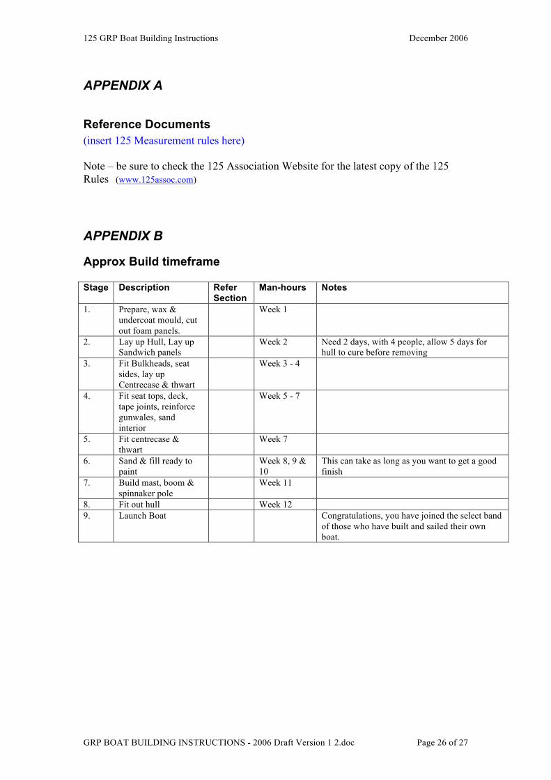
Approx Build timeframe Stage Description Refer
Section Man-hours Notes
1. Prepare, wax & undercoat mould, cut out foam panels.
Week 1
2. Lay up Hull, Lay up Sandwich panels
Week 2 Need 2 days, with 4 people, allow 5 days for hull to cure before removing
3. Fit Bulkheads, seat sides, lay up Centrecase & thwart
Week 3 - 4
4. Fit seat tops, deck, tape joints, reinforce gunwales, sand interior
Week 5 - 7
5. Fit centrecase & thwart
Week 7
6. Sand & fill ready to paint
Week 8, 9 & 10
This can take as long as you want to get a good finish
7. Build mast, boom & spinnaker pole
Week 11
8. Fit out hull Week 12 9. Launch Boat Congratulations, you have joined the select band
of those who have built and sailed their own boat.
125 GRP Boat Building Instructions December 2006
GRP BOAT BUILDING INSTRUCTIONS - 2006 Draft Version 1 2.doc Page 27 of 27
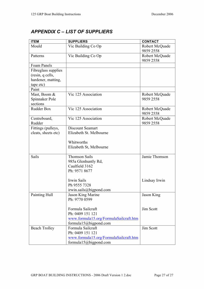
APPENDIX C – LIST OF SUPPLIERS ITEM SUPPLIERS CONTACT Mould Vic Building Co Op Robert McQuade
9859 2558 Patterns Vic Building Co Op Robert McQuade
9859 2558 Foam Panels Fibreglass supplies (resin, q cells, hardener, matting, tape etc)
Paint Mast, Boom & Spinnaker Pole sections
Vic 125 Association Robert McQuade 9859 2558
Rudder Box Vic 125 Association Robert McQuade 9859 2558
Centreboard, Rudder
Vic 125 Association Robert McQuade 9859 2558
Fittings (pulleys, cleats, sheets etc)
Discount Seamart Elizabeth St. Melbourne Whitworths Elizabeth St, Melbourne
Sails Thomson Sails 985a Glenhuntly Rd, Caulfield 3162 Ph: 9571 8677 Irwin Sails Ph 9555 7328 [email protected]
Jamie Thomson Lindsay Irwin
Painting Hull Jason King Marine Ph: 9770 0599 Formula Sailcraft Ph: 0409 151 121 www.formula15.org/FormulaSailcraft.htm [email protected]
Jason King Jim Scott
Beach Trolley Formula Sailcraft Ph: 0409 151 121 www.formula15.org/FormulaSailcraft.htm [email protected]
Jim Scott