Embed Size (px)
Citation preview
User Manual
ADAM-4572, EKI-1221,EKI-1222, EKI-1224, EKI-1221D, EKI-1222D
1/2/4-port Modbus Gateway

CopyrightThe documentation and the software included with this product are copyrighted 2010by Advantech Co., Ltd. All rights are reserved. Advantech Co., Ltd. reserves the rightto make improvements in the products described in this manual at any time withoutnotice. No part of this manual may be reproduced, copied, translated or transmittedin any form or by any means without the prior written permission of Advantech Co.,Ltd. Information provided in this manual is intended to be accurate and reliable. How-ever, Advantech Co., Ltd. assumes no responsibility for its use, nor for any infringe-ments of the rights of third parties, which may result from its use.
AcknowledgementsIntel and Pentium are trademarks of Intel Corporation.Microsoft Windows and MS-DOS are registered trademarks of Microsoft Corp.All other product names or trademarks are properties of their respective owners.
Product Warranty (2 years)Advantech warrants to you, the original purchaser, that each of its products will befree from defects in materials and workmanship for two years from the date of pur-chase. This warranty does not apply to any products which have been repaired or altered bypersons other than repair personnel authorized by Advantech, or which have beensubject to misuse, abuse, accident or improper installation. Advantech assumes noliability under the terms of this warranty as a consequence of such events.Because of Advantech’s high quality-control standards and rigorous testing, most ofour customers never need to use our repair service. If an Advantech product is defec-tive, it will be repaired or replaced at no charge during the warranty period. For out-of-warranty repairs, you will be billed according to the cost of replacement materials,service time and freight. Please consult your dealer for more details.If you think you have a defective product, follow these steps:1. Collect all the information about the problem encountered. (For example, CPU
speed, Advantech products used, other hardware and software used, etc.) Note anything abnormal and list any onscreen messages you get when the problem occurs.
2. Call your dealer and describe the problem. Please have your manual, product, and any helpful information readily available.
3. If your product is diagnosed as defective, obtain an RMA (return merchandize authorization) number from your dealer. This allows us to process your return more quickly.
4. Carefully pack the defective product, a fully-completed Repair and Replacement Order Card and a photocopy proof of purchase date (such as your sales receipt) in a shippable container. A product returned without proof of the purchase date is not eligible for warranty service.
5. Write the RMA number visibly on the outside of the package and ship it prepaid to your dealer.
Part No. 2003122102 Edition 3Printed in Taiwan July 2010
ADAM-4572 & EKI-122X Series User Manual ii

CE
This product has passed the CE test for environmental specifications when shieldedcables are used for external wiring. We recommend the use of shielded cables. Thiskind of cable is available from Advantech. Please contact your local supplier forordering information.
CE
This product has passed the CE test for environmental specifications. Test conditionsfor passing included the equipment being operated within an industrial enclosure. Inorder to protect the product from being damaged by ESD (Electrostatic Discharge)and EMI leakage, we strongly recommend the use of CE-compliant industrial enclo-sure products.
FCC Class A
Note: This equipment has been tested and found to comply with the limits for a ClassA digital device, pursuant to part 15 of the FCC Rules. These limits are designed toprovide reasonable protection against harmful interference when the equipment isoperated in a commercial environment. This equipment generates, uses, and canradiate radio frequency energy and, if not installed and used in accordance with theinstruction manual, may cause harmful interference to radio communications. Opera-tion of this equipment in a residential area is likely to cause harmful interference inwhich case the user will be required to correct the interference at his own expense.
Technical Support and Assistance1. Visit the Advantech web site at www.advantech.com/support where you can find
the latest information about the product.2. Contact your distributor, sales representative, or Advantech's customer service
center for technical support if you need additional assistance. Please have the following information ready before you call:– Product name and serial number– Description of your peripheral attachments– Description of your software (operating system, version, application software,
etc.)– A complete description of the problem– The exact wording of any error messages
iii ADAM-4572 & EKI-122X Series User Manual

Safety Instructions1. Read these safety instructions carefully.2. Keep this User Manual for later reference.3. Disconnect this equipment from any AC outlet before cleaning. Use a damp
cloth. Do not use liquid or spray detergents for cleaning.4. For plug-in equipment, the power outlet socket must be located near the equip-
ment and must be easily accessible.5. Keep this equipment away from humidity.6. Put this equipment on a reliable surface during installation. Dropping it or letting
it fall may cause damage.7. The openings on the enclosure are for air convection. Protect the equipment
from overheating. DO NOT COVER THE OPENINGS.8. Make sure the voltage of the power source is correct before connecting the
equipment to the power outlet.9. Position the power cord so that people cannot step on it. Do not place anything
over the power cord.10. All cautions and warnings on the equipment should be noted.11. If the equipment is not used for a long time, disconnect it from the power source
to avoid damage by transient overvoltage.12. Never pour any liquid into an opening. This may cause fire or electrical shock.13. Never open the equipment. For safety reasons, the equipment should be
opened only by qualified service personnel.14. If one of the following situations arises, get the equipment checked by service
personnel:– The power cord or plug is damaged.– Liquid has penetrated into the equipment.– The equipment has been exposed to moisture.– The equipment does not work well, or you cannot get it to work according to
the user's manual.– The equipment has been dropped and damaged.– The equipment has obvious signs of breakage.
15. DO NOT LEAVE THIS EQUIPMENT IN AN ENVIRONMENT WHERE THE STORAGE TEMPERATURE MAY GO BELOW -20° C (-4° F) OR ABOVE 60° C (140° F). THIS COULD DAMAGE THE EQUIPMENT. THE EQUIPMENT SHOULD BE IN A CONTROLLED ENVIRONMENT.
16. CAUTION: DANGER OF EXPLOSION IF BATTERY IS INCORRECTLY REPLACED. REPLACE ONLY WITH THE SAME OR EQUIVALENT TYPE RECOMMENDED BY THE MANUFACTURER, DISCARD USED BATTERIES ACCORDING TO THE MANUFACTURER'S INSTRUCTIONS.
17. The sound pressure level at the operator's position according to IEC 704-1:1982 is no more than 70 dB (A).
DISCLAIMER: This set of instructions is given according to IEC 704-1. Advantechdisclaims all responsibility for the accuracy of any statements contained herein.
ADAM-4572 & EKI-122X Series User Manual iv

1.1 Overview ................................................................................................... 21.2 Features .................................................................................................... 21.3 Package Check List .................................................................................. 3
Chapter 2 Getting Started.....................................52.1 Understanding Modbus Gateways ............................................................ 6
2.1.1 Protocol Overview......................................................................... 6Figure 2.1 Modbus System Architecture 1................................... 7Figure 2.2 Modbus System Architecture 2................................... 7
2.1.2 Modbus RTU................................................................................. 82.1.3 Modbus ASCII............................................................................... 8
Table 2.1: Comparison of Modbus RTU and ASCII Modes......... 82.1.4 Modbus TCP................................................................................. 8
2.2 Specifications ............................................................................................ 92.2.1 EKI-1221/1222/1224 ..................................................................... 92.2.2 EKI-1221D/1222D....................................................................... 102.2.3 ADAM-4572 ................................................................................ 11
2.3 Hardware................................................................................................. 122.3.1 LED Indicators ............................................................................ 12
Table 2.2: EKI-1221/1222/1224, EKI-1221D/1222D LED Indica-tors............................................................................ 12
Table 2.3: ADAM-4572 LED Indicators ..................................... 122.3.2 Dimensions (Units: mm).............................................................. 13
Figure 2.3 Front View of EKI-1221 ............................................ 13Figure 2.4 Side View of EKI-1221.............................................. 13Figure 2.5 Back View of EKI-1221............................................. 14Figure 2.6 Top View of EKI-1221............................................... 14Figure 2.7 Front View of EKI-1222 ............................................ 15Figure 2.8 Side View of EKI-1222.............................................. 15Figure 2.9 Back View of EKI-1222............................................. 16Figure 2.10Top View of EKI-1222............................................... 16Figure 2.11Front View of EKI-1224 ............................................ 17Figure 2.12Side View of EKI-1224.............................................. 17Figure 2.13Back View of EKI-1224............................................. 18Figure 2.14Top View of EKI-1224............................................... 18Figure 2.15Front View of EKI-1221D.......................................... 19Figure 2.16Side View of EKI-1221D........................................... 19Figure 2.17Back View of EKI-1221D .......................................... 20Figure 2.18Top View of EKI-1221D ............................................ 20Figure 2.19Front View of EKI-1222D.......................................... 21Figure 2.20Side View of EKI-1222D........................................... 21Figure 2.21Back View of EKI-1222D .......................................... 22Figure 2.22Top View of EKI-1222D ............................................ 22Figure 2.23Front View of ADAM-4572........................................ 23Figure 2.24Back View of ADAM-4572 ........................................ 23Figure 2.25Bottom View of ADAM-4572..................................... 24Figure 2.26Side View of ADAM-4572 ......................................... 24
2.4 Connecting Hardware ............................................................................. 252.4.1 Choosing the Location ................................................................ 25
Figure 2.27Combine the Metal Mounting Kit .............................. 25Figure 2.28ADAM-4572 Panel Mounting Bracket Dimensions ... 26Figure 2.29ADAM-4572 Panel Mounting .................................... 26
v ADAM-4572 & EKI-122X Series User Manual
Figure 2.30DIN-rail Step 1.......................................................... 27Figure 2.31DIN-rail Step 2.......................................................... 27Figure 2.32DIN-rail Adapter........................................................ 28Figure 2.33DIN-rail Mounting ..................................................... 28
2.4.2 Connecting Power ...................................................................... 29Figure 2.34Power Connector...................................................... 29
2.4.3 Connecting Serial Devices.......................................................... 29Figure 2.35EKI-122X series Serial Port Pin Assignments.......... 29
2.4.4 Connecting to a Host or the Network.......................................... 302.4.5 ADAM-4572 Serial Port Wiring ................................................... 30
Figure 2.36Wiring RS-232 Connection....................................... 30Figure 2.37Wiring RS-485 Connection....................................... 31Figure 2.38Wiring RS-422 Connection....................................... 31
Chapter 3 Configuration .................................... 333.1 Installing the Configuration Utility............................................................ 343.2 Starting the Configuration Utility ............................................................. 373.3 Discovering Modbus Gateways .............................................................. 38
3.3.1 Auto Searching ........................................................................... 383.3.2 Clear Device List and Search Again ........................................... 413.3.3 Manual Appending...................................................................... 41
3.4 Setting Ethernet Parameters................................................................... 423.5 Setting Serial Communication Parameters ............................................. 43
3.5.1 Basic Configuration..................................................................... 443.5.2 Operation Configuration.............................................................. 46
3.6 Function Accessible Setting.................................................................... 493.7 Monitoring Modbus Status ...................................................................... 503.8 Administrator Setting............................................................................... 50
3.8.1 Import/Export Serial Port Setting ................................................ 513.8.2 Locate the Modbus Data Gateway ............................................. 513.8.3 Lock Device ................................................................................ 523.8.4 Restore to Factory Default Settings............................................ 533.8.5 Update Firmware ........................................................................ 54
ADAM-4572 & EKI-122X Series User Manual vi

Chapter 1
1 Introduction
1.1 OverviewAdvantech’s ADAM-4572 and EKI-1221/1222/1224/1221D/1222D series of ModbusGateways (the following manual will use EKI-122X series instead of complete modelname) are a robust, feature-rich, and cost effective way to integrate of Ethernet andSerial Modbus devices. The ADAM-4572 and EKI-122X series provides one, two orfour serial ports, one or two Ethernet ports, a wide range of power inputs, and acompact slim design, making them an ideal solution for connecting multiple Modbus/RTU and Modbus/ASCII serial devices to Modbus TCP (Ethernet).
Originally developed for PLCs in industrial automation and manufacturing controlapplications, Modbus is one of the most popular open standard protocols in usetoday. The communication mode can be Modbus RTU/ASCII (Serial) or Modbus TCP(Ethernet). Many industrial devices use Modbus as their communication standard.However, the Ethernet-based Modbus protocol is different from the original serial-based protocols that a Modbus Gateway is needed to be a bridge for integration.
The two Ethernet ports allow the EKI-122X series to establish two separatedEthernet connections to two Ethernet domains or two Ethernet switches in the samedomain. Through a dual Ethernet connection, the EKI-122X series greatly improvesthe device connectivity reliability, increase system stability, and simplify theredundant configuration.
The Modbus/RTU and Modbus/ASCII protocols define how a “master” device pollsone or more “slave” devices and write real-time data over RS-232, RS-422, or RS-485 serial data communication. The ADAM-4572 and EKI-122X series provides afeature that can allow users to select master or slave operation for each serial port.The ADAM-4572 and EKI-122X series not only allows Ethernet master can controlserial slaves, but also allow serial masters to control Ethernet or serial slaves.Furthermore, the EKI-122X series can allow both Ethernet and serial slaves to becontrolled by both Ethernet and serial masters.
The ADAM-4572 and EKI-122X series supports various operating modes: RTUMaster, RTU Slave, ASCII Master, and ASCII Slave.
1.2 FeaturesProvides dual 10/100 Mbps auto-sensing Ethernet ports (EKI-122X series only)Integration of Modbus TCP and Modbus RTU/ASCII networksSupports COM port's baud rate up to 921.6 kbpsSupports up to 16 TCP connections and 32 requests simultaneouslySupports 31 slaves (RS-485) per serial portSupports auto-bypass function (EKI-1221D/1222D only)Software selectable RS-232/422/485 communicationAuto searching slave ID over configuration utilityMounts on DIN-rail, wall, or panelClass I, Division 2 certificate for EKI-122X series
ADAM-4572 & EKI-122X Series User Manual 2
Chapter 1
Introduction
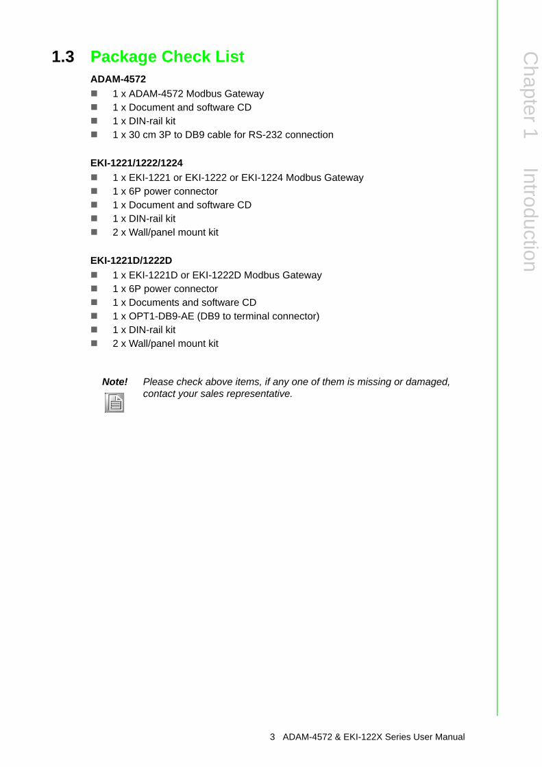
1.3 Package Check ListADAM-4572
1 x ADAM-4572 Modbus Gateway1 x Document and software CD1 x DIN-rail kit1 x 30 cm 3P to DB9 cable for RS-232 connection
EKI-1221/1222/12241 x EKI-1221 or EKI-1222 or EKI-1224 Modbus Gateway1 x 6P power connector1 x Document and software CD1 x DIN-rail kit2 x Wall/panel mount kit
EKI-1221D/1222D1 x EKI-1221D or EKI-1222D Modbus Gateway1 x 6P power connector1 x Documents and software CD1 x OPT1-DB9-AE (DB9 to terminal connector)1 x DIN-rail kit2 x Wall/panel mount kit
Note! Please check above items, if any one of them is missing or damaged, contact your sales representative.
3 ADAM-4572 & EKI-122X Series User Manual

ADAM-4572 & EKI-122X Series User Manual 4

Chapter 2
2 Getting Started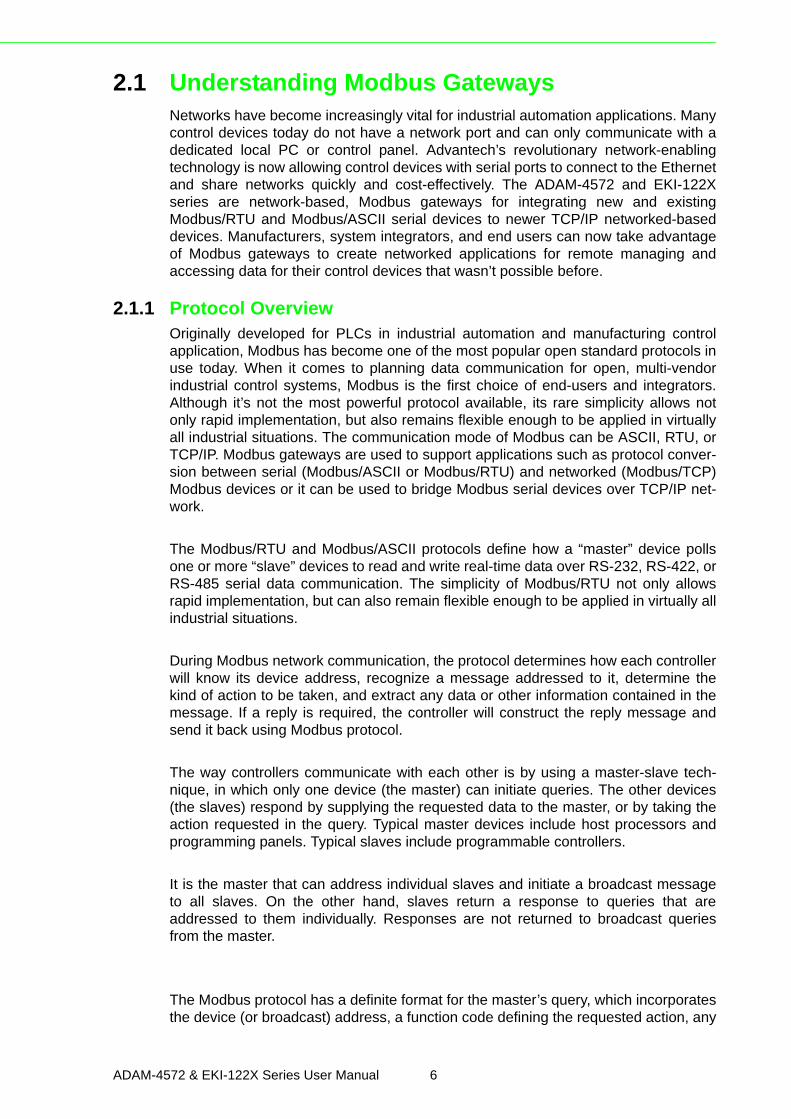
2.1 Understanding Modbus GatewaysNetworks have become increasingly vital for industrial automation applications. Manycontrol devices today do not have a network port and can only communicate with adedicated local PC or control panel. Advantech’s revolutionary network-enablingtechnology is now allowing control devices with serial ports to connect to the Ethernetand share networks quickly and cost-effectively. The ADAM-4572 and EKI-122Xseries are network-based, Modbus gateways for integrating new and existingModbus/RTU and Modbus/ASCII serial devices to newer TCP/IP networked-baseddevices. Manufacturers, system integrators, and end users can now take advantageof Modbus gateways to create networked applications for remote managing andaccessing data for their control devices that wasn’t possible before.
2.1.1 Protocol OverviewOriginally developed for PLCs in industrial automation and manufacturing controlapplication, Modbus has become one of the most popular open standard protocols inuse today. When it comes to planning data communication for open, multi-vendorindustrial control systems, Modbus is the first choice of end-users and integrators.Although it’s not the most powerful protocol available, its rare simplicity allows notonly rapid implementation, but also remains flexible enough to be applied in virtuallyall industrial situations. The communication mode of Modbus can be ASCII, RTU, orTCP/IP. Modbus gateways are used to support applications such as protocol conver-sion between serial (Modbus/ASCII or Modbus/RTU) and networked (Modbus/TCP)Modbus devices or it can be used to bridge Modbus serial devices over TCP/IP net-work.
The Modbus/RTU and Modbus/ASCII protocols define how a “master” device pollsone or more “slave” devices to read and write real-time data over RS-232, RS-422, orRS-485 serial data communication. The simplicity of Modbus/RTU not only allowsrapid implementation, but can also remain flexible enough to be applied in virtually allindustrial situations.
During Modbus network communication, the protocol determines how each controllerwill know its device address, recognize a message addressed to it, determine thekind of action to be taken, and extract any data or other information contained in themessage. If a reply is required, the controller will construct the reply message andsend it back using Modbus protocol.
The way controllers communicate with each other is by using a master-slave tech-nique, in which only one device (the master) can initiate queries. The other devices(the slaves) respond by supplying the requested data to the master, or by taking theaction requested in the query. Typical master devices include host processors andprogramming panels. Typical slaves include programmable controllers.
It is the master that can address individual slaves and initiate a broadcast messageto all slaves. On the other hand, slaves return a response to queries that areaddressed to them individually. Responses are not returned to broadcast queriesfrom the master.
The Modbus protocol has a definite format for the master’s query, which incorporatesthe device (or broadcast) address, a function code defining the requested action, any
ADAM-4572 & EKI-122X Series User Manual 6

Chapter 2
Getting
Started
data to be sent, and an error-checking field. The slave’s response message, which isalso constructed using Modbus protocol, contains fields confirming the action taken,any data to be returned, and an error-checking field. If an error occurred in receipt ofthe message, or if the slave is unable to perform the requested action, the slave willconstruct an error message and send it as its response.
The basic system architecture is as below:
Figure 2.1 Modbus System Architecture 1
Figure 2.2 Modbus System Architecture 2
7 ADAM-4572 & EKI-122X Series User Manual
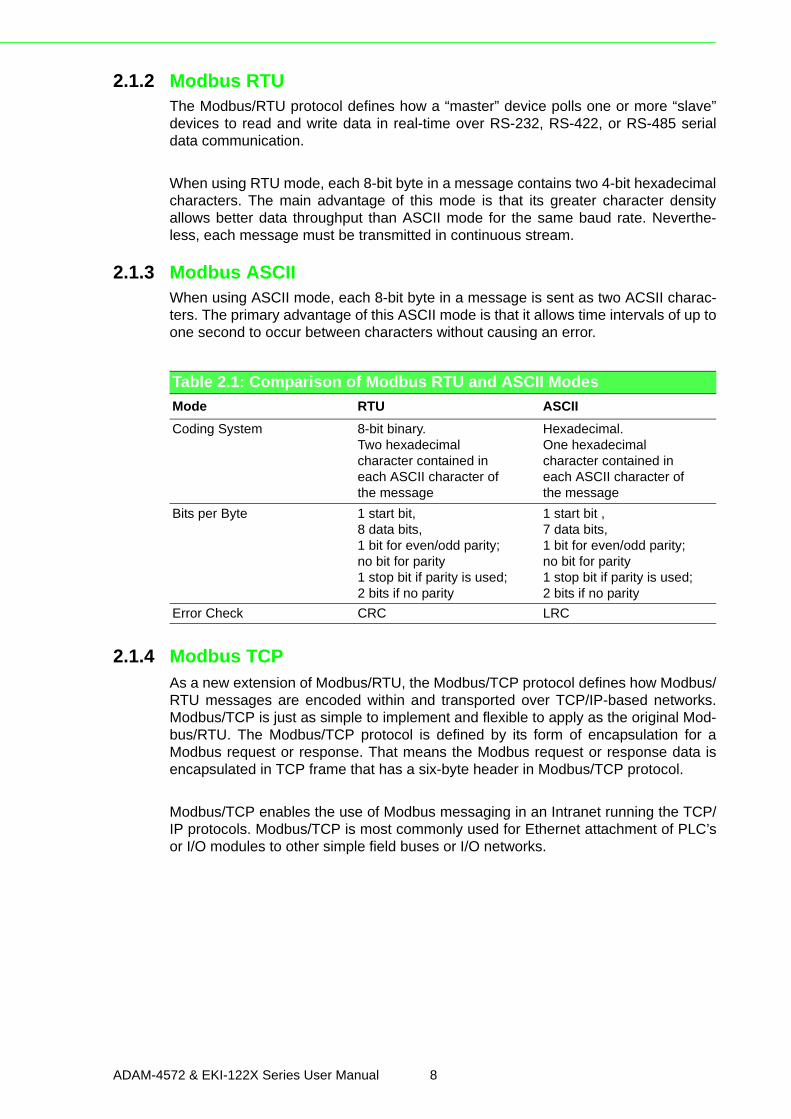
2.1.2 Modbus RTUThe Modbus/RTU protocol defines how a “master” device polls one or more “slave”devices to read and write data in real-time over RS-232, RS-422, or RS-485 serialdata communication.
When using RTU mode, each 8-bit byte in a message contains two 4-bit hexadecimalcharacters. The main advantage of this mode is that its greater character densityallows better data throughput than ASCII mode for the same baud rate. Neverthe-less, each message must be transmitted in continuous stream.
2.1.3 Modbus ASCIIWhen using ASCII mode, each 8-bit byte in a message is sent as two ACSII charac-ters. The primary advantage of this ASCII mode is that it allows time intervals of up toone second to occur between characters without causing an error.
2.1.4 Modbus TCPAs a new extension of Modbus/RTU, the Modbus/TCP protocol defines how Modbus/RTU messages are encoded within and transported over TCP/IP-based networks.Modbus/TCP is just as simple to implement and flexible to apply as the original Mod-bus/RTU. The Modbus/TCP protocol is defined by its form of encapsulation for aModbus request or response. That means the Modbus request or response data isencapsulated in TCP frame that has a six-byte header in Modbus/TCP protocol.
Modbus/TCP enables the use of Modbus messaging in an Intranet running the TCP/IP protocols. Modbus/TCP is most commonly used for Ethernet attachment of PLC’sor I/O modules to other simple field buses or I/O networks.
Table 2.1: Comparison of Modbus RTU and ASCII ModesMode RTU ASCIICoding System 8-bit binary.
Two hexadecimalcharacter contained ineach ASCII character ofthe message
Hexadecimal.One hexadecimalcharacter contained ineach ASCII character ofthe message
Bits per Byte 1 start bit,8 data bits,1 bit for even/odd parity;no bit for parity1 stop bit if parity is used;2 bits if no parity
1 start bit ,7 data bits,1 bit for even/odd parity;no bit for parity1 stop bit if parity is used;2 bits if no parity
Error Check CRC LRC
ADAM-4572 & EKI-122X Series User Manual 8
Chapter 2
Getting
Started
2.2 Specifications
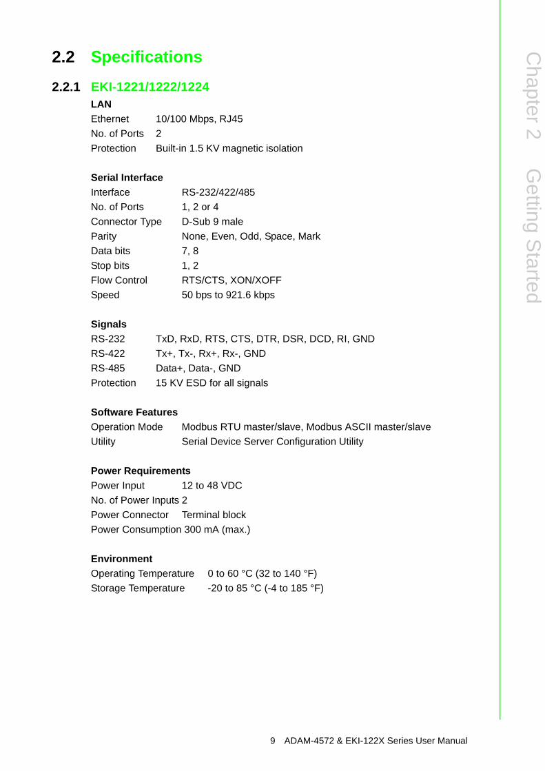
2.2.1 EKI-1221/1222/1224LANEthernet 10/100 Mbps, RJ45No. of Ports 2Protection Built-in 1.5 KV magnetic isolation
Serial InterfaceInterface RS-232/422/485No. of Ports 1, 2 or 4Connector Type D-Sub 9 maleParity None, Even, Odd, Space, MarkData bits 7, 8Stop bits 1, 2Flow Control RTS/CTS, XON/XOFFSpeed 50 bps to 921.6 kbps
SignalsRS-232 TxD, RxD, RTS, CTS, DTR, DSR, DCD, RI, GNDRS-422 Tx+, Tx-, Rx+, Rx-, GNDRS-485 Data+, Data-, GNDProtection 15 KV ESD for all signals
Software FeaturesOperation Mode Modbus RTU master/slave, Modbus ASCII master/slaveUtility Serial Device Server Configuration Utility
Power RequirementsPower Input 12 to 48 VDCNo. of Power Inputs 2Power Connector Terminal blockPower Consumption 300 mA (max.)
EnvironmentOperating Temperature 0 to 60 °C (32 to 140 °F)Storage Temperature -20 to 85 °C (-4 to 185 °F)
9 ADAM-4572 & EKI-122X Series User Manual
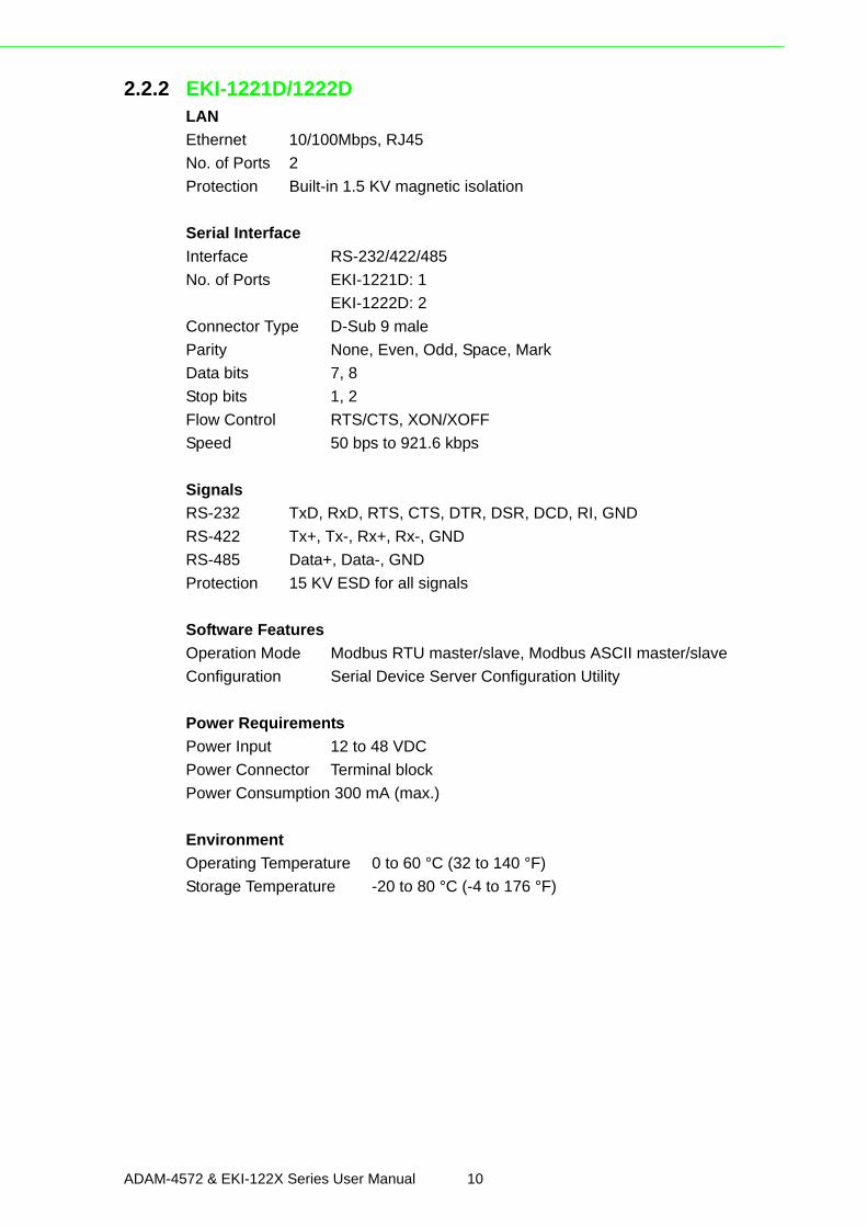
2.2.2 EKI-1221D/1222DLAN Ethernet 10/100Mbps, RJ45No. of Ports 2Protection Built-in 1.5 KV magnetic isolation
Serial InterfaceInterface RS-232/422/485No. of Ports EKI-1221D: 1
EKI-1222D: 2Connector Type D-Sub 9 maleParity None, Even, Odd, Space, MarkData bits 7, 8Stop bits 1, 2Flow Control RTS/CTS, XON/XOFFSpeed 50 bps to 921.6 kbps
Signals RS-232 TxD, RxD, RTS, CTS, DTR, DSR, DCD, RI, GNDRS-422 Tx+, Tx-, Rx+, Rx-, GNDRS-485 Data+, Data-, GNDProtection 15 KV ESD for all signals
Software Features Operation Mode Modbus RTU master/slave, Modbus ASCII master/slaveConfiguration Serial Device Server Configuration Utility
Power RequirementsPower Input 12 to 48 VDCPower Connector Terminal blockPower Consumption 300 mA (max.)
Environment Operating Temperature 0 to 60 °C (32 to 140 °F)Storage Temperature -20 to 80 °C (-4 to 176 °F)
ADAM-4572 & EKI-122X Series User Manual 10
Chapter 2
Getting
Started
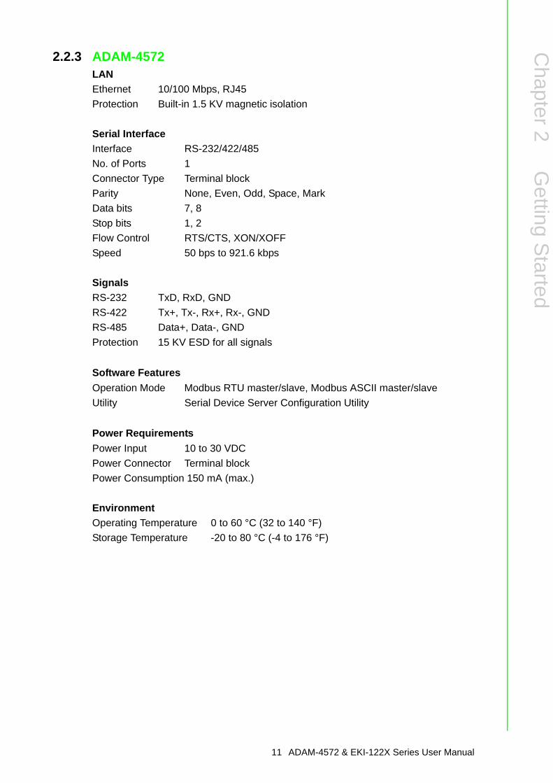
2.2.3 ADAM-4572LANEthernet 10/100 Mbps, RJ45Protection Built-in 1.5 KV magnetic isolation
Serial InterfaceInterface RS-232/422/485No. of Ports 1Connector Type Terminal blockParity None, Even, Odd, Space, MarkData bits 7, 8Stop bits 1, 2Flow Control RTS/CTS, XON/XOFFSpeed 50 bps to 921.6 kbps
SignalsRS-232 TxD, RxD, GNDRS-422 Tx+, Tx-, Rx+, Rx-, GNDRS-485 Data+, Data-, GNDProtection 15 KV ESD for all signals
Software FeaturesOperation Mode Modbus RTU master/slave, Modbus ASCII master/slaveUtility Serial Device Server Configuration Utility
Power RequirementsPower Input 10 to 30 VDCPower Connector Terminal blockPower Consumption 150 mA (max.)
EnvironmentOperating Temperature 0 to 60 °C (32 to 140 °F)Storage Temperature -20 to 80 °C (-4 to 176 °F)
11 ADAM-4572 & EKI-122X Series User Manual
2.3 HardwareThe following instructions will give the overview of ADAM-4572 and EKI-122X serieshardware and its installation.
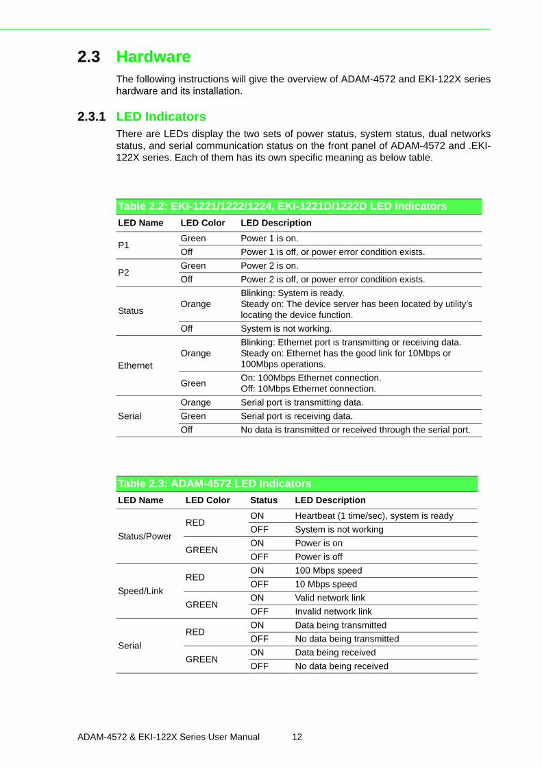
2.3.1 LED IndicatorsThere are LEDs display the two sets of power status, system status, dual networksstatus, and serial communication status on the front panel of ADAM-4572 and .EKI-122X series. Each of them has its own specific meaning as below table.
Table 2.2: EKI-1221/1222/1224, EKI-1221D/1222D LED IndicatorsLED Name LED Color LED Description
P1Green Power 1 is on.Off Power 1 is off, or power error condition exists.
P2Green Power 2 is on.Off Power 2 is off, or power error condition exists.
StatusOrange
Blinking: System is ready.Steady on: The device server has been located by utility’s locating the device function.
Off System is not working.
EthernetOrange
Blinking: Ethernet port is transmitting or receiving data.Steady on: Ethernet has the good link for 10Mbps or 100Mbps operations.
Green On: 100Mbps Ethernet connection.Off: 10Mbps Ethernet connection.
SerialOrange Serial port is transmitting data.Green Serial port is receiving data.Off No data is transmitted or received through the serial port.
Table 2.3: ADAM-4572 LED IndicatorsLED Name LED Color Status LED Description
Status/PowerRED
ON Heartbeat (1 time/sec), system is readyOFF System is not working
GREENON Power is onOFF Power is off
Speed/LinkRED
ON 100 Mbps speedOFF 10 Mbps speed
GREENON Valid network linkOFF Invalid network link
SerialRED
ON Data being transmittedOFF No data being transmitted
GREENON Data being receivedOFF No data being received
ADAM-4572 & EKI-122X Series User Manual 12
Chapter 2
Getting
Started
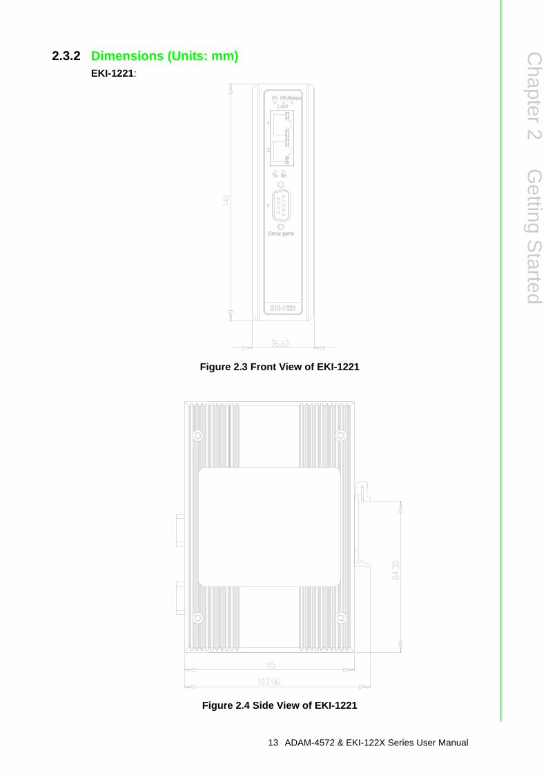
2.3.2 Dimensions (Units: mm)EKI-1221:
Figure 2.3 Front View of EKI-1221
Figure 2.4 Side View of EKI-1221
13 ADAM-4572 & EKI-122X Series User Manual
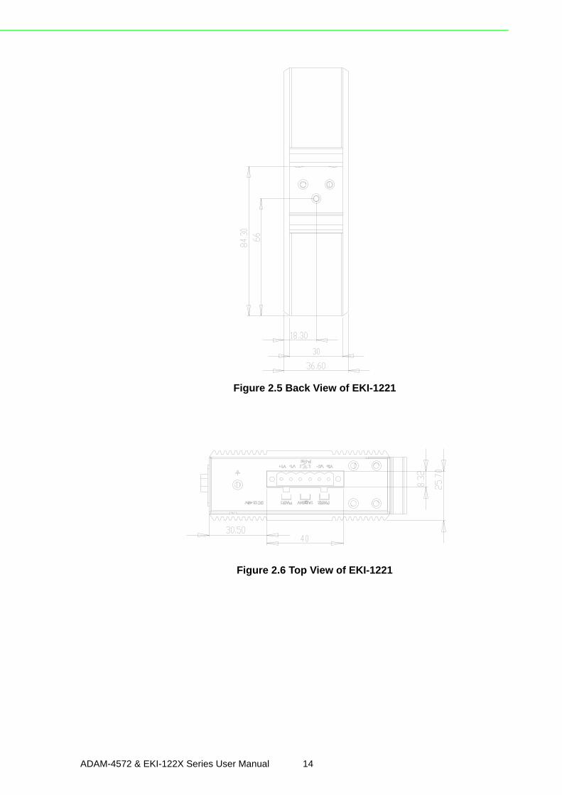
Figure 2.5 Back View of EKI-1221
Figure 2.6 Top View of EKI-1221
ADAM-4572 & EKI-122X Series User Manual 14
Chapter 2
Getting
Started
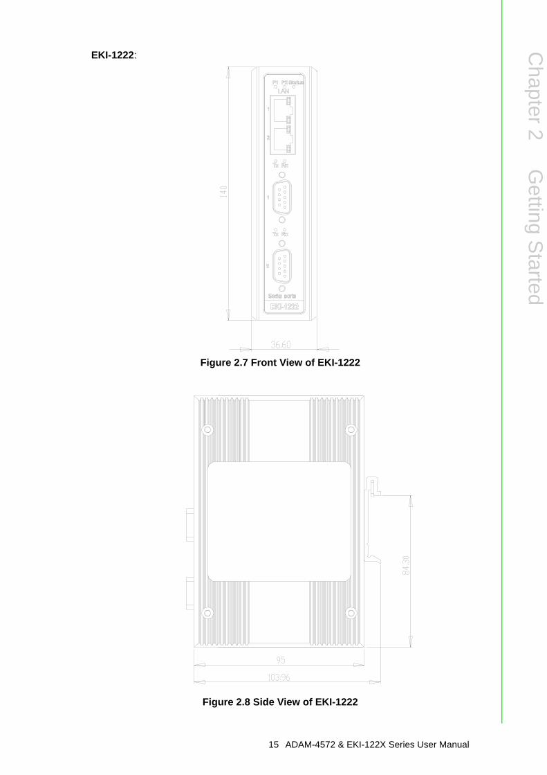
EKI-1222:
Figure 2.7 Front View of EKI-1222
Figure 2.8 Side View of EKI-1222
15 ADAM-4572 & EKI-122X Series User Manual
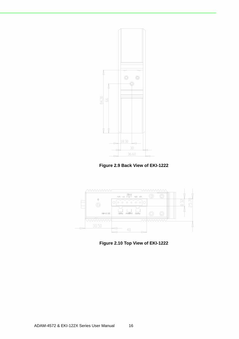
Figure 2.9 Back View of EKI-1222
Figure 2.10 Top View of EKI-1222
ADAM-4572 & EKI-122X Series User Manual 16
Chapter 2
Getting
Started
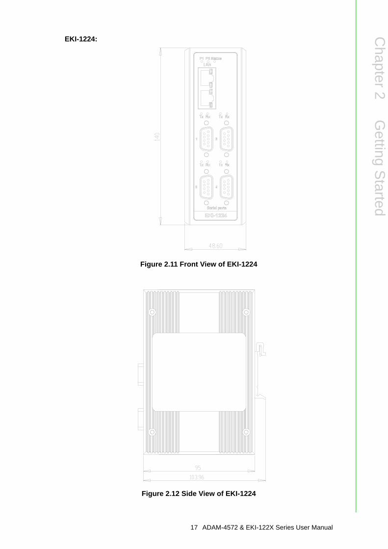
EKI-1224:
Figure 2.11 Front View of EKI-1224
Figure 2.12 Side View of EKI-1224
17 ADAM-4572 & EKI-122X Series User Manual
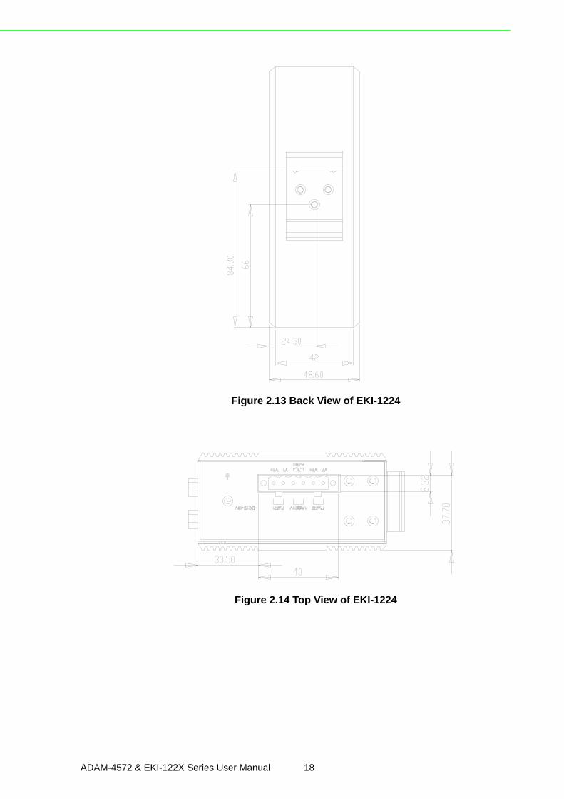
Figure 2.13 Back View of EKI-1224
Figure 2.14 Top View of EKI-1224
ADAM-4572 & EKI-122X Series User Manual 18
Chapter 2
Getting
Started
EKI-1221D:
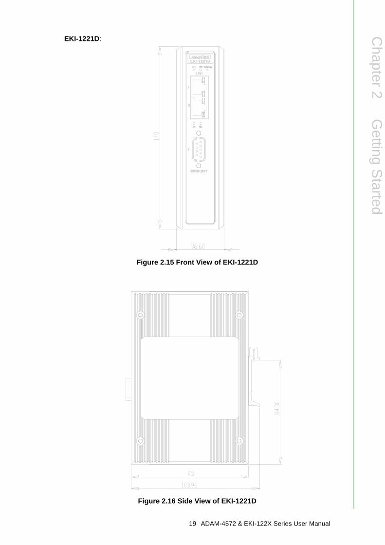
Figure 2.15 Front View of EKI-1221D
Figure 2.16 Side View of EKI-1221D
19 ADAM-4572 & EKI-122X Series User Manual
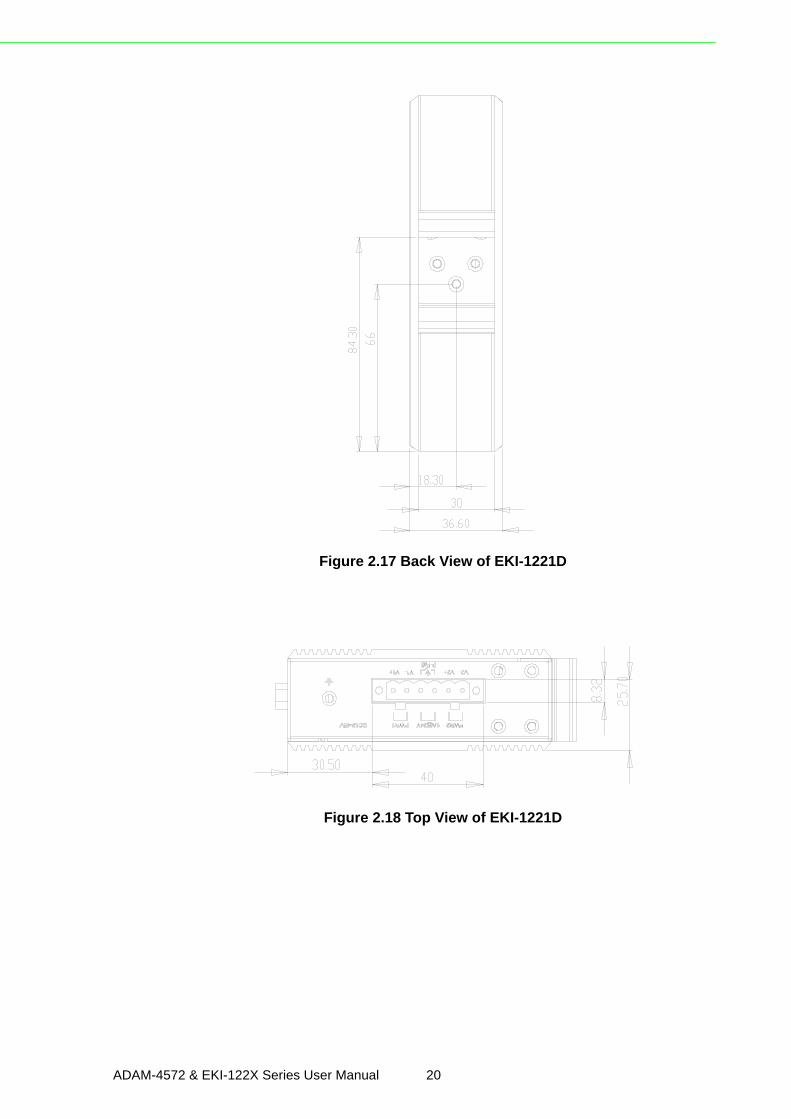
Figure 2.17 Back View of EKI-1221D
Figure 2.18 Top View of EKI-1221D
ADAM-4572 & EKI-122X Series User Manual 20
Chapter 2
Getting
Started
EKI-1222D:
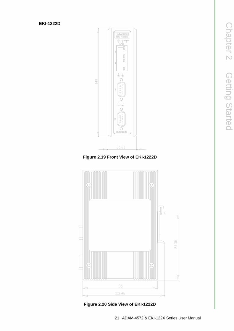
Figure 2.19 Front View of EKI-1222D
Figure 2.20 Side View of EKI-1222D
21 ADAM-4572 & EKI-122X Series User Manual
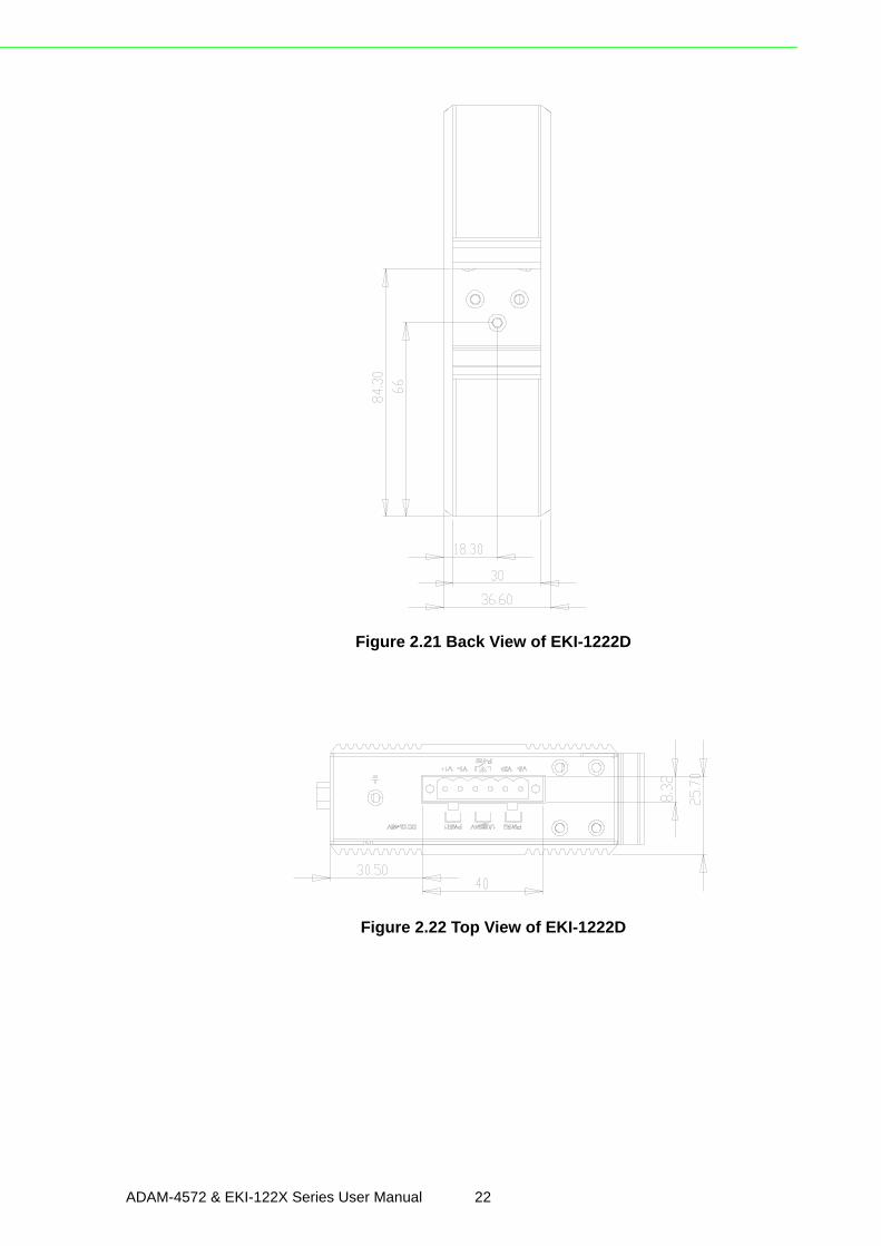
Figure 2.21 Back View of EKI-1222D
Figure 2.22 Top View of EKI-1222D
ADAM-4572 & EKI-122X Series User Manual 22
Chapter 2
Getting
Started
ADAM-4572
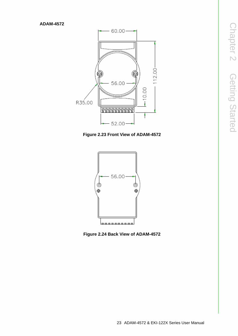
Figure 2.23 Front View of ADAM-4572
Figure 2.24 Back View of ADAM-4572
23 ADAM-4572 & EKI-122X Series User Manual
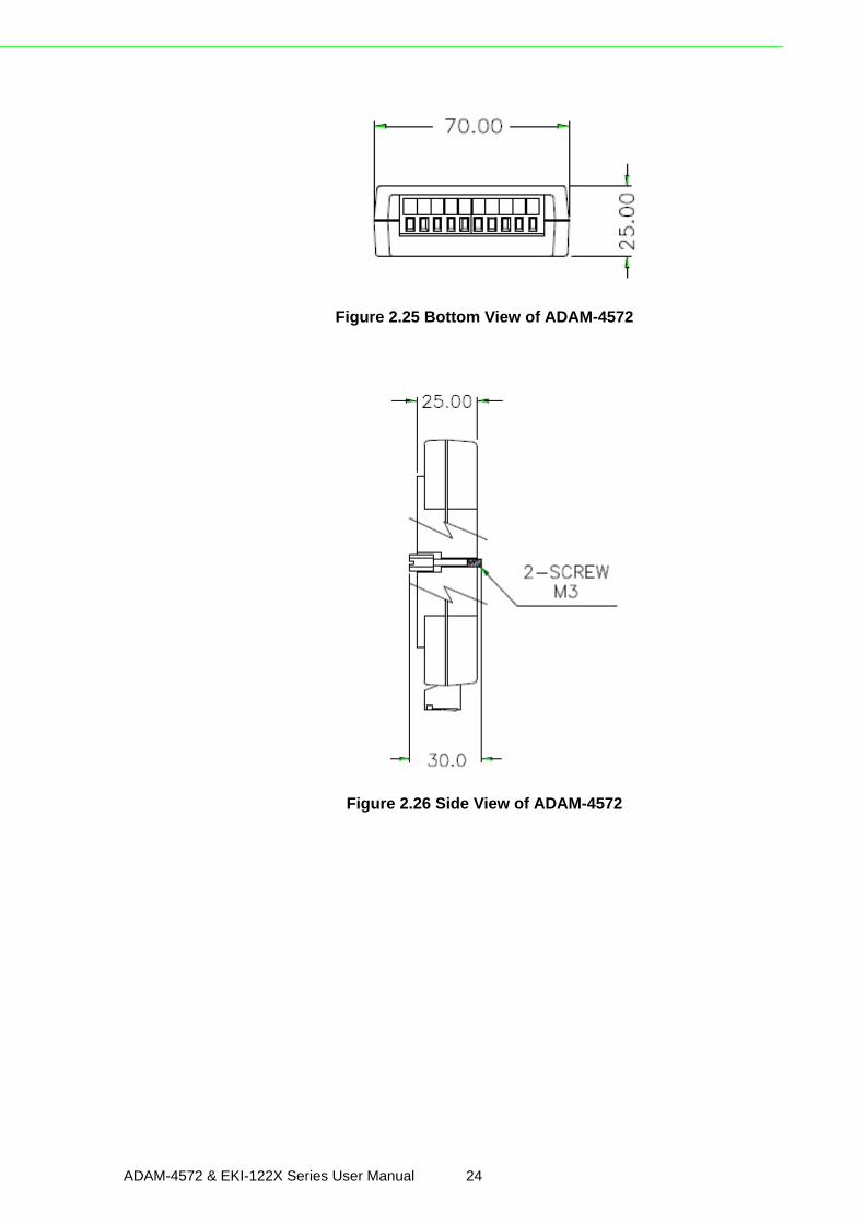
Figure 2.25 Bottom View of ADAM-4572
Figure 2.26 Side View of ADAM-4572
ADAM-4572 & EKI-122X Series User Manual 24

Chapter 2
Getting
Started
2.4 Connecting HardwareIn this instruction, it will explain how to find a proper location for your ModbusGateways, and how to connect to the network, hock up the power cable, and connectto the ADAM-4572 and EKI-122X series.
2.4.1 Choosing the LocationDue to thier innovative design, ADAM-4572 and EKI-122X series can be:
Fixed to a panel mountFixed to a DIN-rail
Panel/Wall MountingThe ADAM-4572 and EKI-122X serie can be attached to a wall using the includedmetal brackets. Each bracket comes with four screws. You can install the ModbusGateways firmly via the components, please see the figures below.
Figure 2.27 Combine the Metal Mounting Kit
25 ADAM-4572 & EKI-122X Series User Manual
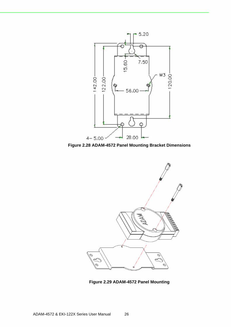
Figure 2.28 ADAM-4572 Panel Mounting Bracket Dimensions
Figure 2.29 ADAM-4572 Panel Mounting
ADAM-4572 & EKI-122X Series User Manual 26

Chapter 2
Getting
Started
DIN-rail MountingThe ADAM-4572, EKI-122X series can be mounted on a standard DIN-rail. The DIN-rail kit is screwed on the Modbus data gateway when out of factory. If the DIN-rail kitis not screwed on the ADAM-4572, EKI-122X series, please screw the DIN-rail kit onthe Modbus data gateway first.
First, hang the Modbus Gateways to the DIN-rail with angle of inclination. See belowfigure.
Figure 2.30 DIN-rail Step 1
Then, let the Modbus Gateways down straight to slide over the rail smoothly.
Figure 2.31 DIN-rail Step 2
27 ADAM-4572 & EKI-122X Series User Manual
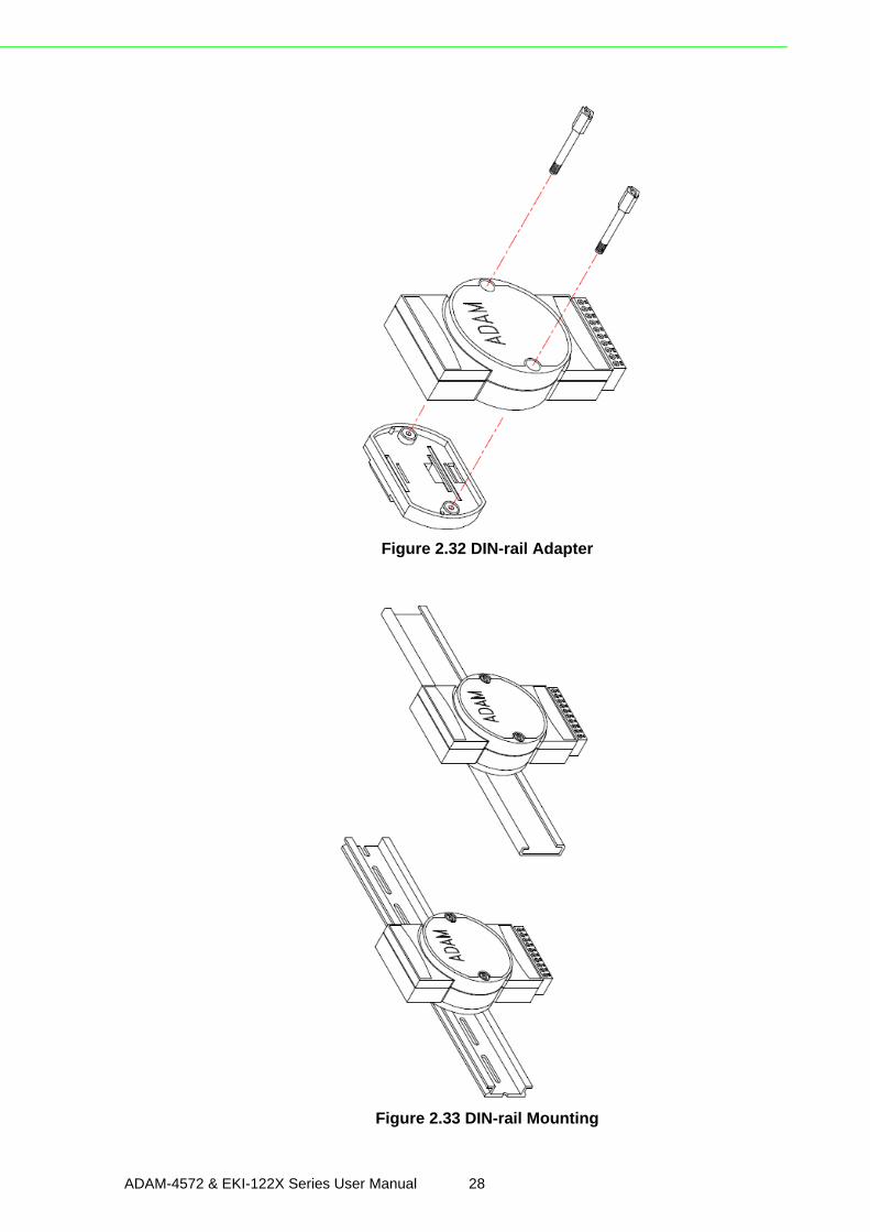
Figure 2.32 DIN-rail Adapter
Figure 2.33 DIN-rail Mounting
ADAM-4572 & EKI-122X Series User Manual 28
Chapter 2
Getting
Started
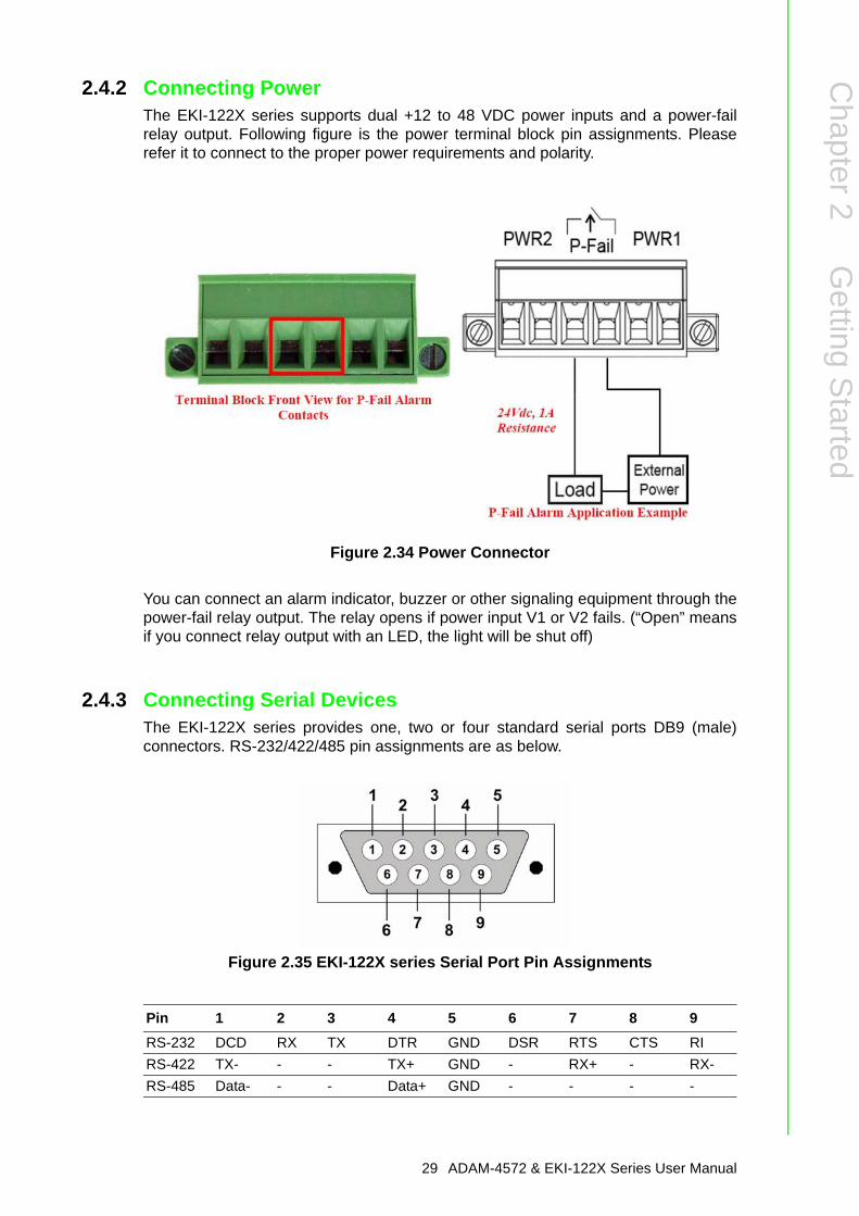
2.4.2 Connecting PowerThe EKI-122X series supports dual +12 to 48 VDC power inputs and a power-failrelay output. Following figure is the power terminal block pin assignments. Pleaserefer it to connect to the proper power requirements and polarity.
Figure 2.34 Power Connector
You can connect an alarm indicator, buzzer or other signaling equipment through thepower-fail relay output. The relay opens if power input V1 or V2 fails. (“Open” meansif you connect relay output with an LED, the light will be shut off)
2.4.3 Connecting Serial DevicesThe EKI-122X series provides one, two or four standard serial ports DB9 (male)connectors. RS-232/422/485 pin assignments are as below.
Figure 2.35 EKI-122X series Serial Port Pin Assignments
Pin 1 2 3 4 5 6 7 8 9RS-232 DCD RX TX DTR GND DSR RTS CTS RIRS-422 TX- - - TX+ GND - RX+ - RX-RS-485 Data- - - Data+ GND - - - -
29 ADAM-4572 & EKI-122X Series User Manual
2.4.4 Connecting to a Host or the NetworkThe EKI-122X series provides two RJ45 connectors with dual independent Ethernetnetworks, and supports 10/100 Mbps transmission speed. The ADAM-4572 and EKI-122X Series will auto detect current transmission speed on the network andconfigure itself accordingly. For normal operation, the ADAM-4572 and EKI-122XSeries can be connected to other hubs or switches through a twisted-pair straightthrough the Ethernet cable. For configuration or troubleshooting purposes, user mayneed to connect the ADAM-4572 and EKI-122X Series directly to the host PC. In thisoperation mode, user can use a crossover Ethernet cable to connect the ADAM-4572and EKI-122X Series to the host PC’s Ethernet connector.For advanced model, EKI-1221D and EKI-1222D, provide two Ethernet ports withone IP address. One port can be used to connect to the network, and the other portcan be used to connect to another Ethernet device (or another EKI-1221D/1222D,like Daisy-Chain structure).
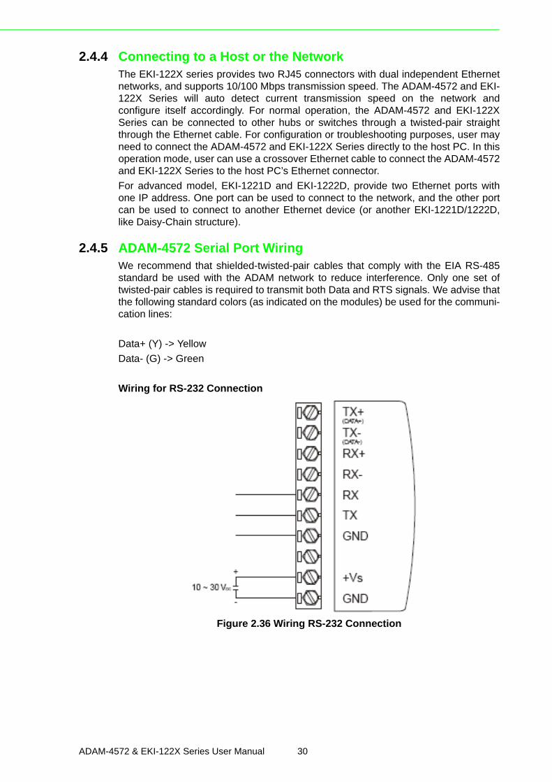
2.4.5 ADAM-4572 Serial Port WiringWe recommend that shielded-twisted-pair cables that comply with the EIA RS-485standard be used with the ADAM network to reduce interference. Only one set oftwisted-pair cables is required to transmit both Data and RTS signals. We advise thatthe following standard colors (as indicated on the modules) be used for the communi-cation lines:
Data+ (Y) -> YellowData- (G) -> Green
Wiring for RS-232 Connection
Figure 2.36 Wiring RS-232 Connection
ADAM-4572 & EKI-122X Series User Manual 30
Chapter 2
Getting
Started
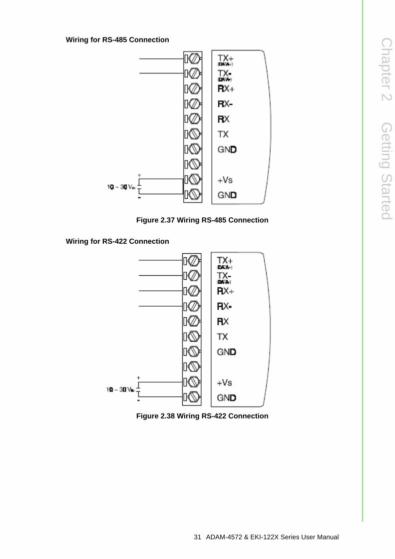
Wiring for RS-485 Connection
Figure 2.37 Wiring RS-485 Connection
Wiring for RS-422 Connection
Figure 2.38 Wiring RS-422 Connection
31 ADAM-4572 & EKI-122X Series User Manual

ADAM-4572 & EKI-122X Series User Manual 32

Chapter 3
3 Configuration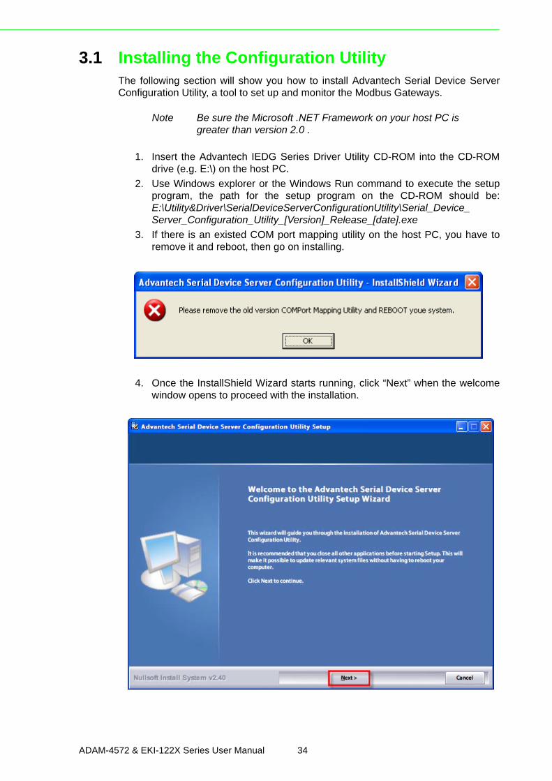
3.1 Installing the Configuration UtilityThe following section will show you how to install Advantech Serial Device ServerConfiguration Utility, a tool to set up and monitor the Modbus Gateways.
1. Insert the Advantech IEDG Series Driver Utility CD-ROM into the CD-ROMdrive (e.g. E:\) on the host PC.
2. Use Windows explorer or the Windows Run command to execute the setupprogram, the path for the setup program on the CD-ROM should be:E:\Utility&Driver\SerialDeviceServerConfigurationUtility\Serial_Device_Server_Configuration_Utility_[Version]_Release_[date].exe
3. If there is an existed COM port mapping utility on the host PC, you have toremove it and reboot, then go on installing.
4. Once the InstallShield Wizard starts running, click “Next” when the welcomewindow opens to proceed with the installation.
Note Be sure the Microsoft .NET Framework on your host PC is greater than version 2.0 .
ADAM-4572 & EKI-122X Series User Manual 34
Chapter 3
Configuration
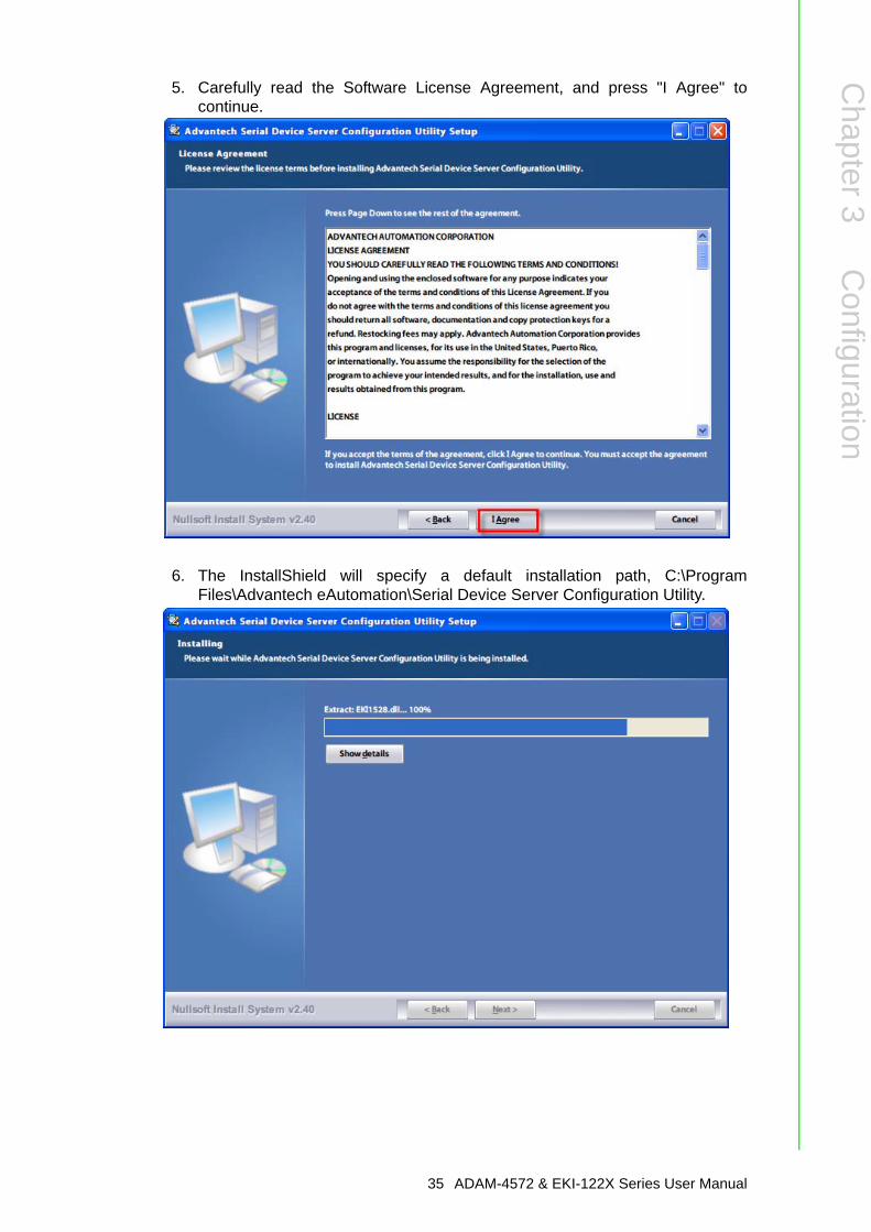
5. Carefully read the Software License Agreement, and press "I Agree" tocontinue.
6. The InstallShield will specify a default installation path, C:\ProgramFiles\Advantech eAutomation\Serial Device Server Configuration Utility.
35 ADAM-4572 & EKI-122X Series User Manual
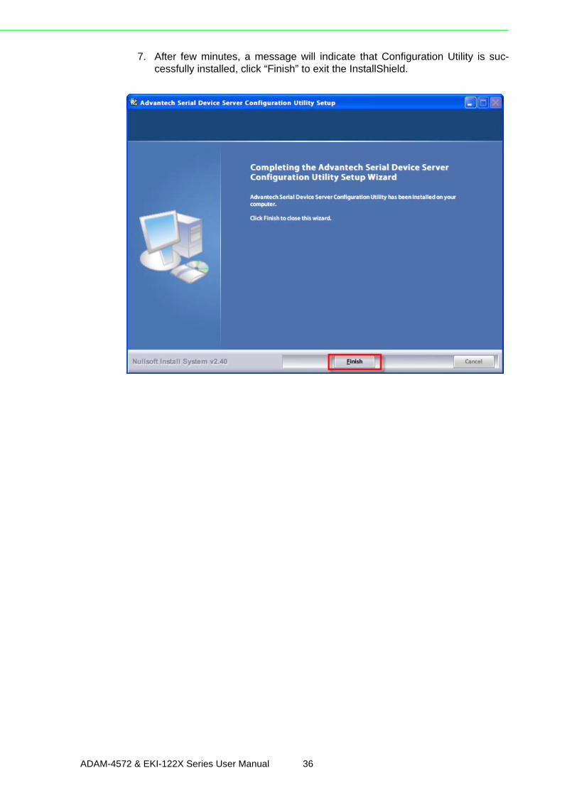
7. After few minutes, a message will indicate that Configuration Utility is suc-cessfully installed, click “Finish” to exit the InstallShield.
ADAM-4572 & EKI-122X Series User Manual 36
Chapter 3
Configuration
3.2 Starting the Configuration UtilityAdvantech provides an easy-to-use configuration utility to configure your ModbusGateways through an Ethernet connection. For secure administration, it can alsorestrict the access rights for configuration to only one host PC to enhance networksecurity. With this secure function enabled, other PCs will not have permission forconfiguration. After the installation program on the Advantech IEDG Series DriverUtility CD-ROM is finished, the serial device servers will be ready for use and config-ure.
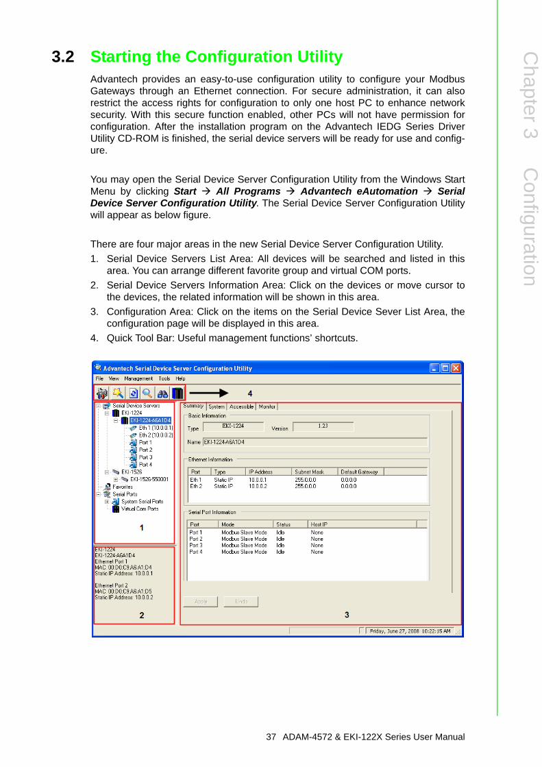
You may open the Serial Device Server Configuration Utility from the Windows StartMenu by clicking Start All Programs Advantech eAutomation SerialDevice Server Configuration Utility. The Serial Device Server Configuration Utilitywill appear as below figure.
There are four major areas in the new Serial Device Server Configuration Utility.1. Serial Device Servers List Area: All devices will be searched and listed in this
area. You can arrange different favorite group and virtual COM ports.2. Serial Device Servers Information Area: Click on the devices or move cursor to
the devices, the related information will be shown in this area.3. Configuration Area: Click on the items on the Serial Device Sever List Area, the
configuration page will be displayed in this area.4. Quick Tool Bar: Useful management functions’ shortcuts.
37 ADAM-4572 & EKI-122X Series User Manual
3.3 Discovering Modbus Gateways
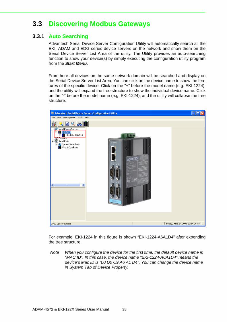
3.3.1 Auto SearchingAdvantech Serial Device Server Configuration Utility will automatically search all theEKI, ADAM and EDG series device servers on the network and show them on theSerial Device Server List Area of the utility. The Utility provides an auto-searchingfunction to show your device(s) by simply executing the configuration utility programfrom the Start Menu.
From here all devices on the same network domain will be searched and display onthe Serial Device Server List Area. You can click on the device name to show the fea-tures of the specific device. Click on the "+" before the model name (e.g. EKI-1224),and the utility will expand the tree structure to show the individual device name. Clickon the “-“ before the model name (e.g. EKI-1224), and the utility will collapse the treestructure.
For example, EKI-1224 in this figure is shown “EKI-1224-A6A1D4” after expendingthe tree structure.
Note When you configure the device for the first time, the default device name is “MAC ID”. In this case, the device name “EKI-1224-A6A1D4” means the device’s Mac ID is “00 D0 C9 A6 A1 D4”. You can change the device name in System Tab of Device Property.
ADAM-4572 & EKI-122X Series User Manual 38
Chapter 3
Configuration
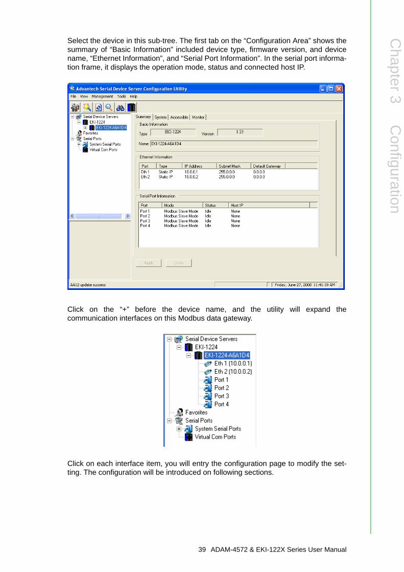
Select the device in this sub-tree. The first tab on the “Configuration Area” shows thesummary of “Basic Information” included device type, firmware version, and devicename, “Ethernet Information”, and “Serial Port Information”. In the serial port informa-tion frame, it displays the operation mode, status and connected host IP.
Click on the “+” before the device name, and the utility will expand thecommunication interfaces on this Modbus data gateway.
Click on each interface item, you will entry the configuration page to modify the set-ting. The configuration will be introduced on following sections.
39 ADAM-4572 & EKI-122X Series User Manual
ADAM-4572 & EKI-122X Series User Manual 40
Chapter 3
Configuration
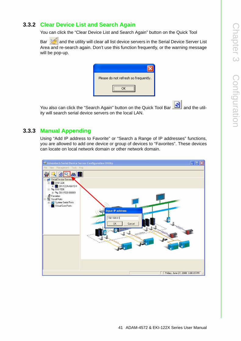
3.3.2 Clear Device List and Search AgainYou can click the “Clear Device List and Search Again” button on the Quick Tool
Bar and the utility will clear all list device servers in the Serial Device Server ListArea and re-search again. Don’t use this function frequently, or the warning messagewill be pop-up.
You also can click the “Search Again” button on the Quick Tool Bar and the util-ity will search serial device servers on the local LAN.
3.3.3 Manual AppendingUsing “Add IP address to Favorite” or “Search a Range of IP addresses” functions,you are allowed to add one device or group of devices to “Favorites”. These devicescan locate on local network domain or other network domain.
41 ADAM-4572 & EKI-122X Series User Manual
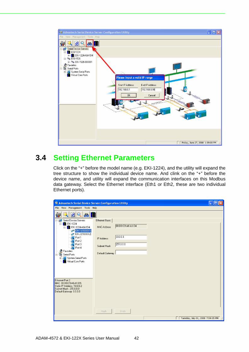
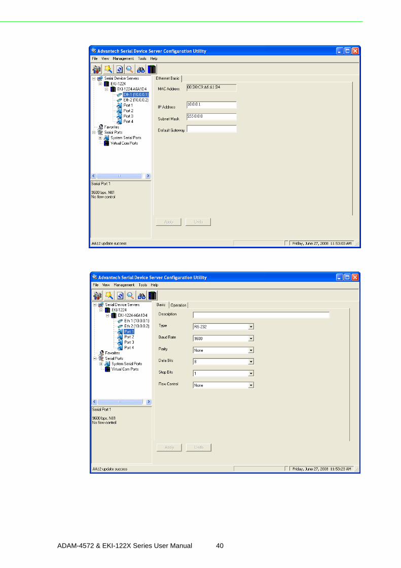
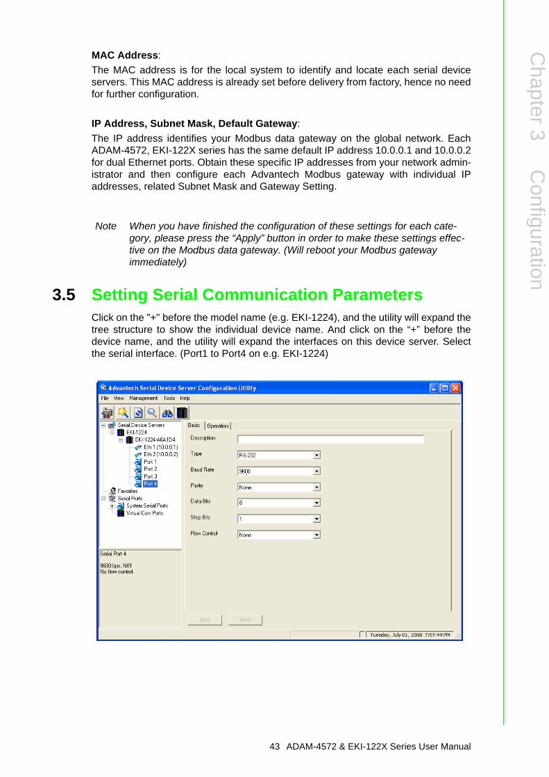
3.4 Setting Ethernet ParametersClick on the “+” before the model name (e.g. EKI-1224), and the utility will expand thetree structure to show the individual device name. And clink on the “+” before thedevice name, and utility will expand the communication interfaces on this Modbusdata gateway. Select the Ethernet interface (Eth1 or Eth2, these are two individualEthernet ports).
ADAM-4572 & EKI-122X Series User Manual 42
Chapter 3
Configuration
MAC Address: The MAC address is for the local system to identify and locate each serial deviceservers. This MAC address is already set before delivery from factory, hence no needfor further configuration.
IP Address, Subnet Mask, Default Gateway:The IP address identifies your Modbus data gateway on the global network. EachADAM-4572, EKI-122X series has the same default IP address 10.0.0.1 and 10.0.0.2for dual Ethernet ports. Obtain these specific IP addresses from your network admin-istrator and then configure each Advantech Modbus gateway with individual IPaddresses, related Subnet Mask and Gateway Setting.
3.5 Setting Serial Communication ParametersClick on the "+" before the model name (e.g. EKI-1224), and the utility will expand thetree structure to show the individual device name. And click on the “+” before thedevice name, and the utility will expand the interfaces on this device server. Selectthe serial interface. (Port1 to Port4 on e.g. EKI-1224)
Note When you have finished the configuration of these settings for each cate-gory, please press the “Apply” button in order to make these settings effec-tive on the Modbus data gateway. (Will reboot your Modbus gateway immediately)
43 ADAM-4572 & EKI-122X Series User Manual
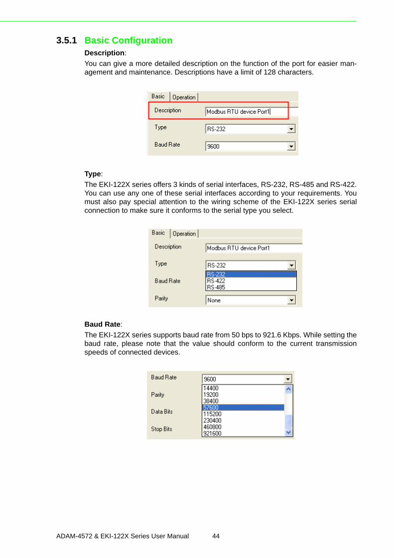
3.5.1 Basic ConfigurationDescription:You can give a more detailed description on the function of the port for easier man-agement and maintenance. Descriptions have a limit of 128 characters.
Type:The EKI-122X series offers 3 kinds of serial interfaces, RS-232, RS-485 and RS-422.You can use any one of these serial interfaces according to your requirements. Youmust also pay special attention to the wiring scheme of the EKI-122X series serialconnection to make sure it conforms to the serial type you select.
Baud Rate:The EKI-122X series supports baud rate from 50 bps to 921.6 Kbps. While setting thebaud rate, please note that the value should conform to the current transmissionspeeds of connected devices.
ADAM-4572 & EKI-122X Series User Manual 44
Chapter 3
Configuration
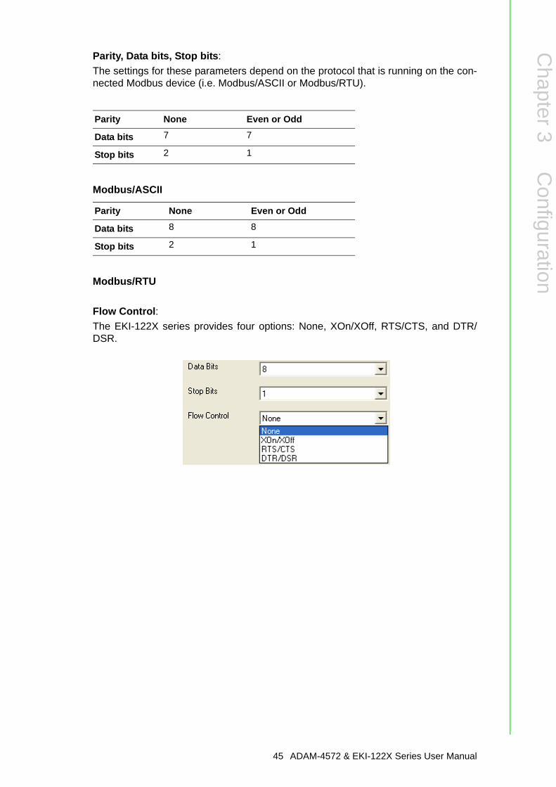
Parity, Data bits, Stop bits:The settings for these parameters depend on the protocol that is running on the con-nected Modbus device (i.e. Modbus/ASCII or Modbus/RTU).
Modbus/ASCII
Modbus/RTU
Flow Control:The EKI-122X series provides four options: None, XOn/XOff, RTS/CTS, and DTR/DSR.
Parity None Even or Odd
Data bits 7 7
Stop bits 2 1
Parity None Even or Odd
Data bits 8 8
Stop bits 2 1
45 ADAM-4572 & EKI-122X Series User Manual
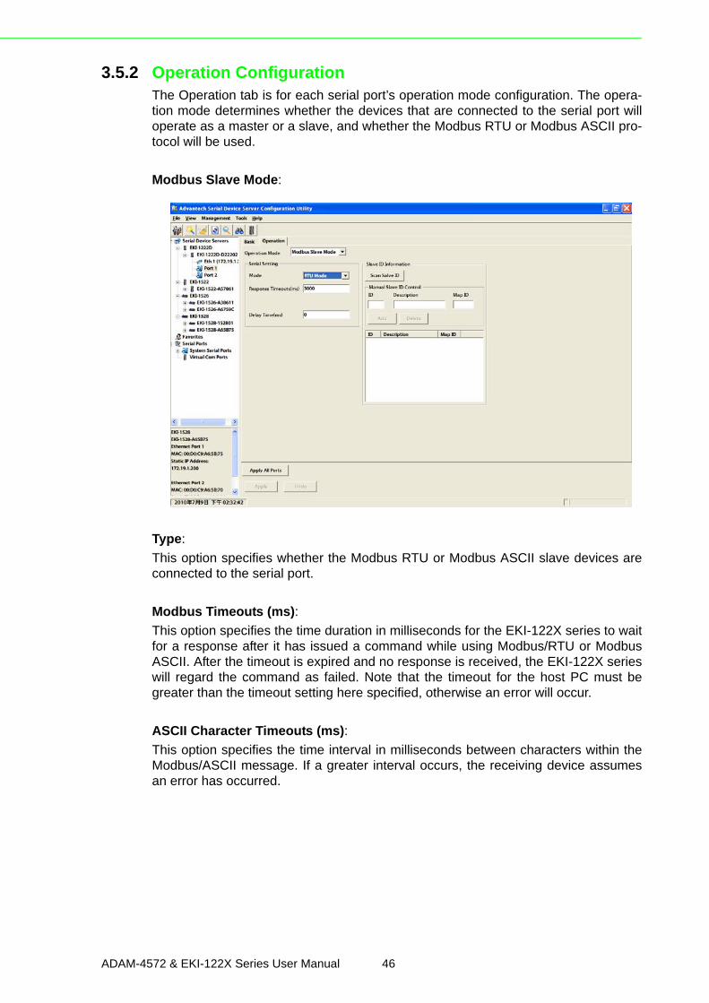
3.5.2 Operation ConfigurationThe Operation tab is for each serial port’s operation mode configuration. The opera-tion mode determines whether the devices that are connected to the serial port willoperate as a master or a slave, and whether the Modbus RTU or Modbus ASCII pro-tocol will be used.
Modbus Slave Mode:
Type:This option specifies whether the Modbus RTU or Modbus ASCII slave devices areconnected to the serial port.
Modbus Timeouts (ms):This option specifies the time duration in milliseconds for the EKI-122X series to waitfor a response after it has issued a command while using Modbus/RTU or ModbusASCII. After the timeout is expired and no response is received, the EKI-122X serieswill regard the command as failed. Note that the timeout for the host PC must begreater than the timeout setting here specified, otherwise an error will occur.
ASCII Character Timeouts (ms):This option specifies the time interval in milliseconds between characters within theModbus/ASCII message. If a greater interval occurs, the receiving device assumesan error has occurred.
ADAM-4572 & EKI-122X Series User Manual 46
Chapter 3
Configuration
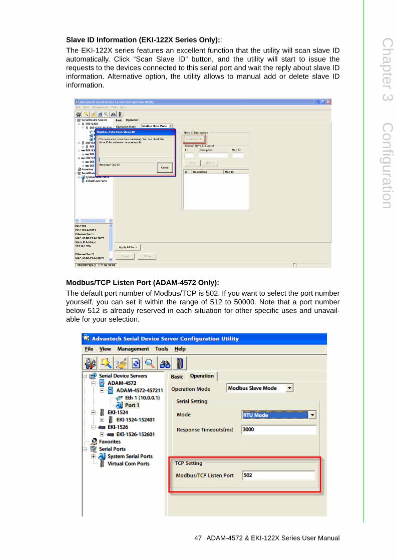
Slave ID Information (EKI-122X Series Only)::The EKI-122X series features an excellent function that the utility will scan slave IDautomatically. Click “Scan Slave ID” button, and the utility will start to issue therequests to the devices connected to this serial port and wait the reply about slave IDinformation. Alternative option, the utility allows to manual add or delete slave IDinformation.
Modbus/TCP Listen Port (ADAM-4572 Only):The default port number of Modbus/TCP is 502. If you want to select the port numberyourself, you can set it within the range of 512 to 50000. Note that a port numberbelow 512 is already reserved in each situation for other specific uses and unavail-able for your selection.
47 ADAM-4572 & EKI-122X Series User Manual
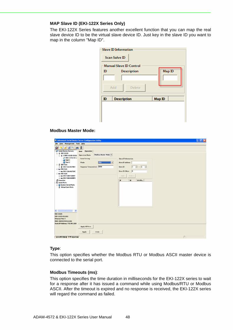
MAP Slave ID (EKI-122X Series Only) The EKI-122X Series features another excellent function that you can map the realslave device ID to be the virtual slave device ID. Just key in the slave ID you want tomap in the column "Map ID".
Modbus Master Mode:
Type:This option specifies whether the Modbus RTU or Modbus ASCII master device isconnected to the serial port.
Modbus Timeouts (ms):This option specifies the time duration in milliseconds for the EKI-122X series to waitfor a response after it has issued a command while using Modbus/RTU or ModbusASCII. After the timeout is expired and no response is received, the EKI-122X serieswill regard the command as failed.
ADAM-4572 & EKI-122X Series User Manual 48
Chapter 3
Configuration
ASCII Character Timeouts (ms):This option specifies the time interval in milliseconds between characters within theModbus/ASCII message. If a greater interval occurs, the receiving device assumesan error has occurred.
Slave IP Information:This option specifies the slave IP address and slave ID of the Modbus TCP slavedevice or another EKI-122X series acts the Modbus slave device. Type the IPaddress in the column and its slave ID range, then click “Add” or “Delete” button toadd or remove the slave IP list.
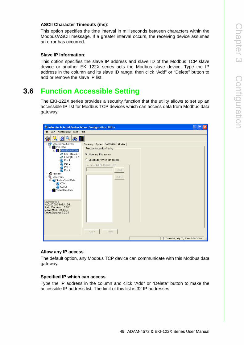
3.6 Function Accessible SettingThe EKI-122X series provides a security function that the utility allows to set up anaccessible IP list for Modbus TCP devices which can access data from Modbus datagateway.
Allow any IP access:The default option, any Modbus TCP device can communicate with this Modbus datagateway.
Specified IP which can access:Type the IP address in the column and click “Add” or “Delete” button to make theaccessible IP address list. The limit of this list is 32 IP addresses.
49 ADAM-4572 & EKI-122X Series User Manual
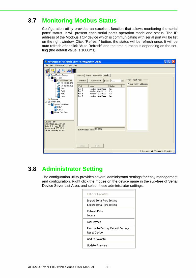
3.7 Monitoring Modbus StatusConfiguration utility provides an excellent function that allows monitoring the serialports’ status. It will present each serial port’s operation mode and status. The IPaddress of the Modbus TCP device which is communicating with serial port will be liston the right window. Click “Refresh” button, the status will be refresh once. It will beauto refresh after click “Auto Refresh” and the time duration is depending on the set-ting (the default value is 1000ms).
3.8 Administrator SettingThe configuration utility provides several administrator settings for easy managementand configuration. Right click the mouse on the device name in the sub-tree of SerialDevice Sever List Area, and select these administrator settings.
ADAM-4572 & EKI-122X Series User Manual 50
Chapter 3
Configuration
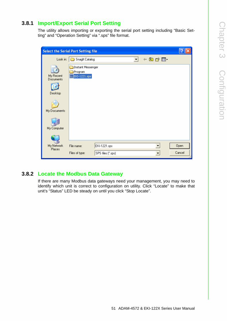
3.8.1 Import/Export Serial Port SettingThe utility allows importing or exporting the serial port setting including “Basic Set-ting” and “Operation Setting” via “.sps” file format.
3.8.2 Locate the Modbus Data GatewayIf there are many Modbus data gateways need your management, you may need toidentify which unit is correct to configuration on utility. Click “Locate” to make thatunit’s “Status” LED be steady on until you click “Stop Locate”.
51 ADAM-4572 & EKI-122X Series User Manual
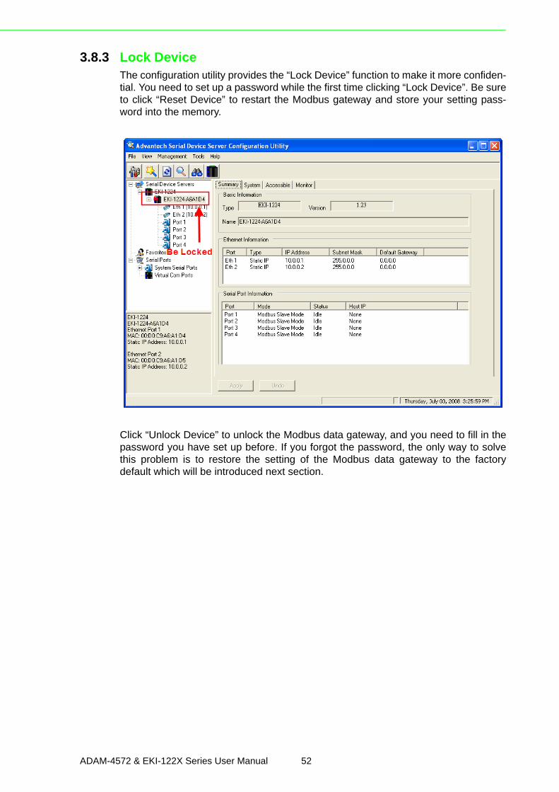
3.8.3 Lock DeviceThe configuration utility provides the “Lock Device” function to make it more confiden-tial. You need to set up a password while the first time clicking “Lock Device”. Be sureto click “Reset Device” to restart the Modbus gateway and store your setting pass-word into the memory.
Click “Unlock Device” to unlock the Modbus data gateway, and you need to fill in thepassword you have set up before. If you forgot the password, the only way to solvethis problem is to restore the setting of the Modbus data gateway to the factorydefault which will be introduced next section.
ADAM-4572 & EKI-122X Series User Manual 52
Chapter 3
Configuration
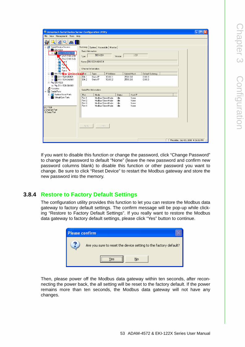
If you want to disable this function or change the password, click “Change Password”to change the password to default “None” (leave the new password and confirm newpassword columns blank) to disable this function or other password you want tochange. Be sure to click “Reset Device” to restart the Modbus gateway and store thenew password into the memory.
3.8.4 Restore to Factory Default SettingsThe configuration utility provides this function to let you can restore the Modbus datagateway to factory default settings. The confirm message will be pop-up while click-ing “Restore to Factory Default Settings”. If you really want to restore the Modbusdata gateway to factory default settings, please click “Yes” button to continue.
Then, please power off the Modbus data gateway within ten seconds, after recon-necting the power back, the all setting will be reset to the factory default. If the powerremains more than ten seconds, the Modbus data gateway will not have anychanges.
53 ADAM-4572 & EKI-122X Series User Manual
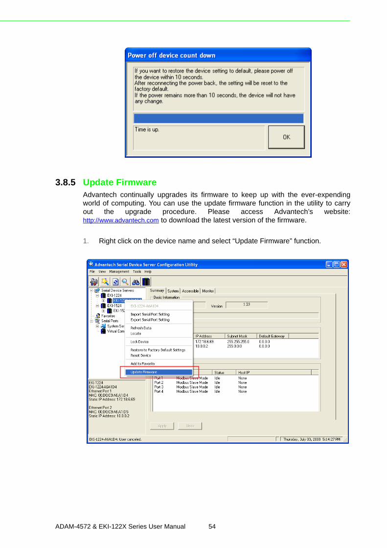
3.8.5 Update FirmwareAdvantech continually upgrades its firmware to keep up with the ever-expendingworld of computing. You can use the update firmware function in the utility to carryout the upgrade procedure. Please access Advantech’s website:http://www.advantech.com to download the latest version of the firmware.
1. Right click on the device name and select “Update Firmware” function.
ADAM-4572 & EKI-122X Series User Manual 54
Chapter 3
Configuration
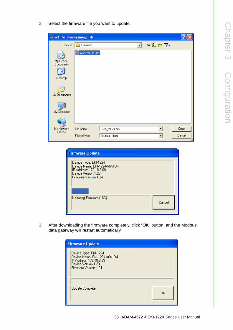
2. Select the firmware file you want to update.
3. After downloading the firmware completely, click “OK” button, and the Modbus data gateway will restart automatically.
55 ADAM-4572 & EKI-122X Series User Manual

www.advantech.comPlease verify specifications before quoting. This guide is intended for referencepurposes only.All product specifications are subject to change without notice.No part of this publication may be reproduced in any form or by any means,electronic, photocopying, recording or otherwise, without prior written permis-sion of the publisher.All brand and product names are trademarks or registered trademarks of theirrespective companies.© Advantech Co., Ltd. 2010