Embed Size (px)
Citation preview
NOTICE By purchasing any item sold by Rough Country, LLC, the buyer expressly warrants that he/she is in compliance with all applicable Federal, State, and Local laws and regulations regarding the purchase, ownership, and use of the item. It shall be the buyers responsibility to comply with all Federal, State and Local laws governing the sales of any items listed, illustrated or sold. The buyer expressly agrees to indemnify and hold harmless Rough Country, LLC for all claims resulting directly or indirectly from the purchase, ownership, or use of the items.
Thank you for choosing Rough Country for your suspension needs.
Rough Country recommends a certified technician install this system. In addition to these instructions, professional knowl-edge of disassemble/reassembly procedures as well as post installation checks must be known. Attempts to install this sys-tem without this knowledge and expertise may jeopardize the integrity and/or operating safety of the vehicle.
Please read instructions before beginning installation. Check the kit hardware against the parts list on the rear cover of these instructions. Be sure you have all needed parts and know where they go. Also please review tools needed list and make sure you have needed tools.
PRODUCT USE INFORMATION
As a general rule, the taller a vehicle is, the easier it will roll. Seat belts and shoulder harnesses should be worn at all times. Avoid situations where a side rollover may occur. Generally, braking performance and capability are de-creased when larger/heavier tires and wheels are used. Take this into consideration while driving. Do not add, alter, or fabri-cate any factory or after-market parts to increase vehicle height over the intended height of the Rough Country product pur-chased. Mixing component brands is not recommended.
Rough Country makes no claims regarding lifting devices and excludes any and all implied claims. We will not be responsi-ble for any product that is altered. If question exist we will be happy to answer any questions concerning the design, func-tion, and correct use of our products. The electric power steering must be unplugged before any of the steering components are removed. Failure to do so may cause damage to the electric power steering. Trucks equipped with a mass damper on the front diff, the damper will have to be removed.
This kit is packaged as a leveling kit—raising the front 5” and the back 3.25”. If you desire a different look or if the vehicle has a tool box or added weight in the rear, please consult with your sales representative about other block and u-bolt op-tions.
This suspension system was developed using a 33” x 12.5” tire with 20” x 9” wheel and a offset of –12mm to +18mm. If wider tires are used, offset wheels will be required and trimming may be required. DEALER AND VEHICLE OWNER
Any vehicle equipped with any Rough Country product should have a “Warning to Driver” decal installed on the inside of the windshield or on the vehicle’s dash. The decal should act as a constant reminder for whoever is operating the vehicle.
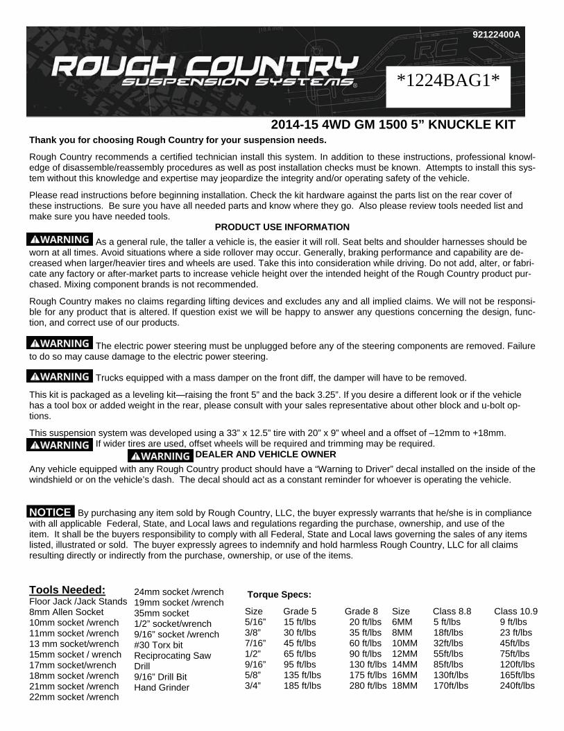
2014-15 4WD GM 1500 5” KNUCKLE KIT
Tools Needed: Floor Jack /Jack Stands 8mm Allen Socket 10mm socket /wrench 11mm socket /wrench 13 mm socket/wrench 15mm socket / wrench 17mm socket/wrench 18mm socket /wrench 21mm socket /wrench 22mm socket /wrench
24mm socket /wrench 19mm socket /wrench 35mm socket 1/2” socket/wrench 9/16” socket /wrench #30 Torx bit Reciprocating Saw Drill 9/16” Drill Bit Hand Grinder
Size Class 8.8 Class 10.9 6MM 5 ft/lbs 9 ft/lbs 8MM 18ft/lbs 23 ft/lbs 10MM 32ft/lbs 45ft/lbs 12MM 55ft/lbs 75ft/lbs 14MM 85ft/lbs 120ft/lbs 16MM 130ft/lbs 165ft/lbs 18MM 170ft/lbs 240ft/lbs
Torque Specs:
Size Grade 5 Grade 8 5/16” 15 ft/lbs 20 ft/lbs 3/8” 30 ft/lbs 35 ft/lbs 7/16” 45 ft/lbs 60 ft/lbs 1/2” 65 ft/lbs 90 ft/lbs 9/16” 95 ft/lbs 130 ft/lbs 5/8” 135 ft/lbs 175 ft/lbs 3/4” 185 ft/lbs 280 ft/lbs
92122400A
*1224BAG1*
Thank you for choosing Rough Country for your suspension needs.
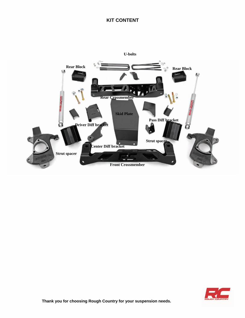
KIT CONTENT
Rear Block
Strut spacer
U-bolts
Pass Diff bracket Driver Diff bracket
Rear Crossmember
Front Crossmember
Strut spacer
Rear Block
Skid Plate
Center Diff bracket
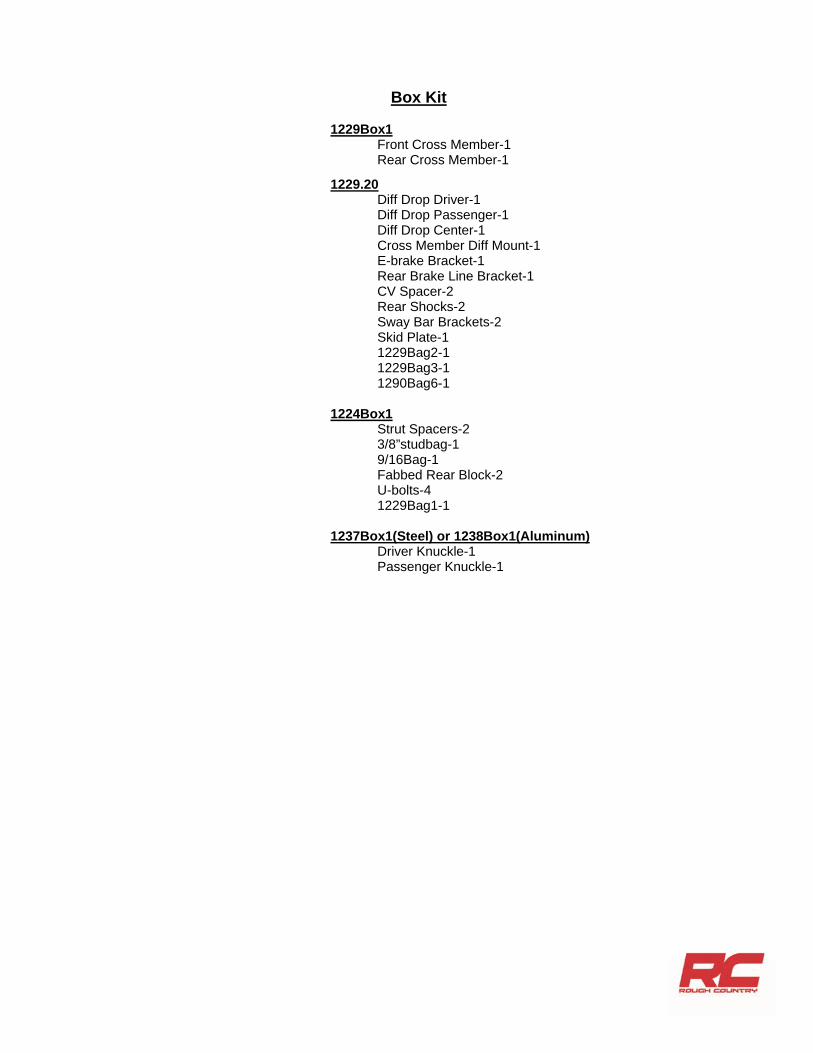
Box Kit
1229Box1 Front Cross Member-1 Rear Cross Member-1
1229.20 Diff Drop Driver-1 Diff Drop Passenger-1 Diff Drop Center-1 Cross Member Diff Mount-1 E-brake Bracket-1 Rear Brake Line Bracket-1 CV Spacer-2 Rear Shocks-2 Sway Bar Brackets-2 Skid Plate-1 1229Bag2-1 1229Bag3-1 1290Bag6-1 1224Box1 Strut Spacers-2 3/8”studbag-1 9/16Bag-1 Fabbed Rear Block-2 U-bolts-4 1229Bag1-1 1237Box1(Steel) or 1238Box1(Aluminum) Driver Knuckle-1 Passenger Knuckle-1
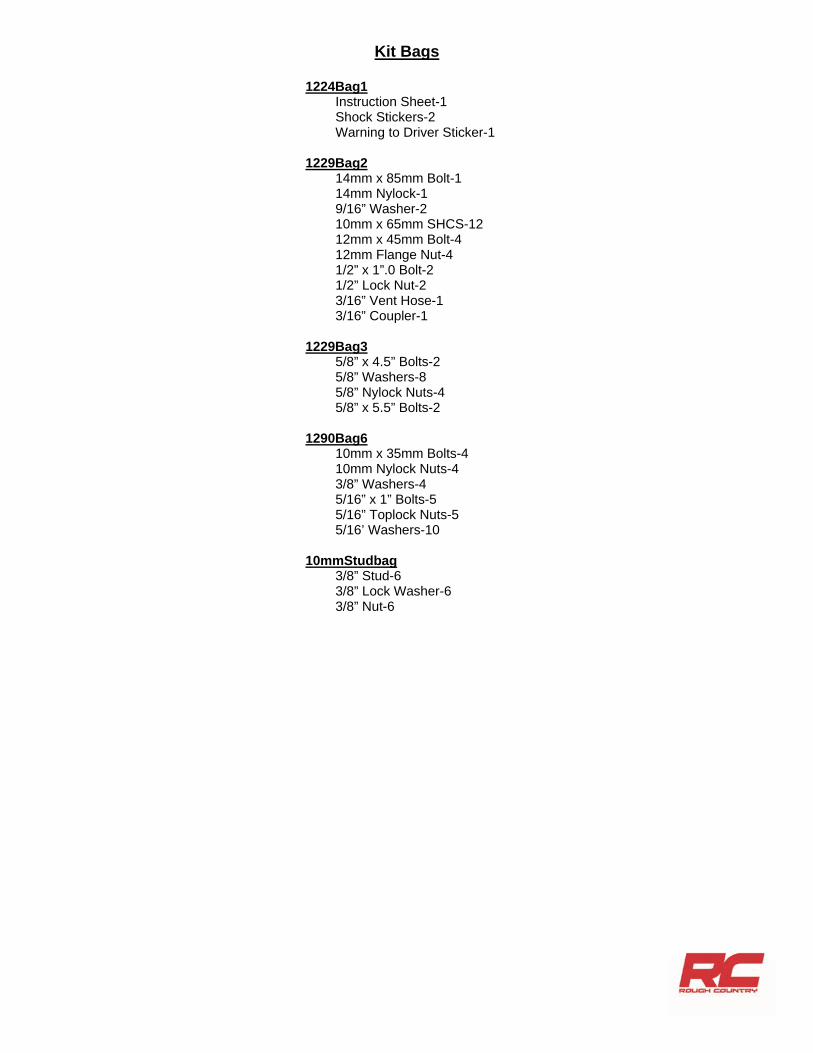
Kit Bags
1224Bag1 Instruction Sheet-1 Shock Stickers-2 Warning to Driver Sticker-1 1229Bag2 14mm x 85mm Bolt-1 14mm Nylock-1 9/16” Washer-2 10mm x 65mm SHCS-12 12mm x 45mm Bolt-4 12mm Flange Nut-4 1/2” x 1”.0 Bolt-2 1/2” Lock Nut-2 3/16” Vent Hose-1 3/16” Coupler-1 1229Bag3 5/8” x 4.5” Bolts-2 5/8” Washers-8 5/8” Nylock Nuts-4 5/8” x 5.5” Bolts-2 1290Bag6 10mm x 35mm Bolts-4 10mm Nylock Nuts-4 3/8” Washers-4 5/16” x 1” Bolts-5 5/16” Toplock Nuts-5 5/16’ Washers-10 10mmStudbag 3/8” Stud-6 3/8” Lock Washer-6 3/8” Nut-6
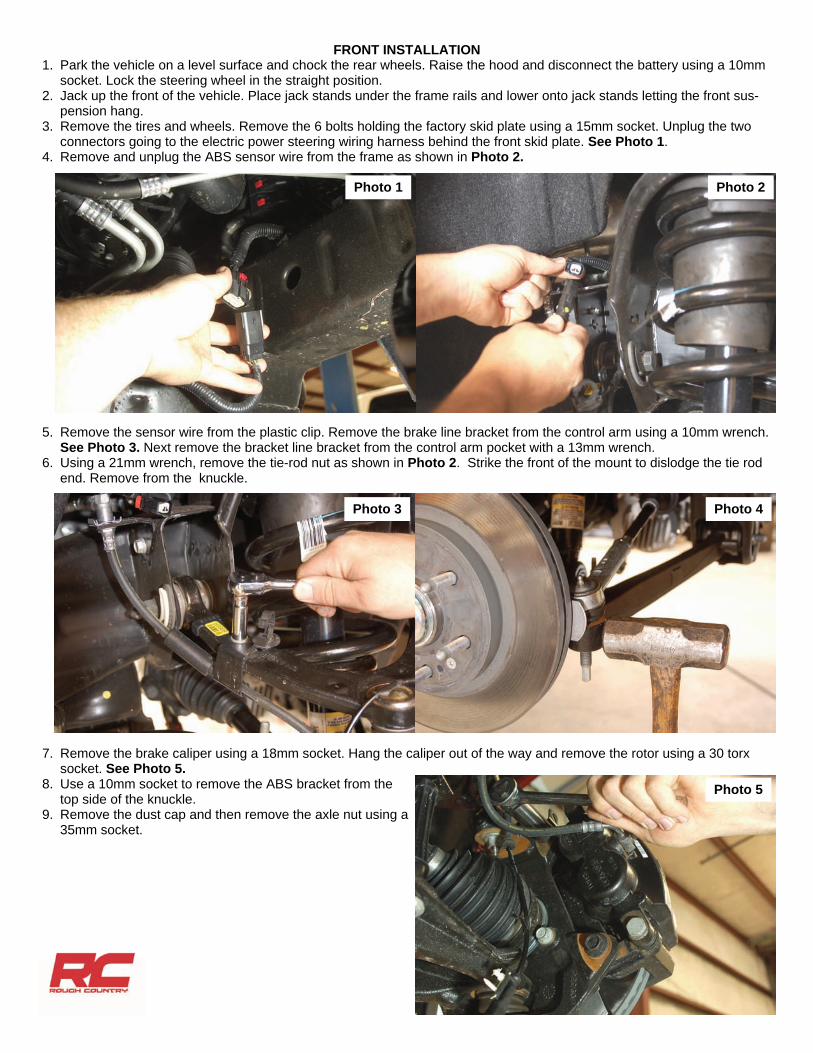
FRONT INSTALLATION 1. Park the vehicle on a level surface and chock the rear wheels. Raise the hood and disconnect the battery using a 10mm
socket. Lock the steering wheel in the straight position. 2. Jack up the front of the vehicle. Place jack stands under the frame rails and lower onto jack stands letting the front sus-
pension hang. 3. Remove the tires and wheels. Remove the 6 bolts holding the factory skid plate using a 15mm socket. Unplug the two
connectors going to the electric power steering wiring harness behind the front skid plate. See Photo 1. 4. Remove and unplug the ABS sensor wire from the frame as shown in Photo 2.
5. Remove the sensor wire from the plastic clip. Remove the brake line bracket from the control arm using a 10mm wrench. See Photo 3. Next remove the bracket line bracket from the control arm pocket with a 13mm wrench.
6. Using a 21mm wrench, remove the tie-rod nut as shown in Photo 2. Strike the front of the mount to dislodge the tie rod end. Remove from the knuckle.
7. Remove the brake caliper using a 18mm socket. Hang the caliper out of the way and remove the rotor using a 30 torx socket. See Photo 5.
8. Use a 10mm socket to remove the ABS bracket from the top side of the knuckle.
9. Remove the dust cap and then remove the axle nut using a 35mm socket.
Photo 5
Photo 2 Photo 1
Photo 3 Photo 4
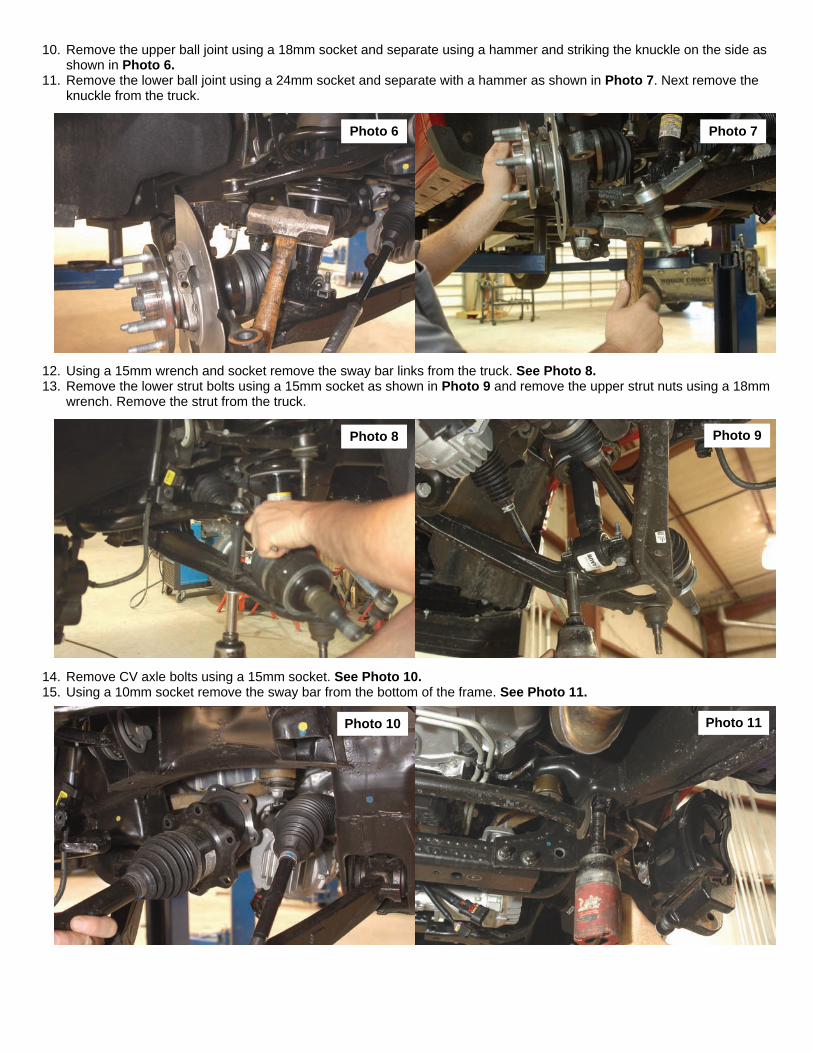
10. Remove the upper ball joint using a 18mm socket and separate using a hammer and striking the knuckle on the side as shown in Photo 6.
11. Remove the lower ball joint using a 24mm socket and separate with a hammer as shown in Photo 7. Next remove the knuckle from the truck.
12. Using a 15mm wrench and socket remove the sway bar links from the truck. See Photo 8. 13. Remove the lower strut bolts using a 15mm socket as shown in Photo 9 and remove the upper strut nuts using a 18mm
wrench. Remove the strut from the truck.
14. Remove CV axle bolts using a 15mm socket. See Photo 10. 15. Using a 10mm socket remove the sway bar from the bottom of the frame. See Photo 11.
Photo 6 Photo 7
Photo 8 Photo 9
Photo 10 Photo 11
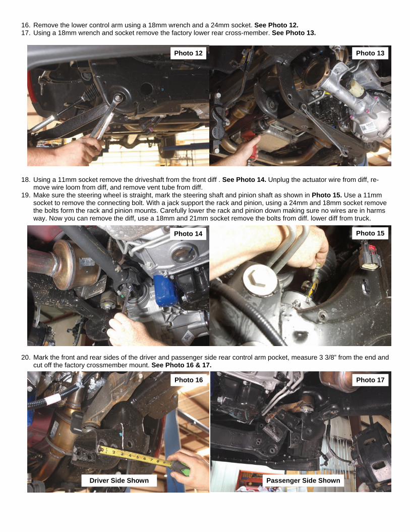
16. Remove the lower control arm using a 18mm wrench and a 24mm socket. See Photo 12. 17. Using a 18mm wrench and socket remove the factory lower rear cross-member. See Photo 13.
18. Using a 11mm socket remove the driveshaft from the front diff . See Photo 14. Unplug the actuator wire from diff, re-move wire loom from diff, and remove vent tube from diff.
19. Make sure the steering wheel is straight, mark the steering shaft and pinion shaft as shown in Photo 15. Use a 11mm socket to remove the connecting bolt. With a jack support the rack and pinion, using a 24mm and 18mm socket remove the bolts form the rack and pinion mounts. Carefully lower the rack and pinion down making sure no wires are in harms way. Now you can remove the diff, use a 18mm and 21mm socket remove the bolts from diff. lower diff from truck.
20. Mark the front and rear sides of the driver and passenger side rear control arm pocket, measure 3 3/8” from the end and cut off the factory crossmember mount. See Photo 16 & 17.
Photo 12 Photo 13
Photo 14 Photo 15
Photo 16 Photo 17
Driver Side Shown Passenger Side Shown
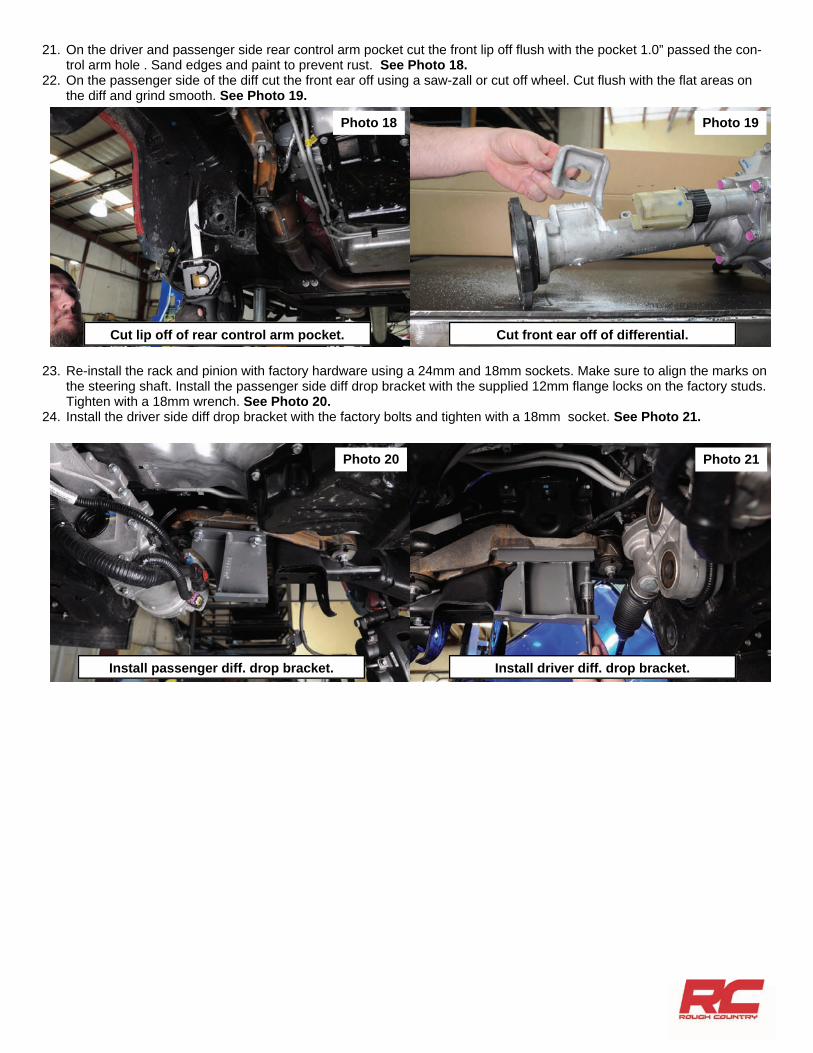
21. On the driver and passenger side rear control arm pocket cut the front lip off flush with the pocket 1.0” passed the con-trol arm hole . Sand edges and paint to prevent rust. See Photo 18.
22. On the passenger side of the diff cut the front ear off using a saw-zall or cut off wheel. Cut flush with the flat areas on the diff and grind smooth. See Photo 19.
23. Re-install the rack and pinion with factory hardware using a 24mm and 18mm sockets. Make sure to align the marks on the steering shaft. Install the passenger side diff drop bracket with the supplied 12mm flange locks on the factory studs. Tighten with a 18mm wrench. See Photo 20.
24. Install the driver side diff drop bracket with the factory bolts and tighten with a 18mm socket. See Photo 21.
Photo 18 Photo 19
Photo 20 Photo 21
Cut lip off of rear control arm pocket. Cut front ear off of differential.
Install passenger diff. drop bracket. Install driver diff. drop bracket.
25. Install the diff using the supplied 12mm bolts and flange nuts on the driver side and 12mm bolts with stock nuts on the passenger side. Do not tighten at this time.
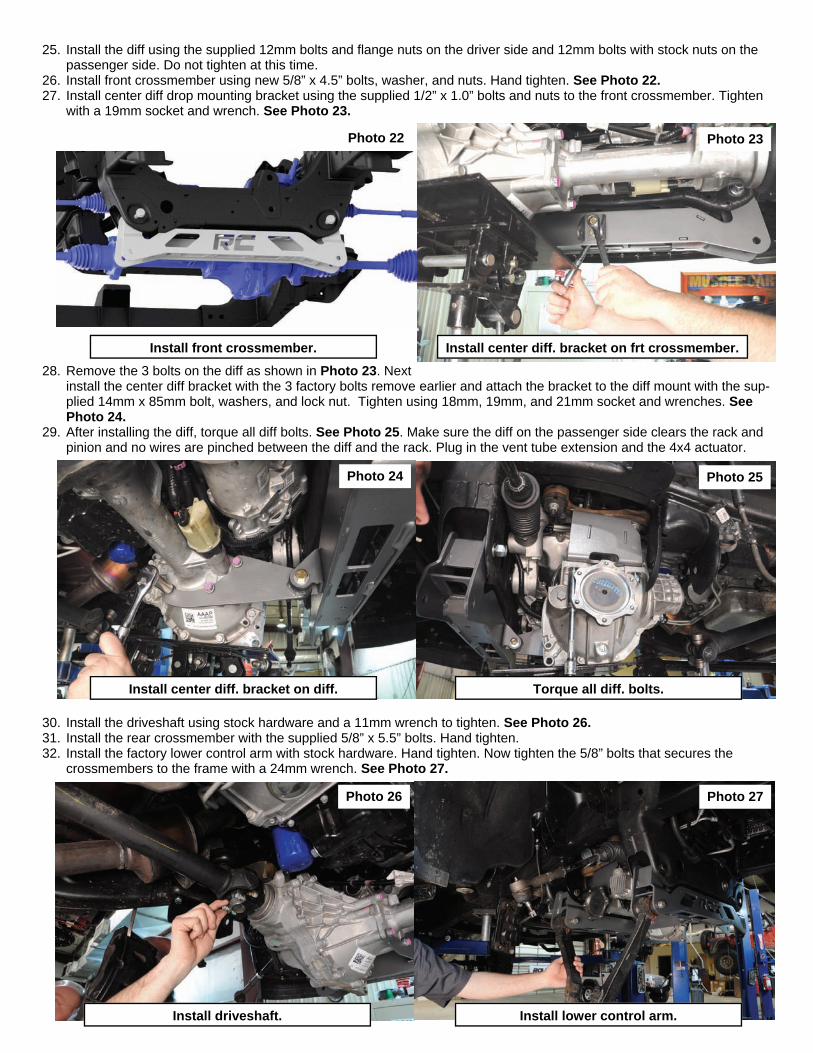
26. Install front crossmember using new 5/8” x 4.5” bolts, washer, and nuts. Hand tighten. See Photo 22. 27. Install center diff drop mounting bracket using the supplied 1/2” x 1.0” bolts and nuts to the front crossmember. Tighten
with a 19mm socket and wrench. See Photo 23.
28. Remove the 3 bolts on the diff as shown in Photo 23. Next install the center diff bracket with the 3 factory bolts remove earlier and attach the bracket to the diff mount with the sup-plied 14mm x 85mm bolt, washers, and lock nut. Tighten using 18mm, 19mm, and 21mm socket and wrenches. See Photo 24.
29. After installing the diff, torque all diff bolts. See Photo 25. Make sure the diff on the passenger side clears the rack and pinion and no wires are pinched between the diff and the rack. Plug in the vent tube extension and the 4x4 actuator.
30. Install the driveshaft using stock hardware and a 11mm wrench to tighten. See Photo 26. 31. Install the rear crossmember with the supplied 5/8” x 5.5” bolts. Hand tighten. 32. Install the factory lower control arm with stock hardware. Hand tighten. Now tighten the 5/8” bolts that secures the
crossmembers to the frame with a 24mm wrench. See Photo 27.
Photo 23
Photo 25 Photo 24
Photo 22
Photo 26 Photo 27
Install front crossmember. Install center diff. bracket on frt crossmember.
Install center diff. bracket on diff. Torque all diff. bolts.
Install driveshaft. Install lower control arm.
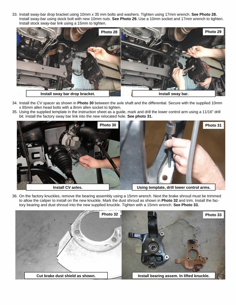
33. Install sway-bar drop bracket using 10mm x 35 mm bolts and washers. Tighten using 17mm wrench. See Photo 28. Install sway-bar using stock bolt with new 10mm nuts. See Photo 29. Use a 10mm socket and 17mm wrench to tighten. Install stock sway-bar link using a 15mm to tighten.
34. Install the CV spacer as shown in Photo 30 between the axle shaft and the differential. Secure with the supplied 10mm x 65mm allen head bolts with a 8mm allen socket to tighten.
35. Using the supplied template in the instruction sheet as a guide, mark and drill the lower control arm using a 11/16” drill bit. Install the factory sway bar link into the new relocated hole. See photo 31.
36. On the factory knuckles, remove the bearing assembly using a 15mm wrench. Next the brake shroud must be trimmed to allow the caliper to install on the new knuckle. Mark the dust shroud as shown in Photo 32 and trim. Install the fac-tory bearing and dust shroud into the new supplied knuckle. Tighten with a 15mm wrench. See Photo 33.
Photo 28 Photo 29
Photo 30
Photo 32
Photo 31
Photo 33
Install sway bar drop bracket. Install sway bar.
Install CV axles. Using template, drill lower control arms.
Cut brake dust shield as shown. Install bearing assem. In lifted knuckle.
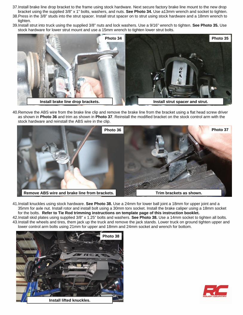
37.Install brake line drop bracket to the frame using stock hardware. Next secure factory brake line mount to the new drop bracket using the supplied 3/8” x 1” bolts, washers, and nuts. See Photo 34. Use a13mm wrench and socket to tighten.
38.Press in the 3/8” studs into the strut spacer. Install strut spacer on to strut using stock hardware and a 18mm wrench to tighten.
39.Install strut into truck using the supplied 3/8” nuts and lock washers. Use a 9/16” wrench to tighten. See Photo 35. Use stock hardware for lower strut mount and use a 15mm wrench to tighten lower strut bolts.
40.Remove the ABS wire from the brake line clip and remove the brake line from the bracket using a flat head screw driver as shown in Photo 36 and trim as shown in Photo 37. Reinstall the modified bracket on the stock control arm with the stock hardware and reinstall the ABS wire in the clip.
41.Install knuckles using stock hardware. See Photo 38. Use a 24mm for lower ball joint a 18mm for upper joint and a 35mm for axle nut. Install rotor and install bolt using a 30mm torx socket. Install the brake caliper using a 18mm socket for the bolts. Refer to Tie Rod trimming instructions on template page of this instruction booklet.
42.Install skid plates using supplied 3/8” x 1.25” bolts and washers. See Photo 38. Use a 14mm socket to tighten all bolts. 43.Install the wheels and tires, them jack up the truck and remove the jack stands. Lower truck on ground tighten upper and
lower control arm bolts using 21mm for upper and 18mm and 24mm socket and wrench for bottom.
Photo 35 Photo 34
Install brake line drop brackets. Install strut spacer and strut.
Photo 36 Photo 37
Remove ABS wire and brake line from brackets. Trim brackets as shown.
Photo 38
Install lifted knuckles.
REAR INSTALLATION
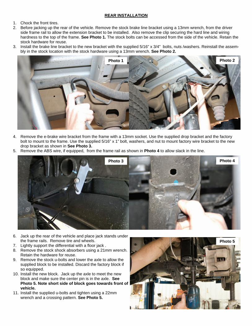
1. Chock the front tires. 2. Before jacking up the rear of the vehicle. Remove the stock brake line bracket using a 13mm wrench, from the driver
side frame rail to allow the extension bracket to be installed. Also remove the clip securing the hard line and wiring hardness to the top of the frame. See Photo 1. The stock bolts can be accessed from the side of the vehicle. Retain the stock hardware for reuse.
3. Install the brake line bracket to the new bracket with the supplied 5/16” x 3/4” bolts, nuts /washers. Reinstall the assem-bly in the stock location with the stock hardware using a 13mm wrench. See Photo 2.
4. Remove the e-brake wire bracket from the frame with a 13mm socket. Use the supplied drop bracket and the factory bolt to mount to the frame. Use the supplied 5/16” x 1” bolt, washers, and nut to mount factory wire bracket to the new drop bracket as shown in See Photo 3.
5. Remove the ABS wire, if equipped, from the frame rail as shown in Photo 4 to allow slack in the line.
6. Jack up the rear of the vehicle and place jack stands under the frame rails. Remove tire and wheels.
7. Lightly support the differential with a floor jack . 8. Remove the stock shock absorbers using a 21mm wrench.
Retain the hardware for reuse. 9. Remove the stock u-bolts and lower the axle to allow the
supplied block to be installed. Discard the factory block if so equipped.
10. Install the new block. Jack up the axle to meet the new block and make sure the center pin is in the axle. See Photo 5. Note short side of block goes towards front of vehicle.
11. Install the supplied u-bolts and tighten using a 22mm wrench and a crossing pattern. See Photo 5.
Photo 1 Photo 2
Photo 3 Photo 4
Photo 5
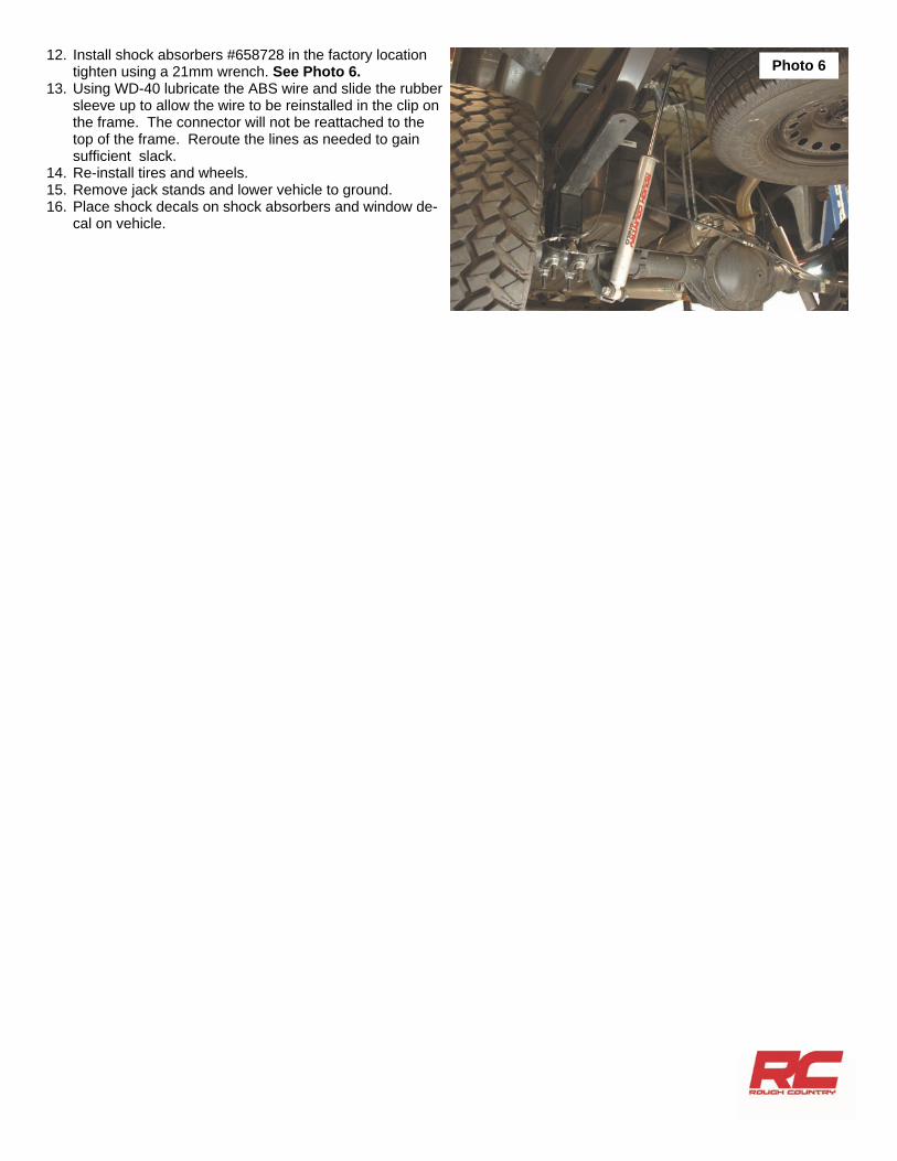
12. Install shock absorbers #658728 in the factory location tighten using a 21mm wrench. See Photo 6.
13. Using WD-40 lubricate the ABS wire and slide the rubber sleeve up to allow the wire to be reinstalled in the clip on the frame. The connector will not be reattached to the top of the frame. Reroute the lines as needed to gain sufficient slack.
14. Re-install tires and wheels. 15. Remove jack stands and lower vehicle to ground. 16. Place shock decals on shock absorbers and window de-
cal on vehicle.
Photo 6
POST INSTALLATION INSTRUCTIONS
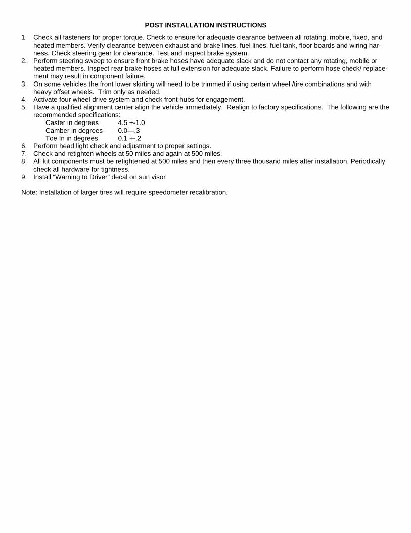
1. Check all fasteners for proper torque. Check to ensure for adequate clearance between all rotating, mobile, fixed, and heated members. Verify clearance between exhaust and brake lines, fuel lines, fuel tank, floor boards and wiring har-ness. Check steering gear for clearance. Test and inspect brake system.
2. Perform steering sweep to ensure front brake hoses have adequate slack and do not contact any rotating, mobile or heated members. Inspect rear brake hoses at full extension for adequate slack. Failure to perform hose check/ replace-ment may result in component failure.
3. On some vehicles the front lower skirting will need to be trimmed if using certain wheel /tire combinations and with heavy offset wheels. Trim only as needed.
4. Activate four wheel drive system and check front hubs for engagement. 5. Have a qualified alignment center align the vehicle immediately. Realign to factory specifications. The following are the
recommended specifications: Caster in degrees 4.5 +-1.0 Camber in degrees 0.0—.3 Toe In in degrees 0.1 +-.2 6. Perform head light check and adjustment to proper settings. 7. Check and retighten wheels at 50 miles and again at 500 miles. 8. All kit components must be retightened at 500 miles and then every three thousand miles after installation. Periodically
check all hardware for tightness. 9. Install “Warning to Driver” decal on sun visor Note: Installation of larger tires will require speedometer recalibration.
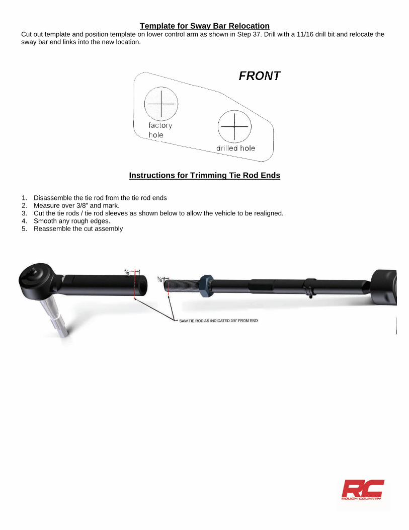
Template for Sway Bar Relocation Cut out template and position template on lower control arm as shown in Step 37. Drill with a 11/16 drill bit and relocate the sway bar end links into the new location.
1. Disassemble the tie rod from the tie rod ends 2. Measure over 3/8” and mark. 3. Cut the tie rods / tie rod sleeves as shown below to allow the vehicle to be realigned. 4. Smooth any rough edges. 5. Reassemble the cut assembly
Instructions for Trimming Tie Rod Ends
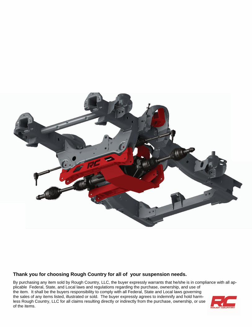
Thank you for choosing Rough Country for all of your suspension needs. By purchasing any item sold by Rough Country, LLC, the buyer expressly warrants that he/she is in compliance with all ap-plicable Federal, State, and Local laws and regulations regarding the purchase, ownership, and use of the item. It shall be the buyers responsibility to comply with all Federal, State and Local laws governing the sales of any items listed, illustrated or sold. The buyer expressly agrees to indemnify and hold harm-less Rough Country, LLC for all claims resulting directly or indirectly from the purchase, ownership, or use of the items.

![SPair-71k: A Large-scale Benchmark for Semantic ...arXiv:1908.10543v1 [cs.CV] 28 Aug 2019 Type View-point diff. Scale diff. Truncation diff. Occlusion diff. easy medi hard easy medi](https://img.pdfslide.us/doc/110x75/6049bbd3adaaa52b560671c6/spair-71k-a-large-scale-benchmark-for-semantic-arxiv190810543v1-cscv-28.jpg)